JP3762123B2 - Multi-projection type screen - Google Patents
Multi-projection type screenDownload PDFInfo
- Publication number
- JP3762123B2 JP3762123B2JP36206598AJP36206598AJP3762123B2JP 3762123 B2JP3762123 B2JP 3762123B2JP 36206598 AJP36206598 AJP 36206598AJP 36206598 AJP36206598 AJP 36206598AJP 3762123 B2JP3762123 B2JP 3762123B2
- Authority
- JP
- Japan
- Prior art keywords
- screen
- lens structure
- joint
- convex lens
- light
- Prior art date
- Legal status (The legal status is an assumption and is not a legal conclusion. Google has not performed a legal analysis and makes no representation as to the accuracy of the status listed.)
- Expired - Fee Related
Links
Images


Landscapes
- Overhead Projectors And Projection Screens (AREA)
- Transforming Electric Information Into Light Information (AREA)
- Devices For Indicating Variable Information By Combining Individual Elements (AREA)
Description
Translated fromJapanese【0001】
【発明の属する技術分野】
この発明は、複数の画面を並べることにより大画面を表示するマルチ投射型スクリーンに関するものである。
【0002】
【従来の技術】
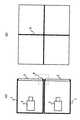
大画面のディスプレイを構成する手段としてマルチ画面がある。これは例えば図1の投射型ディスプレイを図2のように複数個上下左右に重ねることにより、全体として大きな画面を持つディスプレイを構成するものである。投射型ディスプレイは、ディスプレイの筐体1の中に投射装置3を含み、前面がスクリーン2になっている。図2は図1の投射型ディスプレイを4台上下左右各2段重ねて2×2のマルチ画面を構成した例である。
【0003】
【発明が解決しようとする課題】
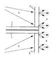
このようにマルチ画面により大型の画面を容易に構成できるが、問題点として画面中に図2(b)に示すような線4が見えてしまうことが挙げられる。これは、重ねた目地4のところで筐体1の厚さの分だけ、そこの部分からは光が出ないからである。図2(a)の目地の部分4を破線の範囲で拡大したものを図3に示す。投射装置3からの入射光5はスクリーン2を通り出射光6として出て行くが、筐体1は通常金属でできており光を通さないため、この部分からは光が出ず画面上では目地の部分が黒い線として見える。この黒い線の幅は数mm程度であるが、マルチ画面を見慣れない人にとっては画質を劣化させる要因となっている。
【0004】
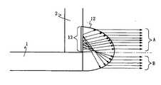
これを解決する方法として図4のように目地の部分に外に凸になっている透明部材である凸レンズ構造12を設ける方法がある(特開平5−173252号「マルチプロジェクタ」より)。この方法によると、図4に示す通り正面から見ると目地の部分からも多少光が出るので、目地の見え方が緩和される。
【0005】
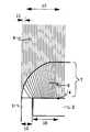
ただし凸レンズ構造については制限が生じる。これを図5で説明する。図5で光の出る方向A,Bともに「凸レンズ構造に光が入る領域」13からの光がいかなければいけないため(そうでなければ暗くなり目地がはっきり目立つ)、凸レンズ構造12は上下非対称でさらにある程度高くなければいけない(高さはディスプレイの筐体1の厚さの2倍程度)。このような高い突起形状では傷がつきやすい。
【0006】
また、領域13からの光で図5のA,B両方の光出力をまかなっているため、このままではこの部分は画面中央部よりもかなり暗くなってしまう。これを防ぐためにこの領域13の部分だけを明るくすることが考えられるが、現在のプロジェクタは画面を明るくするために既に多くの努力をしてしまっているので、この部分での輝度の改善はせいぜい1.3倍位である。そこで領域13を大きくすればいいが、図5で凸レンズ構造12の下側をそのままにして上側だけ変えてもBから出る光は変化がないので、高さも大きくする必要がある。これではさらに傷つきやすい構造になる。
以上示したように、凸レンズ構造では目地の見え方の改善効果は少ないか、または傷つきやすい構造となる。
【0007】
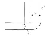
また、これとは別に、図6のように透明なスクリーン取り付け枠15を設けることも考案されている(実開平4−16444号「マルチ映像装置のスクリーン構造」)。この方法ではスクリーン取り付け枠15が湾曲していて結果的にレンズ作用をするので目地が多少目立たなくなる。ただし、十分なレンズ作用をさせて目地の見え方を改善するためには図6のように厚さDよりも厚さCを小さくする必要があるが、これでは取り付け枠としての働きが無くなる(取り付け枠15自体が薄くなるので、取り付け枠としての強度が不足する。)。従って、取り付け枠として機能しながらでは目地の見え方の改善効果は少ない。
【0008】
そこで本発明の目的は、前述のように目立ってしまうマルチ画面の目地を目立たなくしたマルチ投射型スクリーンを提供せんとするものである。
【0009】
【課題を解決するための手段】
この目的を達成するため、本発明マルチ投射型スクリーンは、画像が投射されるスクリーンが前面に装着されるスクリーンブロックを多段に積み上げて大型の画面を形成するマルチ投射型スクリーンにおいて、前記スクリーンブロックが、画像が投射される平行平板スクリーンと、中央が、前記平行平板スクリーンの中央部分を覆う平板レンズ構造を成し、周辺が、前記平行平板スクリーン間の目地部分及び平行平板スクリーンの周辺部分を覆う凸レンズ構造を成し、前記平行平板スクリーンの光出射側に装着したレンズ状透明スクリーンとを備え、前記レンズ状透明スクリーンの周辺を成す凸レンズ構造は、その断面形状の曲線部が、前記中央を成す平板レンズの観視者側の箇所から目地へ向けて円形状または楕円形状に傾斜し、目地部分の幅が観視者から見て狭くなるように、平行平板スクリーンからの出射光を屈折させて出射することを特徴とするものである。
【0010】
また、この発明の好適な実施態様は、前記凸レンズ構造の断面形状の曲線部が円形状である請求項1記載のスクリーンにおいて、前記円形状の曲率半径が、目地部分の光入射側からみた幅の大きさの少なくとも5倍であることを特徴とするものである。
【0011】
また、好適な実施態様は、前記凸レンズ構造の断面形状の曲線部が楕円形状である請求項1記載のスクリーンにおいて、前記楕円形状の楕円の長径の半分が、目地部分の光入射側からみた幅の大きさの少なくとも5倍であることを特徴とする。ここで、前述の少なくとも5倍とは、5倍かそれ以上であることを意味する。
【0012】
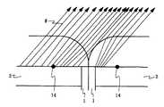
レンズからの出射光8のうち、目地近辺のものは、図のように左側へ向かって出射されるスクリーンからの出射光9がレンズ状スクリーン7により屈折されて平行光として出射される。これに対し、右側の部分からの出射光はレンズ状スクリーン7がその部分では平面なので何も影響されずスクリーン2からまっすぐに出射される。このように筐体1による目地から見かけ上出射する光が発生することが図からわかる。
【0013】
出射光8は画面を見ている人が受ける光であるため、この観視者にとって目地の見え方は、実際の目地の幅10がレンズ状スクリーン7の効果により見かけ状の幅11になっており、目地が狭くなったように見える。見かけ上どのくらい小さく見えるかはレンズの形状や大きさによって決まる。計算によると、レンズ状スクリーン7の曲線部の円形状の曲率半径が実際の目地の幅の大きさ10の数倍(だいたい5倍以上)であれば見かけ上の目地の幅の大きさ11は実際の幅の大きさ10の1/3以下になる。このように画面を見ている人には目地が目立たなくなるので目地による画質の劣化が気にならないレベルにまで減少させられる。
【0014】
本発明でのレンズの形状を図8に示す。図8(a)は前記曲線部が円形状の場合で、同図(b)は楕円形状の場合を示す。どちらも参照番号14で示してあるのが中心(楕円の場合は焦点)であり、破線より左側の部分が凸レンズ構造を構成している。また、本発明のレンズを斜めから見た場合の光の進み方を図9に示す。このように、ほとんど影になる部分は存在しないことがわかる。
【0015】
なお、図7からわかるように凸レンズ構造部分へ光が入射する領域16と凸レンズ構造部分から光が出射する領域17を比較すると、目地の部分だけ領域17が広くなっており、上記の大きさよりその比は1.2倍以下である。このため、領域16に表示される画像は1.2倍だけ拡大されて領域17に表示されるが、この程度であれば目地が目立つよりも影響がはるかに少ない。さらにデジタル信号処理を用いてあらかじめその部分に表示する画像を縮小しておけば(5画素から内挿して4画素を作る程度は現在の技術では容易である)影響を軽減できる。この場合、その部分の信号レベルを上げて輝度の補正も可能であるが、斜めから見たときに明るい部分が目立つこともあり得るので、輝度の補正は必ずしも必要ではない。
このようにレンズ構造を持つスクリーンを使用すると、マルチ画面で生じる画面の目地を目立たなくすることができる。
【0016】
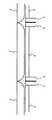
図10に、本発明の具体例1を示す。これは、両端が楕円形状のレンズ構造をなしスクリーンの幅(図10の矢印部分)が筐体1の幅と等しいレンズ状スクリーン7を各投射装置のスクリーンの上にのせたものである。なお、本発明であるレンズ状スクリーン7の固定は、スクリーン2に透明な接着剤や透明なネジなどで行うことができる。図10では透明なネジ18を使用した場合を示している。また図11のように透明板にスクリーン7を加工して製作しそれ全体をネジなどで筐体1に固定することも可能である。これを具体例2として図11に示す。
【0017】
図12は、本発明の具体例3を示している。凸レンズは逆方向に用いてもほぼ同じ効果が得られるので、観視者側の面をこのように平面にすることができる。図11と同じく透明板上にスクリーン7を加工して製作したものを具体例4として図13に示す。
【0018】
以上いくつかの具体例をあげ本発明の実施の形態を説明してきたが、本発明はこれらに限定されることなく、本発明の要旨内で各種の変形、変更の可能なことは自明であろう。
【0019】
【発明の効果】
マルチ画面は大画面を実現する上で多く利用されている技術である。本発明により、画面の目地が目立たない大画面ディスプレイを実現できる。
【図面の簡単な説明】
【図1】 投射型ディスプレイの構成例である。
【図2】 (a)はマルチ投射型ディスプレイ構成例の側面図、(b)はその正面図である。
【図3】 図2で目地の部分の拡大図である。
【図4】 目地の部分の不自然さを抑圧する従来例である。
【図5】 図4の一部分を拡大した図である。
【図6】 透明なスクリーン枠を設けた従来例である。
【図7】 本発明の原理を説明するための図である。
【図8】 (a)および(b)は本発明でのそれぞれ異なった2つのレンズ構造図である。
【図9】 本発明で斜めから見た場合の例を示す図である。
【図10】 本発明の具体例1である。
【図11】 本発明の具体例2である。
【図12】 本発明の具体例3である。
【図13】 本発明の具体例4である。
【符号の説明】
1 筐体
2 スクリーン
3 投射装置
4 目地の部分
5 投射装置からの入射光
6 スクリーンからの出射光
7 レンズ状スクリーン
8 観視者からみたレンズからの出射光
9 レンズで屈折されるスクリーンからの出射光
10 実際の目地の幅
11 見かけ上の目地の幅
12 凸レンズ構造
13 凸レンズ構造に光が入る領域
14 凸レンズ構造の曲線部の中心位置
15 透明スクリーン取り付け枠
16 凸レンズ構造部分へ光が入射する領域
17 凸レンズ構造部分から光が出射する領域
18 透明ネジ[0001]
BACKGROUND OF THE INVENTION
The present invention relates to a multi-projection screen that displays a large screen by arranging a plurality of screens.
[0002]
[Prior art]
There is a multi-screen as means for configuring a large-screen display. For example, a plurality of projection displays shown in FIG. 1 are stacked vertically and horizontally as shown in FIG. 2 to form a display having a large screen as a whole. The projection type display includes a projection device 3 in a
[0003]
[Problems to be solved by the invention]
As described above, a large screen can be easily configured by a multi-screen, but a problem is that a line 4 as shown in FIG. 2B can be seen in the screen. This is because light is not emitted from a portion corresponding to the thickness of the
[0004]
As a method for solving this problem, there is a method of providing a
[0005]
However, there are limitations on the convex lens structure. This will be described with reference to FIG. In FIG. 5, since the light from the “region where light enters the convex lens structure” 13 has to go in both the light exit directions A and B (otherwise it becomes dark and the joints are clearly visible), the
[0006]
Further, since the light output from the
As described above, the convex lens structure has a little effect of improving the appearance of joints or is easily damaged.
[0007]
In addition to this, it has been devised to provide a transparent
[0008]
Accordingly, an object of the present invention is to provide a multi-projection type screen in which the multi-screen joints that are conspicuous as described above are made inconspicuous.
[0009]
[Means for Solving the Problems]
To this end, the present invention multi-projection screen, the screen blocks the screen on which an image is projected is attached to the front in the multi-projection screento form a large screen stacked in multiple stages,the screen block The parallel flat screen on which an image is projected and the center form a flat lens structure covering the central portion of the parallel flat screen, and the periphery covers the joint portion between the parallel flat screens and the peripheral portion of the parallel flat screen. A convex lens structure, and a lens-shaped transparent screen mounted on the light exit side of the parallel flat screen, and the convex lens structure forming the periphery of the lens-shaped transparent screen has a curved portion of the cross-sectional shape forming the center. Inclined in a circular or elliptical shape from the viewer side of the flat lens toward the joint, and the joint part Width so that narrows when viewed from the viewer, is characterized inthat emitted by refracting light emitted from the parallel plate screen.
[0010]
Further, preferred embodiments of the invention, the width curved portion of the cross-sectional shape of the convex lens structure in a screen according to
[0011]
Further, in a preferred embodiment, the curved portion of the cross-sectional shape of the convex lens structure is an elliptical shape, wherein half of the major axis of the elliptical ellipse is a width viewed from the light incident side of the joint portion. It is characterized in that it isat least five times the size of.Here, the above-mentioned at least 5 times means 5 times or more.
[0012]
Out of the light 8 emitted from the lens, the light in the vicinity of the joint is refracted by the lens-
[0013]
Since the emitted light 8 is light received by a person watching the screen, the appearance of the joints for this viewer is that the
[0014]
The shape of the lens in the present invention is shown in FIG. FIG. 8A shows a case where the curved portion is circular, and FIG. 8B shows a case where the curved portion is elliptic. In both cases, the
[0015]
As can be seen from FIG. 7, when comparing the
When the screen having the lens structure is used as described above, the joints of the screen generated in the multi-screen can be made inconspicuous.
[0016]
FIG. 10 shows Example 1 of the present invention. This is a lens structure in which both ends have an elliptical lens structure and the width of the screen (the arrow portion in FIG. 10) is equal to the width of the
[0017]
FIG. 12 shows a third specific example of the present invention. Since the same effect can be obtained even if the convex lens is used in the opposite direction, the surface on the viewer side can be made flat in this way. FIG. 13 shows a fourth embodiment obtained by processing the
[0018]
Although the embodiments of the present invention have been described with some specific examples, the present invention is not limited to these, and it is obvious that various modifications and changes can be made within the scope of the present invention. Let's go.
[0019]
【The invention's effect】
Multi-screen is a technology that is widely used to realize a large screen. According to the present invention, it is possible to realize a large screen display in which the screen joint is not conspicuous.
[Brief description of the drawings]
FIG. 1 is a configuration example of a projection display.
2A is a side view of a configuration example of a multi-projection display, and FIG. 2B is a front view thereof.
FIG. 3 is an enlarged view of a joint portion in FIG. 2;
FIG. 4 is a conventional example for suppressing unnaturalness of a joint portion.
5 is an enlarged view of a part of FIG.
FIG. 6 is a conventional example in which a transparent screen frame is provided.
FIG. 7 is a diagram for explaining the principle of the present invention.
FIGS. 8A and 8B are structural diagrams of two different lenses in the present invention, respectively.
FIG. 9 is a diagram showing an example when viewed from an oblique direction according to the present invention.
FIG. 10 is a specific example 1 of the present invention.
FIG. 11 is a second specific example of the present invention.
FIG. 12 is a third specific example of the present invention.
FIG. 13 is a fourth specific example of the present invention.
[Explanation of symbols]
DESCRIPTION OF
Claims (3)
Translated fromJapanese前記スクリーンブロックが、
画像が投射される平行平板スクリーンと、
中央が、前記平行平板スクリーンの中央部分を覆う平板レンズ構造を成し、周辺が、前記平行平板スクリーン間の目地部分及び平行平板スクリーンの周辺部分を覆う凸レンズ構造を成し、前記平行平板スクリーンの光出射側に装着したレンズ状透明スクリーンとを備え、
前記レンズ状透明スクリーンの周辺を成す凸レンズ構造は、その断面形状の曲線部が、前記中央を成す平板レンズの観視者側の箇所から目地へ向けて円形状または楕円形状に傾斜し、目地部分の幅が観視者から見て狭くなるように、平行平板スクリーンからの出射光を屈折させて出射することを特徴とするマルチ投射型スクリーン。Inthe multi-projection type screen that formsa large screen by stacking screen blocks on which the screen on which the image is projected is mounted on the front surfacein multiple stages,
The screen block is
A parallel flat screen on which an image is projected;
The center forms a flat lens structure that covers the central portion of the parallel flat screen, and the periphery forms a convex lens structure that covers the joint portion between the parallel flat screens and the peripheral portion of the parallel flat screen. With a lens-like transparent screen mounted on the light exit side,
The convex lens structure that forms the periphery of the lenticular transparent screen has a curved portion whose cross-sectional shape is inclined in a circular or elliptical shape from the viewer side of the flat lens that forms the center toward the joint, and the joint portion A multi-projection screen characterizedin that thelight emitted from the parallel flat screen is refracted and emitted so thatthe width of the screen becomes narrower as viewed from the viewer .
前記円形状の曲率半径が、目地部分の光入射側からみた幅の大きさの少なくとも5倍であることを特徴とするマルチ投射型スクリーン。The screen according to claim 1, wherein the curved portion of the cross-sectional shape of the convex lens structure is circular.
Multi-projection screen, characterized in that the circular radius of curvatureis atleast five times the size of a width as viewed from the light incident side of the joint portion.
前記楕円形状の楕円の長径の半分が、目地部分の光入射側からみた幅の大きさの少なくとも5倍であることを特徴とするマルチ投射型スクリーン。The screen according to claim 1, wherein the curved portion of the cross-sectional shape of the convex lens structure is elliptical.
A multi-projection screen, wherein half of the major axis of the elliptical ellipse isat least five times the width of the joint viewed from the light incident side.
Priority Applications (1)
| Application Number | Priority Date | Filing Date | Title |
|---|---|---|---|
| JP36206598AJP3762123B2 (en) | 1998-12-21 | 1998-12-21 | Multi-projection type screen |
Applications Claiming Priority (1)
| Application Number | Priority Date | Filing Date | Title |
|---|---|---|---|
| JP36206598AJP3762123B2 (en) | 1998-12-21 | 1998-12-21 | Multi-projection type screen |
Publications (2)
| Publication Number | Publication Date |
|---|---|
| JP2000180964A JP2000180964A (en) | 2000-06-30 |
| JP3762123B2true JP3762123B2 (en) | 2006-04-05 |
Family
ID=18475797
Family Applications (1)
| Application Number | Title | Priority Date | Filing Date |
|---|---|---|---|
| JP36206598AExpired - Fee RelatedJP3762123B2 (en) | 1998-12-21 | 1998-12-21 | Multi-projection type screen |
Country Status (1)
| Country | Link |
|---|---|
| JP (1) | JP3762123B2 (en) |
Cited By (4)
| Publication number | Priority date | Publication date | Assignee | Title |
|---|---|---|---|---|
| CN102598093A (en)* | 2009-11-12 | 2012-07-18 | 夏普株式会社 | Display unit and display device |
| CN103529633A (en)* | 2013-11-04 | 2014-01-22 | 广东威创视讯科技股份有限公司 | Connection piece structure for connecting joint screens |
| WO2016127604A1 (en)* | 2015-02-10 | 2016-08-18 | 京东方科技集团股份有限公司 | Display panel and display device |
| US10885875B2 (en) | 2018-03-29 | 2021-01-05 | Au Optronics Corporation | Seamless or frameless display device having lens layer |
Families Citing this family (24)
| Publication number | Priority date | Publication date | Assignee | Title |
|---|---|---|---|---|
| GB0028890D0 (en)* | 2000-11-27 | 2001-01-10 | Isis Innovation | Visual display screen arrangement |
| JP4701735B2 (en)* | 2004-07-09 | 2011-06-15 | 株式会社豊田自動織機 | Sliding member |
| JP5200930B2 (en)* | 2006-04-07 | 2013-06-05 | 日本電気株式会社 | Image display device |
| JP2007307252A (en)* | 2006-05-19 | 2007-11-29 | Daiichi Shokai Co Ltd | Game machine |
| WO2008149449A1 (en)* | 2007-06-07 | 2008-12-11 | Telesystems Co., Ltd. | Multi-display device |
| CN101868814B (en) | 2007-11-22 | 2013-06-05 | 夏普株式会社 | Display device |
| WO2009157161A1 (en)* | 2008-06-26 | 2009-12-30 | シャープ株式会社 | Display device and electronic device |
| JP5490710B2 (en)* | 2008-10-24 | 2014-05-14 | シャープ株式会社 | Display device and driving method of display device |
| EP2398005A4 (en)* | 2009-02-10 | 2013-10-09 | Sharp Kk | Display device and method of manufacturing same |
| KR101549257B1 (en)* | 2009-03-11 | 2015-09-01 | 엘지전자 주식회사 | Display device |
| WO2010122618A1 (en)* | 2009-04-24 | 2010-10-28 | シャープ株式会社 | Display apparatus, display method, display control program, and recording medium |
| US20110267541A1 (en)* | 2009-04-28 | 2011-11-03 | Sharp Kabushiki Kaisha | Display apparatus |
| EP2437250B1 (en) | 2009-05-29 | 2015-07-22 | Sharp Kabushiki Kaisha | Display device and method of driving display device |
| WO2011001933A1 (en)* | 2009-07-01 | 2011-01-06 | シャープ株式会社 | Display device |
| US9285533B2 (en) | 2011-01-13 | 2016-03-15 | Sharp Kabushiki Kaisha | Display apparatus |
| CN103518233B (en)* | 2011-05-11 | 2016-08-31 | 夏普株式会社 | The manufacture method of display device, multi-display system and display device |
| WO2013008776A1 (en)* | 2011-07-13 | 2013-01-17 | シャープ株式会社 | Display device and multi display system |
| DK2728570T3 (en)* | 2012-03-26 | 2016-11-21 | Dainippon Printing Co Ltd | Display apparatus of the array-type |
| WO2015033408A1 (en)* | 2013-09-04 | 2015-03-12 | 株式会社東芝 | Display device, display system, and display method |
| WO2015033452A1 (en)* | 2013-09-06 | 2015-03-12 | 株式会社東芝 | Image display system and image display method |
| KR101426726B1 (en)* | 2013-11-22 | 2014-08-05 | 방채원 | Multi-screen dispaly device having a transparent cover of invisible bezel |
| CN104123885A (en)* | 2014-07-15 | 2014-10-29 | 青岛海信电器股份有限公司 | Seamless splicing display device |
| JP6905342B2 (en)* | 2017-01-24 | 2021-07-21 | 三菱鉛筆株式会社 | Stationery |
| JP6312887B1 (en)* | 2017-03-24 | 2018-04-18 | 山佐株式会社 | Display unit for gaming machine and gaming machine |
- 1998
- 1998-12-21JPJP36206598Apatent/JP3762123B2/ennot_activeExpired - Fee Related
Cited By (5)
| Publication number | Priority date | Publication date | Assignee | Title |
|---|---|---|---|---|
| CN102598093A (en)* | 2009-11-12 | 2012-07-18 | 夏普株式会社 | Display unit and display device |
| CN102598093B (en)* | 2009-11-12 | 2015-01-07 | 夏普株式会社 | Display device |
| CN103529633A (en)* | 2013-11-04 | 2014-01-22 | 广东威创视讯科技股份有限公司 | Connection piece structure for connecting joint screens |
| WO2016127604A1 (en)* | 2015-02-10 | 2016-08-18 | 京东方科技集团股份有限公司 | Display panel and display device |
| US10885875B2 (en) | 2018-03-29 | 2021-01-05 | Au Optronics Corporation | Seamless or frameless display device having lens layer |
Also Published As
| Publication number | Publication date |
|---|---|
| JP2000180964A (en) | 2000-06-30 |
Similar Documents
| Publication | Publication Date | Title |
|---|---|---|
| JP3762123B2 (en) | Multi-projection type screen | |
| JP2951202B2 (en) | 3D display without glasses | |
| US6714349B2 (en) | Screen and projection display system with improved viewing angle characteristic | |
| JPH04296841A (en) | Large screen projection type display | |
| JPH1031102A (en) | Fresnel lens sheet and transmission screen | |
| JP2000112035A (en) | Projection type image display device and screen used therefor | |
| JPH0519346A (en) | Projection type image display device | |
| JP3789408B2 (en) | Reflective screen | |
| JP2003157031A (en) | Multi-display device | |
| JP2888297B2 (en) | projector | |
| US7061676B2 (en) | Rear projection screen and rear projection display apparatus | |
| CN2280931Y (en) | High-brightness film-television projection screen | |
| JPH0563781B2 (en) | ||
| JPH03220542A (en) | Transmission type screen | |
| JP2973594B2 (en) | Projection image display | |
| US7290883B2 (en) | System and method for projecting video onto a screen | |
| JPS6160636B2 (en) | ||
| JPH05333437A (en) | Rear projection television | |
| JP3797888B2 (en) | Transmission type screen and projection type image display apparatus using the same | |
| KR100649556B1 (en) | Screen with enhanced viewing angle characteristics and projection display system with this screen | |
| JPS5868382A (en) | Television picture projecting device | |
| JP2005148553A (en) | Transmission screen and rear projection display device | |
| JPH06202231A (en) | Screen for rear projection display | |
| JPS6330837A (en) | Transparent screen | |
| KR0149583B1 (en) | Liquid crystal project device |
Legal Events
| Date | Code | Title | Description |
|---|---|---|---|
| RD04 | Notification of resignation of power of attorney | Free format text:JAPANESE INTERMEDIATE CODE: A7424 Effective date:20040113 | |
| A621 | Written request for application examination | Free format text:JAPANESE INTERMEDIATE CODE: A621 Effective date:20040415 | |
| A977 | Report on retrieval | Free format text:JAPANESE INTERMEDIATE CODE: A971007 Effective date:20050920 | |
| A131 | Notification of reasons for refusal | Free format text:JAPANESE INTERMEDIATE CODE: A131 Effective date:20051004 | |
| A521 | Written amendment | Free format text:JAPANESE INTERMEDIATE CODE: A523 Effective date:20051202 | |
| TRDD | Decision of grant or rejection written | ||
| A01 | Written decision to grant a patent or to grant a registration (utility model) | Free format text:JAPANESE INTERMEDIATE CODE: A01 Effective date:20051220 | |
| A61 | First payment of annual fees (during grant procedure) | Free format text:JAPANESE INTERMEDIATE CODE: A61 Effective date:20060112 | |
| R150 | Certificate of patent or registration of utility model | Free format text:JAPANESE INTERMEDIATE CODE: R150 | |
| FPAY | Renewal fee payment (event date is renewal date of database) | Free format text:PAYMENT UNTIL: 20100120 Year of fee payment:4 | |
| FPAY | Renewal fee payment (event date is renewal date of database) | Free format text:PAYMENT UNTIL: 20110120 Year of fee payment:5 | |
| LAPS | Cancellation because of no payment of annual fees |