JP3762025B2 - Ophthalmic examination equipment - Google Patents
Ophthalmic examination equipmentDownload PDFInfo
- Publication number
- JP3762025B2 JP3762025B2JP06249797AJP6249797AJP3762025B2JP 3762025 B2JP3762025 B2JP 3762025B2JP 06249797 AJP06249797 AJP 06249797AJP 6249797 AJP6249797 AJP 6249797AJP 3762025 B2JP3762025 B2JP 3762025B2
- Authority
- JP
- Japan
- Prior art keywords
- blood vessel
- mirror
- tracking
- light
- output
- Prior art date
- Legal status (The legal status is an assumption and is not a legal conclusion. Google has not performed a legal analysis and makes no representation as to the accuracy of the status listed.)
- Expired - Fee Related
Links
Images


Landscapes
- Measuring Pulse, Heart Rate, Blood Pressure Or Blood Flow (AREA)
- Eye Examination Apparatus (AREA)
Description
Translated fromJapanese【0001】
【発明の属する技術分野】
本発明は、眼底上の血管を検査する眼底検査装置に関するものである。
【0002】
【従来の技術】
従来から、被検眼の眼底上の血管の動きをトラッキングする眼科検査装置としては、例えば特開昭63−288133号公報に記載されているように、2個所の血管の動きを検出して二次元的にトラッキングを行う装置や、特表平6−503733号公報に記載されているように、1個所の血管の走行方向に垂直な動きを検出して一次元的にトラッキングを行う装置等が知られている。
【0003】
これらの眼科検査装置では、トラッキング光の眼底での反射光を受光する受光手段として一次元CCDを使用し、血管像信号の波形処理を行って、トラッキング中心位置と血管像の位置の偏移量を算出し、トラッキングを行っている。このとき、血管像信号のレベルを最適化するために、一次元CCDの出力信号のレベルが設定範図内となるように、手動又は自動で増幅器の増幅率を電気的に調整したり、一次元CCDの前に置かれたイメージ・インテンシファイヤによる一次元CCDへの入射光量の増幅率を、同様の方法で調整している。
【0004】
また、移動物体の一次元CCDに対する相対位置を検出し、撮像方向を変える撮像方向変更手段に、この位置信号を絶えずフィードバックすることにより、物体の追尾捕捉を可能とする装置が提案されている。
【0005】
【発明が解決しようとする課題】
しかしながら上述の従来例において、増幅器の増幅率を電気的に調整する方法や、イメージ・インテンシファイヤによる一次元CCDへの入射光量の増幅率を調整する方法は、血管でない眼底上の明るい部分が飽和しないように増幅率を調整しているために、コントラストの小さい細い血管の波形信号レベルが極めて小さくなり、良好にトラッキングができない場合がある。
【0006】
また、実際の測定の際には、患者の眼球は完全に静止していることはなく、固視の最中に微動を繰り返しているので、この微動に対してレーザー光を追従させなければならない。しかし、コントラストの大きい太い血管と、コントラストの小さい細い血管が近接している場合には、固視微動等の眼球運動によって、コントラストの大きい太い血管がトラッキング中心位置に近付いたときに、トラッキングを掛けたいコントラストの小さい細い血管よりも、太い血管の方にトラッキングが掛かってしまうという問題点がある。
【0007】
更に、物体の追尾補捉を可能とする装置においても、血管位置を抽出するまでの信号処理方法が開示されていない。
【0008】
本発明の目的は、上述の問題点を解消し、所望の眼底血管に対して正確にかつ安定してトラッキングを掛ける眼科検査装置を提供することにある。
【0009】
【課題を解決するための手段】
上記目的を達成するための本発明に係る眼科検査装置は、ターゲットの血管を繰り返し撮像することでトラッキングする眼科検査装置であって、前記ターゲットの血管を照明する照明手段と、ターゲットの血管を含む眼底像を映像信号に変換するための撮像手段と、前記映像信号から前記ターゲットの血管の径を算出する演算手段と、前記ターゲットの血管の位置及び血管径から、次撮像における前記撮像手段の増幅率を決定するための前記映像信号の範囲を決定する正規化処理範囲設定手段と、前記範囲内における前記ターゲットの血管の映像信号値から、前記ターゲットの血管の映像信号値に応じて次撮影で使用する前記撮像手段の増幅率を決定する処理条件決定手段とを備えることを特徴とする。
【0011】
【発明の実施の形態】
本発明を図示の実施例に基づいて詳細に説明する。
図1は第1の実施例の眼底血流計の構成図を示し、白色光を発するタングステンランプ等から成る観察用光源1から被検眼Eに対向する対物レンズ2に至る照明光路上には、コンデンサレンズ3、例えば黄色域の波長光のみを透過するバンドパスフィルタ付フィールドレンズ4、被検眼Eの瞳孔Epとほぼ共役なリングスリット5、被検眼Eの水晶体とほほ共役な遮光部材6、リレーレンズ7、光路に沿って移動自在な固視標表示用素子である透過型液晶板8、リレーレンズ9、被検眼Eの角膜近傍と共役な遮光部材10、孔あきミラー11、黄色域の波長光を透過し他の光束を殆ど反射するバンドパスミラー12が順次に配列されている。
【0012】
孔あきミラー11の背後には眼底観察光学系が構成されており、光路に沿って移動自在なフォーカスレンズ13、リレーレンズ14、スケール板15、光路中に挿脱自在な光路切換ミラー16、接眼レンズ17が順次に配列され、検者眼eに至っている。また、光路切換ミラー16が光路中に挿入されているときの反射方向の光路上には、テレビリレーレンズ18、CCDカメラ19が配置されており、CCDカメラ19の出力は液晶モニタ20に接続されている。
【0013】
バンドパスミラー12の反射方向の光路上には、イメージローテータ21、紙面に垂直な回転軸を有する両面研磨されたガルバノメトリックミラー22が配置され、ガルバノメトリツクミラー22の下側反射面22aの反射方向には、光路に沿って移動自在な第2のフォーカスレンズ23が配置され、上側反射面22bの反射方向には、レンズ24、光路に沿って移動自在なフォーカスユニット25が配置されている。なお、レンズ24の前側焦点面は被検眼Eの瞳孔Epと共役関係にあり、この焦点面にガルバノメトリツクミラー22が配置されている。
【0014】
また、ガルバノメトリツクミラー22の後方には、光路長補償半月板26、光路中に遮光部を有する黒点板27、凹面ミラー28が光路上に同心に配置され、ガルバノメトリックミラー22の下側反射面22aで反射されず通過する光束を、ガルバノメトリックミラー22の上側反射面22bへ導くリレー光学系が構成されている。なお、光路長補正用半月板26は、ガルバノメトリックミラー22の上側反射面22b及び下側反射面22aの位置が、そのミラー厚によって生ずる図面上下方向へずれを持つことを補正するためのものであり、イメージローテータ21へ向かう光路中にのみ作用するものである。
【0015】
フォーカスユニット25においては、レンズ24と同一光路上に、ダイクロイックミラー29、集光レンズ30が配置され、ダイクロイックミラー29の反射方向の光路上には、整形用マスク31、ミラー32が配置されており、このフォーカスユニット25は一体的に光路に沿って矢印で示す方向に移動できるようになっている。
【0016】
集光レンズ30の入射方向の光路上には、固定ミラー33、光路から退避可能な光路切換ミラー34が平行に配置され、光路切換ミラー34の入射方向の光路上には、コリメータレンズ35、コヒーレントな例えば赤色光を発する測定用のレーザーダイオード36が配置されている。更に、ミラー32の入射方向の光路上には、シリンドリカルレンズ等から成るビームエクスパンダ37、高輝度の他の光源と異なる例えば緑色光を発するトラッキング用光源38が配置されている。
【0017】
第2のフォーカスレンズ23の後方の光路上には、ダイクロイツクミラー39、フィールドレンズ40、拡大レンズ41、イメージインテンシファイヤ付一次元CCD42が順次に配列され、血管検出系が構成されている。また、ダイクロイックミラー39の反射方向の光路上には、結像レンズ43、共焦点絞り44、被検眼Eの瞳孔Epとほぼ共役なミラー対45a、45bが配列され、ミラー対45a、45bの反射方向にはそれぞれフォトマルチプライヤ46a、46bが配列され、測定用受光光学系が構成されている。
【0018】
なお、図示の都合上、全ての光路を同一平面上に示したが、レーザーダイオード36からマスク31に至る光路、トラッキング用光源38の出射方向の測定光路、ミラー対45a、45bの反射光路はそれぞれ紙面に直交している。
【0019】
更に、装置全体を制御するためのシステム制御部47が設けられ、システム制御部47には一次元CCD42の出力、フォトマルチプライヤ46a、46bの出力がそれぞれ接続されており、システム制御部47の出力はガルバノメトリックミラー22、光路切換ミラー34にそれぞれ接続されている。
【0020】
図2はシステム制御部の構成図を示し、一次元CCD42の出力は増幅器50、サンプルホールド回路51に順次に接続され、サンプルホールド回路51の出力は、ピークホールド回路52、反転バッファ53にそれぞれ接続されている。ピークホールド回路52、反転バッファ53の出力はそれぞれ加算回路54に接続され、加算回路54の出力はローパスフィルタ55に接続されている。ローパスフィルタ55の出力はピークホールド回路56、割算部57に接続され、ピークホールド回路56の出力はサンプルホールド回路58を介してA/D変換器59に接続されている。
【0021】
A/D変換器59はバスラインを通じてI/Oインタフェイス60、メモリ61、MPU62、D/A変換器63のそれぞれに接続されており、D/A変換器63の出力は、割算部57に接続されている。更に、割算部57の出力は微分回路64に接続され、ゼロクロス比較部65を通じて血管位置演算部66に接続されている。また、血管位置演算部66にはI/Oインタフェイス60からの出力も接続され、血管位置演算部66の出力は、ガルバノメトリックミラー制御部67を介してガルバノメトリックミラー22に接続されている。
【0022】
また、クロックパルス発生器68の出力がMPU62、タイミング生成部69に接続されており、タイミング生成部69の出力は一次元CCD42、サンプルホールド回路51、58、ピークホールド回路52、56、割算部57に接続され、I/Oインタフェイス60の出力は光路切換ミラー34に接続され、入力部70の出力がI/Oインタフェイス60に接続されている。
【0023】
増幅器50、サンプルホールド回路51、58、ピークホールド回路52、56、反転バッファ53、加算回路54、割算部57、微分回路64により、血管部位抽出部71が構成され、ピークホールド回路56、割算部57、サンプルホールド回路58により、ACG(Automatic gain control)部72が構成されている。また、A/D変換器63、I/Oインタフェイス60、メモリ61、MPU62、D/A変換器63により、処理条件決定部73が構成され、ゼロクロス比較部65、血管位置演算部66、ガルバノメトリックミラー制御部67により、自動追尾制御部74が構成されている。
【0024】
図3は被検眼Eの瞳孔Ep上の各光束の配置を示し、Iは黄色の照明光により照明される領域でリングスリット5の像、Oは眼底観察光束で孔あきミラー11の開口部の像、Vは測定/血管受光光束でガルバノメトリックミラー22の上下反射面の有効部の像、Da、Dbは2つの測定受光光束それぞれミラー対45a、45bの像である。P2、P2' は測定光の入射位置で、光路切換ミラー34を切換えることによって選択される測定光の位置を示し、鎖線で示す領域Mはガルバノメトリックミラー22の下側反射面22aの像である。
【0025】
観察用光源1から発した白色光はコンデンサレンズ3を通り、バンドパスフィルタ付フィールドレンズ4により黄色の波長光のみが透過され、リングスリット5、遮光部材6、リレーレンズ7を通り、透過型液晶板8を背後から照明し、リレーレンズ9、遮光部材10を通って孔あきミラー11で反射され、黄色域の波長光のみがバンドパスミラー12を透過し、対物レンズ2を通って被検眼Eの瞳孔Ep上で眼底照明光による光束像Iとして一旦結像した後に、眼底Eaをほぼ一様に照明する。
【0026】
このとき、透過型液晶板8には固視標が表示されており、照明光により被検眼Eの眼底Eaに投影され、視標像として被検眼Eに呈示される。なお、リングスリット5、遮光部材6、10は、被検眼Eの前眼部において眼底照明光と眼底観察光を分離するためのものであり、必要な遮光領域を形成するものであればその形状は問題とならない。
【0027】
眼底Eaからの反射光は同じ光路を戻り、瞳孔Ep上から眼底観察光光束Oとして取り出され、孔あきミラー11の中心の開口部、フォーカスレンズ13、リレーレンズ14を通り、スケール板15で眼底像Ea’として結像した後に、光路切換ミラー16に至る。
【0028】
ここで、光路切換ミラー16が光路から退避しているときは、検者眼eにより接眼レンズ17を介して眼底像Ea’が観察可能となり、一方、光路切換ミラー16が光路に挿入されているときは、スケール板15上に結像した眼底像Ea’がテレビリレーレンズ18によりCCDカメラ19上に再結像し、液晶モニタ20に映出される。この眼底像Ea’を観察しながら接眼レンズ17又は液晶モニタ20により装置のアライメントを行う。
【0029】
レーザーダイオード36を発した測定光は、コリメータレンズ35によりコリメートされ、光路切換ミラー34が光路に挿入されている場合には、光路切換ミラー34、固定ミラー33でそれぞれ反射され、集光レンズ30の下方を通過し、光路切換ミラー34が光路から退避している場合には、直接集光レンズ30の上方を通過し、ダイクロイックミラー29を透過する。
【0030】
一方、トラッキング用光源38から発したトラッキング光は、ビームエクスパンダ37により縦横異なる倍率でビーム径が拡大され、ミラー32で反射された後に整形用マスク31で所望の形状に整形されて、ダイクロイックミラー29に反射され、整形用マスク31の開口部中心と共役な位置にスポット状に結像している測定光と、集光レンズ30により重量される。
【0031】
この測定光とトラッキング光はレンズ24を通り、ガルバノメトリックミラー22の上側反射面22bで一旦反射され、黒点板27を通った後に凹面鏡48で反射され、再び黒点板27、光路長補正用半月板26を通りガルバノメトリックミラー22の方へ戻される。
【0032】
ここで、ガルバノメトリックミラー22の上方に配置されたリレー光学系により、ガルバノメトリックミラー22の上側反射面22bと下側反射面22aとを−1倍で結像する機能が与えられているので、光路切換ミラー34の光路中への挿入・退避により、ダイクロイックミラー22の像Mの裏側の図3のP1、P1' の何れかの位置で反射された測定光とトラッキング光は、今度はダイクロイックミラー22の切欠き部に位置するP2、P2' の位置へ戻されることになり、ダイクロイックミラー22で反射されることなくイメージローテータ21へ向う。そして、イメージローテータ21を経て、バンドパスミラー12により対物レンズ2方向へ偏向された測定光とトラッキング光は、対物レンズ2を介して被検眼Eの眼底Eaに照射される。
【0033】
このように、測定光とトラッキング光はガルバノメトリックミラー22の上側反射面22b内で反射され、再び戻されるときは対物レンズ2の光軸から偏心した状態でガルバノメトリックミラー22に入射が行われ、その結果として図3に示すように瞳孔Ep上でスポット像P2又はP2' として結像した後に、眼底Eaを点状に照射する。
【0034】
眼底Eaでの散乱反射光は再び対物レンズ2で集光し、バンドパスミラー12で反射されイメージローテータ21を通り、ガルバノメトリックミラー22の下側反射面22aで反射され、フォーカスレンズ23を通りダイクロイックミラー39において両光束が分離される。トラッキング光はダイクロイックミラー39を透過し、フィールドレンズ40、結像レンズ41により、一次元CCvとして結像する。
【0035】
また、両光束による眼底Eaでの散乱反射光の一部はバンドパスミラー12を透過し、孔あきミラー11の背後の眼底観察光学系に導かれる。ここで、トラッキング光はスケール板15上に棒状のインジケータTとして結像し、測定光はこのインジケータTの中心部にスポット像として結像する。これらの像は接眼レンズ17又は液晶モニタ20を介して眼底像Ea’及び視標像と共に観察される。このとき、インジケータTの中心には図示しないスポット像が重畳して観察されており、インジケータTは入力部70の操作桿等の操作部材により、眼底Ea上を一次元に移動することができる。
【0036】
検者は先ず眼底像Ea’のピント合わせを行う。入力部70のフォーカスノブを調整すると、図示しない駆動手段により透過型液晶板8、フォーカスレンズ13、23、フォーカスユニット25が連動して光路に沿って移動する。眼底像Ea’のピントが合うと、透過型液晶板8、スケール板15、一次元CCD42、共焦点絞り44は同時に眼底Eaと共役になる。検者は眼底像Ea’上のフォーカス状態を見ながら、測定対象となる血管Evの深さを設定し、眼底像Ea’のピントを合わせる。
【0037】
ピント合わせが終了した後に、検者は被検眼Eの視線を誘導して観察領域を変更し、入力部70を操作して測定対象とする血管Evを適当な位置へ移動する。システム制御部47は透過型液晶板8を制御する制御回路を駆動して視標像を移動する。そして、入力部70の操作桿を操作してインジケータTを回転し、測定対象とする血管Evの走行方向に対してインジケータTが垂直になるようにする。システム制御部47はイメージローテータ21を制御する制御回路を駆動し、イメージローテータ21を駆動してインジケータTを回転する。
【0038】
検者はトラッキングを確認した後に、入力部70の測定スイッチを押して測定を開始する。測定光はダイクロイックミラー39により反射され、共焦点絞り44の開口部を経てミラー対45a、45bで反射され、それぞれフォトマルチプライヤ46a、46bに受光される。フォトマルチプライヤ46a、46bの出力はそれぞれシステム制御部47に出力され、この受光信号は周波数解析されて眼底Eaの血流速度が求められる。
【0039】
先ず、図4に示すようにトラッキングをすべき血管Ev1 の周囲に血管Evが無い場合は、検者がトラッキングを開始すると、一次元CCD42で撮像された血管像Ev' はタイミング生成部69で生成されたタイミングで読み出され、増幅器50で増幅される。増幅器50の出力信号はサンプルホールド回路51で、タイミング生成部69で生成されたタイミングでサンプルホールドされる。血管Evの部分は暗く、血管Evの周辺部分は明るいために、図5(d) に示すような波形を出力する。ここで、出力レベルが高い部分は明るい部位を示している。
【0040】
サンプルホールド回路51の出力信号はピークホールド回路52に入力され、タイミング生成部69よって生成された図5(a) のLレベルの期間のみピークホールドを行い、それ以外の期間は入力信号をそのまま出力する。ピークホールド回路52の出力と、サンプルホールド回路51の出力を反転バッファ53で反転した信号とが加算回路54に入力され、加算されて図5(e) に示すように血管像信号だけが抽出される。加算回路54の出力はローパスフィルタ55に入力されて図5(g) に示すように高周波成分がカットされる。
【0041】
ローパスフィルタ55の出力はピークホールド回路56に入力され、図5(b) のLレベルの期間のみピークホールドを行い、サンプルホールド回路58に入力される。サンプルホールド回路58は図5(c) のLレベルの期間でサンプリングを行い、Hレベルの期間でホールドする。サンプルホールド回路58の出力信号は、図5(f) にローパスフィルタ55の出力波形と共に示してあり、A/D変換器59に入力されてデジタルデータに変換され、MPU62で演算処理を行った後に、D/A変換器63から次のサンプル周期での血管位置検出用のAGCゲインとして出力される。
【0042】
図5にはMPU62がA/D変換器59に入力した信号レベルをそのままD/A変換器63に設定した場合の波形を示している。D/A変換器63の出力波形は血管位置検出のためのAGCゲインとして、ローパスフィルタ55の出力波形はトラッキング用の信号波形として、それぞれ割算部57へ入力され、割算部57では(ローパスフィルタ55の出力信号)÷(D/A変換器63の出力信号)の演算を行い、トラッキングをすべき血管信号に対して期間Aのサンプリングで血管位置検出のためのAGCを掛ける。
【0043】
図5(h) に示す割算部57の出力信号は微分回路64で微分され、更に微分回路64の出力は、ゼロクロス比較部65に入力されて約0Vと比較され、その出力は血管位置信号として図5(i) に示すように出力される。この血管位置信号はI/Oインタフェイス60から出力されるトラッキング中心位置信号と血管位置演算部66で比較され、トラッキング中心に最も近い血管の偏移量をガルバノメトリックミラー制御部67に出力する。ガルバノメトリックミラー制御部67はこの偏移量を補償するようにガルバノメトリックミラー22を駆動する。
【0044】
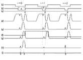
次に、図6に示すようにトラッキングを掛けるべき血管Ev2 の周囲に、血管Ev2 よりもコントラストの高い血管Ev3 が存在する場合を、図7に示す出力波形を基に説明する。MPU62がA/D変換器59に入力した信号レベルをそのままD/A変換器63に設定した場合には、n=0のサンプル周期では血管Ev2 のトラッキング中心からの偏移量dの方が、血管Ev3 のトラッキング中心からの偏移量d’よりも小さいために、血管位置演算部66はトラッキング中心に最も近い血管の偏移量dをガルバノメトリックミラー制御部67に出力する。ガルバノメトリックミラー制御部67はこの偏移量を補償するようにガルバノメトリックミラー22を駆動し、n=1のサンプル周期では、血管Ev2 が略トラッキング中心に撮像される。
【0045】
しかし、サンプル周期n=1での血管位置検出のためのAGCは、血管Ev3 を基準としたゲインで制御されるために、図7(h) に示すように血管Ev2 の信号は小さな値に正規化され、ゼロクロス比較部65の出力は不安定になる。一方、血管Ev3 の映像信号には適切なAGCが掛かり、ゼロクロス比較部65の出力は安定するので、出力血管位置演算部66は血管Ev3 の血管位置信号がトラッキング中心に最も近い血管の偏移量と判断し、血管Ev3 にトラッキングが掛かってしまう場合がある。
【0046】
この現象を防止するために、MPU62により図8に示すフローチャート図に従って演算処理を行う。ステップS1でトラッキングモードかどうかの判断を行い、トラッキングモードであれば、ステップS2でサンプルホールド回路51から出力する映像信号をA/D変換器59でデジタルデータに変換して、MPU62によって波形解析を行い、サンプル周期n=0でトラッキング中心位置に最も近い血管径を算出する。
【0047】
更に、ステップS3でこの算出した血管径に応じて、MPU62はI/Oインタフェイス60経由でタイミング生成部69に対して、血管位置検出のためのAGC部72のAGCの有効範囲であるピークホールド回路56のピークホールド時間を変更する信号を出力し、図9に示すようにピークホールド時間をAからBへ変更する。本実施例では、ピークホールド時間を血管径の約2倍になるように、血管位置検出のためのAGCの有効範囲を変更している。
【0048】
更に、図9に示すサンプル周期のn=2以降であるn=3〜5の波形を図10に示す。これはn=4のサンプル周期で何らかの外乱でトラッキングがずれた場合を示しており、血管位置検出のためのAGCの有効範囲内つまり期間B内に血管Ev3 の映像信号が入っている。図10(g) に示すように、サンプル周期n=4では、サンプルホールド回路58によって血管Ev3 の映像信号の一部がサンプルホールドされて、A/D変換器59に入力され、サンプル周期n=5での血管位置検出のためのAGCゲインが、D/A変換器63から出力される。サンプル周期n=5での血管位置検出のためのAGCゲインは、血管Ev2 に適切なAGCを掛けるゲインの値1/Vbよりも小さな値1/Vaとなり、図10(i) に示すゼロクロス比較部65の血管Ev2 の出力信号は不安定になる。
【0049】
このために、MPU62により図11のフローチャート図に示すような演算処理を行う。ステップS10 でトラッキングモードかどうかを判断し、トラッキングモードであれば、ステップS11 でサンプルホールド回路58から出力する信号レベルを、サンプリングする回数を決めるカウンタをリセットする。サンプリング回数が所定回数以内であれば、ステップS12 でサンプルホールド回路58のサンプリングが終了したかどうかを判断し、サンプリングが終了していれば、ステップS13 でサンプルホールド回路58から出力した信号ををそのまま出力するようにD/A変換器63を設定し、ステップS14 でサンプルホールド回路58から出力した信号レベルをメモリ61へ格納する。ステップS15 、S16 でサンプリング回数が所定回数になったら、ステップS17 でサンプルホールド回路58から出力した信号の平均値を算出し、ステップS18 でその値を出力するようにD/A変換器63を設定する。
【0050】
本実施例においては所定回数はn=3に設定してあり、図9、図10においてサンプル周期n=0〜3までは、サンプルホールド回路58から出力された信号をそのまま出力し、血管位置検出のためのAGCを行う。サンプル周期n=4以降において割算部57へ入力するAGCゲインは、サンプル周期n=1〜3までの平均値1/Vbで固定している。サンプル周期n=4で何らかの外乱でトラッキングがずれた場合には、血管位置検出のためのAGCの有効範囲内即ちBに血管Ev3 の映像信号が入っても、サンプル周期n=5でのゼロクロス比較部65の血管Ev2 の出力信号は、図10(j) のようになって安定するのでトラッキングも安定する。
【0051】
図12は第2の実施例の構成図を示し、フォーカスユニット25において、ダイクロイックミラー29と集光レンズ30の間に、ハーフミラー80が配置され、ハーフミラー80の入射方向には、リレーレンズ81、マスク31と略共役な位置に血管位置検出のためのAGCの範囲を示す可動マスク82、赤色光源であるLED光源83が配置されている点が、第1の実施例と異なっている。更に、図2の処理条件決定部73のI/Oインタフェイス60の出力は、可動マスク82を制御する可動マスク駆動回路84に接続されている。その他の構成は第1の実施例と同様であり、同じ部材は同じ符号を付している。
【0052】
可動マスク82の像は図13に示すような視標Jとして被検眼Eの眼底Ea上に投影される。この視標Jは血管位置検出のためのAGCの有効範囲を表示している。
【0053】
検者は図14に示す眼底像Ea’の状態を見ながらトラッキングを掛けるべき血管のコントラストが低いとか血管が細いなどの理由でトラッキングが掛かり難い状態であると判断した場合には、入力部70を操作してトラッキングAGCの有効範囲を手動で変更する。この情報はI/Oインタフェイス60経由でMPU62に入力され、MPU62は入力部70の入力情報に従って、血管位置検出のためのAGCの有効範囲であるピークホールド回路56のピークホールド時間を変更し、可動マスク駆動回路84を制御して可動マスク82を駆動し、これによって可動マスク82の像である視標Jが図13の矢印方向に移動する。
【0054】
更に、第1の実施例で自動的にトラッキングのAGCの範囲を変更する場合に、この視標Jを被検眼Eの眼底Ea上に投影してもよい。なおこの場合には、トラッキングAGCの範囲に連動して、視標Jも移動することになる。また、第1の実施例の自動的に変更する構成と第2の実施例の手動構成を組合わせることもできる。
【0055】
【発明の効果】
以上説明したように本発明に係る眼科検査装置は、コントラストの小さい細い血管にも安定してトラッキングを掛けることができる。
【図面の簡単な説明】
【図1】第1の実施例の構成図である。
【図2】システム制御部のブロック回路の構成図である。
【図3】瞳孔Ep上の光束配置の説明図である。
【図4】観察眼底像の説明図である。
【図5】トラッキング信号波形のタイミングチャート図である。
【図6】観察眼底像の説明図である。
【図7】トラッキング信号波形のタイミングチャート図である。
【図8】フローチャート図である。
【図9】トラッキング信号波形のタイミングチャート図である。
【図10】トラッキング信号波形のタイミングチャート図である。
【図11】フローチャート図である。
【図12】第2の実施例の構成図である。
【図13】トラッキング視標の正面図である。
【図14】観察眼底像の説明図である。
【符号の説明】
1 観察用光源
8 透過型液晶板
12 バンドパスミラー
19 CCDカメラ
20 液晶モニタ
21 イメージローテータ
22 ガルバノメトリックミラー
25 フォーカスユニット
36 レーザーダイオード
38 トラッキング用光源
42 一次元CCD
46a、46b フォトマルチプライヤ
47 システム制御部
54 加算回路
55 ローパスフィルタ
58 割算部
60 I/Oインタフェイス
62 MPU
64 微分回路
65 ゼロクロス比較部
66 血管位置演算部
67 ガルバノメトリックミラー制御部
69 タイミング生成部
70 入力部
82 可動マスク
83 赤色LED
84 可動マスク駆動回路[0001]
BACKGROUND OF THE INVENTION
The present invention relates to a fundus examination apparatus for examining blood vessels on the fundus.
[0002]
[Prior art]
Conventionally, as an ophthalmic examination apparatus that tracks the movement of a blood vessel on the fundus of a subject's eye, for example, as described in JP-A-63-288133, two-dimensional detection is performed by detecting the movement of two blood vessels. Known as a tracking device, and a device that performs one-dimensional tracking by detecting a movement perpendicular to the traveling direction of one blood vessel as described in Japanese Patent Publication No. 6-503733. It has been.
[0003]
In these ophthalmic examination apparatuses, a one-dimensional CCD is used as a light receiving means for receiving the reflected light of the tracking light from the fundus, and the waveform processing of the blood vessel image signal is performed, and the deviation amount between the tracking center position and the blood vessel image position Is calculated and tracking is performed. At this time, in order to optimize the level of the blood vessel image signal, the amplification factor of the amplifier is electrically adjusted manually or automatically so that the level of the output signal of the one-dimensional CCD is within the setting range, The amplification factor of the incident light quantity to the one-dimensional CCD by the image intensifier placed in front of the original CCD is adjusted in the same way.
[0004]
There has also been proposed an apparatus that can detect the relative position of a moving object with respect to a one-dimensional CCD and continuously feed back the position signal to an imaging direction changing unit that changes the imaging direction, thereby enabling tracking of the object.
[0005]
[Problems to be solved by the invention]
However, in the above-described conventional example, the method of electrically adjusting the amplification factor of the amplifier and the method of adjusting the amplification factor of the amount of incident light to the one-dimensional CCD by the image intensifier are such that the bright portion on the fundus that is not a blood vessel Since the amplification factor is adjusted so as not to saturate, the waveform signal level of a thin blood vessel having a low contrast becomes extremely small, and tracking may not be performed satisfactorily.
[0006]
In actual measurement, the patient's eyeball is not completely stationary, and repeats fine movement during fixation, so the laser light must follow this fine movement. . However, if a thick blood vessel with a high contrast and a thin blood vessel with a low contrast are close to each other, tracking is applied when the thick blood vessel with a high contrast approaches the tracking center position due to eye movement such as fixation movement. There is a problem that tracking is applied to a thick blood vessel rather than a thin blood vessel having a small contrast.
[0007]
Further, even in an apparatus that enables tracking of an object, a signal processing method until a blood vessel position is extracted is not disclosed.
[0008]
An object of the present invention is to provide an ophthalmic examination apparatus that solves the above-described problems and accurately and stably performs tracking on a desired fundus blood vessel.
[0009]
[Means for Solving the Problems]
To achieve the above object, an ophthalmic examination apparatus according to the present invention comprises:An ophthalmic examination apparatus that tracks by repeatedly imaging a target blood vessel, targetBlood vessels Lighting means for illuminatingFrom the imaging means for converting the fundus image including the target blood vessel into a video signal, the calculation means for calculating the diameter of the target blood vessel from the video signal, and the position and blood vessel diameter of the target blood vessel, Normalization processing range setting means for determining the range of the video signal for determining the amplification factor of the imaging means, and from the video signal value of the target blood vessel in the range to the video signal value of the target blood vessel And a processing condition determining unit that determines an amplification factor of the imaging unit to be used in the next shooting. It is characterized by that.
[0011]
DETAILED DESCRIPTION OF THE INVENTION
The present invention will be described in detail based on the illustrated embodiments.
FIG. 1 is a configuration diagram of a fundus blood flow meter according to the first embodiment. On an illumination optical path from an
[0012]
A fundus oculi observation optical system is formed behind the
[0013]
On the optical path in the reflection direction of the
[0014]
Behind the
[0015]
In the
[0016]
A
[0017]
On the optical path behind the
[0018]
For convenience of illustration, all optical paths are shown on the same plane. However, the optical path from the laser diode 36 to the
[0019]
Further, a
[0020]
FIG. 2 shows a configuration diagram of the system control unit. The output of the one-
[0021]
The A / D converter 59 is connected to each of the I /
[0022]
The output of the
[0023]
The
[0024]
FIG. 3 shows the arrangement of each light beam on the pupil Ep of the eye E, I is an image of the ring slit 5 in an area illuminated by yellow illumination light, O is a fundus observation light beam and the aperture of the
[0025]
The white light emitted from the observation
[0026]
At this time, a fixation target is displayed on the transmission type
[0027]
Reflected light from the fundus oculi Ea returns on the same optical path, is taken out from the pupil Ep as a fundus oculi observation light beam O, passes through the opening at the center of the
[0028]
Here, when the optical
[0029]
The measurement light emitted from the laser diode 36 is collimated by the collimator lens 35, and when the optical
[0030]
On the other hand, the tracking light emitted from the tracking
[0031]
The measurement light and the tracking light pass through the
[0032]
Here, the relay optical system disposed above the
[0033]
Thus, the measurement light and the tracking light are reflected in the upper reflection surface 22b of the
[0034]
Scattered and reflected light from the fundus Ea is condensed again by the
[0035]
Further, part of the scattered and reflected light on the fundus oculi Ea due to both light beams passes through the
[0036]
The examiner first focuses the fundus image Ea ′. When the focus knob of the
[0037]
After the focusing is completed, the examiner changes the observation area by guiding the line of sight of the eye E, and operates the
[0038]
After checking the tracking, the examiner presses the measurement switch of the
[0039]
First, as shown in FIG. 4, when there is no blood vessel Ev around the blood vessel Ev1 to be tracked, when the examiner starts tracking, the blood vessel image Ev ′ picked up by the one-
[0040]
The output signal of the
[0041]
The output of the low-
[0042]
FIG. 5 shows a waveform when the signal level input by the
[0043]
The output signal of the dividing
[0044]
Next, a case where a blood vessel Ev3 having a higher contrast than the blood vessel Ev2 exists around the blood vessel Ev2 to be tracked as shown in FIG. 6 will be described based on the output waveform shown in FIG. When the signal level input to the A / D converter 59 by the
[0045]
However, since the AGC for detecting the blood vessel position in the sample period n = 1 is controlled by a gain based on the blood vessel Ev3, the signal of the blood vessel Ev2 is normalized to a small value as shown in FIG. 7 (h). And the output of the zero
[0046]
In order to prevent this phenomenon, the
[0047]
Further, in accordance with the blood vessel diameter calculated in step S3, the
[0048]
Further, FIG. 10 shows waveforms of n = 3 to 5 after n = 2 of the sample period shown in FIG. This shows a case where the tracking is shifted due to some disturbance in the sample period of n = 4, and the video signal of the blood vessel Ev3 is included in the effective range of AGC for detecting the blood vessel position, that is, in the period B. As shown in FIG. 10 (g), in the sample period n = 4, a part of the video signal of the blood vessel Ev3 is sampled and held by the
[0049]
For this purpose, the
[0050]
In this embodiment, the predetermined number of times is set to n = 3. In FIGS. 9 and 10, the signal output from the
[0051]
FIG. 12 shows a configuration diagram of the second embodiment. In the
[0052]
The image of the
[0053]
When the examiner determines that the tracking is difficult due to the low contrast of the blood vessel to be tracked or the thin blood vessel while observing the state of the fundus oculi image Ea ′ shown in FIG. To change the effective range of tracking AGC manually. This information is input to the
[0054]
Furthermore, when the tracking AGC range is automatically changed in the first embodiment, the target J may be projected onto the fundus oculi Ea of the eye E to be examined. In this case, the target J also moves in conjunction with the tracking AGC range. Also, the configuration for automatically changing the first embodiment can be combined with the manual configuration for the second embodiment.
[0055]
【The invention's effect】
As described above, the ophthalmic examination apparatus according to the present invention can stably perform tracking on a thin blood vessel having a small contrast.
[Brief description of the drawings]
FIG. 1 is a configuration diagram of a first embodiment.
FIG. 2 is a configuration diagram of a block circuit of a system control unit.
FIG. 3 is an explanatory diagram of a light beam arrangement on a pupil Ep.
FIG. 4 is an explanatory diagram of an observation fundus image.
FIG. 5 is a timing chart of tracking signal waveforms.
FIG. 6 is an explanatory diagram of an observation fundus image.
FIG. 7 is a timing chart of tracking signal waveforms.
FIG. 8 is a flowchart.
FIG. 9 is a timing chart of tracking signal waveforms.
FIG. 10 is a timing chart of tracking signal waveforms.
FIG. 11 is a flowchart.
FIG. 12 is a configuration diagram of the second embodiment.
FIG. 13 is a front view of a tracking target.
FIG. 14 is an explanatory diagram of an observation fundus image.
[Explanation of symbols]
1 Light source for observation
8 Transmission type liquid crystal plate
12 Bandpass mirror
19 CCD camera
20 LCD monitor
21 Image Rotator
22 Galvanometric mirror
25 Focus unit
36 Laser diode
38 Light source for tracking
42 One-dimensional CCD
46a, 46b Photomultiplier
47 System controller
54 Adder circuit
55 Low-pass filter
58 Division
60 I / O interface
62 MPU
64 Differentiation circuit
65 Zero cross comparator
66 Blood vessel position calculator
67 Galvanometric mirror controller
69 Timing generator
70 Input section
82 Movable mask
83 Red LED
84 Movable mask drive circuit
Claims (3)
Translated fromJapanesePriority Applications (3)
| Application Number | Priority Date | Filing Date | Title |
|---|---|---|---|
| JP06249797AJP3762025B2 (en) | 1997-02-28 | 1997-02-28 | Ophthalmic examination equipment |
| US09/031,765US6337993B1 (en) | 1997-02-27 | 1998-02-27 | Blood flow measuring apparatus |
| US09/933,710US6834202B2 (en) | 1997-02-27 | 2001-08-22 | Blood flow measuring apparatus |
Applications Claiming Priority (1)
| Application Number | Priority Date | Filing Date | Title |
|---|---|---|---|
| JP06249797AJP3762025B2 (en) | 1997-02-28 | 1997-02-28 | Ophthalmic examination equipment |
Publications (2)
| Publication Number | Publication Date |
|---|---|
| JPH10234670A JPH10234670A (en) | 1998-09-08 |
| JP3762025B2true JP3762025B2 (en) | 2006-03-29 |
Family
ID=13201872
Family Applications (1)
| Application Number | Title | Priority Date | Filing Date |
|---|---|---|---|
| JP06249797AExpired - Fee RelatedJP3762025B2 (en) | 1997-02-27 | 1997-02-28 | Ophthalmic examination equipment |
Country Status (1)
| Country | Link |
|---|---|
| JP (1) | JP3762025B2 (en) |
Families Citing this family (4)
| Publication number | Priority date | Publication date | Assignee | Title |
|---|---|---|---|---|
| JP2004154289A (en) | 2002-11-06 | 2004-06-03 | Canon Inc | Ophthalmic imaging equipment |
| JP4822332B2 (en)* | 2006-06-22 | 2011-11-24 | 株式会社トプコン | Ophthalmic equipment |
| JP4822331B2 (en)* | 2006-06-22 | 2011-11-24 | 株式会社トプコン | Ophthalmic equipment |
| JP6049310B2 (en)* | 2012-06-01 | 2016-12-21 | キヤノン株式会社 | Imaging apparatus, control method, and program |
- 1997
- 1997-02-28JPJP06249797Apatent/JP3762025B2/ennot_activeExpired - Fee Related
Also Published As
| Publication number | Publication date |
|---|---|
| JPH10234670A (en) | 1998-09-08 |
Similar Documents
| Publication | Publication Date | Title |
|---|---|---|
| JP3814434B2 (en) | Fundus blood vessel inspection device | |
| EP0392744A1 (en) | Ophthalmological measurement method and apparatus | |
| US6337993B1 (en) | Blood flow measuring apparatus | |
| JPH1075931A (en) | Fundus examination device | |
| US6535757B2 (en) | Ocular examination system | |
| JP3647164B2 (en) | Ophthalmic measuring device | |
| JP3679547B2 (en) | Fundus blood vessel observation device | |
| US7055955B2 (en) | Eye fundus examination apparatus | |
| JPH08215150A (en) | Ophthalmic diagnostic device | |
| EP0337651B1 (en) | Ophthalmological diagnosis method and apparatus | |
| JP3762025B2 (en) | Ophthalmic examination equipment | |
| JP2003019116A (en) | Ophthalmic measurement device | |
| JP2001112716A (en) | Ophthalmic examination device | |
| JP3591952B2 (en) | Fundus examination device | |
| JP4250245B2 (en) | Fundus examination device | |
| JP3762035B2 (en) | Ophthalmic equipment | |
| JP2000296108A (en) | Ophthalmic examination device | |
| JP3604836B2 (en) | Ophthalmic measurement device | |
| JP2000023919A (en) | Ophthalmic examination equipment | |
| JP4536884B2 (en) | Ophthalmic examination equipment | |
| JP3636553B2 (en) | Fundus examination device | |
| JP4035247B2 (en) | Fundus blood flow meter | |
| JP3689520B2 (en) | Fundus blood flow meter | |
| JPH11113849A (en) | Fundus examination device | |
| JP2002253510A (en) | Ocular blood flow meter |
Legal Events
| Date | Code | Title | Description |
|---|---|---|---|
| A621 | Written request for application examination | Free format text:JAPANESE INTERMEDIATE CODE: A621 Effective date:20040212 | |
| A977 | Report on retrieval | Free format text:JAPANESE INTERMEDIATE CODE: A971007 Effective date:20041124 | |
| A131 | Notification of reasons for refusal | Free format text:JAPANESE INTERMEDIATE CODE: A131 Effective date:20050222 | |
| A521 | Written amendment | Free format text:JAPANESE INTERMEDIATE CODE: A523 Effective date:20050422 | |
| TRDD | Decision of grant or rejection written | ||
| A01 | Written decision to grant a patent or to grant a registration (utility model) | Free format text:JAPANESE INTERMEDIATE CODE: A01 Effective date:20051227 | |
| A61 | First payment of annual fees (during grant procedure) | Free format text:JAPANESE INTERMEDIATE CODE: A61 Effective date:20060112 | |
| R150 | Certificate of patent or registration of utility model | Free format text:JAPANESE INTERMEDIATE CODE: R150 | |
| FPAY | Renewal fee payment (event date is renewal date of database) | Free format text:PAYMENT UNTIL: 20090120 Year of fee payment:3 | |
| FPAY | Renewal fee payment (event date is renewal date of database) | Free format text:PAYMENT UNTIL: 20100120 Year of fee payment:4 | |
| FPAY | Renewal fee payment (event date is renewal date of database) | Free format text:PAYMENT UNTIL: 20110120 Year of fee payment:5 | |
| FPAY | Renewal fee payment (event date is renewal date of database) | Free format text:PAYMENT UNTIL: 20120120 Year of fee payment:6 | |
| FPAY | Renewal fee payment (event date is renewal date of database) | Free format text:PAYMENT UNTIL: 20130120 Year of fee payment:7 | |
| FPAY | Renewal fee payment (event date is renewal date of database) | Free format text:PAYMENT UNTIL: 20140120 Year of fee payment:8 | |
| LAPS | Cancellation because of no payment of annual fees |