JP3761786B2 - Friction stir welding method and apparatus - Google Patents
Friction stir welding method and apparatusDownload PDFInfo
- Publication number
- JP3761786B2 JP3761786B2JP2001009035AJP2001009035AJP3761786B2JP 3761786 B2JP3761786 B2JP 3761786B2JP 2001009035 AJP2001009035 AJP 2001009035AJP 2001009035 AJP2001009035 AJP 2001009035AJP 3761786 B2JP3761786 B2JP 3761786B2
- Authority
- JP
- Japan
- Prior art keywords
- friction stir
- stir welding
- filling material
- groove
- welding method
- Prior art date
- Legal status (The legal status is an assumption and is not a legal conclusion. Google has not performed a legal analysis and makes no representation as to the accuracy of the status listed.)
- Expired - Lifetime
Links
Images


Classifications
- B—PERFORMING OPERATIONS; TRANSPORTING
- B23—MACHINE TOOLS; METAL-WORKING NOT OTHERWISE PROVIDED FOR
- B23K—SOLDERING OR UNSOLDERING; WELDING; CLADDING OR PLATING BY SOLDERING OR WELDING; CUTTING BY APPLYING HEAT LOCALLY, e.g. FLAME CUTTING; WORKING BY LASER BEAM
- B23K20/00—Non-electric welding by applying impact or other pressure, with or without the application of heat, e.g. cladding or plating
- B23K20/12—Non-electric welding by applying impact or other pressure, with or without the application of heat, e.g. cladding or plating the heat being generated by friction; Friction welding
- B23K20/122—Non-electric welding by applying impact or other pressure, with or without the application of heat, e.g. cladding or plating the heat being generated by friction; Friction welding using a non-consumable tool, e.g. friction stir welding
- B23K20/1245—Non-electric welding by applying impact or other pressure, with or without the application of heat, e.g. cladding or plating the heat being generated by friction; Friction welding using a non-consumable tool, e.g. friction stir welding characterised by the apparatus
- B23K20/126—Workpiece support, i.e. backing or clamping
- B—PERFORMING OPERATIONS; TRANSPORTING
- B23—MACHINE TOOLS; METAL-WORKING NOT OTHERWISE PROVIDED FOR
- B23K—SOLDERING OR UNSOLDERING; WELDING; CLADDING OR PLATING BY SOLDERING OR WELDING; CUTTING BY APPLYING HEAT LOCALLY, e.g. FLAME CUTTING; WORKING BY LASER BEAM
- B23K20/00—Non-electric welding by applying impact or other pressure, with or without the application of heat, e.g. cladding or plating
- B23K20/12—Non-electric welding by applying impact or other pressure, with or without the application of heat, e.g. cladding or plating the heat being generated by friction; Friction welding
- B23K20/122—Non-electric welding by applying impact or other pressure, with or without the application of heat, e.g. cladding or plating the heat being generated by friction; Friction welding using a non-consumable tool, e.g. friction stir welding
- B23K20/1245—Non-electric welding by applying impact or other pressure, with or without the application of heat, e.g. cladding or plating the heat being generated by friction; Friction welding using a non-consumable tool, e.g. friction stir welding characterised by the apparatus
- B—PERFORMING OPERATIONS; TRANSPORTING
- B23—MACHINE TOOLS; METAL-WORKING NOT OTHERWISE PROVIDED FOR
- B23K—SOLDERING OR UNSOLDERING; WELDING; CLADDING OR PLATING BY SOLDERING OR WELDING; CUTTING BY APPLYING HEAT LOCALLY, e.g. FLAME CUTTING; WORKING BY LASER BEAM
- B23K20/00—Non-electric welding by applying impact or other pressure, with or without the application of heat, e.g. cladding or plating
- B23K20/12—Non-electric welding by applying impact or other pressure, with or without the application of heat, e.g. cladding or plating the heat being generated by friction; Friction welding
- B23K20/122—Non-electric welding by applying impact or other pressure, with or without the application of heat, e.g. cladding or plating the heat being generated by friction; Friction welding using a non-consumable tool, e.g. friction stir welding
- B23K20/1265—Non-butt welded joints, e.g. overlap-joints, T-joints or spot welds
- B—PERFORMING OPERATIONS; TRANSPORTING
- B23—MACHINE TOOLS; METAL-WORKING NOT OTHERWISE PROVIDED FOR
- B23K—SOLDERING OR UNSOLDERING; WELDING; CLADDING OR PLATING BY SOLDERING OR WELDING; CUTTING BY APPLYING HEAT LOCALLY, e.g. FLAME CUTTING; WORKING BY LASER BEAM
- B23K20/00—Non-electric welding by applying impact or other pressure, with or without the application of heat, e.g. cladding or plating
- B23K20/12—Non-electric welding by applying impact or other pressure, with or without the application of heat, e.g. cladding or plating the heat being generated by friction; Friction welding
- B23K20/122—Non-electric welding by applying impact or other pressure, with or without the application of heat, e.g. cladding or plating the heat being generated by friction; Friction welding using a non-consumable tool, e.g. friction stir welding
- B23K20/128—Non-electric welding by applying impact or other pressure, with or without the application of heat, e.g. cladding or plating the heat being generated by friction; Friction welding using a non-consumable tool, e.g. friction stir welding making use of additional material
- B—PERFORMING OPERATIONS; TRANSPORTING
- B23—MACHINE TOOLS; METAL-WORKING NOT OTHERWISE PROVIDED FOR
- B23K—SOLDERING OR UNSOLDERING; WELDING; CLADDING OR PLATING BY SOLDERING OR WELDING; CUTTING BY APPLYING HEAT LOCALLY, e.g. FLAME CUTTING; WORKING BY LASER BEAM
- B23K20/00—Non-electric welding by applying impact or other pressure, with or without the application of heat, e.g. cladding or plating
- B23K20/24—Preliminary treatment
- Y—GENERAL TAGGING OF NEW TECHNOLOGICAL DEVELOPMENTS; GENERAL TAGGING OF CROSS-SECTIONAL TECHNOLOGIES SPANNING OVER SEVERAL SECTIONS OF THE IPC; TECHNICAL SUBJECTS COVERED BY FORMER USPC CROSS-REFERENCE ART COLLECTIONS [XRACs] AND DIGESTS
- Y10—TECHNICAL SUBJECTS COVERED BY FORMER USPC
- Y10T—TECHNICAL SUBJECTS COVERED BY FORMER US CLASSIFICATION
- Y10T428/00—Stock material or miscellaneous articles
- Y10T428/12—All metal or with adjacent metals
- Y10T428/12493—Composite; i.e., plural, adjacent, spatially distinct metal components [e.g., layers, joint, etc.]
Landscapes
- Engineering & Computer Science (AREA)
- Mechanical Engineering (AREA)
- Pressure Welding/Diffusion-Bonding (AREA)
Abstract
Description
Translated fromJapanese【0001】
【発明の属する技術分野】
本発明は摩擦攪拌接合方法に関する。特に、軌条を走行する車両、例えば鉄道車両の車体の製作に好適な接合方法に関する。
【0002】
【従来の技術】
摩擦攪拌接合方法は、接合部に挿入した丸棒(回転工具という)を回転させながら接合線に沿って移動させ、接合部を発熱、軟化させ、塑性流動させ、固相接合する方法である。回転工具は大径部と小径部からなる。小径部を接合すべき部材に挿入し、大径部の端面を前記部材に接触させている。小径部にはねじを設けている。接合すべき2つの部材の突き合わせ部に凸部を設け、この凸部側から回転工具を挿入して、凸部の金属で2つの部材の間の隙間を埋めるようにしている。回転工具の大径部を凸部内に入れている。中空形材の摩擦攪拌接合は2つの面板を接続する接続板を支え板として中空形材同士を摩擦攪拌接合している。これらは特許第3070735号公報(USP6050474)、特開2000−334581号公報(EP1055478A1)に示されている。
【0003】
また、特開2000−233285号公報の図14では、2つの部材の間の隙間に充填材を配置して摩擦攪拌接合している。また、特開2000−167677号公報(EP0992314A2)では、凸部を有する第1の部材と凸部を有しない第2の部材とを摩擦攪拌接合するにあたって、第2の部材側に間欠的に肉盛り溶接し、その後、擦攪拌接合している。
【0004】
【発明が解決しようとする課題】
接合すべき2の部材の間に隙間があると、摩擦攪拌接合できない。このため、回転工具の挿入側に凸部を設け、凸部の金属で隙間を埋めるようにしている。しかし、現実には例えば隙間が1mm以上になると良好な接合が困難になる。隙間が大きくなると回転工具の径を大きくすることが考えられるが、不都合が発生しやすい。
【0005】
鉄道車両などの軌条車両の車体は、車体の側面を構成する側構体と、屋根構体と、床を構成する台枠等からなる。車体の製作手順は、まず、複数の押し出し形材を接合して、側構体、屋根構体、台枠をそれぞれ製作する。次に、これを接合して車体とする。側構体、屋根構体、台枠は長さ約20m、幅約3mであるので、その製作誤差は大きい。このため、接合部の隙間は容易に1mm以上になる。
【0006】
本発明の目的は、隙間が大きくても良好な接合ができるようにすることにある。
【0007】
【課題を解決するための手段】
上記目的は、2つの部材の突き合わせ面を突き合わせ、前記2つの部材の突き合わせ面を接合線に沿って切削して溝を形成し、前記溝に補填材を挿入し、前記溝の底部まで摩擦撹拌接合用回転工具の先端を挿入し、前記接合線に沿って前記2つの部材および前記補填材を摩擦攪拌接合すること、によって達成できる。
【0008】
また、2つの部材の突き合わせ面を突き合わせた状態で載せる架台と、前記2つの部材の突き合わせ面を前記2つの部材の接合線に沿って切削する切削装置と、前記切削によって生じた溝に補填材を挿入する補填材挿入装置と、先端を前記溝の底部まで挿入し、前記2つの部材および前記補填材を摩擦攪拌接合する回転工具と、からなる摩擦攪拌接合装置によって達成できる。
【0009】
【発明の実施の形態】
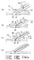
まず、本発明の基本的な実施例を図1から図4によって説明する。図1において、接合作業は(A)から(D)の順序で進行する。
図1(A)において、板状の2つの部材10、20を架台50に載せて突き合わせている。2つの部材10、20は隙間ができるだけ小さくなるように突き合わせている。部材10には部材20との突き合わせ部に沿って突出片15があり、これに部材20が載っている。部材10、20は突き合わせ部の上面側には凸部12、22を設けている。この状態で部材10、20は拘束具(図示せず)で架台50に固定されている。部材10、20はアルミニウム合金製である。突き合わせ部を接合線という。
【0010】
上記のように拘束の後、2つの部材10、20の突き合わせ面を上方から切削具60で切削する。これによって2つの部材10,20との突き合わせ面に一定の幅の隙間すなわち溝40ができる。前記溝40の切削幅は部材10、20を突き合わせた際に生じていた隙間よりも大きい。溝40の下面(切削部の底面)は突出片15の上面までである。(図1(A))
【0011】
2つの凸部12、22の幅を検出器で検出し、その中心に切削具60の中心を位置させて、切削を行う。切削具60の挿入深さは、凸部12、22の上面の位置を検出して一定にする。切削はドライ切削で行う。切り子は圧縮空気で吹き飛ばすか、集塵機で吸引する。切削具60として図1ではエンドミルを示すが、丸鋸でもよい。
【0012】
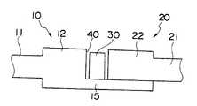
次に、切削によって生じた溝40に補填材30を配置する。補填材30の高さ寸法は、補填材30の上面が凸部12、22の上面よりも下方に位置する大きさである。補填材30の上面は、凸部12、22を除く部材10、20の板11、21の上面の延長線よりも上方に位置している。補填材30の幅は溝40の幅にできるだけ近く、挿入しやすい大きさが望ましい。溝40の幅と補填材30の幅との差は1mm未満である。(図1(B)、図2)
【0013】
次に、溝40の近傍の凸部12、22の上面を上方から押さえて、凸部12、22の角部を溝40側に曲げる。これによって、補填材30は下方に向けて押さえられ、部材10、20に固定される。この固定は回転工具80によって摩擦攪拌接合する際に、補填材30が移動しないようにするためである。
【0014】
このかしめ作業は、溝40に沿ってローラ70を走行させることによって行う。ローラ70の先端は台形状である。ローラ70の幅の中心が2つの部材10、20の中心(溝40の中心)に位置する。ローラ70の台形状の斜面で凸部12、22の角部を押さえる。これによって凸部12、22の角部はかしめられる。2つの凸部12、22の幅を検出器で検出し、その中心にローラ70の中心を位置させて、押さえる。(図1(B)、図3)
【0015】
ローラ70は、空気シリンダ装置75によって凸部12、22に押し付けられ、溝40の内側に向けて凸部12,22を変形させてかしめ作業を行う。シリンダ装置75は、凸部12、22の高さ位置の変化を許容するように伸縮自在である。もし、後述する仮止め溶接のビードがあれば、ローラ70はそれを乗り越える。
【0016】
次に、回転工具80を突き合わせ部に上方から挿入し、部材10、20および補填材30の3者を摩擦攪拌接合する。回転工具80は接合線に沿って移動する。回転工具80の小径部82の先端は突出片15に達する。すなわち、小径部82の先端は、溝40の底部まで達した状態で接合を行なう。小径部82の径は溝40の幅よりも大きい。2つの凸部12、22の幅を検出器で検出し、溝40の中心に回転工具80の中心軸を位置させて、摩擦攪拌接合を行う。回転工具80の挿入深さは、凸部12、22の上面の位置を検出して一定にする。(図1(C)、(D)、図4)
摩擦攪拌接合した後、必要により、板11、21の上面よりも上方の凸部12、22および接合部を切削し、平滑にする。
【0017】
各部の大きさの一例を説明する。溝40の幅:3mm、溝40の深さ6mm、板11、21の厚さ:4mm、凸部12、22の高さ(板11、21の部分を除く):2mm、凸部12、22の幅:8mm、補填材30の幅:2.5mm、補填材30の高さ:5.5mm、回転工具80の大径部81の径:15mm、小径部82の径:6mm、回転工具80の傾斜角:4°。摩擦攪拌接合時において、大径部81と小径部82との境(正確には大径部81の最下端)は板11、21の上面と補填材30の上面との間に位置する。
【0018】
これによれば2つの部材を突き合わせた際に接合線に沿って1mm以上の隙間があっても、切削によって所定の幅を有する溝に拡大し、次に、補填材30を配置して隙間を1mm未満にし、次に、摩擦攪拌接合しているので、良好な接合ができるものである。板11、21の厚さに相当する部分の溝40と補填材30との隙間は、凸部12、22および補填材30の上部の金属を原資として埋められる。
かしめのみでは補填材30の固定が十分でない場合は、アーク溶接によって補填材30を凸部12、22に間欠的に仮止め溶接する。
【0019】
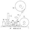
図5の実施例を説明する。61は切削具60としての丸鋸である。丸鋸61の後方において、切り子を吸引口65で吸引している。また、ゴム製の排除板66で切り子が後方に行かないようにしている。補填材30はドラム90に巻かれている。補填材30はドラム90からガイドローラ93b、93c、93dによって滑らかに円弧状に曲げられ、筒状のガイド95を経由して溝40に挿入される。ドラム90とローラ70の間にはこのようなローラ93b、93c、93d、ガイド95が適宜設置されている。補填材30が溝40に入ると、ローラ70で固定され、回転工具80で摩擦攪拌接合される。これら機器は1つの台車に設置している。ドラム90は台車の走行に伴って、補填材30を繰り出す。
凸部12、22をかしめて補填材30を固定するに際し、最初は補填材30の端部を溶接で凸部12、22に固定するとよい。
【0020】
上記実施例では補填材30を溝40に入れるローラ70と凸部12、22をかしめるローラ70とが同一であるが、両者をそれぞれのローラで行うようにすることができる。補填材30を溝40に挿入するローラは補填材30の上面を押さえるようにする。
【0021】
また、ローラ70で凸部12、22をかしめて補填材30を固定しているが、補填材30の上面をローラ70で押さえて固定するようにしてもよい。この場合、補填材30の上面を凸部12、22の上面よりも突出させるとよい。台車の走行方向に複数のローラ70を設けて、強固に固定するとよいと考えられる。
【0022】
また、溝40への補填材30の固定は、ローラ70で凸部12、22を押さえて行っているが、間欠的に2つの凸部12、22を叩いて行うことができる。叩く部材はのみのように小断面積にする。また、溝40を切削した際の切り子は圧縮空気を吹き付けて排除することができる。
【0023】
摩擦攪拌接合し、平滑にした後、ヘアーライン加工仕上げを行う場合は、補填材30の材質は母材の部材10、20と同一材質を用いるとよい。母材と異なる材質の補填材を用い、溶接部を塗装しないでヘアーライン加工仕上げを行う場合は、接合部が変色して見え易く、身栄えが悪い。しかし、母材と同一材質の補填材を用いれば、変色が少なく、見栄えが悪くない。
【0024】
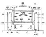
図6から図9の実施例を説明する。これは軌条車両例えば鉄道車両の車体の製作に適用したものである。軌条車両の車体は、床になる台枠110、側面を構成する側構体120、120、屋根になる屋根構体130等からなる。先ず、一対の側構体120、120の上部に屋根構体130を載せ、接合し、一体にする。次に、これを台枠に載せ、接合し一体にする。ここでは台枠と側構体との摩擦攪拌接合装置を説明する。
【0025】
台枠110は架台210に載せて固定してある。台枠110に側構体120、120を載せている。側構体120、120の上部には屋根構体130が接合されている。側構体120、120と屋根構体130とを接合した後、台枠110に載せている。
【0026】
側構体120の上部は側方から支持装置230で支持している。支持装置230は車体の両側面に沿って設置した枠220に設置している。支持装置230は水平方向に伸縮自在である。車体の内側には支持装置240が配置され、一対の側構体120、120の間隔や垂直度を所定にしている。支持装置240は側構体120、120の上部と上部との間、下部と下部との間、および上部と下部との間にある。支持装置240は2つの側構体120、120の間隔を大きくする支え棒や、間隔を小さくするチエン等である。いずれもターンバックルを備え、間隔を変更できる。チエンは窓などにかけ、引っ張っている。また、側構体120の下端は車外側から車内側に向けて押さえている。
【0027】
車体の両側面には接合装置300、300がある。接合装置300の上下はレール301、302で支持され、車体に沿って直線状に走行する。接合装置300は台車310に設置している。接合装置300は下部のレール302にローラを介して載っており、またレールの左右の面に接するローラがある。また、接合装置300の上部には上部のレール301の左右の面に接するローラがある。レール302は枠220の上部に設置している。
【0028】
接合装置300は前記実施例の機器である。接合装置300は台車310の昇降台320に設置している。昇降台320は台車310の四角形の枠の左右の柱にガイドされて昇降する。昇降台320の上部には上下方向に回転する座330がある。この回転座330の上面に水平方向に移動する水平移動座340がある。水平移動座340の上面には上下動する上下動座350がある。この上下動座350、350に前記実施例の機器を設置している。すなわち、一方の上下動座350に丸鋸61、その駆動装置、吸引口65、排除板66、センサ等を設置している。他方の上下動座350にローラ70、93b、93c、93d、ガイド95、回転工具80、その駆動装置、センサ等を設置している。台車310の上部にドラム90を設置している。
【0029】
それぞれの前記センサは凸部の幅、位置を検出し、水平移動座340、上下動座350を移動させ、丸鋸61、回転工具80の位置、深さを制御する。水平移動座340は車体に対する距離を変えるものである。
回転座330は、接合すべき部分の車体の形状が垂直面に対して傾斜している場合に用いる。
【0030】
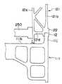
図9において、台枠110、側構体120は複数の中空形材をそれぞれ接合したものである。側構体120の下端の中空形材121のそれぞれの面板121b、121cを台枠110の端部の中空形材111に突き合わせている。中空形材111は側梁と呼ばれ、高さや板厚は他の中空形材112よりも大きい。
【0031】
車内側の面板121cは中空形材111の上面の面板111bに載っている。両者は実質的に直交している。この突き合わせ部を車内側からアーク溶接で隅肉溶接している。
車外側の面板121bは中空形材111の上部の角部の凹部111dに突き合わせられ、凹部111dに重なっている。この突き合わせ部を車外側から摩擦攪拌接合する。
【0032】
凹部111dは中空形材111の上面の面板111bと車外側の垂直な板111cとの接続部にある。凹部111dは上方および車外側にそれぞれ開口している。凹部111dには上方に突出する突出片111fがある。突出片111fは面板121bの裏面に重なる。
【0033】
丸鋸61の厚さの中心および回転工具80の軸心の延長線は、面板111bの板厚の範囲内にある。これによって切削および摩擦攪拌接合時の荷重を面板111bで支え、接合部の変形を防止し、良好な接合を可能にする。
【0034】
台枠110の中空形材111、112の上面の面板111b、112bは実質的に同一面にある。面板121bの下端の車外側、および接続板111cの上端の車外側にはそれぞれ凸部12、22がある。
左側の側構体120と台枠110との接合部の構成は以上の構成と同一である。
【0035】
接合手順を説明する。台枠110を架台210に載せ、これに側構体120、120を載せ、支持装置230、240で側構体120を所定位置に固定する。台枠110と側構体120、120とを車内側、車外側から間欠的に仮止め溶接する。次に、車内側は面板121cと面板111bとを本格的にアーク溶接する。
【0036】
次に、左右の接合装置300、300を同期して走行させ、同期して接合する。接合装置300の丸鋸61によって接合部に溝40を設け、これに補填材30を配置し、最後に摩擦攪拌接合する。
車体の長手方向の端部から丸鋸61で溝40を作る切削を開始する。所定の長さの溝40を作ると台車310の走行を停止し、ドラム90から補填材30を繰り出して、溝40に挿入する。
【0037】
次に、溝40に挿入した補填材30を凸部12、22に仮止め溶接する。溶接位置は溝40に挿入した補填材30の始端である。次に、ローラ70を溝40側の所定位置に突出させ、台車310の走行を開始させる。切削も再開する。溝40への補填材30の挿入を開始すると共に、ローラ70によって固定を行う。
【0038】
摩擦攪拌接合装置の回転工具80が接合線の始端の位置まで移動すると、台車310の走行を停止させる。回転工具80を回転させながら、接合すべき部分に挿入する。次に、台車310の走行を再開する。
【0039】
左右の接合装置300、300を同期させて摩擦攪拌接合を行っている。つまり、右の接合装置300の回転工具80の軸心の延長線上に実質的に左側の接合装置の回転工具80の軸心がある。両者の間には台枠110の面板111b、112bがある。このため、摩擦攪拌接合時の大きな荷重はこれらによって支持され、台枠110の変形を防止できる。
【0040】
ただし、一般には、回転工具80の軸心は走行方向に対して傾斜している。このため、一方の回転工具の軸心の延長線上には他方の回転工具80が存在しないことが多い。この場合も一方の回転工具80の荷重を他方の回転工具80で支持できないが、近傍を支持している。このため、台枠等の変形を防止して摩擦攪拌接合できる。
【0041】
一方の回転工具80の荷重を他方側で支持する装置として、前記一方の回転工具80の軸心の延長線上をローラで支持し、前記一方の回転工具80に同期して走行させる。ローラが複数からなる場合は接合線に沿って設ける。また、他方の接合部の周辺を支持する支持装置を設置して支持する。前記一方の回転工具80に対して他方側は回転工具80を除く支持装置でもよい。この場合、支持装置は接合部または未接合部を支持する。
【0042】
車体には、通常、キャンバーを設けてる。台枠110にキャンバーを設けていれば、切削の高さ位置、摩擦攪拌接合の高さ位置はキャンバーに従って上下動させる。この場合、切削具としては丸鋸よりもエンドミルが好適である。
【0043】
上記実施例では定常時は凸部12、22のかしめによって補填材を固定しているが、溶接によって所定間隔で固定してもよい。溶接装置は丸鋸61とガイド95との間に設ける。
【0044】
中空型材121の面板121bと中空型材111の面板111cとの接合は、実質的に平行な2つの面板(1つは111c)を接続する接続板111gと面板111cとの接続部111hで行うことができる。接続部111hよりも上方の面板111cは面板121bが重なるように凹んでいる。これによって面板121bの下端は接続部111hよりも下方の面板111cに突き合わせられる。回転工具80の軸心の延長線上に接続板111gが位置する。これによって回転工具80の荷重を支持できる。面板121cの端部は面板111bに溶接する。
【0045】
図10の実施例を説明する。台枠110の端部の中空形材111の車外側には上方に突出する突出片(面板に相当する)111jがある。これに側構体の中空形材121の車外側の面板121bを突き合わせている。突出片111jと面板121bとの突き合わせ部の裏面には内外の面板121b、121cを接続する接続板121dがある。接続板121dは面板121b、121cに実質的に直交している。このため、接続板121dは接合時の回転工具80の軸心の延長線上にある。接続板121dと面板121bとの接続部には、前記実施例と同様に、中空計11の突出片111jを突き合わせる凹部および突出片が形成されている。
【0046】
面板121cと面板111bとを溶接後、支持装置250を面板121cに接するように配置する。支持装置250は車体の長手方向に沿って多数設置する。支持装置250は伸縮自在である。次に、摩擦攪拌接合する。一方の回転工具80の荷重は支持装置250を介して他方の回転工具80側に伝達する。
【0047】
図11の実施例を説明する。中空形材111の上方に2つの突出片111p、111pが突出している。2つの突出片(面板に相当する)111p、111pは接続片111qで接続している。接続片111qは図10の接続片121dと同様に設置している。接続片111qと突出片111p、111pとの接続部には前記実施例と同様に面板121b、121cに重なる凹部および突出片がある。
面板121cと突出片111pを溶接後、支持装置250を配置する。支持装置250は面板121c、突出片111pの両方に接触するのが好ましい。回転工具80の軸心の延長線上に接続板111qを位置させて、摩擦攪拌接合する。
【0048】
なお、この実施例において、突出片111pの長さが短ければ、台枠110が強固であるので、支持装置250を不要にできる。
【0049】
図12から図13の実施例を説明する。これは屋根構体130と側構体120、120との接合装置である。側構体120、120を架台210Bに載せて立て、これに屋根構体130を載せている。これを支持装置250、240Bによって車体の内外から支持している。支持装置240Bは屋根構体130、側構体120を車内側から引っ張ったり押したりする。支持装置250、240Bは前記実施例の支持装置240に相当する。また、側構体120の下端は架台210Bの凹部に入れて位置決めしている。
【0050】
支持装置240Bによって側構体120、120、屋根構体130を所定位置に固定したら、側構体120、120と屋根構体130との車内側の突き合わせ部をアーク溶接する。溶接したらこの左右の溶接部の間に支持装置250を配置する。支持装置250は溶接部の近傍を支持する。支持装置250は支え棒である。
【0051】
次に、前記のように左右の台車310B、310Bを走行させ、接合装置300B、300Bで溝を切削し、補填材を充填し、摩擦攪拌接合する。摩擦攪拌接合時の荷重は、接合部の接続板、支持装置250を介して、他方の接続板、回転工具80に支持される。
【0052】
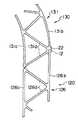
側構体120の上端の中空形材126と屋根構体130の下端の中空形材131との接合部の構成を説明する。中空形材126(131)の2枚の面板126bと面板126c(131b、131c)との間には接続板126d(131d)がトラス状に配置されている。面板131bの端部と面板131cの端部とは傾斜した接続板131dで接続されている。面板126bの端部と面板126cの端部とを接続する接続板はない。このため、面板131c(126b)の端部は面板131b(126c)よりも端部側に突出している。面板131bと2つの接続板131d、131dとの接続部(交点)には、前記実施例と同様に凹部があり、裏面に突出片がある。面板126cと端部の接続板126dとの接続部(交点)には、前記実施例と同様に凹部があり、裏面に突出片がある。面板131bの凹部および突出片に中空形材126の面板126bが重なっている。面板126cの凹部および突出片に中空形材131の面板131cが重なっている。車外側の面板126b、131bの突き合わせ部には凸部12、22がある。丸鋸61の厚さの中心、回転工具80の軸心の延長線は、2つの接続板131d、131dの交点にある。
【0053】
摩擦攪拌接合時の荷重は2つの接続板131d、131dを介して面板131cに伝達される。そして支持装置250を介して他方の側構体120に伝達する。
【0054】
図14の実施例を説明する。2つの側構体120、120の間に架台210Bに設置した支持装置250Bがあり、支持装置260を設置している。車内側を溶接した後、支持装置260で支持する。ところで、支持装置260に前記実施例のローラや回転工具を設置することができる。支持装置260がローラや回転工具を備えた場合は車外側の回転工具80に同期して移動する。
【0055】
図15の実施例を説明する。2つの部材10、20を前記のように突き合わせた後、接合線に沿ってアーク溶接を行う。前記アーク溶接は、接合線に沿って連続して行う。特に、隙間がある個所を溶接し、隙間をできるだけ埋める。(図15(A)、(B))
【0056】
次に、回転工具80で摩擦攪拌接合を行う。この場合、盛り上がった溶接ビードBを凸部12、22に見立てて行う。すなわち、盛り上がった溶接ビードB内に回転工具80の大径部81の最下端を位置させて摩擦攪拌接合を行う。なお、部材10、20に凸部12、22を設けたものを溶接してもよい。(図15(C)、(D))
【0057】
前記溶接は隙間の補填材として行うものである。本来は隙間がないように突き合わせるので、その突き合わせ部はI型開先である。このため、隙間の下部に溶接ビード(補填材)が溶け込まないことがある。しかし、盛り上がった溶接ビードBや凸部12、22が補填材となる。この溶接の強度は摩擦攪拌接合されていない部分の溶接ビードBが摩擦攪拌の力で剥離しない程度でよい。
2つの部材を突き合わせ、切削を行い、次に2つの部材の溝が少なくなるか、なくするように移動させて突き合わせ、この状態で摩擦攪拌接合することができる。
【0058】
本発明の技術的範囲は、特許請求の範囲の各請求項の記載の文言あるいは課題を解決するための手段の項に記載の文言に限定されず、当業者がそれから容易に置き換えられる範囲にもおよぶものである。
【0059】
【発明の効果】
本発明によれば、2つの部材の突き合わせ部の隙間に、隙間を埋める部材を配置し、その後、摩擦攪拌接合しているので、良好な接合ができるものである。
また、2つの部材の突き合わせ部を切削し、両者を近接させてから摩擦攪拌接合すれば、良好な接合ができるものである。
【0060】
車体の台枠と側構体との摩擦攪拌接合は、台枠の面板を支持手段にするか2つの側構体の間に支持装置を配置して行っているので、容易に行えるものである。
側構体と屋根構体との摩擦攪拌接合は、2つの側構体の間に支持装置を配置して行っているので、容易に行えるものである。
【図面の簡単な説明】
【図1】 本発明の一実施例の接合の工程図。
【図2】 図1のII−II断面図。
【図3】 図1のIII−III断面図。
【図4】 図1のIV−IV断面図。
【図5】 本発明の他の実施例の接合装置の構成図。
【図6】 本発明の他の実施例の接合装置の正面図。
【図7】 図6のVII−VII断面図。
【図8】 図7のVIII−VIII断面図。
【図9】 図6の台枠と側構体との接合部の縦断面図。
【図10】 本発明の他の実施例の図9相当図。
【図11】 本発明の他の実施例の図9相当図。
【図12】 本発明の他の実施例の接合装置の正面図。
【図13】 図12の側構体と屋根構体との接合部の縦断面図。
【図14】 本発明の他の実施例の接合装置の正面図。
【図15】 本発明の他の実施例の接合の工程図。
【符号の説明】
10、20:部材、11、21:板、12、22:凸部、30:補填材、40:溝、60:切削具、70:ローラ、80:回転工具、90:ドラム、110:台枠、111、112:中空形材、120:側構体、121、126:中空形材、130:屋根構体、131:中空形材、250:支持装置、300:接合装置、310:台車、250B:支持装置、300B:接合装置、310B:台車。[0001]
BACKGROUND OF THE INVENTION
The present invention relates to a friction stir welding method. In particular, the present invention relates to a joining method suitable for manufacturing a vehicle traveling on a rail, for example, a vehicle body of a railway vehicle.
[0002]
[Prior art]
The friction stir welding method is a method in which a round bar (referred to as a rotary tool) inserted into a joint is moved along a joining line while rotating, the joint is heated and softened, plastically flowed, and solid-phase joining is performed. A rotary tool consists of a large diameter part and a small diameter part. The small diameter portion is inserted into the member to be joined, and the end surface of the large diameter portion is brought into contact with the member. A screw is provided in the small diameter portion. A convex portion is provided at the abutting portion of the two members to be joined, and a rotary tool is inserted from the convex portion side so that the gap between the two members is filled with the metal of the convex portion. The large diameter part of the rotary tool is placed in the convex part. Friction stir welding of hollow shape members is performed by friction stir welding of hollow shape members using a connecting plate connecting two face plates as a support plate. These are disclosed in Japanese Patent No. 3070735 (USP 6050474) and Japanese Patent Application Laid-Open No. 2000-334581 (EP1055478A1).
[0003]
Moreover, in FIG. 14 of Unexamined-Japanese-Patent No. 2000-233285, a filler is arrange | positioned in the clearance gap between two members, and friction stir welding is carried out. Further, in Japanese Patent Laid-Open No. 2000-167777 (EP 09931414A2), when friction stir welding is performed on a first member having a convex portion and a second member not having a convex portion, the second member side is intermittently exposed to the meat. Welding is performed, followed by friction stir welding.
[0004]
[Problems to be solved by the invention]
If there is a gap between the two members to be joined, friction stir welding cannot be performed. For this reason, a convex part is provided on the insertion side of the rotary tool, and the gap is filled with the metal of the convex part. However, in reality, for example, when the gap is 1 mm or more, it is difficult to perform good bonding. Although it is conceivable to increase the diameter of the rotary tool when the gap becomes large, inconvenience is likely to occur.
[0005]
Body of the railway vehicle such as a railway vehicle includes a side structure constituting avehicle body side, consisting of a roof structure, underframe or the like constituting the bed. The vehicle body is manufactured by first joining a plurality of extruded shapes to manufacture a side structure, a roof structure, and a frame. Next, these are joined to form a vehicle body. Since the side structure, the roof structure, and the frame are about 20 m long and about 3 m wide, the manufacturing error is large. For this reason, the clearance gap of a junction part becomes 1 mm or more easily.
[0006]
An object of the present invention is to enable good bonding even when the gap is large.
[0007]
[Means for Solving the Problems]
The purpose isto abut theabutting surfaces of the two members, cut the abutting surfaces of the two members along the joining line to form a groove, insert a filling material into the groove, and frictionstir tothe bottom of the grooveThis can be achieved by inserting the tip of a welding rotary tool and friction stir welding the two members and the filling material along the joining line.
[0008]
Further, a pedestal for placing the butted surfaces of the two members in a butted state, a cutting device for cutting the butted surfaces of the two members along a joining line of the two members, and a filling material for the groove generated by the cutting Can be achieved by a friction stir welding apparatus comprising: a filling material inserting device for inserting the tip, and a rotary tool for inserting the tip to the bottom of the groove and friction stir welding the two members and the filling material.
[0009]
DETAILED DESCRIPTION OF THE INVENTION
First, a basic embodiment of the present invention will be described with reference to FIGS. In FIG. 1, the joining operation proceeds in the order of (A) to (D).
In FIG. 1 (A), two plate-
[0010]
After restraining as described above, the butted surfaces of the two
[0011]
The width of the two
[0012]
Next, the filling
[0013]
Next, the top surfaces of the
[0014]
This caulking work is performed by running the
[0015]
The
[0016]
Next, the
After the friction stir welding, if necessary, to cut the
[0017]
An example of the size of each part will be described. The width of thegroove 40: 3 mm, the depth of the
[0018]
According to this, even when there is a gap of 1 mm or more along the joining line when the two members are butted together, thegroove is expanded toa groove having a predeterminedwidth by cutting, and then the filling
If fixing of the filling
[0019]
The embodiment of FIG. 5 will be described. 61 is a circular saw as the cutting tool 60. At the rear of the
When the
[0020]
In the above embodiment, the
[0021]
In addition, although the
[0022]
Further,the fixing
[0023]
When the hairline processing finish is performed after the friction stir welding and smoothing, the material of the filling
[0024]
The embodiment of FIGS. 6 to 9 will be described. This is applied to the production of a rail vehicle, for example, the body of a railway vehicle. The vehicle body of the rail vehicle includes a
[0025]
The
[0026]
The upper part of the
[0027]
There are joining
[0028]
The joining
[0029]
Each of the sensors detects the width and position of the convex portion,moves the horizontalmoving
The
[0030]
In FIG. 9, a
[0031]
The
The
[0032]
The concave portion 111d is located at a connection portion between the face plate 111b on the upper surface of the hollow shape member 111 and the vertical plate 111c on the outside of the vehicle. The concave portion 111d opens upward and outward of the vehicle. The recess 111d has a protruding piece 111f protruding upward. The protruding piece 111f overlaps the back surface of the
[0033]
The center of the thickness of the
[0034]
The face plates 111b and 112b on the upper surfaces of the
The configuration of the joint between the
[0035]
A joining procedure will be described. The
[0036]
Next, the right and left joining
Cutting to make the
[0037]
Next, the filling
[0038]
When the
[0039]
Friction stir welding is performed by synchronizing the right and left joining
[0040]
However, generally, the axis of the
[0041]
As a device for supporting the load of one
[0042]
Thebody, usually,is provided with acamber. If the camber is provided in the
[0043]
In the above embodiment, the filling material is fixed by caulking the
[0044]
The
[0045]
The embodiment of FIG. 10 will be described. Aprojecting piece (corresponding to a face plate) 111jprojecting upward is provided on the outer side of the hollow member 111 at the end of the
[0046]
After welding the
[0047]
The embodiment of FIG. 11 will be described. Two protruding pieces111p and 111p protrude above the hollow shape 111. Two protruding pieces (corresponding to face plates) 111p and 111p are connected by a connecting piece 111q. The connection piece 111q is installed in the same manner asthe
After welding the
[0048]
In this embodiment, if the length of the protruding piece 111p is short, the
[0049]
The embodiment of FIGS. 12 to 13 will be described. This is a joining device for the
[0050]
When the
[0051]
Next, the left and
[0052]
A configuration of a joint portion between the
[0053]
The load at the time of friction stir welding is transmitted to the
[0054]
The embodiment of FIG. 14 will be described. There is a
[0055]
The embodiment of FIG. 15 will be described. After the two
[0056]
Next, friction stir welding is performed with the
[0057]
The welding is performed as a gap filling material. Originally, the abutting portion is an I-shaped groove because the abutting portion is not a gap. For this reason, the weld bead (filling material) may notmelt into the lower part of the gap. However, the raised weld bead B and the
The two members can be butted and cut, and then moved so that the grooves of the two members are reduced or eliminated, and the friction stir welding can be performed in this state.
[0058]
The technical scope of the present invention is not limited to the language described in each claim of the claims or the language described in the section of the means for solving the problem, and includes a range that can be easily replaced by those skilled in the art. It extends.
[0059]
【The invention's effect】
According to the present invention, since the member that fills the gap is disposed in the gap between the butted portions of the two members and then friction stir welding is performed, good bonding can be achieved.
Further, if the abutting portions of the two members are cut and the two members are brought close to each other and then friction stir welding is performed, good bonding can be achieved.
[0060]
Friction stir welding between the frame of the vehicle body and the side structure can be easily performed because the face plate of the frame is used as a support means or a support device is disposed between the two side structures.
The friction stir welding between the side structure and the roof structure is easily performed because the support device is disposed between the two side structures.
[Brief description of the drawings]
FIG. 1 is a process diagram of bonding according to an embodiment of the present invention.
FIG. 2 is a cross-sectional view taken along the line II-II in FIG.
3 is a sectional view taken along line III-III in FIG.
4 is a cross-sectional view taken along the line IV-IV in FIG.
FIG. 5 is a configuration diagram of a bonding apparatus according to another embodiment of the present invention.
FIG. 6 is a front view of a joining apparatus according to another embodiment of the present invention.
7 is a sectional view taken along line VII-VII in FIG.
8 is a cross-sectional view taken along the line VIII-VIII in FIG.
9 is a longitudinal sectional view of a joint portion between the underframe and the side structure in FIG. 6;
FIG. 10 is a view corresponding to FIG. 9 of another embodiment of the present invention.
FIG. 11 is a view corresponding to FIG. 9 of another embodiment of the present invention.
FIG. 12 is a front view of a joining apparatus according to another embodiment of the present invention.
13 is a longitudinal sectional view of a joint portion between the side structure and the roof structure in FIG. 12;
FIG. 14 is a front view of a joining apparatus according to another embodiment of the present invention.
FIG. 15 is a process chart of bonding according to another embodiment of the present invention.
[Explanation of symbols]
10, 20: member, 11, 21: plate, 12, 22: convex portion, 30: filling material, 40:groove , 60: cutting tool, 70: roller, 80: rotating tool, 90: drum, 110: underframe 111, 112: Hollow profile, 120: Side structure, 121, 126: Hollow profile, 130: Roof structure, 131: Hollow profile, 250: Support device, 300: Joining device, 310: Cart, 250B: Support Device, 300B: Joining device, 310B: Cart.
Claims (16)
Translated fromJapanese前記2つの部材の突き合わせ面を接合線に沿って切削して溝を形成し、
前記溝に補填材を挿入し、
前記溝の底部まで摩擦撹拌接合用回転工具の先端を挿入し、前記接合線に沿って前記2つの部材および前記補填材を摩擦攪拌接合すること、
を特徴とする摩擦攪拌接合方法。Butt the butting surfaces of the two members
Cuttingthe butted surfaces of the two members along the joining lineto form a groove ;
Insert a filling material into thegroove ,
Inserting the tip of the rotary tool for friction stir welding to the bottom of the groove, and friction stir welding thetwo members and the filling material along the joining line;
A friction stir welding method characterized by the above.
前記溝に挿入した補填材を溝の周囲の前記部材に固定し、
前記摩擦攪拌接合すること、
を特徴とする摩擦攪拌接合方法。In the friction stir welding method according to claim 1,
Fixing the filling material inserted into thegroove to the member around thegroove ;
The friction stir welding,
A friction stir welding method characterized by the above.
前記切削を行う装置、前記補填材の挿入を行う装置、前記摩擦攪拌接合を行う装置、および前記補填材を巻いたドラムを台車に設置しており、
1つの接合線に沿って、前記台車を走行させて、前記切削を行いつつ、前記台車の走行に伴って前記ドラムに巻いた前記補填材を繰り出して前記溝に挿入し、前記前記摩擦攪拌接合を行うこと、
を特徴とする摩擦攪拌接合方法。In the friction stir welding method according to claim 1,
A device that performs the cutting, a device that inserts thefilling material, a device that performs the friction stir welding, and a drum wound with the filling material are installed in a carriage,
The carriage is runalong one joining line, the cutting is performed, the filling material wound around the drum is fed out and inserted into thegroove as the carriage runs, and the friction stir welding is performed. To do the
A friction stir welding method characterized by the above.
前記2つの部材の突き合わせ面を前記2つの部材の接合線に沿って切削する切削装置と、
前記切削によって生じた溝に補填材を挿入する補填材挿入装置と、
先端を前記溝の底部まで挿入し、前記2つの部材および前記補填材を摩擦攪拌接合する回転工具と、
からなる摩擦攪拌接合装置。Apedestal that is placed withthe butted surfaces of the two membersbutted;
A cutting device that cuts the butted surfaces of the two members along a joining line of the two members;
A filling material insertion device for inserting a filling material into the groove produced by the cutting;
A rotary tool that inserts the tip to the bottom of the groove and friction stir welds the two members and the filling material;
A friction stir weldingapparatus comprising:
前記切削装置、前記補填材挿入装置および前記回転工具は、前記架台に対して移動可能な台車に設置されており、前記台車は架台に載せられた2つの部材の接合線に沿って移動可能に設置されていること、を特徴とする摩擦攪拌接合装置。The friction stir weldingapparatus according to claim 13,
Thecutting device, the filling material insertion device, and the rotary tool areinstalled on a carriagemovable with respect to the gantry,and the trolley is movable along a joining line of two members mounted on the gantry. A friction stir weldingapparatus characterizedby being installed .
前記台車は、前記補填材を巻いたドラムを備えており、
前記ドラムは、前記台車の移動に伴って前記補填材を繰り出す機能を備えていること、
を特徴とする摩擦攪拌接合装置。The friction stir weldingapparatus according to claim14 ,
The carriage includes a drum around which the filling material is wound,
The drum has a function of paying out the filling material as the carriage moves;
A friction stir weldingapparatus characterized by the above.
前記台車は、前記ドラムの補填材を前記溝に挿入する複数のガイドローラを備えていること、
を特徴とする摩擦攪拌接合装置。The friction stir welding apparatus according to claim 15,
The carriage includes a plurality of guide rollers for inserting the drum filling material into the groove ;
A friction stir weldingapparatus characterized by the above.
Priority Applications (40)
| Application Number | Priority Date | Filing Date | Title |
|---|---|---|---|
| JP2001009035AJP3761786B2 (en) | 2001-01-17 | 2001-01-17 | Friction stir welding method and apparatus |
| TW090112956ATW501963B (en) | 2001-01-17 | 2001-05-29 | Friction stir welding method, and method for manufacturing car body |
| CNA2006100877381ACN1911586A (en) | 2001-01-17 | 2001-07-25 | Friction stir welding method, and method for manufacturing car body |
| EP07008267AEP1808259B1 (en) | 2001-01-17 | 2001-07-25 | Friction stir welding method, and method for manufacturing car body |
| DE60138085TDE60138085D1 (en) | 2001-01-17 | 2001-07-25 | Rotary friction welding method and method for producing a body composite part |
| DE60142317TDE60142317D1 (en) | 2001-01-17 | 2001-07-25 | Rotary friction welding process for producing a body composite part |
| AT07008266TATE464148T1 (en) | 2001-01-17 | 2001-07-25 | ROTATING FRICTION WELDING METHOD AND METHOD FOR PRODUCING A COMPOSITE BODY PART |
| CNA2006100877377ACN101096063A (en) | 2001-01-17 | 2001-07-25 | Friction stir joining method and car body manufacturing method |
| AT07008268TATE469722T1 (en) | 2001-01-17 | 2001-07-25 | ROTATING FRICTION WELDING PROCESS FOR PRODUCING A COMPOSITE BODY PART |
| ES07008266TES2345222T3 (en) | 2001-01-17 | 2001-07-25 | WELDING METHOD BY FRICTION-ROTATION, AND METHOD FOR MANUFACTURING BODIES. |
| EP07008268AEP1808260B1 (en) | 2001-01-17 | 2001-07-25 | Method for manufacturing car body using friction stir welding. |
| EP07008265AEP1808257A3 (en) | 2001-01-17 | 2001-07-25 | Friction stir welded car body |
| CNB2006100877362ACN100479966C (en) | 2001-01-17 | 2001-07-25 | Method for manufacturing car body |
| AT01306355TATE426480T1 (en) | 2001-01-17 | 2001-07-25 | ROTATING FRICTION WELDING METHOD AND METHOD FOR PRODUCING A COMPOSITE BODY PART |
| EP07008266AEP1808258B1 (en) | 2001-01-17 | 2001-07-25 | Friction stir welding method, and method for manufacturing car body |
| CNB2006100877396ACN100479967C (en) | 2001-01-17 | 2001-07-25 | Method for manufacturing car body |
| CNB2006100877409ACN100488695C (en) | 2001-01-17 | 2001-07-25 | Method for manufacturing car body |
| CNB2006100877413ACN100488696C (en) | 2001-01-17 | 2001-07-25 | Method for manufacturing car body |
| ES07008267TES2339600T3 (en) | 2001-01-17 | 2001-07-25 | WELDING METHOD BY FRICTION-AGITATION AND METHOD TO MANUFACTURE A BODYWORK. |
| ES01306355TES2320627T3 (en) | 2001-01-17 | 2001-07-25 | FRICTION WELDING METHOD WITH AGITATION, AND METHOD FOR MANUFACTURING BODIES. |
| CNA2006100877428ACN1911587A (en) | 2001-01-17 | 2001-07-25 | Friction stir welding method, and method for manufacturing car body |
| DE60141723TDE60141723D1 (en) | 2001-01-17 | 2001-07-25 | Rotary friction welding method and method for producing a body composite part |
| CNB011243961ACN1176777C (en) | 2001-01-17 | 2001-07-25 | Friction stir welding method and method for manufacturing vehicle body |
| AT07008267TATE462527T1 (en) | 2001-01-17 | 2001-07-25 | ROTATING FRICTION WELDING METHOD AND METHOD FOR PRODUCING A COMPOSITE BODY PART |
| DE60141865TDE60141865D1 (en) | 2001-01-17 | 2001-07-25 | Rotary friction welding method and method for producing a body composite part |
| AT08014828TATE515357T1 (en) | 2001-01-17 | 2001-07-25 | ROTATING FRICTION WELDING PROCESS FOR PRODUCING A COMPOSITE BODY PART |
| CNB2004100385405ACN1301175C (en) | 2001-01-17 | 2001-07-25 | Friction stir joining method and car body manufacturing method |
| EP08014828AEP1987909B1 (en) | 2001-01-17 | 2001-07-25 | Friction stir welding method, and method for manufacturing car body |
| EP01306355AEP1224998B1 (en) | 2001-01-17 | 2001-07-25 | Friction stir welding method, and method for manufacturing car body |
| US09/915,354US6530513B2 (en) | 2001-01-17 | 2001-07-27 | Friction stir welding method, and method for manufacturing car body |
| KR10-2001-0045910AKR100515313B1 (en) | 2001-01-17 | 2001-07-30 | Friction stir joining method and method of manufacturing car body |
| AU57706/01AAU780657B2 (en) | 2001-01-17 | 2001-07-30 | Friction stir welding method, and method for manufacturing car body |
| US10/084,420US6705508B2 (en) | 2001-01-17 | 2002-02-28 | Friction stir welding method, and method for manufacturing car body |
| US10/084,416US6659330B2 (en) | 2001-01-17 | 2002-02-28 | Friction stir welding method, and method for manufacturing car body |
| US10/084,417US6984455B2 (en) | 2001-01-17 | 2002-02-28 | Friction stir welding method, and method for manufacturing car body |
| KR10-2003-0011606AKR100515312B1 (en) | 2001-01-17 | 2003-02-25 | Method of manufacturing car body |
| KR10-2003-0011607AKR100514772B1 (en) | 2001-01-17 | 2003-02-25 | Car body |
| KR10-2003-0011608AKR100514769B1 (en) | 2001-01-17 | 2003-02-25 | Friction stir joining method |
| KR10-2003-0011605AKR100514770B1 (en) | 2001-01-17 | 2003-02-25 | Friction stir joining method and method of manufacturing car body |
| US10/846,503US20040211819A1 (en) | 2001-01-17 | 2004-05-17 | Friction stir welding method, and method for manufacturing car body |
Applications Claiming Priority (1)
| Application Number | Priority Date | Filing Date | Title |
|---|---|---|---|
| JP2001009035AJP3761786B2 (en) | 2001-01-17 | 2001-01-17 | Friction stir welding method and apparatus |
Related Child Applications (4)
| Application Number | Title | Priority Date | Filing Date |
|---|---|---|---|
| JP2002265697ADivisionJP4633999B2 (en) | 2002-09-11 | 2002-09-11 | How to make a car body |
| JP2005141256ADivisionJP4299266B2 (en) | 2005-05-13 | 2005-05-13 | Body manufacturing method and body manufacturing apparatus by friction stir welding method |
| JP2005256270ADivisionJP4291311B2 (en) | 2005-09-05 | 2005-09-05 | Friction stir welding method |
| JP2005256271ADivisionJP2005342790A (en) | 2005-09-05 | 2005-09-05 | Friction stir welding method |
Publications (3)
| Publication Number | Publication Date |
|---|---|
| JP2002210571A JP2002210571A (en) | 2002-07-30 |
| JP2002210571A5 JP2002210571A5 (en) | 2005-07-28 |
| JP3761786B2true JP3761786B2 (en) | 2006-03-29 |
Family
ID=18876582
Family Applications (1)
| Application Number | Title | Priority Date | Filing Date |
|---|---|---|---|
| JP2001009035AExpired - LifetimeJP3761786B2 (en) | 2001-01-17 | 2001-01-17 | Friction stir welding method and apparatus |
Country Status (10)
| Country | Link |
|---|---|
| US (5) | US6530513B2 (en) |
| EP (6) | EP1987909B1 (en) |
| JP (1) | JP3761786B2 (en) |
| KR (5) | KR100515313B1 (en) |
| CN (9) | CN101096063A (en) |
| AT (5) | ATE469722T1 (en) |
| AU (1) | AU780657B2 (en) |
| DE (4) | DE60141865D1 (en) |
| ES (3) | ES2320627T3 (en) |
| TW (1) | TW501963B (en) |
Families Citing this family (66)
| Publication number | Priority date | Publication date | Assignee | Title |
|---|---|---|---|---|
| CN1165403C (en)* | 1996-03-19 | 2004-09-08 | 株式会社日立制作所 | Components for friction welding |
| DE69712078T2 (en)* | 1997-12-19 | 2002-12-12 | Esab Ab, Goeteborg/Gothenburg | welding device |
| JP3761786B2 (en)* | 2001-01-17 | 2006-03-29 | 株式会社日立製作所 | Friction stir welding method and apparatus |
| AU2005200430B2 (en)* | 2001-01-17 | 2007-01-04 | Hitachi, Ltd. | Friction stir welding method, and method for manufacturing car body |
| US20030111514A1 (en)* | 2001-01-23 | 2003-06-19 | Naoki Miyanagi | Method of friction welding, and frictionally welded structure |
| JP3751215B2 (en)* | 2001-04-16 | 2006-03-01 | 株式会社日立製作所 | Friction stir welding method |
| US20030075584A1 (en)* | 2001-10-04 | 2003-04-24 | Sarik Daniel J. | Method and apparatus for friction stir welding |
| JP3510612B2 (en)* | 2001-11-27 | 2004-03-29 | 川崎重工業株式会社 | Friction stir welding method |
| AU2002352844A1 (en)* | 2001-11-27 | 2003-06-10 | The United States Of America As Represented By The Administrator Of The National Aeronautics And Spa | Thermal stir welding process and apparatus |
| JP3795824B2 (en)* | 2002-04-16 | 2006-07-12 | 株式会社日立製作所 | Friction stir welding method |
| JP4633999B2 (en)* | 2002-09-11 | 2011-02-16 | 株式会社日立製作所 | How to make a car body |
| GB0225518D0 (en)* | 2002-11-01 | 2002-12-11 | Airbus Uk Ltd | Welding method |
| EP1563553B1 (en) | 2002-11-19 | 2007-02-14 | PolyIC GmbH & Co. KG | Organic electronic circuitcomprising a structured, semi-conductive functional layer and a method for producing said component |
| JP2006518671A (en)* | 2003-01-30 | 2006-08-17 | スミス インターナショナル、インコーポレテッド | Out-of-position friction stir welding of high melting point materials |
| JP2004298955A (en)* | 2003-04-01 | 2004-10-28 | Hitachi Ltd | Friction stir welding method |
| JP2004299027A (en)* | 2003-04-01 | 2004-10-28 | Hitachi Ltd | Chip removal method and safety cover |
| DE112005001359A5 (en)* | 2004-07-02 | 2007-05-24 | Siemens Transportation Systems Gmbh & Co. Kg | Method for producing a car body of a rail vehicle |
| US7347351B2 (en)* | 2004-08-18 | 2008-03-25 | The Boeing Company | Apparatus and system for unitized friction stir welded structures and associated method |
| US7078647B2 (en)* | 2004-10-21 | 2006-07-18 | Wisconsin Alumni Research Foundation | Arc-enhanced friction stir welding |
| KR100780019B1 (en)* | 2005-02-01 | 2007-11-27 | 가부시끼가이샤 히다치 세이사꾸쇼 | Friction Stir Welding |
| JP5187712B2 (en)* | 2006-03-09 | 2013-04-24 | 大陽日酸株式会社 | Joining method |
| JP4266024B2 (en)* | 2006-03-28 | 2009-05-20 | 株式会社日立製作所 | Rail vehicle, manufacturing method thereof, and hollow shape material used therefor |
| FR2900082B1 (en)* | 2006-04-20 | 2008-07-18 | Eads Europ Aeronautic Defence | PROCESS FOR FRICTION WELDING MIXING |
| FR2907040B1 (en) | 2006-10-13 | 2009-06-26 | Alstom Transport Sa | METHOD FOR ASSEMBLING A STRUCTURE COMPRISING AN EXTERIOR AND AN INTERIOR CONSISTING OF A PLURALITY OF DOUBLE-SKIN ELEMENTS, SUCH AS A RAILWAY VEHICLE CASE, AND STRUCTURE OBTAINED |
| US20080145495A1 (en)* | 2006-10-30 | 2008-06-19 | Sara Lee Corporation | System and method for conditioning food product |
| US7896216B2 (en)* | 2007-03-30 | 2011-03-01 | Kawasaki Jukogyo Kabushiki Kaisha | Sticking pad, friction stir welding machine and friction stir welding system |
| WO2009022507A1 (en)* | 2007-08-10 | 2009-02-19 | Nippon Light Metal Company, Ltd. | Joining method and method of manufacturing joint structure |
| CN101772395B (en)* | 2007-08-10 | 2013-01-16 | 日本轻金属株式会社 | Joining method and method for manufacturing joined structure |
| KR100922043B1 (en)* | 2007-08-22 | 2009-10-19 | 대한소결금속 주식회사 | Friction Bonding Method of Dissimilar Materials |
| US7762447B2 (en)* | 2008-03-20 | 2010-07-27 | Ut-Battelle, Llc | Multiple pass and multiple layer friction stir welding and material enhancement processes |
| US20090261146A1 (en)* | 2008-03-25 | 2009-10-22 | Hou Gene J | Donor material technology for friction stir welding |
| US8722739B2 (en)* | 2008-10-29 | 2014-05-13 | Novaer Holdings, Inc. | Amino acid salts of prostaglandins |
| DE102008063277A1 (en)* | 2008-12-29 | 2010-07-08 | Bwg Bergwerk- Und Walzwerk-Maschinenbau Gmbh | Method and device for joining metal strips |
| US20110079446A1 (en)* | 2009-10-05 | 2011-04-07 | Baker Hughes Incorporated | Earth-boring tools and components thereof and methods of attaching components of an earth-boring tool |
| KR101548792B1 (en) | 2009-11-02 | 2015-08-31 | 메가스터 테크놀로지스, 엘엘씨 | Out of position friction stir welding of casing and small diameter tubing or pipe |
| CN102085598B (en)* | 2009-12-03 | 2015-10-14 | 鸿富锦精密工业(深圳)有限公司 | Friction stirring connecting method |
| CN102873859B (en)* | 2011-07-15 | 2015-04-08 | 南京肯特复合材料有限公司 | Pressing method and device used in PTFE (Polytetrafluoroethylene) plate welding |
| CN102390017B (en)* | 2011-08-05 | 2014-04-16 | 罗键 | Milling-stirring friction welding combined machining device and near net shaping method of hollow molded cavity |
| US9095927B2 (en)* | 2011-08-19 | 2015-08-04 | Nippon Light Metal Company, Ltd. | Friction stir welding method |
| US9499179B2 (en)* | 2012-02-23 | 2016-11-22 | Kawasaki Jukogyo Kabushiki Kaisha | Railroad vehicle provided with low roof structure |
| JP5970692B2 (en)* | 2012-03-06 | 2016-08-17 | 日本軽金属株式会社 | Method for joining members, method for manufacturing freight transport vehicle, and method for manufacturing freight transport container |
| JP5970212B2 (en)* | 2012-03-16 | 2016-08-17 | 株式会社総合車両製作所 | Method of manufacturing railway vehicle structure and relay member of jig for manufacturing railway vehicle structure |
| US8559587B1 (en)* | 2012-03-21 | 2013-10-15 | Integrated Device Technology, Inc | Fractional-N dividers having divider modulation circuits therein with segmented accumulators |
| KR20180034706A (en)* | 2012-11-30 | 2018-04-04 | 쉴로 인더스트리즈 인코포레이티드 | Method of forming a weld notch in a sheet metal piece |
| JP6084887B2 (en)* | 2013-04-16 | 2017-02-22 | 川崎重工業株式会社 | Friction stir welding apparatus and friction stir welding method |
| EP2862795B1 (en)* | 2013-10-17 | 2017-05-10 | Airbus Operations GmbH | Method of joining panels for an airframe |
| CN106029284B (en)* | 2014-02-17 | 2018-06-29 | 日本轻金属株式会社 | Joint method |
| US20170197274A1 (en)* | 2014-07-10 | 2017-07-13 | Megastir Technologies Llc | Mechanical flow joining of high melting temperature materials |
| US9236873B1 (en) | 2014-12-17 | 2016-01-12 | Integrated Device Technology, Inc. | Fractional divider based phase locked loops with digital noise cancellation |
| CN107708911B (en)* | 2015-05-18 | 2020-01-24 | 株式会社 Ihi | Friction stir welding apparatus and friction stir welding method |
| JP6516605B2 (en)* | 2015-07-16 | 2019-05-22 | 株式会社Uacj | Fixed shoulder type friction stir welding tool and fixed shoulder type friction stir welding method using the same |
| CN105226479B (en)* | 2015-09-28 | 2017-08-25 | 平高集团有限公司 | A kind of preparation method of tubular type conducting rod, hydraulic bulging device and tubular type conducting rod |
| US20170304933A1 (en)* | 2016-04-20 | 2017-10-26 | Brigham Young University | Friction stir additive processing and methods thereof |
| US11305374B2 (en)* | 2016-09-22 | 2022-04-19 | Nemak, S.A.B. De C.V. | Method for the production of a cast engine block for a combustion engine and engine block |
| DE102017204919A1 (en)* | 2017-03-23 | 2018-10-18 | Bayerische Motoren Werke Aktiengesellschaft | Method for producing a workpiece assembly and workpiece assembly |
| US10688592B1 (en)* | 2017-09-05 | 2020-06-23 | United Launch Alliance L.L.C | Friction stir welding of aluminum alloys |
| CN108015405B (en)* | 2017-12-06 | 2020-01-31 | 重庆理工大学 | A friction stir welding device for butt joint of dissimilar metal materials |
| CN108857043A (en)* | 2018-06-26 | 2018-11-23 | 上海航天设备制造总厂有限公司 | A kind of heated filament friction stir welding method |
| CN108857036B (en)* | 2018-07-02 | 2020-06-09 | 南京航空航天大学 | Method and device for rolling friction connection assisted by ultrasonic vibration |
| CN108788442B (en)* | 2018-07-02 | 2020-07-14 | 南京航空航天大学 | A rolling friction connection method of metal pipe fittings |
| US12109647B2 (en)* | 2019-05-17 | 2024-10-08 | Nippon Light Metal Company, Ltd. | Method for producing hollow container |
| JP6698927B1 (en)* | 2019-08-22 | 2020-05-27 | 株式会社フルヤ金属 | Metal-based tubular material manufacturing method and backing jig used therefor |
| CN111545895B (en)* | 2020-06-16 | 2021-08-24 | 东莞市赫泽电子科技有限公司 | Aluminum alloy plate continuous splicing method with good connection effect |
| CN111843173B (en)* | 2020-07-09 | 2025-09-19 | 中车青岛四方机车车辆股份有限公司 | Composite welding method and device for friction stir welding |
| CN117464088B (en)* | 2023-12-27 | 2024-03-22 | 宜宾本色精密工业有限公司 | Automatic V-groove cutting equipment for metal frame of display |
| CN119457397B (en)* | 2024-12-10 | 2025-09-30 | 湖南坤鼎数控科技有限公司 | A laser-assisted friction stir additive welding tool |
Family Cites Families (34)
| Publication number | Priority date | Publication date | Assignee | Title |
|---|---|---|---|---|
| JPS60219220A (en) | 1984-04-17 | 1985-11-01 | Dainippon Ink & Chem Inc | Composition for semi-rigid polyurethane foam |
| EP0672567A1 (en)* | 1994-03-18 | 1995-09-20 | Hitachi, Ltd. | Railway vehicle bodies and methods of manufacturing them |
| US5611479A (en)* | 1996-02-20 | 1997-03-18 | Rockwell International Corporation | Friction stir welding total penetration technique |
| JP3224097B2 (en)* | 1996-03-19 | 2001-10-29 | 株式会社日立製作所 | Friction joining method |
| CN1165403C (en) | 1996-03-19 | 2004-09-08 | 株式会社日立制作所 | Components for friction welding |
| US5769306A (en)* | 1996-05-31 | 1998-06-23 | The Boeing Company | Weld root closure method for friction stir welds |
| JP3268207B2 (en) | 1996-08-06 | 2002-03-25 | 株式会社日立製作所 | Friction welding method |
| JP3333411B2 (en) | 1996-12-18 | 2002-10-15 | 株式会社日立製作所 | Friction stir welding method and friction stir welding device |
| JP3897391B2 (en)* | 1997-03-25 | 2007-03-22 | 昭和電工株式会社 | Friction stir welding method for metal joining members |
| GB9713209D0 (en)* | 1997-06-20 | 1997-08-27 | British Aerospace | Friction welding metal components |
| JP3070735B2 (en) | 1997-07-23 | 2000-07-31 | 株式会社日立製作所 | Friction stir welding method |
| JP3589863B2 (en)* | 1997-07-23 | 2004-11-17 | 株式会社日立製作所 | Structure and friction stir welding method |
| DE69712078T2 (en)* | 1997-12-19 | 2002-12-12 | Esab Ab, Goeteborg/Gothenburg | welding device |
| JP3296417B2 (en)* | 1997-12-24 | 2002-07-02 | 日本軽金属株式会社 | Friction stir welding method |
| JPH11277255A (en)* | 1998-03-26 | 1999-10-12 | Hitachi Ltd | Friction stir welding method and apparatus |
| US5971252A (en)* | 1998-04-30 | 1999-10-26 | The Boeing Company | Friction stir welding process to repair voids in aluminum alloys |
| JP3307330B2 (en)* | 1998-06-01 | 2002-07-24 | 日本軽金属株式会社 | Friction stir welding method and joining structure for thick workpieces |
| JP3420502B2 (en)* | 1998-06-16 | 2003-06-23 | 株式会社日立製作所 | Structure |
| US6168067B1 (en)* | 1998-06-23 | 2001-01-02 | Mcdonnell Douglas Corporation | High strength friction stir welding |
| US6070784A (en)* | 1998-07-08 | 2000-06-06 | The Boeing Company | Contact backup roller approach to FSW process |
| AU733140B2 (en) | 1998-09-29 | 2001-05-10 | Hitachi Limited | A friction stir welding method |
| JP3732688B2 (en) | 1998-09-29 | 2006-01-05 | 株式会社日立製作所 | Friction stir welding method, vehicle body side structure manufacturing method, structure, and vehicle body |
| JP3761735B2 (en) | 1999-02-16 | 2006-03-29 | 株式会社日立製作所 | Friction stir welding method |
| JP3761736B2 (en)* | 1999-02-16 | 2006-03-29 | 株式会社日立製作所 | Friction stir welding method |
| JP3261432B2 (en)* | 1999-05-25 | 2002-03-04 | 川崎重工業株式会社 | Joining apparatus and joining method including pretreatment |
| TW464576B (en)* | 1999-05-28 | 2001-11-21 | Hitachi Ltd | A structure body and a manufacturing method of a structure body |
| JP3481501B2 (en)* | 1999-05-28 | 2003-12-22 | 株式会社日立製作所 | Structure and method of manufacturing the same |
| JP3442692B2 (en)* | 1999-08-12 | 2003-09-02 | 住友軽金属工業株式会社 | Manufacturing method of metal matrix composite |
| JP3538357B2 (en)* | 2000-01-24 | 2004-06-14 | 株式会社日立製作所 | Friction stir welding method |
| JP3761786B2 (en)* | 2001-01-17 | 2006-03-29 | 株式会社日立製作所 | Friction stir welding method and apparatus |
| JP3510612B2 (en)* | 2001-11-27 | 2004-03-29 | 川崎重工業株式会社 | Friction stir welding method |
| JP3795824B2 (en)* | 2002-04-16 | 2006-07-12 | 株式会社日立製作所 | Friction stir welding method |
| JP2004298955A (en)* | 2003-04-01 | 2004-10-28 | Hitachi Ltd | Friction stir welding method |
| US7078647B2 (en)* | 2004-10-21 | 2006-07-18 | Wisconsin Alumni Research Foundation | Arc-enhanced friction stir welding |
- 2001
- 2001-01-17JPJP2001009035Apatent/JP3761786B2/ennot_activeExpired - Lifetime
- 2001-05-29TWTW090112956Apatent/TW501963B/ennot_activeIP Right Cessation
- 2001-07-25ATAT07008268Tpatent/ATE469722T1/ennot_activeIP Right Cessation
- 2001-07-25CNCNA2006100877377Apatent/CN101096063A/enactivePending
- 2001-07-25CNCNA2006100877428Apatent/CN1911587A/enactivePending
- 2001-07-25DEDE60141865Tpatent/DE60141865D1/ennot_activeExpired - Lifetime
- 2001-07-25CNCNB2006100877362Apatent/CN100479966C/ennot_activeExpired - Fee Related
- 2001-07-25CNCNA2006100877381Apatent/CN1911586A/enactivePending
- 2001-07-25EPEP08014828Apatent/EP1987909B1/ennot_activeExpired - Lifetime
- 2001-07-25ATAT07008267Tpatent/ATE462527T1/ennot_activeIP Right Cessation
- 2001-07-25ESES01306355Tpatent/ES2320627T3/ennot_activeExpired - Lifetime
- 2001-07-25ATAT07008266Tpatent/ATE464148T1/ennot_activeIP Right Cessation
- 2001-07-25DEDE60138085Tpatent/DE60138085D1/ennot_activeExpired - Lifetime
- 2001-07-25EPEP07008265Apatent/EP1808257A3/ennot_activeWithdrawn
- 2001-07-25DEDE60142317Tpatent/DE60142317D1/ennot_activeExpired - Fee Related
- 2001-07-25CNCNB2006100877413Apatent/CN100488696C/ennot_activeExpired - Fee Related
- 2001-07-25ESES07008266Tpatent/ES2345222T3/ennot_activeExpired - Lifetime
- 2001-07-25CNCNB2006100877396Apatent/CN100479967C/ennot_activeExpired - Fee Related
- 2001-07-25ESES07008267Tpatent/ES2339600T3/ennot_activeExpired - Lifetime
- 2001-07-25CNCNB2004100385405Apatent/CN1301175C/ennot_activeExpired - Lifetime
- 2001-07-25EPEP07008268Apatent/EP1808260B1/ennot_activeExpired - Lifetime
- 2001-07-25DEDE60141723Tpatent/DE60141723D1/ennot_activeExpired - Lifetime
- 2001-07-25EPEP07008267Apatent/EP1808259B1/ennot_activeExpired - Lifetime
- 2001-07-25EPEP01306355Apatent/EP1224998B1/ennot_activeExpired - Lifetime
- 2001-07-25CNCNB2006100877409Apatent/CN100488695C/ennot_activeExpired - Fee Related
- 2001-07-25ATAT01306355Tpatent/ATE426480T1/ennot_activeIP Right Cessation
- 2001-07-25EPEP07008266Apatent/EP1808258B1/ennot_activeExpired - Lifetime
- 2001-07-25CNCNB011243961Apatent/CN1176777C/ennot_activeExpired - Lifetime
- 2001-07-25ATAT08014828Tpatent/ATE515357T1/ennot_activeIP Right Cessation
- 2001-07-27USUS09/915,354patent/US6530513B2/ennot_activeExpired - Fee Related
- 2001-07-30AUAU57706/01Apatent/AU780657B2/ennot_activeCeased
- 2001-07-30KRKR10-2001-0045910Apatent/KR100515313B1/ennot_activeExpired - Fee Related
- 2002
- 2002-02-28USUS10/084,417patent/US6984455B2/ennot_activeExpired - Fee Related
- 2002-02-28USUS10/084,420patent/US6705508B2/ennot_activeExpired - Fee Related
- 2002-02-28USUS10/084,416patent/US6659330B2/ennot_activeExpired - Fee Related
- 2003
- 2003-02-25KRKR10-2003-0011605Apatent/KR100514770B1/ennot_activeExpired - Fee Related
- 2003-02-25KRKR10-2003-0011608Apatent/KR100514769B1/ennot_activeExpired - Fee Related
- 2003-02-25KRKR10-2003-0011607Apatent/KR100514772B1/ennot_activeExpired - Fee Related
- 2003-02-25KRKR10-2003-0011606Apatent/KR100515312B1/ennot_activeExpired - Fee Related
- 2004
- 2004-05-17USUS10/846,503patent/US20040211819A1/ennot_activeAbandoned
Also Published As
Similar Documents
| Publication | Publication Date | Title |
|---|---|---|
| JP3761786B2 (en) | Friction stir welding method and apparatus | |
| JP4633999B2 (en) | How to make a car body | |
| JP4299266B2 (en) | Body manufacturing method and body manufacturing apparatus by friction stir welding method | |
| JP3761736B2 (en) | Friction stir welding method | |
| JP4417895B2 (en) | How to make a car body | |
| JP2005246483A5 (en) | ||
| JP4291311B2 (en) | Friction stir welding method | |
| JP2005342790A (en) | Friction stir welding method | |
| JPH1158038A (en) | Friction stir welding equipment | |
| AU2005200430B2 (en) | Friction stir welding method, and method for manufacturing car body |
Legal Events
| Date | Code | Title | Description |
|---|---|---|---|
| A521 | Request for written amendment filed | Free format text:JAPANESE INTERMEDIATE CODE: A523 Effective date:20041216 | |
| A131 | Notification of reasons for refusal | Free format text:JAPANESE INTERMEDIATE CODE: A131 Effective date:20050315 | |
| A521 | Request for written amendment filed | Free format text:JAPANESE INTERMEDIATE CODE: A523 Effective date:20050513 | |
| A131 | Notification of reasons for refusal | Free format text:JAPANESE INTERMEDIATE CODE: A131 Effective date:20050705 | |
| A521 | Request for written amendment filed | Free format text:JAPANESE INTERMEDIATE CODE: A523 Effective date:20050905 | |
| TRDD | Decision of grant or rejection written | ||
| A01 | Written decision to grant a patent or to grant a registration (utility model) | Free format text:JAPANESE INTERMEDIATE CODE: A01 Effective date:20060110 | |
| A61 | First payment of annual fees (during grant procedure) | Free format text:JAPANESE INTERMEDIATE CODE: A61 Effective date:20060111 | |
| R150 | Certificate of patent or registration of utility model | Free format text:JAPANESE INTERMEDIATE CODE: R150 Ref document number:3761786 Country of ref document:JP Free format text:JAPANESE INTERMEDIATE CODE: R150 | |
| S111 | Request for change of ownership or part of ownership | Free format text:JAPANESE INTERMEDIATE CODE: R313115 | |
| R350 | Written notification of registration of transfer | Free format text:JAPANESE INTERMEDIATE CODE: R350 | |
| S531 | Written request for registration of change of domicile | Free format text:JAPANESE INTERMEDIATE CODE: R313531 | |
| S533 | Written request for registration of change of name | Free format text:JAPANESE INTERMEDIATE CODE: R313533 | |
| R350 | Written notification of registration of transfer | Free format text:JAPANESE INTERMEDIATE CODE: R350 | |
| FPAY | Renewal fee payment (event date is renewal date of database) | Free format text:PAYMENT UNTIL: 20090120 Year of fee payment:3 | |
| FPAY | Renewal fee payment (event date is renewal date of database) | Free format text:PAYMENT UNTIL: 20100120 Year of fee payment:4 | |
| FPAY | Renewal fee payment (event date is renewal date of database) | Free format text:PAYMENT UNTIL: 20100120 Year of fee payment:4 | |
| FPAY | Renewal fee payment (event date is renewal date of database) | Free format text:PAYMENT UNTIL: 20110120 Year of fee payment:5 | |
| FPAY | Renewal fee payment (event date is renewal date of database) | Free format text:PAYMENT UNTIL: 20110120 Year of fee payment:5 | |
| FPAY | Renewal fee payment (event date is renewal date of database) | Free format text:PAYMENT UNTIL: 20120120 Year of fee payment:6 | |
| FPAY | Renewal fee payment (event date is renewal date of database) | Free format text:PAYMENT UNTIL: 20130120 Year of fee payment:7 | |
| S111 | Request for change of ownership or part of ownership | Free format text:JAPANESE INTERMEDIATE CODE: R313117 | |
| FPAY | Renewal fee payment (event date is renewal date of database) | Free format text:PAYMENT UNTIL: 20130120 Year of fee payment:7 | |
| R350 | Written notification of registration of transfer | Free format text:JAPANESE INTERMEDIATE CODE: R350 | |
| EXPY | Cancellation because of completion of term |