JP3761428B2 - connector - Google Patents
connectorDownload PDFInfo
- Publication number
- JP3761428B2 JP3761428B2JP2001203992AJP2001203992AJP3761428B2JP 3761428 B2JP3761428 B2JP 3761428B2JP 2001203992 AJP2001203992 AJP 2001203992AJP 2001203992 AJP2001203992 AJP 2001203992AJP 3761428 B2JP3761428 B2JP 3761428B2
- Authority
- JP
- Japan
- Prior art keywords
- connector
- resolution
- shell
- channels
- low
- Prior art date
- Legal status (The legal status is an assumption and is not a legal conclusion. Google has not performed a legal analysis and makes no representation as to the accuracy of the status listed.)
- Expired - Fee Related
Links
- 238000005192partitionMethods0.000claimsdescription13
- 239000012212insulatorSubstances0.000claimsdescription8
- 230000013011matingEffects0.000claimsdescription8
- 238000003780insertionMethods0.000claimsdescription2
- 230000037431insertionEffects0.000claimsdescription2
- 230000005540biological transmissionEffects0.000description10
- 238000010586diagramMethods0.000description9
- 238000003032molecular dockingMethods0.000description8
- 238000013461designMethods0.000description7
- 230000002093peripheral effectEffects0.000description7
- 238000000034methodMethods0.000description5
- GJWAPAVRQYYSTK-UHFFFAOYSA-N[(dimethyl-$l^{3}-silanyl)amino]-dimethylsiliconChemical compoundC[Si](C)N[Si](C)CGJWAPAVRQYYSTK-UHFFFAOYSA-N0.000description3
- 230000000694effectsEffects0.000description3
- 238000005452bendingMethods0.000description2
- 239000004973liquid crystal related substanceSubstances0.000description2
- 238000012986modificationMethods0.000description2
- 230000004048modificationEffects0.000description2
- 230000011664signalingEffects0.000description2
- 238000007796conventional methodMethods0.000description1
- 238000000926separation methodMethods0.000description1
- 230000008054signal transmissionEffects0.000description1
- 238000000638solvent extractionMethods0.000description1
- 230000007704transitionEffects0.000description1
Images


Classifications
- H—ELECTRICITY
- H01—ELECTRIC ELEMENTS
- H01R—ELECTRICALLY-CONDUCTIVE CONNECTIONS; STRUCTURAL ASSOCIATIONS OF A PLURALITY OF MUTUALLY-INSULATED ELECTRICAL CONNECTING ELEMENTS; COUPLING DEVICES; CURRENT COLLECTORS
- H01R31/00—Coupling parts supported only by co-operation with counterpart
- H01R31/06—Intermediate parts for linking two coupling parts, e.g. adapter
- H—ELECTRICITY
- H01—ELECTRIC ELEMENTS
- H01R—ELECTRICALLY-CONDUCTIVE CONNECTIONS; STRUCTURAL ASSOCIATIONS OF A PLURALITY OF MUTUALLY-INSULATED ELECTRICAL CONNECTING ELEMENTS; COUPLING DEVICES; CURRENT COLLECTORS
- H01R27/00—Coupling parts adapted for co-operation with two or more dissimilar counterparts
- H01R27/02—Coupling parts adapted for co-operation with two or more dissimilar counterparts for simultaneous co-operation with two or more dissimilar counterparts
Landscapes
- Details Of Connecting Devices For Male And Female Coupling (AREA)
- Coupling Device And Connection With Printed Circuit (AREA)
Description
Translated fromJapanese【0001】
【発明の属する技術分野】
本発明は、嵌合部が2つ以上のパートに分けられるコネクタ、特に低解像度用と高解像度用とに共用することができるコネクタに関する。
【0002】
【従来の技術】
まず、本明細書において用いる技術用語について説明する。
【0003】
TMDSは、Transition Minimized Differential Signalingの略語である。これは、PCとモニタ(ディスプレイ)間の画像データをやり取りする規格であり、2本の信号線(+、−)と1本のグラウンド線によりデータ伝送を行う形態である。
【0004】
シリアル(直列)伝送方式とは、情報を1本の伝送線路を用いて1ビットずつ伝送する方式を指す。これに対し、例えば8ビット分の情報をそれぞれ8本の伝送線路を用いて、同時に伝送する方式をパラレル(並列)伝送方式と呼ぶ。
【0005】
LVDSは、Low Voltage Differential Signalingの略語である。主にノート型パソコンや液晶モニタの液晶パネルの入力インタフェースに使用され、小振幅の差動信号を伝送することを特徴とし、高速シリアル伝送方式の一種である。
【0006】
GVIFは、Gigabit Video Interfaceの略語である。車載用ディスプレイなどの入力インタフェースに使用され、一組のペア線のみで差動信号を伝送することを特徴とし、高速シリアル伝送方式の一種である。
【0007】
TMDS、LVDS、GVIF等に代表される映像用高速シリアル伝送は、信号伝送の対象となるディスプレイが、低解像度時、高解像度時でチャンネル数が違う。これらの信号を伝送するコネクタには、従来、チャンネル数の少ない低解像度専用コネクタと、チャンネル数を増やし高解像度用にも対応したコネクタとが存在している。
【0008】
低解像度用のチャンネル数に合わせたコネクタでは、当然、チャンネル数(信号数)不足で、高解像度用の信号を伝送することができない。高解像度用のチャンネル数に合わせたコネクタでは、低解像度用の信号も伝送することができる。ただし、信号数が多い分、寸法が大きくなってしまう。また、両者のコネクタには、互換性がなく、ドングルコネクタか、両端が別々なコネクタのケーブルが必要になる。
【0009】
図6は、従来の標準化されたコネクタを用いて周辺機器とノート型パソコンとを接続する場合の斜視図を示す。
【0010】
周辺機器21は、標準化されたコネクタ22と、ポートリプリケータ23のコネクタ24,25又はドッキングステーション26のコネクタ27,28と、ドッキングコネクタ30を介してノート型パソコン29と接続する。
【0011】
図7(a)は、従来の高解像度用ケーブル32と高解像度用コネクタ33を使用して高解像度ディスプレイ31とパソコン34とを接続する場合の模式図を示す。
【0012】
図7(b)は、従来の低解像度用ケーブル42と低解像度用コネクタ43を使用して低解像度ディスプレイ41とDVC等44とを接続する場合の模式図を示す。
【0013】
図8は、従来の低解像度用ケーブル42と高解像度用コネクタ33及び低解像度用コネクタ43を使用して、高解像度ディスプレイ31とDVC等44とを接続する場合と、低解像度ディスプレイ41とパソコン34とを接続する場合の模式図を示す。
【0014】
図9は、従来の低解像度用ケーブル42と高解像度用コネクタ33、ドングルコネクタ35及び低解像度用コネクタ43を使用して、高解像度ディスプレイ31とDVC等44とを接続する場合と、低解像度ディスプレイ41とパソコン34とを接続する場合の模式図である。
【0015】
【発明が解決しようとする課題】
TMDS、LVDS、GVIF等に代表される映像用高速シリアル伝送信号は、信号伝送の対象となるディスプレイが、低解像度時、高解像度時でチャンネル数が違う。低解像度用にチャンネル数を合わせると、高解像度用の場合チャンネル数が不足して伝送することができない。高解像度用にチャンネル数をあわせると、チャンネル数が多い分コネクタの外形が大きくなる。それぞれ別々のコネクタを作ると、互いの互換性がない。本発明は、チャンネル数の多い高解像度用に対応したコネクタにチャンネル数の少ない低解像度用のコネクタが嵌合可能とすることによって、互換性を高めたコネクタを提供することを目的とする。
【0016】
【課題を解決するための手段】
本発明は、前記課題を解決するため、次の手段を採用する。
【0017】
1.複数のコンタクトと、前記各コンタクトを保持するインシュレータと、前記各コンタクト及び前記インシュレータを被覆するシェルとから構成されるコネクタにおいて、前記コネクタは、相手側コネクタの嵌合部と接続する嵌合部を有し、該嵌合部は、前記シェルにより形成され、該嵌合部は、仕切り部により複数に分割され、かつ、分割された複数の嵌合部のそれぞれは、非対称に形成され、前記仕切り部は、前記シェルの一方の内面から折り曲げ、前記一方の内面と対向する他方の内面に当接するように前記シェルと一体形成され、前記仕切り部は突起を有し、前記シェルは孔を有し、前記突起が前記孔に挿入されて前記シェルの他方の外面から突出するように構成され、非対称に分割された前記各嵌合部は、それぞれが単独で、又は、分割された前記各嵌合部が一体で、前記相手側コネクタと嵌合し、接続する機能を有するコネクタ。
【0018】
2.前記仕切り部が前記相手側コネクタの誤挿入を防止する前記1記載のコネクタ。
【0019】
【発明の実施の形態】
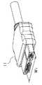
本発明の参考形態例のコネクタについて図1を参照して説明する。このレセプタクルコネクタ1は、上下方向に区切りがないタイプである。レセプタクルコネクタ1は、インシュレータ2と、インシュレータ2に保持される多数のコンタクト3と、インシュレータ2及び各コンタクト3を被覆するシェル4とから構成される。レセプタクルコネクタ1は、2種類の幅W1,W2の異なるプラグコネクタ11,12のいずれとも接続することができる。プラグコネクタ11,12は、それぞれフード11A,12Aにより包囲される。
【0020】
図2は、幅W1の相手側プラグコネクタ11である。
【0021】
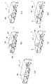
本発明の第1実施の形態例について図3を参照して説明する。参考形態例と相違する点のみについて説明し、同様の点の説明を省略する。このレセプタクルコネクタ1は、上下方向に区切りを有するタイプである。
【0022】
図3(a)は本発明の基本構成を示し、図3(a)に示されるように、シェル4の下部の中央を上方に向かって折曲して仕切り部4Gを形成する。仕切り部4Gの先端は、シェル4の上部内面に当接する。
【0023】
図3(b)と(c)は、レセプタクルコネクタ1の第1の設計変更例である。仕切り部4Gに2つの突起4Hを形成し、各突起4Hをシェル4の上部にあけた2つの孔4Iに挿入した後、各突起4Hを打ちつぶす。
【0024】
図3(d)と(e)は、レセプタクルコネクタ1の第2の設計変更例である。仕切り部4Gの1つの突起4Jをシェル4の上部にあけた1つの孔4Kに挿入した後、突起4Jを折曲する。
【0025】
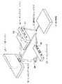
図4は、本発明の標準化されたコネクタを用いて周辺機器とノート型パソコンとを接続する場合の斜視図を示す。
【0026】
周辺機器21は、従来の技術と同様に、標準化されたコネクタ22と、ポートリプリケータ23のコネクタ24,25又はドッキングステーション26のコネクタ27,28と、ドッキングコネクタ30を介してノート型パソコン29と接続することができる。更に、本発明においては、標準化されたコネクタ22を直接ドッキングコネクタ30に接続することもできる。
【0027】
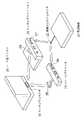
図5は、本発明のコネクタを、高解像度ディスプレイとDVC等との接続、及び、低解像度ディスプレイとパソコンとの接続に使用する場合の模式図である。
【0028】
高解像度ディスプレイ31とDVC等44とを低解像度用ケーブル42と高解像度用コネクタ33及び低解像度用コネクタ43を使用して接続する。また、低解像度ディスプレイ41とパソコン34とを低解像度用ケーブル42と低解像度用コネクタ43及び高解像度用コネクタ33を使用して接続する。
【0029】
【発明の効果】
以上の説明から明らかなように、本発明によれば、次の効果を奏することができる。
【0030】
1.複数の機能を一つに統合したコネクタを持つ機器が、その複数機能の一部に含まれる標準化されたコネクタのみを独立して接続可能とすることによって、本来、複数の機能を接続させるために存在するコネクタのスペースを利用して、標準化されている非常にポピュラーなコネクタをそのまま利用して、その一部の機能を利用することができる。例えば、ノート型パソコンのドッキングコネクタは、複数の機能を一つに統合したコネクタを持つ。外出する場合には、ノート型パソコンのみを持ち歩くケースが多いが、その場合にこの複数の機能を一つに統合したコネクタは、単にスペースを占有するのみの存在となっている。本発明を採用すれば、そのコネクタスペースを有効に活用することが可能となり、かつ、その一部の機能のコネクタは標準化されたものであれば、なんら特別な部材を準備することなく、利用することが可能となる(図4と図6参照)。
【0031】
2.TV、PDP、VIDEO、DVC、DVD、GAMEに代表される民生市場は低解像度ディスプレイが主力である。民生市場のみを対象とした場合、必要最小限のチャンネルを伝送可能な芯数のコネクタが採用可能である。一方PC市場は高解像度ディスプレイ対応が必要であり、それに対応した複数のチャンネルを伝送可能な芯数のコネクタを採用する必要がある。このように別々のニーズを持った市場に互換性を持たせるには、従来の方法では、ドングルコネクタか、両端が別々なコネクタのケーブルが必要になる。本発明では、チャンネル数の多い高解像度用に対応したコネクタにチャンネル数の少ない低解像度用のコネクタが嵌合可能とすることによって、最もシンプルに別々のニーズの市場を融合させることが可能となる。即ち、民生市場のみで利用する場合は、必要最小限のチャンネルを伝送可能な芯数のコネクタを採用し、PC市場のみで利用する場合は、複数のチャンネルを伝送可能な芯数のコネクタを採用する。また、一方の機器が民生市場、他方がPC市場の場合、PC市場側の複数のチャンネルを伝送可能な芯数のコネクタに、必要最小限のチャンネルを伝送可能な芯数のコネクタが直接嵌合可能とすることによって、その他の特別な手法を一切用いることなく両市場が融合可能となる。
【0032】
3.上記に採用されるコネクタについて、一部の信号と他の信号との間に、空間を隔離する壁(即ち仕切り部)をもたせることによって、複数のチャンネルを伝送可能な芯数のコネクタに一部の信号用コネクタが単独で嵌合する場合に、安定した性能を提供することができる。具体的には、コネクタの挿入、抜去時に、複数のチャンネルを伝送可能な芯数のコネクタ側に局部的に力が加わり、コネクタの破損が起こる場合がある。本発明のように、二つに空間に隔離する壁を持たせることによって、局部的な力に対する強度アップの効果を果たすことができる。
【0033】
4.相対する双方のコネクタ(リセプタクル、プラグ)が互いにシェルを持ち、一部の信号用コネクタのシェル端面と、全体の信号用コネクタのシェル端面にそれぞれに対する接触面を持つことによって、双方のコネクタ間でシェルの接触を保ち、グラウンドを強化することができる。
【図面の簡単な説明】
【図1】 本発明の参考形態例のレセプタクルコネクタと、これに接続する2種類の相手側プラグコネクタとの斜視図である。
【図2】相手側プラグコネクタの斜視図である。
【図3】本発明の第1実施の形態例のレセプタクルコネクタ及びその設計変更例の斜視図であり、(a)は同レセプタクルコネクタ、(b)は第1の設計変更例の突起を打ちつぶす前の状態、(c)は第1の設計変更例の突起を打ちつぶした後の状態、(d)は第2の設計変更例の突起を折曲する前の状態、(e)は第2の設計変更例の突起を折曲げした後の状態を、それぞれ示す。
【図4】本発明のコネクタを用いて周辺機器とノート型パソコンとを接続する場合の斜視図である。
【図5】本発明のコネクタを、高解像度ディスプレイとDVC等との接続、及び、低解像度ディスプレイとパソコンとの接続に使用する場合の模式図である。
【図6】従来のコネクタを用いて周辺機器とノート型パソコンとを接続する場合の斜視図である。
【図7】(a)は従来の高解像度用ケーブルと高解像度用コネクタを使用して高解像度ディスプレイとパソコンとを接続する場合の模式図である。
(b)は従来の低解像度用ケーブルと低解像度用コネクタを使用して低解像度ディスプレイとDVC等とを接続する場合の模式図である。
【図8】従来の低解像度用ケーブルと高解像度用コネクタ及び低解像度用コネクタを使用して、高解像度用ディスプレイとDVC等とを接続する場合と、低解像度用ディスプレイとパソコンとを接続する場合の模式図である。
【図9】従来の低解像度用ケーブルと高解像度用コネクタ、ドングルコネクタ及び低解像度用コネクタを使用して、高解像度用ディスプレイとDVC等とを接続する場合と、低解像度用ディスプレイとパソコンとを接続する場合の模式図である。
【符号の説明】
1 レセプタクルコネクタ
2 インシュレータ
3 コンタクト
4 シェル
4G 仕切り部
4H 突起
4I 孔
4J 突起
4K 孔
11 プラグコネクタ
11A フード
12 プラグコネクタ
12A フード
21 周辺機器
22 コネクタ
23 ポートリプリケータ
24 コネクタ
25 コネクタ
26 ドッキングステーション
27 コネクタ
28 コネクタ
29 ノート型パソコン
30 ドッキングコネクタ
31 高解像度ディスプレイ
32 高解像度用ケーブル
33 高解像度用コネクタ
34 パソコン
41 低解像度ディスプレイ
42 低解像度用ケーブル
43 低解像度用コネクタ
44 DVC等[0001]
BACKGROUND OF THE INVENTION
The present invention relates to a connector in which a fitting portion is divided into two or more parts, and more particularly to a connector that can be commonly used for low resolution and high resolution.
[0002]
[Prior art]
First, technical terms used in this specification will be described.
[0003]
TMDS is an abbreviation for Transition Minimized Differential Signaling. This is a standard for exchanging image data between a PC and a monitor (display), and is a form in which data transmission is performed using two signal lines (+, −) and one ground line.
[0004]
The serial transmission method refers to a method of transmitting information bit by bit using a single transmission line. On the other hand, for example, a method of simultaneously transmitting information for 8 bits using 8 transmission lines each is called a parallel transmission method.
[0005]
LVDS is an abbreviation for Low Voltage Differential Signaling. This is a type of high-speed serial transmission system that is mainly used for the input interface of the liquid crystal panel of notebook computers and liquid crystal monitors and transmits differential signals with small amplitude.
[0006]
GVIF is an abbreviation for Gigabit Video Interface. This is a type of high-speed serial transmission system that is used for input interfaces such as in-vehicle displays and that transmits differential signals using only a pair of paired wires.
[0007]
In high-speed video serial transmission represented by TMDS, LVDS, GVIF, etc., the number of channels differs depending on whether the display to be signaled is low resolution or high resolution. Conventionally, connectors for transmitting these signals include a low-resolution dedicated connector with a small number of channels and a connector that increases the number of channels and supports high-resolution.
[0008]
Of course, a connector that matches the number of channels for low resolution cannot transmit a signal for high resolution because the number of channels (number of signals) is insufficient. A connector that matches the number of channels for high resolution can also transmit signals for low resolution. However, the larger the number of signals, the larger the dimensions. In addition, the two connectors are not compatible, and a dongle connector or a cable with separate connectors at both ends is required.
[0009]
FIG. 6 is a perspective view when a peripheral device and a notebook personal computer are connected using a conventional standardized connector.
[0010]
The peripheral device 21 is connected to the notebook computer 29 via the standardized connector 22, the
[0011]
FIG. 7A is a schematic diagram in the case where the high-
[0012]
FIG . 7B is a schematic diagram when the low-
[0013]
FIG. 8 shows a case where a
[0014]
FIG. 9 shows a case where a
[0015]
[Problems to be solved by the invention]
Video high-speed serial transmission signals typified by TMDS, LVDS, GVIF, etc. have different numbers of channels depending on whether the display used for signal transmission has a low resolution or a high resolution. If the number of channels is adjusted for low resolution, the number of channels is insufficient for high resolution and transmission is not possible. When the number of channels is adjusted for high resolution, the outer shape of the connector increases as the number of channels increases. If you make separate connectors for each, they are not compatible with each other. An object of the present invention is to provide a connector with improved compatibility by allowing a connector for low resolution with a small number of channels to be fitted to a connector for high resolution with a large number of channels.
[0016]
[Means for Solving the Problems]
The present invention employs the following means in order to solve the above problems.
[0017]
1.In a connector comprising a plurality of contacts, an insulator holding each contact, and a shell covering each contact and the insulator, the connector includes a fitting portion connected to a fitting portion of a mating connector. The fitting part is formed by the shell, the fitting part is divided into a plurality of parts by the partition part, and each of the plurality of divided fitting parts is formed asymmetrically. The portion is bent from one inner surface of the shell and formed integrally with the shell so as to contact the other inner surface facing the one inner surface, the partition portion has a protrusion, and the shell has a hole. the protrusions are configured to protrude from the other outer surface of the shell is inserted into the hole, eachfittingsectionthat is dividedasymmetrically,each alone or, Wherein the fitting portion that is split is integrally engaged with the mating connector, the connector having a function of connecting.
[0018]
2.2. The connector according to 1, wherein the partitioning portion prevents erroneous insertion of the mating connector .
[0019]
DETAILED DESCRIPTION OF THE INVENTION
A connector according to a reference embodiment of the present invention will be described with reference to FIG. The receptacle connector 1 is of a type having no separation in the vertical direction. The receptacle connector 1 includes an insulator 2, a large number of contacts 3 held by the insulator 2, and a shell 4 that covers the insulator 2 and each contact 3. The receptacle connector 1 can be connected to any of the two types of
[0020]
Figure 2isa mating plug connector 11 having awidth W1.
[0021]
A first embodiment of the present invention will be described with reference to FIG. Only points different from the reference embodiment will be described, and description of similar points will be omitted. The receptacle connector 1 is a type having a partition in the vertical direction.
[0022]
FIG. 3A shows the basic configuration of the present invention. As shown in FIG. 3A, the center of the lower portion of the shell 4 is bent upward to form the
[0023]
FIGS. 3B and 3C show a first design modification example of the receptacle connector 1. Two
[0024]
FIGS. 3D and 3E show a second design modification example of the receptacle connector 1. After inserting one
[0025]
FIG. 4 shows a perspective view when a peripheral device and a notebook personal computer are connected using the standardized connector of the present invention.
[0026]
The peripheral device 21 is connected to the notebook personal computer 29 through the standardized connector 22, the
[0027]
FIG. 5 is aschematic diagram when the connector of the present invention is used for connection between a high resolution display and a DVC or the like, and between a low resolution display and a personal computer.
[0028]
The
[0029]
【The invention's effect】
As is clear from the above description, according to the present invention, the following effects can be obtained.
[0030]
1. In order to connect multiple functions originally, a device with a connector that integrates multiple functions into one can connect only the standardized connectors included in some of the multiple functions independently. By utilizing the existing connector space, the standardized very popular connector can be used as it is, and a part of the functions can be used. For example, a docking connector of a notebook computer has a connector that integrates a plurality of functions into one. When going out, there are many cases of carrying only a notebook personal computer. In that case, the connector that integrates the plurality of functions into one only occupies space. If the present invention is adopted, the connector space can be used effectively, and the connector of a part of the function can be used without preparing any special member as long as the connector is standardized. (See FIGS.4 and6 ).
[0031]
2. In the consumer market represented by TV, PDP, VIDEO, DVC, DVD, and GAME, low resolution displays are the mainstay. When only the consumer market is targeted, a connector having the number of cores capable of transmitting the minimum necessary channels can be employed. On the other hand, the PC market needs to be compatible with high-resolution displays, and it is necessary to adopt connectors with the number of cores that can transmit a plurality of channels corresponding to it. In order to provide compatibility in a market having different needs as described above, the conventional method requires a dongle connector or a cable having connectors at different ends. In the present invention, by allowing a connector for low resolution with a small number of channels to be fitted to a connector for high resolution with a large number of channels, it becomes possible to fuse the markets of different needs in the simplest manner. . In other words, when using only in the consumer market, a connector with the number of cores that can transmit the minimum number of channels is used. When using only in the PC market, a connector with the number of cores that can transmit multiple channels is used. To do. Also, when one device is in the consumer market and the other is in the PC market, the connector with the number of cores that can transmit the minimum number of channels is directly fitted to the connector with the number of cores that can transmit multiple channels on the PC market side. By enabling it, the two markets can be merged without using any other special method.
[0032]
3. About the connector adopted above, a part of the connector with the number of cores capable of transmitting a plurality of channels is provided by providing a wall (that is, a partition part) that separates a space between some signals and other signals. Stable performance can be provided when the signal connector is fitted alone. Specifically, when a connector is inserted or removed, a force may be locally applied to the connector having the number of cores capable of transmitting a plurality of channels, and the connector may be damaged. As in the present invention, the effect of increasing the strength against a local force can be achieved by providing two walls that separate the spaces.
[0033]
4 . Both opposing connectors (receptacles, plugs) have shells between them, and a shell end surface of some signal connectors and a contact surface to each of the shell end surfaces of the entire signal connectors make it possible to Keep the shell in contact and strengthen the ground.
[Brief description of the drawings]
FIG. 1 is a perspective view of a receptacle connector according to areference embodiment of the present invention and two types of mating plug connectors connected to the receptacle connector.
FIG. 2is a perspective view of a mating plug connector.
FIGS. 3A and 3Bare perspective views of a receptacle connector and a design change example thereof according to the first embodiment of the present invention, in which FIG. 3A isa receptacle connector and FIG. 3B is a projection of a projection of the first design change example; The previous state, (c) is the state after crushing the protrusion of the first design change example, (d) is the state before bending the protrusion of the second design change example, and (e) is the second state. The state after bending the protrusion of the design change example isshown.
FIG. 4is a perspective view when a peripheral device and a notebook computer are connected using the connector of the present invention.
FIG. 5 is a schematic diagram whenthe connector of the present invention is used for connection between a high resolution display and a DVC or the like, and between a low resolution display and a personal computer.
FIG. 6is a perspective view when a peripheral device and a notebook personal computer are connected using a conventional connector.
FIG.7A is a schematic diagram when a high-resolution display and a personal computer are connected using a conventional high-resolution cable and a high-resolution connector.
(B) is a schematic diagram when a low-resolution display is connected to a DVC or the like using a conventional low-resolution cable and a low-resolution connector.
FIG. 8 showsa case of connecting a high resolution display and a DVC using a conventional low resolution cable, a high resolution connector and a low resolution connector, and a case of connecting a low resolution display and a personal computer. FIG.
FIG. 9 showsa case where a high-resolution display is connected to a DVC using a conventional low-resolution cable, a high-resolution connector, a dongle connector, and a low-resolution connector, and a low-resolution display and a personal computer. It is a schematic diagram in the case of connecting.
[Explanation of symbols]
DESCRIPTION OF SYMBOLS 1 Receptacle connector 2 Insulator 3 Contact 4
Claims (2)
Translated fromJapanese前記コネクタは、相手側コネクタの嵌合部と接続する嵌合部を有し、該嵌合部は、前記シェルにより形成され、 The connector has a fitting portion connected to a fitting portion of a mating connector, and the fitting portion is formed by the shell,
該嵌合部は、仕切り部により複数に分割され、かつ、分割された複数の嵌合部のそれぞれは、非対称に形成され、 The fitting part is divided into a plurality by the partition part, and each of the divided fitting parts is formed asymmetrically.
前記仕切り部は、前記シェルの一方の内面から折り曲げ、前記一方の内面と対向する他方の内面に当接するように前記シェルと一体形成され、The partition portion is bent from one inner surface of the shell, and is integrally formed with the shell so as to contact the other inner surface facing the one inner surface,
前記仕切り部は突起を有し、前記シェルは孔を有し、前記突起が前記孔に挿入されて前記シェルの他方の外面から突出するように構成され、 The partition portion has a protrusion, the shell has a hole, and the protrusion is inserted into the hole and protrudes from the other outer surface of the shell,
非対称に分割された前記各嵌合部は、それぞれが単独で、又は、分割された前記各嵌合部が一体で、前記相手側コネクタと嵌合し、接続する機能を有することを特徴とするコネクタ。 Each of the fitting parts divided asymmetrically has a function of being connected to each other connector and connecting each of the divided fitting parts alone or with each other. connector.
Priority Applications (8)
| Application Number | Priority Date | Filing Date | Title |
|---|---|---|---|
| JP2001203992AJP3761428B2 (en) | 2001-07-04 | 2001-07-04 | connector |
| US10/187,684US6939177B2 (en) | 2001-07-04 | 2002-07-02 | Connector for plural mating connectors having different shapes of interfaces |
| DK02014811TDK1274155T3 (en) | 2001-07-04 | 2002-07-02 | Connector for multiple, paired connectors, which connector has different interface shapes |
| EP02014811AEP1274155B1 (en) | 2001-07-04 | 2002-07-02 | Connector for plural mating connectors having different shapes of interfaces |
| DE60216194TDE60216194T2 (en) | 2001-07-04 | 2002-07-02 | Connector for coupling with different connectors showing different adjustment forms |
| TW091114738ATWI258897B (en) | 2001-07-04 | 2002-07-03 | Connector for plural mating connectors having different shapes of interfaces |
| KR1020020038247AKR100571720B1 (en) | 2001-07-04 | 2002-07-03 | Connector for plural mating connectors having different shapes of interfaces |
| CNB021411093ACN1194449C (en) | 2001-07-04 | 2002-07-04 | Connectors for a variety of mating connectors with different interface shapes |
Applications Claiming Priority (1)
| Application Number | Priority Date | Filing Date | Title |
|---|---|---|---|
| JP2001203992AJP3761428B2 (en) | 2001-07-04 | 2001-07-04 | connector |
Publications (2)
| Publication Number | Publication Date |
|---|---|
| JP2003017165A JP2003017165A (en) | 2003-01-17 |
| JP3761428B2true JP3761428B2 (en) | 2006-03-29 |
Family
ID=19040538
Family Applications (1)
| Application Number | Title | Priority Date | Filing Date |
|---|---|---|---|
| JP2001203992AExpired - Fee RelatedJP3761428B2 (en) | 2001-07-04 | 2001-07-04 | connector |
Country Status (8)
| Country | Link |
|---|---|
| US (1) | US6939177B2 (en) |
| EP (1) | EP1274155B1 (en) |
| JP (1) | JP3761428B2 (en) |
| KR (1) | KR100571720B1 (en) |
| CN (1) | CN1194449C (en) |
| DE (1) | DE60216194T2 (en) |
| DK (1) | DK1274155T3 (en) |
| TW (1) | TWI258897B (en) |
Families Citing this family (96)
| Publication number | Priority date | Publication date | Assignee | Title |
|---|---|---|---|---|
| USD478320S1 (en) | 2002-06-10 | 2003-08-12 | Japan Aviation Electronics Industry, Limited | Electrical connector |
| USD482002S1 (en) | 2002-06-10 | 2003-11-11 | Japan Aviation Electronics Industry, Limited | Electrical connector |
| JP4223771B2 (en)* | 2002-09-02 | 2009-02-12 | 日本圧着端子製造株式会社 | Reverse mating prevention connector |
| KR20040022640A (en)* | 2002-09-09 | 2004-03-16 | 삼성전자주식회사 | computer system and method for transmitting data thereof |
| US7627343B2 (en) | 2003-04-25 | 2009-12-01 | Apple Inc. | Media player system |
| US7624218B2 (en)* | 2003-10-20 | 2009-11-24 | Dell Products L.P. | System and method for DVI native and docking support |
| US7529871B1 (en) | 2004-04-27 | 2009-05-05 | Apple Inc. | Communication between an accessory and a media player with multiple protocol versions |
| US7526588B1 (en) | 2004-04-27 | 2009-04-28 | Apple Inc. | Communication between an accessory and a media player using a protocol with multiple lingoes |
| US7634605B2 (en) | 2004-04-27 | 2009-12-15 | Apple Inc. | Method and system for transferring stored data between a media player and an accessory |
| US7826318B2 (en) | 2004-04-27 | 2010-11-02 | Apple Inc. | Method and system for allowing a media player to transfer digital audio to an accessory |
| US8117651B2 (en) | 2004-04-27 | 2012-02-14 | Apple Inc. | Method and system for authenticating an accessory |
| US7441058B1 (en) | 2006-09-11 | 2008-10-21 | Apple Inc. | Method and system for controlling an accessory having a tuner |
| US7441062B2 (en) | 2004-04-27 | 2008-10-21 | Apple Inc. | Connector interface system for enabling data communication with a multi-communication device |
| US7529872B1 (en) | 2004-04-27 | 2009-05-05 | Apple Inc. | Communication between an accessory and a media player using a protocol with multiple lingoes |
| US7895378B2 (en) | 2004-04-27 | 2011-02-22 | Apple Inc. | Method and system for allowing a media player to transfer digital audio to an accessory |
| US7529870B1 (en) | 2004-04-27 | 2009-05-05 | Apple Inc. | Communication between an accessory and a media player with multiple lingoes |
| US7673083B2 (en) | 2004-04-27 | 2010-03-02 | Apple Inc. | Method and system for controlling video selection and playback in a portable media player |
| US7293122B1 (en) | 2004-04-27 | 2007-11-06 | Apple Inc. | Connector interface system facilitating communication between a media player and accessories |
| US7797471B2 (en) | 2004-04-27 | 2010-09-14 | Apple Inc. | Method and system for transferring album artwork between a media player and an accessory |
| EP1774624A1 (en)* | 2004-07-07 | 2007-04-18 | Molex Incorporated | Keyed housing for use with small size plug connectors |
| US7823214B2 (en) | 2005-01-07 | 2010-10-26 | Apple Inc. | Accessory authentication for electronic devices |
| US7525216B2 (en) | 2005-01-07 | 2009-04-28 | Apple Inc. | Portable power source to provide power to an electronic device via an interface |
| GB2439706B (en)* | 2005-05-04 | 2010-04-07 | Acco Brands Usa Llc | A connector for a computer and a system comprising a connector |
| US7128614B1 (en)* | 2005-06-03 | 2006-10-31 | Hon Hai Precision Ind. Co., Ltd. | Electrical adapter with reinforcing member |
| US7331824B2 (en)* | 2005-06-03 | 2008-02-19 | Hon Hai Precision Ind. Co., Ltd. | Cable connector assembly with wire spacer |
| JP4665674B2 (en)* | 2005-09-02 | 2011-04-06 | ミツミ電機株式会社 | connector |
| CN1992447A (en)* | 2005-12-29 | 2007-07-04 | 富士康(昆山)电脑接插件有限公司 | Electrical connector assembly |
| US7670181B2 (en) | 2006-03-20 | 2010-03-02 | Htc Corporation | Connector for first and second joints having different pin quantities, electronic apparatus with connector and combination |
| US7632114B2 (en) | 2006-03-30 | 2009-12-15 | Apple Inc. | Interface connecter between media player and other electronic devices |
| US8006019B2 (en) | 2006-05-22 | 2011-08-23 | Apple, Inc. | Method and system for transferring stored data between a media player and an accessory |
| CN100490258C (en) | 2006-05-24 | 2009-05-20 | 宏达国际电子股份有限公司 | Connector for sharing first type connector and second type connector with different pin numbers |
| US20070296461A1 (en)* | 2006-06-26 | 2007-12-27 | Radiospire Networks, Inc. | System, method and apparatus for transmitting and receiving a transition minimized differential signal |
| US7415563B1 (en) | 2006-06-27 | 2008-08-19 | Apple Inc. | Method and system for allowing a media player to determine if it supports the capabilities of an accessory |
| USD548700S1 (en)* | 2006-08-17 | 2007-08-14 | Microsoft Corporation | Portion of a cabling assembly |
| US7558894B1 (en) | 2006-09-11 | 2009-07-07 | Apple Inc. | Method and system for controlling power provided to an accessory |
| USD586297S1 (en)* | 2007-08-03 | 2009-02-10 | Japan Aviation Electronics Industry, Limited | Electrical connector |
| US8095713B2 (en) | 2007-09-04 | 2012-01-10 | Apple Inc. | Smart cables |
| USD585835S1 (en)* | 2007-10-30 | 2009-02-03 | Bretford Manufacturing, Inc. | Power cord |
| US8047966B2 (en) | 2008-02-29 | 2011-11-01 | Apple Inc. | Interfacing portable media devices and sports equipment |
| USD604737S1 (en)* | 2008-03-03 | 2009-11-24 | Blue Lounge Design, Llc | Extended desk organizer for notebook computers |
| JP5015826B2 (en)* | 2008-03-04 | 2012-08-29 | タイコエレクトロニクスジャパン合同会社 | Electrical connector |
| US8057259B2 (en)* | 2008-04-08 | 2011-11-15 | Mitsumi Electric Co., Ltd | Receptacle connector, plug connector and connector apparatus |
| CN100589290C (en)* | 2008-05-12 | 2010-02-10 | 王鸿 | Portable multifunctional data storage transmission connection device |
| JP4519181B2 (en) | 2008-05-14 | 2010-08-04 | ヒロセ電機株式会社 | connector |
| US20090291597A1 (en)* | 2008-05-21 | 2009-11-26 | Dell Products, Lp | Method and apparatus to couple an external device to, and power the external device from, an information handling system |
| US8208853B2 (en) | 2008-09-08 | 2012-06-26 | Apple Inc. | Accessory device authentication |
| US8238811B2 (en) | 2008-09-08 | 2012-08-07 | Apple Inc. | Cross-transport authentication |
| CN101673903B (en)* | 2008-09-09 | 2013-05-08 | 富士康(昆山)电脑接插件有限公司 | Electric connector and electric connector assembly |
| CN201323329Y (en)* | 2008-10-14 | 2009-10-07 | 富士康(昆山)电脑接插件有限公司 | Electric connector |
| CN201323356Y (en) | 2008-11-03 | 2009-10-07 | 富士康(昆山)电脑接插件有限公司 | Plug electric connector |
| US7614920B1 (en) | 2008-11-17 | 2009-11-10 | Hon Hai Precision Ind. Co., Ltd. | Electrical connector with improved mating port for high speed signal transmission |
| USD641367S1 (en)* | 2008-12-19 | 2011-07-12 | Deutsche Telekom Ag | Docking station |
| USD635978S1 (en)* | 2009-02-19 | 2011-04-12 | Aten International Co., Ltd. | KVMP switch system |
| TW201101595A (en)* | 2009-06-16 | 2011-01-01 | Tyco Holdings Bermuda No 7 Ltd | Electrical connector |
| JP5402326B2 (en)* | 2009-07-07 | 2014-01-29 | ミツミ電機株式会社 | connector |
| CN102044818B (en)* | 2009-10-14 | 2013-06-12 | 广濑电机株式会社 | Connector |
| JP5312288B2 (en)* | 2009-10-27 | 2013-10-09 | ホシデン株式会社 | Shield case and connector provided with the same |
| KR101701922B1 (en) | 2009-11-17 | 2017-02-02 | 삼성전자 주식회사 | Docking apparatus for portable device |
| US8719112B2 (en)* | 2009-11-24 | 2014-05-06 | Microsoft Corporation | Invocation of accessory-specific user experience |
| US7865629B1 (en)* | 2009-11-24 | 2011-01-04 | Microsoft Corporation | Configurable connector for system-level communication |
| US8007320B1 (en)* | 2010-02-08 | 2011-08-30 | Hon Hai Precision Ind. Co., Ltd | Complex electrical connector |
| JP5525332B2 (en)* | 2010-05-20 | 2014-06-18 | ホシデン株式会社 | Shield case, connector and electronic equipment |
| TWI508393B (en)* | 2010-03-26 | 2015-11-11 | Hosiden Corp | Connectors and electronic machines |
| JP5388922B2 (en)* | 2010-03-26 | 2014-01-15 | ホシデン株式会社 | Connectors and electronic devices |
| JP5567882B2 (en)* | 2010-03-31 | 2014-08-06 | 第一電子工業株式会社 | Electrical connector |
| JP2011233326A (en)* | 2010-04-27 | 2011-11-17 | Hosiden Corp | Shield case and connector |
| CN102290655B (en)* | 2010-06-21 | 2013-12-04 | 富士康(昆山)电脑接插件有限公司 | Electric connector |
| CN102290654B (en)* | 2010-06-21 | 2014-02-19 | 富士康(昆山)电脑接插件有限公司 | electrical connector |
| TW201207625A (en)* | 2010-08-06 | 2012-02-16 | Hon Hai Prec Ind Co Ltd | Serial port transmission device |
| CN102157854A (en)* | 2010-12-23 | 2011-08-17 | 吴江奇才电子科技有限公司 | Multifunctional joint for automobile video cables |
| TWI455422B (en) | 2011-05-20 | 2014-10-01 | Molex Inc | Socket connector |
| TWI479324B (en)* | 2012-01-05 | 2015-04-01 | Wistron Corp | Connection interface and transmission line |
| CN103456342A (en)* | 2012-05-30 | 2013-12-18 | 凡甲电子(苏州)有限公司 | Portable data storage device |
| USD717799S1 (en)* | 2012-09-05 | 2014-11-18 | Samsung Electronics Co., Ltd. | Digital clipboard reader |
| US9160124B2 (en) | 2012-09-07 | 2015-10-13 | Apple Inc. | Compliant mount for connector |
| US8721356B2 (en) | 2012-09-11 | 2014-05-13 | Apple Inc. | Dock with compliant connector mount |
| US8986029B2 (en) | 2012-09-11 | 2015-03-24 | Apple Inc. | Dock connector with compliance mechanism |
| CN104078806A (en)* | 2013-03-29 | 2014-10-01 | 倚新科技股份有限公司 | Connectors and how to use them |
| KR20150026661A (en)* | 2013-09-03 | 2015-03-11 | 삼성전자주식회사 | Connector device |
| TWM489394U (en)* | 2014-05-08 | 2014-11-01 | Advanced Connectek Inc | Micro-plug electrical connector |
| CN104319575B (en)* | 2014-10-31 | 2017-03-22 | 昆山德朋电子科技有限公司 | Double-interface electric connector |
| JP2016115562A (en)* | 2014-12-16 | 2016-06-23 | Smk株式会社 | Electrical connector |
| US9455540B2 (en)* | 2015-01-19 | 2016-09-27 | Aimmet Industrial Co., Ltd. | High-speed signal transmission device |
| US10282337B2 (en) | 2015-02-27 | 2019-05-07 | Google Llc | Multi-function ports on a computing device |
| US10152442B2 (en) | 2015-02-27 | 2018-12-11 | Google Llc | Multi-function ports on a computing device |
| WO2018052430A1 (en) | 2016-09-15 | 2018-03-22 | Hewlett-Packard Development Company, L.P. | Connectors |
| CN206236856U (en)* | 2016-09-22 | 2017-06-09 | 番禺得意精密电子工业有限公司 | Composite connector |
| US10468842B2 (en)* | 2017-01-12 | 2019-11-05 | Ortronics, Inc. | Expandable audio visual adapter module with multi-port voltage and power management circuitry |
| WO2019030336A1 (en)* | 2017-08-10 | 2019-02-14 | Koninklijke Philips N.V. | Connectors for ultrasound imaging system |
| CN107978943A (en)* | 2017-12-01 | 2018-05-01 | 上海航天科工电器研究院有限公司 | A kind of differential signal of transferring is the adapter of double round bar terminal or coaxial terminal outputs |
| CN109687210B (en)* | 2018-01-02 | 2021-04-27 | 嘉基电子科技(苏州)有限公司 | Electric connector combination |
| US11336053B2 (en) | 2018-02-27 | 2022-05-17 | Hewlett-Packard Development Company, L.P. | Data carrier adapters |
| CN110380300B (en)* | 2018-04-13 | 2024-11-15 | 比亚迪股份有限公司 | In-vehicle display terminal and vehicle |
| USD868742S1 (en)* | 2018-06-07 | 2019-12-03 | Dongguan Leshi Electronic & Technology Co., Ltd | Headphone adapter |
| CN110854602B (en)* | 2019-11-25 | 2022-01-25 | 中航光电科技股份有限公司 | Multi-purpose plugged multi-cavity rectangular modular connector |
| CN115864080A (en)* | 2021-09-23 | 2023-03-28 | 昆山德朋电子科技有限公司 | electrical connection device |
Family Cites Families (15)
| Publication number | Priority date | Publication date | Assignee | Title |
|---|---|---|---|---|
| US4597631A (en) | 1982-12-02 | 1986-07-01 | The United States Of America As Represented By The Secretary Of The Navy | Printed circuit card hybrid |
| US5234353A (en)* | 1992-03-03 | 1993-08-10 | Amp Incorporated | Hybrid input/output connector having low mating force and high cycle life and contacts therefor |
| IE922722A1 (en)* | 1992-10-09 | 1994-04-20 | Molex Inc | Electrical connector system |
| GB2293283B (en)* | 1994-09-09 | 1999-02-24 | Nokia Mobile Phones Ltd | Combined connector contact |
| US5685739A (en)* | 1996-02-14 | 1997-11-11 | The Whitaker Corporation | Shielded electrical connector |
| US6024607A (en)* | 1998-06-12 | 2000-02-15 | Hewlett-Packard Company | Female combination connector |
| FR2781094B1 (en)* | 1998-07-09 | 2000-08-18 | Alsthom Cge Alcatel | MIXED CONNECTION ASSEMBLY |
| US6139367A (en)* | 1999-08-03 | 2000-10-31 | Hon Hai Precision Ind. Co., Ltd. | Shielded electrical connector |
| US6558201B1 (en)* | 1999-10-20 | 2003-05-06 | Hewlett Packard Development Company, L.P. | Adapter and method for converting data interface hardware on a computer peripheral device |
| US6231390B1 (en)* | 1999-10-21 | 2001-05-15 | Hon Hai Precision Ind. Co., Ltd. | Connector for use in portable phone |
| TW433609U (en) | 1999-10-29 | 2001-05-01 | Hon Hai Prec Ind Co Ltd | Electrical connector |
| US6305986B1 (en)* | 2000-05-18 | 2001-10-23 | Hon Hai Precision Ind. Co., Ltd. | Cable connector assembly having improved grounding means |
| TW460050U (en)* | 2000-10-20 | 2001-10-11 | Hon Hai Prec Ind Co Ltd | Electrical connector assembly |
| US6758697B1 (en)* | 2003-03-10 | 2004-07-06 | Hon Hai Precision Ind. Co., Ltd. | Electrical adapter |
| US6758685B1 (en)* | 2003-04-11 | 2004-07-06 | Compal Electronics, Inc. | Serial advanced technology attachment connector |
- 2001
- 2001-07-04JPJP2001203992Apatent/JP3761428B2/ennot_activeExpired - Fee Related
- 2002
- 2002-07-02DEDE60216194Tpatent/DE60216194T2/ennot_activeExpired - Lifetime
- 2002-07-02USUS10/187,684patent/US6939177B2/ennot_activeExpired - Lifetime
- 2002-07-02DKDK02014811Tpatent/DK1274155T3/enactive
- 2002-07-02EPEP02014811Apatent/EP1274155B1/ennot_activeExpired - Lifetime
- 2002-07-03TWTW091114738Apatent/TWI258897B/ennot_activeIP Right Cessation
- 2002-07-03KRKR1020020038247Apatent/KR100571720B1/ennot_activeExpired - Fee Related
- 2002-07-04CNCNB021411093Apatent/CN1194449C/ennot_activeExpired - Fee Related
Also Published As
| Publication number | Publication date |
|---|---|
| EP1274155A1 (en) | 2003-01-08 |
| KR100571720B1 (en) | 2006-04-18 |
| CN1194449C (en) | 2005-03-23 |
| KR20030004134A (en) | 2003-01-14 |
| DE60216194D1 (en) | 2007-01-04 |
| JP2003017165A (en) | 2003-01-17 |
| DE60216194T2 (en) | 2007-10-04 |
| CN1395342A (en) | 2003-02-05 |
| EP1274155B1 (en) | 2006-11-22 |
| US6939177B2 (en) | 2005-09-06 |
| US20030008566A1 (en) | 2003-01-09 |
| TWI258897B (en) | 2006-07-21 |
| DK1274155T3 (en) | 2007-04-02 |
Similar Documents
| Publication | Publication Date | Title |
|---|---|---|
| JP3761428B2 (en) | connector | |
| US7467977B1 (en) | Electrical connector with additional mating port | |
| EP1434318A2 (en) | Electrical cable assembly | |
| US20130217274A1 (en) | Connector for achieving complete interoperability between different types of data and multimedia interfaces | |
| TWI685161B (en) | Adapter | |
| AU2020359756B2 (en) | Connector, electronic device and open pluggable specification (OPS) device | |
| US7783801B2 (en) | KVM console cable and multi-computer system using the same | |
| US9893475B2 (en) | Connector system capable of mitigating signal deterioration | |
| US20080174595A1 (en) | Controlled impedance display adapter | |
| EP2991171B1 (en) | Connector, data transmission device, data reception device, and data transmission and reception system | |
| US7963809B2 (en) | Microdvi connector | |
| US20070072491A1 (en) | Integrated signal connecting port | |
| US6923683B2 (en) | High density interconnection device | |
| CN201061051Y (en) | Multi-port connector combining HDMI and USB transmission interfaces | |
| US20140177185A1 (en) | Wall plate assembly with signal-adaptive features | |
| JP3145665U (en) | Socket connector | |
| KR200399441Y1 (en) | Multi-USB gender | |
| KR200493580Y1 (en) | Video connector with mutually engaged two-piece plastic structure | |
| KR20010098358A (en) | Connector in which a number of contacts are grouped into a plurality of contact groups according to intended uses | |
| CN216672112U (en) | Cable assembly and cable assembly connecting system | |
| CN201252304Y (en) | multi-port connector | |
| CN201113086Y (en) | Multi-port connector integrating image display connection port and USB transmission interface | |
| CN201126909Y (en) | multiport connector | |
| CN210779364U (en) | Built-in line with two TYPE-C connectors | |
| JP3100578U (en) | Rotating network cable connector |
Legal Events
| Date | Code | Title | Description |
|---|---|---|---|
| A977 | Report on retrieval | Free format text:JAPANESE INTERMEDIATE CODE: A971007 Effective date:20031126 | |
| A131 | Notification of reasons for refusal | Free format text:JAPANESE INTERMEDIATE CODE: A131 Effective date:20040225 | |
| A521 | Written amendment | Free format text:JAPANESE INTERMEDIATE CODE: A523 Effective date:20040420 | |
| A02 | Decision of refusal | Free format text:JAPANESE INTERMEDIATE CODE: A02 Effective date:20050928 | |
| A521 | Written amendment | Free format text:JAPANESE INTERMEDIATE CODE: A523 Effective date:20051118 | |
| A911 | Transfer of reconsideration by examiner before appeal (zenchi) | Free format text:JAPANESE INTERMEDIATE CODE: A911 Effective date:20051129 | |
| TRDD | Decision of grant or rejection written | ||
| A01 | Written decision to grant a patent or to grant a registration (utility model) | Free format text:JAPANESE INTERMEDIATE CODE: A01 Effective date:20051228 | |
| A61 | First payment of annual fees (during grant procedure) | Free format text:JAPANESE INTERMEDIATE CODE: A61 Effective date:20060110 | |
| R150 | Certificate of patent or registration of utility model | Free format text:JAPANESE INTERMEDIATE CODE: R150 | |
| FPAY | Renewal fee payment (event date is renewal date of database) | Free format text:PAYMENT UNTIL: 20100120 Year of fee payment:4 | |
| FPAY | Renewal fee payment (event date is renewal date of database) | Free format text:PAYMENT UNTIL: 20100120 Year of fee payment:4 | |
| FPAY | Renewal fee payment (event date is renewal date of database) | Free format text:PAYMENT UNTIL: 20100120 Year of fee payment:4 | |
| FPAY | Renewal fee payment (event date is renewal date of database) | Free format text:PAYMENT UNTIL: 20110120 Year of fee payment:5 | |
| FPAY | Renewal fee payment (event date is renewal date of database) | Free format text:PAYMENT UNTIL: 20110120 Year of fee payment:5 | |
| FPAY | Renewal fee payment (event date is renewal date of database) | Free format text:PAYMENT UNTIL: 20120120 Year of fee payment:6 | |
| FPAY | Renewal fee payment (event date is renewal date of database) | Free format text:PAYMENT UNTIL: 20120120 Year of fee payment:6 | |
| FPAY | Renewal fee payment (event date is renewal date of database) | Free format text:PAYMENT UNTIL: 20130120 Year of fee payment:7 | |
| FPAY | Renewal fee payment (event date is renewal date of database) | Free format text:PAYMENT UNTIL: 20130120 Year of fee payment:7 | |
| FPAY | Renewal fee payment (event date is renewal date of database) | Free format text:PAYMENT UNTIL: 20130120 Year of fee payment:7 | |
| FPAY | Renewal fee payment (event date is renewal date of database) | Free format text:PAYMENT UNTIL: 20130120 Year of fee payment:7 | |
| FPAY | Renewal fee payment (event date is renewal date of database) | Free format text:PAYMENT UNTIL: 20140120 Year of fee payment:8 | |
| R250 | Receipt of annual fees | Free format text:JAPANESE INTERMEDIATE CODE: R250 | |
| R250 | Receipt of annual fees | Free format text:JAPANESE INTERMEDIATE CODE: R250 | |
| R250 | Receipt of annual fees | Free format text:JAPANESE INTERMEDIATE CODE: R250 | |
| R250 | Receipt of annual fees | Free format text:JAPANESE INTERMEDIATE CODE: R250 | |
| LAPS | Cancellation because of no payment of annual fees |