JP3760052B2 - Continuous bag with synthetic resin chuck - Google Patents
Continuous bag with synthetic resin chuckDownload PDFInfo
- Publication number
- JP3760052B2 JP3760052B2JP26945998AJP26945998AJP3760052B2JP 3760052 B2JP3760052 B2JP 3760052B2JP 26945998 AJP26945998 AJP 26945998AJP 26945998 AJP26945998 AJP 26945998AJP 3760052 B2JP3760052 B2JP 3760052B2
- Authority
- JP
- Japan
- Prior art keywords
- seal
- chuck
- bag
- flattened portion
- continuous bag
- Prior art date
- Legal status (The legal status is an assumption and is not a legal conclusion. Google has not performed a legal analysis and makes no representation as to the accuracy of the status listed.)
- Expired - Fee Related
Links
Images

Landscapes
- Bag Frames (AREA)
- Making Paper Articles (AREA)
Description
Translated fromJapanese【0001】
【発明の属する技術分野】
本発明は、開口部に再開閉可能なチャックを備えたチャック付袋体を複数連続した合成樹脂製チャック付の連続袋に関するものである。
【0002】
【従来の技術】
製袋、充填作業の合理化、取り扱いの能率向上、検体等の整理分析や部品類の区分けといった具体的用途等に、チャック付連続袋及びその製造方法が、特公昭46−15346号公報、特公昭49−47547号公報等で提供され、広範囲の分野で使用されている。
【0003】
この連続袋は製袋、充填作業工程等においては連続形態を保持するに足る連結強度が要求される反面、需要者においては連結箇所の引きちぎりが出来るだけ容易であることが要求される。
【0004】
そこで、特公昭49−47547号公報でみられるように、チャックとサイドシール部との交差部分を平坦に押し潰したポイントシールにより扁平化し、隣接する複数のチャック付袋体を区画するサイドシール部にはミシン目を施したものがある。
【0005】
【発明が解決しようとする課題】
しかしながら、チャック部分が肉厚であるために、ポイントシールを施したときに扁平化部に段差が残り易く、この段差の影響によって扁平化部周辺サイドシールが弱くなるところが生じて気密性が損なわれる不具合がある。
【0006】
本発明の目的は、サイドシール部にミシン目を施した連続袋体において、気密性を確保した合成樹脂製チャック付の連続袋を提供することである。
【0007】
【課題を解決するための手段】
上記目的を達成するため本発明は、内層に易シール性樹脂を使用した複層の対面する袋体フィルムの内側面に再開閉可能なチャックを備え、このチャックと交差したサイドシール部により隣接する複数のチャック付袋体を区画し、前記チャックとサイドシールとの交差部を押圧扁平化したポイントシール扁平化部を備え、前記サイドシール部に前記チャックと交差する方向に前記扁平化部と隣接する部域を横断するようにしてミシン目シールを施した連続袋において、前記ミシン目シールは、そのミシン目が前記ポイントシール扁平化部の一部と、ポイントシール扁平化部と隣接するサイドシールが脆弱となる部分の部域を横断するように施したことを特徴とするものである。
【0008】
また、前記袋体フィルムがシール温度差を有する内外複層のフィルムによって形成されており、内層に低温シール層が用いられていることを特徴とするものである。
【0009】
さらに、前記ポイントシール扁平化部とその近傍において、前記ミシン目シールのミシン目の長さを適宜調整するようにして、ミシン目シールが前記扁平化部と隣接する部域を横断するようにしたことを特徴とするものである。
【0010】
【発明の実施の形態】
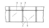
以下本発明の実施の形態を図面に基づいて説明する。図1において、1は複数枚の袋体が連なっている連続袋である。2は雌雄咬合具の再開閉可能なチャックであり、内層に易シール性樹脂を使用した複層のフィルムによる対面する袋体フィルムの内側面に設けられている。
【0011】
前記連続袋1は、隣接する各袋体を区画する所定幅のサイドシール部3によって連続的に形成され、これらサイドシール部3と前記チャック2の交差部分又は該交差部分とその周辺部は押し潰しのポイントシールによって扁平化された扁平化部4が形成されている。また、前記区画サイドシール部3には引きちぎりを容易にするために切取線条痕若しくはミシン目等の引きちぎり切り取り手段が施されている。
【0012】
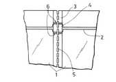
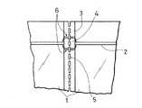
本発明は前記のような連続袋1において、サイドシール部3を引きちぎりを容易にするために前記扁平化部4を含めて前記チャック2と交差する方向でミシン目シール5を施したものである。すなわち、前記ミシン目シール5は図2,図3及び図4で示すように、前記扁平化部4とこれと隣接する部域を横断するように施されているものである。尚、ミシン目シール5は図示されるようにサイドシール部3の長手方向全長に渡るものであっても良い。
【0013】
前記ミシン目シール5は、単なる打ち抜きのミシン目とは異なり、溶断することにより図4で示すように、ミシン目穴の縁周囲に溶着部5aが形成されて気密状になっている形態である。
【0014】
また、前記ミシン目シール5のミシン目の長さは図2及び図3で示すように、必要に応じて適宜調整される。
【0015】
さらに、本発明は、前記のような連続袋1において、袋体フィルムがシール温度差を有する内層フィルムと外層フィルムとによって形成される。例えば、内層フィルムにPE系コポリマーを使用して低温シール層とし、外層フィルムにシール温度差が5℃以上、望ましくは15℃〜20℃以上のフィルムを用いる。尚、内層フィルムを低密度ポリエチレン(LDPE)とし外層フィルムを高密度ポリエチレン(HDPE)の組み合わせでもよい。こうすることにより、生産のスピードアップによる低コスト化を実現し、また、袋体表面の熱劣化による汚損の問題を解消する。
【0016】
従来では図2及び図3で示すように、ポイントシールを施したときに扁平化部4に段差が残り易く、この段差の影響によって扁平化部4周辺にサイドシールが弱くなる部分6が生じて気密性を損なう因となり易かったが、本発明は上記の通りの構造であるから、ミシン目シール5が扁平化部4と隣接するサイドシールが弱くなる部分6の部域を横断するように施されているため、この部分は所定幅のサイドシール部3とミシン目シール5との2重シール構造となり、段差の影響によってサイドシールが弱くなる部分6が生じて気密性が損なわれがちな扁平化部4の周辺における気密性を確保することができる。
【0017】
また、前記ミシン目シール5のミシン目の長さを調整することによって前記サイドシールが弱くなる部分6の範囲を適格に押さえて気密性を確保することができると共に、要求される条件に応じ、例えば連続袋の連結部に連続形態を維持するのに必要な強度を持たせたり、あるいは個々の袋体とする引きちぎりを容易にすることができる。
【0018】
さらに、本発明の連続袋1においては、袋体フィルムを内層に易シール性樹脂を使用した複層フィルムとし、内外複層フィルムにシール温度差を持たせ、内層に低温シール層を用いたことにより、内層の低温シール層をヒートシールする温度によって袋体表面の汚損を伴うことがなく、迅速かつチャックサイドの問題点を解決した確実な内層の接着が得られるものである。
【0019】
上記の実施形態では、平袋の合成樹脂製チャック付の連続袋について説明したが、底部に折り込みを設けた自立性のチャック連続袋等にも応用できるものであり、例えば、この自立性の袋の場合、折り込み部とサイドシール部の交点に生じる段差を考慮して、該部にもミシン目シールのシール部分を持ってくる等、サイドシールが弱くなるおそれがある部分について、配慮工夫をすることができるものである。
【0020】
【発明の効果】
以上のように本発明によると、簡単な構造によって段差の影響によってサイドシールが弱くなる部分が生じて気密性が損なわれ易い扁平化部周辺における気密性を確保することができ、ひいては生産性の向上と製品の低コスト化を実現することができる。また、製袋、充填作業工程等においては連続形態を保持するに足る連結強度が求められ、需要者においては連結箇所の引きちぎりが出来るだけ容易であることが求められる相反した機能が要求され、かつサイドシールとチャックの交差部のポイントシールの扁平化部によって引きちぎりを困難としている合成樹脂製チャック付の連続袋において、ポイントシールの扁平化部の引きちぎりを容易にすると共に、必要な連結強度を確保し、かつ連結箇所の引きちぎりを容易にし、従来の相反する機能の要求を満足した合成樹脂製チャック付の連続袋の提供を実現することができる。
【図面の簡単な説明】
【図1】本発明の連続袋の正面図
【図2】本発明の要部拡大図
【図3】本発明の変形例の要部拡大図
【図4】ミシン目シールの拡大図
【符号の説明】
1 連続袋
2 チャック
3 サイドシール部
4 扁平化部
5ミシン目シール
5a 溶着部[0001]
BACKGROUND OF THE INVENTION
The present invention relates to a continuous bag with a synthetic resin-made chuck in which a plurality ofbag bodies with achuck provided with a re-openable / closable chuck at an opening.
[0002]
[Prior art]
For specific purposes such as making bags, rationalizing filling operations, improving handling efficiency, organizing and analyzing specimens, and sorting parts, the continuous bag with a chuck and its manufacturing method are disclosed in Japanese Patent Publication No. 46-15346 and Japanese Patent Publication No. Sho. 49-47547 and the like, and is used in a wide range of fields.
[0003]
The continuous bag is required to have a connection strength sufficient to maintain a continuous form in bag making, filling work processes, and the like, but a consumer is required to be able to tear the connection portion as easily as possible.
[0004]
Therefore, as seen in Japanese Examined Patent Publication No. SHO 49-47547, the side seal portion is flattened by a point seal obtained by flatly crushing the intersection between the chuck and the side seal portion, and partitions a plurality of adjacent bag bodies with chucks. Some have perforations.
[0005]
[Problems to be solved by the invention]
However, because the chuck portion isthick, a step is likely to remain in the flattened portion when thepoint seal is applied, and the effect of this step causes a weakened side seal around the flattened portion, thereby impairing airtightness. There is a bug.
[0006]
An object of the present invention is to provide a continuous bag with a synthetic resin zipper that ensures airtightness in a continuous bag body in which a side seal portion is perforated.
[0007]
[Means for Solving the Problems]
The present invention for achieving the above object,includes a re-openable chuck on the inner surface of theopposing bagbody filmmultilayered using an easily sealable resin in the innerlayer,adjacent the side seal portion intersects with the chuck A plurality of bag bodies with chucks are partitioned, and a point seal flattened portion is formed by pressing and flattening an intersection between the chuck and the side seal, and the side seal portion is adjacent to the flattened portion in a direction intersecting the chuck. In a continuous bag having a perforation seal so as to cross the region to be cut, the perforation seal is a side seal in which the perforation is adjacent to a part of the point seal flattened portion and the point seal flattened portion. Is characterized in that it isapplied so as to cross the area of the vulnerable part .
[0008]
The bag film is formed of an inner and outer multilayer film having a seal temperature difference, and a low temperature seal layer is used as the inner layer.
[0009]
Furthermore,the perforation seal crosses the area adjacent to the flattened portion by adjusting the perforation length of the perforated seal appropriately in the point seal flattened portion and the vicinity thereof. It is characterized by this.
[0010]
DETAILED DESCRIPTION OF THE INVENTION
Embodiments of the present invention will be described below with reference to the drawings. In FIG. 1, 1 is a continuous bag in which a plurality of bag bodies are connected.
[0011]
The
[0012]
In the
[0013]
Unlike the perforated perforations, the
[0014]
The perforation length of the
[0015]
Further, according to the present invention, in the
[0016]
Conventionally, as shown in FIG. 2 and FIG. 3, when the point seal is applied, a step is likely to remain in the
[0017]
Further, by adjusting the length of the perforation of the
[0018]
Furthermore, in the
[0019]
In the above embodiment, a continuous bag with a synthetic resin chuck made of a flat bag has been described. However, the present invention can also be applied to a self-supporting chuck continuous bag provided with a fold at the bottom, such as this self-supporting bag. In this case, considering the level difference at the intersection of the folded part and the side seal part,devise considerations for the part where the side seal may weaken, such as bringing the perforated seal part into the part. It is something that can be done.
[0020]
【The invention's effect】
As described above, according to the present invention, the airtightness around the flattened portion where the side seal is weakened due to the effect of the step and the airtightness is likely to be impaired can be secured with a simple structure. Improvement and cost reduction of the product can be realized. In addition, in bag making, filling work processes, etc., a connection strength sufficient to maintain a continuous form is required, and in the consumer, conflicting functions that are required to be as easy as possible to tear off the connection points are required, In a continuous bag with a synthetic resin zipper that is difficult to tear due to the flattened part of the point seal at the intersection of the side seal and chuck, the flattened part of the point seal is easily torn and the necessary connection It is possible to provide a continuous bag with a synthetic resin zipper that secures strength and facilitates tearing of the connecting portion and satisfies the conventional requirements for contradictory functions.
[Brief description of the drawings]
FIG. 1 is a front view of a continuous bag of the present invention. FIG. 2 is an enlarged view of a main part of the invention. FIG. 3 is an enlarged view of a main part of a modification of the invention. Explanation】
DESCRIPTION OF
Claims (3)
Translated fromJapanesePriority Applications (1)
| Application Number | Priority Date | Filing Date | Title |
|---|---|---|---|
| JP26945998AJP3760052B2 (en) | 1998-09-24 | 1998-09-24 | Continuous bag with synthetic resin chuck |
Applications Claiming Priority (1)
| Application Number | Priority Date | Filing Date | Title |
|---|---|---|---|
| JP26945998AJP3760052B2 (en) | 1998-09-24 | 1998-09-24 | Continuous bag with synthetic resin chuck |
Publications (2)
| Publication Number | Publication Date |
|---|---|
| JP2000095252A JP2000095252A (en) | 2000-04-04 |
| JP3760052B2true JP3760052B2 (en) | 2006-03-29 |
Family
ID=17472739
Family Applications (1)
| Application Number | Title | Priority Date | Filing Date |
|---|---|---|---|
| JP26945998AExpired - Fee RelatedJP3760052B2 (en) | 1998-09-24 | 1998-09-24 | Continuous bag with synthetic resin chuck |
Country Status (1)
| Country | Link |
|---|---|
| JP (1) | JP3760052B2 (en) |
Families Citing this family (2)
| Publication number | Priority date | Publication date | Assignee | Title |
|---|---|---|---|---|
| JP6161362B2 (en)* | 2013-03-29 | 2017-07-12 | 株式会社フジシールインターナショナル | Method for manufacturing pouch container with spout, and pouch container with spout |
| JP6349653B2 (en)* | 2013-08-30 | 2018-07-04 | 東洋製罐株式会社 | Zippered pouch and manufacturing method thereof |
- 1998
- 1998-09-24JPJP26945998Apatent/JP3760052B2/ennot_activeExpired - Fee Related
Also Published As
| Publication number | Publication date |
|---|---|
| JP2000095252A (en) | 2000-04-04 |
Similar Documents
| Publication | Publication Date | Title |
|---|---|---|
| US5022530A (en) | Modified zipper elements for easy open containers | |
| US7223017B2 (en) | Side gusset bag with reclose feature | |
| EP1609737B1 (en) | Easy-open package | |
| JP4721709B2 (en) | Zipper bag | |
| JP4386731B2 (en) | Easy-open packaging bag | |
| US6059707A (en) | Easy to open handle bag and method of making the same | |
| JPH1059387A (en) | Side gusset bag and production thereof | |
| CA2755775A1 (en) | Package having resealable closure and method of making same | |
| JP3689478B2 (en) | Bag with synthetic resin chuck and manufacturing method | |
| EP1325872B1 (en) | Fastener bag and fastener device | |
| JP3760052B2 (en) | Continuous bag with synthetic resin chuck | |
| JP3273344B2 (en) | Bag with synthetic resin chuck | |
| JP2000255596A (en) | Zipper bag and zipper device | |
| JP2001206390A (en) | bag | |
| JP2003155044A (en) | Gusset bag with zipper tape and method of manufacturing the same | |
| JP2020073120A (en) | Fitting tool and bag body with fitting tool | |
| JPH05330562A (en) | Gusseted bag | |
| JP3116211B2 (en) | Bag with synthetic resin zipper | |
| JP3563380B2 (en) | Bag with synthetic resin zipper | |
| JP3710279B2 (en) | Continuous bag with synthetic resin chuck | |
| JP2002337890A (en) | Zipper bag | |
| JP2018062350A (en) | Tape insertion type easy-open gusset bag | |
| JPH11263350A (en) | Continuous bags with synthetic resin zipper | |
| JP2004359294A (en) | Bag manufacturing method and bag | |
| JPH078681B2 (en) | Plastic bag |
Legal Events
| Date | Code | Title | Description |
|---|---|---|---|
| A977 | Report on retrieval | Free format text:JAPANESE INTERMEDIATE CODE: A971007 Effective date:20050323 | |
| A131 | Notification of reasons for refusal | Free format text:JAPANESE INTERMEDIATE CODE: A131 Effective date:20050405 | |
| A521 | Written amendment | Free format text:JAPANESE INTERMEDIATE CODE: A523 Effective date:20050520 | |
| TRDD | Decision of grant or rejection written | ||
| A01 | Written decision to grant a patent or to grant a registration (utility model) | Free format text:JAPANESE INTERMEDIATE CODE: A01 Effective date:20060104 | |
| A61 | First payment of annual fees (during grant procedure) | Free format text:JAPANESE INTERMEDIATE CODE: A61 Effective date:20060106 | |
| R150 | Certificate of patent or registration of utility model | Free format text:JAPANESE INTERMEDIATE CODE: R150 | |
| FPAY | Renewal fee payment (event date is renewal date of database) | Free format text:PAYMENT UNTIL: 20120113 Year of fee payment:6 | |
| FPAY | Renewal fee payment (event date is renewal date of database) | Free format text:PAYMENT UNTIL: 20120113 Year of fee payment:6 | |
| S531 | Written request for registration of change of domicile | Free format text:JAPANESE INTERMEDIATE CODE: R313531 | |
| FPAY | Renewal fee payment (event date is renewal date of database) | Free format text:PAYMENT UNTIL: 20120113 Year of fee payment:6 | |
| R350 | Written notification of registration of transfer | Free format text:JAPANESE INTERMEDIATE CODE: R350 | |
| FPAY | Renewal fee payment (event date is renewal date of database) | Free format text:PAYMENT UNTIL: 20150113 Year of fee payment:9 | |
| R250 | Receipt of annual fees | Free format text:JAPANESE INTERMEDIATE CODE: R250 | |
| LAPS | Cancellation because of no payment of annual fees |