JP3759997B2 - Luggage box - Google Patents
Luggage boxDownload PDFInfo
- Publication number
- JP3759997B2 JP3759997B2JP20298496AJP20298496AJP3759997B2JP 3759997 B2JP3759997 B2JP 3759997B2JP 20298496 AJP20298496 AJP 20298496AJP 20298496 AJP20298496 AJP 20298496AJP 3759997 B2JP3759997 B2JP 3759997B2
- Authority
- JP
- Japan
- Prior art keywords
- luggage box
- box
- rib
- trunk room
- present
- Prior art date
- Legal status (The legal status is an assumption and is not a legal conclusion. Google has not performed a legal analysis and makes no representation as to the accuracy of the status listed.)
- Expired - Fee Related
Links
Images


Landscapes
- Vehicle Step Arrangements And Article Storage (AREA)
- Containers Having Bodies Formed In One Piece (AREA)
Description
Translated fromJapanese【0001】
【発明の属する技術分野】
本発明は自動車のトランクルーム内に載置収納されるラゲッジボックスに関するものである。
【0002】
【従来の技術及び発明が解決しようとする課題】
近年、自動車の高性能化に伴い車体構造の安全設計が重視されるようになってきており、なかでも衝突事故の際の衝撃エネルギーを吸収して車体フレームの変形を防ぐことで、衝突時に乗員の居住空間を維持し得る車体構造が注目されている。
【0003】
ところで一般的な自動車は、前部にエンジンルームが形成され、その内部にエンジンが搭載されている。このため前方衝突の場合には、ある程度のエネルギー吸収効果が期待でき、衝突時に乗員居住空間部の車体構造が変形するに至ってしまうことが比較的少ない。
【0004】
これに対して後方衝突の場合には、自動車の後部に形成されるトランクルームは中空構造になっているため、前方衝突の場合に得られるようなエネルギー吸収効果は期待できず、衝突時の衝撃で乗員居住空間部の車体構造が変形してしまうことが多い。特に、1BOXカー、2BOXカーと称される形態の自動車にあっては、乗員の居住空間とトランクルームとの間に明確な仕切りがなく、後部構造を衝撃に強いものとするのは構造的に難しい。
【0005】
ここでトランクルームの内部構造をみてみると、その底面部には通常、木製合板、インシュレーションボード、厚紙、合成樹脂板、FRP板等の芯材を不織布等の表面材で被覆したトランクフロアー板材が敷設されている。また、工具類を収納するラゲッジボックスをトランクルーム内に載置収納するようにしたものも一部の市販車にみうけられる。
【0006】
しかしながら、トランクルームの底面部に上記の如き板材が敷設されていても、この板材に衝突時の衝撃エネルギーを吸収するのに充分なエネルギー吸収性能は期待できない。
【0007】
一方、ラゲッジボックスをトランクルーム内に載置収納した場合、ラゲッジボックスはボックス構造を有しているため、これを載置収納する位置によってはエネルギー吸収効果を期待できなくもないが、従来のラゲッジボックスはインジェクション成形品又はインジェクションブロー成形品であり、衝突時の衝撃を充分に吸収できるようにするには、肉厚を厚くする等してその剛性を高める必要がある。このためラゲッジボックスにエネルギー吸収性能をもたせようとすると必然と重量が増加してしまい、ラゲッジボックスの重量増加はその取扱いが不便となるばかりか、車体重量の増加にもつながり燃費の低下を招くという問題もある。
【0008】
また、トランクルーム内にラゲッジボックスを載置収納する場合には、走行時の振動に共鳴してラゲッジボックスから異音が発生したり、発生した異音がラゲッジボックス内でコモリ音として増幅されてしまうというような問題もあり、このための対策を講じる必要もある。スチール製の板材をラゲッジボックスの上に載せたり、ラゲッジボックスの蓋、更には本体に鉛を入れる等してラゲッジボックスの振動を抑え、これによって異音が生じないようにすることも可能ではあるが、このように対処した場合にはラゲッジボックスの重量増加は免れない。
【0009】
本発明者らは上記の如き問題に鑑み、自動車の車体構造を強化するために、トランクルーム内に載置収納するラゲッジボックスの軽量化を図るとともに、軽量でありながらも充分なエネルギー吸収性能を有するラゲッジボックスを提供すべく鋭意研究を重ねた結果、本発明を完成するに至った。
【0010】
【課題を解決するための手段】
即ち本発明ラゲッジボックスは、自動車のトランクルーム内に載置収納されるラゲッジボックスであって、該ラゲッジボックスが密度0.06〜0.30g/cm3 のポリプロピレン系樹脂発泡粒子成型体からなり、該ボックス内の収納部が全体又は少なくとも一部がT字型構造のリブにより複数の収納区画に仕切られており、ポリプロピレン系樹脂発泡粒子成型体の密度ρ(g/cm3)と、該成型体の20℃における50%圧縮時のエネルギー吸収量E20(kg・cm/cm3)との間に、下記式(1)なる関係を有している。
【0011】
(数2)
E20/ρ ≧ 45 (kg・cm/g) ・・・・・・(1)
【0012】
また本発明にあっては、ポリプロピレン系樹脂発泡粒子成型体が、平均粒径1.0〜7.0mm、平均気泡径100〜350μm、独立気泡率90%以上の発泡粒子を型内成形してなるものであるのが好ましい。
【0013】
【発明の実施の形態】
以下、本発明ラゲッジボックスを図面に基づき説明する。図1は本発明ラゲッジボックスの一例を示す斜視図である。また図2は本発明ラゲッジボックスの他の一例を示す斜視図であり、図3は更に他の一例を示す平面図である。
【0014】
本発明ラゲッジボックス1は、該ボックス1内の収納部2に全体又は少なくとも一部がT字型構造のリブ3が設けられており、該リブ3によって収納部2が複数の収納区画2a、2a、・・・に仕切られている。
【0015】
本発明でいう「全体がT字型構造のリブ」とは、図1に示す態様の如くラゲッジボックス1内の相対する内壁の一方の内壁から他方の内壁に延びるリブ3aと、これに略直角に交わるリブ3bとから構成されるような平面T字状のリブをいうものとする。
【0016】
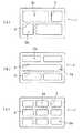
一方、「少なくとも一部がT字型構造のリブ」とは、少なくともリブ3の一部がT字型構造でありさえすれば良く、例えば図2に示すように、全体が十字型構造であってその一部に上記の如きT字型構造となる部分が含まれるようなリブをいうものとする。従って、発明でいう「少なくとも一部がT字型構造のリブ」には、図3(a)、(b)、(c)に示すような態様のものも含まれる。尚、これらの態様のものは、例えば図中斜線で示す部分がT字型構造となっている。
【0017】
上記の如きリブ3は、後述するような型内成形法によりラゲッジボックス1内に一体的に形成されるのが好ましいが、本発明ではリブ3をラゲッジボックス1とは別体に形成し、これを適宜手段によりラゲッジボックス1内に接合することもできる。
【0018】
更に本発明にあっては、例えば図4に示すように、リブ3aの所定位置に切欠溝7aを設けるとともに、これと相対するボックス1の内壁にも切欠溝7bを設け、両切欠溝7a、7bの間にリブ構成片3cを着脱自在に取り付けてリブ3を構成することもできる。
【0019】
リブ3を上記の如く構成すると、収納区画2a、2a、・・・の仕切り方をラゲッジボックス1に収納する収納物の形状や大きさに応じて適宜変更することができる。このような態様で本発明を実施する場合も、リブ3a及びリブ構成片3cから構成されるリブ3の全体又は少なくとも一部がT字型構造を有していれば良く、図4に示す態様では、例えば図中一点鎖線で囲む部分がT字型構造となっている。
【0020】
本発明においてボックス1内の収納部2に設ける全体又は少なくとも一部がT字型構造のリブ3は、収納部2を複数の収納区画2a、2a、・・・に仕切るだけでなく、本発明ラゲッジボックス1にエネルギー吸収性能を付与するための補強材としての役割をも兼ね備えている。
【0021】
本発明にあっては、ラゲッジボックス1を後述するような特定のポリプロピレン系樹脂発泡粒子成型体で構成し、ボックス1内の収納部2に設けるリブ3の形状を全体又は少なくとも一部がT字型構造のものとすることで、ラゲッジボックス1の軽量化を図るとともに、該ラゲッジボックス1のエネルギー吸収性能を優れたものとすることができる。
【0022】
ラゲッジボックス1への収納物の収納性や該ボックス1の軽量性を考慮するとともに、補強材としてのリブ3の作用を考慮してラゲッジボックス1のエネルギー吸収性能をより優れたものとするには、ラゲッジボックス1を平面から見たときの該ボックス1全体の面積に占めるリブ3の部分の面積(図2に示す態様のものを例にとれば、図中斜線で示した部分の面積)の割合が、3〜6%となるようにするのが好ましく、またリブ3の肉厚は6〜20mmであるのが好ましい。
【0023】
ここで図示する例にあっては、便宜上ラゲッジボックス1の形状を直方体状のものとしているが、本発明ラゲッジボックス1の形状は直方体状には限られず、トランクルームの構造や、ラゲッジボックス1を載置収納する位置に応じて、その形状を任意に変更することができる。
【0024】
即ち、一般に自動車のトランクルーム内はタイヤハウス等が突出していたり、スペアタイアが格納されている等、複雑な構造を有しており、またその構造は車種によってもまちまちである。本発明ラゲッジボックス1は自動車のトランクルーム内、例えば図7、8に示すようにトランクルーム9の底面部にトランクルーム9の幅方向にわたって載置収納されるが、ラゲッジボックス1をトランクルーム9内に載置収納する際の納まり具合が良くなるように、ラゲッジボックス1の形状はトランクルーム7の構造や、ラゲッジボックス1を載置収納する位置に応じて適宜選択することができる。但し、充分なエネルギー吸収性能を得るにはラゲッジボックス1の肉厚は6〜20mmであるのが好ましい。尚、図中8は自動車、10はスペアタイア、11はバンパー、12は座席シートを示している。
【0025】
本発明ラゲッジボックス1を上記の如く自動車のトランクルーム内に載置収納すれば、後方衝突の際の衝撃エネルギーが該ラゲッジボックス1に吸収され、これによって自動車の後部構造を強化することができる。尚、一部の市販車には前部にトランクルームが形成されているものもあるが、本発明ラゲッジボックス1はこのような自動車にも適用可能であり、この場合には自動車の前部構造が強化されることになる。
【0026】
本発明ラゲッジボックス1は、トランクルームの底面部の全面にわたって載置収納されるように構成されていても良く、トランクルームの底面部の一部(例えばスペアタイヤの上等)に載置収納されるように構成されていても良いが、ラゲッジボックス1をトランクルーム内に載置収納した際に、該ボックス1内に設けたリブ3のT字型構造を形成する部分のうち、ボックス1内の相対する内壁の一方の内壁から他方の内壁に延びる部分(図1に示す態様を例にとれば、リブ3aがこれに相当)が、自動車のバンパーと平行に位置するように構成するのが好ましい。本発明ラゲッジボックスをこのように構成すれば、リブ3が補強材として有効に作用し、ラゲッジボックス1のエネルギー吸収性能が最大限に発揮される。
【0027】
更に本発明ラゲッジボックス1は、該ボックス1と同一の素材からなる蓋体4と組み合わせ、蓋付きのラゲッジボックス1として用いるのが好ましい。この場合蓋体4はラゲッジボックス1の上面を覆う蓋となるだけでなく、ラゲッジボックス1のエネルギー吸収性能を向上させるための構造材ともなる。従って、このような蓋体4をラゲッジボックス1と組み合わせて用いる(即ちラゲッジボックス1の上面を蓋体4で覆い、これをトランクルーム内に載置収納する)ことで、ラゲッジボックス1のエネルギー吸収性能をより優れたものとすることができる。
【0028】
上記蓋体4の表面側及び/又は裏面側には補強用のリブ5を設けることができる。蓋体4に設けるリブの具体的な形態は特に問われず、例えば、図1に示す蓋体4のように不連続の格子状に設けても、図6(d)に示すような連続した格子状に設けても良く、或いは図6(e)に示すように十字状の独立したリブ5、5、・・・を散点状に設けたものであっても良い。
【0029】
このようなリブ5を蓋体4に設けることにより、ラゲッジボックス1をトランクルーム内に載置収納した状態での水平方向からの衝撃に対する強度を向上させることができるのみならず、垂直方向の荷重に対する強度を向上させることもでき、例えば蓋体4の上に荷物を載せたときや人が乗ったとき等に該蓋体4が撓むのを防ぐことができる。
【0030】
また蓋体4の裏面側にリブ5を設ける場合には、図1、5に示すように蓋体4に設けたリブ5が、ラゲッジボックス1に設けたリブ3や、ラゲッジボックス1の内壁と嵌合するようにして、蓋体4のズレ防止を図ることができる。尚、図5は図1に示す例において、ラゲッジボックス1の上面を蓋体4で覆った状態のもののV−V線断面図である。
【0031】
ラゲッジボックス1をトランクルーム内に載置収納するにあたり、該ボックス1に蓋体4を組み合わせて用いない場合は、従来からのトランクフロアー板材でラゲッジボックスの上面を覆うようにしても良い。また上記蓋体4はトランクルームフロアー板材を兼ねるように構成することもでき、蓋体4はラゲッジボックスよりも大きなものであっても良い。更にラゲッジボックス1や蓋体4には、装飾のために表面にシボ加工を施したり、不織布、フェルト、織布等の表皮材を積層したりすることができる。
【0032】
本発明ラゲッジボックス1は、例えば、ポリプロピレン系樹脂発泡粒子を成型用の金型内に充填した後に、該発泡粒子を蒸気等で加熱して粒子相互を融着せしめる、所謂型内成形法によって得られたポリプロピレン系樹脂発泡粒子成型体より構成される。尚、前述の蓋体4もラゲッジボックス1と同様のポリプロピレン系樹脂発泡粒子成型体から構成される。また、前述したようにリブ3をラゲッジボックス1と別体に形成する場合や、リブ構成片3cをラゲッジボックス1に着脱自在に取り付けるように構成する場合には、リブ3やリブ構成片3cは、ポリプロピレン系樹脂発泡体から構成するのが好ましい。
【0033】
ポリプロピレン系樹脂としては、ポリプロピレン、プロピレン−エチレン共重合体、プロピレン−ブテン共重合体、プロピレン−エチレン−ブテン共重合体等が例示されるが、これらの中でもポリプロピレン、プロピレン−ブテン共重合体が好ましい。これらのポリプロピレン系樹脂には、本発明の効果が損なわれない範囲で必要に応じて他の成分を共重合又はブレンドすることができる。またポリプロピレン系樹脂は架橋したものでも無架橋のものでも良いが、特に無架橋のものが好ましい。
【0034】
上記ポリプロピレン系樹脂発泡粒子は、例えば、密閉容器内でペレット状のプロピレン系樹脂粒子と発泡剤とを水等の分散媒に分散させ、該樹脂粒子が軟化する温度以上に加熱して樹脂粒子に発泡剤を含浸させた後、容器の一端を開放して樹脂粒子と分散媒とを容器内より低圧の雰囲気下(通常は大気圧下)に放出して樹脂粒子を発泡することにより得られる。
【0035】
本発明ラゲッジボックス1を構成するポリプロピレン系樹脂発泡粒子成型体は、このようなポリプロピレン系樹脂発泡粒子を必要に応じて空気、酸素、窒素、二酸化炭素等の無機ガス又はこれらの無機ガスとヘキサン、ヘプタン、1,1,1,2−テトラフルオロエタン、1,1−ジフルオロエタン等の揮発性発泡剤との混合ガスにより加圧処理して発泡粒子に0.3〜2.0kg/cm2(G)程度の内圧を付与した後、該発泡粒子を所望の形状の金型に充填し、2.5〜5.0kg/cm2(G)程度の蒸気により粒子を発泡膨張させ、粒子相互間を融着せしめる等により製造することができる。
【0036】
本発明にあっては上記成型体としては、密度ρが0.06〜0.30g/cm3、好ましくは0.075〜0.20g/cm3のものを用いる。密度ρが上記範囲を越えると重量大となりラゲッジボックス1の軽量化が図れなくなってしまう。一方、密度ρが上記範囲に満たないと充分なエネルギー吸収性能が得られず、所望のエネルギー吸収性能を確保しようとするとラゲッジボックス1の肉厚を厚くしなければならない。この結果ラゲッジボックス1の重量が大となり、結局ラゲッジボックス1の軽量化が図れない。また密度ρを上記範囲とすることにより、ラゲッジボックス1の遮音性も良好なものとなる。
【0037】
また上記成型体は密度ρと、該成型体の20℃における50%圧縮時のエネルギー吸収量E20(kg・cm/cm3)との間に、
E20/ρ ≧ 45 kg・cm/g ・・・・・・(1)
好ましくは、
E20/ρ ≧ 50 kg・cm/g
なる関係を有するのが好ましい。
【0038】
密度ρと20℃における50%圧縮時のエネルギー吸収量E20(kg・cm/cm3)との間に、上記関係が成り立たつポリプロピレン系樹脂発泡粒子成型体により本発明ラゲッジボックス1を構成することで、該ラゲッジボックス1の単位重量当たりのエネルギー吸収率を高くすることができ、より軽量で且つエネルギー吸収性能に優れたラゲッジボックス1となる。
【0039】
上記ポリプロピレン系樹脂発泡粒子成型体の20℃における50%圧縮時のエネルギー吸収量E20(kg・cm/cm3)は、該成型体から切り出した縦50mm、横50mm、厚さ25mmの試験片を用い、該試験片についてJIS Z0234 A法に準拠して圧縮試験を行なったときに得られる20℃における圧縮歪率−圧縮応力曲線において、圧縮歪率が50%となる点までの面積(図9中斜線部分)として求められる。尚、図9は密度0.127g/cm3のポリプロピレン系樹脂発泡粒子成型体の上記圧縮試験における圧縮歪率−圧縮応力曲線である。
【0040】
ポリプロピレン系樹脂発泡粒子成型体が、密度ρと20℃における50%圧縮時のエネルギー吸収量E20との間に前記(1)式なる関係を有するためには、プロピレン系樹脂発泡粒子として、例えば、球状に近く、平均粒径1.0〜7.0mm、好ましくは1.5〜3.5mm、平均気泡径100〜350μm、好ましくは120〜300μm、独立気泡率90%以上であるものを用い、前述したような型内成形法によって該成型体を製造すれば良い。
【0041】
【発明の効果】
以上説明したように本発明ラゲッジボックスは、密度0.06〜0.30g/cm3 のポリプロピレン系樹脂発泡粒子成型体からなり、該ボックス内の収納部が全体又は少なくとも一部がT字型構造のリブにより複数の収納区画に仕切られており、ポリプロピレン系樹脂発泡粒子成型体に、該成型体の密度ρと、該成型体の20℃における50%圧縮時のエネルギー吸収量E20(kg・cm/cm3)との間に、特定の関係を有するものを用いるため、ラゲッジボックスの単位重量当たりのエネルギー吸収率を高くすることができ、充分なエネルギー吸収性能を有するものであるから、該ラゲッジボックスを自動車のトランクルーム内に載置収納すれば、自動車の後部構造の強化を図ることができる。しかも上記構成の本発明ラゲッジボックスは軽量であるため、トランクルーム内からの取り出し等が容易であり、取扱いが便利のものである上、燃費の低下を招くこともない。また走行時の振動に共鳴してラゲッジボックスから異音が発生することもなく遮音性にも優れている。
【図面の簡単な説明】
【図1】本発明ラゲッジボックスの一例を示す斜視図である。
【図2】本発明ラゲッジボックスの他の一例を示す斜視図である。
【図3】本発明ラゲッジボックスの他の一例を示す平面図である。
【図4】本発明ラゲッジボックスの他の一例を示す斜視図である。
【図5】図1に示す一例において、ラゲッジボックスの上面を蓋体で覆った状態のもののV−V線断面図である。
【図6】蓋体の一例を示す平面図である。
【図7】本発明ラゲッジボックスをトランクルーム内に載置収納した状態を示す概略図である。
【図8】本発明ラゲッジボックスをトランクルーム内に載置収納した状態を示す概略図である。
【図9】ポリプロピレン系樹脂発泡粒子成型体から切り出した試験片の圧縮試験における圧縮歪率−圧縮応力曲線である。
【符号の説明】
1 ラゲッジボックス
2 収納部
2a 収納区画
3 リブ
8 自動車
9 トランクルーム[0001]
BACKGROUND OF THE INVENTION
The present invention relates to a luggage box placed and stored in a trunk room of an automobile.
[0002]
[Prior art and problems to be solved by the invention]
In recent years, the safety design of the car body structure has become more important with the improvement of the performance of automobiles. Especially, the impact energy at the time of a collision accident is absorbed to prevent the deformation of the car body frame, so that the occupant in the event of a collision. The body structure that can maintain the living space is attracting attention.
[0003]
By the way, a general automobile has an engine room formed in a front portion, and an engine is mounted therein. For this reason, in the case of a frontal collision, a certain amount of energy absorption effect can be expected, and the vehicle body structure of the occupant living space is relatively rarely deformed at the time of the collision.
[0004]
On the other hand, in the case of a rear collision, the trunk room formed in the rear part of the automobile has a hollow structure, so the energy absorption effect that can be obtained in the case of a front collision cannot be expected. The vehicle body structure in the passenger space is often deformed. In particular, in a car called a 1BOX car or 2BOX car, there is no clear partition between the passenger's living space and the trunk room, and it is structurally difficult to make the rear structure resistant to impact. .
[0005]
Here, looking at the internal structure of the trunk room, the bottom part of the trunk floor is usually a trunk floor board made of a core material such as wooden plywood, insulation board, cardboard, synthetic resin board, FRP board, etc., coated with a surface material such as nonwoven fabric. It is laid. Also, some commercial vehicles have a luggage box for storing tools placed and stored in the trunk room.
[0006]
However, even if a plate material such as that described above is laid on the bottom surface of the trunk room, it is not possible to expect sufficient energy absorption performance to absorb impact energy at the time of collision.
[0007]
On the other hand, when the luggage box is placed and stored in the trunk room, the luggage box has a box structure, so depending on the position where the luggage box is placed and stored, the energy absorption effect cannot be expected. Is an injection molded product or an injection blow molded product, and in order to sufficiently absorb the impact at the time of collision, it is necessary to increase its rigidity by increasing the thickness. For this reason, if the luggage box has energy absorption performance, the weight will inevitably increase, and the increase in the weight of the luggage box will not only be inconvenient to handle, but it will also lead to an increase in the weight of the vehicle body, leading to a reduction in fuel consumption. There is also a problem.
[0008]
In addition, when a luggage box is placed and stored in the trunk room, abnormal noise is generated from the luggage box in resonance with vibration during traveling, or the generated abnormal noise is amplified as a combo sound in the luggage box. There is a problem like this, and it is necessary to take measures for this. It is also possible to suppress vibration of the luggage box by placing steel plate material on the luggage box, putting lead in the lid of the luggage box, and further, etc., so that no abnormal noise is generated. However, an increase in the weight of the luggage box is inevitable when this is dealt with.
[0009]
In view of the above problems, the inventors of the present invention have attempted to reduce the weight of the luggage box placed and stored in the trunk room in order to strengthen the vehicle body structure of the automobile, and have sufficient energy absorption performance while being lightweight. As a result of intensive studies to provide a luggage box, the present invention has been completed.
[0010]
[Means for Solving the Problems]
That is, the luggage box of the present invention is a luggage box placed and stored in a trunk room of an automobile, and the luggage box is formed of a molded polypropylene resin foam particle having a density of 0.06 to 0.30 g / cm3. The storage part in the box is entirely or at least partially partitioned into a plurality of storage compartments by ribs having a T-shaped structure,and the density ρ (g / cm3 of thepolypropylene resin foamed particle molded body)) And energy absorption amount E20(kg · cm / cm3) at 50% compression of the molded body at 20 ° C.) And the following formula (1).
[0011]
(Equation 2)
E20 / ρ ≧ 45 (kg · cm / g) (1)
[0012]
Further, in the present invention, the polypropylene resin foamed particle molded body is formed by in-mold molding foamed particles having an average particle diameter of 1.0 to 7.0 mm, an average cell diameter of 100 to 350 μm, and a closed cell ratio of 90% or more. It is preferable that
[0013]
DETAILED DESCRIPTION OF THE INVENTION
Hereinafter, the luggage box of the present invention will be described with reference to the drawings. FIG. 1 is a perspective view showing an example of the luggage box of the present invention. FIG. 2 is a perspective view showing another example of the luggage box of the present invention, and FIG. 3 is a plan view showing still another example.
[0014]
In the
[0015]
In the present invention, "the rib having a T-shaped structure as a whole" means a
[0016]
On the other hand, “at least a part of the rib having a T-shaped structure” is sufficient if at least a part of the
[0017]
The
[0018]
Further, in the present invention, for example, as shown in FIG. 4, a
[0019]
If the
[0020]
In the present invention, the
[0021]
In the present invention, the
[0022]
To improve the energy absorption performance of the
[0023]
In the example shown here, the shape of the
[0024]
In other words, in general, a trunk house of an automobile has a complicated structure such as a protruding tire house or a spare tire stored therein, and the structure varies depending on the vehicle type. The
[0025]
When the
[0026]
The
[0027]
Furthermore, the
[0028]
Reinforcing
[0029]
By providing such a
[0030]
When the
[0031]
When the
[0032]
The
[0033]
Examples of the polypropylene resin include polypropylene, propylene-ethylene copolymer, propylene-butene copolymer, propylene-ethylene-butene copolymer, and among these, polypropylene and propylene-butene copolymer are preferable. . These polypropylene resins can be copolymerized or blended with other components as necessary within the range in which the effects of the present invention are not impaired. The polypropylene resin may be crosslinked or non-crosslinked, but is preferably non-crosslinked.
[0034]
The polypropylene-based resin expanded particles are, for example, dispersed in a sealed container with pellet-shaped propylene-based resin particles and a foaming agent in a dispersion medium such as water, and heated to a temperature higher than the temperature at which the resin particles soften. After impregnating the foaming agent, one end of the container is opened, and the resin particles and the dispersion medium are released from the inside of the container into a low-pressure atmosphere (usually under atmospheric pressure) to foam the resin particles.
[0035]
The polypropylene resin foamed particle molded body constituting the
[0036]
In the present invention, the molded body has a density ρ of 0.06 to 0.30 g / cm3 , preferably 0.075 to 0.20 g / cm3 . If the density ρ exceeds the above range, the weight is increased and the
[0037]
The molded body has a density ρ between an energy absorption amount E20 (kg · cm / cm3 ) of 50% compression at 20 ° C. of the molded body,
E20 / ρ ≧ 45 kg · cm / g (1)
Preferably,
E20 / ρ ≧ 50 kg · cm / g
It is preferable to have the relationship
[0038]
The
[0039]
The polypropylene resin foamed molded article has an energy absorption amount E20 (kg · cm / cm3 ) at 50% compression at 20 ° C. of 50 mm long, 50 mm wide and 25 mm thick test pieces cut out from the molded body. In the compressive strain rate-compressive stress curve at 20 ° C. obtained when a compressive test is performed on the test piece according to JIS Z0234 A method, the area up to the point where the compressive strain rate becomes 50% (see FIG. 9). FIG. 9 is a compressive strain rate-compressive stress curve in the above compression test of a molded polypropylene resin foam particle having a density of 0.127 g / cm3 .
[0040]
In order for the polypropylene-based resin expanded particle molded body to have the relationship represented by the above formula (1) between the density ρ and the energy absorption amount E20 at the time of 50% compression at 20 ° C., as the propylene-based resin expanded particles, for example, , Which is nearly spherical, has an average particle diameter of 1.0 to 7.0 mm, preferably 1.5 to 3.5 mm, an average bubble diameter of 100 to 350 μm, preferably 120 to 300 μm, and a closed cell ratio of 90% or more. The molded body may be manufactured by the in-mold molding method as described above.
[0041]
【The invention's effect】
As described above, the luggage box of the present invention is made of a molded polypropylene resin foam particle having a density of 0.06 to 0.30 g / cm3 , and the storage part in the box is entirely or at least partly a T-shaped structure. The ribs are divided into a plurality of storage compartments.The density ρ of the molded body and the energy absorption amount E20when the molded body is compressed at 50% at 20 ° C.(kg · cm / cm3) Is used, the energy absorption rate per unit weight of the luggage box can be increased , and the luggage box has sufficient energy absorption performance. If the vehicle is placed and stored in the trunk room, the rear structure of the automobile can be strengthened. Moreover, since the luggage box of the present invention having the above structure is lightweight, it can be easily taken out from the trunk room, is easy to handle, and does not cause a reduction in fuel consumption. In addition, there is no noise from the luggage box in resonance with vibration during travel, and the sound insulation is excellent.
[Brief description of the drawings]
FIG. 1 is a perspective view showing an example of a luggage box according to the present invention.
FIG. 2 is a perspective view showing another example of the luggage box of the present invention.
FIG. 3 is a plan view showing another example of the luggage box of the present invention.
FIG. 4 is a perspective view showing another example of the luggage box of the present invention.
5 is a cross-sectional view taken along the line V-V of the luggage box with the upper surface covered with a lid in the example shown in FIG. 1;
FIG. 6 is a plan view showing an example of a lid.
FIG. 7 is a schematic view showing a state in which the luggage box of the present invention is placed and stored in a trunk room.
FIG. 8 is a schematic view showing a state in which the luggage box of the present invention is placed and stored in a trunk room.
FIG. 9 is a compressive strain-compression stress curve in a compression test of a test piece cut out from a polypropylene resin foamed particle molded body.
[Explanation of symbols]
DESCRIPTION OF
Claims (2)
Translated fromJapanese(数1)
E20/ρ ≧ 45 (kg・cm/g) ・・・・・・(1)A luggage box placed and stored in a trunk room of an automobile, wherein the luggage box is formed of a molded polypropylene resin foam particle having a density of 0.06 to 0.30 g / cm3 , and the storage portion in the box is entirely Alternatively, at least a part is partitioned into a plurality of storage compartments by ribs having a T-shaped structure,and the density ρ (g / cm3 of thepolypropylene resin foamed particle molded body)) And energy absorption amount E20(kg · cm / cm3) at 50% compression of the molded body at 20 ° C.The luggage box has a relationship represented by the following expression (1).
(Equation1)
E20/ ρ ≧ 45 (kg · cm / g) (1)
Priority Applications (1)
| Application Number | Priority Date | Filing Date | Title |
|---|---|---|---|
| JP20298496AJP3759997B2 (en) | 1996-07-12 | 1996-07-12 | Luggage box |
Applications Claiming Priority (1)
| Application Number | Priority Date | Filing Date | Title |
|---|---|---|---|
| JP20298496AJP3759997B2 (en) | 1996-07-12 | 1996-07-12 | Luggage box |
Publications (2)
| Publication Number | Publication Date |
|---|---|
| JPH1029466A JPH1029466A (en) | 1998-02-03 |
| JP3759997B2true JP3759997B2 (en) | 2006-03-29 |
Family
ID=16466414
Family Applications (1)
| Application Number | Title | Priority Date | Filing Date |
|---|---|---|---|
| JP20298496AExpired - Fee RelatedJP3759997B2 (en) | 1996-07-12 | 1996-07-12 | Luggage box |
Country Status (1)
| Country | Link |
|---|---|
| JP (1) | JP3759997B2 (en) |
Cited By (1)
| Publication number | Priority date | Publication date | Assignee | Title |
|---|---|---|---|---|
| JP2011012136A (en)* | 2009-06-30 | 2011-01-20 | Sekisui Plastics Co Ltd | Expansion molding and luggage box for vehicle comprising expansion molding |
Families Citing this family (6)
| Publication number | Priority date | Publication date | Assignee | Title |
|---|---|---|---|---|
| JP4297717B2 (en)* | 2003-03-31 | 2009-07-15 | キョーラク株式会社 | Luggage box |
| EP1787863A1 (en) | 2004-07-28 | 2007-05-23 | Kaneka Corporation | Luggage box for automobile |
| JPWO2006043703A1 (en) | 2004-10-19 | 2008-05-22 | キョーラク株式会社 | Blow molded product with skin and method for producing the same |
| JP5032517B2 (en)* | 2009-02-09 | 2012-09-26 | 本田技研工業株式会社 | Car luggage compartment structure |
| PL393027A1 (en)* | 2010-11-23 | 2012-06-04 | Langsteiner Alicja Fa Langsteiner | Set of containers and method for strengthening the car's body |
| JP6253427B2 (en)* | 2014-01-31 | 2017-12-27 | 株式会社ジェイエスピー | Car article storage member |
- 1996
- 1996-07-12JPJP20298496Apatent/JP3759997B2/ennot_activeExpired - Fee Related
Cited By (1)
| Publication number | Priority date | Publication date | Assignee | Title |
|---|---|---|---|---|
| JP2011012136A (en)* | 2009-06-30 | 2011-01-20 | Sekisui Plastics Co Ltd | Expansion molding and luggage box for vehicle comprising expansion molding |
Also Published As
| Publication number | Publication date |
|---|---|
| JPH1029466A (en) | 1998-02-03 |
Similar Documents
| Publication | Publication Date | Title |
|---|---|---|
| US7775584B2 (en) | Impact absorbing armrest for a motor vehicle | |
| US10429006B2 (en) | Cellular structures with twelve-cornered cells | |
| US10220881B2 (en) | Cellular structures with fourteen-cornered cells | |
| US10948000B2 (en) | Cellular structures with twelve-cornered cells | |
| US10473177B2 (en) | Cellular structures with sixteen-cornered cells | |
| US10704638B2 (en) | Cellular structures with twelve-cornered cells | |
| US20180099475A1 (en) | Cellular structures with twelve-cornered cells | |
| US6561562B1 (en) | Motor vehicle with heat insulation | |
| US6652034B1 (en) | Upholstery support | |
| US8157322B2 (en) | Seat back assembly with low density frame | |
| US10391911B2 (en) | Composite seat core material and vehicular seat element using the composite seat core material | |
| US7182382B2 (en) | Resin-made floor panel structure | |
| JP3759997B2 (en) | Luggage box | |
| JP2003127796A (en) | Shock absorbing floor spacer for automobile | |
| JPH11222155A (en) | Car body structure having at least one lateral connecting member | |
| US8414053B2 (en) | Seat back assembly with integral reinforcement structure | |
| JP2009073401A (en) | Luggage floor trim | |
| JP4059655B2 (en) | Automotive floor spacer and manufacturing method thereof | |
| JPH0716867A (en) | Shock absorbing structure of interior member for automobile | |
| JP4167932B2 (en) | Resin floor panel structure | |
| US4413838A (en) | Passenger restraint system | |
| JP4021928B2 (en) | Shock absorber for automobile floor spacer | |
| CN118900793A (en) | Removable seat assembly for a vehicle cargo compartment | |
| JPS642845Y2 (en) | ||
| JP2021098464A (en) | Shock absorbing structure |
Legal Events
| Date | Code | Title | Description |
|---|---|---|---|
| A977 | Report on retrieval | Free format text:JAPANESE INTERMEDIATE CODE: A971007 Effective date:20050615 | |
| A131 | Notification of reasons for refusal | Free format text:JAPANESE INTERMEDIATE CODE: A131 Effective date:20050622 | |
| A521 | Written amendment | Free format text:JAPANESE INTERMEDIATE CODE: A523 Effective date:20050721 | |
| A131 | Notification of reasons for refusal | Free format text:JAPANESE INTERMEDIATE CODE: A131 Effective date:20050907 | |
| A521 | Written amendment | Free format text:JAPANESE INTERMEDIATE CODE: A523 Effective date:20051003 | |
| TRDD | Decision of grant or rejection written | ||
| A01 | Written decision to grant a patent or to grant a registration (utility model) | Free format text:JAPANESE INTERMEDIATE CODE: A01 Effective date:20051221 | |
| A61 | First payment of annual fees (during grant procedure) | Free format text:JAPANESE INTERMEDIATE CODE: A61 Effective date:20060106 | |
| R150 | Certificate of patent (=grant) or registration of utility model | Free format text:JAPANESE INTERMEDIATE CODE: R150 | |
| FPAY | Renewal fee payment (event date is renewal date of database) | Free format text:PAYMENT UNTIL: 20090113 Year of fee payment:3 | |
| FPAY | Renewal fee payment (event date is renewal date of database) | Free format text:PAYMENT UNTIL: 20100113 Year of fee payment:4 | |
| FPAY | Renewal fee payment (event date is renewal date of database) | Free format text:PAYMENT UNTIL: 20110113 Year of fee payment:5 | |
| FPAY | Renewal fee payment (event date is renewal date of database) | Free format text:PAYMENT UNTIL: 20120113 Year of fee payment:6 | |
| FPAY | Renewal fee payment (event date is renewal date of database) | Free format text:PAYMENT UNTIL: 20130113 Year of fee payment:7 | |
| FPAY | Renewal fee payment (event date is renewal date of database) | Free format text:PAYMENT UNTIL: 20130113 Year of fee payment:7 | |
| FPAY | Renewal fee payment (event date is renewal date of database) | Free format text:PAYMENT UNTIL: 20140113 Year of fee payment:8 | |
| R250 | Receipt of annual fees | Free format text:JAPANESE INTERMEDIATE CODE: R250 | |
| R250 | Receipt of annual fees | Free format text:JAPANESE INTERMEDIATE CODE: R250 | |
| LAPS | Cancellation because of no payment of annual fees |