JP3759872B2 - Cell module - Google Patents
Cell moduleDownload PDFInfo
- Publication number
- JP3759872B2 JP3759872B2JP2000383402AJP2000383402AJP3759872B2JP 3759872 B2JP3759872 B2JP 3759872B2JP 2000383402 AJP2000383402 AJP 2000383402AJP 2000383402 AJP2000383402 AJP 2000383402AJP 3759872 B2JP3759872 B2JP 3759872B2
- Authority
- JP
- Japan
- Prior art keywords
- terminal
- cell
- bus bar
- connection
- bar plate
- Prior art date
- Legal status (The legal status is an assumption and is not a legal conclusion. Google has not performed a legal analysis and makes no representation as to the accuracy of the status listed.)
- Expired - Fee Related
Links
Images


Classifications
- H—ELECTRICITY
- H01—ELECTRIC ELEMENTS
- H01G—CAPACITORS; CAPACITORS, RECTIFIERS, DETECTORS, SWITCHING DEVICES, LIGHT-SENSITIVE OR TEMPERATURE-SENSITIVE DEVICES OF THE ELECTROLYTIC TYPE
- H01G9/00—Electrolytic capacitors, rectifiers, detectors, switching devices, light-sensitive or temperature-sensitive devices; Processes of their manufacture
- H01G9/26—Structural combinations of electrolytic capacitors, rectifiers, detectors, switching devices, light-sensitive or temperature-sensitive devices with each other
- H—ELECTRICITY
- H01—ELECTRIC ELEMENTS
- H01M—PROCESSES OR MEANS, e.g. BATTERIES, FOR THE DIRECT CONVERSION OF CHEMICAL ENERGY INTO ELECTRICAL ENERGY
- H01M10/00—Secondary cells; Manufacture thereof
- H01M10/04—Construction or manufacture in general
- H01M10/0422—Cells or battery with cylindrical casing
- H—ELECTRICITY
- H01—ELECTRIC ELEMENTS
- H01M—PROCESSES OR MEANS, e.g. BATTERIES, FOR THE DIRECT CONVERSION OF CHEMICAL ENERGY INTO ELECTRICAL ENERGY
- H01M50/00—Constructional details or processes of manufacture of the non-active parts of electrochemical cells other than fuel cells, e.g. hybrid cells
- H01M50/50—Current conducting connections for cells or batteries
- H01M50/543—Terminals
- H01M50/547—Terminals characterised by the disposition of the terminals on the cells
- H01M50/55—Terminals characterised by the disposition of the terminals on the cells on the same side of the cell
- H—ELECTRICITY
- H01—ELECTRIC ELEMENTS
- H01M—PROCESSES OR MEANS, e.g. BATTERIES, FOR THE DIRECT CONVERSION OF CHEMICAL ENERGY INTO ELECTRICAL ENERGY
- H01M50/00—Constructional details or processes of manufacture of the non-active parts of electrochemical cells other than fuel cells, e.g. hybrid cells
- H01M50/50—Current conducting connections for cells or batteries
- H01M50/543—Terminals
- H01M50/552—Terminals characterised by their shape
- H01M50/559—Terminals adapted for cells having curved cross-section, e.g. round, elliptic or button cells
- H—ELECTRICITY
- H01—ELECTRIC ELEMENTS
- H01M—PROCESSES OR MEANS, e.g. BATTERIES, FOR THE DIRECT CONVERSION OF CHEMICAL ENERGY INTO ELECTRICAL ENERGY
- H01M10/00—Secondary cells; Manufacture thereof
- H01M10/05—Accumulators with non-aqueous electrolyte
- H01M10/052—Li-accumulators
- H—ELECTRICITY
- H01—ELECTRIC ELEMENTS
- H01M—PROCESSES OR MEANS, e.g. BATTERIES, FOR THE DIRECT CONVERSION OF CHEMICAL ENERGY INTO ELECTRICAL ENERGY
- H01M10/00—Secondary cells; Manufacture thereof
- H01M10/34—Gastight accumulators
- H01M10/345—Gastight metal hydride accumulators
- H—ELECTRICITY
- H01—ELECTRIC ELEMENTS
- H01M—PROCESSES OR MEANS, e.g. BATTERIES, FOR THE DIRECT CONVERSION OF CHEMICAL ENERGY INTO ELECTRICAL ENERGY
- H01M6/00—Primary cells; Manufacture thereof
- H01M6/42—Grouping of primary cells into batteries
- Y—GENERAL TAGGING OF NEW TECHNOLOGICAL DEVELOPMENTS; GENERAL TAGGING OF CROSS-SECTIONAL TECHNOLOGIES SPANNING OVER SEVERAL SECTIONS OF THE IPC; TECHNICAL SUBJECTS COVERED BY FORMER USPC CROSS-REFERENCE ART COLLECTIONS [XRACs] AND DIGESTS
- Y02—TECHNOLOGIES OR APPLICATIONS FOR MITIGATION OR ADAPTATION AGAINST CLIMATE CHANGE
- Y02E—REDUCTION OF GREENHOUSE GAS [GHG] EMISSIONS, RELATED TO ENERGY GENERATION, TRANSMISSION OR DISTRIBUTION
- Y02E60/00—Enabling technologies; Technologies with a potential or indirect contribution to GHG emissions mitigation
- Y02E60/10—Energy storage using batteries
- Y—GENERAL TAGGING OF NEW TECHNOLOGICAL DEVELOPMENTS; GENERAL TAGGING OF CROSS-SECTIONAL TECHNOLOGIES SPANNING OVER SEVERAL SECTIONS OF THE IPC; TECHNICAL SUBJECTS COVERED BY FORMER USPC CROSS-REFERENCE ART COLLECTIONS [XRACs] AND DIGESTS
- Y02—TECHNOLOGIES OR APPLICATIONS FOR MITIGATION OR ADAPTATION AGAINST CLIMATE CHANGE
- Y02P—CLIMATE CHANGE MITIGATION TECHNOLOGIES IN THE PRODUCTION OR PROCESSING OF GOODS
- Y02P70/00—Climate change mitigation technologies in the production process for final industrial or consumer products
- Y02P70/50—Manufacturing or production processes characterised by the final manufactured product
- Y—GENERAL TAGGING OF NEW TECHNOLOGICAL DEVELOPMENTS; GENERAL TAGGING OF CROSS-SECTIONAL TECHNOLOGIES SPANNING OVER SEVERAL SECTIONS OF THE IPC; TECHNICAL SUBJECTS COVERED BY FORMER USPC CROSS-REFERENCE ART COLLECTIONS [XRACs] AND DIGESTS
- Y02—TECHNOLOGIES OR APPLICATIONS FOR MITIGATION OR ADAPTATION AGAINST CLIMATE CHANGE
- Y02T—CLIMATE CHANGE MITIGATION TECHNOLOGIES RELATED TO TRANSPORTATION
- Y02T10/00—Road transport of goods or passengers
- Y02T10/60—Other road transportation technologies with climate change mitigation effect
- Y02T10/70—Energy storage systems for electromobility, e.g. batteries
Landscapes
- Engineering & Computer Science (AREA)
- Chemical & Material Sciences (AREA)
- Chemical Kinetics & Catalysis (AREA)
- Electrochemistry (AREA)
- General Chemical & Material Sciences (AREA)
- Power Engineering (AREA)
- Microelectronics & Electronic Packaging (AREA)
- Manufacturing & Machinery (AREA)
- Connection Of Batteries Or Terminals (AREA)
- Fixed Capacitors And Capacitor Manufacturing Machines (AREA)
- Battery Mounting, Suspending (AREA)
Description
Translated fromJapanese【0001】
【発明の属する技術分野】
本発明は、電気自動車やハイブリッド電気自動車等に駆動電源として搭載されるセルモジュールの構造に関する。本発明で言うセルは、ニッケル水素やリチウム電池等の単電池や、電気二重層コンデンサ(ウルトラキャパシタ)等のエネルギーストレージ素子等の蓄電素子全般を全て含む。
【0002】
【従来の技術】
複数のセルを直列接続したセルモジュールとしては、例えば、一端に正極端子および負極端子が並べて設けられた円筒型もしくは直方体型の複数のセルを並列に設置し、隣り合うセルの正極端子と負極端子とをバスバーを介して直列に接続して連結したものが挙げられる。このようなセルモジュールを組み立てる際の端子へのバスバーの取り付けは、ボルト結合あるいはナット結合によっているものが一般的であった。
【0003】
図18は、従来のセルモジュールを構成するセル100およびバスバー110の一例を示している。この場合、円筒型のセル100の一端面に正極端子101と負極端子102が並んで突設されており、バスバー110における互いに絶縁された正極側バスバー111と負極側バスバー112に通したボルト120,120を、正極端子101と負極端子102にそれぞれねじ込んで締結し、直列接続する構成となっている。
【0004】
【発明が解決しようとする課題】
図18に示した接続形態を基本として複数のセルを直列接続する従来のセルモジュール構造においては、バスバーによる端子どうしの接続は、端子に対するバスバーの位置決めに次いでボルトの締結を行うといった作業を繰り返すことになるので、接続作業に手間がかかることになる。しかも、ボルトを締結するには、締結用の工具を操作するための広い作業空間を要することに加え、締結用工具による短絡が生じない配慮が必要であることから、接続作業の煩雑さが助長されていた。
【0005】
また、接続抵抗を低減させるためには、端子とバスバーとの接続状態を強固にする必要があるものの、振動や温度変化に伴う変形等に起因して接続部分にかかる荷重が増大して接続状態に悪影響を及ぼすおそれがあった。そこで、保持部材によってセルを保持し、接続部への負荷を軽減させているが、これは、部品点数の増加と構造の複雑化を招く。
【0006】
また、一端に正極端子および負極端子が並べて設けられたセルにおいては、セルおよびセルモジュール全体の占有面積が大きくなりがちであり、限られた空間を有効に活用することが求められる車両においては、不利な構造である。
【0007】
さらに、正極端子と負極端子の形状を変えて、正極端子どうし、あるいは負極端子を接続させてしまう誤組を防止しているものの、端子は突起であることに変わりない場合が多いので、誤組を完全に防止することができなかった。その上、端子が突起であることから、取り扱いを誤って端子を損傷させて十分な電気接触が果たせなくなったり、短絡させたりしてしまうおそれもあった。
【0008】
したがって本発明は、以下の事項を満足するセルモジュールを提供することを目的としている。
〔1〕セルの接続を容易とし、かつ、低抵抗化が図られる。
〔2〕セルの緻密なレイアウトを可能とし、空間の有効利用が図られる。
〔3〕誤組、端子の損傷および短絡を防止することができる。
【0009】
【課題を解決するための手段】
本発明は、筒状のセルと、セルを接続するための端子接続部を有するバスバープレートとを備えたセルモジュールであって、セルの一端に、互いに極性の異なる内側セル端子と外側セル端子とが同軸的に配設され、一方、バスバープレートの端子接続部には、セルの内側セル端子および外側セル端子に対応した内側接続端子および外側接続端子が同軸的に配設されており、セルとバスパープレートとを相対的に回転させることなく軸方向に接近させることによって、セルの外側セル端子と端子接続部の外側接続端子とが嵌合するとともに、内側セル端子と内側接続端子とが嵌合する接続形態により、セルの内側セル端子と外側セル端子とがバスバープレートの端子接続部に接続されていることを特徴とする。本発明では、セルの各セル端子とバスバープレートの端子接続部における各接続端子との嵌合部を、溶着または接着によって保持することを含む。
【0010】
本発明のセルの端子(正・負の端子)は、内側セル端子と外側セル端子として一端に同軸的に配設されており、バスバープレートの端子接続部には、セルの各端子に対応する内側接続端子と外側接続端子が配設されている。そして、セル側の各端子を端子接続部側の各端子にそれぞれ当接させてセルモジュールが構成される。正負の端子の同軸的な配置によって端子接続部へのセルの接続が容易となり、しかも、電力の伝達距離もきわめて短くなるので低抵抗化が図られる。また、セルおよびセルモジュール全体の占有面積が小さくなるので限られた空間を有効に活用することができ、複数を接続する場合に緻密なレイアウトが可能となる。さらに、極性を見極めてセルを端子接続部に接続する必要性から解放される点でも接続作業が容易となり、しかも同極どうしの誤組およびそれに伴う短絡が防止される。
【0011】
次に、上記本発明のより具体的な手段としては、セルの一端に同軸的に配設した内側および外側セル端子のうち、少なくとも外側セル端子が筒状に形成されているとともに、その内周面または外周面にネジ部が形成されており、一方、バスバープレートの端子接続部には、セルの内側セル端子および外側セル端子に対応した内側接続端子および外側接続端子が同軸的に配設され、かつ、外側接続端子には、外側セル端子のネジ部が螺合するネジ部が形成されており、その外側セル端子のネジ部が、端子接続部の外側接続端子のネジ部に螺合されるに伴い、内側セル端子と内側接続端子とが当接する接続形態により、セルの内側セル端子と外側セル端子とがバスバープレートの端子接続部を介して接続されていることを特徴としている。
【0012】
この発明によれば、セルを軸回りに回転させて、セルの外側セル端子に設けたネジ部を、端子接続部の外側接続端子に設けたネジ部に螺合させて締結する。これにより、セルの外側セル端子と端子接続部の外側接続端子とがネジ結合により接触し、一方、セルのねじ込み作用により、セルの内側セル端子が端子接続部の内側接続端子に突き当たって接触する。この接続形態により、セルの内側セル端子および外側セル端子は、バスバープレートの端子接続部に接続される。
【0013】
さらに本発明の別の具体的手段としては、セルの一端に同軸的に配設した内側および外側セル端子のうち、内側セル端子は円柱状であって、その外周面にネジ部が形成されており、一方、バスバープレートの端子接続部には、セルの内側セル端子および外側セル端子に対応した内側接続端子および外側接続端子が同軸的に配設され、かつ、内側接続端子には、内側セル端子のネジ部が螺合するネジ部が形成されており、その内側セル端子のネジ部が、端子接続部の内側接続端子のネジ部に螺合されるに伴い、外側セル端子と外側接続端子とが当接する接続形態により、セルの内側セル端子と外側セル端子とがバスバープレートの端子接続部を介して接続されていることを特徴とする。
【0014】
この発明は、内側セル端子側にネジ部を形成しており、セルを軸回りに回転させて、セルの内側セル端子のネジ部を端子接続部の内側接続端子のネジ部に螺合させて締結する。これにより、セルの内側セル端子と端子接続部の内側接続端子がネジ結合により接触し、一方、セルのねじ込み作用により、セルの外側セル端子がバスバープレートの外側接続端子に突き当たって接触する。この接続形態により、セルの内側セル端子および外側セル端子は、バスバープレートの端子接続部に接続される。
【0015】
上記のような端子どうしのネジ結合による接続形態によれば、端子どうしの接触面圧を十分に確保することができ、かつ、電力の伝達距離もきわめて短くなるので、大幅な低抵抗化が図られる。また、ねじの締結によってセル側の端子と端子接続部側の端子との接続状態の剛性を高くすることができるので、その接続状態が強固に保持されて低抵抗化が促進される。特に、セルのねじ締結部を外側セル端子に設けた場合、内側セル端子に設けた場合と比べると接続状態における剛性がより高く、上記効果をより一層得ることができる。
【0016】
また、セルをバスバープレートの端子接続部にねじ込むだけでセルを端子接続部に接続させる構造なので、ボルトやナット等の締結部材および締結用工具が不要である。このため、接続作業をきわめて容易に行うことができ、その作業空間も狭くて済むことに加え、セルおよびセルモジュール全体の占有面積が小さく、限られた空間を有効に活用することができる。さらに、セルの端子の極性を見極めてバスバープレートに接続する必要性から解放される点でも接続作業が容易となり、しかも同極どうしの誤組およびそれに伴う短絡が防止される。
【0017】
本発明は、セルをバスバープレートの端子接続部に接続する構造を基本としているが、複数のセルを連結したセルモジュールを構築する上できわめて好適である。その構造として、複数の端子接続部がバスバープレートの片面に直列状態に設けられ、これら端子接続部に複数のセルが上記の接続形態で接続されていることを特徴とする。また、複数の端子接続部がバスバープレートの両面に直列状態に設けられ、これら端子接続部に複数のセルが上記の接続形態で接続されていることを特徴とする。
【0018】
このように複数のセルを直列接続させれば、隣り合うセル間の間隔を極力小さくすることによってセルの緻密なレイアウトが可能となり、セルモジュール全体のコンパクト化と、空間の有効利用が図られる。
【0019】
さて、本発明では、以下の形態を採用することができる。
▲1▼セルの外側セル端子を筒状とし、その内部に内側セル端子を配し、外側セル端子の高さを内側セル端子の高さよりも高くする。これによると、内側セル端子は外側セル端子に保護された状態となる。この形態を、外側セル端子の内周面にネジ部を形成する発明に適用すれば、実質的な電力受け渡し部分である内側セル端子の端面および外側セル端子のネジ部を損傷させる可能性が少なくなる。また、内側セル端子の外周面にネジ部を形成する発明に適用すれば、実質的な電力受け渡し部分である外側セル端子の端面および内側セル端子のネジ部を損傷させる可能性が少なくなる。いずれの場合も、十分な電気接触が果たせなくなる不具合が解消されるとともに、両端子を短絡させる可能性も少なくなる。
【0020】
▲2▼上記▲1▼の形態とは反対に、内側セル端子の高さを外側セル端子の高さよりも高くして突出させる。
【0021】
▲3▼セルの外側セル端子と内側セル端子との間に絶縁材を介在させて短絡防止を確実なものとし、さらに、この絶縁材を、外側セル端子および内側セル端子よりも高くして突出させる。この場合、絶縁材により外側セル端子および内側セル端子を保護することができる。
【0022】
▲4▼ネジ部どうしによる接続ではなく当接による端子どうしの接続部分に、導電性の弾性部材を挟み、この弾性部材を介してそれら端子どうしを電気的に接続させる。弾性部材としては、ヘリサート等が好適に用いられる。
【0023】
▲5▼セルにおける外側セル端子および内側セル端子が設けられた一端とは反対側の他端面に、工具によってセルを軸回りに回転させるための工具係合部を設ける。工具係合部としては、例えば、断面が多角形あるいは星形の穴や突起等が挙げられる。これによると、セルをバスバープレートの端子接続部にねじ込んで締結する際に、レンチ等の工具係合部に係合させた工具によって強い締結トルクを与えることができ、接続強度を向上させることができる。
▲6▼上記▲5▼における工具係合部の変形例として、セルの一部の断面を多角形状に形成したものとする。断面形状としては、筒状レンチ等の工具によってセルを回転させることができる四角形や六角形が挙げられる。なお、セルの断面が全長にわたって多角形状であってもよい。この変形例によっても上記▲5▼の効果を得ることができる。
【0024】
【発明の実施の形態】
(1)第1実施形態
以下、図1〜図4を参照して本発明の第1実施形態を説明する。
図1の符号1はセル、符号30はセル1が組み付けられるバスバープレートであり、同図は複数(この場合3個)のセル1をバスバープレート30に組み付ける前の状態を示す斜視図、図2はセル1をバスバープレート30に組み付けた状態の斜視図である。また、図3は図1の縦断面図、図4は図2の縦断面図を示している。
【0025】
まず、図3および図4を参照して、セル1およびバスバープレート30の構造を説明する。
セル1は、主体をなす円筒状のケーシング2内に図示せぬ正極板と負極板とが内蔵され、一端(図3で下端)に、正極板に接続された正極セル端子(内側セル端子)10Aと、負極板に接続された負極セル端子(外側セル端子)20Bとが、ケーシング2と同軸的に配設されている。負極セル端子20Bは、外径がケーシング2のそれにほぼ等しい筒状体で、その内周面には雌ネジ部21が形成されている。
【0026】
正極セル端子10Aは中実の円盤状突起で、負極セル端子20Bの内側に配設されており、その高さは負極セル端子20Bよりも低く、負極セル端子20B内に埋没した状態となっている。正極セル端子10Aと負極セル端子20Bとの間には、正極セル端子10Aに嵌合され、かつ、負極セル端子20Bの雌ネジ部21にねじ結合されたリング状の絶縁材11が介在されている。この絶縁材11により、正極セル端子10Aは当該セル1に仮止めされている。
【0027】
一方、バスバープレート30は、正極側の端部バスバー31と、負極側の端部バスバー32と、これらバスバー31,32の間に配される複数(この場合2個)の中間バスバー33とが組み合わせられ、これらバスバー31,32,33の組み合わせ状態が、図4に示す絶縁性の樹脂モールド60で保持される構成となっている。
【0028】
図3の左端部に配されている正極側の端部バスバー31は、バスバー本体34の一端片面に、中実円柱状の正極バスバー端子(内側接続端子)40Aが一体に突設されたもので、バスバー本体34の他端には、接続用の孔34aが形成されている。図3の右端部に配されている負極側の端部バスバー32は、バスバー本体35の一端片面に、円筒状の負極バスバー端子(外側接続端子)50Bが一体に突設されたもので、バスバー本体35の他端には、接続用の孔35aが形成されている。中間バスバー33は、上記と同一構成の正極バスバー端子40Aおよび負極バスバー端子50Bが、バスバー本体36の一端および他端にそれぞれ突設されたものである。各負極バスバー端子50Bの外周面には、上記セル1の負極セル端子20Bに形成されている雌ネジ部21が螺合可能な雄ネジ部51が形成されている。
【0029】
バスバープレート30は、各バスバー31,32,33を上記のように並べ、負極バスバー端子50B内に正極バスバー端子40Aを裏側(図3で下側)から挿入し、かつ、各バスバー本体34,35,36を一直線上に整列させて組み合わせられる。図3に示すように、正極バスバー端子40Aの外周面と負極バスバー端子50Bの内周面との間には、絶縁のための隙間が空けられる。そして、この組み合わせ状態が樹脂モールド60で保持される。正極バスバー端子40Aと負極バスバー端子50Bとの間の隙間のほとんどは、樹脂モールド60で埋められる。
【0030】
樹脂モールド60により保持された各バスバー31,32,33の組み合わせ状態において、負極バスバー端子50Bの端面は正極バスバー端子40Aの端面よりもやや高く、上方に突出している。また、図4に示すように、樹脂モールド60における負極バスバー端子50Bの周囲には、上記セル1の負極セル端子20Bが嵌合する凹所61が形成されている。本実施形態では、同軸的に組み合わされた一対の正極バスバー端子40Aおよび負極バスバー端子50Bにより、端子接続部37が構成される。
【0031】
次に、複数のセル1をバスバープレート30に組み込んでセルモジュールを構成する方法を説明する。正極セル端子10Aおよび負極セル端子20Bが設けられていない側のセル1の端部(頭部)を持ち、セル1の負極セル端子20Bの雌ネジ部21を、バスバープレート30の負極バスバー端子50Bの雄ネジ部51に嵌め合わせ、セル1をねじ込み方向である軸回りに回転させる。セル1の負極セル端子20Bはバスバープレート30の負極バスバー端子50Bに螺合し、セル1の正極セル端子10Aがバスバープレート30の正極バスバー端子40Aに突き当たって接触する。この時点で、負極セル端子20Bと負極バスバー端子50Bとの間にはねじ込み代が空いており、さらにセル1をねじ込み方向に回転させる力を与えて、負極セル端子20Bを負極バスバー端子50Bに締結する。以上の接続作業を、各セル1について行うことにより、図2および図4に示すセルモジュールを得る。
【0032】
各セル1においては、セル1の負極セル端子20Bとバスバープレート30の負極バスバー端子50Bがネジ結合により接触し、一方、セル1のねじ込み作用により、セル1の正極セル端子10Aがバスバープレート30の正極バスバー端子40Aに突き当たって接触する。この接続形態により、セル1の正極セル端子10Aと負極セル端子20Bとがバスバープレート30の端子接続部37を介して直列接続され、セルモジュールが構成される。
【0033】
本実施形態では、セル1をバスバープレート30の端子接続部37にねじ込んで正極および負極の端子どうしを接触させ、電力の受け渡しをなす構造である。このため、端子どうしの接触面圧を十分に確保することができ、かつ、電力の伝達距離もきわめて短くなるので、大幅な低抵抗化が図られる。また、バスバープレート30に対するセル1のねじ締結部が、内側の正極セル端子10Aではなく外側の負極セル端子20Bであるから、接続状態における剛性が高い。したがって、端子どうしの接続状態が強固に保持されて低抵抗化が促進される。これに加え、接続部への負荷を軽減させるためのセル1の保持部材を必要とせず、部品点数の削減と構造の簡素化が図られる。
【0034】
また、セル1をバスバープレート30の端子接続部37にねじ込むだけでセル1の正極と負極とを直列に接続させる構造であり、したがって、ボルトまたはナット等の締結部材および締結用工具も不要である。その結果、上記の接続作業をきわめて容易に行うことができ、その作業空間も狭くて済む。さらに、セル1およびセルモジュール全体の占有面積が小さく、限られた空間を有効に活用することができる。また、部品点数の削減、構造の簡素化および軽量化も図られる。しかも、セル1の端子の極性を見極めてバスバープレート30に接続する必要性から開放される点でも接続作業が容易となり、しかも同極どうしの誤組およびそれに伴う短絡が防止される。
【0035】
また、本実施形態のように複数のセル1を直列接続させることにより、隣り合うセル1間の間隔を極力小さくすることによってセル1の緻密なレイアウトが可能となり、セルモジュール全体のコンパクト化と空間の有効利用が図られる。
【0036】
また、セル1の各端子においては、外側の負極セル端子20Bの高さを内側の正極セル端子10Aよりも高く突出させ、その負極セル端子20Bの内周面に雌ネジ部21を形成しているので、正極セル端子10Aは負極セル端子20Bに保護された状態となり、負極セル端子20Bの雌ネジ部21も外部へ露出しない。このため、実質的な電力受け渡し部分である正極セル端子10Aの端面および負極セル端子20Bの雌ネジ部21を損傷させる可能性が少なくなり、十分な電気接触が果たせなくなる不具合が解消される。また、両端子10A,20Bを短絡させる可能性も少なくなる。
【0037】
なお、上記実施形態では、セル1の負極セル端子20Bの内周面に雌ネジ部21を形成しているが、これに代えて、外周面に雄ネジ部を形成してもよい。その場合には、バスバープレート30の負極バスバー端子50Bの内周面に雌ネジ部を形成し、両端子20B,50Bをねじ結合させる。この構成を採用する場合には、両端子20B,50Bの径の変更を要する。
【0038】
続いて、上記第1実施形態を基本構成とした他の実施形態を説明する。なお、これら他の実施形態において、上記一実施形態と同様の構成要素には同一の符号を付し、その説明は省略する。
【0039】
A.セルの接続数および配列形態
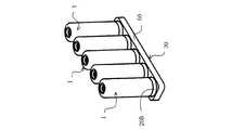
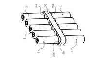
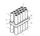
上記一実施形態では、セル1の数が3個であったが、図5のセルモジュールでは、それ以上の数(この場合5個)のセル1をバスバープレート30に対し一直線上に配列している。また、図6のセルモジュールでは、5個のセル1をバスバープレート30の両面に配列している。さらに図7のセルモジュールでは、バスバープレート30の両面に複数のセル1を千鳥状に配列している。いずれの場合も、セル1はバスバープレート30によって直列に接続されている。
【0040】
B.バスバープレートの形態
図8〜図10は、バスバープレートの他の形態を示しており、このバスバープレート30Bは、正極バスバー端子40Aと負極バスバー端子50Bとにより構成される端子接続部37に対し、2つの共通のバスバー70が、両端部に形成された接続用の孔70a,70bを利用して接続されている。すなわち、正極バスバー端子40Aは一方のバスバー70の孔70bに直接かしめ結合され、負極バスバー端子50Bは他方のバスバー70の孔70aにピン71を介してかしめ結合されている。この形態によれば、上記一実施形態のように、端部に配されるバスバー31,32と中間バスバー33といったように複数種類のバスバーを製作する必要がないので、コストダウンが図られる。
【0041】
C.セルの形態
図11および図12に示すセル1は、各端子10A,20Bが設けられた一端とは反対側の頭部の端面に、工具によってセル1を軸回りに回転させるための工具係合部が設けられている。図11の工具係合部は星形の穴80であり、図12の工具係合部は星形の突起81である。これらセル1によれば、セル1をバスバープレート30の端子接続部37にねじ込んで締結する際に、工具係合部(穴80,突起81)に係合させた工具によって強い締結トルクを与えることができ、セル1の接続強度を向上させることができる。
【0042】
図13(a)に示すセル1は、ケーシング2が全長にわたって断面六角形状に形成されており、ケーシング2の全体が工具係合部2aをなしている。また、図13(b)に示すセル1のケーシング2は、ケーシング2の頭部側の1/2の長さの部分が、断面六角形状に形成され、この部分が工具係合部2aをなしている。これらのセル1においては、筒状レンチをケーシング2の頭部、すなわち工具係合部2aの頭部に嵌合させてセル1を回転させることにより、強い締結トルクを与えることができる。
【0043】
(2)第2実施形態
次に、図14〜図16を参照して本発明の第2実施形態を説明する。
第2実施形態においては、正極および負極の端子が一端側に設けられているセルの基本構成は上記第1実施形態と同様であるが、バスバーへの取付部であるセルのネジ部が円柱状の内側セル端子に形成され、バスバープレートがこれに対応している点が、第1実施形態と異なっている。
【0044】
図14に示すように、セル1の一端(図14で下端)には、正極セル端子10Aと負極セル端子20Bとが、ケーシング2と同軸的に配設されている。負極セル端子20Bはリング状でセル1の端面を形成している。正極セル端子10Aは中実の円柱状突起で、負極セル端子20Bの内側に配設されており、負極セル端子20Bから突出している。そして、その外周面には、雄ネジ部12が形成されている。正極セル端子10Aと負極セル端子20Bとの間には、リング状の絶縁材11が介在されている。
【0045】
図14〜図16では、上記第1実施形態の中間バスバー33と同様の中間バスバー90を示している。この中間バスバー90は、図14および図15に示すように、長方形で板状のバスバー本体91の一端にリング状の負極バスバー端子50Bが一体成形され、バスバー本体91の他端に形成されたかしめ孔92に、正極バスバー端子40Aがかしめ結合された構成である。正極バスバー端子40Aは筒状で、その内周面には、セル1の正極セル端子10Aに形成されている雄ネジ部12が螺合可能な雌ネジ部41が形成されている。
【0046】
中間バスバー90は、複数が組み合わされてバスバープレートを構成する。その組み合わせは、負極バスバー端子50B内に正極バスバー端子40Aを裏側(図14で下側)から挿入し、かつ、バスバー本体91を一直線上に整列させて組み合わせられる。中間バスバー90の組み合わせ状態は、上記第1実施形態と同様に、バスバープレートを構成する図示せぬ樹脂モールドで保持され、正極バスバー端子40Aの外周面と負極バスバー端子50Bの内周面との間のほとんどが、樹脂モールドで埋められる。このように組み合わされた状態で、一対の正極バスバー端子40Aおよび負極バスバー端子50Bにより、本実施形態の端子接続部37が構成される。
【0047】
本実施形態では、正極セル端子10Aおよび負極セル端子20Bが設けられていない側のセル1の端部(頭部)を持ち、セル1の正極セル端子10Aの雄ネジ部12を、バスバー90の正極バスバー端子40Aの雌ネジ部41に嵌め合わせ、セル1をねじ込み方向である軸回りに回転させる。セル1の正極セル端子10Aはバスバー90の正極バスバー端子40Aに螺合し、セル1の負極セル端子20Bはバスバー90の負極バスバー端子50Bに突き当たって接触する。この時点で、正極セル端子10Aと正極バスバー端子40Aとの間にはねじ込み代が空いており、さらにセル1をねじ込み方向に回転させる力を与えて、正極セル端子10Aを正極バスバー端子40Aに締結する。以上の接続作業を行って、セルモジュールを得る。
【0048】
図16に示すように、セル1においては、正極セル端子10Aとバスバー90の正極バスバー端子40Aがネジ結合により接触し、一方、セル1のねじ込み作用により、負極セル端子20Bがバスバー90の負極バスバー端子50Bに突き当たって接触する。この接続形態により、セル1の正極セル端子10Aと負極セル端子20Bとがバスバー90の端子接続部37を介して直列接続され、セルモジュールが構成される。本実施形態のセルモジュール構造においても、セル1をバスバーにねじ結合する接続形態によって、上記第1実施形態と同様の効果を得ることができる。
【0049】
(3)第3実施形態
次に、図17を参照して本発明の第3実施形態を説明する。
円筒状のケーシング2を主体とするセル1の一端(図17で下端)には、円筒状の負極セル端子20Bが設けられ、その内部の中心に、円柱状突起からなる正極セル端子10Aが同軸的に配設されている。これら端子20B,10Aの高さは、端面が同一面内に存するようにほぼ等しくされている。
【0050】
図17の符合100は、第1実施形態の中間バスバー33と同様のバスバーであり、これらバスバー100が組み合わされてバスバープレート30の一部が構成される。バスバー100は、板状のバスバー本体101の一端に円筒状の負極バスバー端子50Bが一体成形され、バスバー本体101の他端に、円筒状の正極バスバー端子40Aが溶接等の手段により接合された構成である。負極バスバー端子50Bの先端側外周面には、導電性を有するリング状の外側ソケット110Bが固着されている。正極バスバー端子40Aの中心には断面円形の凹所42が形成されており、その内周面には、導電性を有するリング状の内側ソケット120Aが嵌合されている。
【0051】
バスバー100どうしは、負極バスバー端子50B内に円筒状の絶縁材130を嵌合させてから、この絶縁材130内に正極バスバー端子40Aを裏側(図17で下側)から挿入することにより組み合わされる。この組み合わせ状態における一対の正極バスバー端子40Aおよび負極バスバー端子50Bにより、端子接続部37が構成される。
【0052】
セル1の負極セル端子20Bの内周面と外側ソケット110Bには、負極セル端子20Bが外側ソケット110Bに対して軸方向に着脱自在に嵌合可能な嵌合手段が設けられている。また、セル1の正極セル端子10Aの外周面と内側ソケット120Aには、正極セル端子10Aが内側ソケット120Aに対して軸方向に着脱自在に嵌合可能な嵌合手段が設けられている。
【0053】
本実施形態では、正極セル端子10Aおよび負極セル端子20Bが設けられていない側のセル1の端部(頭部)を持ち、軸方向に移動させながら、正極セル端子10Aを正極バスバー端子40A内の内側ソケット120Aに嵌合させると同時に、負極セル端子20Bを負極バスバー端子50Bの外側ソケット110Bに嵌合させる。正極セル端子10Aの先端が正極バスバー端子40Aの底部に突き当たった段階で、嵌合は完了する。正極セル端子10Aは、その先端が正極バスバー端子40Aの底部に直接接続され、また、内側ソケット120Aを介して正極バスバー端子40Aの内周面に接続される。また、負極セル端子20Bは、外側ソケット110Bを介して負極バスバー端子50Bの外周面に接続される。このようにセル1の正極セル端子10Aと負極セル端子20Bとがバスバー100の端子接続部37を介して直列接続され、セルモジュールが構成される。
【0054】
本実施形態によれば、セル1を回転させることなく単に軸方向に移動させながら各セル端子10A,20Bを端子接続部37の各バスバー端子40A,50Bに嵌合させることにより、セル1を端子接続部37に接続させることができる。このため、ねじ締結と比べるとその脱着作業が一層容易である。また、ねじ込み時の締結トルクを発生させるための構造や、ねじ込み用の工具等が一切不要となる利点も備える。
【0055】
なお、上記第1〜第3実施形態では、負極を外側、正極を内側としているが、極性の配列はこの逆としてもよい。
【0056】
【発明の効果】
以上説明したように本発明によれば、セルの一端に互いに極性の異なる端子を同軸的に配設し、これら端子をバスバープレートの端子接続部に接続する構造であるから、セルの接続作業がきわめて容易になり、かつ、低抵抗化が図られるとともに、セルの緻密なレイアウトが可能となって空間の有効利用が図られ、さらに、誤組、端子の損傷および短絡を防止することができる。
【図面の簡単な説明】
【図1】 本発明の第1実施形態に係るセルモジュールであって、セルをバスバープレートに組み付ける前の状態を示す斜視図である。
【図2】 本発明の第1実施形態に係るセルモジュールであって、セルをバスバープレートに組み付けた状態を示す斜視図である。
【図3】 本発明の第1実施形態に係るセルモジュールであって、セルをバスバープレートに組み付ける前の状態を示す縦断面図である。
【図4】 本発明の第1実施形態に係るセルモジュールであって、セルをバスバープレートに組み付けた状態を示す縦断面図である。
【図5】 セルの数を増やした第1実施形態の変形例の斜視図である。
【図6】 バスバープレートの両面にセルを配列した第1実施形態の変形例の斜視図である。
【図7】 バスバープレートの両面にセルを千鳥配列した第1実施形態の変形例の斜視図である。
【図8】 バスバーの変形例を示す斜視図である。
【図9】 同縦断面図である。
【図10】同下面図である。
【図11】工具係合部を設けたセルの変形例を示す図であって、(a)は平面図、(b)は側面図である。
【図12】工具係合部を設けたセルの他の変形例を示す図であって、(a)は平面図、(b)は側面図である。
【図13】(a),(b)とも、工具係合部を設けたセルのさらに他の変形例を示す斜視図である。
【図14】本発明の第2実施形態に係るセルモジュールであって、セルをバスバープレートに組み付ける前の状態を示す斜視図である。
【図15】本発明の第2実施形態のバスバーの下面図である。
【図16】本発明の第2実施形態に係るセルモジュールであって、セルをバスバープレートに組み付けた状態を示す斜視図である。
【図17】本発明の第3実施形態に係るセルモジュールを示す断面図である。
【図18】従来のセルモジュール構造の一例を示す斜視図である。
【符号の説明】
1…セル
10A…正極セル端子(内側セル端子)
12…正極セル端子の雄ネジ部(外側セル端子のネジ部)
20B…負極セル端子(外側セル端子)
21…負極セル端子の雌ネジ部(外側セル端子のネジ部)
30…バスバープレート
37…端子接続部
40A…正極バスバー端子(内側接続端子)
41…正極バスバー端子の雌ネジ部(内側接続端子のネジ部)
50B…負極バスバー端子(外側接続端子)
51…負極バスバー端子の雄ネジ部(外側接続端子のネジ部)[0001]
BACKGROUND OF THE INVENTION
The present invention relates to a structure of a cell module mounted as a drive power source in an electric vehicle, a hybrid electric vehicle, or the like. The cell referred to in the present invention includes all electric storage elements such as single batteries such as nickel metal hydride and lithium batteries, and energy storage elements such as electric double layer capacitors (ultracapacitors).
[0002]
[Prior art]
As a cell module in which a plurality of cells are connected in series, for example, a plurality of cylindrical or rectangular parallelepiped cells in which a positive electrode terminal and a negative electrode terminal are arranged at one end are installed in parallel, and a positive electrode terminal and a negative electrode terminal of adjacent cells Are connected in series via a bus bar. In general, the bus bar is attached to the terminal when assembling such a cell module by bolt connection or nut connection.
[0003]
FIG. 18 shows an example of a
[0004]
[Problems to be solved by the invention]
In the conventional cell module structure in which a plurality of cells are connected in series on the basis of the connection form shown in FIG. 18, the connection between the terminals by the bus bar repeats the work of fastening the bolt after the positioning of the bus bar with respect to the terminal. Therefore, it takes time to connect. Moreover, in order to fasten the bolts, in addition to requiring a large work space for operating the fastening tool, it is necessary to consider that a short circuit does not occur due to the fastening tool. It had been.
[0005]
In addition, in order to reduce the connection resistance, it is necessary to strengthen the connection state between the terminal and the bus bar, but the load applied to the connection portion is increased due to deformation due to vibration or temperature change, and the connection state. There was a risk of adverse effects. Therefore, the cell is held by the holding member to reduce the load on the connection portion, but this leads to an increase in the number of parts and a complicated structure.
[0006]
In addition, in a cell in which a positive electrode terminal and a negative electrode terminal are arranged side by side at one end, the occupied area of the entire cell and cell module tends to be large, and in a vehicle that is required to effectively use a limited space, It is an unfavorable structure.
[0007]
Furthermore, although the positive and negative terminals are changed in shape to prevent misassembly that connects the positive terminals or the negative terminals, the terminal is often a protrusion. Could not be completely prevented. In addition, since the terminal is a protrusion, there is a risk that the terminal may be accidentally damaged and sufficient electrical contact cannot be achieved or a short circuit may occur.
[0008]
Therefore, the present invention satisfies the following matters.Cell module The purpose is to provide.
[1] Cell connection is facilitated and resistance is reduced.
[2] A precise layout of cells is possible, and space can be used effectively.
[3] It is possible to prevent erroneous assembly, terminal damage and short circuit.
[0009]
[Means for Solving the Problems]
The present invention provides a cylindrical cellAnd a bus bar plate having a terminal connection for connecting the cells The inner cell terminal and the outer cell terminal having different polarities are coaxially arranged at one end of the cell, while the bus bar plate has a terminal connection portion connected to the inner cell terminal and the outer cell terminal of the cell. Corresponding inner connection terminals and outer connection terminals are arranged coaxially,By approaching the cell and the busper plate in the axial direction without relatively rotating, Cell outer cell terminalWhen Outside connection terminal of terminal connectionAnd mating In addition, the inner cell terminal and the inner connection terminalMating The inner cell terminal and the outer cell terminal of the cell are connected to the terminal connection portion of the bus bar plate according to the connection form. In the present invention, each cell terminal of the cell and each connection terminal in the terminal connection portion of the bus bar plateMating Holding the part by welding or gluing.
[0010]
The cell terminals (positive and negative terminals) of the present invention are coaxially arranged at one end as an inner cell terminal and an outer cell terminal, and the terminal connection portion of the bus bar plate corresponds to each terminal of the cell. An inner connection terminal and an outer connection terminal are provided. Then, each cell-side terminal is brought into contact with each terminal on the terminal connection portion side to constitute a cell module. The coaxial arrangement of the positive and negative terminals facilitates the connection of the cell to the terminal connecting portion, and the power transmission distance is extremely shortened, thereby reducing the resistance. Further, since the occupied area of the entire cell and cell module is reduced, a limited space can be used effectively, and a dense layout is possible when a plurality of cells and cell modules are connected. Further, the connection work is facilitated in that the polarity is eliminated and the need to connect the cell to the terminal connection portion, and the wrong assembly between the same poles and the accompanying short circuit are prevented.
[0011]
Next, as a more specific means of the present invention, among the inner and outer cell terminals arranged coaxially at one end of the cell, at least the outer cell terminal is formed in a cylindrical shape, and the inner circumference thereof On the other hand, a threaded portion is formed on the surface or outer peripheral surface, and on the other hand, an inner connection terminal and an outer connection terminal corresponding to the inner cell terminal and the outer cell terminal of the cell are coaxially arranged in the terminal connection portion of the bus bar plate. In addition, the outer connection terminal is formed with a screw portion into which the screw portion of the outer cell terminal is screwed, and the screw portion of the outer cell terminal is screwed into the screw portion of the outer connection terminal of the terminal connection portion. Accordingly, the inner cell terminal and the outer cell terminal of the cell are connected via the terminal connection portion of the bus bar plate by a connection form in which the inner cell terminal and the inner connection terminal come into contact with each other.
[0012]
According to this invention, the cell is rotated around the axis, and the screw portion provided on the outer cell terminal of the cell is screwed to the screw portion provided on the outer connection terminal of the terminal connection portion to be fastened. As a result, the outer cell terminal of the cell and the outer connection terminal of the terminal connection portion come into contact with each other by screw coupling, while the inner cell terminal of the cell hits and comes into contact with the inner connection terminal of the terminal connection portion by the screwing action of the cell. . With this connection form, the inner cell terminal and the outer cell terminal of the cell are connected to the terminal connection portion of the bus bar plate.
[0013]
Furthermore, as another specific means of the present invention, of the inner and outer cell terminals arranged coaxially at one end of the cell, the inner cell terminal has a cylindrical shape, and a screw portion is formed on the outer peripheral surface thereof. On the other hand, the inner connection terminal and the outer connection terminal corresponding to the inner cell terminal and the outer cell terminal of the cell are coaxially arranged at the terminal connection portion of the bus bar plate, and the inner connection terminal has an inner cell. A screw part is formed in which the screw part of the terminal is screwed. As the screw part of the inner cell terminal is screwed into the screw part of the inner connection terminal of the terminal connection part, the outer cell terminal and the outer connection terminal are formed. The inner cell terminal and the outer cell terminal of the cell are connected via the terminal connection portion of the bus bar plate by the connection form in which the two contact each other.
[0014]
In the present invention, a threaded portion is formed on the inner cell terminal side, the cell is rotated around its axis, and the threaded portion of the inner cell terminal of the cell is screwed to the threaded portion of the inner connecting terminal of the terminal connecting portion. Conclude. As a result, the inner cell terminal of the cell and the inner connection terminal of the terminal connection portion come into contact with each other by screw coupling, while the outer cell terminal of the cell hits and comes into contact with the outer connection terminal of the bus bar plate due to the screwing action of the cell. With this connection form, the inner cell terminal and the outer cell terminal of the cell are connected to the terminal connection portion of the bus bar plate.
[0015]
According to the connection form using the screw connection between the terminals as described above, the contact surface pressure between the terminals can be sufficiently secured, and the transmission distance of the power becomes extremely short, so that the resistance can be greatly reduced. It is done. Moreover, since the rigidity of the connection state between the terminal on the cell side and the terminal on the terminal connection portion side can be increased by fastening the screw, the connection state is firmly maintained and the reduction in resistance is promoted. In particular, when the screw fastening portion of the cell is provided at the outer cell terminal, the rigidity in the connected state is higher than when the cell is provided at the inner cell terminal, and the above-described effect can be further obtained.
[0016]
Further, since the cell is connected to the terminal connecting portion by simply screwing the cell into the terminal connecting portion of the bus bar plate, a fastening member such as a bolt or a nut and a fastening tool are not required. For this reason, the connection work can be performed very easily, and the work space can be reduced. In addition, the occupied area of the cells and the entire cell module is small, and the limited space can be effectively used. Further, the connection work is facilitated in that the polarity of the cell terminals is determined and the necessity of connecting to the bus bar plate is eliminated, and further, misconfiguration between the same poles and the accompanying short circuit are prevented.
[0017]
The present invention is based on a structure in which cells are connected to the terminal connection portion of the bus bar plate, but is extremely suitable for constructing a cell module in which a plurality of cells are connected. As its structure, a plurality of terminal connection portions are provided in series on one side of the bus bar plate, and a plurality of cells are connected to these terminal connection portions in the above connection form. Further, a plurality of terminal connection portions are provided in series on both surfaces of the bus bar plate, and a plurality of cells are connected to these terminal connection portions in the above connection form.
[0018]
If a plurality of cells are connected in series in this manner, the cell layout can be made minute by minimizing the distance between adjacent cells, and the entire cell module can be made compact and the space can be effectively used.
[0019]
In the present invention, the following modes can be adopted.
(1) The outer cell terminal of the cell is formed into a cylindrical shape, the inner cell terminal is disposed therein, and the height of the outer cell terminal is made higher than the height of the inner cell terminal. According to this, the inner cell terminal is protected by the outer cell terminal. If this configuration is applied to an invention in which a threaded portion is formed on the inner peripheral surface of the outer cell terminal, there is little possibility of damaging the end surface of the inner cell terminal and the threaded portion of the outer cell terminal, which are substantial power transfer portions. Become. Further, if the present invention is applied to the invention in which the threaded portion is formed on the outer peripheral surface of the inner cell terminal, the possibility of damaging the end surface of the outer cell terminal and the threaded portion of the inner cell terminal, which are substantial power transfer portions, is reduced. In either case, the problem that sufficient electrical contact cannot be achieved is eliminated, and the possibility of shorting both terminals is reduced.
[0020]
(2) Contrary to the above (1), the height of the inner cell terminal is made to be higher than the height of the outer cell terminal.
[0021]
(3) An insulating material is interposed between the outer cell terminal and the inner cell terminal of the cell to ensure short circuit prevention. Further, this insulating material is projected higher than the outer cell terminal and the inner cell terminal. Let In this case, the outer cell terminal and the inner cell terminal can be protected by the insulating material.
[0022]
{Circle around (4)} A conductive elastic member is sandwiched between the connecting portions of the terminals by contact rather than the connection between the screw portions, and the terminals are electrically connected via this elastic member. As the elastic member, a helicate or the like is preferably used.
[0023]
(5) A tool engaging portion for rotating the cell around the axis by a tool is provided on the other end surface of the cell opposite to the end provided with the outer cell terminal and the inner cell terminal. Examples of the tool engaging portion include holes or protrusions having a polygonal cross section or a star cross section. According to this, when the cell is screwed into the terminal connection portion of the bus bar plate and fastened, a strong fastening torque can be given by the tool engaged with the tool engaging portion such as a wrench, and the connection strength can be improved. it can.
(6) As a modified example of the tool engaging portion in the above (5), it is assumed that a partial cross section of the cell is formed in a polygonal shape. Examples of the cross-sectional shape include a quadrangle and a hexagon that can rotate the cell with a tool such as a cylindrical wrench. Note that the cell may have a polygonal cross-section. Also by this modification, the effect (5) can be obtained.
[0024]
DETAILED DESCRIPTION OF THE INVENTION
(1) First embodiment
Hereinafter, a first embodiment of the present invention will be described with reference to FIGS.
1,
[0025]
First, the structure of the
The
[0026]
The positive
[0027]
On the other hand, the
[0028]
The
[0029]
In the
[0030]
In the combined state of the bus bars 31, 32, 33 held by the
[0031]
Next, a method for configuring a cell module by incorporating a plurality of
[0032]
In each
[0033]
In the present embodiment, the
[0034]
Further, the
[0035]
Further, by connecting a plurality of
[0036]
Further, at each terminal of the
[0037]
In the above embodiment, the
[0038]
Next, another embodiment based on the first embodiment will be described. In these other embodiments, the same reference numerals are given to the same components as those in the above embodiment, and the description thereof is omitted.
[0039]
A. Number of cells connected and arrangement
In the above embodiment, the number of
[0040]
B. Form of bus bar plate
8 to 10 show other forms of the bus bar plate. The
[0041]
C. Cell shape
The
[0042]
In the
[0043]
(2) Second embodiment
Next, a second embodiment of the present invention will be described with reference to FIGS.
In the second embodiment, the basic configuration of the cell in which the positive and negative terminals are provided on one end side is the same as that of the first embodiment, but the screw portion of the cell, which is the mounting portion to the bus bar, is cylindrical. Is different from the first embodiment in that the bus bar plate is formed on the inner cell terminal.
[0044]
As shown in FIG. 14, the positive
[0045]
14 to 16, an
[0046]
A plurality of intermediate bus bars 90 are combined to form a bus bar plate. The combination is performed by inserting the positive
[0047]
In the present embodiment, the end portion (head) of the
[0048]
As shown in FIG. 16, in the
[0049]
(3) Third embodiment
Next, a third embodiment of the present invention will be described with reference to FIG.
A cylindrical negative
[0050]
[0051]
The bus bars 100 are combined by inserting a cylindrical insulating
[0052]
The inner peripheral surface of the
[0053]
In the present embodiment, the
[0054]
According to the present embodiment, the
[0055]
In the first to third embodiments, the negative electrode is on the outer side and the positive electrode is on the inner side, but the polarity arrangement may be reversed.
[0056]
【The invention's effect】
As described above, according to the present invention, terminals having different polarities are coaxially arranged at one end of the cell, and these terminals are connected to the terminal connection portion of the bus bar plate. It becomes extremely easy and the resistance can be reduced, and the cell can be precisely laid out to make effective use of the space. Further, erroneous assembly, terminal damage and short circuit can be prevented.
[Brief description of the drawings]
FIG. 1 is a perspective view illustrating a cell module according to a first embodiment of the present invention before a cell is assembled to a bus bar plate.
FIG. 2 is a perspective view showing the cell module according to the first embodiment of the present invention in a state where the cells are assembled to the bus bar plate.
FIG. 3 is a vertical cross-sectional view showing the cell module according to the first embodiment of the present invention before the cells are assembled to the bus bar plate.
FIG. 4 is a vertical cross-sectional view showing the cell module according to the first embodiment of the present invention in a state where the cells are assembled to the bus bar plate.
FIG. 5 is a perspective view of a modified example of the first embodiment in which the number of cells is increased.
FIG. 6 is a perspective view of a modified example of the first embodiment in which cells are arranged on both sides of a bus bar plate.
FIG. 7 is a perspective view of a modified example of the first embodiment in which cells are arranged in a staggered manner on both surfaces of a bus bar plate.
FIG. 8 is a perspective view showing a modification of the bus bar.
FIG. 9 is a longitudinal sectional view of the same.
FIG. 10 is a bottom view of the same.
FIGS. 11A and 11B are diagrams showing a modified example of a cell provided with a tool engaging portion, where FIG. 11A is a plan view and FIG. 11B is a side view.
FIGS. 12A and 12B are diagrams showing another modification of the cell provided with the tool engaging portion, where FIG. 12A is a plan view and FIG. 12B is a side view;
FIGS. 13A and 13B are perspective views showing still another modified example of the cell provided with the tool engaging portion. FIGS.
FIG. 14 is a perspective view showing the cell module according to the second embodiment of the present invention before the cells are assembled to the bus bar plate.
FIG. 15 is a bottom view of a bus bar according to a second embodiment of the present invention.
FIG. 16 is a perspective view showing a cell module according to a second embodiment of the present invention in a state where the cells are assembled to the bus bar plate.
FIG. 17 is a cross-sectional view showing a cell module according to a third embodiment of the present invention.
FIG. 18 is a perspective view showing an example of a conventional cell module structure.
[Explanation of symbols]
1 ... cell
10A ... Positive electrode cell terminal (inner cell terminal)
12 ... Male screw part of positive cell terminal (screw part of outer cell terminal)
20B ... Negative electrode cell terminal (outside cell terminal)
21 ... Female screw part of negative cell terminal (screw part of outer cell terminal)
30 ... Bus bar plate
37 ... Terminal connection
40A ... Positive bus bar terminal (inner connection terminal)
41 ... Female screw part of positive bus bar terminal (screw part of inner connection terminal)
50B ... Negative electrode bus bar terminal (outside connection terminal)
51 ... Male screw part of negative electrode bus bar terminal (screw part of outer connection terminal)
Claims (6)
Translated fromJapaneseセルの一端に、互いに極性の異なる内側セル端子と外側セル端子とが同軸的に配設され、
一方、バスバープレートの端子接続部には、前記セルの内側セル端子および外側セル端子に対応した内側接続端子および外側接続端子が同軸的に配設されており、
前記セルと前記バスパープレートとを相対的に回転させることなく軸方向に接近させることによって、前記セルの外側セル端子と前記端子接続部の外側接続端子とが嵌合するとともに、内側セル端子と内側接続端子とが嵌合する接続形態により、セルの内側セル端子と外側セル端子とがバスバープレートの端子接続部に接続されていることを特徴とするセルモジュール。A cell module comprising a cylindrical celland a bus bar plate having a terminal connection part for connecting the cell ,
An inner cell terminal and an outer cell terminal having different polarities are coaxially arranged at one end of the cell,
On the other hand, in the terminal connection portion of the bus bar plate, the inner connection terminal and the outer connection terminal corresponding to the inner cell terminal and the outer cell terminal of the cell are disposed coaxially,
By bringing the cell and the busper plate close to each other in the axial direction without rotating relatively, the outer cell terminalof the celland the outer connection terminal of the terminal connection portionare fitted , and the inner cell terminal and the inner cell terminal Acell module , wherein an inner cell terminal and an outer cell terminal of a cell are connected to a terminal connection portion of a bus bar plate by a connection form in which the connection terminalis fitted .
セルの一端に、互いに極性の異なる内側セル端子と外側セル端子とが同軸的に配設され、かつ、少なくとも外側セル端子が筒状に形成されているとともに、その内周面または外周面にネジ部が形成されており、
一方、バスバープレートの端子接続部には、前記セルの内側セル端子および外側セル端子に対応した内側接続端子および外側接続端子が同軸的に配設され、かつ、外側接続端子には、外側セル端子のネジ部が螺合するネジ部が形成されており、
前記セルにおける外側セル端子のネジ部が、前記端子接続部における外側接続端子のネジ部に螺合されるに伴い、内側セル端子と内側接続端子とが当接する接続形態により、セルの内側セル端子と外側セル端子とがバスバープレートの端子接続部に接続されていることを特徴とするセルモジュール。A cell module comprising a cylindrical celland a bus bar plate having a terminal connection part for connecting the cell ,
An inner cell terminal and an outer cell terminal having different polarities are coaxially disposed at one end of the cell, and at least the outer cell terminal is formed in a cylindrical shape, and a screw is provided on the inner peripheral surface or the outer peripheral surface thereof. Part is formed,
Meanwhile, an inner connection terminal and an outer connection terminal corresponding to the inner cell terminal and the outer cell terminal of the cell are coaxially arranged at the terminal connection portion of the bus bar plate, and the outer cell terminal has an outer cell terminal. The screw part that the screw part of is screwed is formed,
The inner cell terminal of the cell has a connection configuration in which the inner cell terminal and the inner connection terminal come into contact with each other as the screw portion of the outer cell terminal in the cell is screwed to the screw portion of the outer connection terminal in the terminal connection portioncell module, wherein a outer cell terminal is connected to the terminal connecting portion of the bus bar plate and.
セルの一端に、互いに極性の異なる内側セル端子と外側セル端子とが同軸的に配設され、かつ、内側セル端子は円柱状であって、その外周面にネジ部が形成されており、
一方、バスバープレートの端子接続部には、前記セルの内側セル端子および外側セル端子に対応した内側接続端子および外側接続端子が同軸的に配設され、かつ、内側接続端子には、内側セル端子のネジ部が螺合するネジ部が形成されており、
前記セルにおける内側セル端子のネジ部が、前記端子接続部における内側接続端子のネジ部に螺合されるに伴い、外側セル端子と外側接続端子とが当接する接続形態により、セルの内側セル端子と外側セル端子とがバスバープレートの端子接続部に接続されていることを特徴とするセルモジュール。A cell module comprising a cylindrical celland a bus bar plate having a terminal connection part for connecting the cell ,
An inner cell terminal and an outer cell terminal having different polarities are coaxially arranged at one end of the cell, and the inner cell terminal is cylindrical, and a screw portion is formed on the outer peripheral surface thereof,
On the other hand, in the terminal connection portion of the bus bar plate, the inner connection terminal and the outer connection terminal corresponding to the inner cell terminal and the outer cell terminal of the cell are coaxially arranged, and the inner connection terminal includes the inner cell terminal. The screw part that the screw part of is screwed is formed,
As the screw portion of the inner cell terminal in the cell is screwed into the screw portion of the inner connection terminal in the terminal connection portion, the inner cell terminal of the cell is brought into contact with the outer cell terminal and the outer connection terminal.cell module, wherein a outer cell terminal is connected to the terminal connecting portion of the bus bar plate and.
Priority Applications (3)
| Application Number | Priority Date | Filing Date | Title |
|---|---|---|---|
| JP2000383402AJP3759872B2 (en) | 2000-05-12 | 2000-12-18 | Cell module |
| US09/849,590US6656632B2 (en) | 2000-05-12 | 2001-05-07 | Cell module structure |
| DE10122682ADE10122682B4 (en) | 2000-05-12 | 2001-05-10 | Cell module structure |
Applications Claiming Priority (3)
| Application Number | Priority Date | Filing Date | Title |
|---|---|---|---|
| JP2000-140834 | 2000-05-12 | ||
| JP2000140834 | 2000-05-12 | ||
| JP2000383402AJP3759872B2 (en) | 2000-05-12 | 2000-12-18 | Cell module |
Publications (2)
| Publication Number | Publication Date |
|---|---|
| JP2002033088A JP2002033088A (en) | 2002-01-31 |
| JP3759872B2true JP3759872B2 (en) | 2006-03-29 |
Family
ID=26591820
Family Applications (1)
| Application Number | Title | Priority Date | Filing Date |
|---|---|---|---|
| JP2000383402AExpired - Fee RelatedJP3759872B2 (en) | 2000-05-12 | 2000-12-18 | Cell module |
Country Status (3)
| Country | Link |
|---|---|
| US (1) | US6656632B2 (en) |
| JP (1) | JP3759872B2 (en) |
| DE (1) | DE10122682B4 (en) |
Cited By (1)
| Publication number | Priority date | Publication date | Assignee | Title |
|---|---|---|---|---|
| KR20160100673A (en)* | 2015-02-16 | 2016-08-24 | 삼성에스디아이 주식회사 | Battery pack |
Families Citing this family (60)
| Publication number | Priority date | Publication date | Assignee | Title |
|---|---|---|---|---|
| JP4733248B2 (en)* | 2000-06-20 | 2011-07-27 | 本田技研工業株式会社 | Cell module structure |
| JP3572404B2 (en)* | 2002-03-04 | 2004-10-06 | 日産自動車株式会社 | Battery pack |
| US6773301B1 (en)* | 2003-05-08 | 2004-08-10 | Jeffrey R. Chaskin | Cell strap for combining cells into a battery |
| EP1526590A2 (en)* | 2003-09-22 | 2005-04-27 | Fuji Photo Film Co., Ltd. | Battery and a pair of contacts, and lens-fitted photo film unit |
| US20060110630A1 (en)* | 2004-11-23 | 2006-05-25 | Michael Herman | Battery with integrated screwdriver |
| JP4923511B2 (en)* | 2004-12-27 | 2012-04-25 | 日産自動車株式会社 | Assembled battery |
| US20060141329A1 (en) | 2004-12-28 | 2006-06-29 | Utc Fuel Cells, Llc | Fuel cell demineralizers integrated with coolant accumulator |
| JP2006351982A (en)* | 2005-06-20 | 2006-12-28 | Matsushita Electric Ind Co Ltd | Capacitor device |
| DE102005042169B4 (en)* | 2005-09-06 | 2014-04-03 | Dilo Trading Ag | Using an array of lithium polymer batteries |
| US8568915B2 (en)* | 2006-08-11 | 2013-10-29 | Johnson Controls—SAFT Power Solutions LLC | Battery with integrally formed terminal |
| US11660971B2 (en) | 2006-11-07 | 2023-05-30 | Clarios Advanced Solutions Llc | System for arranging and coupling battery cells in a battery module |
| CN101627490B (en)* | 2006-12-14 | 2012-10-03 | 江森自控帅福得先进能源动力系统有限责任公司 | Battery module |
| CN101849301B (en) | 2007-07-30 | 2016-07-06 | 江森自控帅福得先进能源动力系统有限责任公司 | Storage battery arrangement |
| US20090075163A1 (en)* | 2007-09-14 | 2009-03-19 | Ford Global Technologies, Llc | System and method for electrically connecting terminals of a battery |
| DE102007063195B4 (en)* | 2007-12-20 | 2013-08-29 | Daimler Ag | Battery with a housing and a heat conducting plate |
| DE102008013188A1 (en)* | 2008-03-07 | 2009-09-17 | Johnson Controls Hybrid And Recycling Gmbh | Electrochemical accumulator and vehicle with an electrochemical accumulator |
| DE102008034865B4 (en)* | 2008-07-26 | 2012-07-26 | Daimler Ag | Battery with several battery cells |
| US8999538B2 (en)* | 2008-08-14 | 2015-04-07 | Johnson Controls—SAFT Advanced Power Solutions LLC | Battery module with sealed vent chamber |
| EP2351119B1 (en) | 2008-11-12 | 2015-09-23 | Johnson Controls Saft Advanced Power Solutions LLC | Battery system with heat exchanger |
| KR20110042376A (en)* | 2009-07-17 | 2011-04-26 | 파나소닉 주식회사 | Battery and Battery Module |
| KR101136310B1 (en)* | 2010-06-07 | 2012-04-19 | 에스비리모티브 주식회사 | Battery pack |
| KR101890830B1 (en)* | 2010-10-29 | 2018-08-22 | 다나 캐나다 코포레이션 | Heat exchanger and battery unit structure for cooling thermally conductive batteries |
| ES2430855T3 (en)* | 2010-12-23 | 2013-11-22 | Outils Wolf | Pivoting Battery Connection |
| JP5757180B2 (en) | 2011-07-11 | 2015-07-29 | 株式会社オートネットワーク技術研究所 | Battery wiring module cover, battery wiring module and battery module |
| KR101351903B1 (en)* | 2011-08-19 | 2014-01-17 | 주식회사 엘지화학 | Cabletype secondary battery |
| DE102011121488B4 (en)* | 2011-12-16 | 2020-01-23 | Audi Ag | Motor vehicle battery |
| US8916285B2 (en)* | 2011-12-28 | 2014-12-23 | General Electric Company | Modular high temperature battery electrical configurations |
| DE102012218162B4 (en)* | 2012-10-04 | 2023-12-14 | Bayerische Motorenwerke Aktiengesellschaft | Energy storage arrangement |
| DE102013202244A1 (en) | 2013-02-12 | 2014-08-14 | Robert Bosch Gmbh | A cell connector for electrically contacting a plurality of battery cell terminals, a method of manufacturing such a cell connector, and a battery module having at least one such cell connector |
| US9738976B2 (en) | 2013-02-27 | 2017-08-22 | Ioxus, Inc. | Energy storage device assembly |
| US9899643B2 (en) | 2013-02-27 | 2018-02-20 | Ioxus, Inc. | Energy storage device assembly |
| US9892868B2 (en) | 2013-06-21 | 2018-02-13 | Ioxus, Inc. | Energy storage device assembly |
| DE102013213550A1 (en)* | 2013-07-11 | 2015-01-15 | Robert Bosch Gmbh | Battery cell with a prismatic or cylindrical housing, battery module and motor vehicle |
| EP2879199A1 (en)* | 2013-09-10 | 2015-06-03 | Flextronics International Kft. | Energy storage device |
| TWM472958U (en)* | 2013-10-04 | 2014-02-21 | Jun-Hong Wu | Continuable power module and electric device including the same |
| GB2529612A (en)* | 2014-06-25 | 2016-03-02 | R & D Vehicle Systems Ltd | Device for a battery assembly |
| DE102014014850A1 (en) | 2014-10-07 | 2016-04-07 | Audi Ag | Energy storage arrangement, motor vehicle comprising such an energy storage device and method for their preparation |
| US9437860B2 (en) | 2014-11-20 | 2016-09-06 | Ford Global Technologies, Llc | Traction battery assembly having snap-in bus bar module |
| DE102015210671A1 (en)* | 2015-06-11 | 2016-12-15 | Robert Bosch Gmbh | Battery cell with a disposed within a second terminal first terminal |
| DE102015110243A1 (en)* | 2015-06-25 | 2016-12-29 | Schuler Pressen Gmbh | Battery cell housing, carrier and method for grouping a plurality of battery cell housings |
| EP3605649B1 (en)* | 2015-09-30 | 2021-06-02 | FDK Corporation | Battery pack protection element attachment tab, battery pack parallel fixing component, and battery pack |
| DE102016223194B4 (en)* | 2016-11-23 | 2018-07-26 | Robert Bosch Gmbh | Battery cell comprising at least one galvanic cell, battery and method for producing a battery cell |
| DE102016223187B3 (en) | 2016-11-23 | 2018-03-22 | Robert Bosch Gmbh | A battery comprising a first battery cell and a second battery cell and a method of electrically contacting a first battery cell with a second battery cell for assembling a battery |
| AT522004B1 (en)* | 2018-12-20 | 2021-12-15 | Raiffeisenlandesbank Oberoesterreich Ag | Contacting device for parallel and serial contacting of battery cells assembled into a module |
| CN113273016B (en)* | 2019-01-07 | 2024-08-23 | 卡诺科技公司 | Method and system for thermal management of battery packs |
| JP2020155286A (en)* | 2019-03-19 | 2020-09-24 | 株式会社Gsユアサ | Power storage device and bus bar |
| JP2020155283A (en)* | 2019-03-19 | 2020-09-24 | 株式会社Gsユアサ | Power storage element and power storage device |
| DE102019205051A1 (en)* | 2019-04-09 | 2020-10-15 | Audi Ag | Method for contacting a battery cell and battery contact arrangement designed as a round cell |
| DE102019207207A1 (en) | 2019-05-17 | 2020-11-19 | Volkswagen Aktiengesellschaft | Battery module for a motor vehicle |
| CN110854322A (en)* | 2019-09-20 | 2020-02-28 | 杭州乾代科技有限公司 | Modularized lithium battery module |
| CN110931680B (en)* | 2019-12-03 | 2020-10-23 | 东莞市创汇原电源技术有限公司 | Combined lithium battery shell |
| DE102020134689B4 (en) | 2020-12-22 | 2023-03-23 | Dr. Ing. H.C. F. Porsche Aktiengesellschaft | battery electric vehicle |
| CN112803122B (en)* | 2021-01-29 | 2023-07-28 | 嘉兴模度新能源有限公司 | Battery module with locking mechanism, array type large module, battery pack and power supply |
| DE102021108570A1 (en) | 2021-04-07 | 2022-10-13 | Bayerische Motoren Werke Aktiengesellschaft | Electrical energy storage device with a lateral cell contact system and motor vehicle |
| DE102021110025A1 (en) | 2021-04-21 | 2022-10-27 | Dr. Ing. H.C. F. Porsche Aktiengesellschaft | Battery cell mounting assembly and electric vehicle |
| CN114566765B (en)* | 2022-02-28 | 2024-05-31 | 中创新航科技股份有限公司 | A busbar assembly, assembly method thereof, assembly tool and battery pack |
| US20250246737A1 (en)* | 2024-01-29 | 2025-07-31 | GM Global Technology Operations LLC | Cell holder trays including electrical circuits for vehicle battery cells |
| DE102024103088A1 (en)* | 2024-02-05 | 2025-08-07 | Bayerische Motoren Werke Aktiengesellschaft | HVS concept with screwed battery cell |
| KR20250122178A (en)* | 2024-02-06 | 2025-08-13 | 주식회사 엘지에너지솔루션 | Battery cell assembly, battery pack, and vehicle having the same |
| DE102024103799A1 (en)* | 2024-02-12 | 2025-08-14 | Bayerische Motoren Werke Aktiengesellschaft | ENERGY STORAGE CELL, CARRIER PLATE AND BATTERY MODULE |
Family Cites Families (4)
| Publication number | Priority date | Publication date | Assignee | Title |
|---|---|---|---|---|
| DE220317C (en) | ||||
| US5104752A (en)* | 1990-10-15 | 1992-04-14 | Allied-Signal, Inc. | Dual, series/parallel battery cell connects |
| GB9219704D0 (en)* | 1992-09-17 | 1992-10-28 | Aabh Patent Holdings | Electrochemical cell |
| JP3344231B2 (en)* | 1996-08-21 | 2002-11-11 | 松下電器産業株式会社 | Battery connection structure |
- 2000
- 2000-12-18JPJP2000383402Apatent/JP3759872B2/ennot_activeExpired - Fee Related
- 2001
- 2001-05-07USUS09/849,590patent/US6656632B2/ennot_activeExpired - Fee Related
- 2001-05-10DEDE10122682Apatent/DE10122682B4/ennot_activeExpired - Fee Related
Cited By (2)
| Publication number | Priority date | Publication date | Assignee | Title |
|---|---|---|---|---|
| KR20160100673A (en)* | 2015-02-16 | 2016-08-24 | 삼성에스디아이 주식회사 | Battery pack |
| KR102381778B1 (en)* | 2015-02-16 | 2022-04-01 | 삼성에스디아이 주식회사 | Battery pack |
Also Published As
| Publication number | Publication date |
|---|---|
| DE10122682B4 (en) | 2006-04-27 |
| US20020006544A1 (en) | 2002-01-17 |
| US6656632B2 (en) | 2003-12-02 |
| JP2002033088A (en) | 2002-01-31 |
| DE10122682A1 (en) | 2001-11-29 |
Similar Documents
| Publication | Publication Date | Title |
|---|---|---|
| JP3759872B2 (en) | Cell module | |
| JP4733248B2 (en) | Cell module structure | |
| KR100684763B1 (en) | Unit battery connector on the secondary battery module and the secondary battery module | |
| KR101326196B1 (en) | Battery Pack of Compact Structure | |
| KR101305224B1 (en) | Battery Module and Battery Pack Comprising the Same | |
| JP4607733B2 (en) | Secondary battery and secondary battery module | |
| KR100778511B1 (en) | Secondary battery module | |
| CN102088068B (en) | Battery module and the battery pack comprising battery module | |
| KR101271567B1 (en) | Battery Module of Structure Having Fixing Member Inserted into Through-Hole of Plates and Battery Pack Employed with the Same | |
| KR20050106540A (en) | Secondary battery | |
| JP2011514636A (en) | Medium or large battery module having electrode terminal connecting member and insulating bonding member | |
| KR101970754B1 (en) | Battery cell assembly | |
| KR101441423B1 (en) | High-Voltage Battery with Integrated Battery Connector | |
| KR20170009135A (en) | Battery For Vehicle | |
| KR100570779B1 (en) | Secondary battery and secondary battery module comprising the connector with rotatable connector | |
| JP3511509B2 (en) | Cell module structure and cell connection members | |
| CN215989109U (en) | Storage battery energy storage system | |
| KR100590107B1 (en) | Secondary battery | |
| JP2000323109A (en) | Battery module | |
| KR100599806B1 (en) | Secondary battery module | |
| JP2006294985A5 (en) | ||
| KR20070049255A (en) | Thin battery of novel structure and battery module consisting of | |
| KR102848636B1 (en) | Cell assembly of super capacitor | |
| CN217983591U (en) | Battery pack and vehicle | |
| KR20060098320A (en) | End plate for fixing secondary battery module and unit cell |
Legal Events
| Date | Code | Title | Description |
|---|---|---|---|
| A977 | Report on retrieval | Free format text:JAPANESE INTERMEDIATE CODE: A971007 Effective date:20050719 | |
| A131 | Notification of reasons for refusal | Free format text:JAPANESE INTERMEDIATE CODE: A132 Effective date:20051012 | |
| A521 | Request for written amendment filed | Free format text:JAPANESE INTERMEDIATE CODE: A523 Effective date:20051116 | |
| TRDD | Decision of grant or rejection written | ||
| A01 | Written decision to grant a patent or to grant a registration (utility model) | Free format text:JAPANESE INTERMEDIATE CODE: A01 Effective date:20051216 | |
| A61 | First payment of annual fees (during grant procedure) | Free format text:JAPANESE INTERMEDIATE CODE: A61 Effective date:20060105 | |
| R150 | Certificate of patent or registration of utility model | Free format text:JAPANESE INTERMEDIATE CODE: R150 | |
| FPAY | Renewal fee payment (event date is renewal date of database) | Free format text:PAYMENT UNTIL: 20100113 Year of fee payment:4 | |
| LAPS | Cancellation because of no payment of annual fees |