JP3756189B2 - Valve assembly - Google Patents
Valve assemblyDownload PDFInfo
- Publication number
- JP3756189B2 JP3756189B2JP50236097AJP50236097AJP3756189B2JP 3756189 B2JP3756189 B2JP 3756189B2JP 50236097 AJP50236097 AJP 50236097AJP 50236097 AJP50236097 AJP 50236097AJP 3756189 B2JP3756189 B2JP 3756189B2
- Authority
- JP
- Japan
- Prior art keywords
- liquid
- valve assembly
- valve
- inlet
- elastic membrane
- Prior art date
- Legal status (The legal status is an assumption and is not a legal conclusion. Google has not performed a legal analysis and makes no representation as to the accuracy of the status listed.)
- Expired - Fee Related
Links
- 239000007788liquidSubstances0.000claimsabstractdescription69
- 239000012528membraneSubstances0.000claimsabstractdescription47
- 239000012530fluidSubstances0.000description20
- 230000002093peripheral effectEffects0.000description3
- 230000000712assemblyEffects0.000description2
- 238000000429assemblyMethods0.000description2
- 235000015097nutrientsNutrition0.000description2
- 239000012459cleaning agentSubstances0.000description1
- 238000010586diagramMethods0.000description1
- 238000012986modificationMethods0.000description1
- 230000004048modificationEffects0.000description1
- 229920002379silicone rubberPolymers0.000description1
- 239000004945silicone rubberSubstances0.000description1
- XLYOFNOQVPJJNP-UHFFFAOYSA-NwaterSubstancesOXLYOFNOQVPJJNP-UHFFFAOYSA-N0.000description1
Images


Classifications
- F—MECHANICAL ENGINEERING; LIGHTING; HEATING; WEAPONS; BLASTING
- F16—ENGINEERING ELEMENTS AND UNITS; GENERAL MEASURES FOR PRODUCING AND MAINTAINING EFFECTIVE FUNCTIONING OF MACHINES OR INSTALLATIONS; THERMAL INSULATION IN GENERAL
- F16K—VALVES; TAPS; COCKS; ACTUATING-FLOATS; DEVICES FOR VENTING OR AERATING
- F16K15/00—Check valves
- F16K15/14—Check valves with flexible valve members
- F16K15/144—Check valves with flexible valve members the closure elements being fixed along all or a part of their periphery
- F16K15/147—Check valves with flexible valve members the closure elements being fixed along all or a part of their periphery the closure elements having specially formed slits or being of an elongated easily collapsible form
- F—MECHANICAL ENGINEERING; LIGHTING; HEATING; WEAPONS; BLASTING
- F16—ENGINEERING ELEMENTS AND UNITS; GENERAL MEASURES FOR PRODUCING AND MAINTAINING EFFECTIVE FUNCTIONING OF MACHINES OR INSTALLATIONS; THERMAL INSULATION IN GENERAL
- F16K—VALVES; TAPS; COCKS; ACTUATING-FLOATS; DEVICES FOR VENTING OR AERATING
- F16K15/00—Check valves
- F16K15/14—Check valves with flexible valve members
- F16K15/1401—Check valves with flexible valve members having a plurality of independent valve members
- F—MECHANICAL ENGINEERING; LIGHTING; HEATING; WEAPONS; BLASTING
- F16—ENGINEERING ELEMENTS AND UNITS; GENERAL MEASURES FOR PRODUCING AND MAINTAINING EFFECTIVE FUNCTIONING OF MACHINES OR INSTALLATIONS; THERMAL INSULATION IN GENERAL
- F16K—VALVES; TAPS; COCKS; ACTUATING-FLOATS; DEVICES FOR VENTING OR AERATING
- F16K15/00—Check valves
- F16K15/14—Check valves with flexible valve members
- F16K15/144—Check valves with flexible valve members the closure elements being fixed along all or a part of their periphery
- F—MECHANICAL ENGINEERING; LIGHTING; HEATING; WEAPONS; BLASTING
- F16—ENGINEERING ELEMENTS AND UNITS; GENERAL MEASURES FOR PRODUCING AND MAINTAINING EFFECTIVE FUNCTIONING OF MACHINES OR INSTALLATIONS; THERMAL INSULATION IN GENERAL
- F16K—VALVES; TAPS; COCKS; ACTUATING-FLOATS; DEVICES FOR VENTING OR AERATING
- F16K17/00—Safety valves; Equalising valves, e.g. pressure relief valves
- F16K17/02—Safety valves; Equalising valves, e.g. pressure relief valves opening on surplus pressure on one side; closing on insufficient pressure on one side
- F16K17/04—Safety valves; Equalising valves, e.g. pressure relief valves opening on surplus pressure on one side; closing on insufficient pressure on one side spring-loaded
- F16K17/0493—Safety valves; Equalising valves, e.g. pressure relief valves opening on surplus pressure on one side; closing on insufficient pressure on one side spring-loaded with a spring other than a helicoidal spring
- F—MECHANICAL ENGINEERING; LIGHTING; HEATING; WEAPONS; BLASTING
- F16—ENGINEERING ELEMENTS AND UNITS; GENERAL MEASURES FOR PRODUCING AND MAINTAINING EFFECTIVE FUNCTIONING OF MACHINES OR INSTALLATIONS; THERMAL INSULATION IN GENERAL
- F16K—VALVES; TAPS; COCKS; ACTUATING-FLOATS; DEVICES FOR VENTING OR AERATING
- F16K17/00—Safety valves; Equalising valves, e.g. pressure relief valves
- F16K17/02—Safety valves; Equalising valves, e.g. pressure relief valves opening on surplus pressure on one side; closing on insufficient pressure on one side
- F16K17/14—Safety valves; Equalising valves, e.g. pressure relief valves opening on surplus pressure on one side; closing on insufficient pressure on one side with fracturing member
- F16K17/16—Safety valves; Equalising valves, e.g. pressure relief valves opening on surplus pressure on one side; closing on insufficient pressure on one side with fracturing member with fracturing diaphragm ; Rupture discs
- F16K17/162—Safety valves; Equalising valves, e.g. pressure relief valves opening on surplus pressure on one side; closing on insufficient pressure on one side with fracturing member with fracturing diaphragm ; Rupture discs of the non reverse-buckling-type
- F16K17/1626—Safety valves; Equalising valves, e.g. pressure relief valves opening on surplus pressure on one side; closing on insufficient pressure on one side with fracturing member with fracturing diaphragm ; Rupture discs of the non reverse-buckling-type with additional cutting means
- A—HUMAN NECESSITIES
- A61—MEDICAL OR VETERINARY SCIENCE; HYGIENE
- A61M—DEVICES FOR INTRODUCING MEDIA INTO, OR ONTO, THE BODY; DEVICES FOR TRANSDUCING BODY MEDIA OR FOR TAKING MEDIA FROM THE BODY; DEVICES FOR PRODUCING OR ENDING SLEEP OR STUPOR
- A61M39/00—Tubes, tube connectors, tube couplings, valves, access sites or the like, specially adapted for medical use
- A61M39/22—Valves or arrangement of valves
- A61M39/24—Check- or non-return valves
- A—HUMAN NECESSITIES
- A61—MEDICAL OR VETERINARY SCIENCE; HYGIENE
- A61M—DEVICES FOR INTRODUCING MEDIA INTO, OR ONTO, THE BODY; DEVICES FOR TRANSDUCING BODY MEDIA OR FOR TAKING MEDIA FROM THE BODY; DEVICES FOR PRODUCING OR ENDING SLEEP OR STUPOR
- A61M5/00—Devices for bringing media into the body in a subcutaneous, intra-vascular or intramuscular way; Accessories therefor, e.g. filling or cleaning devices, arm-rests
- A61M5/14—Infusion devices, e.g. infusing by gravity; Blood infusion; Accessories therefor
- A61M5/1407—Infusion of two or more substances
- A61M5/1408—Infusion of two or more substances in parallel, e.g. manifolds, sequencing valves
- Y—GENERAL TAGGING OF NEW TECHNOLOGICAL DEVELOPMENTS; GENERAL TAGGING OF CROSS-SECTIONAL TECHNOLOGIES SPANNING OVER SEVERAL SECTIONS OF THE IPC; TECHNICAL SUBJECTS COVERED BY FORMER USPC CROSS-REFERENCE ART COLLECTIONS [XRACs] AND DIGESTS
- Y10—TECHNICAL SUBJECTS COVERED BY FORMER USPC
- Y10T—TECHNICAL SUBJECTS COVERED BY FORMER US CLASSIFICATION
- Y10T137/00—Fluid handling
- Y10T137/7722—Line condition change responsive valves
- Y10T137/7837—Direct response valves [i.e., check valve type]
- Y10T137/7838—Plural
- Y—GENERAL TAGGING OF NEW TECHNOLOGICAL DEVELOPMENTS; GENERAL TAGGING OF CROSS-SECTIONAL TECHNOLOGIES SPANNING OVER SEVERAL SECTIONS OF THE IPC; TECHNICAL SUBJECTS COVERED BY FORMER USPC CROSS-REFERENCE ART COLLECTIONS [XRACs] AND DIGESTS
- Y10—TECHNICAL SUBJECTS COVERED BY FORMER USPC
- Y10T—TECHNICAL SUBJECTS COVERED BY FORMER US CLASSIFICATION
- Y10T137/00—Fluid handling
- Y10T137/7722—Line condition change responsive valves
- Y10T137/7837—Direct response valves [i.e., check valve type]
- Y10T137/7879—Resilient material valve
- Y10T137/788—Having expansible port
- Y10T137/7881—Apertured plate
Landscapes
- General Engineering & Computer Science (AREA)
- Engineering & Computer Science (AREA)
- Mechanical Engineering (AREA)
- Check Valves (AREA)
- Safety Valves (AREA)
- Valve Housings (AREA)
- Magnetically Actuated Valves (AREA)
- Infusion, Injection, And Reservoir Apparatuses (AREA)
- Lift Valve (AREA)
- Valve-Gear Or Valve Arrangements (AREA)
- Sampling And Sample Adjustment (AREA)
- Fluid-Driven Valves (AREA)
- Self-Closing Valves And Venting Or Aerating Valves (AREA)
- External Artificial Organs (AREA)
Abstract
Description
Translated fromJapanese発明の背景
本発明は液体移送のためのバルブ組立体に関する。
発明の概要
本発明によれば、液体入口と、液体出口と、この液体入口および液体出口の間に配置されたバルブ部材とを含み、バルブ部材は液体入口および液体出口を隔離する弾性膜を有し、該弾性膜は一つ以上の穴を有しており、弾性膜の両側間に圧力差が存在しない状態では一つ以上の穴の壁面は圧潰されて液体が穴を全く通過できず、或る閾値レベルにおいて弾性膜の緊張が一つ以上の穴を開口させて、その穴を通って弾性膜の一方の側から他側へ液体が流れ得るようにさせる液体移送のためのバルブ組立体が提供される。
本発明の実施例によれば、このバルブは一方向にのみ流体移送できる一方向形式のバルブである。
本発明の他の実施例によれば、バルブ組立体は弾性膜を手で引張って一つ以上の穴を開口させることができるようにする補助部材を含む。
圧力閾値は、弾性膜の厚さおよび表面積、および前記一つ以上の穴の寸法によって決められる。
本発明のさらに他の実施例によれば、バルブ組立体は上述で定義した形式の少なくとも一つの穴を形成するように弾性膜を突き通すための突き通し部材を含む。
本発明の他の見地によれば、前掲の請求項のいずれかによるバルブ組立体を含む群から無関係に(別々に)それぞれ選択された第1バルブ組立体および第2バルブ組立体を含み、前記第二バルブ組立体の液体出口が前記第一バルブ組立体の液体出口と連通されている流体バルブ組立体が提供される。
本発明は、特に添付図面を参照して以下の限定することを意図しない特定の実施例で説明される。
【図面の簡単な説明】
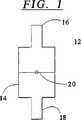
図1は、本発明のバルブ組立体を通る長手方向の断面の概略図を示す。
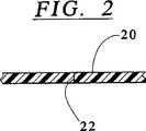
図2は、図1の円で囲んだ領域の拡大図である。
図3は、圧力を加えた状態の図1のバルブ組立体を示す。
図4は、図3の円で囲んだ領域の拡大図である。
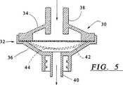
図5は、流体を両方向に移送することができる本発明の実施例の長手方向の断面図である。
図6は、流体を一方向にだけ移送することができる本発明の他の実施例のバルブを通る長手方向の断面図である。
図7は、弾性膜を緊張させて穴を開口させるために弾性膜を手で撓ませることのできるようにする手段を含む本発明の他の実施例のバルブを通る長手方向の断面図である。
図8は、手で力を加えた後の図7バルブ組立体を通る長手方向の断面図である。
図9は、突き通し部材を含む本発明の他の実施例のバルブ組立体を通る長手方向の断面図である。
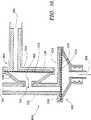
図10は、二方向バルブを構成する本発明のさらに他の実施例のバルブ組立体を通る長手方向の断面図である。
好ましい実施例の詳細な説明
本発明のバルブ組立体の概略図を示す図1〜図4をまず参照する。このバルブ組立体12は液体入口16および液体出口18を有する本体14を含む。(この実施例に関して「出口」および「入口」という用語を使用しているのは、実際のところ、認識されるように単に便宜的なことである。ここに示すバルブは対称的なもので、入口および出口の機能は逆にすることができる。)入口16および出口18の間にはそれらの入口および出口を隔離する弾性膜20が配置されており、この弾性膜は例えばシリコーンゴムで作られる。図2に見られるように、弾性膜20には穴22が形成されており、この穴は、弾性膜の両側間に圧力差が存在していない状態では穴の壁面が圧潰されて、穴が完全に塞がれる位置にある。
液体圧力が入口16を通して作用されると(図3に矢印で概略的に示されている)、弾性膜20は変形し緊張し、これによりその穴が拡張して図4に見られるように流体を通過させることができる開かれた穴を形成する。
本発明の実施例のバルブ組立体30を示す図5を参照する。このバルブ組立体は互いに係合された二つの部材34,36で構成されたハウジング32を含む。部材34は流体入口38を形成し、また部材36は流体出口40を形成しており、この実施例では出口40はルアー形式(luer-type)コネクタである。膜42が入口および出口の間に配置され、部材34,36の連結箇所によって所定位置に保持される。
膜42は穴を有しており、この穴は図5に示される係止状態においては塞がれすなわち閉じられている。膜に液体圧力が作用されると膜は変形し(点線で照明されている)、穴44が開いて流体の通過を可能にする。図1〜図4のバルブ組立体の場合と同様に、液体は基本的にはいずれの方向にも流れることもでき、この流れは付与された流体の方向によって決まる(ここで再び説明するが、部材38,40)はそれぞれ便宜的に「入口」および「出口」と定められており、入口38から出口40へ向かう流れ方向は好ましい方向とされる。)
液体の流れが一方向にだけ可能とされる他の実施例のバルブ組立体50を示す図6を参照する。このバルブ組立体50はそれぞれ入口58および出口60を形成している第1部材54および第2部材56で構成されたハウジング52を含み、出口60はルアー形式(luer-type)コネクタである。ケーシングすなわちハウジング52の内部には弾性膜62が配置され、部材54,56の連結部分の間に保持されている。図示されるように、部材54は弾性膜62に平行に配置された壁部64を有しており、したがってこの弾性膜は壁部64と反対方向(出口60へ向かう方向)にだけ変形することができる。入口58から与えられた(矢印で示される)液体圧力が或る閾値を超えると、膜が変形して(変形した部材が点線で示されている)元々存在している膜の穴66が開かれて、入口58と出口60との間で流体が流れるようにする。
他の実施例のバルブ組立体70を示す図7および図8を参照する。この実施例と図6に示した実施例との違いは第一部材74にあり、図6と同じ符号を与えられている他のすべての部材は実際に同じ機能を果たす。部材74は入口82を形成する中央部分80、および膜62に接近して位置される環状膨み部分84とを有する。中央部分80は部材74の周辺部分86に対して中間可撓ショルダ部分88により連結され、この可撓ショルダ部分88が中央部分82と周辺部分86との相対的な軸線方向に沿う動きを可能にしている。
中央部分が周辺部分に対して移動して、図8に見られるように膜62を押圧すると、膜は変形し、穴66が開いて液体が流れ得るようになり、この実施例の組立体は本質的に図6の組立体と同じように作動する、すなわち一方向の液体流れのみ可能にする。
本発明の他の実施例のバルブ組立体90を示す図9を参照する。この実施例は図5に示された実施例の変更例であり、すべての部材は同じ符号を与えられている。これら二つの実施例の違いは、組立体90が突き通し部材92を有すること、また本実施例のショルダ94は幾分かの可撓性を有することにある。したがって、部材34の中央部分96は膜42へ向かって僅かに押圧され、突き通し部材92がこれにより膜に穴を開ける。この穴は休止時は密閉されるのであり、膜の両側間に圧力差が与えられたときに開く。
認識されるように、突き通し部材92は管腔を有して内部に液体を流すようにすることができる。この代わりに、液体が突き通し部材の周囲空間98を流れるようにすることができる。
全体を符号100で示される二方向バルブを示す図10に注目する。この二方向バルブはバルブ102,104で構成されており、これらのバルブはこの特定実施例においては上述で説明したように図6に示されたバルブと同じである。
第一バルブ102は一方向バルブで矢印106の方向にだけ流れを可能にし、第二バルブ104は一方向バルブで矢印108の方向にだけ流れを可能にする。第二バルブ104の流体出口110は第一バルブ102の流体入口チューブ112に取付けられ、この入口チューブ112は自由端部114を有しており、またバルブ104は流体入口115を含む。
この構成は二方向バルブ100が三つの作動状態を有するようにさせる。第一の状態では、流体は自由端部114および入口116の両方を通して流入する。また上述した図6の実施例に関連して説明したように、液体圧力が或る閾値を超えると、第一バルブ102の膜118は変形し、元々存在している膜の穴(見ることはできない)を通って流体が出口106から流出できるようにする。
第二の作動状態では、流体は自由端部114だけを通して流入し、第二バルブ104の膜120は一方向バルブとして作用するので、流体は第一バルブ部材102の出口106だけを通って流出する。
第三の作動状態は、流体が第二バルブ104の流体入口116だけを通して流入し、膜118を変形させるのに必要な圧力が本質的に高い圧力であるために自由端部114だけを通して流出するときに生じる。
しかしながら、図10のバルブ組立体の特定の応用例として、例えば患者に対する給送装置があり、これにおいては給送チューブは第一バルブ102の出口に連結されて患者へ導かれる。第一液体栄養容器(図示せず)がポンプ(ポンプ自体は周知であるので図示されない)を経て第二バルブ組立体104の入口116に連結される。第一作動モードにおいて、ポンプが第二液体容器から液体を入口チューブ112へ圧送し、これにより液体は第一バルブ組立体102を通して圧送されるが、第二バルブ組立体104を通過することはできない。第二作動モードにおいて、このポンプが逆方向に作動され、これにより所定量の液体が第一液体容器から、第二液体容器に通じた管路へ吸入され、その後ポンプは再び作動を逆転されて前記所定量の液体が上述で説明したように第一バルブ組立体102を通して圧送される。このようにして二つの容器のいずれか一方からの液体、例えば栄養剤、および水すなわち洗浄剤が患者に対して交互に供給されることができる。
また図10には突起122と、バルブ組立体の後壁124から突出している環状突起126とが見られ、膜118および120がバルブ組立体102,104のそれぞれの後壁124に接着しないことを保証し、またこれらの弾性膜が逆方向(すなわちバルブ部の入口に向かう)に変形せずに一方向のみの流れを確保することを保証している。Background of the invention The present invention relates to a valve assembly for liquid transfer.
SUMMARY OF THE INVENTION In accordance with the present invention, a liquid inlet, a liquid outlet, and a valve member disposed between the liquid inlet and the liquid outlet, the valve member isolates the liquid inlet and the liquid outlet. The elastic membrane has one or more holes, and in the state where there is no pressure difference between both sides of the elastic membrane, the wall surface of the one or more holes is crushed and the liquid does not have any holes. For liquid transport that cannot pass through and at one threshold level elastic membrane tension opens one or more holes and allows liquid to flow from one side of the elastic membrane to the other through the hole A valve assembly is provided.
According to an embodiment of the present invention, the valve is a one-way type valve that can transfer fluid in only one direction.
According to another embodiment of the present invention, the valve assembly includes an auxiliary member that allows the elastic membrane to be manually pulled to open one or more holes.
The pressure threshold is determined by the thickness and surface area of the elastic membrane and the dimensions of the one or more holes.
According to yet another embodiment of the invention, the valve assembly includes a piercing member for piercing the elastic membrane so as to form at least one hole of the type defined above.
According to another aspect of the present invention, the first valve assembly and the second valve assembly each selected independently (separately) from the group comprising valve assemblies according to any of the preceding claims, A fluid valve assembly is provided in which a liquid outlet of a second valve assembly is in communication with a liquid outlet of the first valve assembly.
The present invention will be described in the following specific, non-limiting examples, particularly with reference to the accompanying drawings.
[Brief description of the drawings]
FIG. 1 shows a schematic diagram of a longitudinal section through the valve assembly of the present invention.
FIG. 2 is an enlarged view of a region surrounded by a circle in FIG.
FIG. 3 shows the valve assembly of FIG. 1 under pressure.
FIG. 4 is an enlarged view of a region surrounded by a circle in FIG.
FIG. 5 is a longitudinal cross-sectional view of an embodiment of the present invention capable of transferring fluid in both directions.
FIG. 6 is a longitudinal cross-sectional view through a valve of another embodiment of the invention capable of transporting fluid in only one direction.
FIG. 7 is a longitudinal cross-sectional view through a valve of another embodiment of the present invention including means for allowing the elastic membrane to be deflected manually to tension the elastic membrane and open the hole. .
FIG. 8 is a longitudinal cross-sectional view through the valve assembly of FIG. 7 after manual force is applied.
FIG. 9 is a longitudinal cross-sectional view through a valve assembly of another embodiment of the invention including a piercing member.
FIG. 10 is a longitudinal cross-sectional view through a valve assembly of yet another embodiment of the present invention that constitutes a two-way valve.
Detailed Description of the Preferred Embodiment Reference is first made to FIGS. 1-4 which show schematic views of the valve assembly of the present invention. The
When liquid pressure is applied through the inlet 16 (represented schematically by an arrow in FIG. 3), the
Reference is made to FIG. 5 showing a
The
Reference is made to FIG. 6 showing another
Reference is made to FIGS. 7 and 8 illustrating another
When the central portion moves relative to the peripheral portion and presses against the
Reference is made to FIG. 9 showing a
As will be appreciated, the
Attention is now directed to FIG. 10, which shows a two-way valve, generally designated 100. This two-way valve is composed of
The
This configuration allows the two-
In the second operating state, fluid flows only through the
The third operating condition is that fluid flows only through the
However, a particular application of the valve assembly of FIG. 10 is, for example, a delivery device for a patient, in which the delivery tube is connected to the outlet of the
Also seen in FIG. 10 is a
Claims (3)
Translated fromJapanese第1バルブ組立体(102)および第2バルブ組立体(104)と、A first valve assembly (102) and a second valve assembly (104);
第1バルブ組立体(102)が液体入口(112)と、液体出口(106)と、これら液体入口(112)および液体出口(106)の間に配置したバルブ部材とを有し、該バルブ部材が液体入口(112)および液体出口(106)の間を隔てる弾性膜(118)を含むことと、The first valve assembly (102) has a liquid inlet (112), a liquid outlet (106), and a valve member disposed between the liquid inlet (112) and the liquid outlet (106), the valve member Including an elastic membrane (118) separating the liquid inlet (112) and the liquid outlet (106);
第2バルブ組立体(104)が液体入口(116)と、液体出口(110)と、これら液体入口(116)および液体出口(110)の間に配置したバルブ部材とを有し、該バルブ部材が液体入口(116)および液体出口(110)の間を隔てる弾性膜(120)を含むことと、A second valve assembly (104) has a liquid inlet (116), a liquid outlet (110), and a valve member disposed between the liquid inlet (116) and the liquid outlet (110), the valve member Including an elastic membrane (120) separating the liquid inlet (116) and the liquid outlet (110);
第1バルブ組立体(102)および第2バルブ組立体(104)の弾性膜が一つ以上の穴を備え、各弾性膜の2つの側の間に圧力差が無い状態では、この一つ以上の穴の壁面が圧潰されて液体は該穴を通過できず、また各弾性膜の2つの側面間の圧力差が或る閾値レベルを超えた状態では、該弾性膜の伸張が一つ以上の穴を開口させて、液体を該弾性膜の一方の側から他方の側へ通すことと、In the state where the elastic membranes of the first valve assembly (102) and the second valve assembly (104) have one or more holes and there is no pressure difference between the two sides of each elastic membrane, one or more of these. When the wall surface of the hole is crushed and liquid cannot pass through the hole, and the pressure difference between the two side surfaces of each elastic membrane exceeds a certain threshold level, the elastic membrane stretches to one or more. Opening a hole and passing liquid from one side of the elastic membrane to the other;
第1バルブ組立体(102)および第2バルブ組立体(104)内で各弾性膜の入口側と前記バルブ部材の内壁との間に設けた突起(122,126)であって、液体入口の方向への弾性膜の変形を防いで液体出口の方向へのみ液体を通過させる突起と、Protrusions (122, 126) provided between the inlet side of each elastic membrane and the inner wall of the valve member in the first valve assembly (102) and the second valve assembly (104), A protrusion that prevents the deformation of the elastic film in the direction and allows the liquid to pass only in the direction of the liquid outlet;
第2バルブ組立体(104)の液体出口(110)と第1バルブ組立体(102)の液体入口(112)の間を流れ連通させることと、Flow communication between the liquid outlet (110) of the second valve assembly (104) and the liquid inlet (112) of the first valve assembly (102);
第1バルブ組立体(102)の液体入口(112)がバルブ組立体装置(100)へ液体を流入させる端部を備え、第2バルブ組立体(104)の液体入口(116)もバルブ組立体装置(100)へ液体を流入させることと、The liquid inlet (112) of the first valve assembly (102) has an end that allows liquid to flow into the valve assembly apparatus (100), and the liquid inlet (116) of the second valve assembly (104) is also the valve assembly. Flowing liquid into the device (100);
第1バルブ組立体(102)の液体出口(106)がバルブ組立体装置(100)から液体を流れ出させることと、A liquid outlet (106) of the first valve assembly (102) causes liquid to flow out of the valve assembly device (100);
第1液体容器および第2液体容器と、A first liquid container and a second liquid container;
ポンプであって、該ポンプは、第2液体容器から第1バルブ組立体(102)の液体入口(112)へ液体を給送し、これによって液体が第1バルブ組立体(102)を押し通るものの第2バルブ組立体(104)を通り得ない第1作動モードを備えるポンプと、A pump, which pumps liquid from a second liquid container to a liquid inlet (112) of the first valve assembly (102), thereby pushing the liquid through the first valve assembly (102). A pump with a first mode of operation that cannot pass through the second valve assembly (104) of the object;
このポンプは、逆方向に作動し、これによって第1液体容器から所定量の液体が第2液体容器へ至る管路内に吸い込まれる第2作動モードを備えることと、The pump operates in the reverse direction, thereby providing a second mode of operation in which a predetermined amount of liquid is drawn from the first liquid container into the conduit leading to the second liquid container;
該ポンプが続いて作動方向を逆転して再び第1作動モードに入ると、この所定量の液体が第1バルブ組立体(102)を介して加圧されることとを含む、バルブ組立体装置。A valve assembly apparatus comprising: pressurizing the predetermined amount of liquid through the first valve assembly (102) when the pump subsequently reverses the direction of operation and enters the first mode of operation again. .
Applications Claiming Priority (3)
| Application Number | Priority Date | Filing Date | Title |
|---|---|---|---|
| IL114190 | 1995-06-16 | ||
| IL11419095AIL114190A (en) | 1995-06-16 | 1995-06-16 | Valve assembly |
| PCT/IB1996/001007WO1997000399A2 (en) | 1995-06-16 | 1996-06-07 | Valve assembly |
Publications (2)
| Publication Number | Publication Date |
|---|---|
| JPH11508346A JPH11508346A (en) | 1999-07-21 |
| JP3756189B2true JP3756189B2 (en) | 2006-03-15 |
Family
ID=11067628
Family Applications (1)
| Application Number | Title | Priority Date | Filing Date |
|---|---|---|---|
| JP50236097AExpired - Fee RelatedJP3756189B2 (en) | 1995-06-16 | 1996-06-07 | Valve assembly |
Country Status (13)
| Country | Link |
|---|---|
| US (1) | US6182698B1 (en) |
| EP (1) | EP0830533B1 (en) |
| JP (1) | JP3756189B2 (en) |
| CN (1) | CN1117236C (en) |
| AT (1) | ATE279674T1 (en) |
| AU (1) | AU707529B2 (en) |
| CA (1) | CA2219499C (en) |
| DE (1) | DE69633622T2 (en) |
| DK (1) | DK0830533T3 (en) |
| ES (1) | ES2229283T3 (en) |
| IL (2) | IL114190A (en) |
| PT (1) | PT830533E (en) |
| WO (1) | WO1997000399A2 (en) |
Families Citing this family (44)
| Publication number | Priority date | Publication date | Assignee | Title |
|---|---|---|---|---|
| IL123227A0 (en)* | 1998-02-08 | 1998-09-24 | 3By Ltd | Check valve |
| IL146886A0 (en) | 1999-06-05 | 2002-08-14 | Innovata Biomed Ltd | Medicament delivery system |
| GB9920839D0 (en) | 1999-09-04 | 1999-11-10 | Innovata Biomed Ltd | Inhaler |
| GB0016478D0 (en)* | 2000-07-05 | 2000-08-23 | Innovata Biomed Ltd | Valve |
| DE10045666C1 (en)* | 2000-09-15 | 2002-06-13 | Bosch Gmbh Robert | Dosing unit for measuring small amounts of liquid |
| US7331944B2 (en)* | 2000-10-23 | 2008-02-19 | Medical Instill Technologies, Inc. | Ophthalmic dispenser and associated method |
| CA2426182C (en) | 2000-10-23 | 2007-03-13 | Py Patent, Inc. | Fluid dispenser having a housing and flexible inner bladder |
| US7798185B2 (en) | 2005-08-01 | 2010-09-21 | Medical Instill Technologies, Inc. | Dispenser and method for storing and dispensing sterile food product |
| GB0128148D0 (en) | 2001-11-23 | 2002-01-16 | Innovata Biomed Ltd | Assembly |
| EP2272422B1 (en)* | 2001-12-07 | 2016-05-04 | ACIST Medical Systems, Inc. | Fluid valve which blocks output by high pressure input |
| EP1546021B1 (en)* | 2002-08-13 | 2010-10-20 | Medical Instill Technologies, Inc. | Container and valve assembly for storing and dispensing substances, and related method |
| US6957744B2 (en)* | 2003-01-24 | 2005-10-25 | Insta-Mix, Inc. | Nipple with multiple pinholes for baby bottle assembly |
| US6997219B2 (en) | 2003-05-12 | 2006-02-14 | Medical Instill Technologies, Inc. | Dispenser and apparatus and method for filling a dispenser |
| US7226231B2 (en) | 2003-07-17 | 2007-06-05 | Medical Instill Technologies, Inc. | Piston-type dispenser with one-way valve for storing and dispensing metered amounts of substances |
| US7264142B2 (en) | 2004-01-27 | 2007-09-04 | Medical Instill Technologies, Inc. | Dispenser having variable-volume storage chamber and depressible one-way valve assembly for dispensing creams and other substances |
| CA2562386C (en) | 2004-04-21 | 2014-11-18 | Innovata Biomed Limited | Inhaler |
| EP1817237A4 (en)* | 2004-12-04 | 2016-08-31 | Medical Instill Tech Inc | One-way valve, apparatus and method of using the valve |
| US7810677B2 (en)* | 2004-12-04 | 2010-10-12 | Medical Instill Technologies, Inc. | One-way valve and apparatus and method of using the valve |
| US7896859B2 (en)* | 2005-10-20 | 2011-03-01 | Tyco Healthcare Group Lp | Enteral feeding set |
| US7611502B2 (en) | 2005-10-20 | 2009-11-03 | Covidien Ag | Connector for enteral fluid delivery set |
| CA2654090C (en)* | 2006-06-14 | 2013-02-05 | Acist Medical Systems, Inc. | Fluid purge in a medical injection system |
| CN101583542B (en)* | 2006-09-08 | 2013-07-10 | 因斯蒂尔医学技术有限公司 | Apparatus and method for dispensing fluids |
| DE102007039753B4 (en)* | 2007-08-17 | 2017-12-21 | Hanon Systems | Refrigerant accumulator for motor vehicle air conditioners |
| AU2011249932B2 (en) | 2010-05-07 | 2015-12-17 | Alps, Llc | Dispensing machine valve and method |
| DE102011075518A1 (en)* | 2010-09-02 | 2012-04-26 | Robert Bosch Gmbh | Arrangement for throttling a fluid flow and corresponding piston pump for conveying fluids |
| CN102553032A (en)* | 2011-12-19 | 2012-07-11 | 吴林元 | Automatic air exhaust valve device for transfusion |
| US9085399B2 (en)* | 2012-05-21 | 2015-07-21 | The Coca-Cola Company | Bag in box cleanable connector system |
| WO2013177527A1 (en) | 2012-05-25 | 2013-11-28 | Acist Medical Systems, Inc. | Fluid flow measurement systems and methods |
| CN105268034A (en)* | 2014-06-12 | 2016-01-27 | 江苏瑞京科技发展有限公司 | Counter current preventing device of drainage device |
| US9539452B2 (en)* | 2014-07-11 | 2017-01-10 | Kidde Technologies, Inc. | Rapid pressure diffusion actuator for a fire extinguisher |
| US9821183B2 (en) | 2014-07-11 | 2017-11-21 | Kidde Technologies, Inc. | Motorized actuator for a fire extinguisher |
| US9649520B2 (en)* | 2014-07-11 | 2017-05-16 | Kidde Technologies, Inc. | Burst disc puncture pressure-imbalance actuator for a fire extinguisher |
| AU2016282741A1 (en)* | 2015-06-22 | 2017-11-02 | Société des Produits Nestlé S.A. | Self-aerating valve |
| CN106763940B (en)* | 2016-11-11 | 2019-10-11 | 江苏桑力太阳能产业有限公司 | A kind of thermal-collecting tube cutout valve |
| CN110573777B (en)* | 2017-04-28 | 2022-04-26 | 日东电工株式会社 | ventilation unit |
| TW201920866A (en)* | 2017-08-21 | 2019-06-01 | 日商普利司通股份有限公司 | Check valve, manufacturing method of check valve, check valve assembly and manufacturing method of check valve assembly capable of achieving small variations of an opening of a valve part and facilitating the manufacturing process |
| CN107962044B (en)* | 2018-01-10 | 2023-05-23 | 江苏省人民医院(南京医科大学第一附属医院) | Nasal intestinal canal blockage flushing device and flushing method thereof |
| JP7348916B2 (en) | 2018-05-23 | 2023-09-21 | アシスト・メディカル・システムズ,インコーポレイテッド | Flow measurement using image data |
| CN108730574A (en)* | 2018-05-29 | 2018-11-02 | 芜湖澳奔玛汽车部件有限公司 | A kind of pressure valve for air cleaner |
| CN111228884B (en)* | 2020-01-15 | 2020-11-17 | 浙江省海洋水产研究所 | Manual extraction element of micro plastic granules |
| CN114275727A (en)* | 2020-06-24 | 2022-04-05 | 中山市华宝勒生活用品实业有限公司 | Liquid pumping device |
| US11633534B2 (en) | 2020-08-18 | 2023-04-25 | Acist Medical Systems, Inc. | Angiogram injections using electrocardiographic synchronization |
| CN114680598B (en)* | 2020-12-31 | 2024-04-16 | 佛山市顺德区美的电热电器制造有限公司 | Cooking container and cooking utensil |
| EP4173962B1 (en)* | 2021-10-27 | 2025-09-03 | Airbus Operations (S.A.S.) | Enclosure containing an inerting gas and comprising a liquid discharge system, aircraft comprising such an enclosure |
Family Cites Families (21)
| Publication number | Priority date | Publication date | Assignee | Title |
|---|---|---|---|---|
| FR583437A (en)* | 1924-07-07 | 1925-01-13 | Safety valve for holders of gas or other pressurized fluids | |
| US2908283A (en)* | 1955-07-11 | 1959-10-13 | Chamberlain Corp | Disc valve and assembly |
| US3119411A (en)* | 1957-12-21 | 1964-01-28 | Rau Swf Autozubehoer | Valved t-pipe joint, particularly for windshield washing apparatus |
| GB1199498A (en) | 1967-03-29 | 1970-07-22 | Latex Products Proprietary Ltd | Non-Return Valve for Medical Uses. |
| US3710942A (en) | 1967-06-02 | 1973-01-16 | Pall Corp | Valve for fluid lines and structures containing the same |
| US3485419A (en)* | 1968-01-30 | 1969-12-23 | Wilfred V Taylor | Fluent material dispenser |
| US3496874A (en)* | 1968-04-16 | 1970-02-24 | John S Findlay | Diaphragm actuated pulse pump |
| US3599657A (en)* | 1969-04-07 | 1971-08-17 | Bruning Co | Double diaphram check valve |
| FR2265022B1 (en) | 1974-03-21 | 1977-08-19 | Duveau Francois | |
| US4100930A (en) | 1976-05-03 | 1978-07-18 | Texas Instruments Incorporated | Pressure relief valve |
| US4246932A (en)* | 1979-10-18 | 1981-01-27 | Burron Medical, Inc. | Multiple additive valve assembly |
| US4583981A (en) | 1981-11-27 | 1986-04-22 | Alza Corporation | Parenteral controlled therapy, using a porous matrix with parenteral agent |
| US4666429A (en) | 1986-02-26 | 1987-05-19 | Intelligent Medicine, Inc. | Infusion device having improved valving apparatus |
| FR2608720B1 (en) | 1986-12-18 | 1989-03-03 | Electricite De France | MEMBRANE SAFETY DEVICE WITH ACTIVE UPSTREAM BLADE KNIFE |
| US4729401A (en)* | 1987-01-29 | 1988-03-08 | Burron Medical Inc. | Aspiration assembly having dual co-axial check valves |
| US4915688A (en) | 1987-12-03 | 1990-04-10 | Baxter International Inc. | Apparatus for administering solution to a patient |
| US5037390A (en) | 1989-12-28 | 1991-08-06 | Kenneth Raines | System and method for mixing parenteral nutrition solutions |
| US5273546A (en)* | 1991-08-01 | 1993-12-28 | Medtronic, Inc. | Hemostasis valve |
| US5230706A (en) | 1992-03-12 | 1993-07-27 | Duquette Irene A | Bi-directional valve assembly used in needleless injection or infusion ports |
| US5269771A (en)* | 1993-02-24 | 1993-12-14 | Thomas Medical Products, Inc. | Needleless introducer with hemostatic valve |
| US5279557A (en) | 1993-05-24 | 1994-01-18 | Lomick Joe B | Multiple chamber IV delivery device |
- 1995
- 1995-06-16ILIL11419095Apatent/IL114190A/ennot_activeIP Right Cessation
- 1995-06-16ILIL12588195Apatent/IL125881A/ennot_activeIP Right Cessation
- 1996
- 1996-06-07PTPT96930314Tpatent/PT830533E/enunknown
- 1996-06-07DKDK96930314Tpatent/DK0830533T3/enactive
- 1996-06-07CACA002219499Apatent/CA2219499C/ennot_activeExpired - Fee Related
- 1996-06-07AUAU69412/96Apatent/AU707529B2/ennot_activeCeased
- 1996-06-07WOPCT/IB1996/001007patent/WO1997000399A2/enactiveIP Right Grant
- 1996-06-07ESES96930314Tpatent/ES2229283T3/ennot_activeExpired - Lifetime
- 1996-06-07JPJP50236097Apatent/JP3756189B2/ennot_activeExpired - Fee Related
- 1996-06-07EPEP96930314Apatent/EP0830533B1/ennot_activeExpired - Lifetime
- 1996-06-07CNCN96194568Apatent/CN1117236C/ennot_activeExpired - Fee Related
- 1996-06-07USUS08/930,073patent/US6182698B1/ennot_activeExpired - Fee Related
- 1996-06-07DEDE69633622Tpatent/DE69633622T2/ennot_activeExpired - Lifetime
- 1996-06-07ATAT96930314Tpatent/ATE279674T1/enactive
Also Published As
| Publication number | Publication date |
|---|---|
| PT830533E (en) | 2005-01-31 |
| DK0830533T3 (en) | 2004-12-20 |
| CN1189208A (en) | 1998-07-29 |
| IL114190A0 (en) | 1995-10-31 |
| ES2229283T3 (en) | 2005-04-16 |
| ATE279674T1 (en) | 2004-10-15 |
| WO1997000399A2 (en) | 1997-01-03 |
| JPH11508346A (en) | 1999-07-21 |
| CA2219499C (en) | 2006-05-30 |
| US6182698B1 (en) | 2001-02-06 |
| IL114190A (en) | 1999-08-17 |
| CA2219499A1 (en) | 1997-01-03 |
| WO1997000399A3 (en) | 1997-06-12 |
| AU707529B2 (en) | 1999-07-15 |
| EP0830533A4 (en) | 1998-07-22 |
| DE69633622D1 (en) | 2004-11-18 |
| IL125881A (en) | 2001-04-30 |
| DE69633622T2 (en) | 2005-11-03 |
| AU6941296A (en) | 1997-01-15 |
| EP0830533A2 (en) | 1998-03-25 |
| EP0830533B1 (en) | 2004-10-13 |
| CN1117236C (en) | 2003-08-06 |
Similar Documents
| Publication | Publication Date | Title |
|---|---|---|
| JP3756189B2 (en) | Valve assembly | |
| KR100708492B1 (en) | Non-Return Valve | |
| US4191204A (en) | Pressure responsive fluid collection system | |
| US6036171A (en) | Swabbable valve assembly | |
| US5653251A (en) | Vacuum actuated sheath valve | |
| US6102361A (en) | Fluidic pinch valve system | |
| US6708950B2 (en) | Bite valve | |
| RU99100056A (en) | DROPPER, PUMPING SYSTEM AND METHOD FOR SEQUENTIAL DELIVERY OF TWO LIQUIDS FROM A PAIR OF CONTAINERS TO A PATIENT | |
| US7628590B2 (en) | Method and apparatus for reducing free flow risk | |
| US12150911B2 (en) | Air connection piping device for a massage pool, a pool body of a massage pool and a massage pool | |
| CN101349356A (en) | One-way elastic valve and fluid delivery device used thereby | |
| CA2020927A1 (en) | Multiline check valve assembly | |
| CN108452434B (en) | Multiple unidirectional airtight joint and pipeline device | |
| CN113855561A (en) | Low starting force self-sealing puncture outfit | |
| GB2280489A (en) | A non-return valve | |
| CN217679459U (en) | Closestool flushing system and pressure device thereof | |
| US20210270379A1 (en) | Fluid system | |
| EP4545161A1 (en) | Degassing device | |
| CN111255913B (en) | A flexible flow cut-off device | |
| JP2554739Y2 (en) | Check valve structure for vehicles | |
| AU775326B2 (en) | A non-return valve | |
| WO2023238139A1 (en) | Normally closed valve assembly and valve system | |
| CN2180850Y (en) | Membrane type fluid return-proof device | |
| US20020130293A1 (en) | Deformable membrane valve apparatus and method | |
| JPH0856899A (en) | Check valve structure and endoscope equipped with this structure |
Legal Events
| Date | Code | Title | Description |
|---|---|---|---|
| A131 | Notification of reasons for refusal | Free format text:JAPANESE INTERMEDIATE CODE: A131 Effective date:20050405 | |
| A601 | Written request for extension of time | Free format text:JAPANESE INTERMEDIATE CODE: A601 Effective date:20050705 | |
| A602 | Written permission of extension of time | Free format text:JAPANESE INTERMEDIATE CODE: A602 Effective date:20050822 | |
| A521 | Request for written amendment filed | Free format text:JAPANESE INTERMEDIATE CODE: A523 Effective date:20051005 | |
| TRDD | Decision of grant or rejection written | ||
| A01 | Written decision to grant a patent or to grant a registration (utility model) | Free format text:JAPANESE INTERMEDIATE CODE: A01 Effective date:20051213 | |
| A61 | First payment of annual fees (during grant procedure) | Free format text:JAPANESE INTERMEDIATE CODE: A61 Effective date:20051221 | |
| R150 | Certificate of patent or registration of utility model | Free format text:JAPANESE INTERMEDIATE CODE: R150 | |
| FPAY | Renewal fee payment (event date is renewal date of database) | Free format text:PAYMENT UNTIL: 20100106 Year of fee payment:4 | |
| FPAY | Renewal fee payment (event date is renewal date of database) | Free format text:PAYMENT UNTIL: 20110106 Year of fee payment:5 | |
| FPAY | Renewal fee payment (event date is renewal date of database) | Free format text:PAYMENT UNTIL: 20120106 Year of fee payment:6 | |
| FPAY | Renewal fee payment (event date is renewal date of database) | Free format text:PAYMENT UNTIL: 20130106 Year of fee payment:7 | |
| LAPS | Cancellation because of no payment of annual fees |