JP3756185B2 - Stent placement device with dosing device and method thereof - Google Patents
Stent placement device with dosing device and method thereofDownload PDFInfo
- Publication number
- JP3756185B2 JP3756185B2JP51998796AJP51998796AJP3756185B2JP 3756185 B2JP3756185 B2JP 3756185B2JP 51998796 AJP51998796 AJP 51998796AJP 51998796 AJP51998796 AJP 51998796AJP 3756185 B2JP3756185 B2JP 3756185B2
- Authority
- JP
- Japan
- Prior art keywords
- balloon
- stent
- diameter
- conduit
- inflation
- Prior art date
- Legal status (The legal status is an assumption and is not a legal conclusion. Google has not performed a legal analysis and makes no representation as to the accuracy of the status listed.)
- Expired - Fee Related
Links
- 238000000034methodMethods0.000titleclaimsdescription10
- 239000003814drugSubstances0.000claimsdescription24
- 229940079593drugDrugs0.000claimsdescription19
- 239000012530fluidSubstances0.000claimsdescription19
- 238000012377drug deliveryMethods0.000claimsdescription13
- 238000004891communicationMethods0.000claimsdescription6
- 238000004519manufacturing processMethods0.000claimsdescription6
- 238000003780insertionMethods0.000claimsdescription5
- 230000037431insertionEffects0.000claimsdescription5
- -1polyethylene terephthalatePolymers0.000claimsdescription4
- 239000002861polymer materialSubstances0.000claimsdescription4
- 239000004698PolyethyleneSubstances0.000claimsdescription2
- 229920000573polyethylenePolymers0.000claimsdescription2
- 229920000139polyethylene terephthalatePolymers0.000claimsdescription2
- 239000005020polyethylene terephthalateSubstances0.000claimsdescription2
- 229920000642polymerPolymers0.000claimsdescription2
- 230000002792vascularEffects0.000claims3
- 210000004204blood vesselAnatomy0.000claims1
- 238000005553drillingMethods0.000claims1
- 239000000284extractSubstances0.000claims1
- 239000007943implantSubstances0.000description7
- 238000002513implantationMethods0.000description5
- 210000001367arteryAnatomy0.000description4
- 239000000463materialSubstances0.000description4
- 208000031481Pathologic ConstrictionDiseases0.000description3
- 208000037804stenosisDiseases0.000description3
- 230000036262stenosisEffects0.000description3
- 239000000126substanceSubstances0.000description3
- 230000003143atherosclerotic effectEffects0.000description2
- 230000003902lesionEffects0.000description2
- 238000004026adhesive bondingMethods0.000description1
- 208000007474aortic aneurysmDiseases0.000description1
- 238000003491arrayMethods0.000description1
- 230000008602contractionEffects0.000description1
- 208000029078coronary artery diseaseDiseases0.000description1
- 239000008187granular materialSubstances0.000description1
- 230000001678irradiating effectEffects0.000description1
- 239000007788liquidSubstances0.000description1
- 229910052751metalInorganic materials0.000description1
- 239000002184metalSubstances0.000description1
- 150000002739metalsChemical class0.000description1
- 238000012986modificationMethods0.000description1
- 230000004048modificationEffects0.000description1
- 239000000523sampleSubstances0.000description1
- 238000007789sealingMethods0.000description1
- 238000002054transplantationMethods0.000description1
- 239000011345viscous materialSubstances0.000description1
- 238000004804windingMethods0.000description1
Images


Classifications
- A—HUMAN NECESSITIES
- A61—MEDICAL OR VETERINARY SCIENCE; HYGIENE
- A61F—FILTERS IMPLANTABLE INTO BLOOD VESSELS; PROSTHESES; DEVICES PROVIDING PATENCY TO, OR PREVENTING COLLAPSING OF, TUBULAR STRUCTURES OF THE BODY, e.g. STENTS; ORTHOPAEDIC, NURSING OR CONTRACEPTIVE DEVICES; FOMENTATION; TREATMENT OR PROTECTION OF EYES OR EARS; BANDAGES, DRESSINGS OR ABSORBENT PADS; FIRST-AID KITS
- A61F2/00—Filters implantable into blood vessels; Prostheses, i.e. artificial substitutes or replacements for parts of the body; Appliances for connecting them with the body; Devices providing patency to, or preventing collapsing of, tubular structures of the body, e.g. stents
- A61F2/95—Instruments specially adapted for placement or removal of stents or stent-grafts
- A61F2/958—Inflatable balloons for placing stents or stent-grafts
- A—HUMAN NECESSITIES
- A61—MEDICAL OR VETERINARY SCIENCE; HYGIENE
- A61M—DEVICES FOR INTRODUCING MEDIA INTO, OR ONTO, THE BODY; DEVICES FOR TRANSDUCING BODY MEDIA OR FOR TAKING MEDIA FROM THE BODY; DEVICES FOR PRODUCING OR ENDING SLEEP OR STUPOR
- A61M25/00—Catheters; Hollow probes
- A61M25/0021—Catheters; Hollow probes characterised by the form of the tubing
- A61M25/0023—Catheters; Hollow probes characterised by the form of the tubing by the form of the lumen, e.g. cross-section, variable diameter
- A—HUMAN NECESSITIES
- A61—MEDICAL OR VETERINARY SCIENCE; HYGIENE
- A61M—DEVICES FOR INTRODUCING MEDIA INTO, OR ONTO, THE BODY; DEVICES FOR TRANSDUCING BODY MEDIA OR FOR TAKING MEDIA FROM THE BODY; DEVICES FOR PRODUCING OR ENDING SLEEP OR STUPOR
- A61M25/00—Catheters; Hollow probes
- A61M25/10—Balloon catheters
- A61M25/1027—Making of balloon catheters
- A61M25/1029—Production methods of the balloon members, e.g. blow-moulding, extruding, deposition or by wrapping a plurality of layers of balloon material around a mandril
- A—HUMAN NECESSITIES
- A61—MEDICAL OR VETERINARY SCIENCE; HYGIENE
- A61F—FILTERS IMPLANTABLE INTO BLOOD VESSELS; PROSTHESES; DEVICES PROVIDING PATENCY TO, OR PREVENTING COLLAPSING OF, TUBULAR STRUCTURES OF THE BODY, e.g. STENTS; ORTHOPAEDIC, NURSING OR CONTRACEPTIVE DEVICES; FOMENTATION; TREATMENT OR PROTECTION OF EYES OR EARS; BANDAGES, DRESSINGS OR ABSORBENT PADS; FIRST-AID KITS
- A61F2250/00—Special features of prostheses classified in groups A61F2/00 - A61F2/26 or A61F2/82 or A61F9/00 or A61F11/00 or subgroups thereof
- A61F2250/0058—Additional features; Implant or prostheses properties not otherwise provided for
- A61F2250/0067—Means for introducing or releasing pharmaceutical products into the body
- A—HUMAN NECESSITIES
- A61—MEDICAL OR VETERINARY SCIENCE; HYGIENE
- A61M—DEVICES FOR INTRODUCING MEDIA INTO, OR ONTO, THE BODY; DEVICES FOR TRANSDUCING BODY MEDIA OR FOR TAKING MEDIA FROM THE BODY; DEVICES FOR PRODUCING OR ENDING SLEEP OR STUPOR
- A61M25/00—Catheters; Hollow probes
- A61M25/0021—Catheters; Hollow probes characterised by the form of the tubing
- A61M25/0023—Catheters; Hollow probes characterised by the form of the tubing by the form of the lumen, e.g. cross-section, variable diameter
- A61M25/0026—Multi-lumen catheters with stationary elements
- A61M2025/0036—Multi-lumen catheters with stationary elements with more than four lumina
- A—HUMAN NECESSITIES
- A61—MEDICAL OR VETERINARY SCIENCE; HYGIENE
- A61M—DEVICES FOR INTRODUCING MEDIA INTO, OR ONTO, THE BODY; DEVICES FOR TRANSDUCING BODY MEDIA OR FOR TAKING MEDIA FROM THE BODY; DEVICES FOR PRODUCING OR ENDING SLEEP OR STUPOR
- A61M25/00—Catheters; Hollow probes
- A61M25/0021—Catheters; Hollow probes characterised by the form of the tubing
- A61M25/0023—Catheters; Hollow probes characterised by the form of the tubing by the form of the lumen, e.g. cross-section, variable diameter
- A61M25/0026—Multi-lumen catheters with stationary elements
- A61M2025/004—Multi-lumen catheters with stationary elements characterized by lumina being arranged circumferentially
- A—HUMAN NECESSITIES
- A61—MEDICAL OR VETERINARY SCIENCE; HYGIENE
- A61M—DEVICES FOR INTRODUCING MEDIA INTO, OR ONTO, THE BODY; DEVICES FOR TRANSDUCING BODY MEDIA OR FOR TAKING MEDIA FROM THE BODY; DEVICES FOR PRODUCING OR ENDING SLEEP OR STUPOR
- A61M25/00—Catheters; Hollow probes
- A61M25/10—Balloon catheters
- A61M2025/1043—Balloon catheters with special features or adapted for special applications
- A61M2025/105—Balloon catheters with special features or adapted for special applications having a balloon suitable for drug delivery, e.g. by using holes for delivery, drug coating or membranes
- A—HUMAN NECESSITIES
- A61—MEDICAL OR VETERINARY SCIENCE; HYGIENE
- A61M—DEVICES FOR INTRODUCING MEDIA INTO, OR ONTO, THE BODY; DEVICES FOR TRANSDUCING BODY MEDIA OR FOR TAKING MEDIA FROM THE BODY; DEVICES FOR PRODUCING OR ENDING SLEEP OR STUPOR
- A61M25/00—Catheters; Hollow probes
- A61M25/10—Balloon catheters
- A61M2025/1043—Balloon catheters with special features or adapted for special applications
- A61M2025/1086—Balloon catheters with special features or adapted for special applications having a special balloon surface topography, e.g. pores, protuberances, spikes or grooves
- A—HUMAN NECESSITIES
- A61—MEDICAL OR VETERINARY SCIENCE; HYGIENE
- A61M—DEVICES FOR INTRODUCING MEDIA INTO, OR ONTO, THE BODY; DEVICES FOR TRANSDUCING BODY MEDIA OR FOR TAKING MEDIA FROM THE BODY; DEVICES FOR PRODUCING OR ENDING SLEEP OR STUPOR
- A61M25/00—Catheters; Hollow probes
- A61M25/10—Balloon catheters
- A61M25/1018—Balloon inflating or inflation-control devices
- A61M25/10181—Means for forcing inflation fluid into the balloon
- A—HUMAN NECESSITIES
- A61—MEDICAL OR VETERINARY SCIENCE; HYGIENE
- A61M—DEVICES FOR INTRODUCING MEDIA INTO, OR ONTO, THE BODY; DEVICES FOR TRANSDUCING BODY MEDIA OR FOR TAKING MEDIA FROM THE BODY; DEVICES FOR PRODUCING OR ENDING SLEEP OR STUPOR
- A61M25/00—Catheters; Hollow probes
- A61M25/10—Balloon catheters
- A61M25/1027—Making of balloon catheters
Landscapes
- Health & Medical Sciences (AREA)
- Engineering & Computer Science (AREA)
- Life Sciences & Earth Sciences (AREA)
- Biomedical Technology (AREA)
- Heart & Thoracic Surgery (AREA)
- Animal Behavior & Ethology (AREA)
- Veterinary Medicine (AREA)
- Public Health (AREA)
- General Health & Medical Sciences (AREA)
- Anesthesiology (AREA)
- Biophysics (AREA)
- Pulmonology (AREA)
- Hematology (AREA)
- Vascular Medicine (AREA)
- Transplantation (AREA)
- Oral & Maxillofacial Surgery (AREA)
- Cardiology (AREA)
- Manufacturing & Machinery (AREA)
- Child & Adolescent Psychology (AREA)
- Media Introduction/Drainage Providing Device (AREA)
- Prostheses (AREA)
Description
Translated fromJapanese本発明の背景
本発明は、医療装置に関する。この医療装置は、一般にはステントと呼ばれる膨張式腔内移植体を、動脈のような体内通路に配置するために、バルーン・カテーテルを利用する。このようなステントは、また、大動脈瘤移植体のような腔間移植体の配置にも使用することができる。
本発明は、特に、バルーン・カテーテルを含む医療装置に関する。この医療装置は、バルーン・カテーテルによって、アテローム性動脈硬化病変や狭窄症によって狭くなった動脈の断面を強制的に膨らますことができ、同時に、予め定められた動脈内の個所にステントを移植することもできる。
本発明は、さらに、バルーン・カテーテルを含む医療装置と、その医療装置を操作する方法とに関する。この医療装置と、この方法とによって、体内通路の中にステントを移植することができると共に、体内通路内の予め定められた個所に薬品を供給することもできる。
従来の技術
アテローム性動脈硬化病変や狭窄を膨らますためのバルーン・カテーテルを含む装置は、当該技術分野で周知である。この装置は、膨らますことのできるバルーンを含む。バルーンは、複数ルーメンを有するカテーテル・シャフトの端部に設けられる。バルーンの中へ加圧液を強制的に送り込むことで、バルーンを膨らます。バルーンを膨らますことによって、動脈の壁面を捉え、断面を広げる。ステントを移植するための、バルーンの使用も、当該技術分野で周知である。バルーンによる移植の場合、ステントをバルーンの上に設け、治療を施そうとする個所にステントを位置決めし、医師はその作業をレントゲンによって観察する。正しい個所に到達したら、バルーンは収縮させて抜き取り、ステントだけをその位置に残す。次に、より大きな直径を有する第2のバルーンをステントの内側に入れ、加圧液によって、この第2のバルーンをより大きな直径にまで膨らますことにより、ステントをより拡張し、ステントに管の治療部位を捉えさせる。
このような手順では、2つのバルーンを必要とするために、管内におけるステントの位置決めは難しい。また、ステントを少しずつ動かして正確に位置決めすることも困難である。一方、大直径のバルーンを使用し、位置決めをするため幾分膨らませ、その次に、移植をするためさらに膨らますためには、大きな輪郭(直径)のバルーンが必要であるし、また、医師が微細な位置調整をすることができるように、バルーンの外側とステントとの間で、同じような正嵌合を得ることができない。
さらに、医療用のバルーンから薬品を投与することは周知である。壁の中に導管を有し、導管に孔や開口部を有する医療用バルーンは、先行技術として既に開示されている。Wangに付与された米国特許第5,254,089号、および、分割出願として、1993年7月7日に出願されたWangの米国特許出願No.08/088,327(本件特許出願と同一の譲受人に譲渡)は、バルーン・カテーテルを開示している。このバルーン・カテーテルは、薬品を投与するために穿孔された複数の導管を、バルーンの壁の中に有するものである。
Palmazに付与された米国特許第4,733,665号に開示されているステントは、本発明の医療装置のバルーンの周りに設けることができる。ステントは、複数の交差する伸長可能な部材によって形成された筒状の装置である。ここで用いるステントは、織り込み網状体であり、この織り込み網状体は、少なくとも2組の螺旋状のワイヤを一緒に巻き付けて構成され、複数の直径に膨張させることができる筒状体を形成する。2組の螺旋状のワイヤは、1つの組がもう一方の組に対して並置される。この装置は、腔内で体内通路の中に送るための第1の直径を有する。また、例えばバルーンなどによる、径方向に外向きの(内部からの)拡張力を与えるために、第2の拡張された直径を有する。ステントの第2の直径は、可変であって、体内通路のルーメンを膨らますために、それを外の向かって拡張させるのに与えられる力に依存する。ステントは、また、移植をするための第3の直径を持ち、この場合も通路内での内部からの力による。
先行技術では、直径以上にバルーンを膨らますことができ、また、直径以上にステントを膨らますことができるけれども、通常は、この手順を行うのに2つのバルーンが用いられた。一つのバルーンは送り用であり、これより大きいもう一つのバルーンは移植用である。その理由は、移植を実施するのに充分な大きさを持ったバルーンの断面は、手順に必要な断面よりも大きいからである。
発明の開示
本発明により、上述の問題点に対する解決手段となる膨張可能な医療装置が見出された。この医療装置は、1つのバルーン上のステントを2段階で膨らますことによって、ステントを設置するための医療装置である。また、我々は、バルーンをふくらませステントを移植する方法も開発した。
この医療装置は、カテーテル・シャフトとバルーンとを含む。カテーテル・シャフトは、流体を通す少なくとも2つのルーメンを有する。バルーンは、中空で、膨らますことができるものであって、カテーテル・シャフトの端部に設けられた概ね円筒状である壁を有する。
バルーンの内部は、ルーメンの一つと流体が流通する関係にあり、バルーンの内部に膨張用流体を供給する。円状に設けられた膨張導管のアレイがバルーンの壁の内部に設けられる。これらの膨張導管は個別に分割され、互いに間隔を隔てて設けられる。これらの内部は、膨張用流体を得るためにシャフト内のもう1つのルーメンと流体が流通する相互関係にあるが、通常、互いの間には流体流通の関係はない。
ステントは、バルーンの壁の外部の周りに設けられる。ステントは、バルーンを膨らますことによって、狭い挿入用直径から、より大きい第2の直径にまで、その次に、膨張導管を膨らますことによって、さらに大きい第3の直径にまで、径方向に外向きに膨らますことができる。これによって、ステントを体内通路の内で膨らませ、ステントを移植することができる。
本発明の実施例では、2つの膨張ルーメンを有するカテーテル・シャフトのルーメンのうちの1つは、バルーンの壁内の導管から薬品を投与するために用いられる。薬品を投与し、前記膨張導管を膨らますために、前記膨張導管は、前記膨張ルーメンと流体の流通する相互関係にある。したがって、本発明の装置によって、ステントを挿入し移植することができるだけでなく、体内通路の治療部位に正確に薬品を送置することもできる。
本発明のカテーテルは、2つの異種ポリマー材料を同時に押し出して製作する。押し出された材料の1つは管を形成する。(管の壁内の個別セグメントとして設けられる)もう一方の押し出された材料は円状に配置されたストランドのアレイを形成する。有用なポリマーは、管としてはポリエチレン・テレフタレートであり、ストランドとしてはポリエチレンである。ストランドは管から抜き取り、導管を形成する。次に管を拡張し、導管も膨らます。導管の必ずしも全部ではないにせよ、その一部に穿孔することで投薬導管とし、穿孔しない残りの導管を拡張導管とすることができる。バルーンと導管は通常の方法でカテーテルに取り付け、ルーメンはバルーンの膨張可能な部分と流体流通関係を持つようにする。次に、バルーンは通常の方法で包み込み、直径を最小としたステントを、包み込まれたバルーンの周りに配置する。
ほぼ正しい位置に挿入した後、複数の膨張ルーメンのうちの一つによってステントを第1の直径に膨らますことにより、カテーテル・シャフトのバルーンを第1の直径にまで膨らまし、ステントの位置決め、および体内通路の断面の強制的な拡張を可能にする。次に、複数の膨張ルーメンのうちの別の一つを通じて膨張用流体を送り込んで膨張導管を膨らまし、バルーンをさらに大きな直径に膨らまし、それによって、ステントをさらに大きな直径に膨らまし、ステントの体内通路への嵌め込みと移植を可能にする。
更に別の実施例では、バルーンの壁の中に設けられた複数の導管のうちのいくつかが有する孔を通じて薬品を投与することができる。いずれの実施例においても、ステントを移植し、薬品を導入した後に、その時点では体内通路のなかに嵌め込まれているステントの中から、バルーンは引き抜かれる。
【図面の簡単な説明】
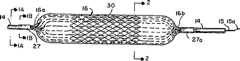
図1は、膨らまされたステントを有する、膨らまされたバルーンの側面立面図である。
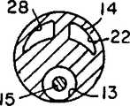
図1Aは、線1A−1Aにおける断面図であって、カテーテル・シャフトの複数のルーメンを示している。図1Bは、線1B−1Bにおける断面図であって、カテーテル・シャフトとバルーンとの間の取り付け部分を示している。
図2は、本発明によるバルーンの側面図であって、バルーンは、収縮され、包み込まれた状態にあり、畳まれたステントがバルーンの周りに設けられている。
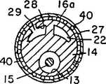
図2A及び2Bは、図1の線2−2における断面図である。図2A及び2Bでは、バルーンはふくらまされ、バルーンの周りに設けられたステントもふくらまされている。
図2C及び図2Dは、図2A及び図2Bと似ているが、図2C及び図2Dでは、膨張導管が膨らまされており、それによって、バルーン・カテーテルの周りに設けられたステントを充分に膨らます。膨らまされていない導管は薬品を投与するに用いられる。
好ましい実施例の説明
図を参照すると、バルーン式の医療用カテーテルが示されている。本発明におけるバルーン式カテーテルは、特に記述や説明がない限りは、冠状動脈症を治療するのに用いられる他のカテーテルと類似する。
従来と同様に、カテーテルでは、バルーン16をカテーテル・シャフト14に接続するのに、スリーブ27と27aを用いる。スリーブ27は、カテーテル・シャフト14を形成する複数のルーメン管のルーメンから医療バルーン16に、膨張用流体や薬品を送るために用いられる。
バルーン16はカテーテル・シャフト14の遠位端に設けられる。医療バルーン16は、ヒートシールまたは接着により、各端部16aと16bにおいて、カテーテル・シャフト14に取り付けられる。
図1A、1Bに示すように、カテーテル・シャフト14の内部に複数の膨張ルーメン22、28が設けられる。これらの膨張ルーメンのうちの1つは、バルーン16を膨らますのに用いられる。もう1つは、円状に配置された複数の膨張導管40から構成される個別のバルーンを膨らますのに用いられる。
図2Aに示すように、接続口20は、バルーン16の内部とルーメン22との間の連絡を可能にする。同様に、膨張ルーメン28については、接続口(図示せず)が膨張ルーメン28に設けられ、この接続口は、スリーブ27の内部に設けられ、膨張ルーメン28と、複数の導管40、25からなるアレイ(図2B、2Dに示す)との間の連絡を可能にする。膨張ルーメン28は、カテーテル・シャフト14の中を伸び、カテーテル・シャフト14の近位端に設けられた導入口(図示せず)と連絡する。
流体薬品は、カテーテル・シャフト14の近位端に設けられた導入口(図示せず)を通じて、カテーテル・シャフト14の内部に備えられたルーメン28を通じて導入することもできる。薬品送り導管25には、その壁に孔21を設けることができる。
従来の方法による体内通路へのカテーテルの挿入を助けるために、従来の調査チップを有する、従来のガイドワイヤ15を挿入できるように、第3のルーメン13は、カテーテル・シャフト14を完全に貫く。
好ましい実施例では、複数の導管25、40は、バルーン16の壁の境界に円状に配置される。複数の薬品送り導管25のそれぞれには、少なくとも一つの孔21が設けられ、これによって、カテーテルの導入された体内通路の中へ薬品を投与することができる。実施例によっては、これらの孔21は、バルーン16の境界の周りに螺旋状を配置することもできるし、薬品を導入し得るどのような構成をも用いることができる。
その他の実施例としては、薬品送り導管25の全長において、全く孔がなく、導管25の終端が、その遠端において薬品を投与するための開口部となっているものもある。薬品送り導管25の孔21は、バルーン16と薬品送り導管25の両方を拡張し、次のその壁をピンで軽く刺して、導管を収縮させて形成する。また、薬品送り導管25にレーザーを照射してルーメンを開けることもできる。孔21の直径は、投与される薬品の粘度、希望流速、および導管直径によって、0.0001〜2.5mmの範囲が望ましい。また、非常に粘度の高い物質や粒状の物質を投薬するのに、導管の外側に矩形の切れ込みを設けることもできる。薬品送り導管25の断面の形状は、投与しようとする薬品を受けることができるかどうかという点においてのみ重要である。正方形や長方形の導管は製作が容易で、必要な薬品投与機能が得られる。
バルーン16の壁には、円状に配置された膨張導管40からなるアレイも設けられる。ここに示した実施例では、各膨張導管40は2つの投薬導管25の間に設けられ、またその逆でもよい。ただし、ステント30を体内通路内に嵌め込むのに、充分なだけ膨張導管40がバルーンを膨らますことができるのであれば、このような位置関係を維持しなくても良い。各膨張導管40は、シャフト14に設けられる拡張ルーメン22と流体の流通する関係を有している。ルーメン20と接続口28を通じてバルーン16を膨らますと、バルーン16は開き、図1と2Aに示す概ね円筒形である構成が形成される。このように膨らますことにより、バルーン16の遠近両端は概ね円錐状の形状となる。後述するが、極めて壁厚の薄いバルーンを利用することが可能であるために、図2に示すような折り畳まれた状態では、バルーン16の輪郭はシャフト14の直径に近い。
図1、2A、および2Cはバルーン16が膨らまされた状態を示したものである。薬品送り導管25および膨張導管40は、共通側壁16dを共有する。各壁の壁厚は約0.0001から0.004インチの間で、0.003から0.002インチが望ましい。バルーン16の収縮輪郭は0.003インチ以下とすることができる。バルーンの内部、すなわちバルーンの内径は約0.02から2.0インチの間とすることができる。膨張導管40の幅は0.25から2.0mmまでとすることができる。図2Dに示すような膨張導管40は、幅が2倍、または3倍にもすることができ、したがって、後述のようにその周囲に設けられるステント30の直径を大幅に拡大することが可能である。概ね、バルーン壁内に6〜48本の導管が円状に配置される必要がある。
本発明のバルーン・カテーテルにおいて有用と実証されたステントは、第1と第2の端部を持ち、第1と第2の端部の間に設けられた壁面を持った管状の部材である。壁面は複数の交差する伸長性部材で形成され、その一部は管状部材の第1と第2の端部の中間において互いに交差する。管状部材には、部材の体内通路への送り込みを可能にする第1の直径を有する。また、管状部材には、管状部材の内部から半径方向に、外側に膨らます力が加わることにより形成される第2の拡張された直径を有する。第2の直径は可変で、移植をしようとする腔内の場所で部材を拡張させるために管状部材に加わる力に依存する。管状部材は、第1と第2の直径よりもさらに大きい第3の直径を有する。
第3の直径はステント30を実際に腔内に移植するのに使用する。ステント30は、ワイヤが互いに交差する場所で固定された複数のワイヤで形成されるのが望ましい。その一方、矩形メンバーは、やはり交差する場所で互いに固定された複数の細い棒材とすることができる。ステントには金属が最も頻繁に使用されるが、同様の形状に形成されたポリマー材料を使用することもできる。公知のとおり、ポリマー材料には狭窄治療後には体内に吸収され、消失させることができるという利点がある。
図2のとおり、バルーン16が包み込まれているときにはステント30はバルーンに密着する。(図1と2Aに示すように)バルーン16が膨張したときには、バルーンにかかる半径方向の外向きの力によってステント30が膨らます。ステント30を形成する個別の部材との間の間隔が広がる。ステント30は、膨らまされた状態でも、挿入された体内通路の中で動かすことができる。そのため、ステント30は正確な位置決めを行うために前後に動かすことができるという利点を持つ。正しい位置が得られたら、膨張導管40を膨らますことで、装置の直径がさらに拡大し、したがって、それを取り巻くステント30の直径も拡大される。次にステントは治療対象の体内通路に恒久的に移植される。
ステントを恒久的に着座させた後は、バルーンと膨張導管を収縮する。バルーン16をステントから抜き取り、カテーテルを体内通路から取り外す。本発明のバルーンでは、6mmのバルーン(拡張直径)を6.5〜7.0mmにまで膨らまし、ステントを膨らますことができる。さらに、薬品送り導管をバルーンの壁の内部に設けたことで、医師は、希望に応じて移植前に用いられる薬品とは異なる薬品を移植後に用いることができる。
本発明の基本的技術思想及び範囲内において、種々の変形及び変更をなし得ることは明らかである。本発明は、特許請求の範囲に基づいてのみ、解釈されなければならない。BACKGROUND OF THE INVENTION This invention relates to medical devices. The medical device utilizes a balloon catheter to place an inflatable intraluminal implant, commonly referred to as a stent, in a body passage such as an artery. Such stents can also be used for placement of interluminal implants such as aortic aneurysm implants.
The present invention particularly relates to medical devices including balloon catheters. This medical device can forcibly inflate a section of an artery narrowed by atherosclerotic lesions or stenosis by a balloon catheter, and at the same time, implant a stent at a predetermined place in the artery. You can also.
The invention further relates to a medical device comprising a balloon catheter and a method for operating the medical device. With this medical device and this method, a stent can be implanted into the body passage and a drug can be delivered to a predetermined location within the body passage.
Prior Art Devices including balloon catheters for inflating atherosclerotic lesions and stenosis are well known in the art. The device includes a balloon that can be inflated. A balloon is provided at the end of a catheter shaft having multiple lumens. The balloon is inflated by forcing the pressurized liquid into the balloon. By inflating the balloon, it captures the wall of the artery and widens the cross section. The use of balloons for implanting stents is also well known in the art. In the case of balloon implantation, a stent is placed on the balloon, the stent is positioned where treatment is to be performed, and the doctor observes the operation with an X-ray. When the correct location is reached, the balloon is deflated and removed, leaving only the stent in place. Next, a second balloon having a larger diameter is placed inside the stent, and the second balloon is expanded to a larger diameter with a pressurized solution, thereby further expanding the stent and treating the tube with the stent. Let the site be captured.
Such a procedure requires two balloons, so positioning the stent within the tube is difficult. In addition, it is difficult to accurately position the stent by moving it little by little. On the other hand, a large diameter balloon is used, and it is somewhat inflated for positioning, and then requires a large outline (diameter) balloon to be further inflated for implantation, and the physician can It is not possible to obtain a similar positive fit between the outside of the balloon and the stent so that proper positioning can be made.
Furthermore, it is well known to administer drugs from medical balloons. Medical balloons having a conduit in the wall and a hole or opening in the conduit have already been disclosed as prior art. US Patent No. 5,254,089 granted to Wang, and Wang's US Patent Application No. 08 / 088,327 filed July 7, 1993 (assigned to the same assignee as the present patent application) as a divisional application Discloses a balloon catheter. The balloon catheter has a plurality of conduits in the balloon wall that are perforated to administer medication.
The stent disclosed in US Pat. No. 4,733,665 to Palmaz can be placed around the balloon of the medical device of the present invention. A stent is a tubular device formed by a plurality of intersecting extensible members. The stent used here is a woven mesh, and this woven mesh is formed by winding at least two sets of spiral wires together to form a cylindrical body that can be expanded to a plurality of diameters. Two sets of helical wires are juxtaposed with one set relative to the other. The device has a first diameter for delivery into the body passage within the cavity. It also has a second expanded diameter to provide a radially outward (internal) expansion force, such as by a balloon. The second diameter of the stent is variable and depends on the force applied to expand it outward to expand the lumen of the body passage. The stent also has a third diameter for implantation, again due to internal forces within the passage.
In the prior art, balloons can be inflated above the diameter and stents can be inflated above the diameter, but usually two balloons were used to perform this procedure. One balloon is for feeding and the other larger balloon is for implantation. The reason is that the cross section of the balloon, which is large enough to perform the implantation, is larger than the cross section required for the procedure.
DISCLOSURE OF THE INVENTION In accordance with the present invention, an inflatable medical device has been found that provides a solution to the above problems. This medical device is a medical device for installing a stent by expanding a stent on one balloon in two stages. We have also developed a method of inflating a balloon and implanting a stent.
The medical device includes a catheter shaft and a balloon. The catheter shaft has at least two lumens through which fluid can pass. The balloon is hollow and can be inflated and has a generally cylindrical wall at the end of the catheter shaft.
The inside of the balloon is in a relationship in which fluid flows with one of the lumens, and the inflation fluid is supplied to the inside of the balloon. A circular array of inflation conduits is provided inside the balloon wall. These expansion conduits are individually divided and spaced from each other. These interiors are in a relationship of fluid flow with another lumen in the shaft to obtain the inflation fluid, but there is usually no fluid flow relationship between them.
A stent is provided around the exterior of the balloon wall. The stent is radially outwardly expanded from a narrow insertion diameter to a larger second diameter by inflating the balloon and then to a larger third diameter by inflating the inflation conduit. Can inflate. This allows the stent to expand in the body passageway and implant the stent.
In an embodiment of the present invention, one of the catheter shaft lumens having two inflation lumens is used to administer the drug from a conduit in the balloon wall. In order to administer the drug and inflate the inflation conduit, the inflation conduit is in a fluid relationship with the inflation lumen. Therefore, the device of the present invention can not only insert and implant a stent, but also accurately deliver a drug to a treatment site in a body passage.
The catheter of the present invention is made by extruding two different polymeric materials simultaneously. One of the extruded materials forms a tube. The other extruded material (provided as individual segments within the wall of the tube) forms an array of circularly arranged strands. Useful polymers are polyethylene terephthalate as the tube and polyethylene as the strand. The strand is withdrawn from the tube to form a conduit. The tube is then expanded and the conduit is expanded. A portion of the conduit, if not necessarily all, can be drilled into a dosing conduit, and the remaining unperforated conduit can be an expansion conduit. The balloon and conduit are attached to the catheter in the usual manner and the lumen is in fluid communication with the inflatable portion of the balloon. The balloon is then wrapped in the usual manner, and a stent with the smallest diameter is placed around the wrapped balloon.
After insertion in approximately the correct position, the catheter shaft balloon is inflated to the first diameter by inflating the stent to the first diameter by one of a plurality of inflation lumens, positioning the stent, and body passage Allows forcible expansion of the cross-section. Next, an inflation fluid is pumped through another one of the plurality of inflation lumens to inflate the inflation conduit and inflate the balloon to a larger diameter, thereby inflating the stent to a larger diameter and into the stent body passageway. It is possible to fit and transplant.
In yet another embodiment, the drug can be administered through a hole in some of the plurality of conduits provided in the balloon wall. In either embodiment, after implanting the stent and introducing the drug, the balloon is withdrawn from the stent that is currently fitted into the body passageway.
[Brief description of the drawings]
FIG. 1 is a side elevational view of an inflated balloon having an inflated stent.
FIG. 1A is a cross-sectional view taken along line 1A-1A, showing a plurality of lumens of the catheter shaft. FIG. 1B is a cross-sectional view taken along line 1B-1B, showing the attachment between the catheter shaft and the balloon.
FIG. 2 is a side view of a balloon according to the present invention in which the balloon is in a deflated and encased state and a folded stent is provided around the balloon.
2A and 2B are cross-sectional views taken along line 2-2 of FIG. In FIGS. 2A and 2B, the balloon is inflated, and the stent provided around the balloon is also inflated.
2C and 2D are similar to FIGS. 2A and 2B, but in FIGS. 2C and 2D, the inflation conduit is inflated, thereby sufficiently inflating the stent provided around the balloon catheter . An uninflated conduit is used to administer the drug.
Referring to the illustration of the preferred embodiment, a balloon-type medical catheter is shown. The balloon catheter of the present invention is similar to other catheters used to treat coronary artery disease unless otherwise stated or explained.
As in the prior art, the catheter uses
As shown in FIGS. 1A and 1B, a plurality of
As shown in FIG. 2A, the
Fluid chemicals can also be introduced through a
The
In the preferred embodiment, the plurality of
In another embodiment, there is no hole in the entire length of the
The wall of the
1, 2A and 2C show the
A stent that has proven useful in the balloon catheter of the present invention is a tubular member having first and second ends and a wall surface provided between the first and second ends. The wall surface is formed of a plurality of intersecting extensible members, some of which intersect each other in the middle of the first and second ends of the tubular member. The tubular member has a first diameter that allows delivery of the member into the body passage. Further, the tubular member has a second expanded diameter formed by applying a force that expands outward in the radial direction from the inside of the tubular member. The second diameter is variable and depends on the force applied to the tubular member to expand the member at a location within the cavity to be implanted. The tubular member has a third diameter that is greater than the first and second diameters.
The third diameter is used to actually implant the
As shown in FIG. 2, when the
After the stent is permanently seated, the balloon and inflation conduit are deflated. The
Obviously, various modifications and changes may be made within the basic technical idea and scope of the invention. The invention should only be construed on the basis of the claims.
Claims (11)
Translated fromJapaneseカテーテル・シャフトと、バルーンと、複数の膨張導管と、ステントとを含んでおり、
前記カテーテル・シャフトは、その内部に少なくとも2つのルーメンが設けられ、前記体内通路の内部に配置されるのに適した遠位端を有し、
前記バルーンは、中空であり、膨らますことができ、ほぼ円筒形である壁によって画定され、近位端を有し、前記近位端は前記カテーテル・シャフトの遠位端に設けられており、前記バルーンの内部は前記複数のルーメンの1つと流体の流通する関係にあり、それによって、前記バルーンの内部に膨張用流体を供給し、
前記複数の膨張導管は、前記壁の内部に円状に配置され、前記壁の内部で互いに間隔を隔てて設けられ、それによって、環状のアレイを形成し、
前記複数の膨張導管の内部は、もう一方の前記ルーメンと流体の流通する関係にあり、それによって、前記複数の膨張導管に膨張用流体を供給し、
前記ステントは、
前記バルーンの壁の外側の周りに、取り外しできるように設けられ、
前記バルーンを膨らますことによって、細い挿入用直径から、より大きい第2の直径にまで、径方向に外向きに膨らますことができ、その次に、前記複数の膨張導管を膨らますことによって、さらに大きい第3の直径にまで、膨らますことができ、それによって、前記体内通路を拡大し、前記ステントを嵌め込む
医療装置。An inflatable medical device that installs the stent in a body passage by inflating the stent in two stages,
A catheter shaft, a balloon, a plurality of inflation conduits, and a stent;
The catheter shaft has at least two lumens therein and has a distal end suitable for placement within the body passage;
The balloon is hollow, inflatable, defined by a generally cylindrical wall, having a proximal end, the proximal end being provided at a distal end of the catheter shaft; The interior of the balloon is in fluid communication with one of the plurality of lumens, thereby supplying inflation fluid to the interior of the balloon;
The plurality of expansion conduits are arranged circularly within the wall and are spaced apart from each other within the wall, thereby forming an annular array;
The interior of the plurality of inflation conduits is in fluid communication with the other lumen, thereby supplying inflation fluid to the plurality of inflation conduits;
The stent is
Around the outside of the wall of the balloon is provided so as to be removable,
By inflating the balloon, it can be inflated radially outward from a narrow insertion diameter to a larger second diameter, and then by inflating the plurality of inflation conduits, 3. A medical device that can be inflated to a diameter of 3, thereby expanding the body passageway and fitting the stent.
前記複数の膨張導管は、前記バルーンの周り、一様にアレイ状に、かつ、互いに間隔を隔てて設けられる
医療装置。A medical device according to claim 1,
The plurality of inflation conduits are provided in a uniform array around the balloon and spaced apart from each other.
前記ステントは、織り込み網状体であり、前記織り込み網状体は、螺旋状に設けられた少なくとも2組のワイヤからなり、前記2組のワイヤは、相関的に並置され、かつ、一緒に巻き付られ、複数の直径に膨張可能な筒状体を形成する
医療装置。A medical device according to claim 1,
The stent is a woven mesh, and the woven mesh is composed of at least two sets of wires provided in a spiral shape, and the two sets of wires are arranged in parallel with each other and wound together. A medical device that forms a cylindrical body that can expand to a plurality of diameters.
カテーテル・シャフトと、バルーンと、複数の薬品送り導管と、複数の膨張導管と、ステントと、第1の手段と、第2の手段とを含んでおり、
前記カテーテル・シャフトは、その内部に、複数のルーメンが設けられ、血管通路内に配置するのに適した遠位端を有し、
前記バルーンは、膨らますことができ、概ね円筒形である壁によって画定され、膨張用流体を受けるのに適し、前記カテーテル・シャフトの遠位端に設けられており、
前記複数の薬品送り導管は、前記バルーンの壁の内部に円状に設けられ、アレイを形成し、
前記薬品送り導管は、前記複数のルーメンのうちの1つから、前記血管通路の中の予め定められた位置に、薬品を送るのに適しており、
前記複数の膨張導管は、前記壁の内部に円状に設けられ、前記壁の内部で互いに間隔を隔てて設けられ、それによって、環状のアレイを形成し、
前記第1の手段は前記シャフトの内部に位置する前記複数のルーメンのうちの1つから前記バルーンに膨張用流体を送るための手段であり、前記第2の手段は前記複数のルーメンのうちの別なもう1つから前記薬品送り導管に薬品を含む膨張用流体を送るための手段であり、前記第1の手段および前記第2の手段によって、前記バルーンの直径を、前記バルーンと、前記膨張導管とにより2段階で拡大することができ、
前記ステントは、
前記バルーンの壁の外側の周りに、取り外しできるように設けられ、
前記バルーンを膨らますことによって、細い挿入の直径から、より大きい第2の直径にまで、径方向に外向きに膨らますことができ、その次に、前記複数の膨張導管を膨らますことによって、さらに大きい第3の直径まで、膨らますことができ、それによって、前記体内通路を拡大し、前記ステントを嵌め込む
医療装置。An inflatable medical device for placing the stent in a vascular passage by inflating the stent in two stages and delivering the drug into the blood vessel;
A catheter shaft, a balloon, a plurality of drug delivery conduits, a plurality of inflation conduits, a stent, a first means, and a second means;
The catheter shaft has a distal end within which a plurality of lumens are provided and suitable for placement within a vascular passageway;
The balloon can be inflated, is defined by a generally cylindrical wall, is suitable for receiving inflation fluid, and is provided at the distal end of the catheter shaft;
The plurality of drug delivery conduits are circularly provided inside the balloon wall to form an array;
The drug delivery conduit is suitable for delivering a drug from one of the plurality of lumens to a predetermined location in the vascular passageway;
The plurality of expansion conduits are circularly provided inside the wall and spaced apart from each other within the wall, thereby forming an annular array;
The first means is means for sending inflation fluid from one of the plurality of lumens located within the shaft to the balloon, and the second means is one of the plurality of lumens. Means for delivering an inflation fluid containing a medicament from another to the medicament delivery conduit, wherein the first means and the second means reduce the diameter of the balloon to the balloon and the inflation Can be expanded in two stages with a conduit,
The stent is
Around the outside of the wall of the balloon is provided so as to be removable,
By inflating the balloon, it is possible to inflate radially outward from a narrow insertion diameter to a larger second diameter, and then by inflating the plurality of inflation conduits A medical device that can be inflated to a diameter of 3, thereby expanding the body passageway and fitting the stent.
前記複数の薬品送り導管は、前記バルーンの周りに設けられ、前記バルーン上で互いに間隔を保ち、互いに個別に分割される
医療装置。A medical device according to claim 4,
The plurality of drug delivery conduits are provided around the balloon, are spaced apart from each other on the balloon, and are individually divided from each other.
前記第2の手段は、前記薬品送り導管上に設けられた孔を含む
医療装置。A medical device according to claim 4,
Said second means is a medical device comprising a hole provided on said drug delivery conduit.
前記薬品送り導管は、全長にわたって孔を有さず、その遠位端に設けられた開口部で終端することにより前記バルーンからの薬品の送出を可能とする
医療装置。A medical device according to claim 4,
The medicine feeding conduit does not have a hole over its entire length, and terminates at an opening provided at a distal end thereof, thereby enabling delivery of medicine from the balloon.
第1のステップは、2つの異種ポリマー材料を同時に押し出すステップであり、第1のポリマー材料が管をなし、もう1つのポリマー材料が前記管の中に分割された個別のストランドのアレイとなり、前記ストランドは前記管内に個別に囲まれ、
第2のステップは、前記管から前記ストランドを抜き取り、前記チューブ内に導管を形成し、その後、前記チューブの一部を拡大させてバルーンを形成し、少なくとも一部の導管を拡大させて膨張導管を形成するステップであり、
第3のステップは、前記バルーンの壁の外部の周囲に、ステントを取り外し可能な状態で設けるステップであり、前記ステントは、前記バルーンを膨らますことによって、細い挿入直径からより大きな第2の直径にまで径方向に外向きに膨らますことができ、さらに前記膨張導管を膨らますことで、より大きな第3の直径にまで膨らますことができる
バルーンの製作方法。A method of making a medication and stent delivery balloon for a catheter comprising a plurality of steps,
The first step is the step of extruding two dissimilar polymer materials simultaneously, the first polymer material forming a tube and the other polymer material being an array of individual strands divided into the tube, The strands are individually enclosed within the tube,
The second step extracts the strand from the tube, forms a conduit in the tube, and then expands a portion of the tube to form a balloon, and expands at least a portion of the conduit to expand the inflation conduit. Is the step of forming
The third step is the step of removably providing a stent around the exterior of the balloon wall, wherein the stent is expanded from a narrow insertion diameter to a larger second diameter by inflating the balloon. A method of manufacturing a balloon that can be inflated radially outward and further inflated to the larger third diameter.
薬品送り導管を形成するために、一部の前記導管を穿孔するステップを含む
バルーンの製作方法。A method as claimed in claim 8, comprising:
A method of making a balloon comprising drilling a portion of said conduit to form a drug delivery conduit.
ポリマーは、管用がポリエチレン・テレフタレートで、ストランド用がポリエチレンである
バルーンの製作方法。10. A method as claimed in claim 9, comprising:
The polymer is a balloon manufacturing method in which polyethylene terephthalate is used for pipes and polyethylene is used for strands.
押し出された管の壁の厚さが0.05〜3.75mmで、ストランドの直径が約0.0125〜2.5mmである
バルーンの製作方法。10. A method as claimed in claim 9, comprising:
A method of making a balloon wherein the extruded tube wall has a thickness of 0.05 to 3.75 mm and a strand diameter of about 0.0125 to 2.5 mm.
Applications Claiming Priority (3)
| Application Number | Priority Date | Filing Date | Title |
|---|---|---|---|
| US08/361,963 | 1994-12-22 | ||
| US08/361,963US5755722A (en) | 1994-12-22 | 1994-12-22 | Stent placement device with medication dispenser and method |
| PCT/US1995/016643WO1996019257A1 (en) | 1994-12-22 | 1995-12-21 | Stent placement device with medication dispenser and method |
Publications (2)
| Publication Number | Publication Date |
|---|---|
| JPH11506350A JPH11506350A (en) | 1999-06-08 |
| JP3756185B2true JP3756185B2 (en) | 2006-03-15 |
Family
ID=23424125
Family Applications (1)
| Application Number | Title | Priority Date | Filing Date |
|---|---|---|---|
| JP51998796AExpired - Fee RelatedJP3756185B2 (en) | 1994-12-22 | 1995-12-21 | Stent placement device with dosing device and method thereof |
Country Status (6)
| Country | Link |
|---|---|
| US (2) | US5755722A (en) |
| EP (1) | EP0799073B1 (en) |
| JP (1) | JP3756185B2 (en) |
| CA (1) | CA2206536C (en) |
| DE (1) | DE69532208T2 (en) |
| WO (1) | WO1996019257A1 (en) |
Families Citing this family (99)
| Publication number | Priority date | Publication date | Assignee | Title |
|---|---|---|---|---|
| US5792105A (en)* | 1996-09-11 | 1998-08-11 | Boston Scientific Corporation | Multichannel balloon catheter for delivering fluid |
| US5976181A (en)* | 1997-09-22 | 1999-11-02 | Ave Connaught | Balloon mounted stent and method therefor |
| JP2003522550A (en)* | 1998-02-10 | 2003-07-29 | アーテミス・メディカル・インコーポレイテッド | Occlusion, fixation, tensioning, and diverting devices and methods of use |
| US7713297B2 (en) | 1998-04-11 | 2010-05-11 | Boston Scientific Scimed, Inc. | Drug-releasing stent with ceramic-containing layer |
| US6336937B1 (en) | 1998-12-09 | 2002-01-08 | Gore Enterprise Holdings, Inc. | Multi-stage expandable stent-graft |
| US6471968B1 (en) | 2000-05-12 | 2002-10-29 | Regents Of The University Of Michigan | Multifunctional nanodevice platform |
| US6743219B1 (en) | 2000-08-02 | 2004-06-01 | Cordis Corporation | Delivery apparatus for a self-expanding stent |
| US20020016597A1 (en)* | 2000-08-02 | 2002-02-07 | Dwyer Clifford J. | Delivery apparatus for a self-expanding stent |
| US20070031607A1 (en)* | 2000-12-19 | 2007-02-08 | Alexander Dubson | Method and apparatus for coating medical implants |
| US20040030377A1 (en)* | 2001-10-19 | 2004-02-12 | Alexander Dubson | Medicated polymer-coated stent assembly |
| US7244272B2 (en) | 2000-12-19 | 2007-07-17 | Nicast Ltd. | Vascular prosthesis and method for production thereof |
| US20020084178A1 (en) | 2000-12-19 | 2002-07-04 | Nicast Corporation Ltd. | Method and apparatus for manufacturing polymer fiber shells via electrospinning |
| US6752829B2 (en)* | 2001-01-30 | 2004-06-22 | Scimed Life Systems, Inc. | Stent with channel(s) for containing and delivering a biologically active material and method for manufacturing the same |
| JP4130364B2 (en)* | 2001-03-20 | 2008-08-06 | ナイキャスト リミテッド | Portable electrospinning device |
| WO2003002243A2 (en) | 2001-06-27 | 2003-01-09 | Remon Medical Technologies Ltd. | Method and device for electrochemical formation of therapeutic species in vivo |
| US7041139B2 (en) | 2001-12-11 | 2006-05-09 | Boston Scientific Scimed, Inc. | Ureteral stents and related methods |
| US7169170B2 (en) | 2002-02-22 | 2007-01-30 | Cordis Corporation | Self-expanding stent delivery system |
| US20040155053A1 (en)* | 2003-02-10 | 2004-08-12 | Sanchez Khiro M. | Stent package |
| US20080200975A1 (en)* | 2004-01-06 | 2008-08-21 | Nicast Ltd. | Vascular Prosthesis with Anastomotic Member |
| JP2008510829A (en)* | 2004-08-25 | 2008-04-10 | ザ リージェンツ オブ ザ ユニバーシティ オブ ミシガン | Compositions based on dendrimers and their use |
| JP4713589B2 (en) | 2004-09-01 | 2011-06-29 | クック インコーポレイテッド | Delivery system for hydration of intraluminal medical devices |
| US20060085058A1 (en)* | 2004-10-20 | 2006-04-20 | Rosenthal Arthur L | System and method for delivering a biologically active material to a body lumen |
| US20100331947A1 (en)* | 2005-02-17 | 2010-12-30 | Alon Shalev | Inflatable Medical Device |
| US7396366B2 (en)* | 2005-05-11 | 2008-07-08 | Boston Scientific Scimed, Inc. | Ureteral stent with conforming retention structure |
| WO2007008829A2 (en) | 2005-07-08 | 2007-01-18 | C.R. Bard, Inc. | Drug delivery system |
| US20070041934A1 (en)* | 2005-08-12 | 2007-02-22 | Regents Of The University Of Michigan | Dendrimer based compositions and methods of using the same |
| US8840660B2 (en) | 2006-01-05 | 2014-09-23 | Boston Scientific Scimed, Inc. | Bioerodible endoprostheses and methods of making the same |
| US8089029B2 (en) | 2006-02-01 | 2012-01-03 | Boston Scientific Scimed, Inc. | Bioabsorbable metal medical device and method of manufacture |
| US20070224235A1 (en) | 2006-03-24 | 2007-09-27 | Barron Tenney | Medical devices having nanoporous coatings for controlled therapeutic agent delivery |
| US8187620B2 (en) | 2006-03-27 | 2012-05-29 | Boston Scientific Scimed, Inc. | Medical devices comprising a porous metal oxide or metal material and a polymer coating for delivering therapeutic agents |
| US8048150B2 (en) | 2006-04-12 | 2011-11-01 | Boston Scientific Scimed, Inc. | Endoprosthesis having a fiber meshwork disposed thereon |
| US8815275B2 (en) | 2006-06-28 | 2014-08-26 | Boston Scientific Scimed, Inc. | Coatings for medical devices comprising a therapeutic agent and a metallic material |
| WO2008002778A2 (en) | 2006-06-29 | 2008-01-03 | Boston Scientific Limited | Medical devices with selective coating |
| EP2054537A2 (en) | 2006-08-02 | 2009-05-06 | Boston Scientific Scimed, Inc. | Endoprosthesis with three-dimensional disintegration control |
| EP2068757B1 (en) | 2006-09-14 | 2011-05-11 | Boston Scientific Limited | Medical devices with drug-eluting coating |
| ES2357661T3 (en) | 2006-09-15 | 2011-04-28 | Boston Scientific Scimed, Inc. | BIOEROSIONABLE ENDOPROOTHESIS WITH BIOESTABLE INORGANIC LAYERS. |
| JP2010503489A (en) | 2006-09-15 | 2010-02-04 | ボストン サイエンティフィック リミテッド | Biodegradable endoprosthesis and method for producing the same |
| EP2959925B1 (en) | 2006-09-15 | 2018-08-29 | Boston Scientific Limited | Medical devices and methods of making the same |
| WO2008034066A1 (en) | 2006-09-15 | 2008-03-20 | Boston Scientific Limited | Bioerodible endoprostheses and methods of making the same |
| WO2008036548A2 (en) | 2006-09-18 | 2008-03-27 | Boston Scientific Limited | Endoprostheses |
| US7981150B2 (en) | 2006-11-09 | 2011-07-19 | Boston Scientific Scimed, Inc. | Endoprosthesis with coatings |
| ES2506144T3 (en) | 2006-12-28 | 2014-10-13 | Boston Scientific Limited | Bioerodible endoprosthesis and their manufacturing procedure |
| US8070797B2 (en) | 2007-03-01 | 2011-12-06 | Boston Scientific Scimed, Inc. | Medical device with a porous surface for delivery of a therapeutic agent |
| US8431149B2 (en) | 2007-03-01 | 2013-04-30 | Boston Scientific Scimed, Inc. | Coated medical devices for abluminal drug delivery |
| US8067054B2 (en) | 2007-04-05 | 2011-11-29 | Boston Scientific Scimed, Inc. | Stents with ceramic drug reservoir layer and methods of making and using the same |
| AU2008275501A1 (en)* | 2007-04-19 | 2009-01-15 | The Regents Of The University Of Michigan | Dendrimer based compositions and methods of using the same |
| US7976915B2 (en) | 2007-05-23 | 2011-07-12 | Boston Scientific Scimed, Inc. | Endoprosthesis with select ceramic morphology |
| US8002823B2 (en) | 2007-07-11 | 2011-08-23 | Boston Scientific Scimed, Inc. | Endoprosthesis coating |
| US7942926B2 (en) | 2007-07-11 | 2011-05-17 | Boston Scientific Scimed, Inc. | Endoprosthesis coating |
| EP2187988B1 (en) | 2007-07-19 | 2013-08-21 | Boston Scientific Limited | Endoprosthesis having a non-fouling surface |
| US8815273B2 (en) | 2007-07-27 | 2014-08-26 | Boston Scientific Scimed, Inc. | Drug eluting medical devices having porous layers |
| US7931683B2 (en) | 2007-07-27 | 2011-04-26 | Boston Scientific Scimed, Inc. | Articles having ceramic coated surfaces |
| WO2009018340A2 (en) | 2007-07-31 | 2009-02-05 | Boston Scientific Scimed, Inc. | Medical device coating by laser cladding |
| JP2010535541A (en) | 2007-08-03 | 2010-11-25 | ボストン サイエンティフィック リミテッド | Coating for medical devices with large surface area |
| US8052745B2 (en) | 2007-09-13 | 2011-11-08 | Boston Scientific Scimed, Inc. | Endoprosthesis |
| US8579956B2 (en)* | 2007-09-28 | 2013-11-12 | Abbott Cardiovascular Systems Inc. | Methods and devices for treating lesions |
| US8518099B2 (en)* | 2007-10-10 | 2013-08-27 | C. R. Bard, Inc. | Low friction vascular implant delivery device |
| US7938855B2 (en) | 2007-11-02 | 2011-05-10 | Boston Scientific Scimed, Inc. | Deformable underlayer for stent |
| US8216632B2 (en) | 2007-11-02 | 2012-07-10 | Boston Scientific Scimed, Inc. | Endoprosthesis coating |
| US8029554B2 (en) | 2007-11-02 | 2011-10-04 | Boston Scientific Scimed, Inc. | Stent with embedded material |
| US8457757B2 (en) | 2007-11-26 | 2013-06-04 | Micro Transponder, Inc. | Implantable transponder systems and methods |
| US9089707B2 (en) | 2008-07-02 | 2015-07-28 | The Board Of Regents, The University Of Texas System | Systems, methods and devices for paired plasticity |
| US9375327B2 (en) | 2007-12-12 | 2016-06-28 | Intact Vascular, Inc. | Endovascular implant |
| US9603730B2 (en) | 2007-12-12 | 2017-03-28 | Intact Vascular, Inc. | Endoluminal device and method |
| US8128677B2 (en) | 2007-12-12 | 2012-03-06 | Intact Vascular LLC | Device and method for tacking plaque to a blood vessel wall |
| US10166127B2 (en) | 2007-12-12 | 2019-01-01 | Intact Vascular, Inc. | Endoluminal device and method |
| US7896911B2 (en) | 2007-12-12 | 2011-03-01 | Innovasc Llc | Device and method for tacking plaque to blood vessel wall |
| US10022250B2 (en) | 2007-12-12 | 2018-07-17 | Intact Vascular, Inc. | Deployment device for placement of multiple intraluminal surgical staples |
| WO2009151687A2 (en) | 2008-03-12 | 2009-12-17 | The Regents Of The University Of Michigan | Dendrimer conjugates |
| US8920491B2 (en) | 2008-04-22 | 2014-12-30 | Boston Scientific Scimed, Inc. | Medical devices having a coating of inorganic material |
| US8932346B2 (en) | 2008-04-24 | 2015-01-13 | Boston Scientific Scimed, Inc. | Medical devices having inorganic particle layers |
| US7998192B2 (en) | 2008-05-09 | 2011-08-16 | Boston Scientific Scimed, Inc. | Endoprostheses |
| US8236046B2 (en) | 2008-06-10 | 2012-08-07 | Boston Scientific Scimed, Inc. | Bioerodible endoprosthesis |
| EP2303350A2 (en) | 2008-06-18 | 2011-04-06 | Boston Scientific Scimed, Inc. | Endoprosthesis coating |
| US7985252B2 (en) | 2008-07-30 | 2011-07-26 | Boston Scientific Scimed, Inc. | Bioerodible endoprosthesis |
| WO2010039861A2 (en) | 2008-09-30 | 2010-04-08 | The Regents Of The University Of Michigan | Dendrimer conjugates |
| US8382824B2 (en) | 2008-10-03 | 2013-02-26 | Boston Scientific Scimed, Inc. | Medical implant having NANO-crystal grains with barrier layers of metal nitrides or fluorides |
| US9017644B2 (en) | 2008-11-07 | 2015-04-28 | The Regents Of The University Of Michigan | Methods of treating autoimmune disorders and/or inflammatory disorders |
| US8231980B2 (en) | 2008-12-03 | 2012-07-31 | Boston Scientific Scimed, Inc. | Medical implants including iridium oxide |
| EP2403546A2 (en) | 2009-03-02 | 2012-01-11 | Boston Scientific Scimed, Inc. | Self-buffering medical implants |
| US8071156B2 (en) | 2009-03-04 | 2011-12-06 | Boston Scientific Scimed, Inc. | Endoprostheses |
| US8287937B2 (en) | 2009-04-24 | 2012-10-16 | Boston Scientific Scimed, Inc. | Endoprosthese |
| EP2488172A4 (en) | 2009-10-13 | 2014-08-13 | Univ Michigan | DENDRIMER COMPOSITIONS AND METHODS OF SYNTHESIS |
| US8912323B2 (en) | 2009-10-30 | 2014-12-16 | The Regents Of The University Of Michigan | Multifunctional small molecules |
| US8668732B2 (en) | 2010-03-23 | 2014-03-11 | Boston Scientific Scimed, Inc. | Surface treated bioerodible metal endoprostheses |
| US10285831B2 (en) | 2011-06-03 | 2019-05-14 | Intact Vascular, Inc. | Endovascular implant |
| WO2013085718A1 (en) | 2011-12-08 | 2013-06-13 | The Regents Of The University Of Michigan | Multifunctional small molecules |
| CN110464520A (en) | 2012-01-25 | 2019-11-19 | 因特脉管有限公司 | Intracavitary unit and method |
| US10286190B2 (en) | 2013-12-11 | 2019-05-14 | Cook Medical Technologies Llc | Balloon catheter with dynamic vessel engaging member |
| WO2015104589A1 (en) | 2014-01-13 | 2015-07-16 | Shanghai Lawring Biomedical Co., Ltd | Dendrimer compositions, methods of synthesis, and uses thereof |
| EP2898920B1 (en) | 2014-01-24 | 2018-06-06 | Cook Medical Technologies LLC | Articulating balloon catheter |
| US9433520B2 (en) | 2015-01-29 | 2016-09-06 | Intact Vascular, Inc. | Delivery device and method of delivery |
| US9375336B1 (en) | 2015-01-29 | 2016-06-28 | Intact Vascular, Inc. | Delivery device and method of delivery |
| CA2979712C (en) | 2015-03-25 | 2024-01-23 | The Regents Of The University Of Michigan | Nanoparticle compositions for delivery of biomacromolecules |
| US10993824B2 (en) | 2016-01-01 | 2021-05-04 | Intact Vascular, Inc. | Delivery device and method of delivery |
| CA3017813C (en) | 2016-03-17 | 2021-12-07 | Oslo Universitetssykehus Hf | Fusion proteins targeting tumour associated macrophages for treating cancer |
| US20190358263A1 (en) | 2016-12-07 | 2019-11-28 | Oslo Universitetssykehus Hf | Compositions and Methods for Cell Therapy |
| US11660218B2 (en) | 2017-07-26 | 2023-05-30 | Intact Vascular, Inc. | Delivery device and method of delivery |
| WO2019195641A2 (en) | 2018-04-06 | 2019-10-10 | The Regents Of The University Of Michigan | Inhibitors of rho/mrtf/srf-mediated gene transcription and methods for use of the same |
Family Cites Families (7)
| Publication number | Priority date | Publication date | Assignee | Title |
|---|---|---|---|---|
| US4733665C2 (en)* | 1985-11-07 | 2002-01-29 | Expandable Grafts Partnership | Expandable intraluminal graft and method and apparatus for implanting an expandable intraluminal graft |
| US4762130A (en)* | 1987-01-15 | 1988-08-09 | Thomas J. Fogarty | Catheter with corkscrew-like balloon |
| US5213576A (en)* | 1991-06-11 | 1993-05-25 | Cordis Corporation | Therapeutic porous balloon catheter |
| US5254089A (en)* | 1992-04-02 | 1993-10-19 | Boston Scientific Corp. | Medication dispensing balloon catheter |
| US5403280A (en)* | 1993-02-16 | 1995-04-04 | Wang; James C. | Inflatable perfusion catheter |
| US5512051A (en)* | 1993-02-16 | 1996-04-30 | Boston Scientific Corporation | Slip-layered catheter balloon |
| DE4324218A1 (en)* | 1993-07-19 | 1995-01-26 | Bavaria Med Tech | Cuff catheter |
- 1994
- 1994-12-22USUS08/361,963patent/US5755722A/ennot_activeExpired - Lifetime
- 1995
- 1995-12-21WOPCT/US1995/016643patent/WO1996019257A1/enactiveIP Right Grant
- 1995-12-21JPJP51998796Apatent/JP3756185B2/ennot_activeExpired - Fee Related
- 1995-12-21EPEP95944171Apatent/EP0799073B1/ennot_activeExpired - Lifetime
- 1995-12-21DEDE69532208Tpatent/DE69532208T2/ennot_activeExpired - Lifetime
- 1995-12-21CACA002206536Apatent/CA2206536C/ennot_activeExpired - Fee Related
- 1997
- 1997-12-29USUS08/999,175patent/US5928247A/ennot_activeExpired - Lifetime
Also Published As
| Publication number | Publication date |
|---|---|
| EP0799073A4 (en) | 1999-02-17 |
| CA2206536A1 (en) | 1996-06-27 |
| EP0799073A1 (en) | 1997-10-08 |
| EP0799073B1 (en) | 2003-11-26 |
| WO1996019257A1 (en) | 1996-06-27 |
| CA2206536C (en) | 2007-05-29 |
| DE69532208T2 (en) | 2004-08-26 |
| DE69532208D1 (en) | 2004-01-08 |
| JPH11506350A (en) | 1999-06-08 |
| US5755722A (en) | 1998-05-26 |
| US5928247A (en) | 1999-07-27 |
Similar Documents
| Publication | Publication Date | Title |
|---|---|---|
| JP3756185B2 (en) | Stent placement device with dosing device and method thereof | |
| JP3339003B2 (en) | Inflatable medical device for delivering a drug and method of making the same | |
| US4787388A (en) | Method for opening constricted regions in the cardiovascular system | |
| US7955371B2 (en) | System and method for stent deployment and infusion of a therapeutic agent into tissue adjacent to the stent ends | |
| CN108992204B (en) | Balloon catheter with multiple inflation lumens and related methods | |
| JP3787358B2 (en) | Multi-hole drug delivery balloon | |
| US7238168B2 (en) | Exchangeable catheter | |
| US7131986B2 (en) | Catheter having exchangeable balloon | |
| US9174030B2 (en) | Weeping balloon catheter | |
| EP0567788A1 (en) | Method and apparatus for intravascular drug delivery | |
| US20170361073A1 (en) | Balloon catheter with centralized vent hole | |
| US20040133270A1 (en) | Drug eluting stent and methods of manufacture | |
| JPH08506752A (en) | Inflatable perfusion catheter | |
| US6117386A (en) | Centering perfusion delivery catheter and method of manufacture | |
| US20060074396A1 (en) | Stent delivery system | |
| CN116420081A (en) | Device and method for repairing tissue |
Legal Events
| Date | Code | Title | Description |
|---|---|---|---|
| A977 | Report on retrieval | Free format text:JAPANESE INTERMEDIATE CODE: A971007 Effective date:20050317 | |
| A131 | Notification of reasons for refusal | Free format text:JAPANESE INTERMEDIATE CODE: A131 Effective date:20050419 | |
| A601 | Written request for extension of time | Free format text:JAPANESE INTERMEDIATE CODE: A601 Effective date:20050719 | |
| A602 | Written permission of extension of time | Free format text:JAPANESE INTERMEDIATE CODE: A602 Effective date:20050905 | |
| A521 | Request for written amendment filed | Free format text:JAPANESE INTERMEDIATE CODE: A523 Effective date:20051011 | |
| TRDD | Decision of grant or rejection written | ||
| A01 | Written decision to grant a patent or to grant a registration (utility model) | Free format text:JAPANESE INTERMEDIATE CODE: A01 Effective date:20051206 | |
| A61 | First payment of annual fees (during grant procedure) | Free format text:JAPANESE INTERMEDIATE CODE: A61 Effective date:20051221 | |
| R150 | Certificate of patent or registration of utility model | Free format text:JAPANESE INTERMEDIATE CODE: R150 | |
| LAPS | Cancellation because of no payment of annual fees |