JP3752126B2 - AF ranging optical system - Google Patents
AF ranging optical systemDownload PDFInfo
- Publication number
- JP3752126B2 JP3752126B2JP2000066230AJP2000066230AJP3752126B2JP 3752126 B2JP3752126 B2JP 3752126B2JP 2000066230 AJP2000066230 AJP 2000066230AJP 2000066230 AJP2000066230 AJP 2000066230AJP 3752126 B2JP3752126 B2JP 3752126B2
- Authority
- JP
- Japan
- Prior art keywords
- light
- focus
- optical system
- objective lens
- distance measuring
- Prior art date
- Legal status (The legal status is an assumption and is not a legal conclusion. Google has not performed a legal analysis and makes no representation as to the accuracy of the status listed.)
- Expired - Fee Related
Links
- 230000003287optical effectEffects0.000titleclaimsdescription64
- 238000001514detection methodMethods0.000claimsdescription40
- 210000001747pupilAnatomy0.000claimsdescription40
- 238000005259measurementMethods0.000claimsdescription33
- 230000005540biological transmissionEffects0.000claimsdescription19
- 239000000835fiberSubstances0.000description28
- 238000010586diagramMethods0.000description6
- 238000006243chemical reactionMethods0.000description4
- 230000000694effectsEffects0.000description2
- 230000012447hatchingEffects0.000description1
- 238000003384imaging methodMethods0.000description1
- 238000000034methodMethods0.000description1
- 238000012986modificationMethods0.000description1
- 230000004048modificationEffects0.000description1
- 230000002250progressing effectEffects0.000description1
Images


Classifications
- G—PHYSICS
- G01—MEASURING; TESTING
- G01C—MEASURING DISTANCES, LEVELS OR BEARINGS; SURVEYING; NAVIGATION; GYROSCOPIC INSTRUMENTS; PHOTOGRAMMETRY OR VIDEOGRAMMETRY
- G01C3/00—Measuring distances in line of sight; Optical rangefinders
- G01C3/02—Details
- G01C3/06—Use of electric means to obtain final indication
- G01C3/08—Use of electric radiation detectors
- G—PHYSICS
- G02—OPTICS
- G02B—OPTICAL ELEMENTS, SYSTEMS OR APPARATUS
- G02B7/00—Mountings, adjusting means, or light-tight connections, for optical elements
- G02B7/28—Systems for automatic generation of focusing signals
- G02B7/34—Systems for automatic generation of focusing signals using different areas in a pupil plane
Landscapes
- Physics & Mathematics (AREA)
- General Physics & Mathematics (AREA)
- Electromagnetism (AREA)
- Engineering & Computer Science (AREA)
- Radar, Positioning & Navigation (AREA)
- Remote Sensing (AREA)
- Optics & Photonics (AREA)
- Automatic Focus Adjustment (AREA)
- Telescopes (AREA)
- Optical Radar Systems And Details Thereof (AREA)
- Measurement Of Optical Distance (AREA)
- Focusing (AREA)
Description
Translated fromJapanese【0001】
【技術分野】
本発明は、測距機能と視準望遠鏡のAF機能とを有するAF測距光学系に関する。
【0002】
【従来技術及びその問題点】
トータルステーション等の測量機は、距離と角度の測定機能を有し、距離の測定は、一般に測定対象物に投光される測距光と内部参照光との位相差または時間差から距離を演算する光波距離計(EDM)によって行われている。
【0003】
一方、測量機においても視準望遠鏡のAF化が進行している。AF装置として広く用いられている位相差方式のAF装置は、視準望遠鏡の対物レンズ上に設定された異なる一対の瞳範囲を通過した光束により結像された一対の像の相関関係(位相差)からピント位置を検出し、この検出結果に基づき視準望遠鏡を合焦させるものである。
【0004】
ところが、光波距離計を有する測量機に、位相差方式の焦点検出装置を組み込むと、光波距離計の構成要素が、ピント検出のための対物レンズ上の一対の瞳位置と干渉し、検出ピント精度が低下し、AF性能を低下させるという問題があった。
【0005】
【発明の目的】
本発明は、光波距離計を有する測量機をAF化するについての以上の問題意識に基づき、光波距離計がAF性能を低下させることのないAF測距光学系を得ることを目的とする。
【0006】
【発明の概要】
本発明によるAF測距光学系は、測定対象物を視準する視準望遠鏡;この視準望遠鏡を介して測距光を送光する送光系と、測定対象物からの反射光を受光する受光系とを有する光波距離計;視準望遠鏡を介してその焦点状態を検出する焦点検出手段;及びこの焦点検出手段によって検出した焦点状態に基づいて上記視準望遠鏡を自動焦点調節する制御手段;を備えるものであって、焦点検出手段は、視準望遠鏡の対物レンズ上に設定された異なる一対の瞳範囲を通過した光束により結像された一対の像でピント位置を検出する位相差方式の焦点検出手段とした上で、光波距離計の構成要素を、この位相差方式焦点検出手段の一対の瞳範囲と干渉しない位置に設けたことを特徴としている。
【0007】
本発明によるAF測距光学系は、別の表現によると、測定対象物を視準する視準望遠鏡;この視準望遠鏡を介して測距光を送光する送光系と、測定対象物からの反射光を受光する受光系とを有する光波距離計;視準望遠鏡の対物レンズ上に設定された異なる一対の瞳範囲を通過した光束により結像された一対の像でピント位置を検出する位相差方式の焦点検出手段;及びこの位相差方式焦点検出手段によって検出した焦点状態に基づいて上記視準望遠鏡を自動焦点調節する制御手段;を備えるものであって、位相差方式焦点検出手段は、対物レンズ上の一対の瞳範囲を、上記光波距離計の構成要素と干渉しない位置に設定していることを特徴としている。
【0008】
視準望遠鏡は、対物レンズの全部または一部を焦点調節レンズとすることができ、焦点検出手段によって検出した焦点状態に基づきこの焦点調節レンズを光軸方向に駆動して焦点調節することができる。
【0009】
別の態様として、視準望遠鏡は、対物レンズの他に、該対物レンズと焦点検出手段の間に位置する焦点距離をのばす光学系を備えることが好ましい。焦点距離をのばす光学系が存在すると、対物レンズの焦点距離を短くして集光効率を高め、測距性能をあげても、AF用の対物レンズ上の一対の瞳範囲を十分に離間させ、光波距離計の要素を配置するスペースを確保することが容易になる。焦点距離をのばす光学系は、最も簡単には負のパワーの焦点調節レンズから構成することができ、この負のパワーの焦点調節レンズを、焦点検出手段によって検出した焦点状態に基づいて光軸方向に駆動して焦点調節することができる。一対の瞳範囲の空間に配置する光波距離計の要素としては、少なくとも、対物レンズの光軸上に位置する、光波距離計の送光系を構成する反射部材がある。
【0010】
光波距離計の構成要素と一対の瞳範囲との干渉をより簡単に避けるため、光波距離計の構成要素を対物レンズの光軸を通る直径方向に並べ、一対の瞳範囲はこの並び方向と平行な縦長に設定することが好ましい。
【0011】
【発明の実施の形態】
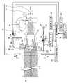
図1ないし図3は、本発明によるAF測距光学系を測量機に適用した第一の実施形態を示している。視準望遠鏡10は、図1に示すように、物体側(前方)から順に、対物レンズ11、正立光学系(ポロプリズム)12、焦点板13、及び接眼レンズ14を備えている。焦点板13上には、その中心に、視準の際の目印となる十字線ヘアライン(視準線)15が描かれている。対物レンズ11は光軸方向に可動であり、測定対象物16の距離に応じて位置調節することにより、その像を正しく焦点板13の対物レンズ11側の表面に結像させる。観察者は、この焦点板13上の像を接眼レンズ14を介して拡大観察する。
【0012】
視準望遠鏡10の対物レンズ11の後方には、光波距離計20の構成要素である送受光ミラー21と、測距光を反射し可視光を透過する波長選択フィルタ22とが順に配置されている。送受光ミラー21は、対物レンズ11の光軸上に位置する平行平面ミラーからなり、その対物レンズ11側の面が送光ミラー21a、波長選択フィルタ22側の面が受光ミラー21bを構成している。
【0013】
光波距離計20の発光素子23は、特定波長の測距光を発し、この測距光は、コリメータレンズ24及び固定ミラー25を介して、送光ミラー21aに入射する。送光ミラー21aに入射した測距光は、対物レンズ11の光軸上を進む。
【0014】
波長選択フィルタ22は、測定対象物16で反射し対物レンズ11を透過した測距光をさらに反射させて受光ミラー21bに戻す作用をし、受光ミラー21bは、その反射光を受光ファイバ26の入射端面26aに入射させる。27は、受光ファイバ26を保持するホルダであり、送受光ミラー21とともに、図示しない固定手段によって、対物レンズ11の後方の空間に固定されている。
【0015】
発光素子23と固定ミラー25の間の測距光路上には、切換ミラー28と送光用NDフィルタ29が配置されている。切換ミラー28は、発光素子23からの測距光を固定ミラー25に与えるか、直接受光ファイバ26の入射端面26aに与えるかの切換を行うものである。送光用NDフィルタ29は、測定対象物16に投光する測距光の光量調節用である。
【0016】
受光ファイバ26の出射端面26bと受光素子31との間には、集光レンズ32、受光用NDフィルタ33及びバンドパスフィルタ34が順に配置されている。受光素子31は、演算制御回路40に接続され、演算制御回路40は、切換ミラー28のアクチュエータ41と測距結果表示器42に接続されている。
【0017】
以上の光波距離計20は、周知のように、演算制御回路40がアクチュエータ41を介して切換ミラー28を駆動し、発光素子23からの測距光を固定ミラー25に与える状態と、受光ファイバ26の入射端面26aに直接与える状態とを作り出す。固定ミラー25に与えられた測距光は、上述のように、送光ミラー21aと対物レンズ11を介して測定対象物16に投光され、その反射光が対物レンズ11、波長選択フィルタ22及び受光ミラー21bを介して入射端面26aに入射する。そして、この測定対象物16で反射して入射端面26aに入射する測距光と、切換ミラー28を介して入射端面26aに直接与えられた内部参照光とが受光素子31によって受光され、演算制御回路40が測距光と内部参照光の位相差または時間差を検出し、測定対象物16迄の距離を演算して、測距結果表示器42に表示する。測距光と内部参照光の位相差または時間差による測距演算は周知である。
【0018】
ポロプリズム12には、光路分割面が形成されていて、その分割光路上に、位相差方式のAF検出ユニット(焦点検出手段)50が配置されている。このAF検出ユニット50は、焦点板13と光学的に等価な焦点検出面51の焦点状態、すなわち、合焦、非合焦、前ピン、後ピン、デフォーカス量を検出するもので、図2にその概念図を示す。焦点検出面51上に結像する対物レンズ11による物体像は、集光レンズ52及び基線長だけ離して配置した一対のセパレータレンズ(結像レンズ)53によって分割され、この分割された一対の像は一対のCCDラインセンサ54上に再結像する。ラインセンサ54は多数の光電変換素子を有し、各光電変換素子が、受光した物体像を光電変換して光電変換した電荷を積分(蓄積)し、積分した電荷をAFセンサデータとして出力し、演算制御回路40に入力する。演算制御回路40は、一対のAFセンサデータに基づいて、所定のデフォーカス演算によってデフォーカス量を算出し、レンズ駆動手段43を介して、対物レンズ11を合焦位置に移動させる。このようなデフォーカス演算は当業者周知である。演算制御回路40には、AF開始スイッチ44と測距開始スイッチ45が接続されている。
【0019】
以上のAF検出ユニット50は、各ラインセンサ54に結像する一対の像を基準に考えると、対物レンズ11上において異なる一対の瞳範囲11A、11Bを通過した光束によりラインセンサ54上に結像された一対の像でピント位置を検出することになる。瞳範囲11Aと11Bの瞳範囲の形状は、各セパレータレンズ53の近傍にそれぞれ配置するマスク55によって設定することができる。なお、図におけるハッチングは、この一対の瞳範囲に対応する部分を概念的に示している。
【0020】
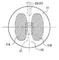
図3は、対物レンズ11上のこの瞳範囲11Aと11Bの位置関係、及び光波距離計20の送受光ミラー21と受光ファイバ26(ファイバフォルダ27)の位置関係を示している。瞳範囲11Aと11Bの位置、形状及び方向は、AF検出ユニット50の集光レンズ52、セパレータレンズ53、マスク55、ラインセンサ54の多数の光電変換素子より、AF性能を満足する値に定められているが、方向(対物レンズ11の中心に対する瞳範囲の方向)は比較的自由に設定することができる。そこで、本実施形態では、瞳範囲11Aと11Bの位置を、光波距離計20の送受光ミラー21と受光ファイバ26(ファイバフォルダ27)(及びこれらの支持部材)に干渉しないように定めたのである。別言すると、瞳範囲11Aと11Bの間のAF不感帯11C内に、送受光ミラー21と受光ファイバ26(ファイバフォルダ27)(及びこれらの支持部材)を配置したのである。特に、送受光ミラー21と受光ファイバ26(ファイバフォルダ27)(及びこれらの支持部材)を、対物レンズ11の光軸を通る直径方向に並べ、瞳範囲11Aと11Bをこの並び方向と平行な縦長に設定することにより、より簡単に、両者の干渉が生じないAF測距光学系を構成することができる。
【0021】
このように瞳範囲11Aと11Bの位置を定めることにより、正確な視準望遠鏡10の焦点検出が可能となり、精度の高い自動合焦ができる。仮に、光波距離計20の送受光ミラー21と受光ファイバ26(ファイバフォルダ27)(及びこれらの支持部材)が瞳範囲11Aと11Bに干渉すると、ラインセンサ54の多数の光電変換素子の個々に入射する光量にばらつきが発生するため、精度の高い自動合焦ができない。
【0022】
上記構成の本AF測距光学系の動作例を説明すると次の通りである。
第1ステップ
接眼レンズ14から測定対象物16を覗き、視準望遠鏡10の光軸を概ね測定対象物16に合致させる。
弟2ステップ
AF開始スイッチ44を押して上述のAF動作を実行し、対物レンズ11を合焦位置に移動させる。
第3ステップ
合焦状態で、接眼レンズ14を覗き、焦点板13の十字線ヘアライン15を正確に測定対象物16に一致させる。このように十字線ヘアライン15を正確に測定対象物16に一致させることにより、光波距離計20の測距光を正しく測定対象物16に投光することができる。
第4ステップ
測距開始スイッチ45を押して光波距離計20による上述の測距動作を実行し、測距結果表示器42に測距結果を表示する。
【0023】
図4、図5は、本発明によるAF測距光学系の第二の実施形態を示している。図1に示す測距光学系(光波距離計20)では、光波距離計20から送光される測距光の測定対象物16での反射光の集光効率を上げるために、対物レンズ11の焦点距離は短い方が有利である。なぜなら、測定点の送光径をφA、距離をL、対物レンズ11の焦点距離をfとすると、受光ファイバ位置での送光径像の大きさはφaは、φa=φA×f/Lで与えられ、fが小さい(短い)程、φaが小さくなるからである。受光ファイバの径は小さいため、fが十分小さければ、φAのすべてを取り込める。ところが、対物レンズ11の焦点距離を短くすると、図6に示すように、瞳範囲11Aと11Bの間隔が狭くなり、AF不感帯11Cに光波距離計20の送受光ミラー21と受光ファイバ26(ファイバフォルダ27)(及びその支持部材)を配置することが困難になる。すなわち、瞳範囲11Aと11Bと、送受光ミラー21と受光ファイバ26(ファイバフォルダ27)(及びその支持部材)が干渉してしまう。
【0024】
そこで本実施形態では、図4に示すように、対物レンズ11とポロプリズム12(AF検出ユニット50)との間に、負のパワーの焦点調節レンズ18を配設している。負のパワーの焦点調節レンズ18は、瞳範囲11Aと11Bの間隔を拡げ、AF不感帯11Cの大きさを大きくする作用を有する。このため、図5のように、瞳範囲11Aと11Bの間隔を拡げ、両者の間のAF不感帯11Cに、光波距離計20の送受光ミラー21と受光ファイバ26(ファイバフォルダ27)(及びその支持部材)を容易に配置することができる。この負の焦点調節レンズ18は、対物レンズ11に比して小型であるため、この負の焦点調節レンズ18をレンズ駆動手段43を介して光軸方向に駆動される視準望遠鏡10の焦点調節レンズとすることにより、AF系の駆動重量を軽減することができる。
【0025】
以上の負の焦点調節レンズ18による瞳範囲11Aと11Bの間隔を拡げる作用は、次のように説明することができる。対物レンズ11上のAF不感帯11Cの幅の大小は、AFユニットの瞳範囲を示すF値の大小で相対的に表される。すなわち、AF不感帯11Cの幅Dmmは、対物レンズ11の焦点距離をEmmとするとき、F=E/Dで表される。このため、対物レンズ11の焦点距離を短くする程、AFユニットの瞳範囲を示すF値を小さくしないと、十分なAF不感帯11Cの幅を確保することができない。これに対し、対物レンズ11に加えて、負の焦点調節レンズ18を配置すると、対物レンズ11と焦点調節レンズ18(対物系)の合成焦点距離は長くなり、その結果、AFユニットの瞳範囲を示すF値を小さくしなくても、AF不感帯11Cの幅を大きく確保することができる。
【0026】
この第二の実施形態の視準及び測距動作は、視準望遠鏡10の焦点調節が負の焦点調節レンズ18で行われることを除き、基本的に第一の実施形態と同様にして行うことができる。
【0027】
なお、正立光学系としてのポロプリズム12あるいはAFユニット50への分岐光学系は、種々の変形例が知られており、本発明は以上の実施例に限定されない。
【0028】
【発明の効果】
以上のように本発明は、光波距離計を有する測量機をAF化するにつき、位相差検出方式の焦点検出手段の対物レンズ上の一対の瞳範囲と、光波距離計の構成要素とが干渉しないようにしたので、AF性能を低下させることのないAF測距光学系を得ることができる。
【図面の簡単な説明】
【図1】本発明によるAF測距光学系を測量機に適用した第一の実施形態を示す系統接続図である。
【図2】図1のII矢視図であって、焦点検出手段(AFユニット、位相差方式焦点検出手段)の概念図である。
【図3】図1のIII‐III線から見た、焦点検出手段の対物レンズ上の一対の瞳範囲と、送受光ミラー及び受光ファイバとの位置関係を示す図である。
【図4】本発明によるAF測距光学系を測量機に適用した第二の実施形態を示す系統接続図である。
【図5】図4のV‐V線から見た、焦点検出手段の対物レンズ上の一対の瞳範囲と、送受光ミラー及び受光ファイバとの位置関係を示す図である。
【図6】図4のAF測距光学系において、対物レンズとAFユニットの間に負レンズが配置されていない場合の焦点検出手段の一対の瞳範囲と、送受光ミラー及び受光ファイバとの位置関係を示す、図3に対応する図である。
【符号の説明】
10 視準望遠鏡
11A 11B 瞳範囲
11C AF不感帯
12 ポロプリズム(正立光学系)
13 焦点板
14 接眼レンズ
15 十字線ヘアライン(視準線)
16 測定対象物
18 負のパワーの焦点調節レンズ
20 光波距離計
21 送受光ミラー
21a 送光ミラー
21b 受光ミラー
22 波長選択フィルタ
23 発光素子
24 コリメータレンズ
25 固定ミラー
26 受光ファイバ
26a 入射端面
26b 出射端面
27 ファイバフォルダ
28 切換ミラー
29 送光用NDフィルタ
31 受光素子
32 集光レンズ
33 受光用NDフィルタ
34 バンドパスフィルタ
40 演算制御回路
41 アクチュエータ
42 測距結果表示器
43 レンズ駆動手段
44 AF開始スイッチ
45 測距開始スイッチ
50 AF検出ユニット(位相差方式焦点検出手段)
51 焦点検出面
52 集光レンズ
53 セパレータレンズ
54 ラインセンサ
55 マスク[0001]
【Technical field】
The present invention relates to an AF distance measuring optical system having a distance measuring function and an AF function of a collimating telescope.
[0002]
[Prior art and its problems]
A surveying instrument such as a total station has a distance and angle measurement function, and the distance measurement is generally a light wave that calculates the distance from the phase difference or time difference between the distance measuring light projected on the measurement object and the internal reference light. This is done by a distance meter (EDM).
[0003]
On the other hand, the use of AF for collimating telescopes is also progressing in surveying instruments. A phase difference type AF device widely used as an AF device is a correlation (phase difference) between a pair of images formed by light beams that have passed through a pair of different pupil ranges set on an objective lens of a collimating telescope. ), And the collimating telescope is focused based on the detection result.
[0004]
However, when a phase difference type focus detection device is incorporated into a surveying instrument having a lightwave distance meter, the components of the lightwave distance meter interfere with a pair of pupil positions on the objective lens for focus detection, thereby detecting focus accuracy. There is a problem that the AF performance is lowered and the AF performance is lowered.
[0005]
OBJECT OF THE INVENTION
An object of the present invention is to obtain an AF distance measuring optical system in which the light wave distance meter does not deteriorate the AF performance based on the above problem awareness regarding the AF of the surveying instrument having the light wave distance meter.
[0006]
SUMMARY OF THE INVENTION
An AF distance measuring optical system according to the present invention includes a collimating telescope that collimates a measurement object; a light transmission system that transmits distance measuring light through the collimating telescope; and a reflected light from the measurement object. A light wave distance meter having a light receiving system; focus detection means for detecting the focus state via a collimating telescope; and control means for automatically adjusting the collimating telescope based on the focus state detected by the focus detection means; The focus detection means is a phase difference method that detects a focus position with a pair of images formed by light beams that have passed through a pair of different pupil ranges set on the objective lens of the collimating telescope. In addition to the focus detection means, the components of the optical wave rangefinder are provided at positions that do not interfere with the pair of pupil ranges of the phase difference focus detection means.
[0007]
According to another expression, the AF distance measuring optical system according to the present invention includes a collimating telescope that collimates a measurement object; a light transmission system that transmits distance measuring light through the collimating telescope; and a measurement object. An optical distance meter having a light receiving system for receiving the reflected light of the lens; a position for detecting a focus position by a pair of images formed by light beams passing through a pair of different pupil ranges set on the objective lens of the collimating telescope A phase difference type focus detection means; and a control means for automatically adjusting the collimating telescope based on a focus state detected by the phase difference type focus detection means. A pair of pupil ranges on the objective lens are set at positions that do not interfere with the components of the lightwave distance meter.
[0008]
In the collimating telescope, all or part of the objective lens can be a focus adjustment lens, and the focus adjustment lens can be driven in the optical axis direction for focus adjustment based on the focus state detected by the focus detection means. .
[0009]
As another aspect, it is preferable that the collimating telescope includes an optical system that extends a focal distance between the objective lens and the focus detection unit in addition to the objective lens. If there is an optical system that extends the focal length, the focal length of the objective lens is shortened to improve the light collection efficiency, and even if the ranging performance is improved, the pair of pupil ranges on the AF objective lens are sufficiently separated, It becomes easy to secure a space for arranging the elements of the optical distance meter. The optical system for extending the focal length can be most easily composed of a negative power focusing lens, and this negative power focusing lens is arranged in the direction of the optical axis based on the focus state detected by the focus detection means. To adjust the focus. As an element of the optical wave distance meter arranged in the space of the pair of pupil ranges, there is at least a reflecting member that constitutes the light transmission system of the optical wave distance meter located on the optical axis of the objective lens.
[0010]
In order to more easily avoid interference between the components of the optical rangefinder and the pair of pupil ranges, the components of the optical rangefinder are arranged in the diameter direction passing through the optical axis of the objective lens, and the pair of pupil ranges are parallel to this arrangement direction. It is preferable to set the vertical length.
[0011]
DETAILED DESCRIPTION OF THE INVENTION
1 to 3 show a first embodiment in which an AF distance measuring optical system according to the present invention is applied to a surveying instrument. As shown in FIG. 1, the
[0012]
Behind the
[0013]
The
[0014]
The
[0015]
On the distance measuring optical path between the
[0016]
A
[0017]
As described above, in the
[0018]
The
[0019]
The above
[0020]
FIG. 3 shows the positional relationship between the pupil ranges 11A and 11B on the
[0021]
By determining the positions of the pupil ranges 11A and 11B in this manner, it is possible to accurately detect the focus of the collimating
[0022]
An example of the operation of the AF distance measuring optical system having the above configuration will be described as follows.
The
The younger brother 2 step AF start switch 44 is pressed to execute the above-described AF operation, and the
In the third step in-focus state, the
The fourth step distance measurement start
[0023]
4 and 5 show a second embodiment of the AF distance measuring optical system according to the present invention. In the distance measuring optical system (light wave distance meter 20) shown in FIG. 1, in order to increase the collection efficiency of the reflected light from the
[0024]
Therefore, in the present embodiment, as shown in FIG. 4, a negative power
[0025]
The operation of expanding the distance between the pupil ranges 11A and 11B by the negative
[0026]
The collimation and ranging operations of the second embodiment are basically performed in the same manner as the first embodiment except that the collimating
[0027]
Various modifications of the
[0028]
【The invention's effect】
As described above, according to the present invention, when a surveying instrument having a lightwave distance meter is converted to AF, the pair of pupil ranges on the objective lens of the focus detection means of the phase difference detection method and the components of the lightwave distance meter do not interfere with each other. Since it did in this way, the AF ranging optical system which does not reduce AF performance can be obtained.
[Brief description of the drawings]
FIG. 1 is a system connection diagram showing a first embodiment in which an AF distance measuring optical system according to the present invention is applied to a surveying instrument.
2 is a conceptual diagram of focus detection means (AF unit, phase difference type focus detection means), as viewed in the direction of arrow II in FIG. 1;
FIG. 3 is a diagram showing a positional relationship between a pair of pupil ranges on an objective lens of a focus detection unit, a transmission / reception mirror, and a light reception fiber, as viewed from line III-III in FIG. 1;
FIG. 4 is a system connection diagram showing a second embodiment in which an AF distance measuring optical system according to the present invention is applied to a surveying instrument.
5 is a diagram showing a positional relationship between a pair of pupil ranges on the objective lens of the focus detection unit, a light transmitting / receiving mirror, and a light receiving fiber, as seen from the line VV in FIG. 4;
6 shows a pair of pupil ranges of a focus detection unit and positions of a light transmitting / receiving mirror and a light receiving fiber when a negative lens is not disposed between the objective lens and the AF unit in the AF distance measuring optical system of FIG. It is a figure corresponding to FIG. 3 which shows a relationship.
[Explanation of symbols]
10
13 Focusing
16 Measurement object 18
51
Claims (7)
Translated fromJapaneseこの視準望遠鏡を介して測距光を送光する送光系と、測定対象物からの反射光を受光する受光系とを有する光波距離計;
上記視準望遠鏡を介してその焦点状態を検出する焦点検出手段;及び
この焦点検出手段によって検出した焦点状態に基づいて上記視準望遠鏡を自動焦点調節する制御手段;
を備え、
上記焦点検出手段は、視準望遠鏡の対物レンズ上に設定された異なる一対の瞳範囲を通過した光束により結像された一対の像でピント位置を検出する位相差方式の焦点検出手段であり、
上記光波距離計の構成要素は、この位相差方式焦点検出手段の一対の瞳範囲と干渉しない位置に設けられていることを特徴とするAF測距光学系。A collimating telescope that collimates the measurement object;
A lightwave distance meter having a light transmission system for transmitting distance measuring light through the collimating telescope and a light receiving system for receiving reflected light from the measurement object;
Focus detecting means for detecting the focus state via the collimating telescope; and control means for automatically focusing the collimating telescope based on the focus state detected by the focus detecting means;
With
The focus detection means is a phase difference type focus detection means for detecting a focus position with a pair of images formed by light beams that have passed through a pair of different pupil ranges set on the objective lens of the collimating telescope,
2. The AF distance measuring optical system according to claim 1, wherein the components of the light wave distance meter are provided at positions that do not interfere with a pair of pupil ranges of the phase difference type focus detection means.
この視準望遠鏡を介して測距光を送光する送光系と、測定対象物からの反射光を受光する受光系とを有する光波距離計;
上記視準望遠鏡の対物レンズ上に設定された異なる一対の瞳範囲を通過した光束により結像された一対の像でピント位置を検出する位相差方式の焦点検出手段;及び
この位相差方式焦点検出手段によって検出した焦点状態に基づいて上記視準望遠鏡を自動焦点調節する制御手段;
を備え、
上記位相差方式焦点検出手段は、上記対物レンズ上の上記一対の瞳範囲を、上記光波距離計の構成要素と干渉しない位置に設定したことを特徴とするAF測距光学系。A collimating telescope that collimates the measurement object;
A lightwave distance meter having a light transmission system for transmitting distance measuring light through the collimating telescope and a light receiving system for receiving reflected light from the measurement object;
A phase difference type focus detection means for detecting a focus position with a pair of images formed by light beams passing through different pairs of pupil ranges set on the objective lens of the collimating telescope; and the phase difference type focus detection Control means for automatically focusing the collimating telescope based on the focus state detected by the means;
With
The AF distance measuring optical system according to claim 1, wherein the phase difference type focus detection means sets the pair of pupil ranges on the objective lens at positions where they do not interfere with components of the lightwave distance meter.
Priority Applications (3)
| Application Number | Priority Date | Filing Date | Title |
|---|---|---|---|
| JP2000066230AJP3752126B2 (en) | 2000-03-10 | 2000-03-10 | AF ranging optical system |
| US09/799,618US6480266B2 (en) | 2000-03-10 | 2001-03-07 | Autofocus distance-measuring optical system |
| DE10111444ADE10111444A1 (en) | 2000-03-10 | 2001-03-09 | Optical autofocus distance measuring system |
Applications Claiming Priority (1)
| Application Number | Priority Date | Filing Date | Title |
|---|---|---|---|
| JP2000066230AJP3752126B2 (en) | 2000-03-10 | 2000-03-10 | AF ranging optical system |
Publications (2)
| Publication Number | Publication Date |
|---|---|
| JP2001255459A JP2001255459A (en) | 2001-09-21 |
| JP3752126B2true JP3752126B2 (en) | 2006-03-08 |
Family
ID=18585618
Family Applications (1)
| Application Number | Title | Priority Date | Filing Date |
|---|---|---|---|
| JP2000066230AExpired - Fee RelatedJP3752126B2 (en) | 2000-03-10 | 2000-03-10 | AF ranging optical system |
Country Status (3)
| Country | Link |
|---|---|
| US (1) | US6480266B2 (en) |
| JP (1) | JP3752126B2 (en) |
| DE (1) | DE10111444A1 (en) |
Families Citing this family (34)
| Publication number | Priority date | Publication date | Assignee | Title |
|---|---|---|---|---|
| JP3892704B2 (en)* | 2001-10-30 | 2007-03-14 | ペンタックス株式会社 | Light wave rangefinder |
| US20060092314A1 (en)* | 2004-10-31 | 2006-05-04 | Silverstein D A | Autofocus using a filter with multiple apertures |
| JP4874641B2 (en)* | 2005-12-16 | 2012-02-15 | Hoya株式会社 | Camera with autofocus device |
| EP1934554A4 (en)* | 2006-05-02 | 2010-07-14 | Quality Vision Internat Inc | Laser range sensor system optics adapter and method |
| US9946922B2 (en) | 2009-01-15 | 2018-04-17 | Tokitae Llc | Photonic fence |
| US9182596B2 (en) | 2010-02-28 | 2015-11-10 | Microsoft Technology Licensing, Llc | See-through near-eye display glasses with the optical assembly including absorptive polarizers or anti-reflective coatings to reduce stray light |
| US20150309316A1 (en) | 2011-04-06 | 2015-10-29 | Microsoft Technology Licensing, Llc | Ar glasses with predictive control of external device based on event input |
| US8488246B2 (en) | 2010-02-28 | 2013-07-16 | Osterhout Group, Inc. | See-through near-eye display glasses including a curved polarizing film in the image source, a partially reflective, partially transmitting optical element and an optically flat film |
| US9223134B2 (en) | 2010-02-28 | 2015-12-29 | Microsoft Technology Licensing, Llc | Optical imperfections in a light transmissive illumination system for see-through near-eye display glasses |
| US9134534B2 (en) | 2010-02-28 | 2015-09-15 | Microsoft Technology Licensing, Llc | See-through near-eye display glasses including a modular image source |
| US9097890B2 (en) | 2010-02-28 | 2015-08-04 | Microsoft Technology Licensing, Llc | Grating in a light transmissive illumination system for see-through near-eye display glasses |
| US9129295B2 (en) | 2010-02-28 | 2015-09-08 | Microsoft Technology Licensing, Llc | See-through near-eye display glasses with a fast response photochromic film system for quick transition from dark to clear |
| US8477425B2 (en) | 2010-02-28 | 2013-07-02 | Osterhout Group, Inc. | See-through near-eye display glasses including a partially reflective, partially transmitting optical element |
| US9759917B2 (en) | 2010-02-28 | 2017-09-12 | Microsoft Technology Licensing, Llc | AR glasses with event and sensor triggered AR eyepiece interface to external devices |
| US9285589B2 (en) | 2010-02-28 | 2016-03-15 | Microsoft Technology Licensing, Llc | AR glasses with event and sensor triggered control of AR eyepiece applications |
| US9341843B2 (en) | 2010-02-28 | 2016-05-17 | Microsoft Technology Licensing, Llc | See-through near-eye display glasses with a small scale image source |
| US8467133B2 (en) | 2010-02-28 | 2013-06-18 | Osterhout Group, Inc. | See-through display with an optical assembly including a wedge-shaped illumination system |
| US20120249797A1 (en) | 2010-02-28 | 2012-10-04 | Osterhout Group, Inc. | Head-worn adaptive display |
| US9091851B2 (en) | 2010-02-28 | 2015-07-28 | Microsoft Technology Licensing, Llc | Light control in head mounted displays |
| US9097891B2 (en) | 2010-02-28 | 2015-08-04 | Microsoft Technology Licensing, Llc | See-through near-eye display glasses including an auto-brightness control for the display brightness based on the brightness in the environment |
| US10180572B2 (en) | 2010-02-28 | 2019-01-15 | Microsoft Technology Licensing, Llc | AR glasses with event and user action control of external applications |
| US9229227B2 (en) | 2010-02-28 | 2016-01-05 | Microsoft Technology Licensing, Llc | See-through near-eye display glasses with a light transmissive wedge shaped illumination system |
| US9128281B2 (en) | 2010-09-14 | 2015-09-08 | Microsoft Technology Licensing, Llc | Eyepiece with uniformly illuminated reflective display |
| WO2011106797A1 (en) | 2010-02-28 | 2011-09-01 | Osterhout Group, Inc. | Projection triggering through an external marker in an augmented reality eyepiece |
| US8472120B2 (en) | 2010-02-28 | 2013-06-25 | Osterhout Group, Inc. | See-through near-eye display glasses with a small scale image source |
| US9366862B2 (en) | 2010-02-28 | 2016-06-14 | Microsoft Technology Licensing, Llc | System and method for delivering content to a group of see-through near eye display eyepieces |
| US8482859B2 (en) | 2010-02-28 | 2013-07-09 | Osterhout Group, Inc. | See-through near-eye display glasses wherein image light is transmitted to and reflected from an optically flat film |
| DE102012004226B4 (en) | 2012-03-06 | 2022-01-13 | Sew-Eurodrive Gmbh & Co Kg | Method for calibrating a camera and subsequently determining a distance between the camera and an object |
| JP6344845B2 (en)* | 2014-04-14 | 2018-06-20 | リコーインダストリアルソリューションズ株式会社 | Laser distance measuring device |
| EP2977789A1 (en) | 2014-07-25 | 2016-01-27 | Nxp B.V. | Distance measurement |
| CN106210520B (en)* | 2015-11-05 | 2019-03-19 | 杭州舜立光电科技有限公司 | A kind of automatic focusing electronic eyepiece and system |
| JP2018056518A (en)* | 2016-09-30 | 2018-04-05 | 株式会社ニコン | Imaging element and focus adjustment device |
| JP2019113377A (en)* | 2017-12-22 | 2019-07-11 | パイオニア株式会社 | Detector |
| US11935258B2 (en) | 2021-03-08 | 2024-03-19 | Toyota Research Institute, Inc. | Range detection using machine learning combined with camera focus |
Family Cites Families (13)
| Publication number | Priority date | Publication date | Assignee | Title |
|---|---|---|---|---|
| JPS606114U (en)* | 1983-06-24 | 1985-01-17 | キヤノン株式会社 | focus detection device |
| US4935612A (en)* | 1986-05-16 | 1990-06-19 | Reichert Jung Optische Werks, A.G. | Autofocus system and method of using the same |
| CH674675A5 (en)* | 1987-10-23 | 1990-06-29 | Kern & Co Ag | |
| JPH04355390A (en)* | 1991-06-03 | 1992-12-09 | Nissan Motor Co Ltd | Distance measuring apparatus |
| KR960028223A (en)* | 1994-12-15 | 1996-07-22 | 나카사토 요시히코 | Phase difference detection method between image pairs |
| JP3708991B2 (en) | 1994-12-28 | 2005-10-19 | ペンタックス株式会社 | Inner focus telescope |
| DE19614235C2 (en) | 1995-04-10 | 2001-06-28 | Asahi Optical Co Ltd | Surveying instrument with auto focus system |
| JP3648514B2 (en) | 1995-04-26 | 2005-05-18 | ペンタックス株式会社 | Surveying device focus adjustment device |
| DE19713417C2 (en) | 1996-04-01 | 2000-12-14 | Asahi Optical Co Ltd | Focusing for a telescope system |
| US5988862A (en)* | 1996-04-24 | 1999-11-23 | Cyra Technologies, Inc. | Integrated system for quickly and accurately imaging and modeling three dimensional objects |
| US5923468A (en) | 1996-07-01 | 1999-07-13 | Asahi Kogaku Kogyo Kabushiki Kaisha | Surveying instrument having an automatic focusing device |
| JPH1184003A (en)* | 1997-09-04 | 1999-03-26 | Nikon Corp | Lightwave ranging device |
| JP3569426B2 (en)* | 1997-12-05 | 2004-09-22 | ペンタックス株式会社 | Reflecting member for surveying |
- 2000
- 2000-03-10JPJP2000066230Apatent/JP3752126B2/ennot_activeExpired - Fee Related
- 2001
- 2001-03-07USUS09/799,618patent/US6480266B2/ennot_activeExpired - Fee Related
- 2001-03-09DEDE10111444Apatent/DE10111444A1/ennot_activeWithdrawn
Also Published As
| Publication number | Publication date |
|---|---|
| DE10111444A1 (en) | 2001-09-13 |
| US6480266B2 (en) | 2002-11-12 |
| US20010021012A1 (en) | 2001-09-13 |
| JP2001255459A (en) | 2001-09-21 |
Similar Documents
| Publication | Publication Date | Title |
|---|---|---|
| JP3752126B2 (en) | AF ranging optical system | |
| JP3881498B2 (en) | Light wave rangefinder | |
| US6945657B2 (en) | Surveying instrument | |
| JP3723721B2 (en) | Lightwave distance finder and lightwave distance finder with AF function | |
| JP2001317938A (en) | Surveying instrument with lightwave distance meter | |
| US6580495B2 (en) | Surveying instrument having a phase-difference detection type focus detecting device and a beam-splitting optical system | |
| JP3634719B2 (en) | Lightwave ranging finder with AF function | |
| US6469777B2 (en) | Surveying instrument having an optical distance meter | |
| JP3718411B2 (en) | AF surveying machine | |
| JP3590565B2 (en) | Surveying instrument with lightwave distance meter | |
| US6677568B2 (en) | Surveying instrument having a phase-difference detection type focus detecting device | |
| JP3923996B2 (en) | Lightwave ranging finder with AF function | |
| JPH09243747A (en) | Distance measuring device | |
| JP3634772B2 (en) | Surveying instrument and surveying instrument having AF function | |
| JP3782702B2 (en) | Ghosting and flare prevention device for surveying instruments | |
| JP3911147B2 (en) | AF surveying machine | |
| JP2001324326A (en) | Surveying instrument with af function | |
| JPS62106424A (en) | Focus detection optical system | |
| JPH05173060A (en) | Focus detecting device | |
| JPS62115112A (en) | Focus detection optical system | |
| JPS62115113A (en) | Focus detection optical system | |
| JPH02183239A (en) | Camera |
Legal Events
| Date | Code | Title | Description |
|---|---|---|---|
| A621 | Written request for application examination | Free format text:JAPANESE INTERMEDIATE CODE: A621 Effective date:20040531 | |
| A711 | Notification of change in applicant | Free format text:JAPANESE INTERMEDIATE CODE: A711 Effective date:20050310 | |
| A977 | Report on retrieval | Free format text:JAPANESE INTERMEDIATE CODE: A971007 Effective date:20051116 | |
| TRDD | Decision of grant or rejection written | ||
| A01 | Written decision to grant a patent or to grant a registration (utility model) | Free format text:JAPANESE INTERMEDIATE CODE: A01 Effective date:20051129 | |
| A61 | First payment of annual fees (during grant procedure) | Free format text:JAPANESE INTERMEDIATE CODE: A61 Effective date:20051209 | |
| R150 | Certificate of patent or registration of utility model | Free format text:JAPANESE INTERMEDIATE CODE: R150 | |
| FPAY | Renewal fee payment (event date is renewal date of database) | Free format text:PAYMENT UNTIL: 20081216 Year of fee payment:3 | |
| FPAY | Renewal fee payment (event date is renewal date of database) | Free format text:PAYMENT UNTIL: 20091216 Year of fee payment:4 | |
| FPAY | Renewal fee payment (event date is renewal date of database) | Free format text:PAYMENT UNTIL: 20101216 Year of fee payment:5 | |
| FPAY | Renewal fee payment (event date is renewal date of database) | Free format text:PAYMENT UNTIL: 20101216 Year of fee payment:5 | |
| S111 | Request for change of ownership or part of ownership | Free format text:JAPANESE INTERMEDIATE CODE: R313111 | |
| FPAY | Renewal fee payment (event date is renewal date of database) | Free format text:PAYMENT UNTIL: 20101216 Year of fee payment:5 | |
| R350 | Written notification of registration of transfer | Free format text:JAPANESE INTERMEDIATE CODE: R350 | |
| FPAY | Renewal fee payment (event date is renewal date of database) | Free format text:PAYMENT UNTIL: 20101216 Year of fee payment:5 | |
| S111 | Request for change of ownership or part of ownership | Free format text:JAPANESE INTERMEDIATE CODE: R313113 | |
| FPAY | Renewal fee payment (event date is renewal date of database) | Free format text:PAYMENT UNTIL: 20101216 Year of fee payment:5 | |
| R350 | Written notification of registration of transfer | Free format text:JAPANESE INTERMEDIATE CODE: R350 | |
| LAPS | Cancellation because of no payment of annual fees |