JP3751638B2 - Separation layer pulse oximetry - Google Patents
Separation layer pulse oximetryDownload PDFInfo
- Publication number
- JP3751638B2 JP3751638B2JP52783396AJP52783396AJP3751638B2JP 3751638 B2JP3751638 B2JP 3751638B2JP 52783396 AJP52783396 AJP 52783396AJP 52783396 AJP52783396 AJP 52783396AJP 3751638 B2JP3751638 B2JP 3751638B2
- Authority
- JP
- Japan
- Prior art keywords
- electromagnetic
- detector
- patient
- wavelength
- emitter
- Prior art date
- Legal status (The legal status is an assumption and is not a legal conclusion. Google has not performed a legal analysis and makes no representation as to the accuracy of the status listed.)
- Expired - Fee Related
Links
- 238000002106pulse oximetryMethods0.000titleclaimsdescription11
- 238000000926separation methodMethods0.000title1
- QVGXLLKOCUKJST-UHFFFAOYSA-Natomic oxygenChemical compound[O]QVGXLLKOCUKJST-UHFFFAOYSA-N0.000claimsdescription30
- 230000005670electromagnetic radiationEffects0.000claimsdescription30
- 229910052760oxygenInorganic materials0.000claimsdescription30
- 239000001301oxygenSubstances0.000claimsdescription30
- 238000005259measurementMethods0.000claimsdescription26
- 239000008280bloodSubstances0.000claimsdescription15
- 210000004369bloodAnatomy0.000claimsdescription15
- 238000000034methodMethods0.000claimsdescription12
- 230000000694effectsEffects0.000claimsdescription7
- 230000000541pulsatile effectEffects0.000claimsdescription6
- 230000004044responseEffects0.000claimsdescription5
- 210000001519tissueAnatomy0.000description26
- 238000004364calculation methodMethods0.000description8
- 238000010521absorption reactionMethods0.000description7
- 238000010586diagramMethods0.000description7
- 230000000747cardiac effectEffects0.000description6
- 206010033675panniculitisDiseases0.000description4
- 210000004304subcutaneous tissueAnatomy0.000description4
- 102000001554HemoglobinsHuman genes0.000description3
- 108010054147HemoglobinsProteins0.000description3
- 238000002835absorbanceMethods0.000description3
- 230000008859changeEffects0.000description3
- 238000001228spectrumMethods0.000description3
- 238000007920subcutaneous administrationMethods0.000description3
- 210000001367arteryAnatomy0.000description2
- 238000010009beatingMethods0.000description2
- 235000013405beerNutrition0.000description2
- 238000001727in vivoMethods0.000description2
- 230000001965increasing effectEffects0.000description2
- 238000012544monitoring processMethods0.000description2
- 230000003287optical effectEffects0.000description2
- 230000037361pathwayEffects0.000description2
- 238000012545processingMethods0.000description2
- 229920006395saturated elastomerPolymers0.000description2
- 210000003462veinAnatomy0.000description2
- 208000000616HemoptysisDiseases0.000description1
- 206010047139VasoconstrictionDiseases0.000description1
- 230000009471actionEffects0.000description1
- 238000013459approachMethods0.000description1
- 238000000149argon plasma sinteringMethods0.000description1
- 230000008033biological extinctionEffects0.000description1
- 230000017531blood circulationEffects0.000description1
- 210000000988bone and boneAnatomy0.000description1
- 238000005094computer simulationMethods0.000description1
- 238000007796conventional methodMethods0.000description1
- 238000012937correctionMethods0.000description1
- 238000013461designMethods0.000description1
- 230000009977dual effectEffects0.000description1
- 230000001605fetal effectEffects0.000description1
- 210000003754fetusAnatomy0.000description1
- 230000001939inductive effectEffects0.000description1
- 230000031700light absorptionEffects0.000description1
- 210000003205muscleAnatomy0.000description1
- 238000002496oximetryMethods0.000description1
- 238000003672processing methodMethods0.000description1
- 230000005855radiationEffects0.000description1
- 239000000523sampleSubstances0.000description1
- 230000035945sensitivityEffects0.000description1
- 210000003491skinAnatomy0.000description1
- 230000025033vasoconstrictionEffects0.000description1
Images


Classifications
- A—HUMAN NECESSITIES
- A61—MEDICAL OR VETERINARY SCIENCE; HYGIENE
- A61B—DIAGNOSIS; SURGERY; IDENTIFICATION
- A61B5/00—Measuring for diagnostic purposes; Identification of persons
- A61B5/145—Measuring characteristics of blood in vivo, e.g. gas concentration or pH-value ; Measuring characteristics of body fluids or tissues, e.g. interstitial fluid or cerebral tissue
- A61B5/1455—Measuring characteristics of blood in vivo, e.g. gas concentration or pH-value ; Measuring characteristics of body fluids or tissues, e.g. interstitial fluid or cerebral tissue using optical sensors, e.g. spectral photometrical oximeters
- A61B5/14551—Measuring characteristics of blood in vivo, e.g. gas concentration or pH-value ; Measuring characteristics of body fluids or tissues, e.g. interstitial fluid or cerebral tissue using optical sensors, e.g. spectral photometrical oximeters for measuring blood gases
- G—PHYSICS
- G01—MEASURING; TESTING
- G01N—INVESTIGATING OR ANALYSING MATERIALS BY DETERMINING THEIR CHEMICAL OR PHYSICAL PROPERTIES
- G01N21/00—Investigating or analysing materials by the use of optical means, i.e. using sub-millimetre waves, infrared, visible or ultraviolet light
- G01N21/17—Systems in which incident light is modified in accordance with the properties of the material investigated
- G01N21/25—Colour; Spectral properties, i.e. comparison of effect of material on the light at two or more different wavelengths or wavelength bands
- G01N21/31—Investigating relative effect of material at wavelengths characteristic of specific elements or molecules, e.g. atomic absorption spectrometry
- G01N21/314—Investigating relative effect of material at wavelengths characteristic of specific elements or molecules, e.g. atomic absorption spectrometry with comparison of measurements at specific and non-specific wavelengths
- G—PHYSICS
- G01—MEASURING; TESTING
- G01N—INVESTIGATING OR ANALYSING MATERIALS BY DETERMINING THEIR CHEMICAL OR PHYSICAL PROPERTIES
- G01N21/00—Investigating or analysing materials by the use of optical means, i.e. using sub-millimetre waves, infrared, visible or ultraviolet light
- G01N21/17—Systems in which incident light is modified in accordance with the properties of the material investigated
- G01N21/47—Scattering, i.e. diffuse reflection
- G01N21/49—Scattering, i.e. diffuse reflection within a body or fluid
- A—HUMAN NECESSITIES
- A61—MEDICAL OR VETERINARY SCIENCE; HYGIENE
- A61B—DIAGNOSIS; SURGERY; IDENTIFICATION
- A61B2562/00—Details of sensors; Constructional details of sensor housings or probes; Accessories for sensors
- A61B2562/02—Details of sensors specially adapted for in-vivo measurements
- A61B2562/0233—Special features of optical sensors or probes classified in A61B5/00
- A61B2562/0242—Special features of optical sensors or probes classified in A61B5/00 for varying or adjusting the optical path length in the tissue
- A—HUMAN NECESSITIES
- A61—MEDICAL OR VETERINARY SCIENCE; HYGIENE
- A61B—DIAGNOSIS; SURGERY; IDENTIFICATION
- A61B5/00—Measuring for diagnostic purposes; Identification of persons
- A61B5/145—Measuring characteristics of blood in vivo, e.g. gas concentration or pH-value ; Measuring characteristics of body fluids or tissues, e.g. interstitial fluid or cerebral tissue
- A61B5/1455—Measuring characteristics of blood in vivo, e.g. gas concentration or pH-value ; Measuring characteristics of body fluids or tissues, e.g. interstitial fluid or cerebral tissue using optical sensors, e.g. spectral photometrical oximeters
- A61B5/14551—Measuring characteristics of blood in vivo, e.g. gas concentration or pH-value ; Measuring characteristics of body fluids or tissues, e.g. interstitial fluid or cerebral tissue using optical sensors, e.g. spectral photometrical oximeters for measuring blood gases
- A61B5/14552—Details of sensors specially adapted therefor
Landscapes
- Physics & Mathematics (AREA)
- Health & Medical Sciences (AREA)
- Life Sciences & Earth Sciences (AREA)
- Spectroscopy & Molecular Physics (AREA)
- Pathology (AREA)
- General Health & Medical Sciences (AREA)
- Analytical Chemistry (AREA)
- Chemical & Material Sciences (AREA)
- Immunology (AREA)
- General Physics & Mathematics (AREA)
- Biochemistry (AREA)
- Molecular Biology (AREA)
- Surgery (AREA)
- Animal Behavior & Ethology (AREA)
- Biophysics (AREA)
- Public Health (AREA)
- Veterinary Medicine (AREA)
- Engineering & Computer Science (AREA)
- Optics & Photonics (AREA)
- Medical Informatics (AREA)
- Heart & Thoracic Surgery (AREA)
- Biomedical Technology (AREA)
- Measurement Of The Respiration, Hearing Ability, Form, And Blood Characteristics Of Living Organisms (AREA)
- Investigating Or Analysing Materials By Optical Means (AREA)
Description
Translated fromJapanese発明の背景
1.発明の分野
本発明は、パルス酸素測定の原理で作動する機器に関し、特に、生体内の動脈血の酸素飽和度を非侵襲的に測定する機器に関する。
2.従来技術の説明
患者血液の酸素飽和度レベルの生体内測定器に、可視や電磁気スペクトルの赤外領域付近の光が使用されてきた。米国特許第5139025号(ルイス(Lewis)ら)や国際公開公報(PCT)WO第92/21283号(ルイス(Lewis)ら)には、静脈及び動脈両方の血液の酸素飽和度が少なくとも3つの電磁センサー領域を使用して推定されるスペクトル分光機器について述べられている。このような機器の欠点は、酸素飽和度の計算の精度が、例えば、濃度変化のような血液の飽和度以外の組織のパラメータの変化に対する計算の感度により制限されてしまうことである。ドイツ国特許第DE4303693号(ラル(Rall)ら)には、胎児への接続を意図とした発明の特定形状のデバイスにおける酸素計測定法の最良の手段として単一の光検出器をもつ複数の光センサーの使用が教示されている。
参照文献として開示する米国特許第4700708号(ニュー・ジュニア(New,Jr.)ら)では、患者の動脈血組織でないものによる光の散乱や吸収の最小化又は推定を試みる際に心臓周期中に検出した光強度の変化を分離することにより動脈酸素飽和度を計算している。パルス酸素測定法として知られるこの技術は、骨、皮膚、筋肉等に導入される動脈の多くを除くのに効果的であるが、検出した強度全体に対して検出した強度の比較的小さい変化が必要な信号部分であることから、信号捕捉計算回路が非常に精巧なものでなくてはならない、という欠点がある。また、計算された酸素飽和度値が、皮膚や表面組織層を含む異なった多くの組織層からの拍動的な信号に影響される、という欠点もある。多層の酸素飽和度値が他とは異なり得ることから、層全体の一般的な平均動脈酸素飽和度値のみを知るためには、通常、特定の組織層や組織層の範囲の動脈酸素飽和度を知ることが望ましい。特に、外側表面付近での流れの無い拍動的な信号を与えるために、血流停止のような幾つかの臨床条件が続けられ得る。
米国特許第5188108号(セッカー(Secker))では、多数のエミッタ/レシーバの組み合わせを与えるために複数のエミッタ及び/又はレシーバの使用が示唆されている。各々の組み合わせのためのエミッタ/レシーバの配置間隔が選択され、異なった放出波長を使用してこの組み合わせ同士の間に相当の光学的路長を与える。
発明の概要
本発明は、従来のシステムで引き起こされる制限を明確に補償する、特定の組織深度における動脈血の酸素飽和度レベルの決定のためのパルス酸素測定システムを提供することによって、従来の欠点を克服した。特に、本発明は、間隔をおいて配置した多数の検出器及び/又はエミッタを使用することによって、対象の組織の上方又は下方の組織の飽和度レベルを取り除き、特定範囲の組織層の動脈飽和度レベルを分離するパルス酸素測定による測定を可能にする。
本発明の1つの実施例に従って、パルス酸素計モニターとの使用のためのセンサーが:患者に接続するための患者インターフェースハウジング;患者の組織を透過する電磁放射線を放出し、組織によって散乱された電磁放射線を検出するための少なくとも3つのセンサー領域;電磁気エミッタと電磁気検出器との第2のペア(pair)の間の配置間隔とは異なった、電磁気エミッタと電磁気検出器との第1のペアの間の配置間隔;及び検出した電磁放射線に応答して患者の動脈酸素飽和度レベルを計算する手段、を含む。
2つの好適実施例に従って、センサー領域は、間隔をおいて別々に配置した第1及び第2のエミッタ領域と、検出器とを含み、各々のエミッタ領域は、少なくとも2つの別々の波長の光を生成でき、第1のエミッタ領域と検出器とが、エミッタ及び検出器の第1のペアに対応し、第2のエミッタ領域と検出器とが、エミッタ及び検出器の第2のペアに対応する。変形的に、センサー領域は、第1及び第2の検出器領域と、エミッタ領域とを含み、各々の検出器領域は、少なくとも2つの別々の波長の光を検出でき、エミッタ領域は、少なくとも2つの別々の波長値を有する前記の光を生成できる。
【図面の簡単な説明】
本発明の他の目的及び多くの利点は、添付の図面に関連して以下の詳細な説明によってより明らかとなる。なお、図面を通じて、同様の部位は同様の符号で表されている。
図1Aは、単一のエミッタと多数の検出器とを使用して本発明の基本原理を示す概念図である。
図2Bは、多数のエミッタと単一の検出器とを使用した変形例を示す。
図2は、患者接触要素の一部分の拡大図である。
図3は、生体内における本発明の作用を示す部分断面図である。
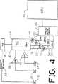
図4は、本発明を用いた作動システムの主構成成分を示す全てのブロック図である。
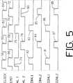
図5は、図4の実施例の作動のタイミング図である。
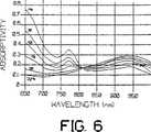
図6は、本発明の作動範囲内の多くの異なった酸素飽和度レベルの吸収性対波長のグラフである。
図7は、深部及び浅部の組織の測定に本発明の原理を使用して計算された酸素飽和度値と、本発明の原理を使用せずに得られた値とを含むグラフである。
好適実施例の詳細な説明
図1Aは、本発明の作動原理を示す概念図である。この例では、光吸収度Ubをもつ皮下組織レベル12において患者10の動脈血内における酸素飽和度のパーセンテージを測定することとする。光吸収度Uaをもつ皮膚又は表面組織14が、非侵襲性モニター及び測定システム(図示せず)との間にある。組織層12又は組織層14とは独立して動脈酸素飽和度が測定されるとみなされる。
第1の好適実施例に従って、エミッタ16が、2つの所定波長(例えば、660nm及び905nm)の可視及び赤外付近の範囲の電磁放射線を放出する。この例では、エミッタ16は単一で示される。しかし、必要に応じ、異なったエミッタを異なった所定波長のために使用してもよい。1つ以上のエミッタが使用される場合、これらは、単一のポイントソースを模擬するように極接近して配置されることが最も便利である。LEDがエミッタの好適なタイプである。エミッタ16からの信号は、図示のとおり、概ね経路18に沿って第1の検出器20へ、及び経路22に沿って第2の検出器24へと移動する。層12(吸収度Ub)内の経路18の長さは、L1で示され、層12内の経路22の長さはL2で示される。
検出器20は、エミッタ16からr1の距離をあけて配置され、検出器24は、r2の距離をあけて配置される。
図からわかるように、経路18及び経路22は共に、皮膚層14を2回、通過する。また、経路18及び経路22が近似的に同一の角度で皮膚層14を通過するので、経路22と経路18との間の主な差は、対象の組織層である皮下層12を通過する長さL1と長さL2との間の差である。したがって、経路L2と経路L1との間の吸収が、異なった間隔配置r2とr1とに対応する皮下層12(対象の組織層)に直接的に帰因し得る、と仮定できる。
皮膚層12を通じる経路長をl、皮下組織を通じる一層深い経路をL1及びL2で表して、検出器について考える。ここで、多数のエミッタが、図1Bに関連して以下で説明するように、単一の検出器へと放出することができる。ビールの法則(Beer's law)の公式に従うと、D120で検出される信号は、
I1=I0exp(-ual)・exp(-ubL1)・exp(-ual) (1)
で得られ、これは、皮膚層14を通じて2回、皮下組織12を通じて1回、移動する信号の減衰を説明し、ここで、
I1=D1における検出された光強度、
I0=エミッタEの放出した光強度
ua=層14の特有の吸収度、
ub=層12の特有の吸収度、
l=層14を通じる経路長、
L1=層12を通じる経路長、
をそれぞれ表す。
吸収係数は、吸収成分の濃度[C]とその吸光係数βとの積のように書き換えられる。この場合、[C]は、組織中の全てのヘモグロビンの濃度である。2つの層の異なった濃度を考慮すると、式(1)は、
I1=I0exp(-2βa[Ca]l-βb[Cb]L1) (2)
となる。静脈の影響を加味するために、β[C]を以下のように展開する。
β[C]=βart[C]art+βven[C]ven (3)
次に、パルス酸素測定の特徴を付加する。上層及び下層の動脈血濃度は心臓周期に従って時間と共に変化する点、及びこれら2つの層が異なった拍動(pulse)振幅を付加的に有する点、を考慮する。裏面の静脈血濃度は心臓周期と共に変化しない、と仮定する。適当な時間点(例えば、心臓周期の最大又は最小)において、式(3)を加味し、式(2)の対数をとると、
ln(I1(t1))=I0-2(βa,art[Ca(t1)]art+βa,ven[Ca]ven)l
-(βb,art[Cb(t1)]art+βb,ven[Cb]ven)L1 (4)
になる。第2の時間点で観察される信号を引くと、この式は、以下のように表される。
ln(I1(t1))-ln(I1(t2))=-2(βa,artΔ[Ca]art)l
-(βb,artΔ[Cb]art)L1 (5)
ここで、
Δ[C]art=[C(t1)]art-[C(t2)]art
である。表皮層の影響が、両方の検出器に同一の影響を与える、と仮定すると、検出器D2において観察される信号についても同様に表される。すなわち、
ln(I2(t1))-ln(I2(t2))=-2(βa,artΔ[Ca]art)l
-(βb,artΔ[Cb]art)L2 (6)
と表される。式(5)から式(6)を引くと、
[ln(I1(t1))-ln(I1(t2))]-[ln(I2(t1))-ln(I2(t1))]=
βb,artΔ[Cb]art(L2-L1) (7)
となる。ここで、皮膚層の影響は取り除かれている。最後に、測定は、第2の波長で繰り返される。2つの波長において得られる式(7)の比をとると、
R=([ln(I1(t1))-ln(I1(t2))]-[ln(I2(t1))-ln(I2(t1))])λ1/
([ln(I1(t1))-ln(I1(t2))]-[ln(I2(t1))-ln(I2(t1))])λ2
=βb,art,λ1Δ[Cb]art(L2-L1)λ1/
βb,art,λ2Δ[Cb]art(L2-L1)λ2 (8)
が得られる。式(8)は、第2の検出器が除かれた場合の在来のパルス酸素測定に相当する。従来の非散乱式の酸素測定モデルでは、平均経路長が2つの波長において等しい、と仮定され、これらは、式(8)から欠落される。しかし、このモデルは、平均経路長の比又は長さの差の比が、経験的に決定される修正因子として維持される場合、
R=βb,art,λ1/βb,art,λ2・ΔLλ1/ΔLλ2 (9)
である。ここで、
ΔL=L2-L1
である。在来のパルス酸素測定では、平均経路長の比は、有用な(しかし、制限される)飽和範囲にわたって安定する。しかし、この有用な範囲は、波長の適当な選択で、特定の重要な臨床的な範囲(例えば、70−100%飽和、又は40−60%飽和)を網羅するように設計できる。
吸光係数は、下記のような酸素飽和度の文字符号で書くことができる。
β=S・βoxy+(1-S)・βred (10)
ここで、
S=[O2Hb]/([O2Hb]+[Hb])
であり、
βoxyは、酸素ヘモグロビン(O2Hb)であり、
βredは、還元ヘモグロビン(Hb)である。
このことから、いずれもが、式(10)を式(9)へ応用する在来のパルス酸素測定法に従い、RでS(SpO2)を解くと、以下のようになる。
SpO2=[βredλ2-R・βredλ1]/
[R・(βoxyλ1-βredλ1)-βoxyλ2+βredλ2] (11)
式(11)では、ΔLの比は適当なβに取り込まれ、これらは、本発明の好適実施例に従って経験的に決定される。
この結果は、皮膚が拍動又は無拍動(例えば、血管収縮又は瀉血)の場合を無視し、皮膚層信号が測定値から除外される、という点で、在来の単一検出器パルス酸素測定演算とは異なる。なされた仮定の制限範囲内で、上方の皮膚層がシャントを造らず、より深部にある層が拍動し続ける限り、この演算は、深部の組織の動脈血飽和度にのみ関係する結果を与える。
エミッタ/検出器の第1のペア16、20(つまり、r1)と、エミッタ/検出器の第2のペア16、24(つまり、r2)との間隔は、lの4つの存在が全て近似的に等しいか又は少なくとも2つの検出器に影響する同等の対を有するように、皮膚の厚さの数倍以上大きく(つまり、r1、r2はdよりも非常に大きく)とるべきである。また、エミッタからの検出器の間隔も、十分な“深度”を探査するために十分大きくとるべきであり、この探査深度はこの間隔よりもやや小さい。2つの検出器は、相互に間隔をあけすぎるべきでなく、同等の皮膚の厚さの仮定が無視され得る。これら検出器が相互に接近した場合、ΔLは0となり、測定は不安定となる(式(9)を参照)。
また、より深い拍動組織の影響を除いて、皮膚の飽和度を明瞭に解法することも可能である。式(6)を式(5)から引く代わりに、式(5)にL2を掛け、式(6)にL1を掛けてから引くと、
L2・[Ln(I1(t1))-In(I1(t2))]-
L1・[ln(I2(t1))−ln(I2(t2))]=
2(L1-L2)lβa,artΔ[Ca]art (12)
となる。2つの波長では、式(12)は、
(L2・ln[I1(t1))/I1(t2)]-L1・ln[I2(t1)/I2(t2)])λ1/
(L2・ln[I1(t1))/I1(t2)]-L1・ln[I2(t1)/I2(t2)])λ2=
[(lΔL)λ1/(lΔL)λ2]・(βa,art,λ1/βa,art,λ2) (13)
となる。ここで、L/rで定義される経路長の乗数を用い、Mを皮下組織、mを皮膚層とする。ΔLがr1よりも非常に小さい場合、経路長の乗数が2つの検出器で同一とできる。このことから、
Mλ1=L1,λ1/r1はL2,λ1/r2に近似する;
mλ1=lλ1/d (14a)
Mλ2=L1,λ2/r1はL2,λ2/r2に近似する;
mλ2=lλ2/d (14b)
が得られる。これらを式(13)に代入すると、
R=(r2・ln[I1(t1)/I1(t2)]-r1・ln[I2(t1)/I2(t2)])λ1/
(r2・ln[I1(t1)/I1(t2)]-r1・ln[I2(t1)/I2(t2)])λ2=
mλ1/mλ2・βa,art,λ1/βa,art,λ2 (15)
といった一層有用な形にできる。皮下の計算については、mλ1/mλ2の比が経験的に決定された定数に取り込まれる。そして、前述の計算のように、経路長乗数の比は、制限されているが有用な飽和度の窓にわたって適切的に安定している。2つの検出器の位置決めは、ここでは、より重要であることから、好適なセンサーの実施例で再現される必要がある。SpO2の計算は、式(9)から(11)と同一のやり方である。
図1Bは、図1Aと同様の概念図であり、多数のエミッタ16、17と単一の検出器24を使用した本発明を示す。その動作が上説したものと類似することは、当業者にはわかることである。
図2は、本発明に使用する患者インターフェースデバイス26の好適な形態の斜視図である。平坦表面28が、モニター及び測定中に患者の皮膚に接触、配置される。所望とする場合、この位置は、粘着や他の周知の機械的手段を介して維持され得る。また、所望とする場合、表面28は、曲面を有してもよいし、可撓性又は剛性であってもよい。
平坦表面28が所定の位置にある時間中、エミッタ16、検出器20及び検出器24は、患者の皮膚に直接に接触している(図1も参照)。エミッタ16、検出器20及び検出器24の配置間隔は、上説したとおりである。
ワイヤー(図示せず)が、エミッタ16、検出器20及び検出器24をモニター機能を行う回路に電気的に接続している。
図3は、作動位置にある患者インターフェースデバイス26を示す部分断面図である。ケーブル32が、以下で説明するようなモニター回路との電気的信号の送受信を行う。その他の全ての構成要素上説したとおりである。
図4は、本発明に使用するモニター及び測定システムの全体を示すブロック図である。第1の好適実施例に従って、マルチプレクサ36及び2つの波長ドライバ34は、所望のチョップ周波数(例えば、1600Hz)で赤及び赤外線LED16を交互にオンする。これら赤及び赤外線信号は、検出器20、24によって検出され、電流-電圧増幅器38、40によって増幅される。相互コンダクタンス38、40の出力は、DMUX42によってデマルチプレクスされ、検出器D1(20)、D2(24)の各々の第1及び第2の波長信号を生成し、生成した信号は、積分増幅器49、51、53、55及びライン50、52、54、56を通じて送られる。これら第1及び第2の波長信号は、アナログ/デジタルコンバータ46によってデジタル化される。デジタル化した信号は、動脈酸素飽和度を計算するためのCPU48へ送信される。参考文献としてのPCT/US94/03546に、制御電子技術の好適な機器が開示されている。所望とする場合、変形的な周知の制御電子機器が使用できる。
上説したように、深い組織の特性を所望とする場合、CPU48は、予め経験的に決定したβred、λ2、βred、λ1、βoxy、λ2、βoxy、λ1を一定とし、式(8)を使用してR、式(11)を使用してSpO2を計算する。浅い組織の特性を所望とする場合、CPU48は、式(15)を使用してR,式(11)を使用してSpO2を計算する。
好適実施例に従って、CPU48は、参考文献としての米国特許第4869254号、同第5078136号、同第4911167号、同第4934372号、同第4802486号及び同第4928692号に説明される信号処理技術のいずれかを使用して、信号D1、λ1;D1、λ2;D2、λ1;D2、λ2からの動脈パルスを識別する。
また、Rが、心臓周期中に発生する最大及び最小強度を使用して式(8)、(15)で決定されるが、心臓周期の他の点も使用でき、それは、上記のPCT/US94/03546で説明される誘導信号処理技術を使用する近接デジタル点を含む。
好適実施例に従って、1つの波長が電磁気スペクトルの赤の部分(例えば、660nm)から選択され、もう1つの波長が電磁気スペクトルの赤外線付近の部分(例えば、900nm)から選択される。精密な波長値は、応用に従った設計的選択である。胎児の動脈酸素飽和度を検出するためのセンサーでの好適な波長の組は、参照文献としての米国特許出願番号第08/221911号に開示されるように、735nm、905nmである。
図5は、図4の装置のタイミング図である。パルス58、60、62、64を含んだクロック信号が、パターン生成器44(図4も参照)によって発生される。これらクロックパルスは、好適に、約1600Hzの割合で発生される。クロックパルスの各々は、パルス66、68、70、72で示されるようなエミッタ16の出力をトリガーする。第1の波長は、タイミング信号74、76に対応して2回、放出される。その後、第2の波長が、タイミング信号78、80に対応して2回、放出される。
検出器20によって受信されるような第1の波長からの信号は、時間82、83の間、ライン50を介してDMUX42によってアナログ/デジタルコンバータ46へゲートされる。検出器24によって受信されるような第1の波長により発生される信号は、時間81、86においてライン54にわたってゲートされる。同様に、第2の波長の放出からの信号は、それぞれ、時間84、85及び時間87、88において検出器20、24からライン52、54にわたってゲートされる。受信した信号は、デジタル形状へと変換され、酸素飽和度レベルの計算のため、CPU48へ送信される。
図6は、エミッタ16の波長に対する多種の動脈血飽和度レベルを示すグラフである。本発明の好適な波長は、約660nmと約905nmである。しかし、本発明が他の波長を使用しても行い得ることは、当業者には明らかである。
図7は、単一の検出器のための従来の技術と、図1に示すような第1及び第2の検出器とを使用して計算した動脈酸素飽和度のコンピューターモデルから得られたデータを示すグラフである。図示のように、深いものの比が、在来のシステムからの比に非常に接近していることがわかる。
本発明は、少なくとも2つのわかっている異なった波長の光を放出する単一のエミッタ領域16と、第1及び第2の間隔をあけて配置した検出器領域20、24とを有する装置を参照して主として説明してきたが、3つのセンサー領域が、図1Bに示すように、単一の検出器領域と、第1及び第2のわかっている異なった波長の光を放出する第1及び第2の間隔をあけて配置したエミッタ領域とを有することで達成し得ることもわかる。好適実施例に従って、信号は、標準の時間信号マルチプレクス技術を使用して、エミッタによって送信され、検出器によって検出されるが、所望の場合、他の信号マルチプレクス技術が変形的に使用され得る(例えば、周波数マルチプレクス)。また、異なった組織層の間での増加した分解能は、センサー領域の数を増加すれば達成し得る。例えば、半ダース又はそれ以上の二重波長エミッタ領域が、単一の検出器と共に組み合わされて使用され得る。また、センサー領域は、直線又は曲線の線形的なアレイで配列されてもよく、2次元的なアレイで配置されてもよい。異なったエミッタ/検出器の配置間隔のペアの各々は、開示したように、異なったパルス酸素測定信号処理方法を使用して酸素飽和度を計算するために使用されてもよく、これら多数の飽和度値は、センサー領域下の組織層を映像化するために、又はこれら組織層に関する他の所望の情報を得るために処理される。
本発明の好適な形態が説明されてきたが、当業者が、添付の請求の範囲内で他の実施例を推考できることは明らかである。Background of the Invention The present invention relates to instruments that operate on the principle of pulse oximetry, and more particularly to instruments that noninvasively measure the oxygen saturation of in-vivo arterial blood.
2. 2. Description of the Prior Art Light in the infrared region of the visible or electromagnetic spectrum has been used for in-vivo measuring devices for oxygen saturation levels in patient blood. In US Pat. No. 5,139,025 (Lewis et al.) And International Publication (PCT) WO 92/21283 (Lewis et al.), The oxygen saturation of blood in both veins and arteries is at least 3 electromagnetic A spectroscopic instrument is described that is estimated using the sensor area. The disadvantage of such an instrument is that the accuracy of oxygen saturation calculation is limited by the sensitivity of the calculation to changes in tissue parameters other than blood saturation, such as concentration changes. German Patent No. DE 4303669 (Rall et al.) Describes a plurality of devices with a single photodetector as the best means of oximeter measurement in a particular shaped device of the invention intended for connection to the fetus. The use of an optical sensor is taught.
U.S. Pat. No. 4,700,708 (New, Jr. et al.), Which is disclosed as a reference, detects during the cardiac cycle when attempting to minimize or estimate light scattering and absorption by non-arterial blood tissue of a patient. The arterial oxygen saturation is calculated by separating the changes in light intensity. This technique, known as pulse oximetry, is effective in removing many arteries introduced into bones, skin, muscles, etc., but there is a relatively small change in detected intensity relative to the overall detected intensity. Since it is a necessary signal part, there is a drawback that the signal acquisition calculation circuit must be very sophisticated. Another disadvantage is that the calculated oxygen saturation value is affected by the pulsatile signal from many different tissue layers, including the skin and surface tissue layers. Since the multilayer oxygen saturation values can be different from others, it is usually the case to know only the general mean arterial oxygen saturation value for the entire layer, arterial oxygen saturation for a specific tissue layer or range of tissue layers It is desirable to know. In particular, some clinical conditions such as blood flow arrest can be continued to provide a pulsatile signal with no flow near the outer surface.
US Pat. No. 5,188,108 (Secker) suggests the use of multiple emitters and / or receivers to provide multiple emitter / receiver combinations. The emitter / receiver spacing for each combination is selected and different emission wavelengths are used to provide a substantial optical path length between the combinations.
SUMMARY OF THE INVENTION The present invention provides a pulse oximetry system for the determination of arterial oxygen saturation levels at specific tissue depths that clearly compensates for the limitations caused by conventional systems. Overcame the conventional drawbacks. In particular, the present invention eliminates tissue saturation levels above or below the tissue of interest by using a number of spaced detectors and / or emitters, and arterial saturation of a range of tissue layers. Allows measurement by pulse oximetry to separate the degree level.
In accordance with one embodiment of the present invention, a sensor for use with a pulse oximeter monitor: a patient interface housing for connection to a patient; an electromagnetic radiation that emits electromagnetic radiation that is transmitted through the patient's tissue and is scattered by the tissue At least three sensor regions for detecting radiation; a first pair of electromagnetic emitters and electromagnetic detectors different from the spacing between the second pairs of electromagnetic emitters and electromagnetic detectors; And a means for calculating a patient's arterial oxygen saturation level in response to the detected electromagnetic radiation.
According to two preferred embodiments, the sensor region includes first and second emitter regions spaced apart and a detector, each emitter region receiving at least two separate wavelengths of light. A first emitter region and detector corresponding to a first pair of emitter and detector, and a second emitter region and detector corresponding to a second pair of emitter and detector. . Alternatively, the sensor region includes first and second detector regions and an emitter region, each detector region being capable of detecting light of at least two separate wavelengths, the emitter region being at least 2 The light having two separate wavelength values can be generated.
[Brief description of the drawings]
Other objects and many advantages of the present invention will become more apparent from the following detailed description when taken in conjunction with the accompanying drawings. In addition, the same site | part is represented with the same code | symbol through drawing.
FIG. 1A is a conceptual diagram illustrating the basic principle of the present invention using a single emitter and multiple detectors.
FIG. 2B shows a variation using multiple emitters and a single detector.
FIG. 2 is an enlarged view of a portion of the patient contacting element.
FIG. 3 is a partial cross-sectional view showing the action of the present invention in a living body.
FIG. 4 is an all block diagram showing the main components of the operating system using the present invention.
FIG. 5 is a timing diagram of the operation of the embodiment of FIG.
FIG. 6 is a graph of absorbance versus wavelength for many different oxygen saturation levels within the operating range of the present invention.
FIG. 7 is a graph that includes oxygen saturation values calculated using the principles of the present invention for deep and shallow tissue measurements and values obtained without using the principles of the present invention.
Detailed Description of the Preferred Embodiment FIG. 1A is a conceptual diagram illustrating the operating principle of the present invention. In this example, we will measure the percentage of oxygen saturation in the arterial blood of
In accordance with the first preferred embodiment,
The
As can be seen, both
Consider the detector, where l is the path length through the
I1 = I0 exp (-ua l) · exp (-ub L1 ) · exp (-ua l) (1)
Which explains the attenuation of the signal traveling twice through the
I1 = detected light intensity at D1 ,
I0 = light intensity emitted by emitter E
ua = specific absorption of
ub = specific absorption of
l = path length through
L1 = path length through
Respectively.
The absorption coefficient is rewritten as a product of the concentration [C] of the absorption component and its absorption coefficient β. In this case, [C] is the concentration of all hemoglobin in the tissue. Considering the different concentrations of the two layers, equation (1) is
I1 = I0 exp (-2βa [Ca ] l-βb [Cb ] L1 ) (2)
It becomes. In order to take into account the effect of veins, β [C] is expanded as follows.
β [C] = βart [C]art + βven [C]ven (3)
Next, the feature of pulse oximetry is added. Consider the fact that the upper and lower arterial blood concentrations change with time according to the cardiac cycle, and that these two layers additionally have different pulse amplitudes. Assume that the backside venous blood concentration does not change with the cardiac cycle. At an appropriate time point (for example, the maximum or minimum of the cardiac cycle), taking into account equation (3) and taking the logarithm of equation (2):
ln (I1 (t1 )) = I0 -2 (βa, art [Ca (t1 )]art + βa, ven [Ca ]ven ) l
-(βb, art [Cb (t1 )]art + βb, ven [Cb ]ven ) L1 (4)
become. Subtracting the signal observed at the second time point, this equation is expressed as:
ln (I1 (t1 ))-ln (I1 (t2 )) =-2 (βa, art Δ [Ca ]art ) l
-(βb, art Δ [Cb ]art ) L1 (5)
here,
Δ [C]art = [C (t1 )]art- [C (t2 )]art
It is. Assuming that the effect of the skin layer has the same effect on both detectors, the signal observed at detector D2 is similarly expressed. That is,
ln (I2 (t1 ))-ln (I2 (t2 )) =-2 (βa, art Δ [Ca ]art ) l
-(βb, art Δ [Cb ]art ) L2 (6)
It is expressed. Subtracting equation (6) from equation (5)
[ln (I1 (t1 ))-ln (I1 (t2 ))]-[ln (I2 (t1 ))-ln (I2 (t1 ))] =
βb, art Δ [Cb ]art (L2 -L1 ) (7)
It becomes. Here, the effect of the skin layer has been removed. Finally, the measurement is repeated at the second wavelength. Taking the ratio of equation (7) obtained at two wavelengths,
R = ([ln (I1 (t1 ))-ln (I1 (t2 ))]-[ln (I2 (t1 ))-ln (I2 (t1 ))])λ1 /
([ln (I1 (t1 ))-ln (I1 (t2 ))]-[ln (I2 (t1 ))-ln (I2 (t1 ))])λ2
= Βb, art, λ1 Δ [Cb ]art (L2 -L1 )λ1 /
βb, art, λ2 Δ [Cb ]art (L2 -L1 )λ2 (8)
Is obtained. Equation (8) corresponds to a conventional pulse oximetry when the second detector is removed. In conventional non-scattering oximetry models, it is assumed that the average path length is equal at the two wavelengths, and these are omitted from equation (8). However, this model can be used if the average path length ratio or length difference ratio is maintained as a correction factor that is determined empirically.
R = βb, art, λ1 / βb, art, λ2・ ΔLλ1 / ΔLλ2 (9)
It is. here,
ΔL = L2 -L1
It is. In conventional pulse oximetry,the ratio of mean path length is useful (but limited to)you stable over a saturated range. However, the usefulrange,in a suitable choice of wavelengths, certain important clinicalrange (e.g., 70-100% saturated, or 40-60% saturation) Rucan be designed to cover.
The extinction coefficient can be written with the following character code for oxygen saturation.
β = S · βoxy + (1-S) · βred (10)
here,
S = [O2 Hb] / ([O2 Hb] + [Hb])
And
βoxy is oxygen hemoglobin (O2 Hb)
βred is reduced hemoglobin (Hb).
From this, either solves S (Sp O2 ) with R according to the conventional pulse oximetry method applying Equation (10) to Equation (9), and the following results.
Sp O2 = [βredλ2 -R ・ βredλ1 ] /
[R ・ (βoxyλ1 -βredλ1 ) -βoxyλ2 + βredλ2 ] (11)
In equation (11), the ratio of ΔL is incorporated into the appropriate β, which are determined empirically according to the preferred embodiment of the present invention.
This result ignores the case where the skin is beating or non-pulsating (eg, vasoconstriction or hemoptysis), and the skin layer signal is excluded from the measurements. It is different from measurement calculation. As long as the upper skin layer does not create a shunt and the deeper layers continue to beat within the limits of the assumptions made, this operation gives a result that is only related to the arterial saturation of the deep tissue.
The spacing between the first emitter /
It is also possible to solve the skin saturation clearly without the influence of deeper beating tissue. Instead of subtracting equation (6) from equation (5), multiplying equation (5) by L2, multiplying equation (6) by L1, and then subtracting:
L2・ [Ln (I1 (t1 ))-In (I1 (t2 ))]-
L1 [[ln (I2 (t1))-ln (I2 (t2))] =
2 (L1 -L2 ) lβa, art Δ [Ca ]art (12)
It becomes. For two wavelengths, equation (12) is
(L2・ ln [I1 (t1 )) / I1 (t2 )]-L1・ ln [I2 (t1 ) / I2 (t2 )]) λ1 /
(L2 ln [I1 (t1 )) / I1 (t2 )]-L1 ln [I2 (t1 ) / I2 (t2 )]) λ2 =
[(lΔL)λ1 / (lΔL)λ2 ] ・ (βa, art, λ 1 / βa, art, λ 2 ) (13)
It becomes. Here, a path length multiplier defined by L / r is used, and M is a subcutaneous tissue and m is a skin layer. If ΔL is much smaller than r1 , the path length multiplier can be the same for the two detectors. From this,
Mλ1 = L1, λ1 / r1 approximates L2, λ1 / r2 ;
mλ1 = lλ1 / d (14a)
Mλ2 = L1, λ2 / r1 approximates L2, λ2 / r2 ;
mλ2 = lλ2 / d (14b)
Is obtained. Substituting these into equation (13) gives
R = (r2 · ln [I1 (t1 ) / I1 (t2 )]-r1 · ln [I2 (t1 ) / I2 (t2 )]) λ1 /
(r2 · ln [I1 (t1 ) / I1 (t2 )]-r1 · ln [I2 (t1 ) / I2 (t2 )]) λ2 =
mλ1 / mλ2・ βa, art, λ1 / βa, art, λ2 (15)
It can be made a more useful form. For the subcutaneous calculation, the ratio of mλ1 / mλ2 is taken into account for the empirically determined constant. And as in the previous calculations, the ratio of path length multipliers is adequately stable over a limited but useful saturation window. Since the positioning of the two detectors is more important here, it needs to be reproduced in a preferred sensor embodiment. The calculation of Sp O2 is the same way as in equations (9) to (11).
FIG. 1B is a conceptual diagram similar to FIG. 1A, illustrating the present invention using
FIG. 2 is a perspective view of a preferred form of
During the time that the
Wires (not shown) electrically connect
FIG. 3 is a partial cross-sectional view showing the
FIG. 4 is a block diagram showing the entire monitor and measurement system used in the present invention. In accordance with the first preferred embodiment,
As described above, when a deep tissue characteristic is desired, the
In accordance with the preferred embodiment, the
Also, R is determined in equations (8), (15) using the maximum and minimum intensities that occur during the cardiac cycle, but other points in the cardiac cycle can also be used, which is the PCT / US94 above. Including proximity digital points using inductive signal processing techniques described in / 03546.
In accordance with the preferred embodiment, one wavelength is selected from the red portion of the electromagnetic spectrum (eg, 660 nm) and the other wavelength is selected from the infrared portion of the electromagnetic spectrum (eg, 900 nm). The precise wavelength value is a design choice according to the application. A preferred set of wavelengths in a sensor for detecting fetal arterial oxygen saturation is 735 nm, 905 nm, as disclosed in US patent application Ser. No. 08 / 221,911 as a reference.
FIG. 5 is a timing diagram of the apparatus of FIG. A clock
The signal from the first wavelength as received by the
FIG. 6 is a graph showing various arterial blood saturation levels versus
FIG. 7 shows data obtained from a computer model of arterial oxygen saturation calculated using conventional techniques for a single detector and the first and second detectors as shown in FIG. It is a graph which shows. As can be seen, the ratio of the deep ones is very close to the ratio from the conventional system.
The present invention refers to an apparatus having a
While the preferred form of the invention has been described, it will be apparent to one skilled in the art that other embodiments may be envisaged within the scope of the appended claims.
Claims (9)
Translated fromJapanesea.患者の組織に向けて電磁放射線を放出し、組織によって散乱される電磁放射線を検出する)、少なくとも3つの電磁気エレメントを含む、患者に接続するための患者インターフェースであって、
前記電磁気エレメントのうちの少なくとも一つが、患者の組織に向けて電磁放射線を放出するための電磁気エミッタであり、
前記電磁気エレメントのうちの少なくとも一つが、前記組織で反射した電磁気放射線を検出するための電磁気検出器であり、
前記電磁気エミッタと前記電磁気検出器との第1の組み合わせにおいて、前記電磁気エミッタと前記電磁気検出器とが第1の配置間隔で配置され、この第1の組み合わせにおいて、前記電磁放射線の第1の経路長が与えられ、
前記電磁気エミッタと前記電磁気検出器との第2の組み合わせにおいて、前記電磁気エミッタと前記電磁気検出器とが第2の配置間隔で配置され、この第2の組み合わせにおいて、前記電磁放射線の第2の経路長が与えられ、
前記第2の経路長が前記第1の経路長と異なる、
ところの患者インターフェース、及び
b.検出した電磁放射線に応答して患者の動脈酸素飽和度レベルを計算するための手段であって、この手段が、前記患者の表面組織層の下の組織層での動脈酸素飽和度値が得られるように、前記患者の表面組織層の拍動信号の影響を取り除くアルゴリズムを使用する、ところの手段、
を含む装置。A pulse oximetry device for calculating arterial oxygen saturation,
a. A patient interface for connecting to a patient, comprising at least three electromagnetic elements, emitting electromagnetic radiation towards the patient's tissue and detecting electromagnetic radiation scattered by the tissue)
At least one of the electromagnetic elements is an electromagnetic emitter for emitting electromagnetic radiation toward a patient's tissue;
At least one of the electromagnetic elements is an electromagnetic detector for detecting electromagnetic radiation reflected by the tissue;
In the first combination of the electromagnetic emitter and the electromagnetic detector, the electromagnetic emitter and the electromagnetic detector are arranged at a first arrangement interval, and in this first combination, the first path of the electromagnetic radiation Given a length,
In the second combination of the electromagnetic emitter and the electromagnetic detector, the electromagnetic emitter and the electromagnetic detector are arranged at a second arrangement interval, and in this second combination, the second path of the electromagnetic radiation. Given a length,
The second path length is different from the first path length;
A patient interface, and b. Means for calculating a patient's arterial oxygen saturation level in response to detected electromagnetic radiation, wherein the means obtains an arterial oxygen saturation value at a tissue layer below the surface tissue layer of the patient Means using an algorithm to remove the influence of the pulsatile signal of the surface tissue layer of the patient,
Including the device.
前記患者インターフェース上に配列される3つ以上の電磁気エレメントをさらに含む、装置。An apparatus according to claim 1, comprising:
The apparatus further comprising three or more electromagnetic elements arranged on the patient interface.
前記の少なくとも3つの電磁気エレメントは、各々少なくとも2つの独立した波長の光を生成できる別々に間隔をあけて配置された第1及び第2の電磁気エミッタと、電磁気検出器とを含み、
前記第1の電磁気エミッタと前記電磁気検出器とが、前記電磁気エレメントの前記第1の組み合わせに対応し、
前記第2の電磁気エミッタと前記電磁気検出器とが、前記電磁気エレメントの前記第2の組み合わせに対応する、
ところの装置。An apparatus according to claim 1, comprising:
The at least three electromagnetic elements each include first and second electromagnetic emitters spaced apart, each capable of generating at least two independent wavelengths of light, and an electromagnetic detector;
The first electromagnetic emitter and the electromagnetic detector correspond to the first combination of the electromagnetic elements;
The second electromagnetic emitter and the electromagnetic detector correspond to the second combination of the electromagnetic elements;
But the device.
前記の少なくとも3つの電磁気エレメントは、各々少なくとも2つの別々の波長値の光を検出できる第1及び第2の電磁気検出器と、少なくとも2つの別々の波長値を有する前記光を生成できる電磁気エミッタとを含み、
前記電磁気エミッタと前記第1の電磁気検出器が、前記電磁気エレメントの前記第1の組み合わせに対応し、
前記電磁気エミッタと前記第2の電磁気検出器とが、前記電磁気エレメントの前記第2の組み合わせに対応する、
ところの装置。An apparatus according to claim 1, comprising:
The at least three electromagnetic elements each include first and second electromagnetic detectors capable of detecting light of at least two separate wavelength values, and an electromagnetic emitter capable of generating the light having at least two separate wavelength values; Including
The electromagnetic emitter and the first electromagnetic detector correspond to the first combination of the electromagnetic elements;
The electromagnetic emitter and the second electromagnetic detector correspond to the second combination of electromagnetic elements;
But the device.
a.前記患者の測定位置で動脈パルス波面の到達時間を決定する工程、
b.前記患者の前記測定位置に第1の波長の電磁放射線を放出する工程、
c.前記測定位置から第1の距離に位置した第1の電磁気検出器で前記第1の波長の電磁放射線の強度を測定する工程、
d.前記測定位置から第2の距離に位置した第2の電磁気検出器で前記第1の波長の電磁放射線の強度を測定する工程、
e.前記患者の前記測定位置で第2の波長の電磁放射線を放出する工程、
f.前記測定位置から前記第1の距離に位置した前記第1の電磁気検出器で前記第2の波長の電磁放射線の強度を測定する工程、
g.前記測定位置から前記第2の距離に位置した前記第2の電磁気検出器で前記第2の波長の電磁放射線の強度を測定する工程、及び
h.前記第1の電磁気検出器及び前記第2の電磁気検出器で測定した前記第1の波長の強度を使用し且つ前記第1の電磁気検出器及び前記第2の電磁気検出器で測定した前記第2の波長の強度を使用し、前記患者の静脈血の血液特性レベルを取り除き、第2の所定の組織深度から拍動信号の影響を取り除くアルゴリズムを用いて、対象の第1の所定の組織深度での血液特性レベルを決定する工程、
を含む方法。A method for measuring blood characteristics of a patient's blood,
a. Determining the arrival time of the arterial pulse wavefront at the measurement location of the patient;
b. Emitting electromagnetic radiation of a first wavelength to the measurement location of the patient;
c. Measuring the intensity of electromagnetic radiation of the first wavelength with a first electromagnetic detector located at a first distance from the measurement position;
d. Measuring the intensity of the electromagnetic radiation of the first wavelength with a second electromagnetic detector located at a second distance from the measurement position;
e. Emitting electromagnetic radiation of a second wavelength at the measurement location of the patient;
f. Measuring the intensity of electromagnetic radiation of the second wavelength with the first electromagnetic detector located at the first distance from the measurement position;
g. Measuring the intensity of electromagnetic radiation of the second wavelength with the second electromagnetic detector located at the second distance from the measurement position; and h. The second intensity measured using the first electromagnetic detector and the second electromagnetic detector using the intensity of the first wavelength measured by the first electromagnetic detector and the second electromagnetic detector. At a first predetermined tissue depth of the subject using an algorithm that removes the blood characteristic level of the venous blood of the patient and removes the effect of the pulsatile signal from the second predetermined tissue depth. Determining the blood property level of
Including methods.
a.前記患者の前記測定位置で動脈パルス波面の到達時間を決定する工程、
b.前記患者の前記測定位置に第1の波長の電磁放射線を放出する工程、
c.前記測定位置から第1の距離に位置した第1の電磁気検出器で前記第1の波長の電磁放射線の振幅を測定する工程、
d.前記測定位置から第2の距離に位置した第2の電磁気検出器で前記第1の波長の電磁放射線の振幅を測定する工程、
e.前記患者の前記測定位置で第2の波長の電磁放射線を放出する工程、
f.前記測定位置から前記第1の距離に位置した前記第1の電磁気検出器で前記第2の波長の電磁放射線の振幅を測定する工程、
g.前記測定位置から前記第2の距離に位置した前記第2の電磁気検出器で前記第2の波長の電磁放射線の振幅を測定する工程、及び
h.前記第1の電磁気検出器及び前記第2の電磁気検出器で測定した前記第1の波長の振幅を使用し且つ前記第1の電磁気検出器及び前記第2の電磁気検出器で測定した前記第2の波長の振幅を使用し、第2の所定の組織深度から拍動信号の影響を取り除くアルゴリズムを用いて、対象の第1の所定の組織深度での動脈酸素飽和度レベルを計算する工程、
を含む方法。A method for measuring arterial oxygen saturation level at a patient measurement location, comprising:
a. Determining the arrival time of the arterial pulse wavefront at the measurement location of the patient;
b. Emitting electromagnetic radiation of a first wavelength to the measurement location of the patient;
c. Measuring the amplitude of the electromagnetic radiation of the first wavelength with a first electromagnetic detector located at a first distance from the measurement position;
d. Measuring the amplitude of electromagnetic radiation of the first wavelength with a second electromagnetic detector located at a second distance from the measurement position;
e. Emitting electromagnetic radiation of a second wavelength at the measurement location of the patient;
f. Measuring an amplitude of electromagnetic radiation of the second wavelength with the first electromagnetic detector located at the first distance from the measurement position;
g. Measuring an amplitude of electromagnetic radiation of the second wavelength with the second electromagnetic detector located at the second distance from the measurement position; and h. The second measured by the first electromagnetic detector and the second electromagnetic detector using the amplitude of the first wavelength measured by the first electromagnetic detector and the second electromagnetic detector. Calculating an arterial oxygen saturation level at the first predetermined tissue depth of interest using an algorithm that removes the effects of the pulsatile signal from the second predetermined tissue depth using an amplitude of
Including methods.
前記の計算する工程が、前記患者の静脈血の酸素飽和度レベルを取り除く工程をさらに含む、
ところの方法。The method of claim6 , comprising:
The calculating step further comprises removing an oxygen saturation level of the patient's venous blood;
The way.
前記第1の距離及び前記第2の距離が、対象の前記所定の組織深度での測定を最適化するために選択される、
ところの方法。The method of claim6 , comprising:
The first distance and the second distance are selected to optimize measurement of the subject at the predetermined tissue depth;
The way.
a.患者の組織に向けて電磁放射線を放出し、組織によって散乱される電磁放射線を検出する)、少なくとも3つの電磁気エレメントを含む、患者に接続するための患者インターフェースであって、
前記電磁気エレメントのうちの少なくとも一つが、患者の組織に向けて電磁放射線を放出するための電磁気エミッタであり、
前記電磁気エレメントのうちの少なくとも一つが、前記組織で反射した電磁気放射線を検出するための電磁気検出器であり、
前記電磁気エミッタと前記電磁気検出器との第1の組み合わせにおいて、前記電磁気エミッタと前記電磁気検出器とが第1の配置間隔で配置され、この第1の組み合わせにおいて、前記電磁放射線の第1の経路長が与えられ、
前記電磁気エミッタと前記電磁気検出器との第2の組み合わせにおいて、前記電磁気エミッタと前記電磁気検出器とが第2の配置間隔で配置され、この第2の組み合わせにおいて、前記電磁放射線の第2の経路長が与えられ、
前記第2の経路長が前記第1の経路長と異なる、
ところの患者インターフェース、及び
b.第2の所定の組織深度から拍動信号の影響を取り除くアルゴリズムを用いて、対象の第1の所定の組織深度での、検出した電磁放射線に応答して患者の動脈酸素飽和度レベルを計算するための手段、
を含む装置。A pulse oximeter device for calculating arterial oxygen saturation,
a. A patient interface for connecting to a patient, comprising at least three electromagnetic elements, emitting electromagnetic radiation towards the patient's tissue and detecting electromagnetic radiation scattered by the tissue)
At least one of the electromagnetic elements is an electromagnetic emitter for emitting electromagnetic radiation toward a patient's tissue;
At least one of the electromagnetic elements is an electromagnetic detector for detecting electromagnetic radiation reflected by the tissue;
In the first combination of the electromagnetic emitter and the electromagnetic detector, the electromagnetic emitter and the electromagnetic detector are arranged at a first arrangement interval, and in this first combination, the first path of the electromagnetic radiation Given a length,
In the second combination of the electromagnetic emitter and the electromagnetic detector, the electromagnetic emitter and the electromagnetic detector are arranged at a second arrangement interval, and in this second combination, the second path of the electromagnetic radiation. Given a length,
The second path length is different from the first path length;
A patient interface, and b. An arterial oxygen saturation level of the patient is calculated in response to the detected electromagnetic radiation at the first predetermined tissue depth of the subject using an algorithm that removes the effects of the pulsatile signal from the second predetermined tissue depth. Means for
Including the device.
Applications Claiming Priority (4)
| Application Number | Priority Date | Filing Date | Title |
|---|---|---|---|
| US08/403,642US5524617A (en) | 1995-03-14 | 1995-03-14 | Isolated layer pulse oximetry |
| US403,642 | 1995-03-14 | ||
| CA002215163ACA2215163C (en) | 1995-03-14 | 1996-03-14 | Isolated layer pulse oximetry |
| PCT/US1996/003536WO1996028085A1 (en) | 1995-03-14 | 1996-03-14 | Isolated layer pulse oximetry |
Publications (2)
| Publication Number | Publication Date |
|---|---|
| JPH11501848A JPH11501848A (en) | 1999-02-16 |
| JP3751638B2true JP3751638B2 (en) | 2006-03-01 |
Family
ID=39672030
Family Applications (1)
| Application Number | Title | Priority Date | Filing Date |
|---|---|---|---|
| JP52783396AExpired - Fee RelatedJP3751638B2 (en) | 1995-03-14 | 1996-03-14 | Separation layer pulse oximetry |
Country Status (6)
| Country | Link |
|---|---|
| US (2) | US5524617A (en) |
| EP (1) | EP0812148B1 (en) |
| JP (1) | JP3751638B2 (en) |
| CA (2) | CA2591551A1 (en) |
| DE (1) | DE69632628T2 (en) |
| WO (1) | WO1996028085A1 (en) |
Families Citing this family (170)
| Publication number | Priority date | Publication date | Assignee | Title |
|---|---|---|---|---|
| US5902235A (en)* | 1989-03-29 | 1999-05-11 | Somanetics Corporation | Optical cerebral oximeter |
| US5575284A (en) | 1994-04-01 | 1996-11-19 | University Of South Florida | Portable pulse oximeter |
| US5524617A (en)* | 1995-03-14 | 1996-06-11 | Nellcor, Incorporated | Isolated layer pulse oximetry |
| US5995856A (en)* | 1995-11-22 | 1999-11-30 | Nellcor, Incorporated | Non-contact optical monitoring of physiological parameters |
| DE19640807A1 (en)* | 1996-10-02 | 1997-09-18 | Siemens Ag | Noninvasive optical detection of oxygen supply to e.g. brain or liver |
| US6018673A (en) | 1996-10-10 | 2000-01-25 | Nellcor Puritan Bennett Incorporated | Motion compatible sensor for non-invasive optical blood analysis |
| JP3365227B2 (en)* | 1996-10-25 | 2003-01-08 | 花王株式会社 | Method and apparatus for measuring optical properties of skin surface condition |
| US5830137A (en)* | 1996-11-18 | 1998-11-03 | University Of South Florida | Green light pulse oximeter |
| US5935076A (en)* | 1997-02-10 | 1999-08-10 | University Of Alabama In Huntsville | Method and apparatus for accurately measuring the transmittance of blood within a retinal vessel |
| US5776060A (en)* | 1997-02-20 | 1998-07-07 | University Of Alabama In Huntsville | Method and apparatus for measuring blood oxygen saturation within a retinal vessel with light having several selected wavelengths |
| WO1999063883A1 (en) | 1998-06-11 | 1999-12-16 | S.P.O. Medical Equipment Ltd. | Physiological stress detector device and method |
| IL121079A0 (en) | 1997-06-15 | 1997-11-20 | Spo Medical Equipment Ltd | Physiological stress detector device and method |
| CA2303803A1 (en)* | 1997-06-17 | 1998-12-23 | Respironics, Inc. | Fetal oximetry system and sensor |
| EP1405593B1 (en)* | 1997-09-05 | 2011-08-10 | Seiko Epson Corporation | Optical diagnostic measurement device |
| WO1999026528A1 (en)* | 1997-11-26 | 1999-06-03 | Somanetics Corporation | Method and apparatus for monitoring fetal cerebral oxygenation during childbirth |
| JP3794449B2 (en)* | 1998-04-07 | 2006-07-05 | 株式会社島津製作所 | Optical measuring device |
| WO2000000080A1 (en)* | 1998-06-26 | 2000-01-06 | Triphase Medical Ltd. | A device for evaluating blood system properties |
| US6061584A (en)* | 1998-10-28 | 2000-05-09 | Lovejoy; David A. | Pulse oximetry sensor |
| ATE404110T1 (en) | 1998-11-18 | 2008-08-15 | Lea Medizintechnik Gmbh | DEVICE FOR THE NON-INVASIVE DETERMINATION OF OXYGEN CONVERSION IN TISSUES |
| US6615061B1 (en)* | 1998-11-23 | 2003-09-02 | Abbott Laboratories | Optical sensor having a selectable sampling distance for determination of analytes |
| US6353226B1 (en)* | 1998-11-23 | 2002-03-05 | Abbott Laboratories | Non-invasive sensor capable of determining optical parameters in a sample having multiple layers |
| US7047054B2 (en)* | 1999-03-12 | 2006-05-16 | Cas Medical Systems, Inc. | Laser diode optical transducer assembly for non-invasive spectrophotometric blood oxygenation monitoring |
| US6675031B1 (en) | 1999-04-14 | 2004-01-06 | Mallinckrodt Inc. | Method and circuit for indicating quality and accuracy of physiological measurements |
| US8224412B2 (en) | 2000-04-17 | 2012-07-17 | Nellcor Puritan Bennett Llc | Pulse oximeter sensor with piece-wise function |
| EP1274343B1 (en) | 2000-04-17 | 2012-08-15 | Nellcor Puritan Bennett LLC | Pulse oximeter sensor with piece-wise function |
| EP1301119B1 (en)* | 2000-07-21 | 2005-06-15 | Universität Zürich | Probe and apparatus for measuring cerebral hemodynamics and oxygenation |
| US6529752B2 (en)* | 2001-01-17 | 2003-03-04 | David T. Krausman | Sleep disorder breathing event counter |
| US6748254B2 (en) | 2001-10-12 | 2004-06-08 | Nellcor Puritan Bennett Incorporated | Stacked adhesive optical sensor |
| US6839580B2 (en)* | 2001-12-06 | 2005-01-04 | Ric Investments, Inc. | Adaptive calibration for pulse oximetry |
| US7221969B2 (en)* | 2002-02-27 | 2007-05-22 | Neurophysics Corporation | Method and apparatus for determining cerebral oxygen saturation |
| US7003337B2 (en)* | 2002-04-26 | 2006-02-21 | Vivascan Corporation | Non-invasive substance concentration measurement using and optical bridge |
| US8175666B2 (en)* | 2002-04-26 | 2012-05-08 | Grove Instruments, Inc. | Three diode optical bridge system |
| WO2004010844A2 (en) | 2002-07-26 | 2004-02-05 | Cas Medical Systems, Inc. | Method for spectrophotometric blood oxygenation monitoring |
| US7190986B1 (en) | 2002-10-18 | 2007-03-13 | Nellcor Puritan Bennett Inc. | Non-adhesive oximeter sensor for sensitive skin |
| DE10333075B4 (en)* | 2003-07-21 | 2011-06-16 | Siemens Ag | Method and device for training adjustment in sports, especially in running |
| US20050049467A1 (en)* | 2003-08-28 | 2005-03-03 | Georgios Stamatas | Method for assessing pigmented skin |
| WO2005099564A1 (en)* | 2003-11-14 | 2005-10-27 | Tsinghua University | An apparatus of and method for measuring the parameter of the blood oxygen metabolism in human tissue |
| US7435214B2 (en)* | 2004-01-29 | 2008-10-14 | Cannuflow, Inc. | Atraumatic arthroscopic instrument sheath |
| US7162288B2 (en) | 2004-02-25 | 2007-01-09 | Nellcor Purtain Bennett Incorporated | Techniques for detecting heart pulses and reducing power consumption in sensors |
| US7194293B2 (en) | 2004-03-08 | 2007-03-20 | Nellcor Puritan Bennett Incorporated | Selection of ensemble averaging weights for a pulse oximeter based on signal quality metrics |
| JP4515148B2 (en)* | 2004-05-17 | 2010-07-28 | セイコーインスツル株式会社 | Biological information measuring apparatus and biological information measuring method |
| US7887492B1 (en) | 2004-09-28 | 2011-02-15 | Impact Sports Technologies, Inc. | Monitoring device, method and system |
| US20060079794A1 (en)* | 2004-09-28 | 2006-04-13 | Impact Sports Technologies, Inc. | Monitoring device, method and system |
| US20060253010A1 (en)* | 2004-09-28 | 2006-11-09 | Donald Brady | Monitoring device, method and system |
| US7647083B2 (en) | 2005-03-01 | 2010-01-12 | Masimo Laboratories, Inc. | Multiple wavelength sensor equalization |
| US8055321B2 (en) | 2005-03-14 | 2011-11-08 | Peter Bernreuter | Tissue oximetry apparatus and method |
| US7865223B1 (en)* | 2005-03-14 | 2011-01-04 | Peter Bernreuter | In vivo blood spectrometry |
| US8396526B2 (en) | 2005-05-12 | 2013-03-12 | Cas Medical Systems, Inc. | Method for spectrophotometric blood oxygenation monitoring |
| US7657295B2 (en) | 2005-08-08 | 2010-02-02 | Nellcor Puritan Bennett Llc | Medical sensor and technique for using the same |
| US7657294B2 (en) | 2005-08-08 | 2010-02-02 | Nellcor Puritan Bennett Llc | Compliant diaphragm medical sensor and technique for using the same |
| US7590439B2 (en) | 2005-08-08 | 2009-09-15 | Nellcor Puritan Bennett Llc | Bi-stable medical sensor and technique for using the same |
| US7657293B2 (en) | 2005-09-08 | 2010-02-02 | Vioptix Inc. | Method for monitoring viability of tissue flaps |
| US20070060808A1 (en) | 2005-09-12 | 2007-03-15 | Carine Hoarau | Medical sensor for reducing motion artifacts and technique for using the same |
| US7869850B2 (en) | 2005-09-29 | 2011-01-11 | Nellcor Puritan Bennett Llc | Medical sensor for reducing motion artifacts and technique for using the same |
| US7904130B2 (en) | 2005-09-29 | 2011-03-08 | Nellcor Puritan Bennett Llc | Medical sensor and technique for using the same |
| US8092379B2 (en) | 2005-09-29 | 2012-01-10 | Nellcor Puritan Bennett Llc | Method and system for determining when to reposition a physiological sensor |
| US7899510B2 (en) | 2005-09-29 | 2011-03-01 | Nellcor Puritan Bennett Llc | Medical sensor and technique for using the same |
| US7486979B2 (en) | 2005-09-30 | 2009-02-03 | Nellcor Puritan Bennett Llc | Optically aligned pulse oximetry sensor and technique for using the same |
| US7483731B2 (en) | 2005-09-30 | 2009-01-27 | Nellcor Puritan Bennett Llc | Medical sensor and technique for using the same |
| US8233954B2 (en) | 2005-09-30 | 2012-07-31 | Nellcor Puritan Bennett Llc | Mucosal sensor for the assessment of tissue and blood constituents and technique for using the same |
| US7881762B2 (en) | 2005-09-30 | 2011-02-01 | Nellcor Puritan Bennett Llc | Clip-style medical sensor and technique for using the same |
| US7555327B2 (en) | 2005-09-30 | 2009-06-30 | Nellcor Puritan Bennett Llc | Folding medical sensor and technique for using the same |
| US8062221B2 (en) | 2005-09-30 | 2011-11-22 | Nellcor Puritan Bennett Llc | Sensor for tissue gas detection and technique for using the same |
| WO2007048039A2 (en)* | 2005-10-21 | 2007-04-26 | Cas Medical Systems, Inc. | Method and apparatus for spectrophotometric based oximetry |
| US7477924B2 (en) | 2006-05-02 | 2009-01-13 | Nellcor Puritan Bennett Llc | Medical sensor and technique for using the same |
| US8073518B2 (en) | 2006-05-02 | 2011-12-06 | Nellcor Puritan Bennett Llc | Clip-style medical sensor and technique for using the same |
| US7522948B2 (en) | 2006-05-02 | 2009-04-21 | Nellcor Puritan Bennett Llc | Medical sensor and technique for using the same |
| US20130035569A1 (en)* | 2006-05-03 | 2013-02-07 | Nellcor Puritan Bennett Llc | Method and apparatus for hemometry |
| KR101041727B1 (en)* | 2006-05-31 | 2011-06-14 | 고쿠리츠 다이가꾸 호우진 시즈오까 다이가꾸 | Storage medium recording optical measuring device, optical measuring method, and optical measuring program |
| US8145288B2 (en) | 2006-08-22 | 2012-03-27 | Nellcor Puritan Bennett Llc | Medical sensor for reducing signal artifacts and technique for using the same |
| US8219170B2 (en) | 2006-09-20 | 2012-07-10 | Nellcor Puritan Bennett Llc | System and method for practicing spectrophotometry using light emitting nanostructure devices |
| US8175671B2 (en) | 2006-09-22 | 2012-05-08 | Nellcor Puritan Bennett Llc | Medical sensor for reducing signal artifacts and technique for using the same |
| US8396527B2 (en) | 2006-09-22 | 2013-03-12 | Covidien Lp | Medical sensor for reducing signal artifacts and technique for using the same |
| US8195264B2 (en) | 2006-09-22 | 2012-06-05 | Nellcor Puritan Bennett Llc | Medical sensor for reducing signal artifacts and technique for using the same |
| US7869849B2 (en) | 2006-09-26 | 2011-01-11 | Nellcor Puritan Bennett Llc | Opaque, electrically nonconductive region on a medical sensor |
| US7574245B2 (en) | 2006-09-27 | 2009-08-11 | Nellcor Puritan Bennett Llc | Flexible medical sensor enclosure |
| US8123695B2 (en)* | 2006-09-27 | 2012-02-28 | Nellcor Puritan Bennett Llc | Method and apparatus for detection of venous pulsation |
| US7890153B2 (en) | 2006-09-28 | 2011-02-15 | Nellcor Puritan Bennett Llc | System and method for mitigating interference in pulse oximetry |
| US7796403B2 (en) | 2006-09-28 | 2010-09-14 | Nellcor Puritan Bennett Llc | Means for mechanical registration and mechanical-electrical coupling of a faraday shield to a photodetector and an electrical circuit |
| US7476131B2 (en) | 2006-09-29 | 2009-01-13 | Nellcor Puritan Bennett Llc | Device for reducing crosstalk |
| US8175667B2 (en) | 2006-09-29 | 2012-05-08 | Nellcor Puritan Bennett Llc | Symmetric LED array for pulse oximetry |
| US7684842B2 (en) | 2006-09-29 | 2010-03-23 | Nellcor Puritan Bennett Llc | System and method for preventing sensor misuse |
| US7680522B2 (en) | 2006-09-29 | 2010-03-16 | Nellcor Puritan Bennett Llc | Method and apparatus for detecting misapplied sensors |
| US8068891B2 (en) | 2006-09-29 | 2011-11-29 | Nellcor Puritan Bennett Llc | Symmetric LED array for pulse oximetry |
| US8265723B1 (en) | 2006-10-12 | 2012-09-11 | Cercacor Laboratories, Inc. | Oximeter probe off indicator defining probe off space |
| US20080297764A1 (en)* | 2006-11-13 | 2008-12-04 | Weinmann Gerate Fur Medizin Gmbh + Co. Kg | Sensor for determining body parameters |
| US20080208019A1 (en)* | 2007-02-22 | 2008-08-28 | Jerusalem College Of Technology | Modified Pulse Oximetry Technique For Measurement Of Oxygen Saturation In Arterial And Venous Blood |
| US8221326B2 (en)* | 2007-03-09 | 2012-07-17 | Nellcor Puritan Bennett Llc | Detection of oximetry sensor sites based on waveform characteristics |
| US8265724B2 (en) | 2007-03-09 | 2012-09-11 | Nellcor Puritan Bennett Llc | Cancellation of light shunting |
| US8280469B2 (en) | 2007-03-09 | 2012-10-02 | Nellcor Puritan Bennett Llc | Method for detection of aberrant tissue spectra |
| US8109882B2 (en)* | 2007-03-09 | 2012-02-07 | Nellcor Puritan Bennett Llc | System and method for venous pulsation detection using near infrared wavelengths |
| US7894869B2 (en) | 2007-03-09 | 2011-02-22 | Nellcor Puritan Bennett Llc | Multiple configuration medical sensor and technique for using the same |
| US8229530B2 (en)* | 2007-03-09 | 2012-07-24 | Nellcor Puritan Bennett Llc | System and method for detection of venous pulsation |
| EP2139383B1 (en) | 2007-03-27 | 2013-02-13 | Masimo Laboratories, Inc. | Multiple wavelength optical sensor |
| US8374665B2 (en) | 2007-04-21 | 2013-02-12 | Cercacor Laboratories, Inc. | Tissue profile wellness monitor |
| US9622694B2 (en) | 2007-06-20 | 2017-04-18 | Vioptix, Inc. | Measuring cerebral oxygen saturation |
| US8380272B2 (en)* | 2007-12-21 | 2013-02-19 | Covidien Lp | Physiological sensor |
| US8352004B2 (en) | 2007-12-21 | 2013-01-08 | Covidien Lp | Medical sensor and technique for using the same |
| US8346328B2 (en) | 2007-12-21 | 2013-01-01 | Covidien Lp | Medical sensor and technique for using the same |
| US8366613B2 (en) | 2007-12-26 | 2013-02-05 | Covidien Lp | LED drive circuit for pulse oximetry and method for using same |
| US8577434B2 (en) | 2007-12-27 | 2013-11-05 | Covidien Lp | Coaxial LED light sources |
| US8452364B2 (en) | 2007-12-28 | 2013-05-28 | Covidien LLP | System and method for attaching a sensor to a patient's skin |
| US8442608B2 (en) | 2007-12-28 | 2013-05-14 | Covidien Lp | System and method for estimating physiological parameters by deconvolving artifacts |
| US8092993B2 (en) | 2007-12-31 | 2012-01-10 | Nellcor Puritan Bennett Llc | Hydrogel thin film for use as a biosensor |
| US8897850B2 (en) | 2007-12-31 | 2014-11-25 | Covidien Lp | Sensor with integrated living hinge and spring |
| US8199007B2 (en) | 2007-12-31 | 2012-06-12 | Nellcor Puritan Bennett Llc | Flex circuit snap track for a biometric sensor |
| US8070508B2 (en) | 2007-12-31 | 2011-12-06 | Nellcor Puritan Bennett Llc | Method and apparatus for aligning and securing a cable strain relief |
| US8437822B2 (en) | 2008-03-28 | 2013-05-07 | Covidien Lp | System and method for estimating blood analyte concentration |
| US8112375B2 (en) | 2008-03-31 | 2012-02-07 | Nellcor Puritan Bennett Llc | Wavelength selection and outlier detection in reduced rank linear models |
| US7887345B2 (en) | 2008-06-30 | 2011-02-15 | Nellcor Puritan Bennett Llc | Single use connector for pulse oximetry sensors |
| US7880884B2 (en) | 2008-06-30 | 2011-02-01 | Nellcor Puritan Bennett Llc | System and method for coating and shielding electronic sensor components |
| US8071935B2 (en) | 2008-06-30 | 2011-12-06 | Nellcor Puritan Bennett Llc | Optical detector with an overmolded faraday shield |
| US20100004518A1 (en) | 2008-07-03 | 2010-01-07 | Masimo Laboratories, Inc. | Heat sink for noninvasive medical sensor |
| US20100022861A1 (en)* | 2008-07-28 | 2010-01-28 | Medtronic, Inc. | Implantable optical hemodynamic sensor including an extension member |
| US8515509B2 (en) | 2008-08-04 | 2013-08-20 | Cercacor Laboratories, Inc. | Multi-stream emitter for noninvasive measurement of blood constituents |
| US8364220B2 (en) | 2008-09-25 | 2013-01-29 | Covidien Lp | Medical sensor and technique for using the same |
| US8417309B2 (en) | 2008-09-30 | 2013-04-09 | Covidien Lp | Medical sensor |
| US8914088B2 (en) | 2008-09-30 | 2014-12-16 | Covidien Lp | Medical sensor and technique for using the same |
| US8423112B2 (en) | 2008-09-30 | 2013-04-16 | Covidien Lp | Medical sensor and technique for using the same |
| WO2010056973A1 (en) | 2008-11-14 | 2010-05-20 | Nonin Medical, Inc. | Optical sensor path selection |
| US8938279B1 (en) | 2009-01-26 | 2015-01-20 | VioOptix, Inc. | Multidepth tissue oximeter |
| US8452366B2 (en) | 2009-03-16 | 2013-05-28 | Covidien Lp | Medical monitoring device with flexible circuitry |
| US8221319B2 (en) | 2009-03-25 | 2012-07-17 | Nellcor Puritan Bennett Llc | Medical device for assessing intravascular blood volume and technique for using the same |
| US8509869B2 (en) | 2009-05-15 | 2013-08-13 | Covidien Lp | Method and apparatus for detecting and analyzing variations in a physiologic parameter |
| US8634891B2 (en) | 2009-05-20 | 2014-01-21 | Covidien Lp | Method and system for self regulation of sensor component contact pressure |
| US20100331640A1 (en)* | 2009-06-26 | 2010-12-30 | Nellcor Puritan Bennett Llc | Use of photodetector array to improve efficiency and accuracy of an optical medical sensor |
| US8311601B2 (en) | 2009-06-30 | 2012-11-13 | Nellcor Puritan Bennett Llc | Reflectance and/or transmissive pulse oximeter |
| US9010634B2 (en) | 2009-06-30 | 2015-04-21 | Covidien Lp | System and method for linking patient data to a patient and providing sensor quality assurance |
| US8505821B2 (en) | 2009-06-30 | 2013-08-13 | Covidien Lp | System and method for providing sensor quality assurance |
| US8391941B2 (en) | 2009-07-17 | 2013-03-05 | Covidien Lp | System and method for memory switching for multiple configuration medical sensor |
| US8417310B2 (en) | 2009-08-10 | 2013-04-09 | Covidien Lp | Digital switching in multi-site sensor |
| US8428675B2 (en) | 2009-08-19 | 2013-04-23 | Covidien Lp | Nanofiber adhesives used in medical devices |
| US9839381B1 (en) | 2009-11-24 | 2017-12-12 | Cercacor Laboratories, Inc. | Physiological measurement system with automatic wavelength adjustment |
| WO2011069122A1 (en) | 2009-12-04 | 2011-06-09 | Masimo Corporation | Calibration for multi-stage physiological monitors |
| GB201005919D0 (en)* | 2010-04-09 | 2010-05-26 | Univ St Andrews | Optical backscattering diagnostics |
| US7884933B1 (en) | 2010-05-05 | 2011-02-08 | Revolutionary Business Concepts, Inc. | Apparatus and method for determining analyte concentrations |
| US8649838B2 (en) | 2010-09-22 | 2014-02-11 | Covidien Lp | Wavelength switching for pulse oximetry |
| WO2012047851A1 (en)* | 2010-10-08 | 2012-04-12 | Edwards Lifesciences Corporation | Continuous measurement of total hemoglobin |
| US20130030267A1 (en)* | 2011-07-29 | 2013-01-31 | Nellcor Puritan Bennett Llc | Multi-purpose sensor system |
| JP2013103094A (en)* | 2011-11-16 | 2013-05-30 | Sony Corp | Measurement device, measurement method, program, and recording medium |
| US20130310669A1 (en)* | 2012-05-20 | 2013-11-21 | Jerusalem College Of Technology | Pulmonary pulse oximetry method for the measurement of oxygen saturation in the mixed venous blood |
| US11478158B2 (en)* | 2013-05-23 | 2022-10-25 | Medibotics Llc | Wearable ring of optical biometric sensors |
| US12193790B2 (en) | 2012-12-31 | 2025-01-14 | Omni Medsci, Inc. | Wearable devices comprising semiconductor diode light sources with improved signal-to-noise ratio |
| CA2895982A1 (en) | 2012-12-31 | 2014-07-03 | Omni Medsci, Inc. | Short-wave infrared super-continuum lasers for early detection of dental caries |
| WO2014143276A2 (en) | 2012-12-31 | 2014-09-18 | Omni Medsci, Inc. | Short-wave infrared super-continuum lasers for natural gas leak detection, exploration, and other active remote sensing applications |
| EP2938259A4 (en) | 2012-12-31 | 2016-08-17 | Omni Medsci Inc | Near-infrared lasers for non-invasive monitoring of glucose, ketones, hba1c, and other blood constituents |
| US9500634B2 (en) | 2012-12-31 | 2016-11-22 | Omni Medsci, Inc. | Short-wave infrared super-continuum lasers for natural gas leak detection, exploration, and other active remote sensing applications |
| US10660526B2 (en) | 2012-12-31 | 2020-05-26 | Omni Medsci, Inc. | Near-infrared time-of-flight imaging using laser diodes with Bragg reflectors |
| US10398364B2 (en)* | 2013-02-13 | 2019-09-03 | Mespere Lifesciences Inc. | Method and device for measuring venous blood oxygenation |
| WO2014188906A1 (en)* | 2013-05-24 | 2014-11-27 | 国立大学法人浜松医科大学 | Near infrared oxygen concentration sensor for palpation |
| US9848808B2 (en) | 2013-07-18 | 2017-12-26 | Cas Medical Systems, Inc. | Method for spectrophotometric blood oxygenation monitoring |
| JP2015039542A (en)* | 2013-08-22 | 2015-03-02 | セイコーエプソン株式会社 | Pulse wave measuring device |
| US9861317B2 (en)* | 2014-02-20 | 2018-01-09 | Covidien Lp | Methods and systems for determining regional blood oxygen saturation |
| US10772541B2 (en)* | 2014-08-21 | 2020-09-15 | I. R. Med Ltd. | System and method for noninvasive analysis of subcutaneous tissue |
| US10709365B2 (en) | 2014-08-21 | 2020-07-14 | I. R. Med Ltd. | System and method for noninvasive analysis of subcutaneous tissue |
| WO2016103323A1 (en)* | 2014-12-22 | 2016-06-30 | 株式会社日立製作所 | Device for optical measurement of living body, analysis device, and analysis method |
| US11129556B2 (en) | 2015-12-31 | 2021-09-28 | Wear2B Ltd. | Device, system and method for non-invasive monitoring of physiological measurements |
| KR102464916B1 (en) | 2016-02-01 | 2022-11-08 | 삼성전자주식회사 | Ring type wearable device |
| US20170238819A1 (en)* | 2016-02-18 | 2017-08-24 | Garmin Switzerland Gmbh | System and method to determine blood pressure |
| US20190261869A1 (en)* | 2016-11-14 | 2019-08-29 | The General Hospital Corporation | Systems and methods for multi-distance, multi-wavelength diffuse correlation spectroscopy |
| US20180317852A1 (en) | 2017-05-04 | 2018-11-08 | Garmin Switzerland Gmbh | Optical motion rejection |
| US10912469B2 (en)* | 2017-05-04 | 2021-02-09 | Garmin Switzerland Gmbh | Electronic fitness device with optical cardiac monitoring |
| CA3107211A1 (en) | 2018-07-05 | 2020-01-09 | Raydiant Oximetry, Inc. | Performing trans-abdominal fetal oxymetry using optical tomography |
| US11806119B2 (en) | 2019-03-18 | 2023-11-07 | Garmin Switzerland Gmbh | Electronic device with optical heart rate monitor |
| US10918289B1 (en) | 2019-06-12 | 2021-02-16 | Fitbit, Inc. | Ring for optically measuring biometric data |
| CN111466922B (en)* | 2020-05-14 | 2023-11-24 | 中科搏锐(北京)科技有限公司 | Self-adaptive blood oxygen signal acquisition probe, device and method based on near infrared blood oxygen detection |
| EP4199811A4 (en) | 2020-09-24 | 2024-09-11 | Raydiant Oximetry, Inc. | SYSTEMS, DEVICES AND METHODS FOR DEVELOPING A FETAL OXIMETRY MODEL FOR USE IN DETERMINING A FETAL OXIMETRY VALUE |
| US11839490B2 (en) | 2020-11-06 | 2023-12-12 | Garmin International, Inc. | Three wavelength pulse oximetry |
| US20250248628A1 (en)* | 2021-08-27 | 2025-08-07 | Bilibaby, Llc | Systems and methods for determining and communicating levels of bilirubin and other subcutaneous substances |
| US12336797B2 (en) | 2022-10-26 | 2025-06-24 | Garmin International, Inc. | Wrist-worn electronic device with optical cardiac monitor |
Family Cites Families (17)
| Publication number | Priority date | Publication date | Assignee | Title |
|---|---|---|---|---|
| US4700708A (en)* | 1982-09-02 | 1987-10-20 | Nellcor Incorporated | Calibrated optical oximeter probe |
| US5139025A (en)* | 1983-10-14 | 1992-08-18 | Somanetics Corporation | Method and apparatus for in vivo optical spectroscopic examination |
| JPS63218841A (en)* | 1986-10-29 | 1988-09-12 | Nippon Koden Corp | Concentration measurement device for absorbing substances in blood |
| US4796636A (en)* | 1987-09-10 | 1989-01-10 | Nippon Colin Co., Ltd. | Noninvasive reflectance oximeter |
| JPH06103257B2 (en)* | 1988-12-19 | 1994-12-14 | 大塚電子株式会社 | Method and apparatus for measuring absorption coefficient of substance using light scattering |
| US5203329A (en)* | 1989-10-05 | 1993-04-20 | Colin Electronics Co., Ltd. | Noninvasive reflectance oximeter sensor providing controlled minimum optical detection depth |
| EP0613653B1 (en)* | 1990-02-15 | 1996-11-13 | Hewlett-Packard GmbH | Method for non-invasive measurement of oxygen saturation |
| US5226417A (en)* | 1991-03-11 | 1993-07-13 | Nellcor, Inc. | Apparatus for the detection of motion transients |
| US5218962A (en)* | 1991-04-15 | 1993-06-15 | Nellcor Incorporated | Multiple region pulse oximetry probe and oximeter |
| WO1992021283A1 (en)* | 1991-06-06 | 1992-12-10 | Somanetics Corporation | Optical cerebral oximeter |
| US5277181A (en)* | 1991-12-12 | 1994-01-11 | Vivascan Corporation | Noninvasive measurement of hematocrit and hemoglobin content by differential optical analysis |
| WO1993012712A1 (en)* | 1991-12-31 | 1993-07-08 | Vivascan Corporation | Blood constituent determination based on differential spectral analysis |
| US5297548A (en)* | 1992-02-07 | 1994-03-29 | Ohmeda Inc. | Arterial blood monitoring probe |
| EP0555553A3 (en)* | 1992-02-07 | 1993-09-08 | Boc Health Care, Inc. | Improved arterial blood monitoring system |
| DE4304693C2 (en)* | 1993-02-16 | 2002-02-21 | Gerhard Rall | Sensor device for measuring vital parameters of a fetus during childbirth |
| JP2780935B2 (en)* | 1994-09-22 | 1998-07-30 | 浜松ホトニクス株式会社 | Method and apparatus for measuring concentration of absorption component of scattering absorber |
| US5524617A (en)* | 1995-03-14 | 1996-06-11 | Nellcor, Incorporated | Isolated layer pulse oximetry |
- 1995
- 1995-03-14USUS08/403,642patent/US5524617A/ennot_activeExpired - Lifetime
- 1996
- 1996-03-14JPJP52783396Apatent/JP3751638B2/ennot_activeExpired - Fee Related
- 1996-03-14WOPCT/US1996/003536patent/WO1996028085A1/enactiveIP Right Grant
- 1996-03-14EPEP96909705Apatent/EP0812148B1/ennot_activeExpired - Lifetime
- 1996-03-14DEDE69632628Tpatent/DE69632628T2/ennot_activeExpired - Fee Related
- 1996-03-14CACA002591551Apatent/CA2591551A1/ennot_activeAbandoned
- 1996-03-14CACA002215163Apatent/CA2215163C/ennot_activeExpired - Fee Related
- 1996-06-10USUS08/662,439patent/US5746206A/ennot_activeExpired - Lifetime
Also Published As
| Publication number | Publication date |
|---|---|
| DE69632628T2 (en) | 2005-06-09 |
| EP0812148B1 (en) | 2004-06-02 |
| US5524617A (en) | 1996-06-11 |
| US5746206A (en) | 1998-05-05 |
| CA2215163A1 (en) | 1996-09-19 |
| JPH11501848A (en) | 1999-02-16 |
| EP0812148A1 (en) | 1997-12-17 |
| CA2215163C (en) | 2007-09-18 |
| DE69632628D1 (en) | 2004-07-08 |
| CA2591551A1 (en) | 1996-09-19 |
| WO1996028085A1 (en) | 1996-09-19 |
Similar Documents
| Publication | Publication Date | Title |
|---|---|---|
| JP3751638B2 (en) | Separation layer pulse oximetry | |
| US12257035B2 (en) | Combined physiological sensor systems and methods | |
| EP0613652B1 (en) | Apparatus and method for non-invasive measurement of oxygen saturation | |
| JP3950173B2 (en) | Non-intrusive motion adaptive sensor for blood analysis | |
| US9237850B2 (en) | System and method for noninvasively monitoring conditions of a subject | |
| US5485838A (en) | Non-invasive blood pressure measurement device | |
| JP4903980B2 (en) | Pulse oximeter and operation method thereof | |
| US7251518B2 (en) | Blood optode | |
| US5782756A (en) | Method and apparatus for in vivo blood constituent analysis | |
| WO2017107921A1 (en) | Method for measuring cardiovascular and respiratory parameters based on multi-wavelength photoplethysmography | |
| JPH0889500A (en) | Optical sensor with multiple light sources | |
| JP2004135854A (en) | Reflection type photoelectric pulse wave detector and reflection type oxymeter | |
| CN107233089A (en) | Biological information detecting device | |
| JPH05269116A (en) | Improved artery blood monitor device | |
| JPH09215664A (en) | Evaluator of autonomic nerve function | |
| CN113891682B (en) | Device for measuring optical or physiological parameters in a scattering medium featuring an optical contact detector | |
| JPH10328148A (en) | Autonomic nerve function evaluating device | |
| JP2005087405A (en) | Optical organism measuring instrument | |
| IL224795A (en) | System and method for noninvasively monitoring conditions of a subject | |
| IL225080A (en) | System and method for noninvasively monitoring conditions of a subject |
Legal Events
| Date | Code | Title | Description |
|---|---|---|---|
| A131 | Notification of reasons for refusal | Free format text:JAPANESE INTERMEDIATE CODE: A131 Effective date:20040817 | |
| A601 | Written request for extension of time | Free format text:JAPANESE INTERMEDIATE CODE: A601 Effective date:20041110 | |
| A602 | Written permission of extension of time | Free format text:JAPANESE INTERMEDIATE CODE: A602 Effective date:20041227 | |
| A521 | Request for written amendment filed | Free format text:JAPANESE INTERMEDIATE CODE: A523 Effective date:20050217 | |
| A131 | Notification of reasons for refusal | Free format text:JAPANESE INTERMEDIATE CODE: A131 Effective date:20050426 | |
| A601 | Written request for extension of time | Free format text:JAPANESE INTERMEDIATE CODE: A601 Effective date:20050721 | |
| A602 | Written permission of extension of time | Free format text:JAPANESE INTERMEDIATE CODE: A602 Effective date:20050829 | |
| A521 | Request for written amendment filed | Free format text:JAPANESE INTERMEDIATE CODE: A523 Effective date:20051024 | |
| TRDD | Decision of grant or rejection written | ||
| A01 | Written decision to grant a patent or to grant a registration (utility model) | Free format text:JAPANESE INTERMEDIATE CODE: A01 Effective date:20051206 | |
| A61 | First payment of annual fees (during grant procedure) | Free format text:JAPANESE INTERMEDIATE CODE: A61 Effective date:20051208 | |
| R150 | Certificate of patent or registration of utility model | Free format text:JAPANESE INTERMEDIATE CODE: R150 | |
| LAPS | Cancellation because of no payment of annual fees |