JP3751540B2 - Measuring instrument - Google Patents
Measuring instrumentDownload PDFInfo
- Publication number
- JP3751540B2 JP3751540B2JP2001139923AJP2001139923AJP3751540B2JP 3751540 B2JP3751540 B2JP 3751540B2JP 2001139923 AJP2001139923 AJP 2001139923AJP 2001139923 AJP2001139923 AJP 2001139923AJP 3751540 B2JP3751540 B2JP 3751540B2
- Authority
- JP
- Japan
- Prior art keywords
- measuring instrument
- spindle
- sleeve
- display means
- main body
- Prior art date
- Legal status (The legal status is an assumption and is not a legal conclusion. Google has not performed a legal analysis and makes no representation as to the accuracy of the status listed.)
- Expired - Fee Related
Links
- 238000005259measurementMethods0.000claimsdescription52
- 238000001514detection methodMethods0.000claimsdescription34
- 230000002093peripheral effectEffects0.000claimsdescription16
- 230000008878couplingEffects0.000claimsdescription2
- 238000010168coupling processMethods0.000claimsdescription2
- 238000005859coupling reactionMethods0.000claimsdescription2
- 230000036316preloadEffects0.000description21
- 230000006835compressionEffects0.000description20
- 238000007906compressionMethods0.000description20
- 239000000463materialSubstances0.000description8
- 230000007246mechanismEffects0.000description5
- 238000006073displacement reactionMethods0.000description4
- 230000000694effectsEffects0.000description3
- 230000008859changeEffects0.000description2
- 238000004519manufacturing processMethods0.000description2
- 238000000034methodMethods0.000description2
- 230000008569processEffects0.000description2
- 230000009471actionEffects0.000description1
- 239000000470constituentSubstances0.000description1
- 230000008602contractionEffects0.000description1
- 238000000691measurement methodMethods0.000description1
- 230000000149penetrating effectEffects0.000description1
Images


Classifications
- G—PHYSICS
- G01—MEASURING; TESTING
- G01B—MEASURING LENGTH, THICKNESS OR SIMILAR LINEAR DIMENSIONS; MEASURING ANGLES; MEASURING AREAS; MEASURING IRREGULARITIES OF SURFACES OR CONTOURS
- G01B3/00—Measuring instruments characterised by the use of mechanical techniques
- G01B3/18—Micrometers
Landscapes
- Physics & Mathematics (AREA)
- General Physics & Mathematics (AREA)
- A Measuring Device Byusing Mechanical Method (AREA)
- Length-Measuring Instruments Using Mechanical Means (AREA)
- Length Measuring Devices With Unspecified Measuring Means (AREA)
Description
Translated fromJapanese【0001】
【発明の属する技術分野】
本発明は、スピンドルを被測定物に当接させ、そのときのスピンドルの移動位置から被測定物の寸法を測定する測定器に関する。詳しくは、本体と、この本体に軸方向へ移動可能に設けられたスピンドルとを有し、スピンドルを軸方向へ移動させながら被測定物に当接させ、そのときのスピンドルの移動位置から被測定物の寸法を測定する測定器において、測定力を表示するようにした測定器に関する。
【0002】
【背景技術】
本体に移動可能に設けられたスピンドルを被測定物に当接させ、そのスピンドルの移動変位量を検出して、被測定物の寸法などを測定する測定器、たとえば、マイクロメータでは、スピンドルを軸方向へ進退させるシンブルのほかに、スピンドルを一定の力で被測定物に対して当接させるためのラチェット機構を備えている。
測定にあたっては、被測定物をアンビルとスピンドルとの間に位置させたのち、シンブルを回してスピンドルを被測定物に接近する方向へ移動させて、アンビルとスピンドルとで被測定物を挟む。こののち、シンブルから手を離して、ラチェット機構のノブを回すと、一定以上の力がスピンドルに作用したとき、ラチェット機構が空転するので、一定の測定力で測定を行える。
【0003】
【発明が解決しようとする課題】
ところで、スピンドルを被測定物に当接させて被測定物の寸法などを測定する測定器などの場合、スピンドルが被測定物に当接したときの当接力、つまり、測定力が測定結果に重要な影響を及ぼすため、被測定物の材質や形状に応じて最適な測定力で測定することが理想である。
しかし、従来の測定器にあっては、上述したように、一定の測定力で測定を行うことができるものの、被測定物の材質や形状に応じて測定力を変更することは実際上困難であった。
【0004】
本発明の目的は、被測定物の材質や形状に応じて最適な測定力で測定することができる測定器を提供することにある。
【0005】
【課題を解決するための手段】
本発明の測定器は、上記目的を達成するため、次の構成を採用する。
請求項1に記載の発明は、本体と、この本体に軸方向へ移動可能に設けられたスピンドルとを有し、スピンドルを軸方向へ移動させながら被測定物に当接させ、そのときのスピンドルの移動位置から被測定物の寸法を測定する測定器において、前記本体に前記スピンドルの移動方向と同方向へ移動可能かつ任意の位置で固定可能に設けられたスリーブと、このスリーブと前記スピンドルとを連結するとともに、これらの移動方向に所定ストロークで両者の相対移動を許容する連結部材と、前記スリーブ内に収納され前記連結部材を介して前記スピンドルを被測定物に当接する方向へ付勢する付勢手段と、この付勢手段の付勢力を表示する付勢力表示手段とを備えたことを特徴とする測定器である。
【0006】
この測定器によれば、測定にあたって、スリーブをスピンドルの軸方向へ移動させると、スリーブ、付勢手段、連結部材およびスピンドルが一体となって同方向へ移動される。スピンドルの先端が被測定物に当接したのち、さらに、スリーブを同方向へ移動させると、スピンドルはこれ以上移動することができないので、付勢手段が圧縮されていく。このとき、付勢手段がスピンドルを付勢する力、つまり、測定力は、圧縮量に比例して増加した力を予圧力に加えたものであり、その測定力が付勢力表示手段に表示される。
従って、付勢力表示手段に表示された測定力を確認しながら、被測定物の材質や形状に応じた最適な測定力で測定することできる。つまり、被測定物の材質が軟質の場合には、微測定力で測定することができ、また、多数の被測定物を常に一定の測定力で測定することもできる。
【0007】
以上において、スリーブの移動にあたっては、手動で行ってもよく、あるいは、レリーズによる駆動、レバーによる駆動、ラックとピニオンによる駆動、モータによる駆動などいずれでもよいが、後述するシンブルによる駆動(請求項8に記載)が好ましい。
連結部材については、一端側をスピンドルとスリーブとのいずれか一方に固定し、他端側をいずれか他方に対して所定ストロークで移動可能に連結してもよく、あるいは、両端側をスピンドルとスリーブとにそれぞれ所定ストロークで移動可能に連結してもよい。
付勢手段としては、スピンドルを被測定物に当接する方向へ付勢できるものであればいずれでもよいが、コイル状の加圧ばねなどが好適である。
【0008】
請求項2に記載の発明は、請求項1に記載の測定器において、前記スリーブには、前記付勢手段の付勢力を可変する付勢力可変部材が螺合されていることを特徴とする測定器である。
この測定器によれば、スリーブに螺合した付勢力可変部材の螺合位置を変えると、付勢力可変部材から連結部材までの距離が変化するので、その間に収納された付勢手段の圧縮量が変化される。つまり、予圧力を変化させることができる。従って、簡単な構成により、予圧力を変化させることができる。
【0009】
請求項3に記載の発明は、請求項2に記載の測定器において、前記付勢力表示手段は、前記連結部材に前記付勢力可変部材を貫通して設けられた目盛棹と、この目盛棹の長手方向に沿って一定間隔おきに形成された目盛とを含んで構成されていることを特徴とする測定器である。
この測定器によれば、スリーブに対する付勢力可変部材の螺合位置を変えることによって予圧力を変化させていくと、あるいは、測定時にスピンドルが被測定物に当接したのち、スリーブをさらに同方向へ移動させていくと、連結部材から付勢力可変部材までの距離(つまり、付勢手段の圧縮量)が変化していく。すると、目盛棹が付勢力可変部材から突出する量も変化していくから、その目盛棹に形成された目盛を読み取ることにより、付勢手段の圧縮量、つまり、測定力を読み取ることができる。従って、目盛を見ながら予圧力を調整でき、あるいは、所望の測定力で測定を行うことができる。
【0010】
請求項4に記載の発明は、請求項2に記載の測定器において、前記付勢力表示手段は、前記連結部材に前記付勢力可変部材を貫通して設けられ外部に雄ねじを有するねじ軸と、このねじ軸に螺合されかつ前記スリーブに回転可能かつ軸方向へ移動不能に設けられたナット部材と、このナット部材に固定された指針とを含んで構成されていることを特徴とする測定器である。
この測定器によれば、測定時にスピンドルが被測定物に当接したのち、スリーブをさらに同方向へ移動させていくと、連結部材とスリーブ(あるいは、付勢力可変部材)とが相対変位される。すると、付勢手段の圧縮量が変化していくとともに、ねじ軸とナット部材も相対変位するから、ナット部材が回転、つまり、指針が回転される。従って、指針の回転角から、付勢手段の圧縮量、つまり、測定力を読み取ることができるから、指針の回転角を見ながら所望の測定力で測定を行うことができる。
以上において、スリーブ側には、指針の回転角を表す角度目盛を付した目盛盤を取り付けておけば、指針の回転角を正確に読み取ることができる。
【0011】
請求項5に記載の発明は、請求項1または請求項2に記載の測定器において、前記付勢力表示手段は、前記スピンドルとスリーブとが所定距離だけ接近したことを検知する検知スイッチと、この検知スイッチが作動したことを表示する表示部とを含んで構成されていることを特徴とする測定器である。
この測定器によれば、測定時にスピンドルが被測定物に当接したのち、スリーブをさらに同方向へ移動させていくと、スピンドルとスリーブとが相対変位される。すると、付勢手段の圧縮量が変化していく。このとき、スピンドルとスリーブとが所定距離だけ接近すると、検知スイッチが作動され、そのことが表示部に表示される。従って、付勢手段の圧縮量が一定量に達したこと、つまり、一定の測定力に達したことを表示部の表示によって読み取ることができるから、常に一定の測定力で測定を行うことができる。
以上において、検知スイッチは、スピンドルとスリーブとのいずれか一方に設けた電極板ばねと、この電極板ばねに対応していずれか他方に設けられた電極とから構成することができる。
【0012】
請求項6に記載の発明は、請求項5に記載の測定器において、前記スピンドルの移動位置を電気的信号として検出し、その検出結果に基づくスピンドルの移動位置をデジタル表示する位置検出表示手段が設けられ、この位置検出表示手段の表示値が前記検知スイッチが作動したときにホールドされるように構成されていることを特徴とする測定器である。
この測定器によれば、付勢手段の圧縮量が一定量に達したとき、位置検出表示手段の表示値が自動的にホールドされるから、スリーブの送り過ぎに注意を払わなくてもよく、使い勝手に優れている。
【0013】
請求項7に記載の発明は、請求項1または請求項2に記載の測定器において、前記付勢力表示手段は、前記連結部材と付勢手段との間に設けられた力検出器と、この力検出器で検出された力の大きさを表示する測定力表示部とを含んで構成されていることを特徴とする測定器である。
この測定器によれば、付勢手段の圧縮量に伴う力を力検出器によって直接検出し、それを測定力表示部に表示するようにしたので、測定力を直接確認することができ、所望の測定力での測定をより正確に行うことができる。
以上において、測定力表示部に表示する力の大きさは、数値として表示してもよく、あるいは、バーグラフとして表示してもよい。バーグラフとして表示すれば、付勢手段を圧縮していく過程が視覚で確認できるので、スリーブを希望の位置で停止させやすい。
【0014】
請求項8に記載の発明は、請求項1ないし請求項7のいずれかに記載の測定器において、前記スリーブは、前記本体に軸方向へ移動可能かつ回転不能に設けられ、かつ、前記本体の定位置に回転可能に設けられたシンブルに螺合されていることを特徴とする測定器である。
この測定器によれば、シンブルを回転させると、それに螺合されたスリーブは、本体に対して軸方向へ移動可能かつ回転不能に設けられているから、軸方向へ移動される。従って、シンブルの回転により、スリーブを所定量ずつ微細に移動させることができるとともに、任意の位置で停止させることができる。
【0015】
請求項9に記載の発明は、請求項1ないし請求項8のいずれかに記載の測定器において、前記本体には、前記スピンドルと対向しそのスピンドルとの間に被測定物を挟持するアンビルが設けられ、このアンビル側の本体には、前記スピンドルの軸線を挟んだアンビルの両側において、前記アンビルとの間に被測定物を保持する保持手段が回動可能に設けられていることを特徴とする測定器である。
この測定器によれば、被測定物をアンビルと保持手段とで保持し、この状態でスピンドルを被測定物に当接させて測定することができる。そのため、たとえば、細い線材のように剛性が小さく撓んだり、あるいは、円筒形のようなピンなどのように転がりやすい形状の被測定物であっても、被測定物をアンビルと保持手段とで安定して保持することができるから、測定操作を容易にかつ正確に行うことができる。
【0016】
請求項10に記載の発明は、請求項2に記載の測定器において、前記付勢力可変部材の螺合によって可変された前記付勢手段の予圧力を表示する予圧力表示手段が設けられていることを特徴とする測定器である。
この測定器によれば、付勢手段の予圧力が予圧力表示手段によって表示されているから、この表示を確認しながら、付勢力可変部材の螺合位置を調整できる。従って、付勢手段の予圧力を正確に調整することができる。
【0017】
請求項11に記載の発明は、請求項10に記載の測定器において、前記予圧力表示手段は、前記付勢力可変部材の外周軸方向に沿って設けられた目盛を備えることを特徴とする測定器である。
この測定器によれば、付勢力可変部材の螺合位置を調整しながら付勢手段の予圧力を可変していくと、スリーブに対する付勢力可変部材の外周軸方向に沿って設けられた目盛の位置が変わるから、その目盛から付勢手段の予圧力を読み取ることができる。従って、付勢力可変部材の外周軸方向に沿って目盛を設けるだけの比較的簡単な構成で予圧力表示手段を構成できる。
【0018】
請求項12に記載の発明は、請求項11に記載の測定器において、前記予圧力表示手段は、前記付勢力可変部材の外周に回転調整可能かつ軸方向へ位置調整可能に設けられた表示筒と、この表示筒の外周軸方向に沿って設けられた目盛とを備えることを特徴とする測定器である。
この測定器によれば、目盛を有する表示筒を、付勢力可変部材の外周に対して回転調整、あるいは、軸方向へ位置調整することにより、基準となる位置に表示筒の基準目盛を一致させることができる。従って、付勢手段の製作上のばらつきなどがあっても、特別な加工や新たな部材を追加することなく、基準となる位置に表示筒の基準目盛を一致させることができる。
【0019】
請求項13に記載の発明は、請求項11または請求項12に記載の測定器において、前記付勢力可変部材を覆うカバーが前記本体に着脱可能に設けられていることを特徴とする測定器である。
この測定器によれば、付勢力可変部材がカバーで覆われているから、測定中に付勢力可変部材に接触して付勢力可変部材の螺合位置が変動するのを防止できる。よって、測定力のばらつきも未然に防止できる。
【0020】
請求項14に記載の発明は、請求項13に記載の測定器において、前記カバーには、前記目盛を露出するための窓が設けられていることを特徴とする測定器である。
この測定器によれば、カバーには、目盛を露出するための窓が設けられているから、その窓を通して、目盛を視認できる。つまり、測定中に付勢力可変部材に接触して付勢力可変部材の螺合位置が変動するのを防止しつつ、目盛を視認できる。
【0023】
【発明の実施の形態】
以下、本発明の実施の形態を図面に基づいて説明する。なお、以下の説明にあたって、同一構成要件については、同一符号を付し、その説明を省略もしくは簡略化する。
[第1実施形態]
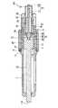
図1に第1実施形態を示す。第1実施形態の測定器は、円筒形状の本体1と、この本体1の内部に設けられたスピンドル11と、本体1の外部に設けられたシンブル21と、本体1の内部にスピンドル11の移動方向と同方向へ移動可能かつ任意の位置で固定可能に設けられたスリーブ31と、このスリーブ31とスピンドル11とを連結する連結部材41と、付勢力可変部材51と、付勢手段としての加圧ばね61と、付勢力表示手段71と、図示省略の位置検出表示手段とを含んで構成されている。
【0024】
前記スピンドル11は、前記本体1の内部に軸方向へ移動可能に設けられているとともに、先端部11Aが本体1から突出されている。スピンドル11の基端部11Bには、前記本体1の内周面に突設されたキーピン2に摺動自在に嵌合するキー溝12が軸方向に沿って形成されている。これにより、スピンドル11は、軸方向へは移動可能であるが、回転が規制された状態(回転不能状態)で本体1に保持されている。なお、キーピン2とキー溝12との関係は、逆に設けても同様な効果が得られる。
【0025】
前記シンブル21は、前記本体1の外径より大きい径の円筒形状に形成され、一端側が本体1の外周定位置において回転可能に保持されている。つまり、本体1およびシンブル21の対応する円周方向に沿って形成されたキー溝3,22およびこれに嵌合するキーリング4によって、本体1の外周定位置において回転可能に設けられている。なお、キー溝を本体1およびシンブル21の一方にのみ設け、他方にキーピンあるいはキーねじを設けてもよい。また、シンブル21の内周面には、雌ねじ23が形成されている。
【0026】
前記スリーブ31は、片側端部で連結された内外2重筒構造に形成されている。内筒部分32は、前記本体1の内部に軸方向移動可能に収納されているとともに、外筒部分33は、前記本体1とシンブル21との隙間に挿入され、かつ、外周面に前記シンブル21の雌ねじ23に螺合する雄ねじ34を有する。内筒部分32の内周面には前記付勢力可変部材51が螺合される雌ねじ35が形成されているとともに、外周面には前記本体1の内周面に突設されたキーピン5に摺動自在に嵌合するキー溝36が軸方向に沿って形成されている。これにより、スリーブ31は、軸方向へは移動可能であるが、回転が規制された状態(回転不能状態)で本体1に保持されている。なお、キーピン5とキー溝36との関係は、逆に設けても同様な効果が得られる。
【0027】
前記連結部材41は、前記スリーブ31と前記スピンドル11とを連結するとともに、これらの移動方向に所定ストロークで両者の相対移動を許容するように構成されている。つまり、前記スピンドル11の基端面に螺合されるねじ部42と、前記スリーブ31の内端開口鍔部内面側に当接するフランジ部43と、これらを連結する中間部44とを備える。これにより、スリーブ31とスピンドル11とは、これらの移動方向に所定ストロークで相対移動できるように構成されている。
【0028】
前記加圧ばね61は、コイルばねによって構成されているとともに、前記付勢力可変部材51と前記連結部材41との間に収納され、連結部材41を介して前記スピンドル11を被測定物に当接する方向へ付勢している。
前記付勢力表示手段71は、前記連結部材41に前記付勢力可変部材51の中心孔を貫通して突設された目盛棹72と、この目盛棹72の長手方向に沿って一定間隔おきに形成された目盛72Aとを含んで構成されている。ここで、目盛棹72および目盛72Aからなる付勢力表示手段71は、付勢力可変部材51の螺合によって可変された付勢手段としての加圧ばね61の予圧力を表示する予圧力表示手段201も兼ねている。
【0029】
次に、測定方法を説明する。
測定にあたって、本体1を保持して、シンブル21を回転させると、スリーブ31、加圧ばね61、連結部材41およびスピンドル11が一体となって、これらの軸方向(ここでは、図1中左方向)へ移動される。スピンドル11の先端部11Aが被測定物に当接したのち、さらに、シンブル21を回転し続けると、スピンドル11はこれ以上移動することができないので、加圧ばね61が圧縮されていく。このとき、加圧ばね61がスピンドル11を付勢する力、つまり、測定力は、圧縮量に比例して増加した力を予圧力に加えたものである。従って、加圧ばね61の圧縮量が一定の位置では測定力は一定である。なお、予圧力は、付勢力可変部材51を回転させてスリーブ31に対する位置を変えることにより、変えることができ、かつ、予圧力表示手段201によって確認できる。
【0030】
加圧ばね61の圧縮量は、連結部材41と付勢力可変部材51との間の相対的なずれ量と同じで、付勢力表示手段71の目盛棹72が付勢力可変部材51から突出した突出量で読み取ることができる。つまり、付勢力可変部材51の端面に一致する目盛棹72の目盛72Aを読み取ることにより、測定力を知ることができる。従って、付勢力可変部材51の端面に一致する目盛棹72の目盛72Aが予め設定した値になったときに、シンブル21の回転を止め、このときのスピンドル11の移動位置を図示省略の位置検出表示手段によって読み取れば、所望測定力下で測定を行うことができる。
【0031】
従って、第1実施形態によれば、加圧ばね61の圧縮量、つまり、測定力を付勢力表示手段71に表示するようにしたので、その付勢力表示手段71に表示された測定力を確認しながら、被測定物の材質や形状に応じた最適な測定力で測定することできる。つまり、被測定物の材質が軟質の場合には、微測定力で測定することができ、また、多数の被測定物を常に一定の測定力で測定することもできる。
【0032】
また、内部に加圧ばね61を収納したスリーブ31に付勢力可変部材51を螺合したので、この付勢力可変部材51を回転させることにより、付勢力可変部材51から連結部材41までの距離を変化させることができる。従って、その間に収納された加圧ばね61の圧縮量を変化させることができる。つまり、簡単な構成により、予圧力を変化させることができる。しかも、その予圧力を予圧力表示手段201によって確認できる。
【0033】
とくに、付勢力表示手段71は、連結部材41に付勢力可変部材51を貫通して突設された目盛棹72と、この目盛棹72の長手方向に沿って一定間隔おきに形成された目盛72Aとを含んで構成したので、スリーブ31に対する付勢力可変部材51の螺合位置を変えることによって予圧力を変化させていくと、あるいは、測定時にスピンドル11が被測定物に当接したのち、スリーブ31をさらに同方向へ移動させていくと、目盛棹72が付勢力可変部材51から突出する量も変化していくから、その目盛棹72に形成された目盛72Aを読み取ることにより、加圧ばね61の圧縮量、つまり、測定力を読み取ることができる。従って、目盛72Aを見ながら予圧力を調整でき、あるいは、所望の測定力で測定を行うことができる。
【0034】
また、本体1の定位置にシンブル21を回転可能に設け、このシンブル21にスリーブ31を螺合したので、シンブル21の回転により、スリーブ31を所定量ずつ微細に移動させることができるとともに、任意の位置で停止させることができる。従って、測定力を微調整しながら測定を行うことができるから、高精度な測定が期待できる。
【0035】
[第2実施形態]
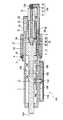
図2に第2実施形態を示す。第2実施形態の測定器は、第1実施形態の測定器とは、付勢力表示手段の構成が異なり、また、スピンドル11の移動位置を指針の回転角として検出する位置検出表示手段101が付加されている。
本実施形態の付勢力表示手段71Aは、前記連結部材41に前記付勢力可変部材51を貫通して突設され外端部に雄ねじ73Aを有するねじ軸73と、このねじ軸73に螺合されかつ前記スリーブ31に設けられたアーム74に回転可能かつ軸方向へ移動不能に設けられたナット部材75と、このナット部材75に固定された指針76とを含んで構成されている。
【0036】
本実施形態の位置検出表示手段101は、前記スピンドル11の軸方向に沿って形成されたラック102と、このラック102に噛合しかつ本体1に軸103を介して回転可能に支持されたピニオン104と、このピニオン104の軸103に固定された歯車105と、この歯車105に噛合された歯車106と、この歯車106を有し本体1に回転可能に支持された指針軸107と、この指針軸107に取り付けられた指針108と、この指針108の回転角を表示する目盛盤109と、この目盛盤109および指針108を覆う透明ケース110とから構成されている。
【0037】
従って、第2実施形態によれば、測定時にスピンドル11が被測定物に当接したのち、シンブル21を回転し続けて、スリーブ31をさらに同方向へ移動させると、連結部材41とスリーブ31とが相対変位される。すると、ねじ軸73とナット部材75も相対変位するから、ナット部材75が回転され、これにより、指針76が回転される。従って、連結部材41とスリーブ31との相対変位を指針76の回転角によって読み取ることができるから、その回転角が所望の角度に達したときに、位置検出表示手段101の指針108と目盛盤109とからスピンドル11の位置を読み取れば、所望の測定力下で測定を行うことができる。
なお、前記実施形態において、位置検出表示手段については、スピンドル11の移動位置を電気的信号として検出し、それをデジタル表示する位置検出表示手段であってもよい。また、アーム74には、指針76の回転角を表す角度目盛を付した目盛盤を設けておけば、指針76の回転角を正確に読み取ることができる。
【0038】
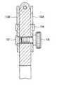
[第3実施形態]
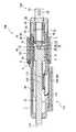
図3に第3実施形態を示す。第3実施形態の測定器は、第1実施形態の測定器とは、付勢力表示手段の構成が異なり、また、スピンドル11の移動位置を電気的信号として検出、表示する位置検出表示手段111が付加されている。
本実施形態の位置検出表示手段111は、前記スピンドル11に設けられたスケール112と、このスケール112に所定のギャップを隔てて前記本体1側に対向配置された検出スケール113と、この両スケール112,113の相対変位量を電気的信号として検出する検出回路114と、この検出回路114で検出された相対変位量をデジタル表示するデジタル表示部115とから構成されている。
【0039】
本実施形態の付勢力表示手段71Bは、前記スピンドル11とスリーブ31とが所定距離だけ接近したことを検知する検知スイッチ81と、この検知スイッチ81が作動したことを表示する表示部86(デジタル表示部115の一部に構成されている)とを含んで構成されている。
検知スイッチ81は、スピンドル11とスリーブ31とのいずれか一方(ここではスピンドル11)に絶縁部材82を介して設けられた電極板ばね83と、この電極板ばね83に対応していずれか他方(ここではスリーブ31)に設けられた電極84とから構成されている。検知スイッチ81からの信号は、電線85を介して前記検出回路114に入力され、表示部86に測定力が一定値に達したことが表示され、かつ、デジタル表示部115の表示値が自動的にホールドされるように構成されている。
【0040】
従って、第3実施形態によれば、測定時にスピンドル11が被測定物に当接したのち、シンブル21を回転し続けて、スリーブ31をさらに同方向へ移動させていくと、スピンドル11とスリーブ31とが相対変位される。すると、加圧ばね61の圧縮量が変化していく。このとき、スピンドル11とスリーブ31とが所定距離だけ接近すると、検知スイッチ81が作動され、そのことが表示部86に表示される。従って、加圧ばね61の圧縮量が一定量に達したこと、つまり、一定の測定力に達したことを表示部86の表示によって読み取ることができるから、定測定力で測定を行うことができる。しかも、加圧ばね61の圧縮量が一定量に達したとき、デジタル表示部115の表示値が自動的にホールドされるから、スリーブ31の送り過ぎに注意を払わなくてもよく、使い勝手に優れている。
【0041】
なお、本実施形態においては、付勢力可変部材51の外周面軸方向に目盛52が付設され、これにより、加圧ばね61による予圧力を確認できるようになっている。つまり、付勢力可変部材51の外周軸方向に沿って設けられた目盛52によって、予圧力表示手段202が構成されている。従って、付勢力可変部材51の外周軸方向に沿って目盛52を設けるだけの比較的簡単な構成で、予圧力表示手段202を構成できる。
【0042】
[第4実施形態]
図4に第4実施形態を示す。第4実施形態の測定器は、第3実施形態の測定器とは、付勢力表示手段の構成が異なる。
本実施形態の付勢力表示手段71Cは、前記連結部材41と加圧ばね61との間に設けられた力検出器91と、この力検出器91に電線85を介して接続され力検出器91で検出された力の大きさを表示する表示部92とを含んで構成されている。ここで、力検出器91としては、圧電素子やロードセルなどが用いられている。表示部92は、前記デジタル表示部115の一部に形成され、力の量をバーグラフとして表示するものであるが、これに限らず、数値として表示するものでもよい。
【0043】
従って、第4実施形態によれば、加圧ばね61の圧縮量に伴う力を力検出器91によって直接検出し、それを表示部92に表示するようにしたので、測定力を直接確認することができ、所望の測定力下での測定をより正確に行うことができる。
また、表示部92に表示する力の大きさをバーグラフとして表示すようにしたので、加圧ばね61を圧縮していく過程が視覚で確認できるので、スリーブ31を希望の位置で停止させやすい。
【0044】
[第5実施形態]
図5に第5実施形態を示す。第5実施形態の測定器は、第3実施形態の測定器において、本体1の一端側をL字状に延長し、この先端部内端面にスピンドル11との間に被測定物を挟持するアンビル121を取り付けた構成、つまり、マイクロメータ120として構成した例である。
従って、第5実施形態によれば、スピンドル11とアンビル121との間に被測定物を挟持したのち、さらに、シンブル21を回転させて、付勢力表示手段71Cの表示部86が予め設定した値を表示したときに、シンブル21の回転を停止して、デジタル表示部115の表示値を読み取ることにより、所望の測定力下で被測定物の寸法を測定することができる。
なお、本実施形態のようにマイクロメータとする構成は、第3実施形態の測定器に限らず、第1実施形態、第2実施形態、第4実施形態の測定器でも、同様に応用することができる。
【0045】
[第6実施形態]
図6に第6実施形態を示す。第6実施形態の測定器は、第5実施形態のマイクロメータ120に、被測定物をアンビル121に保持する保持手段131を付設した例である。
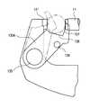
保持手段131は、詳細を図7〜図9に示すように、本体1のアンビル121近傍部分に貫通して設けられた支持軸132と、この支持軸132の両端側に本体1を挟んで取り付けられた一対のクランプ片133A,133Bと、この一対のクランプ片133A,133Bの略中間部を連結する連結ピン134と、前記支持軸132に螺合され一対のクランプ片133A,133Bを任意の回転位置で締め付けて固定するクランプねじ135とから構成されている。
クランプ片133A,133Bの先端部は、被測定物を挟んだ状態において、被測定物の下面を支持する支持面136と、この支持面136に対して略直交しアンビル121との間に被測定物を挟持する挟持面137とを有する形状に切欠形成されている。具体的には、図7に示すように、被測定物の径が異なっても、スピンドル11とアンビル121とを結ぶ軸線に対して、被測定物の中心軸が交差しかつ直交するように、支持面136と挟持面137との形状が決められている。
【0046】
従って、第6実施形態によれば、被測定物をアンビル121とクランプ片133A,133Bの先端部とで保持し、被測定物の中心軸がスピンドル11とアンビル121とを結ぶ軸線と交差しかつ直交した姿勢に保持した状態で測定することができる。そのため、たとえば、細い線材のように剛性が小さく撓んだり、あるいは、円筒形のようなピンなどのように転がりやすい形状の被測定物であっても、被測定物をアンビル121とクランプ片133A,133Bの先端部とで安定して保持することができるから、測定操作を容易にかつ正確に行うことができる。
【0047】
[第7実施形態]
図10に第7実施形態を示す。第7実施形態の測定器は、第3実施形態の測定器と、この測定器を保持するスタンド141とを備えた測定装置の例である。
スタンド141は、測定台142を有するベース143と、このベース143に立設された支柱144と、この支柱144に昇降可能かつ固定可能に設けられた昇降アーム145と、この昇降アーム145の先端に設けられ前記測定器の本体1の部分を挟持するクランプ機構146とを備えている。
【0048】
従って、第7実施形態によれば、スタンド141に測定器を保持したのち、測定台142上に被測定物を載置する。ここで、シンブル21を回転させて、スピンドル11を下方へ移動させ被測定物に当接させる。さらに、シンブル21を回転させ、付勢力表示手段の表示部86が予め設定した値を表示したときに、シンブル21の回転を停止する。ここで、デジタル表示部115の表示値を読み取ることにより、所望の測定力下で被測定物の寸法を測定することができる。
なお、本実施形態のようにスタンド141に支持する構成は、第3実施形態の測定器に限らず、第1実施形態、第2実施形態、第4実施形態の測定器でも、同様に応用することができる。
【0049】
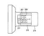
[第8実施形態]
図11および図12に第8実施形態を示す。第8実施形態の測定器は、第3実施形態の測定器(図3に示す測定器)とは、予圧力表示手段が異なり、また、付勢力可変部材51を覆うカバーが本体に着脱可能に設けられている点が異なる。本実施形態の予圧力表示手段203は、付勢力可変部材51の外周に回転調整可能かつ軸方向へ位置調整可能に設けられた表示筒204を備える。つまり、表示筒204には止めねじ205が螺合され、その止めねじ205が付勢力可変部材51の途中に形成された環状溝206内に突出、当接されている。これにより、止めねじ205の位置を変えることにより、表示筒204が付勢力可変部材51の外周に回転調整可能かつ軸方向へ位置調整可能になっている。
表示筒204の外周には、その軸方向に沿って目盛207および測定力を表す数値208が設けられている。
【0050】
本実施形態のカバー211は、本体1の後端部に螺合されたシンブル固定部材212と、このシンブル固定部材212に回動可能かつ止めねじ213によって固定可能に設けられた筒状のカバー部材214とから構成されている。カバー部材214には、目盛207や数値208を露出するための窓215と、止めねじ205を調整するための孔216とがそれぞれ設けられている。窓215の近傍には、調整目標表示マーク217が設けられている。
【0051】
なお、本実施形態の測定器は、スリーブ31を軸方向へ移動させる駆動機構が異なる。本実施形態では、本体1の軸方向にキー溝221が形成され、このキー溝221に摺動するキーピン222,223がスリーブ31および連結部材41に突設されている。また、本実施形態のシンブル21は、本体1の外周に回転可能に設けられた内筒224と、この内筒224の外周にコイルばね225を介して回転可能に設けられた外筒226とから構成されている。内筒224の内周面には、螺旋溝227が形成され、この螺旋溝227に前記キーピン222が摺動可能に係合されている。これにより、外筒226を回転させると、その回転がコイルばね225を介して内筒224に伝達される結果、キーピン222およびキー溝221の作用によって、スリーブ31が軸方向へ移動されるようになっている。
【0052】
また、本実施形態では、検知スイッチ81を構成する電極板ばね83がスリーブ31に設けられた絶縁駒228に接しているが、測定力が所定値に達したとき、つまり、加圧ばね61が所定量圧縮されたときに絶縁駒228から外れ、導電性部材からなるスリーブ31に接して、ホールド指令が出力されるように構成されている。
また、付勢力可変部材51の内部には、加圧ばね61の端部を受けるばね受け部材229が設けられている。このばね受け部材229は、加圧ばね61を受ける鍔部と、付勢力可変部材51の内底面に球面で接する球面部とを有する。
【0053】
従って、第8実施形態によれば、目盛207を有する表示筒204を、付勢力可変部材51の外周に対して回転調整、あるいは、軸方向へ位置調整することにより、基準となる位置に表示筒204の基準目盛207を一致させることができる。従って、加圧ばね61の製作上のばらつきなどがあっても、特別な加工や新たな部材を追加することなく、基準となる位置に表示筒204の基準目盛207を一致させることができる。
【0054】
また、付勢力可変部材51がカバー211で覆われているから、測定中に付勢力可変部材51に接触して付勢力可変部材51の螺合位置が変動するのを防止できる。よって、測定力のばらつきも未然に防止できる。しかも、カバー211には、目盛207を露出するための窓215が設けられているから、その窓215を通して、目盛207を視認できる。つまり、測定中に付勢力可変部材51に接触して付勢力可変部材51の螺合位置が変動するのを防止しつつ、目盛207を視認できる。
【0055】
また、付勢力可変部材51の内部には、加圧ばね61の端部を受けるばね受け部材229が設けられているから、付勢力可変部材51の内底面に球面で接する球面部により、加圧ばね61の調整時にその加圧ばね61が回転方向にねじれながら伸縮するのを防止でき、直線的な伸縮を可能にできる。
【0061】
なお、前記各実施形態では、スリーブ31をシンブル21の回転によって軸方向へ移動させるようにしたが、手動で行ってもよく、あるいは、レリーズによる駆動、レバーによる駆動、ラックとピニオンによる駆動、モータによる駆動などいずれでもよい。
また、前記各実施形態では、連結部材41の一端側をスピンドル11に固定し、他端側をスリーブ31に対して所定ストロークで移動可能に連結したが、連結部材41の両端側をスピンドル11とスリーブ31とにそれぞれ所定ストロークで移動可能に連結してもよい。
【0062】
【発明の効果】
本発明の測定器によれば、被測定物の材質や形状に応じて最適な測定力で測定することができる。
【図面の簡単な説明】
【図1】 本発明の第1実施形態を示す断面図である。
【図2】 本発明の第2実施形態を示す断面図である。
【図3】 本発明の第3実施形態を示す断面図である。
【図4】 本発明の第4実施形態を示す断面図である。
【図5】 本発明の第5実施形態を示す正面図である。
【図6】 本発明の第6実施形態を示す正面図である。
【図7】 同上実施形態の要部を示す拡大正面図である。
【図8】 同上実施形態の要部を示す拡大平面図である。
【図9】 同上実施形態の要部を示す拡大断面図である。
【図10】 本発明の第7実施形態を示す正面図である。
【図11】 本発明の第8実施形態を示す断面図である。
【図12】 同上実施形態の予圧表示手段を示す正面図である。
【符号の説明】
1 本体
11 スピンドル
21 シンブル
31 スリーブ
41 連結部材
51 付勢力可変部材
52 目盛
61 加圧ばね(付勢手段)
71、71A〜71C 付勢力表示手段
72 目盛棹
72A 目盛
73 ねじ軸
73A 雄ねじ
74 アーム
75 ナット部材
76 指針
81 検知スイッチ
86 表示部
91 力検出器
92 表示部
120 マイクロメータ
121 アンビル
131 保持手段
201,202,203 予圧力表示手段
204 表示筒
207 目盛
215 カバー[0001]
BACKGROUND OF THE INVENTION
The present invention relates to a measuring instrument for measuring a dimension of an object to be measured from a moving position of the spindle when the spindle is brought into contact with the object to be measured. Specifically, it has a main body and a spindle provided on the main body so as to be movable in the axial direction. The spindle is brought into contact with an object to be measured while moving in the axial direction, and the measured position is measured from the moving position of the spindle at that time. The present invention relates to a measuring instrument that measures the dimensions of an object, and displays the measuring force.
[0002]
[Background]
In a measuring instrument (for example, a micrometer) that measures the dimension of the object to be measured by contacting the object to be measured with a spindle that is movably provided on the main body, and detecting the amount of displacement of the spindle. In addition to the thimble that advances and retracts in the direction, a ratchet mechanism is provided for bringing the spindle into contact with the object to be measured with a constant force.
In the measurement, after the object to be measured is positioned between the anvil and the spindle, the thimble is turned to move the spindle in a direction approaching the object to be measured, and the object to be measured is sandwiched between the anvil and the spindle. After that, when the hand of the thimble is released and the knob of the ratchet mechanism is turned, the ratchet mechanism rotates idly when a force exceeding a certain level acts on the spindle, so that the measurement can be performed with a constant measuring force.
[0003]
[Problems to be solved by the invention]
By the way, in the case of a measuring instrument that measures the dimensions of the object to be measured by bringing the spindle into contact with the object to be measured, the contact force when the spindle contacts the object to be measured, that is, the measuring force is important for the measurement result. Therefore, it is ideal to measure with the optimum measuring force according to the material and shape of the object to be measured.
However, in the conventional measuring instrument, as described above, although measurement can be performed with a constant measurement force, it is practically difficult to change the measurement force according to the material and shape of the object to be measured. there were.
[0004]
The objective of this invention is providing the measuring device which can be measured with the optimal measuring force according to the material and shape of a to-be-measured object.
[0005]
[Means for Solving the Problems]
The measuring instrument of the present invention employs the following configuration in order to achieve the above object.
The invention according to
[0006]
According to this measuring instrument, when the sleeve is moved in the axial direction of the spindle in measurement, the sleeve, the urging means, the connecting member, and the spindle are integrally moved in the same direction. After the tip of the spindle comes into contact with the object to be measured, if the sleeve is further moved in the same direction, the spindle cannot be moved any further, so that the urging means is compressed. At this time, the force by which the urging means urges the spindle, that is, the measurement force is obtained by adding the force increased in proportion to the compression amount to the preload, and the measurement force is displayed on the urging force display means. The
Therefore, it is possible to perform measurement with an optimum measuring force according to the material and shape of the object to be measured while confirming the measuring force displayed on the biasing force display means. That is, when the material of the object to be measured is soft, it can be measured with a fine measuring force, and a large number of objects to be measured can always be measured with a constant measuring force.
[0007]
In the above, the sleeve may be moved manually, or may be driven by a release, driven by a lever, driven by a rack and pinion, or driven by a motor. Are preferred).
As for the connecting member, one end side may be fixed to one of the spindle and the sleeve, and the other end side may be connected to either the other with a predetermined stroke, or both ends may be connected to the spindle and the sleeve. And movably connected with a predetermined stroke.
Any biasing means may be used as long as the spindle can be biased in the direction in which the spindle comes into contact with the object to be measured, but a coiled pressure spring or the like is preferable.
[0008]
According to a second aspect of the present invention, in the measuring instrument according to the first aspect, the urging force variable member that varies the urging force of the urging means is screwed into the sleeve. It is a vessel.
According to this measuring device, when the screwing position of the biasing force variable member screwed to the sleeve is changed, the distance from the biasing force variable member to the connecting member changes, so the amount of compression of the biasing means accommodated therebetween Is changed. That is, the preload can be changed. Therefore, the preload can be changed with a simple configuration.
[0009]
According to a third aspect of the present invention, in the measuring instrument according to the second aspect, the biasing force display means includes a scale rod provided through the coupling member through the biasing force variable member, and the scale rod. It is a measuring instrument characterized by including the scale formed at regular intervals along the longitudinal direction.
According to this measuring instrument, when the preload is changed by changing the screwing position of the biasing force variable member with respect to the sleeve, or after the spindle abuts the object to be measured during measurement, the sleeve is further moved in the same direction. The distance from the connecting member to the urging force variable member (that is, the amount of compression of the urging means) changes. Then, since the amount by which the scale bar protrudes from the biasing force variable member also changes, the amount of compression of the biasing means, that is, the measuring force can be read by reading the scale formed on the scale bar. Accordingly, the preload can be adjusted while looking at the scale, or the measurement can be performed with a desired measuring force.
[0010]
According to a fourth aspect of the present invention, in the measuring instrument according to the second aspect, the biasing force display means includes a screw shaft that is provided through the biasing force variable member in the connecting member and has a male screw outside. A measuring instrument comprising: a nut member that is screwed onto the screw shaft and that is rotatable on the sleeve and is not movable in the axial direction; and a pointer fixed to the nut member. It is.
According to this measuring instrument, when the sleeve further moves in the same direction after the spindle contacts the object to be measured at the time of measurement, the connecting member and the sleeve (or the biasing force variable member) are relatively displaced. . Then, the amount of compression of the urging means changes and the screw shaft and the nut member are also relatively displaced, so that the nut member is rotated, that is, the pointer is rotated. Therefore, since the compression amount of the urging means, that is, the measurement force can be read from the rotation angle of the pointer, the measurement can be performed with a desired measurement force while observing the rotation angle of the pointer.
In the above, if a scale plate with an angle scale indicating the rotation angle of the pointer is attached to the sleeve side, the rotation angle of the pointer can be accurately read.
[0011]
According to a fifth aspect of the present invention, in the measuring instrument according to the first or second aspect, the urging force display means includes a detection switch that detects that the spindle and the sleeve have approached a predetermined distance, It is a measuring instrument characterized by including the display part which displays that the detection switch act | operated.
According to this measuring instrument, when the sleeve further moves in the same direction after the spindle comes into contact with the object to be measured at the time of measurement, the spindle and the sleeve are relatively displaced. Then, the compression amount of the urging means changes. At this time, when the spindle and the sleeve come close to each other by a predetermined distance, the detection switch is activated and this is displayed on the display unit. Therefore, since it can be read by the display on the display section that the compression amount of the urging means has reached a certain amount, that is, a certain measurement force has been reached, measurement can always be performed with a constant measurement force. .
In the above, the detection switch can be composed of an electrode leaf spring provided on one of the spindle and the sleeve and an electrode provided on the other corresponding to the electrode leaf spring.
[0012]
According to a sixth aspect of the present invention, in the measuring instrument according to the fifth aspect, the position detection display means for detecting the moving position of the spindle as an electrical signal and digitally displaying the moving position of the spindle based on the detection result. The measuring instrument is provided and configured to hold the display value of the position detection display means when the detection switch is operated.
According to this measuring device, when the compression amount of the biasing means reaches a certain amount, the display value of the position detection display means is automatically held, so it is not necessary to pay attention to the excessive feeding of the sleeve, It is easy to use.
[0013]
The invention according to claim 7 is the measuring instrument according to
According to this measuring device, the force accompanying the compression amount of the urging means is directly detected by the force detector and displayed on the measuring force display section, so that the measuring force can be directly confirmed and desired. It is possible to perform the measurement with the measuring force more accurately.
In the above, the magnitude of the force displayed on the measurement force display unit may be displayed as a numerical value or may be displayed as a bar graph. If displayed as a bar graph, the process of compressing the biasing means can be visually confirmed, so that the sleeve can be easily stopped at a desired position.
[0014]
According to an eighth aspect of the present invention, in the measuring instrument according to any one of the first to seventh aspects, the sleeve is provided in the main body so as to be movable in the axial direction and non-rotatable. The measuring instrument is screwed into a thimble rotatably provided at a fixed position.
According to this measuring instrument, when the thimble is rotated, the sleeve screwed to the thimble is provided so as to be movable in the axial direction and non-rotatable with respect to the main body. Therefore, by rotating the thimble, the sleeve can be moved minutely by a predetermined amount and stopped at an arbitrary position.
[0015]
According to a ninth aspect of the present invention, in the measuring instrument according to any one of the first to eighth aspects, the main body has an anvil that faces the spindle and holds an object to be measured between the spindle. The anvil-side main body is provided with a holding means for holding an object to be measured between the anvil on both sides of the anvil sandwiching the axis of the spindle. It is a measuring instrument.
According to this measuring instrument, the object to be measured can be held by the anvil and the holding means, and in this state, the spindle can be brought into contact with the object to be measured for measurement. For this reason, for example, even if the object to be measured is bent with a small rigidity such as a thin wire rod, or a shape such as a cylindrical pin that is easy to roll, the object to be measured can be separated with an anvil and a holding means. Since it can hold stably, measurement operation can be performed easily and accurately.
[0016]
According to a tenth aspect of the present invention, in the measuring instrument according to the second aspect of the present invention, preload display means for displaying the preload of the biasing means that is varied by screwing of the biasing force variable member is provided. It is the measuring device characterized by this.
According to this measuring instrument, since the preload of the biasing means is displayed by the preload display means, the screwing position of the biasing force variable member can be adjusted while checking this display. Therefore, it is possible to accurately adjust the preload of the urging means.
[0017]
The invention described in
According to this measuring instrument, when the preload of the biasing means is varied while adjusting the screwing position of the biasing force variable member, the scale provided along the outer circumferential axis direction of the biasing force variable member with respect to the sleeve is adjusted. Since the position changes, the pre-pressure of the urging means can be read from the scale. Therefore, the pre-pressure display means can be configured with a relatively simple configuration in which a scale is provided along the outer peripheral axis direction of the biasing force variable member.
[0018]
A twelfth aspect of the present invention is the measuring instrument according to the eleventh aspect, wherein the pre-pressure display means is provided on the outer periphery of the biasing force variable member so as to be rotatable and axially adjustable. And a scale provided along the outer peripheral axis direction of the display cylinder.
According to this measuring instrument, the reference scale of the display cylinder is made to coincide with the reference position by rotating or adjusting the position of the display cylinder having the scale relative to the outer periphery of the biasing force variable member in the axial direction. be able to. Therefore, even if there is variation in manufacturing of the urging means, the reference scale of the display cylinder can be made to coincide with the reference position without adding special processing or new members.
[0019]
A thirteenth aspect of the present invention is the measuring instrument according to the eleventh or twelfth aspect, wherein a cover that covers the biasing force variable member is detachably provided on the main body. is there.
According to this measuring instrument, since the biasing force variable member is covered with the cover, it is possible to prevent the screwing position of the biasing force variable member from changing due to contact with the biasing force variable member during measurement. Therefore, variation in measuring force can be prevented beforehand.
[0020]
The invention described in claim 14 is the measuring instrument according to claim 13, wherein the cover is provided with a window for exposing the scale.
According to this measuring instrument, since the window for exposing the scale is provided on the cover, the scale can be visually recognized through the window. That is, the scale can be visually recognized while preventing the screwing position of the biasing force variable member from changing due to contact with the biasing force variable member during measurement.
[0023]
DETAILED DESCRIPTION OF THE INVENTION
Hereinafter, embodiments of the present invention will be described with reference to the drawings. In the following description, the same constituent elements are denoted by the same reference numerals, and the description thereof is omitted or simplified.
[First Embodiment]
FIG. 1 shows a first embodiment. The measuring instrument of the first embodiment includes a cylindrical
[0024]
The
[0025]
The
[0026]
The
[0027]
The connecting
[0028]
The pressurizing
The urging force display means 71 is formed on the connecting
[0029]
Next, a measurement method will be described.
In measurement, when the
[0030]
The compression amount of the
[0031]
Therefore, according to the first embodiment, since the compression amount of the
[0032]
Further, since the biasing force
[0033]
In particular, the urging force display means 71 includes a
[0034]
Further, since the
[0035]
[Second Embodiment]
FIG. 2 shows a second embodiment. The measuring instrument of the second embodiment is different from the measuring instrument of the first embodiment in the configuration of the urging force display means, and a position detection display means 101 for detecting the moving position of the
The biasing force display means 71A of the present embodiment is screwed into the
[0036]
The position detection display means 101 of this embodiment includes a
[0037]
Therefore, according to the second embodiment, when the
In the embodiment, the position detection display means may be position detection display means for detecting the moving position of the
[0038]
[Third Embodiment]
FIG. 3 shows a third embodiment. The measuring instrument of the third embodiment is different from the measuring instrument of the first embodiment in the configuration of the urging force display means, and a position detection display means 111 for detecting and displaying the moving position of the
The position detection /
[0039]
The urging force display means 71B of the present embodiment includes a
The
[0040]
Therefore, according to the third embodiment, when the
[0041]
In the present embodiment, a
[0042]
[Fourth Embodiment]
FIG. 4 shows a fourth embodiment. The measuring instrument of the fourth embodiment is different from the measuring instrument of the third embodiment in the configuration of the urging force display means.
The urging force display means 71 </ b> C of the present embodiment includes a
[0043]
Therefore, according to the fourth embodiment, the force accompanying the compression amount of the
Further, since the magnitude of the force displayed on the
[0044]
[Fifth Embodiment]
FIG. 5 shows a fifth embodiment. The measuring instrument of the fifth embodiment is the same as the measuring instrument of the third embodiment. The
Therefore, according to the fifth embodiment, after the object to be measured is sandwiched between the
Note that the configuration of the micrometer as in this embodiment is not limited to the measuring instrument of the third embodiment, and is similarly applied to the measuring instrument of the first embodiment, the second embodiment, and the fourth embodiment. Can do.
[0045]
[Sixth Embodiment]
FIG. 6 shows a sixth embodiment. The measuring instrument according to the sixth embodiment is an example in which holding means 131 for holding an object to be measured on the
As shown in detail in FIGS. 7 to 9, the holding means 131 is attached with a
The
[0046]
Therefore, according to the sixth embodiment, the object to be measured is held by the
[0047]
[Seventh Embodiment]
FIG. 10 shows a seventh embodiment. The measuring instrument according to the seventh embodiment is an example of a measuring apparatus including the measuring instrument according to the third embodiment and a
The
[0048]
Therefore, according to the seventh embodiment, after the measuring instrument is held on the
Note that the configuration supported by the
[0049]
[Eighth Embodiment]
11 and 12 show an eighth embodiment. The measuring instrument of the eighth embodiment is different from the measuring instrument of the third embodiment (the measuring instrument shown in FIG. 3) in the pre-pressure display means, and the cover that covers the biasing force
On the outer periphery of the
[0050]
The
[0051]
In addition, the measuring device of this embodiment differs in the drive mechanism which moves the
[0052]
In this embodiment, the
A
[0053]
Therefore, according to the eighth embodiment, the
[0054]
Further, since the biasing force
[0055]
In addition, since the
[0061]
In each of the above embodiments, the
In each of the above embodiments, one end side of the connecting
[0062]
【The invention's effect】
According to the measuring instrument of the present invention, it is possible to perform measurement with an optimum measuring force according to the material and shape of the object to be measured.
[Brief description of the drawings]
FIG. 1 is a cross-sectional view showing a first embodiment of the present invention.
FIG. 2 is a cross-sectional view showing a second embodiment of the present invention.
FIG. 3 is a cross-sectional view showing a third embodiment of the present invention.
FIG. 4 is a cross-sectional view showing a fourth embodiment of the present invention.
FIG. 5 is a front view showing a fifth embodiment of the present invention.
FIG. 6 is a front view showing a sixth embodiment of the present invention.
FIG. 7 is an enlarged front view showing the main part of the embodiment.
FIG. 8 is an enlarged plan view showing a main part of the embodiment.
FIG. 9 is an enlarged cross-sectional view showing a main part of the embodiment.
FIG. 10 is a front view showing a seventh embodiment of the present invention.
FIG. 11 is a sectional view showing an eighth embodiment of the present invention.
FIG. 12 is a front view showing preload display means of the embodiment.
[Explanation of symbols]
1 Body
11 Spindle
21 Thimble
31 sleeve
41 connecting member
51 Biasing force variable member
52 scale
61 Pressure spring (biasing means)
71, 71A-71C Energizing force display means
72 scale
72A scale
73 Screw shaft
73A Male thread
74 arms
75 Nut member
76 Guidelines
81 Detection switch
86 Display
91 Force detector
92 Display
120 micrometers
121 Anvil
131 Holding means
201, 202, 203 Pre-pressure display means
204 display tube
207 scale
215 cover
Claims (14)
Translated fromJapanese前記本体に前記スピンドルの移動方向と同方向へ移動可能かつ任意の位置で固定可能に設けられたスリーブと、
このスリーブと前記スピンドルとを連結するとともに、これらの移動方向に所定ストロークで両者の相対移動を許容する連結部材と、
前記スリーブ内に収納され前記連結部材を介して前記スピンドルを被測定物に当接する方向へ付勢する付勢手段と、
この付勢手段の付勢力を表示する付勢力表示手段とを備えたことを特徴とする測定器。The main body and a spindle provided on the main body so as to be movable in the axial direction are brought into contact with the object to be measured while moving the spindle in the axial direction, and the dimension of the object to be measured is determined from the moving position of the spindle at that time. In a measuring instrument that measures
A sleeve provided on the main body so as to be movable in the same direction as the spindle and fixed at an arbitrary position;
A coupling member that couples the sleeve and the spindle, and allows relative movement of the sleeve and the spindle with a predetermined stroke in the movement direction;
A biasing means that is housed in the sleeve and biases the spindle in a direction of contacting the object to be measured via the connecting member;
A measuring instrument comprising an urging force display means for displaying the urging force of the urging means.
前記スリーブには、前記付勢手段の付勢力を可変する付勢力可変部材が螺合されていることを特徴とする測定器。The measuring instrument according to claim 1, wherein
An urging force variable member that varies the urging force of the urging means is screwed onto the sleeve.
前記付勢力表示手段は、前記連結部材に前記付勢力可変部材を貫通して設けられた目盛棹と、この目盛棹の長手方向に沿って一定間隔おきに形成された目盛とを含んで構成されていることを特徴とする測定器。The measuring instrument according to claim 2,
The biasing force display means includes a scale rod provided through the connecting member through the biasing force variable member, and a scale formed at regular intervals along the longitudinal direction of the scale rod. A measuring instrument characterized by
前記付勢力表示手段は、前記連結部材に前記付勢力可変部材を貫通して設けられ外部に雄ねじを有するねじ軸と、このねじ軸に螺合されかつ前記スリーブに回転可能かつ軸方向へ移動不能に設けられたナット部材と、このナット部材に固定された指針とを含んで構成されていることを特徴とする測定器。The measuring instrument according to claim 2,
The biasing force display means is provided in the connecting member so as to penetrate the biasing force variable member and has a male screw on the outside, and is screwed into the screw shaft and is rotatable on the sleeve and not movable in the axial direction. A measuring instrument comprising: a nut member provided on the nut member; and a pointer fixed to the nut member.
前記付勢力表示手段は、前記スピンドルとスリーブとが所定距離だけ接近したことを検知する検知スイッチと、この検知スイッチが作動したことを表示する表示部とを含んで構成されていることを特徴とする測定器。The measuring instrument according to claim 1 or 2,
The urging force display means includes a detection switch that detects that the spindle and the sleeve are close to each other by a predetermined distance, and a display unit that displays that the detection switch is activated. Measuring instrument.
前記スピンドルの移動位置を電気的信号として検出し、その検出結果に基づくスピンドルの移動位置をデジタル表示する位置検出表示手段が設けられ、
この位置検出表示手段の表示値が前記検知スイッチが作動したときにホールドされるように構成されていることを特徴とする測定器。The measuring instrument according to claim 5, wherein
Position detection display means for detecting the movement position of the spindle as an electrical signal and digitally displaying the movement position of the spindle based on the detection result is provided,
A measuring instrument characterized in that the display value of the position detection display means is held when the detection switch is actuated.
前記付勢力表示手段は、前記連結部材と付勢手段との間に設けられた力検出器と、この力検出器で検出された力の大きさを表示する測定力表示部とを含んで構成されていることを特徴とする測定器。The measuring instrument according to claim 1 or 2,
The urging force display means includes a force detector provided between the connecting member and the urging means, and a measurement force display unit for displaying the magnitude of the force detected by the force detector. Measuring instrument characterized by being.
前記スリーブは、前記本体に軸方向へ移動可能かつ回転不能に設けられ、かつ、前記本体の定位置に回転可能に設けられたシンブルに螺合されていることを特徴とする測定器。The measuring instrument according to any one of claims 1 to 7,
The measuring device according to claim 1, wherein the sleeve is screwed into a thimble provided in the main body so as to be axially movable and non-rotatable, and rotatably provided at a fixed position of the main body.
前記本体には、前記スピンドルと対向しそのスピンドルとの間に被測定物を挟持するアンビルが設けられ、
このアンビル側の本体には、前記スピンドルの軸線を挟んだアンビルの両側において、前記アンビルとの間に被測定物を保持する保持手段が回動可能に設けられていることを特徴とする測定器。The measuring instrument according to any one of claims 1 to 8,
The main body is provided with an anvil that faces the spindle and holds an object to be measured between the spindle,
The anvil-side main body is provided with holding means for holding an object to be measured between the anvil on both sides of the anvil across the spindle axis so as to be rotatable. .
前記付勢力可変部材の螺合によって可変された前記付勢手段の予圧力を表示する予圧力表示手段が設けられていることを特徴とする測定器。The measuring instrument according to claim 2,
A measuring instrument, comprising: a pre-pressure display means for displaying a pre-pressure of the urging means varied by screwing of the urging force variable member.
前記予圧力表示手段は、前記付勢力可変部材の外周軸方向に沿って設けられた目盛を備えることを特徴とする測定器。The measuring instrument according to claim 10,
The measuring device according to claim 1, wherein the pre-pressure display means includes a scale provided along an outer peripheral axis direction of the biasing force variable member.
前記予圧力表示手段は、前記付勢力可変部材の外周に回転調整可能かつ軸方向へ位置調整可能に設けられた表示筒と、この表示筒の外周軸方向に沿って設けられた目盛とを備えることを特徴とする測定器。The measuring instrument according to claim 11, wherein
The pre-pressure display means includes a display cylinder provided on the outer periphery of the biasing force variable member so as to be rotatable and axially adjustable, and a scale provided along the outer peripheral axis direction of the display cylinder. A measuring instrument characterized by that.
前記付勢力可変部材を覆うカバーが前記本体に着脱可能に設けられていることを特徴とする測定器。The measuring instrument according to claim 11 or 12,
A measuring instrument, wherein a cover covering the biasing force variable member is detachably provided on the main body.
前記カバーには、前記目盛を露出するための窓が設けられていることを特徴とする測定器。The measuring instrument according to claim 13,
The measuring instrument, wherein the cover is provided with a window for exposing the scale.
Priority Applications (5)
| Application Number | Priority Date | Filing Date | Title |
|---|---|---|---|
| JP2001139923AJP3751540B2 (en) | 2000-07-26 | 2001-05-10 | Measuring instrument |
| US09/909,800US6553685B2 (en) | 2000-07-26 | 2001-07-23 | Measuring instruments |
| DE10136360ADE10136360B4 (en) | 2000-07-26 | 2001-07-26 | gauge |
| CN200410030443.1ACN1267694C (en) | 2000-07-26 | 2001-07-26 | Measuring instruments |
| CNB011243813ACN1194203C (en) | 2000-07-26 | 2001-07-26 | Measuring instrument |
Applications Claiming Priority (3)
| Application Number | Priority Date | Filing Date | Title |
|---|---|---|---|
| JP2000225316 | 2000-07-26 | ||
| JP2000-225316 | 2000-07-26 | ||
| JP2001139923AJP3751540B2 (en) | 2000-07-26 | 2001-05-10 | Measuring instrument |
Related Child Applications (1)
| Application Number | Title | Priority Date | Filing Date |
|---|---|---|---|
| JP2005321911ADivisionJP3913763B2 (en) | 2000-07-26 | 2005-11-07 | Measuring instrument |
Publications (2)
| Publication Number | Publication Date |
|---|---|
| JP2002107101A JP2002107101A (en) | 2002-04-10 |
| JP3751540B2true JP3751540B2 (en) | 2006-03-01 |
Family
ID=26596701
Family Applications (1)
| Application Number | Title | Priority Date | Filing Date |
|---|---|---|---|
| JP2001139923AExpired - Fee RelatedJP3751540B2 (en) | 2000-07-26 | 2001-05-10 | Measuring instrument |
Country Status (4)
| Country | Link |
|---|---|
| US (1) | US6553685B2 (en) |
| JP (1) | JP3751540B2 (en) |
| CN (2) | CN1267694C (en) |
| DE (1) | DE10136360B4 (en) |
Cited By (6)
| Publication number | Priority date | Publication date | Assignee | Title |
|---|---|---|---|---|
| DE102019205791A1 (en) | 2018-04-20 | 2019-10-24 | Mitutoyo Corporation | Method for controlling a small measuring device |
| DE102021111698A1 (en) | 2020-05-28 | 2021-12-02 | Mitutoyo Corporation | Automatic measuring device |
| DE102023120014A1 (en) | 2022-07-29 | 2024-02-01 | Mitutoyo Corporation | AUTOMATIC MEASURING DEVICE AND CONTROL METHOD OF THE SAME |
| DE102024103395A1 (en) | 2023-02-08 | 2024-08-08 | Mitutoyo Corporation | Automatic measuring device and control method therefor |
| DE102024124726A1 (en) | 2023-08-31 | 2025-03-06 | Mitutoyo Corporation | AUTOMATIC MEASURING DEVICE |
| DE102024124727A1 (en) | 2023-08-31 | 2025-03-06 | Mitutoyo Corporation | AUTOMATIC MEASURING DEVICE |
Families Citing this family (35)
| Publication number | Priority date | Publication date | Assignee | Title |
|---|---|---|---|---|
| US20030047009A1 (en)* | 2002-08-26 | 2003-03-13 | Webb Walter L. | Digital callipers |
| JP4520722B2 (en)* | 2002-12-10 | 2010-08-11 | 株式会社ミツトヨ | Rotary motion conversion mechanism and measuring machine |
| US6739068B1 (en)* | 2003-01-06 | 2004-05-25 | Pilling Weck Incorporated | Pliers with jaw spacing and load measuring readings |
| US7043852B2 (en)* | 2003-06-09 | 2006-05-16 | Mitutoyo Corporation | Measuring instrument |
| JP4806545B2 (en)* | 2005-08-10 | 2011-11-02 | 株式会社ミツトヨ | Measuring instrument |
| CN101236059A (en)* | 2007-02-02 | 2008-08-06 | 深圳富泰宏精密工业有限公司 | Measurement equipment and its measurement method |
| US20080229604A1 (en)* | 2007-03-19 | 2008-09-25 | Lin Wo | Digital thickness gauge for both exterior dimension and tube or hollow wall thickness |
| US20100088913A1 (en)* | 2008-10-15 | 2010-04-15 | Dustin Edward Conlon | Apparatus and Method for Simutaneously Functioning Internal Shaft and Plunger of a Micrometer |
| CN102141390B (en)* | 2010-12-16 | 2012-09-26 | 西安东风仪表厂 | Linear telescopic measurement device |
| JP2013088287A (en)* | 2011-10-18 | 2013-05-13 | Mitsutoyo Corp | Micrometer |
| DE102011087241A1 (en)* | 2011-11-28 | 2013-05-29 | Tyco Electronics Amp Gmbh | sensor module |
| US9032640B1 (en)* | 2011-12-15 | 2015-05-19 | Physical Optics Corporation | Self-normalizing panel thickness measurement system |
| US8739428B2 (en)* | 2012-07-03 | 2014-06-03 | Mitutoyo Corporation | Constant force spring actuator for a handheld micrometer |
| US9182210B2 (en)* | 2012-08-29 | 2015-11-10 | Ossur Hf | Caliper for measurement of an object |
| US20140063220A1 (en) | 2012-08-29 | 2014-03-06 | Ossur Hf | Method and Device for Ordering a Custom Orthopedic Device |
| JP6015313B2 (en)* | 2012-09-28 | 2016-10-26 | アイシン・エィ・ダブリュ株式会社 | Stroke measuring device |
| US9441937B2 (en) | 2012-10-19 | 2016-09-13 | General Electric Company | Method and apparatus for measuring thickness of an object |
| CN103267673B (en)* | 2013-06-17 | 2015-01-28 | 中国汽车技术研究中心 | Micro-displacement variation monitor and operation method thereof |
| CN104359378B (en)* | 2014-11-12 | 2017-06-23 | 西安交通大学 | A kind of digital vernier clearance ruler and its application method |
| DE102015207108A1 (en)* | 2015-04-20 | 2016-10-20 | Schaeffler Technologies AG & Co. KG | Measuring device for a machine tool and corresponding machine tool |
| CN105444695B (en)* | 2015-12-22 | 2019-03-22 | 四川大学 | The probe contact measuring head of dynamic characteristic is adjusted based on elastic element limit method |
| EP3225950B1 (en) | 2016-03-31 | 2018-09-12 | Tesa Sa | Portable displacement measuring instrument with constant force mechanism |
| CN106197217B (en)* | 2016-08-08 | 2019-03-12 | 洛阳轴承研究所有限公司 | A kind of accurate detection device of bearing ring outer-diameter accuracy |
| CN107462199A (en)* | 2017-08-08 | 2017-12-12 | 武汉理工光科股份有限公司 | A kind of scalable anti-offset lossless support displacement monitoring device |
| CN108050976B (en)* | 2017-11-21 | 2019-12-31 | 中国航发沈阳发动机研究所 | Detachable telescopic contact type measuring instrument |
| CN107863131B (en)* | 2017-12-01 | 2023-04-07 | 江汉大学 | Multifunctional size adjusting device |
| KR101937159B1 (en) | 2018-05-08 | 2019-01-11 | 주식회사 율촌 | Measurement jig for shaft |
| CN116929172A (en)* | 2018-06-12 | 2023-10-24 | 株式会社三丰 | Digital micrometer |
| CN109115066B (en)* | 2018-07-24 | 2020-12-18 | 嘉兴觅特电子商务有限公司 | Novel push type micrometer screw |
| CN112212763B (en)* | 2019-07-12 | 2025-10-03 | 明门(中国)幼童用品有限公司 | Thickness measuring device and thickness measuring method |
| CN110558681B (en)* | 2019-09-25 | 2024-04-05 | 安徽工程大学 | Remote shoe selecting system |
| CN112284200B (en)* | 2020-12-06 | 2024-09-24 | 李里 | Micrometer gauge |
| CN113375516B (en)* | 2021-07-18 | 2024-10-22 | 李里 | Digital display micrometer |
| CN113945138B (en)* | 2021-11-01 | 2025-05-02 | 安徽省广德中鼎汽车工具有限公司 | External surface curvature detection device for wheel maintenance and use method thereof |
| CN114812501B (en)* | 2022-06-21 | 2023-05-16 | 钱静 | Reading scale for level gauge detection |
Family Cites Families (19)
| Publication number | Priority date | Publication date | Assignee | Title |
|---|---|---|---|---|
| US570189A (en)* | 1896-10-27 | Micrometer-gage | ||
| US1188978A (en)* | 1915-07-21 | 1916-06-27 | Joseph H Mueller | Micrometer-calipers. |
| US1656927A (en)* | 1925-06-18 | 1928-01-24 | Ernest O Wheelock | Micrometer gauge |
| US2611967A (en)* | 1950-07-05 | 1952-09-30 | Marvin F Bennett | Micrometer |
| US2835040A (en)* | 1956-05-29 | 1958-05-20 | Elia Joseph J D | Micrometer gauge |
| JPS55147301A (en) | 1979-05-04 | 1980-11-17 | Japan Atom Energy Res Inst | Micrometer with short circuit |
| US4437241A (en)* | 1979-08-22 | 1984-03-20 | Lemelson Jerome H | Measuring instrument and method |
| JPS5920104U (en)* | 1982-07-27 | 1984-02-07 | 株式会社三豊製作所 | micrometer head |
| US4578868A (en)* | 1983-04-01 | 1986-04-01 | Mitutoyo Mfg. Co., Ltd. | Digital display measuring apparatus |
| JPH0212602U (en) | 1988-07-06 | 1990-01-26 | ||
| JPH04296601A (en) | 1991-03-27 | 1992-10-21 | Fujitsu Ltd | Micrometer |
| US5287631A (en)* | 1991-12-16 | 1994-02-22 | Ronald J. Stade | Precision extended-length micrometer with displacement meter probe adapter |
| FR2707757B1 (en) | 1993-07-15 | 1995-08-25 | Snecma | Tool for measuring a clamping force exerted by a movable rod of a length measuring device. |
| JP2965444B2 (en)* | 1993-10-01 | 1999-10-18 | 株式会社ミツトヨ | Constant pressure measuring machine |
| JP3115555B2 (en)* | 1998-04-03 | 2000-12-11 | 株式会社ミツトヨ | Micrometer |
| DE69818241T2 (en)* | 1998-07-16 | 2004-07-15 | Tesa Sa | Device for longitudinal measurements |
| JP2989589B1 (en) | 1998-09-14 | 1999-12-13 | スコービル・ジャパン株式会社 | Electronic dough thickness measuring instrument |
| JP3724995B2 (en)* | 1999-11-10 | 2005-12-07 | 株式会社ミツトヨ | Micrometer |
| US6505414B2 (en)* | 2000-06-19 | 2003-01-14 | Mitutoyo Corporation | Comparator |
- 2001
- 2001-05-10JPJP2001139923Apatent/JP3751540B2/ennot_activeExpired - Fee Related
- 2001-07-23USUS09/909,800patent/US6553685B2/ennot_activeExpired - Lifetime
- 2001-07-26CNCN200410030443.1Apatent/CN1267694C/ennot_activeExpired - Lifetime
- 2001-07-26CNCNB011243813Apatent/CN1194203C/ennot_activeExpired - Lifetime
- 2001-07-26DEDE10136360Apatent/DE10136360B4/ennot_activeExpired - Lifetime
Cited By (7)
| Publication number | Priority date | Publication date | Assignee | Title |
|---|---|---|---|---|
| DE102019205791A1 (en) | 2018-04-20 | 2019-10-24 | Mitutoyo Corporation | Method for controlling a small measuring device |
| US10996043B2 (en) | 2018-04-20 | 2021-05-04 | Mitutoyo Corporation | Method for controlling small-sized measurement device |
| DE102021111698A1 (en) | 2020-05-28 | 2021-12-02 | Mitutoyo Corporation | Automatic measuring device |
| DE102023120014A1 (en) | 2022-07-29 | 2024-02-01 | Mitutoyo Corporation | AUTOMATIC MEASURING DEVICE AND CONTROL METHOD OF THE SAME |
| DE102024103395A1 (en) | 2023-02-08 | 2024-08-08 | Mitutoyo Corporation | Automatic measuring device and control method therefor |
| DE102024124726A1 (en) | 2023-08-31 | 2025-03-06 | Mitutoyo Corporation | AUTOMATIC MEASURING DEVICE |
| DE102024124727A1 (en) | 2023-08-31 | 2025-03-06 | Mitutoyo Corporation | AUTOMATIC MEASURING DEVICE |
Also Published As
| Publication number | Publication date |
|---|---|
| CN1194203C (en) | 2005-03-23 |
| CN1267694C (en) | 2006-08-02 |
| US6553685B2 (en) | 2003-04-29 |
| CN1334436A (en) | 2002-02-06 |
| JP2002107101A (en) | 2002-04-10 |
| CN1525136A (en) | 2004-09-01 |
| DE10136360A1 (en) | 2002-02-28 |
| US20020017032A1 (en) | 2002-02-14 |
| DE10136360B4 (en) | 2010-03-18 |
Similar Documents
| Publication | Publication Date | Title |
|---|---|---|
| JP3751540B2 (en) | Measuring instrument | |
| US7533474B2 (en) | Caliper gauge | |
| JP2761357B2 (en) | Tool for measuring the clamping force applied by the movable spindle of a length measuring instrument | |
| JPH0159523B2 (en) | ||
| JP3406044B2 (en) | Dial gauge centering device | |
| JPH01227903A (en) | Dial cylinder gage | |
| JP3913763B2 (en) | Measuring instrument | |
| US4805310A (en) | Probe for the measurement of dimensions | |
| JP5222557B2 (en) | A micrometer configured with a non-rotating spindle | |
| JP4806545B2 (en) | Measuring instrument | |
| JP3531924B2 (en) | Surface texture measuring machine | |
| JP3220341B2 (en) | Dimension measuring device | |
| JPH0339611B2 (en) | ||
| JPS5820881Y2 (en) | Dimension measuring device | |
| JPH1047903A (en) | Length measurement machine | |
| JPS61219819A (en) | Digital display type measuring device | |
| US2580227A (en) | Gauge | |
| JPH0434681B2 (en) | ||
| TWI304470B (en) | ||
| JPS5919283B2 (en) | dimension measuring instrument | |
| JP2004163151A (en) | Inside micrometer device | |
| US20090223074A1 (en) | Gage for measuring disc brake thickness | |
| JPH0212566Y2 (en) | ||
| JP2008241527A (en) | Surface roughness measuring device | |
| JPS6025523Y2 (en) | Dimension measuring device |
Legal Events
| Date | Code | Title | Description |
|---|---|---|---|
| A621 | Written request for application examination | Free format text:JAPANESE INTERMEDIATE CODE: A621 Effective date:20040329 | |
| A977 | Report on retrieval | Free format text:JAPANESE INTERMEDIATE CODE: A971007 Effective date:20050824 | |
| A131 | Notification of reasons for refusal | Free format text:JAPANESE INTERMEDIATE CODE: A131 Effective date:20050906 | |
| A521 | Request for written amendment filed | Free format text:JAPANESE INTERMEDIATE CODE: A523 Effective date:20051107 | |
| TRDD | Decision of grant or rejection written | ||
| A01 | Written decision to grant a patent or to grant a registration (utility model) | Free format text:JAPANESE INTERMEDIATE CODE: A01 Effective date:20051129 | |
| A61 | First payment of annual fees (during grant procedure) | Free format text:JAPANESE INTERMEDIATE CODE: A61 Effective date:20051207 | |
| R150 | Certificate of patent or registration of utility model | Ref document number:3751540 Country of ref document:JP Free format text:JAPANESE INTERMEDIATE CODE: R150 Free format text:JAPANESE INTERMEDIATE CODE: R150 | |
| FPAY | Renewal fee payment (event date is renewal date of database) | Free format text:PAYMENT UNTIL: 20111216 Year of fee payment:6 | |
| R250 | Receipt of annual fees | Free format text:JAPANESE INTERMEDIATE CODE: R250 | |
| FPAY | Renewal fee payment (event date is renewal date of database) | Free format text:PAYMENT UNTIL: 20141216 Year of fee payment:9 | |
| R250 | Receipt of annual fees | Free format text:JAPANESE INTERMEDIATE CODE: R250 | |
| R250 | Receipt of annual fees | Free format text:JAPANESE INTERMEDIATE CODE: R250 | |
| R250 | Receipt of annual fees | Free format text:JAPANESE INTERMEDIATE CODE: R250 | |
| LAPS | Cancellation because of no payment of annual fees |