JP3751026B2 - Analysis cell - Google Patents
Analysis cellDownload PDFInfo
- Publication number
- JP3751026B2 JP3751026B2JP51305998AJP51305998AJP3751026B2JP 3751026 B2JP3751026 B2JP 3751026B2JP 51305998 AJP51305998 AJP 51305998AJP 51305998 AJP51305998 AJP 51305998AJP 3751026 B2JP3751026 B2JP 3751026B2
- Authority
- JP
- Japan
- Prior art keywords
- electrode
- electrodes
- cell
- cell according
- barrier
- Prior art date
- Legal status (The legal status is an assumption and is not a legal conclusion. Google has not performed a legal analysis and makes no representation as to the accuracy of the status listed.)
- Expired - Fee Related
Links
- 239000012528membraneSubstances0.000claimsdescription47
- 230000004888barrier functionEffects0.000claimsdescription41
- 238000009792diffusion processMethods0.000claimsdescription27
- 239000000126substanceSubstances0.000claimsdescription21
- 229910052709silverInorganic materials0.000claimsdescription16
- 239000004332silverSubstances0.000claimsdescription16
- BQCADISMDOOEFD-UHFFFAOYSA-NSilverChemical group[Ag]BQCADISMDOOEFD-UHFFFAOYSA-N0.000claimsdescription12
- 230000000694effectsEffects0.000claimsdescription11
- -1silver halideChemical class0.000claimsdescription10
- 238000004544sputter depositionMethods0.000claimsdescription8
- 230000000903blocking effectEffects0.000claimsdescription7
- 230000006835compressionEffects0.000claimsdescription7
- 238000007906compressionMethods0.000claimsdescription7
- 239000007788liquidSubstances0.000claimsdescription6
- 238000000034methodMethods0.000claimsdescription5
- 239000011248coating agentSubstances0.000claimsdescription4
- 238000000576coating methodMethods0.000claimsdescription4
- 238000004519manufacturing processMethods0.000claimsdescription3
- 238000005192partitionMethods0.000claimsdescription2
- 210000004027cellAnatomy0.000description60
- 239000000243solutionSubstances0.000description27
- 150000002500ionsChemical class0.000description20
- BASFCYQUMIYNBI-UHFFFAOYSA-NplatinumChemical compound[Pt]BASFCYQUMIYNBI-UHFFFAOYSA-N0.000description18
- 238000005259measurementMethods0.000description14
- 229910052751metalInorganic materials0.000description14
- 239000002184metalSubstances0.000description14
- QIGBRXMKCJKVMJ-UHFFFAOYSA-N1,4-BenzenediolNatural productsOC1=CC=C(O)C=C1QIGBRXMKCJKVMJ-UHFFFAOYSA-N0.000description12
- AZQWKYJCGOJGHM-UHFFFAOYSA-N1,4-benzoquinoneChemical compoundO=C1C=CC(=O)C=C1AZQWKYJCGOJGHM-UHFFFAOYSA-N0.000description11
- 239000011521glassSubstances0.000description11
- 229910021607Silver chlorideInorganic materials0.000description10
- 229910052739hydrogenInorganic materials0.000description10
- 239000001257hydrogenSubstances0.000description10
- HKZLPVFGJNLROG-UHFFFAOYSA-Msilver monochlorideChemical compound[Cl-].[Ag+]HKZLPVFGJNLROG-UHFFFAOYSA-M0.000description10
- BDJXVNRFAQSMAA-UHFFFAOYSA-NquinhydroneChemical compoundOC1=CC=C(O)C=C1.O=C1C=CC(=O)C=C1BDJXVNRFAQSMAA-UHFFFAOYSA-N0.000description9
- 229940052881quinhydroneDrugs0.000description9
- 239000010408filmSubstances0.000description8
- 229910052697platinumInorganic materials0.000description8
- 238000011282treatmentMethods0.000description8
- 239000000758substrateSubstances0.000description7
- UFHFLCQGNIYNRP-UHFFFAOYSA-NHydrogenChemical compound[H][H]UFHFLCQGNIYNRP-UHFFFAOYSA-N0.000description6
- KDLHZDBZIXYQEI-UHFFFAOYSA-NPalladiumChemical compound[Pd]KDLHZDBZIXYQEI-UHFFFAOYSA-N0.000description6
- 239000000203mixtureSubstances0.000description6
- VEXZGXHMUGYJMC-UHFFFAOYSA-MChloride anionChemical compound[Cl-]VEXZGXHMUGYJMC-UHFFFAOYSA-M0.000description5
- 230000002441reversible effectEffects0.000description5
- WCUXLLCKKVVCTQ-UHFFFAOYSA-MPotassium chlorideChemical compound[Cl-].[K+]WCUXLLCKKVVCTQ-UHFFFAOYSA-M0.000description4
- 238000006243chemical reactionMethods0.000description4
- PCHJSUWPFVWCPO-UHFFFAOYSA-NgoldChemical compound[Au]PCHJSUWPFVWCPO-UHFFFAOYSA-N0.000description4
- 229910052737goldInorganic materials0.000description4
- 239000010931goldSubstances0.000description4
- XEEYBQQBJWHFJM-UHFFFAOYSA-NironSubstances[Fe]XEEYBQQBJWHFJM-UHFFFAOYSA-N0.000description4
- 230000003647oxidationEffects0.000description4
- 238000007254oxidation reactionMethods0.000description4
- 239000011148porous materialSubstances0.000description4
- 229920002799BoPETPolymers0.000description3
- 239000005041Mylar™Substances0.000description3
- 229940075397calomelDrugs0.000description3
- 229910052801chlorineInorganic materials0.000description3
- 239000000460chlorineSubstances0.000description3
- ZOMNIUBKTOKEHS-UHFFFAOYSA-Ldimercury dichlorideChemical compoundCl[Hg][Hg]ClZOMNIUBKTOKEHS-UHFFFAOYSA-L0.000description3
- 239000011888foilSubstances0.000description3
- 229910052736halogenInorganic materials0.000description3
- 150000002431hydrogenChemical class0.000description3
- GPRLSGONYQIRFK-UHFFFAOYSA-NhydronChemical compound[H+]GPRLSGONYQIRFK-UHFFFAOYSA-N0.000description3
- 239000000463materialSubstances0.000description3
- 238000002156mixingMethods0.000description3
- 238000001139pH measurementMethods0.000description3
- 229910052763palladiumInorganic materials0.000description3
- 230000009467reductionEffects0.000description3
- 238000012360testing methodMethods0.000description3
- FRASJONUBLZVQX-UHFFFAOYSA-N1,4-naphthoquinoneChemical compoundC1=CC=C2C(=O)C=CC(=O)C2=C1FRASJONUBLZVQX-UHFFFAOYSA-N0.000description2
- RYGMFSIKBFXOCR-UHFFFAOYSA-NCopperChemical compound[Cu]RYGMFSIKBFXOCR-UHFFFAOYSA-N0.000description2
- PXHVJJICTQNCMI-UHFFFAOYSA-NNickelChemical compound[Ni]PXHVJJICTQNCMI-UHFFFAOYSA-N0.000description2
- HCHKCACWOHOZIP-UHFFFAOYSA-NZincChemical compound[Zn]HCHKCACWOHOZIP-UHFFFAOYSA-N0.000description2
- 150000001450anionsChemical class0.000description2
- 229910052787antimonyInorganic materials0.000description2
- WATWJIUSRGPENY-UHFFFAOYSA-Nantimony atomChemical compound[Sb]WATWJIUSRGPENY-UHFFFAOYSA-N0.000description2
- QVGXLLKOCUKJST-UHFFFAOYSA-Natomic oxygenChemical compound[O]QVGXLLKOCUKJST-UHFFFAOYSA-N0.000description2
- 230000008859changeEffects0.000description2
- 239000003153chemical reaction reagentSubstances0.000description2
- 229910052802copperInorganic materials0.000description2
- 239000010949copperSubstances0.000description2
- 150000002367halogensChemical class0.000description2
- 229910001385heavy metalInorganic materials0.000description2
- 125000000687hydroquinonyl groupChemical groupC1(O)=C(C=C(O)C=C1)*0.000description2
- WQYVRQLZKVEZGA-UHFFFAOYSA-NhypochloriteChemical compoundCl[O-]WQYVRQLZKVEZGA-UHFFFAOYSA-N0.000description2
- 229910052755nonmetalInorganic materials0.000description2
- 239000007800oxidant agentSubstances0.000description2
- 229910052760oxygenInorganic materials0.000description2
- 239000001301oxygenSubstances0.000description2
- 235000011164potassium chlorideNutrition0.000description2
- 239000001103potassium chlorideSubstances0.000description2
- 239000012088reference solutionSubstances0.000description2
- 150000003839saltsChemical class0.000description2
- 239000010409thin filmSubstances0.000description2
- KEQHJBNSCLWCAE-UHFFFAOYSA-NthymoquinoneChemical compoundCC(C)C1=CC(=O)C(C)=CC1=OKEQHJBNSCLWCAE-UHFFFAOYSA-N0.000description2
- XLYOFNOQVPJJNP-UHFFFAOYSA-NwaterChemical compoundOXLYOFNOQVPJJNP-UHFFFAOYSA-N0.000description2
- 229910052725zincInorganic materials0.000description2
- 239000011701zincSubstances0.000description2
- OKTJSMMVPCPJKN-UHFFFAOYSA-NCarbonChemical compound[C]OKTJSMMVPCPJKN-UHFFFAOYSA-N0.000description1
- ZAMOUSCENKQFHK-UHFFFAOYSA-NChlorine atomChemical compound[Cl]ZAMOUSCENKQFHK-UHFFFAOYSA-N0.000description1
- 208000006992Color Vision DefectsDiseases0.000description1
- ZLMJMSJWJFRBEC-UHFFFAOYSA-NPotassiumChemical compound[K]ZLMJMSJWJFRBEC-UHFFFAOYSA-N0.000description1
- ATJFFYVFTNAWJD-UHFFFAOYSA-NTinChemical compound[Sn]ATJFFYVFTNAWJD-UHFFFAOYSA-N0.000description1
- 239000012491analyteSubstances0.000description1
- 229910052785arsenicInorganic materials0.000description1
- RQNWIZPPADIBDY-UHFFFAOYSA-Narsenic atomChemical compound[As]RQNWIZPPADIBDY-UHFFFAOYSA-N0.000description1
- 238000007664blowingMethods0.000description1
- 229910052793cadmiumInorganic materials0.000description1
- BDOSMKKIYDKNTQ-UHFFFAOYSA-Ncadmium atomChemical compound[Cd]BDOSMKKIYDKNTQ-UHFFFAOYSA-N0.000description1
- 239000012482calibration solutionSubstances0.000description1
- 229910052799carbonInorganic materials0.000description1
- 239000000919ceramicSubstances0.000description1
- 238000005660chlorination reactionMethods0.000description1
- RCTYPNKXASFOBE-UHFFFAOYSA-MchloromercuryChemical compound[Hg]ClRCTYPNKXASFOBE-UHFFFAOYSA-M0.000description1
- 229910017052cobaltInorganic materials0.000description1
- 239000010941cobaltSubstances0.000description1
- GUTLYIVDDKVIGB-UHFFFAOYSA-Ncobalt atomChemical compound[Co]GUTLYIVDDKVIGB-UHFFFAOYSA-N0.000description1
- 201000007254color blindnessDiseases0.000description1
- 239000004020conductorSubstances0.000description1
- 229910000365copper sulfateInorganic materials0.000description1
- ARUVKPQLZAKDPS-UHFFFAOYSA-Lcopper(II) sulfateChemical compound[Cu+2].[O-][S+2]([O-])([O-])[O-]ARUVKPQLZAKDPS-UHFFFAOYSA-L0.000description1
- 238000000151depositionMethods0.000description1
- 238000011161developmentMethods0.000description1
- 239000012153distilled waterSubstances0.000description1
- 239000000975dyeSubstances0.000description1
- 239000007772electrode materialSubstances0.000description1
- 239000003792electrolyteSubstances0.000description1
- 238000002330electrospray ionisation mass spectrometryMethods0.000description1
- 239000007789gasSubstances0.000description1
- 150000004820halidesChemical class0.000description1
- 230000002140halogenating effectEffects0.000description1
- XMBWDFGMSWQBCA-UHFFFAOYSA-Nhydrogen iodideChemical compoundIXMBWDFGMSWQBCA-UHFFFAOYSA-N0.000description1
- XLYOFNOQVPJJNP-UHFFFAOYSA-MhydroxideChemical compound[OH-]XLYOFNOQVPJJNP-UHFFFAOYSA-M0.000description1
- 229910052741iridiumInorganic materials0.000description1
- GKOZUEZYRPOHIO-UHFFFAOYSA-Niridium atomChemical compound[Ir]GKOZUEZYRPOHIO-UHFFFAOYSA-N0.000description1
- 229910052742ironInorganic materials0.000description1
- 230000005923long-lasting effectEffects0.000description1
- 239000011159matrix materialSubstances0.000description1
- 238000002844meltingMethods0.000description1
- 230000008018meltingEffects0.000description1
- 229910001507metal halideInorganic materials0.000description1
- 150000005309metal halidesChemical class0.000description1
- 229910021645metal ionInorganic materials0.000description1
- 229910044991metal oxideInorganic materials0.000description1
- 150000004706metal oxidesChemical class0.000description1
- 150000002739metalsChemical class0.000description1
- 230000005012migrationEffects0.000description1
- 238000013508migrationMethods0.000description1
- 230000000116mitigating effectEffects0.000description1
- 229910052759nickelInorganic materials0.000description1
- 150000002825nitrilesChemical class0.000description1
- 229910000510noble metalInorganic materials0.000description1
- 150000002843nonmetalsChemical class0.000description1
- 150000002894organic compoundsChemical class0.000description1
- 150000003891oxalate saltsChemical class0.000description1
- 230000033116oxidation-reduction processEffects0.000description1
- 230000001590oxidative effectEffects0.000description1
- 238000004806packaging method and processMethods0.000description1
- 239000004033plasticSubstances0.000description1
- 229920003023plasticPolymers0.000description1
- 229920002492poly(sulfone)Polymers0.000description1
- 229920002981polyvinylidene fluoridePolymers0.000description1
- 229910052700potassiumInorganic materials0.000description1
- 239000011591potassiumSubstances0.000description1
- 238000003918potentiometric titrationMethods0.000description1
- 238000002360preparation methodMethods0.000description1
- 230000002265preventionEffects0.000description1
- 230000008569processEffects0.000description1
- 230000001681protective effectEffects0.000description1
- 150000004053quinonesChemical class0.000description1
- 239000012047saturated solutionSubstances0.000description1
- 238000000926separation methodMethods0.000description1
- ADZWSOLPGZMUMY-UHFFFAOYSA-Msilver bromideChemical compound[Ag]BrADZWSOLPGZMUMY-UHFFFAOYSA-M0.000description1
- 239000002689soilSubstances0.000description1
- 239000007787solidSubstances0.000description1
- 239000002904solventSubstances0.000description1
- 150000003467sulfuric acid derivativesChemical class0.000description1
- 239000012085test solutionSubstances0.000description1
- UGNWTBMOAKPKBL-UHFFFAOYSA-Ntetrachloro-1,4-benzoquinoneChemical compoundClC1=C(Cl)C(=O)C(Cl)=C(Cl)C1=OUGNWTBMOAKPKBL-UHFFFAOYSA-N0.000description1
- 150000003568thioethersChemical class0.000description1
- 229910052718tinInorganic materials0.000description1
- 239000011135tinSubstances0.000description1
- 238000012546transferMethods0.000description1
- NWONKYPBYAMBJT-UHFFFAOYSA-Lzinc sulfateChemical compound[Zn+2].[O-]S([O-])(=O)=ONWONKYPBYAMBJT-UHFFFAOYSA-L0.000description1
- 229910000368zinc sulfateInorganic materials0.000description1
- 229960001763zinc sulfateDrugs0.000description1
Images


Classifications
- G—PHYSICS
- G01—MEASURING; TESTING
- G01N—INVESTIGATING OR ANALYSING MATERIALS BY DETERMINING THEIR CHEMICAL OR PHYSICAL PROPERTIES
- G01N27/00—Investigating or analysing materials by the use of electric, electrochemical, or magnetic means
- G01N27/26—Investigating or analysing materials by the use of electric, electrochemical, or magnetic means by investigating electrochemical variables; by using electrolysis or electrophoresis
- G01N27/403—Cells and electrode assemblies
- G01N27/4035—Combination of a single ion-sensing electrode and a single reference electrode
Landscapes
- Chemical & Material Sciences (AREA)
- Life Sciences & Earth Sciences (AREA)
- Health & Medical Sciences (AREA)
- Physics & Mathematics (AREA)
- Chemical Kinetics & Catalysis (AREA)
- Electrochemistry (AREA)
- Molecular Biology (AREA)
- Analytical Chemistry (AREA)
- Biochemistry (AREA)
- General Health & Medical Sciences (AREA)
- General Physics & Mathematics (AREA)
- Immunology (AREA)
- Pathology (AREA)
- Investigating Or Analyzing Materials By The Use Of Electric Means (AREA)
- Investigating Or Analysing Biological Materials (AREA)
Description
Translated fromJapanese発明の分野
本発明は、イオンを含む溶液中のイオンの活量及び/又は濃度の測定に関する。
発明の背景
一般的にイオンの活量または濃度、特に水素イオンの活量又は濃度(pH)の測定は、化学産業、実験室では日常的であり、また、家庭においてますます日常的に必要になっている(例えば、土壌、pH、及びプールの塩素殺菌における判断を例示できる)。
溶液のpHを推定するためにリトマス紙又は万能試験紙を用いることが行われている。リトマス紙は、紙片と接触する試料のpHに応じて色が変化する1又は2以上の指示薬の色素でコートされている紙片である。紙片をカラーチャートと比較してpHを推定する。リトマス紙は比較的安価で、使用後に廃棄される。リトマス紙は、使用が容易で、校正が不要で、さらに容易に持ち運べるが、低分解能で、着色した液体には使用できず、使用者の錯誤差があり、さらに色盲の人は使用不可能である。
pHの正確な測定に用いられる主たる方法は、pHメーターである。pHメーターは、可逆的なガルバニ又はボルタ電池(またはセル)において、電極電位の測定を原理とする。ガルバニ又はボルタ電池は、溶液と接触し、電極が電気導体によって接続されると電流が流れるように結合されている2つの電極からなる。電極と溶液との界面に、”電極電位”と呼ぶ電位が存在する。電池の起電力(EMF)は、(各々の電位差の符号を適切に考慮した)2つの電極電位の代数和と等しい。そのような電池のEMFの信頼できる測定には、何らかの形態の電位差計、例えばEMFが既知の参照電池に対して校正(またはキャリブレーション)されるホイートストーンブリッジ回路を用いることが必要である。そのような電池は全体として化学反応が生ずる化学電池又は一方の濃度から他方の濃度への溶質の移動によりエネルギーの変化を生ずる”濃度”電池であってよい。電池中で発生する電気エネルギーを電池で生ずるプロセスに熱力学的に関連させるには、電池は熱力学的な意味で可逆的に挙動すべきである。
そのような電気化学電池は、2つの単一の電極又は半電池から成る。例えば、標準金属−金属イオン電極及び標準水素電極は、電池を形成し、それは次のように記載される:
電極電位は、イオンの活量とともに変化する。電圧に与えるイオンの活量の影響を支配する基礎式は次式である:
E=E0−(RT/nF)lnQ (2)
ここで、Tは温度(K)であり、
R=気体定数、8.314J・K-1・mol-1、
F=ファラデー定数、96486.7C・当量-1、
n=記載の反応で移動する電子数、
Q=活量係数(以下の式(3)に対応)
一般化した反応 aA+bB=gG+hH (3)に対して
Q=(aGgaHh)/(aAaaBb)
水素電極と参照電極、例えばカロメル(塩化水銀(I))電極から成る単一接続液体セルにおいて、pHは、
pH=pH(S)+(E−ES)/(2.3026RT/F) (4)
によって定義される。ここで、Eはセル内で未知の溶液について測定される起電力(EMF)であり、R、T及びFは、先の定義と同様である。pH(S)に標準参照溶液のpH値を割り当てる。ESは、この参照溶液が上述したセルにおいて未知の溶液と置き換えた時に測定されるEMFである。
水素及び他のイオン濃度測定の説明に関して、3つのタイプの電極をセルで使用する。第1のタイプの可逆電極は、金属又は非金属を含み、それ自身のイオンの溶液と接触する。例えば、硫酸亜鉛溶液中の亜鉛、又は硫酸銅溶液中の銅である。少なくとも原理的には、可逆電極をもたらす非金属は水素、酸素及びハロゲンであって、これらに対応するイオンは、各々水素イオン、水酸イオン及びハロゲン化物イオン(またはハロゲンイオン)である。これらの場合、電極材料は不導体、しばしば気体状だから、水素、酸素等と迅速に平行に達する。細かく分割(または粉砕)された白金又は他の貴金属が電気的接触を形成するために用いられている。水素イオン濃度の全ての測定用の主たる標準である伝統的水素電極はこの第1のタイプの電極の例である。それは白金黒で被覆された白金の小さなシートから成る。使用するとき、この電極を溶液に浸し、純粋な水素を少なくとも20〜30分間表面でバブリングする。水素電極は、標準として重要であるが、毎日使用するには実用的でなく、砒素、重金属、硫化物及びシアン化物等の物質によって容易に被毒される。
第2のタイプの電極は、金属のシート又はワイヤー及びこの金属の難溶性の塩を含み、この塩は同じアニオンの可溶性の塩の溶液と接触している。一例は、銀、固体の塩化銀及び塩化カリウムのような可溶性の塩化物溶液から成る電極である。これらの電極は、共通のアニオン、即ちこの場合は塩化物イオン(Cl-)に関して可逆的であるかのように挙動する。このタイプの電極は、他の不溶性のハロゲン化物、例えば、臭化銀及びヨウ化銀及び可溶性の硫酸塩、シュウ酸塩等を用いて作製されてきた。カロメル電極は、この種類の電極である。
第3のタイプの可逆電極は、例えば金又は白金のような不活性の金属のシートから成り、この金属シートは、例えばSn4+及びSn2+、Fe3+及びFe2+又はFe(CN)63-及びFe(CN)64-の酸化還元系(”レドックス”系)の酸化及び還元状態の両方の状態を含む溶液中に浸されている。酸化及び還元状態はイオン性である必要は必ずしもない。例えば、有機化合物を含む酸化−還元電極、例えば、キンヒドロン電極が既知である。キンヒドロンは、ヒドロキノンHOC6H4OH及びベンゾキノンOC6H4Oの等モル混合物である。これは、25℃において約93%の程度まで2つの成分に解離する。白金又は金のような不活性な金属を、キンヒドロン溶液(通常飽和溶液)に浸すことによって電極を形成する。
溶液を新しく調製することが必要で、さらにその調製において新しく再結晶したキンヒドロンを使用する必要がある。キンヒドロン電極は1920年代に広範に用いられたが、カロメル電極が開発されると、キンヒドロン電極調製の不便と溶液寿命の短さのため急速に廃れた。
ガラスpH電極の発達は、先に用いられた全ての電極をはるかにしのぎ、今日広く用いられる実用的なpHメーターを可能にする電極をもたらした。酸化又は還元媒体中、重金属の存在下、水素、キノン、及びアンチモン電極が反復して正確な結果を与え難い混合物中において、ガラス電極を継続的に使用することができる。最も簡単な形態において、ガラス電極は、薄い壁のガラス球から成り、参照電極を浸す内側溶液を有する。一般的使用のために、電極は通常、低融点、高い吸湿性、及び比較的高い電気伝導性を有する(コーニング015ガラスのような)特殊ガラスを吹いて通常形成する。ガラス電極の電位は、”不斉電位(asymmetry potential)”と同様に内側溶液の組成及び内側電極の性質に依存する。ガラス電極は大量生産に適し、相当丈夫で、長持ちするので、pHの測定に広く使用されるようになった。ガラス電極を用いるメーターは、正確で安価に動作する。しかし、ガラス電極は本質的に高抵抗なので電圧計を必要とし、メーターは必ずしもポータブルではない。さらにそのようなpHメーターは、消費される緩衝液の費用とともに高価なオペレーターの時間に伴う費用を必要とする単調な校正を必要とする。
国際出願PCT/GB87/00857号は、セルの内部表面上に電極を有し、セルの内部表面上に”印刷されている”試薬を有し、中空キャピラリーの充填セルを開示する。セルがキャピラリー又はフリットとして機能する電極間の空間離隔に基づくので、電極間距離は重要である。即ち、電極間距離は、一方の電極から他方の電極へのイオンの拡散がテスト又は基準より長くなるようにならなければならない。
発明の目的
本発明の目的は、従来技術の問題点を避け又は少なくとも緩和し、pHの便利な測定を容易にする安価な手段を提供することである。本発明の好ましい態様は、溶液中のイオン種の活量及び/もしくは濃度並びに/又はレドックス電位を推定するために有用である。
発明の詳細な説明
本発明の1つの要旨によると、本発明は、
第1の電極、
参照電極、
多孔質膜であって、両方の上述の電極と電気的接触状態で多孔質膜に導入した場合、液体の検体を保持し、第1の電極と参照電極の間で延在する多孔質膜、
多孔質膜に含まれるレドックス化学系(本明細書に定義する)、及び
該電極間に配置される拡散障壁(バリヤー)
を有して成るセル(または電池)に存する。
望ましくは、多孔質膜の圧縮及び/又は多孔質膜の孔に閉塞物(またはブロッカー)を詰め込むことによって、多孔質膜内に拡散障壁を形成する。圧縮の程度及び/又は孔閉塞の程度は、拡散の障壁となるにもかかわらず、障壁の両側の溶液間の電気的接続を提供し、フリットと同様に機能する障壁となるように選択される。
本発明者らの係属中の国際出願PCT/AU96/00210号(本引用によって、その開示する内容は本明細書に組み込まれる。)において、多孔質基材に付着する層又はコーティング領域を形成する方法が記載されている。基材のある領域において基材を圧縮及び/又は基材の孔を閉塞することによって、障壁を通過して液体が移動すること、即ち、基材の領域の一方の側から他方の側の領域へ移動することを実質的に防止する障壁を形成する。該出願に記載するように、電極領域の境界を正確に規定するためにその方法を用いる。障壁を同様にして形成することができ、障壁はイオンの拡散には抵抗となるが、電子の移動を許容し、フリットと同様に機能できることが見出された。
好ましい態様において、本発明は一体の電極を有する”セル(電池)”を有して成り、乾燥レドックス化学薬品を含んで成る一回使用の使い捨て可能な装置を提供し、この装置は、防水容器、例えば箔又はホイル(もしくは金属箔)の袋内に包装される。使用に際し、装置を防水容器から取り出し、例えばプラグ−ソケット接続により電位差計又はEMF測定デバイスに電気的に接続する。試験溶液を装置の”ターゲット領域(または所定領域)”に加えてセルに入れる。検体は乾燥レドックス化学薬品を溶解し、両方の電極と接触するようになる。電極間の電位差を電位差計を用いて測定し、連続的又は予め決めた間隔でアナログ又はデジタル手段を用いて表示できる。セルと電極を有して成る装置を使用し、廃棄しても又は構成要素を回収するためにリサイクルしてもよい。
より好ましい態様において、装置は、レドックス化学薬品及び緩衝剤化学薬品を含んでもよい参照セルを更に有して成る。緩衝剤化学薬品を乾燥形態であってよく、壊すことができる障壁によって、例えば蒸留水のリザーバから分離してよい。障壁を破壊して、参照セルの化学薬品を溶解し、参照セルに隣接する電極を校正できる。別法では、必要なときは、外部から参照セルの中に水を単に入れてもよい。検体セルに隣接する電極が参照セルに隣接する電極と同一であると仮定して、両方のセルのEMFを測定することにより、検体中のイオンの濃度をより正確に測定することができる。
本発明に基づくセルを、pH、他のイオン(例えば、塩素イオン)の濃度の測定に用いることができ、イオンの活量の推定、電導度の測定、自由エネルギーの推定、及び電位差滴定の実施等に用いることができる。
【図面の簡単な説明】
添付の概略図(縮尺は一定ではない)を参照しながら、例により本発明の種々の態様を説明する。
図1は、図2の線1−1に沿う端部の立断面図で本発明の第1の態様を示す。
図2は、上方から見る平面図で本発明の第1の態様を示す。
図3は、側面図で図1の態様を示す。
図4は、端部の立断面図で本発明の第2の態様を示す。
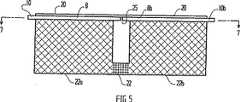
図5は、図7の線5−5に沿う側断面図で、本発明の第3の態様を示す。
図6は、端面図で図5の態様を示す。
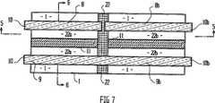
図7は、図5の線7−7に沿う図5の態様の平面図を示す。
好ましい態様の詳細な説明
図1を参照しながら本発明の第1の態様を示す。第1の態様は多孔質膜1を含んで成り、多孔質膜は、膜の上面2、膜の底面3、膜の側面4,5及び端面6,7の間で実質的に矩形のセル(電池)を規定する。多孔質膜1を、例えば、ポリスルホン又はポリビニリデンジフルオリドのシートから形成してよい。シートは、例えば、100μmの厚みがあってよく、孔の寸法は、例えば、0.2μmであってよい。
セルは、膜1の1つの側2の外側に、例えば、スパッタリングによって付着または蒸着した、例えば金又は白金等の金属の薄膜形態の第1の電極8を有する。第2の電極(参照電極)9を、例えば、第1の電極8に隣接して、膜1の同じ側2に電極8から離れた位置に、第1の電極8と同様にして形成する。別法では、電極9を、電極8との間でセルを規定する多孔質膜1の反対側3に形成してもよい。
電極8と9の間に障壁を形成するために、1又は2の一方または双方の側から多孔質膜1を圧縮することによって、電極8と9の間に拡散障壁11を形成する。図1の例において、障壁は片側からの圧縮によって形成され、電極8と9の中間において一端6から他端7に伸びている(図2)。膜1と共に電極を組み立てる、または膜1上に電極を付着する前又は後に障壁11を形成してもよいが、電極を形成する前に障壁11を形成するのが好ましい。隔壁11を形成するために圧力を選択的に加えて膜を圧縮する。その結果、得られる圧縮領域を横切るイオン拡散が、未圧縮膜を通過する拡散と比較して十分に減少するが、圧縮領域を横切る電気的接続には十分である程度まで、障壁領域の膜材料の密度を増加させる。本態様においては、これは、50−125KPaの範囲の圧力を加えることで達成される。別法では、限られた領域において膜の孔を化学的にブロック(阻止)することにより、又は本出願人の係属中の国際出願PCT/AU96/00210号において記載するように化学的及び物理的手段の組み合わせにより障壁11を形成してもよい。
第2の電極9は参照電極であり、例えば、スパッタリングによって付着する銀電極であってよく、次に、電極9を処理してハロゲン化銀を形成する、例えば、塩素を用いる処理、塩素イオンを含む溶液中における電気化学的な処理、次亜塩素酸塩を用いる処理、もしくは塩化物の存在下酸化剤を用いる処理、または塩化銀を形成するための他の処理に付し、あるいは酸化銀の表面を形成するために酸化するまたは自然に酸化させる。金属はハロゲンと反応して、その場所で金属/ハロゲン化金属参照電極、例えば、銀/塩化銀電極を形成する。驚くべきことに、このようにして形成した電極は、例えば、塩化物イオンまたは塩化物を含む溶液内に配置されると、30秒以内に、典型的には10秒以内に、定常状態の電位に達し得ることが見出された。参照電極は比較的非多孔質の表面を有するから、溶液との間で迅速に平衡状態になり、30秒以内に、より通常は10秒以内に定常状態の電位に達する。これは、量の少ない試料(例えば、数マイクロリットル)を用いる測定を容易にし、高い再現性と精度を提供する。
これによって、セルを、バッチ内及びバッチ間においてよりバラツキが従来よりも少なく、より安価に作製することもできる。さらに、測定を迅速に行えるので、pHの測定を、8以上のpHにおいてヒドロキノンレドックス系を用いて行うことができる。
望ましくは、電極8と9を、コネクター10と接続又は一体化して、電位又は電位差測定用装置(例えば、適当なインピーダンスを有する電圧計、図示せず)の相互に係合するコネクターと、本発明のアッセンブリを容易に電気的に接続することができる。
レドックス系、例えば、キノン−ヒドロキノン系を、例えば、障壁11を電極8の間で、膜の上又は中に付着する。そのような化学薬品を、例えば、溶液としてマイクロピペットを用いて付着し、次に溶媒を蒸発して乾燥付着物としてその化学薬品を残してよい。
本発明の好ましい態様において、2つの化学系を有するセルが提供され、例えば、銀/塩化銀を含んで成る参照電極8は、参照電極9に隣接して障壁11の側で膜内に乾燥塩化カリウムを有し、第1の電極8に隣接する障壁11の側は、膜内に付着するヒドロキノンを有する。電極間にイオン性の接続が許容されながらも、レドックス電極は、溶液の混合に対する障壁として機能する手段11によって参照電極から分離されているので、電極間の実質的な空間の必要性が避けられ、よりコンパクトなアッセンブリを作製できる。拡散障壁は実質的な混合を防止するべきであるが、イオンの拡散を完全には防止するべきではないことが理解されよう。イオンの実質的な量が、試験時間中に一方の電極から他方の電極へ拡散しない程度に、障壁が拡散を遅くすれば十分である。
図4を参照しながら、図1〜4の態様に類似する第2の態様を説明する。図4については、図1〜3の部分と対応する機能の部分を示すために同じ数字を用いる。図4の態様は図1の態様と異なり、電極8と9が膜1の上に向かい合う側に配置され、異なって膜と組み立てられる。図4の態様は、白金金属の薄膜8をスパッタリングによって付着したマイラーキャリアーフィルム(Mylar carrier film)20と組立てられた多孔質膜1を有し、膜20は膜1の片面に配置され、金属8は、膜1の表面2と接触する。銀のコーティング9がスパッタリングによって付着され、その表面が塩化銀に変えられた第2のマイラーキャリアーフィルム21を、塩化銀の表面9を膜1の第2の表面3と接触させて取り付ける。拡散障壁11を電極8と9の間に、図4の態様において膜1の両側を圧縮することによって形成するが、例えば、国際出願PCT/AU96/00210号に記載したように膜1の領域の選択的な化学的ブロッキング(阻止)又は圧縮によって、又は化学的処理及び圧縮の組み合わせによって形成してもよい。拡散障壁11は、実質的に膜1を2つの半セルに分割する。この場合も、11における圧縮及び/又は化学的処理の程度を選択的に調節して拡散速度を制御する。その結果、障壁11は混合に対する障壁として機能しつつ、イオン”橋”として機能する。図4に記載する態様においては、膜1は塩化銀参照電極9に隣接する障壁11の側で乾燥塩化カリウムを含み、白金電極8に隣接する障壁11の側では膜1はキノン/ヒドロキノンを含む。保護フィルム又はコーティング23を電極で覆っていない膜の面に設けてもよい。
好ましければ、電極8と9を他の配列で配置してよく、また、追加の参照又は他の電極を用いてもよい。
化学薬品をセルに注入して導入し、その後乾燥してもよいし、電極を配置する前又は後に、1又は2以上の膜表面に印刷してもよい。
電極はいずれかの適切な金属又は金属/レドックスの組み合わせを含んで成ってよいことが理解されよう。当業者にとって明らかなように、電極を、亜鉛、鉄、カドミウム、コバルト、ニッケル、錫、白金、パラジウム、銀、銅、炭素等で作製できる。白金、パラジウム及び金が第1の電極として好ましい。参照電極は、銀/ハロゲン化銀、又は金属/金属酸化物の系、例えばアンチモン、イリジウム、パラジウムがそれらの酸化物と接触している系であってよい。好ましいレドックス系はヒドロキノン/キノンであるが、他の既知のレドックス系を用いることができる。本発明の好ましい態様においては、スパッタリングで付着する電極用支持基材としてマイラーを使用するが、ガラス、セラミックス、又はプラスチックス組成物のような他の化学的に不活性で電気的に抵抗性の基材を用いてもよい。
銀をスパッタリングして付着した参照電極を上述したように処理して、塩化銀表面を形成することができる。同様の処理を、銀もしくは他の参照電極金属並びに他のハロゲン化もしくは酸化剤を用いて適用できる。
第3の態様を、図5〜7を参照しながら説明する。図5〜7において、図1〜3を参照して上述したセルと同様のセルを示す。図5〜7において、図1〜3の部分の機能に対応する機能を有する部分は、対応する数字で示した。第3の態様においては、膜を領域22(図5)において圧縮及び/又は化学的にブロックして、膜1を2つのセルの部分22a及び22bに分割する。隔壁22を、国際出願PCT/AU96/00210号に記載のように形成し、セル22aと22bの間の液体の拡散を有効に防止し、それにより、隔壁22は、電極8と9の間において各セルを半セルに実質的に分離する障壁11とは異なる機能を果たす。セル22bは、第2または独立した”参照”セルを提供する。キャリアーフィルム20上の第1の電極8をセル22a及び22bの中間の25において分割する。従って、セル22bは、電極8と同時に形成されるが、その後隣接するセル22aの電極8から電気的に絶縁される電極8bを有する。参照電極9bも電極9から電気的に絶縁されてもよいが、両方のセルに共通する単一の連続する参照電極を用いるのが好ましい(図7参照)。本態様においては、校正用化学薬品、例えば、緩衝剤を含んで成る化学薬品を、第2のセル22bに付着し、乾燥する。使用に際して、水分を第2のセルに加え、装置をコネクター10bを経由してEMF測定デバイスに接続し、その結果、第1の電極8bと参照セル22bの参照電極の間の電位差を測定することができ、それにより、装置を校正できる。このアッセンブリをコネクター10を用いてEMF測定デバイスに接続して、検体セル22aの電極8と9の間の電位差を測定できる。検体を第1のセル22aに添加し、検体を含むセル22aの電位を測定する。両方のセルの電位を同時に測定又は比較できるEMFデバイスと接続するように、リードを両方のセルから配置するのがより好ましい。セル22a及び22bの寸法を相当な精度で容易に再現でき、また、両方のセルを実質的に同時に構成するので、第1と第2のセルの間と同様に電極についてほとんどバラツキなく本発明の装置を製造することができる。その結果、検体の測定を相当な精度をもって行うことができる。
本発明に関するデバイスの製造において、ストリップの形態の連続する膜材料を所定間隔で圧縮及び/又は化学的ブロッキングによってセルに分割することができ、また、本明細書にて説明したように、各セルを仕切ることができる。連続形態で電極を適用することができ、望ましいように試薬を付着し、その後、包装のために、連続するストリップを引き続き個々のセル又はセルの組み合わせに切断することができる。
化学薬品を他の手段を用いて付着してもよく、例えば、ドットマトリックスプリンターヘッドを用いてセルの表面上又は中に印刷してもよい。EMF測定装置とのスパッタリング電極の電気的接続を容易にするために、本発明の実用的な態様ではプラグ又はソケットコネクターを設ける。リードを本発明のアッセンブリの一方の端部又は他の向かい合う端部から取り出してよい。必要であれば、温度測定デバイス、例えば熱電対又はサーミスターを装置の一体部分としてよい。必要であれば、各デバイス又は各バッチのサンプルを、化学薬品を導入する前に校正してよい。その場合、校正定数を導き出し、例えば、本発明の電極アッセンブリを電圧測定デバイスに接続する際に自動的に読み取られるバーコードとして、デバイスに印すことができる。これにより、電極の構成の変動に対して測定値を自動的に補正することが可能になる。
本明細書で説明したように作製される塩化銀電極を電池において標準塩化銀電極と接続すると、電位差は0.5ミリボルト以下となる。セル間のバラツキは極めて小さい。定常状態は、約2秒以内にはっきり得られる。キンヒドロンレドックス系を用いて8以上のpHにおいて、測定を行うことができる。キンヒドロンがそれほど反応しない間に、定常状態の読みを得るために要する時間が短いことを考慮すると、そのような測定は、pHが既知の溶液と比較して行うことができる。
本発明の教示から当業者にとっては明らかなように、本明細書において開示される本発明の範囲から離れることなく、1つの態様の特徴を他の特徴と組み合わせることができる。本明細書において、キンヒドロンと言う場合、ヒドロキノンとキノンの1:1混合物に限定されるものではなく、電極において所定のレドックス電位を達成するために十分なヒドロキノン及びキノンを含んで成るいずれの組成物を用いてもよいことが理解されよう。同様に、他のキノン、例えば、1,4−ナフトキノン、テトラクロロベンゾキノン、チモキノン、トルキノンに基づくレドックス系及び他のレドックス系を用いてもよい。
本発明の好ましい態様に関する装置は、持ち運びでき、大きな電力を必要としない。好ましい態様は、校正を要さず、外部校正溶液を要さない。好ましい態様においては、pH値は変動しないで1つのpH値を示す。測定を少量の試料、例えば、1マイクロリットルより少ない試料で行うことができる。
本明細書の教示から当業者にとっては明白であるように、本発明に関する装置を、水素イオン以外の特定のイオンの濃度、他の熱力学的変数、例えば自由エネルギー、電導度等の測定の使用に適用することができ、他の形態において、他の手段を用いて製造することができる。Field of Invention
The present invention relates to the measurement of the activity and / or concentration of ions in a solution containing ions.
Background of the Invention
In general, the measurement of ion activity or concentration, especially hydrogen ion activity or concentration (pH), is routine in the chemical industry and laboratories, and is increasingly required at home. (For example, judgments on chlorination of soil, pH, and pool can be exemplified).
In order to estimate the pH of the solution, litmus paper or universal test paper is used. Litmus paper is a piece of paper that is coated with one or more indicator dyes that change color depending on the pH of the sample in contact with the piece of paper. The piece of paper is compared with a color chart to estimate the pH. Litmus paper is relatively inexpensive and is discarded after use. Litmus paper is easy to use, requires no calibration, and can be carried more easily, but has low resolution, cannot be used for colored liquids, has user error, and cannot be used by people with color blindness is there.
The main method used for accurate measurement of pH is a pH meter. The pH meter is based on the measurement of electrode potential in a reversible galvanic or voltaic cell (or cell). A galvanic or voltaic cell consists of two electrodes that are in contact with the solution and are joined so that current flows when the electrodes are connected by an electrical conductor. There is a potential called “electrode potential” at the interface between the electrode and the solution. The electromotive force (EMF) of the battery is equal to the algebraic sum of the two electrode potentials (appropriately taking into account the sign of each potential difference). A reliable measurement of the EMF of such a battery requires the use of some form of potentiometer, for example a Wheatstone bridge circuit where the EMF is calibrated (or calibrated) to a known reference battery. Such a battery may be a chemical battery in which a chemical reaction takes place as a whole or a “concentration” battery that causes a change in energy by the transfer of solutes from one concentration to the other. In order for the electrical energy generated in a battery to be thermodynamically related to the process occurring in the battery, the battery should behave reversibly in a thermodynamic sense.
Such an electrochemical cell consists of two single electrodes or half cells. For example, a standard metal-metal ion electrode and a standard hydrogen electrode form a battery, which is described as follows:
The electrode potential varies with the ion activity. The basic equation governing the effect of ion activity on voltage is:
E = E0-(RT / nF) lnQ (2)
Where T is the temperature (K),
R = gas constant, 8.314 J · K-1・ Mol-1,
F = Faraday constant, 96486.7 C · equivalent-1,
n = number of electrons transferred in the described reaction,
Q = activity coefficient (corresponding to the following formula (3))
For the generalized reaction aA + bB = gG + hH (3)
Q = (aGgaHh) / (AAaaBb)
In a single connection liquid cell consisting of a hydrogen electrode and a reference electrode, for example a calomel (mercury chloride) electrode, the pH is
pH = pH (S) + (EES) / (2.3026RT / F) (4)
Defined by Here, E is an electromotive force (EMF) measured for an unknown solution in the cell, and R, T, and F are as defined above. Assign the pH value of the standard reference solution to pH (S). ESIs the EMF measured when this reference solution replaces the unknown solution in the cell described above.
For the description of hydrogen and other ion concentration measurements, three types of electrodes are used in the cell. The first type of reversible electrode comprises a metal or non-metal and is in contact with a solution of its own ions. For example, zinc in a zinc sulfate solution or copper in a copper sulfate solution. At least in principle, the non-metals that provide the reversible electrode are hydrogen, oxygen and halogen, and the corresponding ions are hydrogen ion, hydroxide ion and halide ion (or halogen ion), respectively. In these cases, the electrode material is non-conductive, often gaseous, so it quickly reaches parallel with hydrogen, oxygen, etc. Finely divided (or ground) platinum or other noble metals are used to make electrical contacts. The traditional hydrogen electrode, which is the main standard for all measurements of hydrogen ion concentration, is an example of this first type of electrode. It consists of a small sheet of platinum coated with platinum black. When used, the electrode is immersed in the solution and pure hydrogen is bubbled on the surface for at least 20-30 minutes. Hydrogen electrodes are important as a standard, but are not practical for daily use and are easily poisoned by materials such as arsenic, heavy metals, sulfides and cyanides.
The second type of electrode comprises a sheet or wire of metal and a sparingly soluble salt of the metal, which is in contact with a solution of a soluble salt of the same anion. An example is an electrode consisting of a soluble chloride solution such as silver, solid silver chloride and potassium chloride. These electrodes are common anions, in this case chloride ions (Cl-Behaves as if it is reversible. This type of electrode has been made using other insoluble halides, such as silver bromide and iodide, and soluble sulfates, oxalates, and the like. The calomel electrode is this type of electrode.
A third type of reversible electrode consists of a sheet of inert metal such as gold or platinum, for example Sn4+And Sn2+, Fe3+And Fe2+Or Fe (CN)63-And Fe (CN)6Four-In a solution containing both the oxidation and reduction states of the redox system ("redox" system). The oxidation and reduction states need not be ionic. For example, oxidation-reduction electrodes containing organic compounds, such as quinhydrone electrodes, are known. Quinhydrone is hydroquinone HOC6HFourOH and benzoquinone OC6HFourAn equimolar mixture of O. This dissociates into two components at 25 ° C. to the extent of about 93%. The electrode is formed by immersing an inert metal such as platinum or gold in a quinhydrone solution (usually a saturated solution).
It is necessary to prepare a new solution, and it is necessary to use freshly recrystallized quinhydrone in its preparation. The quinhydrone electrode was widely used in the 1920s, but when the calomel electrode was developed, it was quickly abandoned due to the inconvenience of preparing the quinhydrone electrode and the short solution life.
The development of glass pH electrodes has surpassed all previously used electrodes and has resulted in electrodes that enable practical pH meters that are widely used today. Glass electrodes can be used continuously in a mixture where hydrogen, quinone, and antimony electrodes are difficult to repeatedly give accurate results in the presence of heavy metals in an oxidizing or reducing medium. In its simplest form, the glass electrode consists of a thin-walled glass sphere and has an inner solution that immerses the reference electrode. For general use, the electrodes are usually formed by blowing a special glass (such as Corning 015 glass) that has a low melting point, high hygroscopicity, and relatively high electrical conductivity. The potential of the glass electrode depends on the composition of the inner solution and the nature of the inner electrode as well as the “asymmetry potential”. Glass electrodes are suitable for mass production, are quite durable and long lasting, so they are widely used for pH measurement. Meters using glass electrodes operate accurately and inexpensively. However, glass electrodes are inherently high resistance and require a voltmeter, and meters are not always portable. Furthermore, such pH meters require monotonous calibration that requires expensive operator time as well as the cost of the buffer consumed.
International application PCT / GB87 / 00857 discloses a hollow capillary filled cell with electrodes on the inner surface of the cell and "printed" reagents on the inner surface of the cell. The interelectrode distance is important because the cell is based on the spatial separation between the electrodes functioning as capillaries or frit. That is, the interelectrode distance must be such that the diffusion of ions from one electrode to the other is longer than the test or reference.
Object of the invention
The object of the present invention is to provide an inexpensive means of avoiding or at least mitigating the problems of the prior art and facilitating convenient measurement of pH. Preferred embodiments of the present invention are useful for estimating activity and / or concentration and / or redox potential of ionic species in solution.
Detailed Description of the Invention
According to one aspect of the present invention, the present invention provides:
A first electrode,
Reference electrode,
A porous membrane that holds a liquid analyte and extends between the first electrode and the reference electrode when introduced into the porous membrane in electrical contact with both of the electrodes described above,
A redox chemical system (as defined herein) contained in the porous membrane, and
Diffusion barrier (barrier) disposed between the electrodes
It exists in the cell (or battery) which has.
Desirably, a diffusion barrier is formed in the porous membrane by compressing the porous membrane and / or filling the pores of the porous membrane with an obstruction (or blocker). The degree of compression and / or the degree of pore plugging is selected to provide an electrical connection between the solutions on both sides of the barrier and to function as a frit despite being a barrier to diffusion. .
In our pending international application PCT / AU96 / 00210, the disclosure of which is incorporated herein by reference, forms a layer or coating region that adheres to a porous substrate. A method is described. The liquid moves through the barrier by compressing the substrate in one region of the substrate and / or closing the pores of the substrate, i.e. the region from one side of the substrate region to the other. A barrier is substantially prevented from moving to. As described in that application, the method is used to accurately define the boundaries of the electrode regions. It has been found that a barrier can be formed in a similar manner, and the barrier is resistant to ion diffusion, but allows the movement of electrons and can function similarly to a frit.
In a preferred embodiment, the present invention provides a single use disposable device comprising a “cell” having an integral electrode and comprising a dry redox chemical, the device comprising a waterproof container For example, in a foil or foil (or metal foil) bag. In use, the device is removed from the waterproof container and electrically connected to a potentiometer or EMF measuring device, for example by plug-socket connection. The test solution is added to the “target area (or predetermined area)” of the device and placed in the cell. The specimen dissolves the dry redox chemical and comes into contact with both electrodes. The potential difference between the electrodes can be measured using a potentiometer and displayed using analog or digital means continuously or at predetermined intervals. Devices comprising cells and electrodes can be used and discarded or recycled to recover components.
In a more preferred embodiment, the device further comprises a reference cell that may include redox chemical and buffer chemical. The buffer chemical may be in dry form and may be separated from the reservoir of distilled water, for example, by a barrier that can be broken. The barrier can be broken to dissolve the reference cell chemistry and the electrode adjacent to the reference cell can be calibrated. Alternatively, water may simply be placed into the reference cell from the outside when needed. Assuming that the electrode adjacent to the sample cell is the same as the electrode adjacent to the reference cell, the concentration of ions in the sample can be measured more accurately by measuring the EMF of both cells.
The cell according to the present invention can be used to measure pH, the concentration of other ions (eg, chlorine ions), perform ion activity estimation, conductivity measurement, free energy estimation, and potentiometric titration. Etc. can be used.
[Brief description of the drawings]
Various aspects of the invention will now be described by way of example with reference to the accompanying schematic drawings, which are not to scale.
FIG. 1 shows a first embodiment of the present invention in an elevational sectional view of the end along line 1-1 of FIG.
FIG. 2 shows a first embodiment of the present invention in a plan view from above.
FIG. 3 shows the embodiment of FIG. 1 in a side view.
FIG. 4 shows a second embodiment of the present invention in an elevational sectional view of the end.
FIG. 5 is a side cross-sectional view taken along line 5-5 of FIG. 7 and shows a third aspect of the present invention.
FIG. 6 is an end view showing the embodiment of FIG.
FIG. 7 shows a plan view of the embodiment of FIG. 5 along line 7-7 of FIG.
Detailed Description of the Preferred Embodiment
A first embodiment of the present invention is shown with reference to FIG. The first embodiment comprises a porous membrane 1, which is a substantially rectangular cell between the
The cell has a
In order to form a barrier between the
The
As a result, the cell can be manufactured at a lower cost with less variation than in the prior art within and between batches. Furthermore, since the measurement can be performed quickly, the pH can be measured using a hydroquinone redox system at a pH of 8 or higher.
Desirably, the
A redox system, such as a quinone-hydroquinone system, is deposited, for example, between the
In a preferred embodiment of the present invention, a cell having two chemical systems is provided, for example, a
With reference to FIG. 4, a second aspect similar to that of FIGS. For FIG. 4, the same numbers are used to indicate functional parts corresponding to those of FIGS. The embodiment of FIG. 4 differs from the embodiment of FIG. 1 in that the
If desired, the
Chemicals may be injected and introduced into the cell and then dried, or may be printed on one or more film surfaces before or after placing the electrodes.
It will be appreciated that the electrodes may comprise any suitable metal or metal / redox combination. As will be apparent to those skilled in the art, the electrodes can be made of zinc, iron, cadmium, cobalt, nickel, tin, platinum, palladium, silver, copper, carbon, and the like. Platinum, palladium and gold are preferred as the first electrode. The reference electrode may be a silver / silver halide or metal / metal oxide system, such as a system in which antimony, iridium, palladium is in contact with these oxides. The preferred redox system is hydroquinone / quinone, although other known redox systems can be used. In a preferred embodiment of the present invention, mylar is used as a support substrate for the electrode deposited by sputtering, but other chemically inert and electrically resistant such as glass, ceramics, or plastics compositions. A substrate may be used.
A reference electrode deposited by sputtering of silver can be treated as described above to form a silver chloride surface. Similar treatments can be applied using silver or other reference electrode metals and other halogenating or oxidizing agents.
A third aspect will be described with reference to FIGS. 5 to 7 show cells similar to those described above with reference to FIGS. 5-7, the part which has a function corresponding to the function of the part of FIGS. 1-3 was shown with the corresponding number. In a third embodiment, the membrane is compressed and / or chemically blocked in region 22 (FIG. 5) to divide membrane 1 into two
In the manufacture of a device in accordance with the present invention, continuous membrane material in the form of strips can be divided into cells by compression and / or chemical blocking at predetermined intervals, and as described herein, each cell Can be partitioned. The electrodes can be applied in a continuous form and the reagents can be applied as desired, after which successive strips can subsequently be cut into individual cells or combinations of cells for packaging.
Chemicals may be deposited using other means, for example, printed on or in the cell surface using a dot matrix printer head. In order to facilitate the electrical connection of the sputtering electrode with the EMF measuring device, a plug or socket connector is provided in a practical embodiment of the present invention. The lead may be removed from one end of the assembly of the present invention or the other opposite end. If necessary, a temperature measuring device such as a thermocouple or thermistor may be an integral part of the apparatus. If necessary, each device or each batch of samples may be calibrated before the chemical is introduced. In that case, a calibration constant can be derived and marked on the device, for example, as a bar code that is automatically read when the electrode assembly of the present invention is connected to the voltage measurement device. As a result, it is possible to automatically correct the measurement value with respect to variations in the electrode configuration.
When a silver chloride electrode fabricated as described herein is connected to a standard silver chloride electrode in a battery, the potential difference is 0.5 millivolt or less. The variation between cells is extremely small. Steady state is clearly obtained within about 2 seconds. Measurements can be made at a pH of 8 or higher using a quinhydrone redox system. Considering the short time required to obtain a steady state reading while the quinhydrone does not react so much, such a measurement can be made relative to a solution of known pH.
As will be apparent to those skilled in the art from the teachings of the present invention, the features of one aspect may be combined with other features without departing from the scope of the invention disclosed herein. As used herein, quinhydrone is not limited to a 1: 1 mixture of hydroquinone and quinone, but any composition comprising sufficient hydroquinone and quinone to achieve a predetermined redox potential at the electrode. It will be appreciated that may be used. Similarly, redox systems based on other quinones such as 1,4-naphthoquinone, tetrachlorobenzoquinone, thymoquinone, tolquinone and other redox systems may be used.
The device according to the preferred embodiment of the present invention is portable and does not require significant power. Preferred embodiments do not require calibration and do not require an external calibration solution. In a preferred embodiment, the pH value does not vary and shows a single pH value. Measurements can be made with small samples, eg, less than 1 microliter.
As will be apparent to those skilled in the art from the teachings herein, the apparatus according to the present invention can be used to measure the concentration of certain ions other than hydrogen ions, other thermodynamic variables such as free energy, conductivity, etc. In other forms, it can be manufactured using other means.
Claims (13)
Translated fromJapanese多孔質膜は、第1の電極と参照電極との間で延在し、両方の該電極と電気的接触状態で多孔質膜に導入した液体の検体を保持し、
拡散障壁は、多孔質膜内に形成されて、電極間のイオン拡散を阻止する障壁を形成するセル。Acell comprising a first electrode, a reference electrode, a porous membrane,and a diffusion barrier positioned between the electrodes,
The porous membrane extends between the first electrode and the reference electrode and holds a liquid specimen introduced into the porous membrane in electrical contact with both electrodes,
A diffusion barrier is a cell that is formed in a porous membrane to form a barrier that prevents ion diffusion between electrodes .
Applications Claiming Priority (3)
| Application Number | Priority Date | Filing Date | Title |
|---|---|---|---|
| AU2296 | 1996-09-13 | ||
| AUPO2296AAUPO229696A0 (en) | 1996-09-13 | 1996-09-13 | Analytic cell |
| PCT/AU1997/000599WO1998011426A1 (en) | 1996-09-13 | 1997-09-11 | Analytic cell |
Publications (2)
| Publication Number | Publication Date |
|---|---|
| JP2001500259A JP2001500259A (en) | 2001-01-09 |
| JP3751026B2true JP3751026B2 (en) | 2006-03-01 |
Family
ID=3796609
Family Applications (1)
| Application Number | Title | Priority Date | Filing Date |
|---|---|---|---|
| JP51305998AExpired - Fee RelatedJP3751026B2 (en) | 1996-09-13 | 1997-09-11 | Analysis cell |
Country Status (7)
| Country | Link |
|---|---|
| EP (1) | EP0929804B1 (en) |
| JP (1) | JP3751026B2 (en) |
| AU (1) | AUPO229696A0 (en) |
| CA (1) | CA2264288C (en) |
| DE (1) | DE69737627T2 (en) |
| ES (1) | ES2285739T3 (en) |
| WO (1) | WO1998011426A1 (en) |
Families Citing this family (17)
| Publication number | Priority date | Publication date | Assignee | Title |
|---|---|---|---|---|
| US6413410B1 (en) | 1996-06-19 | 2002-07-02 | Lifescan, Inc. | Electrochemical cell |
| US6863801B2 (en) | 1995-11-16 | 2005-03-08 | Lifescan, Inc. | Electrochemical cell |
| AUPN661995A0 (en) | 1995-11-16 | 1995-12-07 | Memtec America Corporation | Electrochemical cell 2 |
| US6632349B1 (en) | 1996-11-15 | 2003-10-14 | Lifescan, Inc. | Hemoglobin sensor |
| AUPO855897A0 (en) | 1997-08-13 | 1997-09-04 | Usf Filtration And Separations Group Inc. | Automatic analysing apparatus II |
| US6878251B2 (en) | 1998-03-12 | 2005-04-12 | Lifescan, Inc. | Heated electrochemical cell |
| US6652734B1 (en) | 1999-03-16 | 2003-11-25 | Lifescan, Inc. | Sensor with improved shelf life |
| US6444115B1 (en) | 2000-07-14 | 2002-09-03 | Lifescan, Inc. | Electrochemical method for measuring chemical reaction rates |
| KR100955587B1 (en) | 2001-10-10 | 2010-04-30 | 라이프스캔, 인코포레이티드 | Electrochemical cell |
| US20060134713A1 (en) | 2002-03-21 | 2006-06-22 | Lifescan, Inc. | Biosensor apparatus and methods of use |
| GB2470014A (en)* | 2009-05-05 | 2010-11-10 | Medermica Ltd | pH measurement device |
| DE102009024937A1 (en) | 2009-06-08 | 2010-12-09 | Braatz, Udo, Dr. | Method and arrangement for determining liquid parameters |
| DE102010040057A1 (en)* | 2010-08-31 | 2012-03-01 | Endress + Hauser Conducta Gesellschaft für Mess- und Regeltechnik mbH + Co. KG | Electrochemical sensor, particularly pH-sensor, comprises measuring electrode and reference electrode for generating reference potential |
| GB2490117B (en)* | 2011-04-18 | 2014-04-09 | Schlumberger Holdings | Electrochemical pH sensor |
| EP3227671B1 (en) | 2014-12-03 | 2021-02-24 | The Uwm Research Foundation, Inc. | Contaminant detection device and method |
| JP7730784B2 (en)* | 2022-04-23 | 2025-08-28 | キヤノン株式会社 | Microanalysis chip |
| JP7730785B2 (en)* | 2022-04-28 | 2025-08-28 | キヤノン株式会社 | Microfluidic Devices |
Family Cites Families (9)
| Publication number | Priority date | Publication date | Assignee | Title |
|---|---|---|---|---|
| US3616411A (en)* | 1968-09-16 | 1971-10-26 | Gen Electric | Partial pressure sensor |
| US4053381A (en)* | 1976-05-19 | 1977-10-11 | Eastman Kodak Company | Device for determining ionic activity of components of liquid drops |
| US4227984A (en)* | 1979-03-01 | 1980-10-14 | General Electric Company | Potentiostated, three-electrode, solid polymer electrolyte (SPE) gas sensor having highly invariant background current characteristics with temperature during zero-air operation |
| JPS6262259A (en)* | 1985-09-11 | 1987-03-18 | Fuji Photo Film Co Ltd | Ion activity measuring apparatus and measuring method using the same |
| EP0231033B1 (en)* | 1986-01-31 | 1991-01-02 | Fuji Photo Film Co., Ltd. | Device for measuring ion activity |
| DE3921526A1 (en)* | 1989-06-30 | 1991-01-10 | Draegerwerk Ag | DIFFUSION BARRIER WITH TEMPERATURE PROBE FOR AN ELECTROCHEMICAL GAS SENSOR |
| DE4312126A1 (en)* | 1993-04-14 | 1994-10-20 | Mannesmann Ag | Gas diffusion electrode for electrochemical cells |
| AU693678B2 (en)* | 1995-04-12 | 1998-07-02 | Lifescan, Inc. | Defining an electrode area |
| US5540827A (en)* | 1995-06-06 | 1996-07-30 | Johnson & Johnson Clinical Diagnostics, Inc. | Directional flow ion-junction bridge |
- 1996
- 1996-09-13AUAUPO2296Apatent/AUPO229696A0/ennot_activeAbandoned
- 1997
- 1997-09-11DEDE69737627Tpatent/DE69737627T2/ennot_activeExpired - Fee Related
- 1997-09-11JPJP51305998Apatent/JP3751026B2/ennot_activeExpired - Fee Related
- 1997-09-11ESES97938686Tpatent/ES2285739T3/ennot_activeExpired - Lifetime
- 1997-09-11CACA002264288Apatent/CA2264288C/ennot_activeExpired - Fee Related
- 1997-09-11WOPCT/AU1997/000599patent/WO1998011426A1/enactiveIP Right Grant
- 1997-09-11EPEP97938686Apatent/EP0929804B1/ennot_activeExpired - Lifetime
Also Published As
| Publication number | Publication date |
|---|---|
| EP0929804B1 (en) | 2007-04-18 |
| DE69737627D1 (en) | 2007-05-31 |
| JP2001500259A (en) | 2001-01-09 |
| EP0929804A4 (en) | 2000-07-26 |
| CA2264288C (en) | 2005-11-29 |
| EP0929804A1 (en) | 1999-07-21 |
| DE69737627T2 (en) | 2007-08-09 |
| ES2285739T3 (en) | 2007-11-16 |
| AUPO229696A0 (en) | 1996-10-10 |
| CA2264288A1 (en) | 1998-03-19 |
| WO1998011426A1 (en) | 1998-03-19 |
Similar Documents
| Publication | Publication Date | Title |
|---|---|---|
| JP3751026B2 (en) | Analysis cell | |
| Sophocleous et al. | A review of screen-printed silver/silver chloride (Ag/AgCl) reference electrodes potentially suitable for environmental potentiometric sensors | |
| EP0551769B1 (en) | Graphite base solid state polymeric membrane ion-selective electrodes | |
| AU638111B2 (en) | Polarographic chemical sensor with external reference electrode | |
| KR100358933B1 (en) | Planar reference electrode | |
| Hauser et al. | A potassium-ion selective electrode with valinomycin based poly (vinyl chloride) membrane and a poly (vinyl ferrocene) solid contact | |
| US5384031A (en) | Reference electrode | |
| JP3135956B2 (en) | Solid contact, potential difference sensor device using the same, and method using sensor device | |
| US6193865B1 (en) | Analytic cell | |
| Vamvakaki et al. | Solid-contact ion-selective electrode with stable internal electrode | |
| JP4005980B2 (en) | Potentiometric ion selective electrode | |
| Long et al. | Spectral Imaging and Electrochemical Study on the Response Mechanism of Ionophore‐Based Polymeric Membrane Amperometric pH Sensors | |
| CA2516921C (en) | Analytic cell | |
| AU719581B2 (en) | Analytic cell | |
| CA1116696A (en) | Ion-selective electrode | |
| Bruno et al. | Electroanalytical Chemistry | |
| Telting-Diaz et al. | a Potentiometry | |
| US6569304B1 (en) | Planar open reference electrode for use in voltammeric measuring chains | |
| RU2059237C1 (en) | Carbonate-selective electrode with internal solid contact | |
| Kahlert | Micro-reference electrodes | |
| Hilwa | Clinical Instrumentation Refresher Series: Ion Selective Electrodes | |
| Lowy et al. | Reference electrode for potentiometric analyses in corrosive media | |
| SU1040399A1 (en) | Fluoride ion activity measuring potentiometric pickup | |
| Patil et al. | Practical Physical Chemistry | |
| Davies | A simple mechanism, for which there is some good evidence, is in the reduction of oxygen at an iridium electrode. The reaction path appears to be |
Legal Events
| Date | Code | Title | Description |
|---|---|---|---|
| A711 | Notification of change in applicant | Free format text:JAPANESE INTERMEDIATE CODE: A711 Effective date:20040203 | |
| A72 | Notification of change in name of applicant | Free format text:JAPANESE INTERMEDIATE CODE: A721 Effective date:20040203 | |
| A131 | Notification of reasons for refusal | Free format text:JAPANESE INTERMEDIATE CODE: A131 Effective date:20041012 | |
| A521 | Request for written amendment filed | Free format text:JAPANESE INTERMEDIATE CODE: A523 Effective date:20050107 | |
| TRDD | Decision of grant or rejection written | ||
| A01 | Written decision to grant a patent or to grant a registration (utility model) | Free format text:JAPANESE INTERMEDIATE CODE: A01 Effective date:20051108 | |
| A61 | First payment of annual fees (during grant procedure) | Free format text:JAPANESE INTERMEDIATE CODE: A61 Effective date:20051206 | |
| R150 | Certificate of patent or registration of utility model | Free format text:JAPANESE INTERMEDIATE CODE: R150 | |
| FPAY | Renewal fee payment (event date is renewal date of database) | Free format text:PAYMENT UNTIL: 20091216 Year of fee payment:4 | |
| LAPS | Cancellation because of no payment of annual fees |