JP3750746B2 - Asymmetric artificial femoral joint - Google Patents
Asymmetric artificial femoral jointDownload PDFInfo
- Publication number
- JP3750746B2 JP3750746B2JP50669596AJP50669596AJP3750746B2JP 3750746 B2JP3750746 B2JP 3750746B2JP 50669596 AJP50669596 AJP 50669596AJP 50669596 AJP50669596 AJP 50669596AJP 3750746 B2JP3750746 B2JP 3750746B2
- Authority
- JP
- Japan
- Prior art keywords
- joint
- anterior
- distal
- femoral
- femoral component
- Prior art date
- Legal status (The legal status is an assumption and is not a legal conclusion. Google has not performed a legal analysis and makes no representation as to the accuracy of the status listed.)
- Expired - Lifetime
Links
- 210000000689upper legAnatomy0.000claimsabstractdescription49
- 210000003127kneeAnatomy0.000claimsabstractdescription41
- 210000004417patellaAnatomy0.000claimsdescription63
- 210000000629knee jointAnatomy0.000claimsdescription30
- 230000007246mechanismEffects0.000claimsdescription13
- 230000008859changeEffects0.000claimsdescription5
- 238000005452bendingMethods0.000claimsdescription4
- 230000008878couplingEffects0.000claims1
- 238000010168coupling processMethods0.000claims1
- 238000005859coupling reactionMethods0.000claims1
- 238000002271resectionMethods0.000description42
- 210000002303tibiaAnatomy0.000description28
- 210000000988bone and boneAnatomy0.000description18
- 230000007935neutral effectEffects0.000description14
- 238000000034methodMethods0.000description12
- 210000004439collateral ligamentAnatomy0.000description8
- 238000002679ablationMethods0.000description7
- 239000007943implantSubstances0.000description7
- 210000003041ligamentAnatomy0.000description7
- 241000469816VarusSpecies0.000description5
- 230000008901benefitEffects0.000description4
- 239000002184metalSubstances0.000description4
- 238000001356surgical procedureMethods0.000description4
- 238000011883total knee arthroplastyMethods0.000description3
- 210000003484anatomyAnatomy0.000description2
- 210000001061foreheadAnatomy0.000description2
- 230000005021gaitEffects0.000description2
- 210000004872soft tissueAnatomy0.000description2
- 208000010392Bone FracturesDiseases0.000description1
- 208000008924Femoral FracturesDiseases0.000description1
- 206010017076FractureDiseases0.000description1
- 206010062061Knee deformityDiseases0.000description1
- 230000015572biosynthetic processEffects0.000description1
- 238000002224dissectionMethods0.000description1
- 210000002683footAnatomy0.000description1
- 238000009434installationMethods0.000description1
- 238000013150knee replacementMethods0.000description1
- 239000000463materialSubstances0.000description1
- 230000004048modificationEffects0.000description1
- 238000012986modificationMethods0.000description1
- 230000000399orthopedic effectEffects0.000description1
- 230000009467reductionEffects0.000description1
- 230000004044responseEffects0.000description1
- 230000000630rising effectEffects0.000description1
- 230000007704transitionEffects0.000description1
Images


Classifications
- A—HUMAN NECESSITIES
- A61—MEDICAL OR VETERINARY SCIENCE; HYGIENE
- A61F—FILTERS IMPLANTABLE INTO BLOOD VESSELS; PROSTHESES; DEVICES PROVIDING PATENCY TO, OR PREVENTING COLLAPSING OF, TUBULAR STRUCTURES OF THE BODY, e.g. STENTS; ORTHOPAEDIC, NURSING OR CONTRACEPTIVE DEVICES; FOMENTATION; TREATMENT OR PROTECTION OF EYES OR EARS; BANDAGES, DRESSINGS OR ABSORBENT PADS; FIRST-AID KITS
- A61F2/00—Filters implantable into blood vessels; Prostheses, i.e. artificial substitutes or replacements for parts of the body; Appliances for connecting them with the body; Devices providing patency to, or preventing collapsing of, tubular structures of the body, e.g. stents
- A61F2/02—Prostheses implantable into the body
- A61F2/30—Joints
- A61F2/38—Joints for elbows or knees
- A61F2/3859—Femoral components
- A—HUMAN NECESSITIES
- A61—MEDICAL OR VETERINARY SCIENCE; HYGIENE
- A61F—FILTERS IMPLANTABLE INTO BLOOD VESSELS; PROSTHESES; DEVICES PROVIDING PATENCY TO, OR PREVENTING COLLAPSING OF, TUBULAR STRUCTURES OF THE BODY, e.g. STENTS; ORTHOPAEDIC, NURSING OR CONTRACEPTIVE DEVICES; FOMENTATION; TREATMENT OR PROTECTION OF EYES OR EARS; BANDAGES, DRESSINGS OR ABSORBENT PADS; FIRST-AID KITS
- A61F2/00—Filters implantable into blood vessels; Prostheses, i.e. artificial substitutes or replacements for parts of the body; Appliances for connecting them with the body; Devices providing patency to, or preventing collapsing of, tubular structures of the body, e.g. stents
- A61F2/02—Prostheses implantable into the body
- A61F2/30—Joints
- A61F2/38—Joints for elbows or knees
- A61F2/3877—Patellae or trochleae
Landscapes
- Health & Medical Sciences (AREA)
- Orthopedic Medicine & Surgery (AREA)
- Physical Education & Sports Medicine (AREA)
- Cardiology (AREA)
- Oral & Maxillofacial Surgery (AREA)
- Transplantation (AREA)
- Engineering & Computer Science (AREA)
- Biomedical Technology (AREA)
- Heart & Thoracic Surgery (AREA)
- Vascular Medicine (AREA)
- Life Sciences & Earth Sciences (AREA)
- Animal Behavior & Ethology (AREA)
- General Health & Medical Sciences (AREA)
- Public Health (AREA)
- Veterinary Medicine (AREA)
- Prostheses (AREA)
- Materials For Medical Uses (AREA)
- Steroid Compounds (AREA)
Abstract
Description
Translated fromJapanese本発明は、医療用人工補綴具に関し、特に、整形外科用人工補綴具に関する。より詳しくは、本発明は、人工関節内側大腿骨顆がより薄い内側部顆とより厚い外側後部顆を含み、その結果屈曲時、膝とともに後部内側大腿骨連結線を上昇させる改良型非対称人工膝関節と外科用インプラントの方法に関する。本発明は、また凹状近位前部位を有する。
関節形成は人工関節を生成することである。全膝の関節形成において、正確な解剖学的構造を再現するには困難がある。脛骨は通常、額面の軸に対し90°に切断されるが、脛骨高平台は約87°である。この不一致は、87°の切断を正確に再現する困難さに起因する。また、87°の切削または内反(varus)の切断によって、脛骨部品が緩む傾向にあることが報告されている(膝学会の会報1985-1986,ラスキン(Laskin),内反膝変形(Varus Knee deformity))、(膝の手術,インサルなど(Insall et al),1993)。
90°の切断によって、骨は脛骨の内側(ないそく)より外側(がいそく)でより多く取り除かれる。中立とは、無傷(摩損していない)の後部大腿骨顆に対する接線に平行と定義される。中立的大腿骨切断が行われ内側を外側で等しい厚さを有するイプラントが使用されると90°の屈曲において外側側副靭帯に緩みがおきる。外側側副靭帯が屈曲中に緩む理由は、脛骨の切除と大腿骨の後部切除が平行でないのにインプラントされる人工関節が、脛骨部品および大腿骨部品の後部顆で等しい内側と外側の厚さを有することにある。これによって内側でより小さい空間、外側でより大きい空間をもたらし、不均衡靭帯をおこす。
この問題の現在の解決法は、より多くの骨が後部内側大腿骨顆から取り除かれるように切断ブロックを回転することである。これは外方向回転と呼ばれる。外方向に回転(遠位端から見て左膝について時計方向回転)させることにより、後部大腿骨切除は、90°の脛骨切除に平行になる。この結果、側副靭帯は、人工関節がインプラントされたとき、伸展と屈曲において均衡になる。現在の業界基準は脛骨高平台の解剖学的角度87°と脛骨切除の90°間の3°の違いに相当する、外方向回転3°である。
この外科的処置の利点がこれまで記載されてきたがいくつかの欠点がある。大腿骨部品は、最大伸展時に脛骨部品ともはや整列(aligned)しなくなる。
大腿骨部品は、外側平面に平行に整列されると、脛骨に関して約3°で回転される。この不整列は、脛骨インサートに摩損を増加させるかもしれない。この不整列の可能な解決法は脛骨部品を外方向に回転させることかもしれないが、これは脛骨適用範囲を減らすことがあり、これは望ましくない。もう一つの解決法は、インサートをある角度に設計することかもしれないが、脛骨トレイ(tibial tray)を外方向に方向転換することも、それをインサート中に入れて設計することも屈曲時の不整列という問題をもつことになる。大腿骨部品を外方向に回転させることによって、脛骨トレイ又は脛骨インサートをまっすぐに整列させても外方向に回転させても、屈曲時もしくは伸展時に脛骨との不整列が起こる。
従来の外方向回転の第2の問題は外側前部大腿骨皮質を切痕(notching)する危険性である。
ノッチングは、中立切除より多くの骨が前部外側で取り除かれたときに起こり、切痕が大腿骨の前部皮質で生成される。
ノッチングは大腿骨骨折の危険性を大幅に増加させる。これに関連する問題は、前部内側のインプラント適用範囲の狭さまたはインプラントと骨のギャップでさえある。前部でのノッチングの危険性を減らすために、外側は皮質と揃えて位置させインプラントと骨間のギャップを前部内側で生じさせる。
従来の外方向回転のもう一つの問題は、装着時の増加した複雑さと困難さである。切断ブロックの配置は可変であるべきで、左膝と右膝に対して異なる設定がある。また、外科手術を行う際、30°外方向回転を正確に判断することはおそらく難しい。
現在、対称と非対称相方の大腿骨部品がある。対称部品のすべては、部品の中心線に沿って位置する膝蓋骨大腿骨溝を有する。非対称部品は、通常、角度をなすが直線の膝蓋骨大腿骨溝を有する。スミス アンド ネヒュー リチャード インコーポレイテッドから入手可能なGENESIS膝は、この非対称大腿骨設計タイプの一例である。どちらの設計を有する大腿骨部品の問題点は、膝蓋骨が外側に亜脱臼する傾向があること、または外側方向への引張りである。これは、膝蓋骨が部品の中心線に位置し、これが、解剖学的な膝蓋骨溝が位置するところより内側であるからである。外側方向に角度をなす膝蓋骨でさえ、膝蓋骨は、通常とは異なり、離れた外側をたどることはない。殆どの従来の大腿骨部品はより厚い外側前部フランジを有する。これは、膝蓋骨を外側に引っ張る支帯(retinacular)に張力を発生する。現在の外科的解決法は、膝蓋骨が正しい軌道を描くように軟組織を解離させることである。
膝蓋骨軌道は外方向回転で変更される。記載されたように部品を回転させることにより、外側前部フランジは低下し、膝蓋骨溝は外側に移動する。これは外側支帯の張力を減らすのに役立ち、膝蓋骨溝をより解剖学的な外側部の場所に位置させるのを助ける。0°から90°までの屈曲で、この屈曲範囲で膝蓋骨を外側に寄せることから利点が見つけられた。しかしながら、90°の屈曲の以後、膝蓋骨は内側に寄せられ、膝蓋骨において外側への力と剪断力を増加することがある。これは、骨インプラント中立面により高い応力を導き、膝蓋骨上において膝蓋骨インプラントを擦り減らすことになる。
現在の人工大腿骨関節は、外側からみて、凸状近位前部位を有する。これによって膝蓋骨及び/または靭帯が前部に置換される。凹状前部位を有することにより、凹状部位の金属が少なくなるので、膝蓋骨と靭帯は、より少なく前部で置換される。これで、解剖学的な大腿骨により近似し、膝蓋骨の軌道を改良することを助ける。
本発明の目的は、屈曲空間と伸展空間との均衡をとり、脛骨との適切な整列を維持し、90°脛骨切除と対称的な厚さの脛骨部品を用いた時前部大腿骨皮質を切痕しないことである。本発明のさらなる目的は、通常範囲の膝の動作中に膝蓋骨が正しく軌跡を描くのを可能にする、改良型人工大腿骨関節(人工大腿骨プロステーシス)を提供することである。
本発明は、全膝関節形成に使用するための改良型非対称人工大腿骨関節と、患者の遠位大腿骨に人工大腿骨関節をインプラントする改良方法を提供する。
本発明によれば、人工膝関節(人工膝プロステーシス)は、前部関節連結面と、外側顆面と内側顆面とを含む遠位および後部関節連結面部と内方向非関節連結面とを有する大腿骨部品と、使用中、大腿骨部品の関節連結面を収容する凹状関節連結面を有する脛骨部品からなり、内方向非関節連結面と外側顆部の関節連結面との距離が、少なくとも大腿骨部品の関節連結面の一部にわたって、内部非関節連結面と大腿骨部品の内側顆部の関節連結面との距離と、異なることにより、機構軸について大腿骨回転の角度が、通常範囲の膝の動作をうけて変化する。
好ましい実施例は、前部、遠位及び後部関節連結面を有する人工大腿骨関節を含む。後部関節連結面部は、前部非関節連結部または内方向面部から異なる距離に配置される一対の顆面を含む。後部外側関節面は、後部内側より前部非関節連結面から離れた距離にある。遠位部位における内側および外側関節面は、部品を横切る線から同じ距離である。
人工大腿骨関節は、切除された遠位大腿骨を収容するための複数の面を含む内方向非関節連結面を有する。好ましくは、非関節連結面は、一対の面取面と同様に、遠位、前部及び後部面を含む。付加的な切断面を備えてもよい。後部非関節連結面は、遠位大腿骨の同様の形に切除された表面にぴったり合う単一平面を形成することが好ましい。
脛骨部品は、使用中、大腿骨部品関節連結面を収容する凹状関節連結面を含む。
本発明の改良型人工大腿骨関節は、中立または外方向回転して整列された従来の大腿骨部品に伴う上述した問題を解決する。
本発明の人工大腿骨関節は、外方向に回転させた部品のように回転されないので、伸展時に脛骨を正しく整列する。この結果、大腿脛骨関節連結は改良され、厳しい摩損を減らす。
脛骨部品は外方向に回転されないので、屈曲時、大腿骨と脛骨部品間の回転に不適合がない。
ほぼ機構軸に対する大腿骨回転の角度は、大腿骨と脛骨の関節面の整列を維持しつつ、通常の範囲の動作で使う際、徐々に変化する。徐々の変化とは、関節の結合構造において、段差のあるまたは即時変化を生じない変化として定義される。患者が使用する通常な範囲の動きは、−10°から130°に及ぶだろう。水平面で歩行するとき、人は通常0°から70°の範囲である。歩行に関連する全体動作は歩様(gait)と呼ばれる。階段を上るために要求される動作範囲は、約0〜60°であり、階段を下るには、約0〜90°である。椅子からの立ち上がりは、0〜130°の範囲であり、深い膝の曲げは、0〜130°の範囲である。過伸展即ち負の屈曲は、約10°で立っている時に起こるかもしれない。
前部外側皮質は、追加して骨が取り除かれないから切痕されないはずである。前部大腿骨を切痕しない中立的切断が、使われる。人工関節は回転させないので、前部内側骨の適用範囲が改良される(前部内側にギャップがない)。
新しい大腿骨部品を差し込むための機器は、左右の膝に対し同じ手法を用い、3°の切除を位置決めをする仕事が除かれるため使用するのが簡単である。
本発明において厚さは、単に額面で角をなす遠位切除または中立回転に対して角度をなす後部切除を行うことによって、遠位と後部の両方で変更することができる。もし、前部切除が中立で行われ、後部切除が回転されるなら、前部から後部までの断面図は、台形状になるであろう。
内側間接面および外側関節面の位置の違いは、箱構造および遠位又は後部顆の厚さの変化から独立している。遠位または後部の切断は、同じ設計目的を達成するが額の厚さを一定にするか、もしくは異ならせるためにある角度でもしくは異なる高さで行うことができる。これは、脛骨と正しく整列させることで、屈曲空間と伸展空間を釣り合わせるという同じ結果を生じ、かつ、この新しい人工大腿骨関節の記載中とは異なる厚さを有する。
大腿骨部品は、また多少外方向回転を組み込んで設計してもよい。より外方向の回転を設計して、遠位と後部大腿骨の付加的に中立切除することによって、好ましい実施例の後部顆の厚さにより大きな差をつけてもよい。内側後部顆は、90°の屈曲において、大腿骨関節ラインが機構軸に沿って3°の回転角をなすように、大腿骨部品の外側後部顆より薄くする。約90°の屈曲において約1°から10°までの範囲で他の角度を大腿骨中に設計することができる。前記顆の関節結合構造は、大腿骨部品を横平面で脛骨インサートの配置に関して回転させる必要なく屈曲中および伸展中に大腿骨部品から脛骨部品と関節連結するように変化する。
不適当な膝蓋骨の軌道という問題を解決するために、本発明は、内方向非関節連結面と外方向関節連結面とを有する大腿骨部品を備えこの大腿骨部品は前部関節連結面と遠位および後部の外側および内側顆関節連結面を含み、大腿骨部品の中心線は部品の遠位顆間の中央に形成され、使用時に大腿骨部品の前部関節連結面と連結する関節連結面を有する膝蓋骨部品または自然の膝蓋骨を備え、前記大腿骨部品が前部関節連結面に、前記膝蓋骨が膝の標準的な関節連結時の動作中にたどることができる膝蓋骨溝を有し、溝の縦軸は、前部関節連結面の上位部位にある前記中心線に関して外側に位置され、大腿骨部品の前部関節連結面遠位部位で内側方向に曲がることからなる人工膝関節を提供する。
膝蓋骨溝は、膝蓋骨がより解剖的位置で動くように外側に移動させた。溝は前部部位の中心線の外側に位置し、その後、好ましくは部品の中心線と曲線を描く。膝蓋骨溝の外側への移動は、膝蓋骨が解剖学的位置で動くのを可能にし、膝蓋骨を外側に引く靭帯の張力を減らす。外側への移動は部品の幅によってのみ限定される。
新しい非対称大腿骨部品は、また外側から見て凹状の近位前部部位を有してもよい。この結果、この部位においてより薄い大腿骨部品になる。その利点は、インプラントの厚さが取り除かれた骨の厚さによりぴったりと合致することにある。余分な金属が大腿骨の前部皮質に追加されていないため、膝蓋骨と靭帯は、より解剖学的に機能する。凹状部位は部品の前方に位置する弧の中心を有するが、凸状部位は部品の前部面の後方に位置する弧の中心を有する。
本発明は患者の遠位大腿骨に人工大腿骨関節をインプラントする改良された方法を提供する。遠位大腿骨はまず、前部、後部、遠位及び一対の面取り切断を含む複数の5切断により切除される。人工大腿骨関節は患者の切除された遠位大腿骨に取り付けられる。人工大腿骨関節は、遠位大腿骨の前部、後部および遠位切断にぴったりと合う前部、後部、及び遠位非関節連結部を有する、改良型非対称人工関節である。
患者の脛骨の人工脛骨関節を収容するように切除される。大腿骨と脛骨切断は最大伸展時にほぼ平行になり、人工脛骨関節と人工大腿骨関節に関係し、ほぼ患者の機構軸についての脛骨に対する大腿骨回転の角度は、約−20°の屈曲のから約130°の屈曲までの患者の標準的な範囲の膝の動きを受けて、大腿骨と脛骨関節面の整列を維持しつつ徐々に変化する。
大腿骨後部切除は、無傷の後部大腿骨顆の接線に平行して実行され、ほぼ同量の骨が各後部顆から取り除かれるが、人工関節は外側後部顆より薄い内側後部顆を有する。遠位の厚さは、好ましい実施例では、内側顆と外側顆間で一定である。この結果、従来の人工大腿骨関節を外方向に回転させるのと同様に屈曲空間と伸展空間の両方を釣り合わせる。
本発明の性質と目的をさらに理解するため、添付の図面を用いて、本発明を例示するだけの以下の詳述な記載を参照していたがきたい。図面において同じ部品は同じ番号を示している。
図1は内側後部顆と外側後部顆の厚さと凹状前部部位を示す本発明の好ましい実施例の外側図である。
図2は本発明の装置の好ましい実施例の正面図である。
図3は人の大腿骨、膝関節、及び脛骨と足機構軸を示す正面図である。
図4は90°の脛骨切除と平行大腿骨切除とを示す人の膝関節の正面図である。
図5は87°の脛骨の解剖学的角度と90°の脛骨切除を図解する90°屈曲時の人の膝関節の正面図である。
図6は90°の脛骨切除を伴う大腿骨後部と前部の中立切除を図解90°屈曲時の膝関節の正面図である。
図7は中立整列において対称的厚さの脛骨と人工大腿骨関節を示す90°屈曲時の人の膝関節の正面図である。
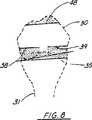
図8は前部と後部の大腿骨上の外方向に回転した切除を図解し、前部外側大腿骨と後部内側大腿骨から多くの骨を取る切断を示す人の膝関節の正面図である。
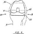
図9は外方向に回転した対称的厚さの脛骨および人工大腿骨関節と釣り合った側副靭帯を有する90°屈曲時の膝関節の正面図である。
図10は従来技術の膝関節置換外科処置の一部として、前部皮質で切痕をうけた大腿骨を図解をする外側図である。
図11は本発明の方法を用いた膝関節切除を図示し、並行な伸展空間を示す。
図12は本発明の方法を用いた中立大腿骨切除を図示し、台形状をしている伸展空間を示す。
図13は前部皮質と後部顆の中立大腿骨切除を示す90°屈曲時の膝関節の正面図である。
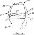
図14は後部外側より薄い後部内側顆および釣り合った側副靭帯を示す90°屈曲時の膝関節の本発明の好ましい実施例の正面図である。
図15は後部で異なる内側および外側曲線を示す本発明の非対称部品の好ましい実施例の外側図である。
図16は中立大腿骨切除を示す本発明の方法と装置の別の実施例の90°屈曲時の膝関節の正面図である。
図17は内側部である薄い外側部を有する脛骨部品を備えた本発明の装置の別の実施例を示す90°屈曲時の膝関節の正面図である。
図18は遠位で異なる内側と外側曲線を示す本発明の非対称大腿骨部品の別の実施例の外側図である。
図19は従来の凸状前部と凹状前部部位を示す大腿骨部品の外側図である。
図20は中央に配置された膝蓋骨溝を示す従来技術の大腿骨部品の正面図である。
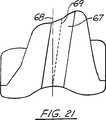
図21は角度をなす膝蓋骨溝を示す従来技術の大腿骨部品の正面図である。
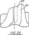
図22は本発明の改良型大腿骨部品の正面図である。
図23は膝蓋骨の位置を示す同様の図である。
図24は膝蓋骨溝の位置を示す改良型大腿骨部品の遠位図である。
図25は膝蓋骨溝を示す改良型大腿骨部品の内側図である。
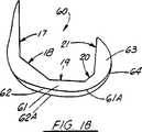
図1と図2は数字10で全体的に示す本発明の装置の好ましい実施例の概略を示す。非対称大腿骨部品10は、前部関節連結面部12、遠位関節連結面15、及び後部顆面13Aを有する外側後部顆13と、後部顆面14Aを有する内側後部面顆14とを含む一対の顆面とからなる人工関節の関節連結面11を含む。
非対称人工大腿骨関節10の近位側は、複数の面17−21と適合させて、患者の遠位大腿骨を切除した後にその遠位大腿骨を収容する凹所16を提供する。前部近位面17は近位の前部面取部18に交差する略平面である。前部面取部18は、前部近位面17と近位面19の間にわたっている。近位後部面取部20は、面19と後部近位面21とにわたっている。図2において、非対称人工大腿骨関節10は外側遠位面23と内側遠位面24と間に中央凹所部22を有する。
図1において、面13Aと面14Aの位置に差が見られる。外側後部顆13の最後部に接し額面に略平行に引かれた接線が、線13Bとして示されている。後部顆面14Aの最後部点に接して(額面に略平行に)引かれた接線が、線14Bである。線13Bと線14B間の距離25が、外側後部顆13が内側後部顆14より厚いことを示す。一方、顆13と14のそれぞれの内面21が同じ平面21であり、患者の遠位大腿骨の対応する切除面を受け入れる面を形成している。額面即ち前頭面は、線12Cを通りページに垂直な面として図1に示される。それは身体を前半分と後半分に分割する面である。横平面は、通常ウエスト領域を通り、身体を上半身と下半身に分ける面である。便宜上、それは線12Dを通りページに垂直な面として図1に示される。この平面は通常の横平面に平行であり、この記載では機能的に同じである。
大腿骨部品10には、3°の外方向への回転が、本来組み込まれている。これは外科医が3°外方向へ回転させて大腿骨を切断する現行の手順と対照的である。本発明の大腿骨部品10上では、機構軸32にほぼ対する大腿骨回転の角度は、患者の膝の標準的な範囲を動作を通じて、通常約0°の屈曲度から約90°〜130°の屈曲度まで徐々に変化する。患者が使用する動作の標準的な範囲は、−10°から130°までの範囲であろう。人が水平な面を歩行するとき、通常0°から70°の範囲である。歩行に関連する全動作は、歩様と呼ぶ。階段を上るために要求される動作範囲は、約0〜60°であり、階段を下るのは、約0〜90°である。椅子からの立ち上がりは、0〜90°の範囲、深い膝の曲げは、0〜130°の範囲であろう。過伸展即ち負の屈曲は、約10°で起立中に起こることもある。前記回転は、屈曲と伸展において外側平面に対し平行に大腿骨部品関節面を整列させるのと同様に大腿骨と脛骨部品間の屈曲ギャップを均衡にする。3°の外方向回転は概ね大腿骨の機構軸32に沿ってである。
全膝の関節形成において、正確な解剖学的構造を再現するには困難がある。図4と図5に図解されているように、患者の脛骨は、通常、額面の軸に対し90°に切断されるが、脛骨高平台は約87°である。この不一致は、87°の切断を正確に再現する困難さに起因する。また、87°の切断または内反(varus)切断によって、脛骨部品が緩む傾向にあることが記載されている(膝学会の会報1985-1986,ラスキン(Laskin),内反膝変形(Varus Knee deformity))。
図3、図4及び図5に示されるように、90°の切断によって、骨は脛骨の内側34より外側33の方が多く取り除かれる。図4には、脛骨切断は35として指示されている。このため、90°の屈曲において、等分に大腿骨の切断が行われる場合、脛骨の切除35と大腿骨の後部切除38、39が平行でなくなる。これは、内側34で空間が小さく、外側33で空間が大きくなる結果を生じ、これによって内側と外側で対称的な厚さを有する、従来の脛骨と大腿骨部品が用いられた場合、靭帯40、41が不均衡になる(図7参照)。
この問題の現在の解決は、切断ブロックを回転させて後部内側大腿骨顆からより多くの骨が取り除くことである。これが、この技術で外方向回転と呼ばれる。外方向に回転(遠位端から見て左膝について時計方向回転)させることにより、後部大腿骨切除は、90°の脛骨切除に平行になる(図8参照)。この結果、側副靭帯40と41は、図9に示されるように、人工関節がインプラントされたとき、伸展と屈曲において均衡になる。現在の業界基準は、3°の外方向回転である。
この従来の外方向回転の一つの問題は、図10に従来技術の人工大腿骨関節Fと人工脛骨関節Tと共に図示されているように、外側前部大腿骨皮質を切痕する危険性である。図8は、図6に示される大腿骨の等分切除より多くの骨が前部外側と後部内側で取り除かれることを示す。図10は、大腿骨が折れる危険性を大きく増す、ノッチ43を伴う前部皮質42を図解している。
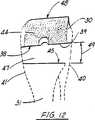
好ましい実施例において、大腿骨後部切除は等分に行われ、各後部顆からほぼ同量の骨が取り除かれるが、人工関節は、図14で示されるように、その外側後部顆13より薄い内側後部顆14を有する。遠位厚さは、図15に示される好ましい実施例において、内側顆と外側顆間で同じである。これは、従来の人工大腿骨関節を外方向に回転することと同様に、屈曲空間と伸展空間の両方を均衡にする。図11、図12は、本発明の方法に適用した等分大腿骨切除を示す。遠位大腿骨切除は44、脛骨切除は45として示され、平行な伸展空間46を形成している。前部切除は、図11と図12において48として示されている。図12において、後部大腿骨切除38と39は膝が屈曲状態であるとき現れ、台形状屈曲空間47を形成する
もう一つの方法と装置が図16〜18に示される。本発明の方法と装置のこの別の実施例は、90°の脛骨切除51と、内側より外側の方が厚い脛骨部品50を用いている。そこで、大腿骨部品60は、内側遠位顆62より薄い外側遠位顆61を有するであろう。そこで、後部顆63と64は、この別の実施例において、屈曲時約90°の同じ厚さを有するであろう。
本発明によれば、単に額正面で角をなす遠位切除、または等分回転に関して角をなす後部切除を行うことによって、厚さと遠位と後部の両方で、変えることができるだろう。もし、前部切除が等分に行われ、後部切除が角度をなすなら、前部から後部への断面が、横平面に台形状になる。
図13〜18に示される非対称人工大腿骨関節部品10と60は、内側と外側との違いが箱型構造とは無関係に、遠位顆の厚さがどのようにも変化することにあることを示す。遠位切断または後部切断は、同じ設計目的を達成するが一定の顆の厚さを維持する、または異なる顆の厚さを維持するために、ある角度、または異なる平面で行うことができる。これは、脛骨との適切な配列によって屈曲空間と伸展空間を均衡にするという同じ結果を生じ、この新しい人工大腿骨関節の記載とは異なる顆の厚さを有するだろう。
大腿骨部品は幾分かの外方向回転を組み込んで設計されることもできる。遠位と後部の大腿骨の従来の等分切除では、後部人工関節の顆の厚さの差が大きくなれば、より大きな外方向回転を生成する。
新しい大腿骨部品の設計は、90°の脛骨切除を補正するように位置させることを意図している。額面で90°で脛骨を切除し、内側と外側で同じ厚さを有する、人工関節脛骨部品を位置させることは、脛骨の内側部が高くなる結果になる。これを補正するため、本発明の大腿骨部品は、遠位と後部の大腿骨切除と共に、大腿骨に関する内側関節ラインを上げて脛骨に起こるこの上昇を補正する。
後部大腿骨については、これは、後部大腿骨顆関節ラインに対しほぼ平行に、後部大腿骨を切除することによって達成される。人工関節内側大腿骨顆は内側に起こる切除より薄い。このことによって、屈曲において膝と一緒に後部内側大腿骨関節ラインが上昇する結果になる。
大腿骨の遠位切除は大腿骨の内側顆と外側顆から非対称の量の骨を取り除くことにより達成される。遠位内側面と外側面は、そこで、同じ厚さの人工関節内側面と外側面に置き換えられる。
追加の骨が内側遠位大腿骨顆から取り除かれるので、これは、屈伸時の膝に内側遠位大腿骨関節ラインの上昇を引き起こす。これもまた、額面で90°の脛骨切除により起こる脛骨の内側部の上昇に対し補正する。
図19は大腿骨部品の外側図を示す。前部部品65は、弧の中心が部品の前部に設定されている新大腿骨の凹状部位を示す。前部部位66は、弧の中心が前部面に対し後部に設定されている従来の大腿骨部品の凸状部位を示す。図19に示すように、この凹状前部は前部の金属を減らす結果になり、切除された骨を同量の金属でより密接に置き換える。
図20と21は、膝蓋骨溝67が、大腿骨部品の中心線68に関して中央に位置選定されているか(図20)、または角度をなしている(図21)従来技術の人工関節を示す。
一方、図22の改良された大腿骨部品は、膝蓋骨溝を有する、部品の前部部位65の中心線68の外側でかつこの線にほぼ平行に位置選定され、次に、顆内ノッチ70で中心線68の方に曲げれている。溝67の深さは、図25に線72で示される。膝蓋骨大腿骨溝を外側に置くことにより、靭帯はさらに均衡化され、膝蓋骨はより滑らかにより正確に膝蓋骨大腿骨溝をたどることができる。新設計は、前部部位でほぼ真っすぐにではあるが中心線の外側にずれて配置され、そして顆内ノッチ部位中に徐々に転移する膝蓋骨大腿骨溝である。このタイプの膝蓋骨大腿骨溝設計は、中心線または角度をなす膝蓋骨大腿骨溝設計に比較して、より高い屈曲度ではるかに外側に膝蓋骨を動かす。これは、軟組織の外側への解離の必要性を避けるべく膝蓋骨を適切に動かせるため、臨床上の利点になる。膝蓋骨は、図24に示される顆内ノッチにおいて部品の中心線へと徐々に転移する前に、約40〜50°の屈曲まで外側を動くことができる。高度の屈曲において大腿骨部品と膝蓋骨とが十分に接触するため、顆内ノッチに転移する。
次に示す表に、この明細書および添付の図面に使用する部品番号と部品の説明をあげる。
部品表
部品番号 記載
10 非対称人工大腿骨関節(asymmetrical femoral prosthesis)
11 人工関節の関節連結面(prosthesis articulating surface)
12 前部関節連結面(anterior articulating surface)
12A 前部接線(anterior tangent line)
12B 前部凹状面(anterior concave surface)
12C 額面(frontal plane)
12D 横平面(transverse plane)
13 外側後部顆(lateral posterior condyle)
13A 後部顆面(posterior condyar surface)
13B 後部外側接線(posterolateral tangent line)
14 内側後部顆(medial posterior condyle)
14A 後部顆面(posterior condylar surface)
14B 内側接線(medial tangent line)
15 遠位面(distal surface)
16 近位窩(proximal recess)
17 前部近位面(anterior proximal surface)
18 近位前部面取部(proximal anterior chamfer)
19 近位面(proximal surface)
20 近位の後部面取部(proximal posterior chamfer)
21 後部近位面(posterior proximal surface)
22 窩(recess)
23 外側遠位面(lateral distal surface)
24 内側遠位面(medial distal surface)
25 オフセット距離(offset distance)
26 内側遠位面(medial distal surface)
27 外側遠位面(lateral distal surface)
28 角度(angle)
29 解剖的角度の脛骨(anatomical angle tibia)
30 大腿骨(femur)
31 脛骨(tibia)
32 機構軸(mecanical axis)
33 外側(lateral side)
34 内側(medial side)
35 90°の脛骨切除(ninety degree tibial resection)
36 遠位大腿骨切除(distal femoral resection)
37 伸展空間(extension space)
38 大腿骨切除−後部内側(femoral resection-posteromedial)
39 大腿骨切除−後部外側(femoral resection-posterolateral)
40 外側側副靭帯(lateral collateral ligament)
41 内側側副靭帯(medial collateral ligament)
42 前部大腿骨皮質(anterior femoral cortex)
43 切痕(notch)
44 遠位大腿骨切除(distal femoral resection)
45 脛骨切除(tibial resection)
46 伸展空間−平行(extension space-parallel)
47 屈曲空間−台形(flexion space-trapezoidal
48 前部切除(anterior resection)
49 角度(angle)
50 脛骨部品(tibial component)
51 脛骨切除(tibial resection)
F 人工大腿骨関節(femoral prosthesis)
T 人工脛骨関節(tibial prosthesis)
60 大腿骨部品(femoral component)
61 外側遠位顆(lateral distal condyle)
61A 外側遠位面(lateral distal surface)
62 内側遠位顆(medial distal condyle)
62A 内側遠位面(medial distal surface)
63 後部外側顆(posterolateral condyle)
64 後部内側顆(posteromedial condyle)
65 新非対称大腿骨の凹状前部部位
66 従来の大腿骨の凸状前部部位
67 膝蓋骨溝(patella groove)
68 大腿骨部品の中心線(centerline of femoral component)
69 膝蓋骨溝の縦軸(longitudinal axis of patella groove)
70 顆内切痕(intracondylar notch)
71 膝蓋骨部品(patella component)
72 膝蓋骨溝の深さを示す線
ここに教示される本発明の概念の範囲内で数多くの種々な異なる実施態様が可能で、法による記載要件に従ってここに詳述された実施例に多くの改変が可能であることから、ここに記載の詳細は例示のためのものであって発明を制限する意味ではないと解釈されるべきであることを理解すべきである。The present invention relates to a medical prosthesis, and more particularly to an orthopedic prosthesis. More particularly, the present invention relates to an improved asymmetric artificial knee in which the prosthetic medial femoral condyle includes a thinner medial condyle and a thicker lateral posterior condyle, thereby raising the posterior medial femoral connection line with the knee when flexed. It relates to the method of joints and surgical implants. The present invention also has a concave proximal anterior site.
Joint formation is the creation of an artificial joint. In total knee arthroplasty, it is difficult to reproduce the exact anatomy. The tibia is usually cut at 90 ° to the face axis, while the tibial plateau is about 87 °. This discrepancy is due to the difficulty of accurately reproducing the 87 ° cut. In addition, it has been reported that the tibial component tends to loosen due to 87 ° cutting or varus cutting (Journal of the Knee Society 1985-1986, Laskin, varus knee deformation (Varus Knee) deformity)), (surgery of the knee, Insall et al., 1993).
With a 90 ° cut, more bone is removed on the outside of the tibia than on the inside of the tibia. Neutral is defined as parallel to the tangent to the intact (unworn) posterior femoral condyle. When a neutral femoral cut is made and an implant having equal thickness on the inside and outside is used, the lateral collateral ligament loosens at 90 ° flexion. The reason for the lateral collateral ligament to loosen during flexion is that the prosthesis to be implanted while the tibial resection and the posterior resection of the femur are not parallel have equal medial and lateral thickness at the tibial component and the posterior condyle of the femoral component It is in having. This results in a smaller space on the inside and a larger space on the outside, creating an unbalanced ligament.
The current solution to this problem is to rotate the cutting block so that more bone is removed from the posterior medial femoral condyle. This is called outward rotation. By rotating outward (clockwise rotation about the left knee as viewed from the distal end), the posterior femoral resection is parallel to the 90 ° tibial resection. As a result, the collateral ligament is balanced in extension and flexion when the prosthesis is implanted. The current industry standard is an outward rotation of 3 °, which corresponds to a 3 ° difference between an anatomical angle of 87 ° for the tibial plateau and 90 ° for tibial resection.
While the advantages of this surgical procedure have been described so far, there are several drawbacks. The femoral component is no longer aligned with the tibial component at maximum extension.
When the femoral component is aligned parallel to the lateral plane, it is rotated about 3 ° with respect to the tibia. This misalignment may increase wear on the tibial insert. A possible solution for this misalignment may be to rotate the tibial component outward, but this may reduce the tibial coverage, which is undesirable. Another solution might be to design the insert at an angle, but turn the tibial tray outward, design it into the insert, It will have the problem of misalignment. Rotating the femoral component outward causes misalignment with the tibia when flexing or extending, whether the tibial tray or tibial insert is aligned straight or rotated outward.
A second problem with conventional outward rotation is the risk of notching the lateral anterior femoral cortex.
Notching occurs when more bone is removed outside the front than a neutral resection, and a notch is created in the anterior cortex of the femur.
Notching greatly increases the risk of femoral fractures. A problem associated with this is the narrow implant coverage inside the anterior region or even the implant-bone gap. In order to reduce the risk of notching at the front, the outside is aligned with the cortex, creating a gap between the implant and the bone inside the front.
Another problem with conventional outward rotation is the increased complexity and difficulty in installation. The placement of the cutting block should be variable and there are different settings for the left and right knees. Also, it is probably difficult to accurately determine 30 ° outward rotation when performing surgery.
Currently, there are symmetric and asymmetrical femoral components. All of the symmetrical parts have a patella femoral groove located along the centerline of the part. Asymmetric parts typically have an angled but straight patella femoral groove. The GENESIS knee, available from Smith and Nephew Richard, Inc., is an example of this asymmetric femoral design type. The problem with the femoral component with either design is the tendency of the patella to sub-dislocation outward or pulling outward. This is because the patella is located at the centerline of the part, which is more inside than where the anatomical patella groove is located. Even with a patella angled outwardly, the patella does not follow the outside, unlike normal. Most conventional femoral components have a thicker outer front flange. This creates tension in the retinacular that pulls the patella outward. The current surgical solution is to dissociate the soft tissue so that the patella follows the correct trajectory.
The patella trajectory is changed by outward rotation. By rotating the part as described, the outer anterior flange is lowered and the patella groove is moved outward. This helps reduce the lateral strut tension and helps to position the patella groove at a more anatomical lateral location. Advantages were found from 0 ° to 90 ° bends by bringing the patella outward in this bend range. However, after a 90 ° bend, the patella is brought inward and may increase outward and shear forces in the patella. This leads to higher stress on the neutral surface of the bone implant and wears down the patella implant on the patella.
Current artificial femoral joints have a convex proximal anterior site when viewed from the outside. This replaces the patella and / or ligament with the anterior portion. By having a concave anterior portion, less metal is in the concave portion, so less patella and ligaments are replaced at the front. This will help to better approximate the anatomical femur and improve the trajectory of the patella.
The purpose of the present invention is to balance the flexion and extension spaces, maintain proper alignment with the tibia, and remove the anterior femoral cortex when using 90 ° tibial resection and symmetrical thickness tibial components. Do not cut. It is a further object of the present invention to provide an improved prosthetic femoral joint (prosthetic femoral prosthesis) that allows the patella to correctly trace during normal range knee movement.
The present invention provides an improved asymmetric prosthetic femoral joint for use in total knee arthroplasty and an improved method of implanting an artificial femoral joint in a patient's distal femur.
According to the present invention, an artificial knee joint (artificial knee prosthesis) has an anterior joint connection surface, distal and rear joint connection surfaces including an outer condyle surface and a medial condyle surface, and an inward non-joint connection surface. A tibial component having a femoral component and a concave articulating surface that accommodates the articulating surface of the femoral component in use, wherein the distance between the inward non-articulating surface and the joint surface of the lateral condyle is at least the thigh Due to the different distance between the internal non-articulated joint surface and the articular joint surface of the medial condyle of the femoral component over a part of the articulating surface of the bone component, Changes in response to knee movement.
The preferred embodiment includes an artificial femoral joint having an anterior, distal and posterior articulating surfaces. The posterior joint connection surface portion includes a pair of condylar surfaces disposed at different distances from the front non-joint connection portion or the inward surface portion. The rear outer joint surface is at a distance from the front non-joint connection surface from the rear inner surface. The medial and lateral articular surfaces at the distal site are the same distance from the line across the part.
The artificial femoral joint has an inward non-articulating surface that includes a plurality of surfaces for receiving the resected distal femur. Preferably, the non-articulating surface includes a distal, anterior and posterior surface as well as a pair of chamfered surfaces. Additional cut surfaces may be provided. The posterior non-articulating surface preferably forms a single plane that fits the similarly shaped surface of the distal femur.
The tibial component includes a concave articulating surface that, in use, accommodates the femoral component articulating surface.
The improved artificial femoral joint of the present invention solves the above-mentioned problems associated with conventional femoral components that are aligned in neutral or outward rotation.
The prosthetic femoral joint of the present invention is not rotated like the part rotated outwardly, so that the tibia is correctly aligned during extension. As a result, the femoral-tibial articulation is improved and reduces severe wear.
Since the tibial component is not rotated outward, there is no incompatibility in rotation between the femur and the tibial component when flexed.
The angle of femoral rotation with respect to the mechanical axis gradually changes when used in the normal range of motion while maintaining the alignment of the articular surfaces of the femur and tibia. Gradual change is defined as a change in the joint structure that does not cause a step or immediate change. The normal range of motion used by the patient will range from -10 ° to 130 °. When walking on a horizontal plane, a person usually ranges from 0 ° to 70 °. The overall movement related to walking is called gait. The operating range required to go up the stairs is about 0-60 °, and to go down the stairs is about 0-90 °. The rise from the chair is in the range of 0-130 °, and the deep knee bend is in the range of 0-130 °. Overextension, or negative bending, may occur when standing at about 10 °.
The front lateral cortex isAdd The bone should not be removed because it is not removed. Neutral cuts that do not cut the anterior femur are used. Since the prosthesis is not rotated, the coverage of the anterior medial bone is improved (Front inside No gap).
New femoral partsPlug Equipment for the left and right knees is the sameUsing method It is simple to use because the work of positioning the 3 ° ablation is eliminated.
In the present invention, the thickness can be varied both distally and posteriorly by simply performing a distal ablation that is angled at the face or a posterior ablation that is angled to neutral rotation. If the front ablation is performed neutral and the posterior ablation is rotated, the cross-sectional view from the front to the rear will be trapezoidal.
The difference in position between the medial indirect surface and the lateral articular surface is independent of changes in the box structure and the thickness of the distal or posterior condyles. Distal or posterior cuts can be made at an angle or at different heights to achieve the same design objective but with a constant or different forehead thickness. This results in the same result of balancing the flexion and extension spaces with proper alignment with the tibia and has a different thickness than that described for this new artificial femoral joint.
The femoral component may also be designed to incorporate some outward rotation. A more outward rotation may be designed to make a greater difference in the thickness of the posterior condyles of the preferred embodiment by additional neutral resection of the distal and posterior femurs. The medial posterior condyle is thinner than the lateral posterior condyle of the femoral component so that at 90 ° flexion, the femoral joint line makes a 3 ° rotation angle along the mechanism axis. Other angles can be designed into the femur in the range of about 1 ° to 10 ° at a flexion of about 90 °. The condylar articulation structure changes to articulate from the femoral component to the tibial component during flexion and extension without having to rotate the femoral component with respect to the placement of the tibial insert in the transverse plane.
In order to solve the problem of inadequate patella trajectory, the present invention comprises a femoral component having an inward non-articulating surface and an outwardly articulating surface, the femoral component being distant from the anterior articulating surface. Articulation surface including the lateral and medial condyle articulation surfaces of the posterior and posterior sides, the center line of the femoral component being formed in the middle between the distal condyles of the component, and in use, interfacing with the anterior articulation surface of the femoral component A patella or a natural patella, wherein the femoral component has an anterior articulation surface, and the patella has a patella groove that can be followed during operation during standard knee articulation, The vertical axis provides an artificial knee joint that is positioned outward with respect to the center line at the upper part of the anterior joint connection surface and is bent inward at the distal part of the front joint connection surface of the femoral component.
The patella groove was moved outward so that the patella moved in a more anatomical position. The groove is located outside the center line of the front part and then preferably draws the center line and the curve of the part. The outward movement of the patella groove allows the patella to move in an anatomical position and reduces the ligament tension that pulls the patella outward. The outward movement is limited only by the width of the part.
The new asymmetric femoral component may also have a concave proximal anterior portion as viewed from the outside. This results in a thinner femoral component at this site. The advantage is that the implant thickness more closely matches the removed bone thickness. The patella and ligament function more anatomically because no extra metal has been added to the anterior cortex of the femur. The concave part has the center of the arc located in front of the part, while the convex part has the center of the arc located behind the front face of the part.
The present invention provides an improved method of implanting an artificial femoral joint in a patient's distal femur. The distal femur is first excised by multiple 5 cuts including an anterior, posterior, distal and a pair of chamfer cuts. The artificial femoral joint is attached to the patient's resected distal femur. A prosthetic femoral joint is an improved asymmetric prosthesis with an anterior, posterior, and distal non-articulated joint that fits the anterior, posterior and distal cuts of the distal femur.
The patient's tibia is excised to accommodate the artificial tibial joint. The femur and tibia cuts are approximately parallel at maximum extension and are related to the artificial and femoral joints, and the angle of femoral rotation relative to the tibia about the patient's mechanistic axis is about −20 ° of flexion. Subjected to the patient's standard range of knee movement up to about 130 ° of flexion, it gradually changes while maintaining alignment of the femoral and tibial joint surfaces.
A posterior femoral resection is performed parallel to the tangent of the intact posterior femoral condyle, with approximately the same amount of bone removed from each posterior condyle, but the prosthesis has a medial posterior condyle that is thinner than the lateral posterior condyle. The distal thickness is constant between the medial and lateral condyles in the preferred embodiment. As a result, both the bending space and the extension space are balanced in the same manner as the conventional artificial femoral joint is rotated outward.
For a further understanding of the nature and objects of the invention, reference should be made to the following detailed description that is merely illustrative of the invention, taken in conjunction with the accompanying drawings. In the drawings, the same parts have the same numbers.
FIG. 1 is a lateral view of a preferred embodiment of the present invention showing the thickness of the medial posterior condyle and lateral posterior condyle and the concave anterior portion.
FIG. 2 is a front view of a preferred embodiment of the apparatus of the present invention.
FIG. 3 is a front view showing a human femur, knee joint, tibia, and foot mechanism axis.
FIG. 4 is a front view of a human knee joint showing 90 ° tibial resection and parallel femoral resection.
FIG. 5 is a front view of a human knee joint at 90 ° flexion illustrating an anatomical angle of 87 ° tibia and 90 ° tibial resection.
FIG. 6 is a front view of the knee joint at the time of 90 ° flexion, illustrating a neutral resection of the posterior and anterior femur with 90 ° tibial resection.
FIG. 7 is a front view of a human knee joint at 90 ° flexion showing a tibia and an artificial femoral joint of symmetrical thickness in neutral alignment.
FIG. 8 is a front view of a person's knee joint illustrating an outwardly rotated resection on the anterior and posterior femurs and showing a cut to remove more bone from the anterior and posterior medial femurs. .
FIG. 9 is a front view of a knee joint at 90 ° flexion with a symmetric tibia rotated outward and a collateral ligament balanced with an artificial femoral joint.
FIG. 10 is a lateral view illustrating a femur cut in the anterior cortex as part of a prior art knee replacement surgical procedure.
FIG. 11 illustrates knee joint resection using the method of the present invention, showing parallel extension spaces.
FIG. 12 illustrates a neutral femoral resection using the method of the present invention, showing a trapezoidal extension space.
FIG. 13 is a front view of the knee joint at 90 ° flexion showing neutral femoral resection of the anterior cortex and posterior condyle.
FIG. 14 is a front view of a preferred embodiment of the present invention of a knee joint at 90 ° flexion showing a thinner posterior medial condyle and balanced collateral ligaments than the posterior lateral.
FIG. 15 is an outer view of a preferred embodiment of the asymmetric part of the present invention showing different inner and outer curves at the rear.
FIG. 16 is a front view of the knee joint during 90 ° flexing of another embodiment of the method and apparatus of the present invention showing neutral femoral resection.
FIG. 17 is a front view of the knee joint at 90 ° flexion showing another embodiment of the device of the present invention having a tibial component having a thin outer portion which is an inner portion.
FIG. 18 is a lateral view of another embodiment of the asymmetric femoral component of the present invention showing distal and different medial and lateral curves.
FIG. 19 is an outside view of a femoral component showing a conventional convex front part and a concave front part.
FIG. 20 is a front view of a prior art femoral component showing a patella groove located in the center.
FIG. 21 is a front view of a prior art femoral component showing an angled patella groove.
FIG. 22 is a front view of the improved femoral component of the present invention.
FIG. 23 is a similar view showing the position of the patella.
FIG. 24 is a distal view of the improved femoral component showing the position of the patella groove.
FIG. 25 is a medial view of an improved femoral component showing the patella groove.
1 and 2 schematically illustrate a preferred embodiment of the apparatus of the present invention, generally designated by the numeral 10. The asymmetric
The proximal side of the asymmetric prosthetic femoral joint 10 is fitted with a plurality of surfaces 17-21 to provide a
In FIG. 1, there is a difference between the positions of the
The
In total knee arthroplasty, it is difficult to reproduce the exact anatomy. As illustrated in FIGS. 4 and 5, the patient's tibia is typically cut at 90 ° to the face axis, while the tibial platform is about 87 °. This discrepancy is due to the difficulty of accurately reproducing the 87 ° cut. In addition, it is described that the tibial component tends to loosen by 87 ° cutting or varus cutting (Journal of the Knee Society 1985-1986, Laskin, Varus Knee deformity) )).
As shown in FIGS. 3, 4 and 5, the 90 ° cut removes more bone on the
The current solution to this problem is to rotate the cutting block to remove more bone from the posterior medial femoral condyle. This is called outward rotation in this technique. By rotating outward (clockwise rotation about the left knee as viewed from the distal end), the posterior femoral resection is parallel to the 90 ° tibial resection (see FIG. 8). As a result, the
One problem with this conventional outward rotation is the risk of notching the lateral anterior femoral cortex, as shown in FIG. 10 with the prior art artificial femoral joint F and artificial tibial joint T. . FIG. 8 shows that more bone is removed at the front anterior and posterior medial than the equal excision of the femur shown in FIG. FIG. 10 illustrates an
In the preferred embodiment, the posterior femoral resection is done equally and approximately the same amount of bone is removed from each posterior condyle, but the prosthesis is thinner than its
Another method and apparatus is shown in FIGS. This alternative embodiment of the method and apparatus of the present invention uses a 90 °
In accordance with the present invention, it would be possible to vary in thickness and both distal and posterior by simply performing a distal ablation that is angled in front of the forehead, or a posterior ablation that is angled with respect to equal rotation. If the front cut is done equally and the rear cut is angled, the cross section from the front to the rear becomes trapezoidal in the horizontal plane.
The asymmetric prosthetic femoral
The femoral component can also be designed to incorporate some outward rotation. Conventional equal excision of the distal and posterior femur produces greater outward rotation as the difference in condylar thickness of the posterior prosthesis increases.
The new femoral component design is intended to be positioned to compensate for 90 ° tibial resection. Cutting the tibia at 90 ° at the face and positioning the prosthetic tibial component with the same thickness on the medial and lateral sides results in a high medial portion of the tibia. To compensate for this, the femoral component of the present invention, along with distal and posterior femoral resections, raises the medial joint line associated with the femur to compensate for this rise that occurs in the tibia.
For the posterior femur, this is accomplished by resecting the posterior femur approximately parallel to the posterior femoral condylar joint line. The prosthetic medial femoral condyle is thinner than the medial resection. This results in the posterior medial femoral joint line rising with the knee in flexion.
Dissecting the femur is accomplished by removing an asymmetric amount of bone from the medial and lateral condyles of the femur. The distal inner surface and the outer surface are then replaced with the same thickness of the prosthetic inner surface and the outer surface.
This causes an elevation of the medial distal femoral joint line in the knee during flexion and extension as additional bone is removed from the medial distal femoral condyle. This also corrects for the elevation of the medial portion of the tibia that occurs due to 90 ° tibia resection at the face.
FIG. 19 shows a lateral view of the femoral component. The
FIGS. 20 and 21 show a prior art prosthesis in which the
On the other hand, the improved femoral component of FIG. 22 is positioned outside and approximately parallel to the
The following table lists the part numbers and parts used in this specification and the accompanying drawings.
Bill of materials
Part number Description
10 asymmetrical femoral prosthesis
11 Prosthesis articulating surface
12 anterior articulating surface
12A anterior tangent line
12B anterior concave surface
12C frontal plane
12D transverse plane
13 lateral posterior condyle
13A posterior condyar surface
13B posterolateral tangent line
14 Medial posterior condyle
14A posterior condylar surface
14B medial tangent line
15 Distal surface
16 Proximal recess
17 anterior proximal surface
18 Proximal anterior chamfer
19 Proximal surface
20 Proximal posterior chamfer
21 posterior proximal surface
22 recess
23 lateral distal surface
24 medial distal surface
25 offset distance
26 medial distal surface
27 lateral distal surface
28 angle
29 Anatomical angle tibia
30 femur
31 tibia
32 mechanical axis
33 lateral side
34 medial side
35 ninety degree tibial resection
36 Distal femoral resection
37 extension space
38 Femoral resection-posterior medial (femoral resection-posteromedial)
39 Femoral resection-femoral resection-posterolateral
40 lateral collateral ligament
41 medial collateral ligament
42 Anterior femoral cortex
43 notch
44 Distal femoral resection
45 tibial resection
46 extension space-parallel
47 flexion space-trapezoidal
48 anterior resection
49 angle
50 tibial component
51 tibial resection
F femoral prosthesis
T artificial tibial joint (tibial prosthesis)
60 femoral component
61 lateral distal condyle
61A lateral distal surface
62 medial distal condyle
62A medial distal surface
63 posterolateral condyle
64 posteromedial condyle
65 Concave anterior part of the new asymmetric femur
66 Convex anterior region of conventional femur
67 patella groove
68 Centerline of femoral component
69 Longitudinal axis of patella groove
70 intracondylar notch
71 patella component
72 Line showing depth of patella groove
Many different embodiments are possible within the scope of the inventive concept taught herein, and many modifications can be made to the embodiments detailed herein in accordance with the written description requirements. It should be understood that the details in the description are for purposes of illustration and are not to be construed as limiting the invention.
Claims (28)
Translated fromJapaneseb)使用中、大腿骨部品の関節連結面を収容する凹状関節連結面を有する脛骨部品とを備え、
大腿骨部品の内方向非関節連結面と外側顆部の関節連結面との距離が、内方向非関節連結面と内側顆部の関節連結面との距離より、大腿骨部品の関節連結面後部では大きく該関節連結面の遠位領域では大きくなく、それによって機構軸についての大腿骨回転の角度が膝の動作の正常な範囲で動作するとき変化する人工膝関節。a) a femoral component having distal and posterior articulating surfaces comprising an outer condylar surface and a medial condylar surface and an inward non-articulating surface;
b) in use, comprising a tibial component having a concave articulating surface that accommodates the articulating surface of the femoral component;
The distance between theinner non-joint joint surface of the femoral component and the joint joint surface of the outer condyle is greater than the distance between the inner non-joint joint surface and the joint joint surface of the inner condyle. A prosthetic knee jointwhich is not so large in the distal region of the articulation surface, whereby the angle of femoral rotation about the mechanism axis changes when operating in the normal range of knee motion.
b)大腿骨部品の遠位顆間の中心に定義される大腿骨部品の中心線とを備え、
c)大腿骨部品が膝の標準的な関節動作中に前記膝蓋骨部品がたどる膝蓋骨溝を前部関節連結面内に有し、
d)前記溝の縦軸が、大腿骨部品の前部関節連結面の上位部位における前記中心線に関して外側に配置され、前部関節連結面の遠位部位において内側方向に曲がる請求項1記載の人工膝関節。a) a femoral component having an inward non-articulating surface, an anterior articulating surface, and an outwardly articulating surface including distal and posterior lateral and medial condylar articulating surfaces, wherein the femoral componentin use A femoral component with an anterior articulating surface articulating with a patella component or a natural patella articulating surface;
b) a femoral component centerline defined at the center between the distal condyles of the femoral component;
c) having a patella groove in the anterior articulation surface that the femoral component follows during normal joint movement of the knee;
d) The longitudinal axis of the groove is located outwardly with respect to the centerline at the upper part of the anterior joint connection surface of the femoral component and bends inwardly at the distal part of the anterior joint connection surface. Artificial knee joint.
b)使用中、大腿骨部品の関節連結表面を収容する凹状関節連結面を有する脛骨部品とを備え、
c)大腿骨部品が前部、遠位及び後部の関節連結面部を有し、前部近位部が前部面の前にある弧の中心を有することによって、大腿骨部品が前部近位部位において外側から見て凹状である請求項1記載の人工膝関節。a)a femoral componenthaving an inward non-articulating surface;
b) in use, comprising a tibial component having a concave articulating surface that accommodates the articulating surface of the femoral component;
c) The femoral component has an anterior, distal and posterior articulating surface, and the anterior proximal portion has an arc center in front of the anterior surface so that the femoral component is proximally proximalThe artificial knee joint according toclaim 1, wherein the artificial knee joint is concave when viewed from the outside.
Applications Claiming Priority (3)
| Application Number | Priority Date | Filing Date | Title |
|---|---|---|---|
| US08/285,917 | 1994-08-04 | ||
| US08/285,917US5549688A (en) | 1994-08-04 | 1994-08-04 | Asymmetric femoral prosthesis |
| PCT/US1995/009705WO1996003939A1 (en) | 1994-08-04 | 1995-08-01 | Asymmetric femoral prosthesis |
Publications (2)
| Publication Number | Publication Date |
|---|---|
| JPH11504226A JPH11504226A (en) | 1999-04-20 |
| JP3750746B2true JP3750746B2 (en) | 2006-03-01 |
Family
ID=23096247
Family Applications (1)
| Application Number | Title | Priority Date | Filing Date |
|---|---|---|---|
| JP50669596AExpired - LifetimeJP3750746B2 (en) | 1994-08-04 | 1995-08-01 | Asymmetric artificial femoral joint |
Country Status (9)
| Country | Link |
|---|---|
| US (2) | US5549688A (en) |
| EP (1) | EP0773756B1 (en) |
| JP (1) | JP3750746B2 (en) |
| AT (1) | ATE226420T1 (en) |
| AU (1) | AU700844B2 (en) |
| DE (1) | DE69528655T2 (en) |
| DK (1) | DK0773756T3 (en) |
| ES (1) | ES2185713T3 (en) |
| WO (1) | WO1996003939A1 (en) |
Cited By (2)
| Publication number | Priority date | Publication date | Assignee | Title |
|---|---|---|---|---|
| JP2009519781A (en)* | 2005-12-15 | 2009-05-21 | ジンマー,インコーポレイティド | Distal femoral prosthesis |
| WO2017014424A1 (en)* | 2015-07-20 | 2017-01-26 | 주식회사 코렌텍 | Asymmetric artificial knee joint |
Families Citing this family (209)
| Publication number | Priority date | Publication date | Assignee | Title |
|---|---|---|---|---|
| US8603095B2 (en) | 1994-09-02 | 2013-12-10 | Puget Bio Ventures LLC | Apparatuses for femoral and tibial resection |
| US6695848B2 (en) | 1994-09-02 | 2004-02-24 | Hudson Surgical Design, Inc. | Methods for femoral and tibial resection |
| US6024746A (en)* | 1995-05-31 | 2000-02-15 | Lawrence Katz | Method and apparatus for locating bone cuts at the distal condylar femur region to receive a femoral prothesis and to coordinate tibial and patellar resection and replacement with femoral resection and replacement |
| US5776137A (en)* | 1995-05-31 | 1998-07-07 | Katz; Lawrence | Method and apparatus for locating bone cuts at the distal condylar femur region to receive a knee prosthesis |
| US6077270A (en)* | 1995-05-31 | 2000-06-20 | Katz; Lawrence | Method and apparatus for locating bone cuts at the distal condylar femur region to receive a femoral prothesis and to coordinate tibial and patellar resection and replacement with femoral resection and replacement |
| US6706406B1 (en)* | 1996-11-13 | 2004-03-16 | Fern Investments Limited | Composite steel structural plastic sandwich plate systems |
| US8480754B2 (en) | 2001-05-25 | 2013-07-09 | Conformis, Inc. | Patient-adapted and improved articular implants, designs and related guide tools |
| DE19716879C2 (en) | 1997-04-22 | 1999-07-15 | Plus Endoprothetik Ag | Femur sledge |
| DE29906909U1 (en)* | 1999-03-02 | 1999-09-30 | Plus Endoprothetik Ag, Rotkreuz | Femur sledge |
| US6059831A (en)* | 1999-03-31 | 2000-05-09 | Biomet, Inc. | Method of implanting a uni-condylar knee prosthesis |
| US7341602B2 (en)* | 1999-05-10 | 2008-03-11 | Fell Barry M | Proportioned surgically implantable knee prosthesis |
| AU771892B2 (en)* | 1999-04-02 | 2004-04-08 | Barry M. Fell | Surgically implantable knee prosthesis |
| US6206927B1 (en) | 1999-04-02 | 2001-03-27 | Barry M. Fell | Surgically implantable knee prothesis |
| US6923831B2 (en)* | 1999-05-10 | 2005-08-02 | Barry M. Fell | Surgically implantable knee prosthesis having attachment apertures |
| US6966928B2 (en) | 1999-05-10 | 2005-11-22 | Fell Barry M | Surgically implantable knee prosthesis having keels |
| US6911044B2 (en)* | 1999-05-10 | 2005-06-28 | Barry M. Fell | Surgically implantable knee prosthesis having medially shifted tibial surface |
| US6893463B2 (en)* | 1999-05-10 | 2005-05-17 | Barry M. Fell | Surgically implantable knee prosthesis having two-piece keyed components |
| US6866684B2 (en) | 1999-05-10 | 2005-03-15 | Barry M. Fell | Surgically implantable knee prosthesis having different tibial and femoral surface profiles |
| US6855165B2 (en)* | 1999-05-10 | 2005-02-15 | Barry M. Fell | Surgically implantable knee prosthesis having enlarged femoral surface |
| US8066776B2 (en)* | 2001-12-14 | 2011-11-29 | Btg International Limited | Tibial component |
| US7618462B2 (en) | 2000-05-01 | 2009-11-17 | Arthrosurface Incorporated | System and method for joint resurface repair |
| US7678151B2 (en) | 2000-05-01 | 2010-03-16 | Ek Steven W | System and method for joint resurface repair |
| US8177841B2 (en) | 2000-05-01 | 2012-05-15 | Arthrosurface Inc. | System and method for joint resurface repair |
| US6610067B2 (en) | 2000-05-01 | 2003-08-26 | Arthrosurface, Incorporated | System and method for joint resurface repair |
| US6520964B2 (en)* | 2000-05-01 | 2003-02-18 | Std Manufacturing, Inc. | System and method for joint resurface repair |
| US7713305B2 (en)* | 2000-05-01 | 2010-05-11 | Arthrosurface, Inc. | Articular surface implant |
| ES2324282T3 (en)* | 2000-05-01 | 2009-08-04 | Arthro Surface, Inc. | SYSTEM OF REPAIR OF THE SURFACE OF AN ARTICULATION. |
| US7163541B2 (en) | 2002-12-03 | 2007-01-16 | Arthrosurface Incorporated | Tibial resurfacing system |
| FR2815244B1 (en) | 2000-10-18 | 2003-06-27 | Aesculap Sa | INCLINED FEMORAL COMPONENT |
| US8062377B2 (en) | 2001-03-05 | 2011-11-22 | Hudson Surgical Design, Inc. | Methods and apparatus for knee arthroplasty |
| US6482209B1 (en) | 2001-06-14 | 2002-11-19 | Gerard A. Engh | Apparatus and method for sculpting the surface of a joint |
| AU2002365379A1 (en)* | 2001-11-28 | 2003-06-10 | Wright Medical Technology, Inc. | Knee joint prostheses |
| JP3781186B2 (en)* | 2002-02-13 | 2006-05-31 | 徹 勝呂 | Knee prosthesis |
| EP2359775B1 (en)* | 2002-02-20 | 2012-12-26 | Zimmer, Inc. | Knee arthroplasty prosthesis |
| US7615081B2 (en)* | 2002-05-24 | 2009-11-10 | Zimmer, Inc. | Femoral components for knee arthroplasty |
| US7150761B2 (en)* | 2002-05-24 | 2006-12-19 | Medicinelodge, Inc. | Modular femoral components for knee arthroplasty |
| EP1555963A4 (en) | 2002-10-23 | 2008-12-31 | Mako Surgical Corp | Modular femoral component for a total knee joint replacement for minimally invasive implantation |
| US6770099B2 (en)* | 2002-11-19 | 2004-08-03 | Zimmer Technology, Inc. | Femoral prosthesis |
| US20040102852A1 (en)* | 2002-11-22 | 2004-05-27 | Johnson Erin M. | Modular knee prosthesis |
| US7914545B2 (en) | 2002-12-03 | 2011-03-29 | Arthrosurface, Inc | System and method for retrograde procedure |
| US7901408B2 (en) | 2002-12-03 | 2011-03-08 | Arthrosurface, Inc. | System and method for retrograde procedure |
| ES2465090T3 (en) | 2002-12-20 | 2014-06-05 | Smith & Nephew, Inc. | High performance knee prostheses |
| US8388624B2 (en) | 2003-02-24 | 2013-03-05 | Arthrosurface Incorporated | Trochlear resurfacing system and method |
| US7364590B2 (en)* | 2003-04-08 | 2008-04-29 | Thomas Siebel | Anatomical knee prosthesis |
| CA2542619C (en) | 2003-10-17 | 2011-10-11 | Smith & Nephew, Inc. | High flexion articular insert |
| US7387644B2 (en)* | 2003-11-07 | 2008-06-17 | University Of Vermont And State Agricultural College | Knee joint prosthesis with a femoral component which links the tibiofemoral axis of rotation with the patellofemoral axis of rotation |
| AU2004293042A1 (en) | 2003-11-20 | 2005-06-09 | Arthrosurface, Inc. | Retrograde delivery of resurfacing devices |
| US7951163B2 (en) | 2003-11-20 | 2011-05-31 | Arthrosurface, Inc. | Retrograde excision system and apparatus |
| US7544209B2 (en)* | 2004-01-12 | 2009-06-09 | Lotke Paul A | Patello-femoral prosthesis |
| US8002840B2 (en) | 2004-01-12 | 2011-08-23 | Depuy Products, Inc. | Systems and methods for compartmental replacement in a knee |
| JP4510030B2 (en)* | 2004-01-12 | 2010-07-21 | デピュイ・プロダクツ・インコーポレイテッド | System and method for splitting and replacing a knee |
| US8535383B2 (en)* | 2004-01-12 | 2013-09-17 | DePuy Synthes Products, LLC | Systems and methods for compartmental replacement in a knee |
| US8114083B2 (en) | 2004-01-14 | 2012-02-14 | Hudson Surgical Design, Inc. | Methods and apparatus for improved drilling and milling tools for resection |
| US8021368B2 (en) | 2004-01-14 | 2011-09-20 | Hudson Surgical Design, Inc. | Methods and apparatus for improved cutting tools for resection |
| US9814539B2 (en) | 2004-01-14 | 2017-11-14 | Puget Bioventures Llc | Methods and apparatus for conformable prosthetic implants |
| US7857814B2 (en) | 2004-01-14 | 2010-12-28 | Hudson Surgical Design, Inc. | Methods and apparatus for minimally invasive arthroplasty |
| US7815645B2 (en) | 2004-01-14 | 2010-10-19 | Hudson Surgical Design, Inc. | Methods and apparatus for pinplasty bone resection |
| US20060030854A1 (en) | 2004-02-02 | 2006-02-09 | Haines Timothy G | Methods and apparatus for wireplasty bone resection |
| US20050171604A1 (en)* | 2004-01-20 | 2005-08-04 | Alexander Michalow | Unicondylar knee implant |
| WO2006004885A2 (en) | 2004-06-28 | 2006-01-12 | Arthrosurface, Inc. | System for articular surface replacement |
| US8852195B2 (en) | 2004-07-09 | 2014-10-07 | Zimmer, Inc. | Guide templates for surgical implants and related methods |
| US7828853B2 (en) | 2004-11-22 | 2010-11-09 | Arthrosurface, Inc. | Articular surface implant and delivery system |
| WO2006110896A2 (en)* | 2005-04-12 | 2006-10-19 | The University Of Vermont And State Agriculture College | Knee prosthesis |
| GB0510194D0 (en) | 2005-05-19 | 2005-06-22 | Mcminn Derek J W | Knee prosthesis |
| US9301845B2 (en) | 2005-06-15 | 2016-04-05 | P Tech, Llc | Implant for knee replacement |
| US9241800B2 (en)* | 2005-12-21 | 2016-01-26 | Orthopaedic International Inc. | Tibial component with a conversion module for a knee implant |
| US8070821B2 (en)* | 2005-12-27 | 2011-12-06 | Howmedica Osteonics Corp. | Hybrid femoral implant |
| GB0526385D0 (en)* | 2005-12-28 | 2006-02-08 | Mcminn Derek J W | Improvements in or relating to knee prosthesis |
| CN101404955B (en)* | 2006-01-23 | 2013-08-21 | 史密夫和内修有限公司 | patellar component |
| US9907659B2 (en) | 2007-04-17 | 2018-03-06 | Biomet Manufacturing, Llc | Method and apparatus for manufacturing an implant |
| US8568487B2 (en) | 2006-02-27 | 2013-10-29 | Biomet Manufacturing, Llc | Patient-specific hip joint devices |
| US8282646B2 (en) | 2006-02-27 | 2012-10-09 | Biomet Manufacturing Corp. | Patient specific knee alignment guide and associated method |
| US8591516B2 (en) | 2006-02-27 | 2013-11-26 | Biomet Manufacturing, Llc | Patient-specific orthopedic instruments |
| US10278711B2 (en) | 2006-02-27 | 2019-05-07 | Biomet Manufacturing, Llc | Patient-specific femoral guide |
| US8092465B2 (en) | 2006-06-09 | 2012-01-10 | Biomet Manufacturing Corp. | Patient specific knee alignment guide and associated method |
| US8241293B2 (en) | 2006-02-27 | 2012-08-14 | Biomet Manufacturing Corp. | Patient specific high tibia osteotomy |
| US9345548B2 (en) | 2006-02-27 | 2016-05-24 | Biomet Manufacturing, Llc | Patient-specific pre-operative planning |
| US8298237B2 (en) | 2006-06-09 | 2012-10-30 | Biomet Manufacturing Corp. | Patient-specific alignment guide for multiple incisions |
| US20150335438A1 (en) | 2006-02-27 | 2015-11-26 | Biomet Manufacturing, Llc. | Patient-specific augments |
| US8473305B2 (en) | 2007-04-17 | 2013-06-25 | Biomet Manufacturing Corp. | Method and apparatus for manufacturing an implant |
| US8377066B2 (en) | 2006-02-27 | 2013-02-19 | Biomet Manufacturing Corp. | Patient-specific elbow guides and associated methods |
| US8133234B2 (en) | 2006-02-27 | 2012-03-13 | Biomet Manufacturing Corp. | Patient specific acetabular guide and method |
| US9289253B2 (en) | 2006-02-27 | 2016-03-22 | Biomet Manufacturing, Llc | Patient-specific shoulder guide |
| US8608749B2 (en) | 2006-02-27 | 2013-12-17 | Biomet Manufacturing, Llc | Patient-specific acetabular guides and associated instruments |
| US8858561B2 (en) | 2006-06-09 | 2014-10-14 | Blomet Manufacturing, LLC | Patient-specific alignment guide |
| US8864769B2 (en) | 2006-02-27 | 2014-10-21 | Biomet Manufacturing, Llc | Alignment guides with patient-specific anchoring elements |
| US7967868B2 (en) | 2007-04-17 | 2011-06-28 | Biomet Manufacturing Corp. | Patient-modified implant and associated method |
| US8608748B2 (en) | 2006-02-27 | 2013-12-17 | Biomet Manufacturing, Llc | Patient specific guides |
| US8603180B2 (en) | 2006-02-27 | 2013-12-10 | Biomet Manufacturing, Llc | Patient-specific acetabular alignment guides |
| US9173661B2 (en) | 2006-02-27 | 2015-11-03 | Biomet Manufacturing, Llc | Patient specific alignment guide with cutting surface and laser indicator |
| US9339278B2 (en) | 2006-02-27 | 2016-05-17 | Biomet Manufacturing, Llc | Patient-specific acetabular guides and associated instruments |
| US8407067B2 (en) | 2007-04-17 | 2013-03-26 | Biomet Manufacturing Corp. | Method and apparatus for manufacturing an implant |
| US9113971B2 (en) | 2006-02-27 | 2015-08-25 | Biomet Manufacturing, Llc | Femoral acetabular impingement guide |
| US9918740B2 (en) | 2006-02-27 | 2018-03-20 | Biomet Manufacturing, Llc | Backup surgical instrument system and method |
| US8535387B2 (en) | 2006-02-27 | 2013-09-17 | Biomet Manufacturing, Llc | Patient-specific tools and implants |
| GR1005477B (en)* | 2006-04-07 | 2007-03-26 | Total knee arthroplasty consisting in the use of an internal prosthesis composed of a third condylus and a pivoting polyethylene insert | |
| US9795399B2 (en) | 2006-06-09 | 2017-10-24 | Biomet Manufacturing, Llc | Patient-specific knee alignment guide and associated method |
| CA2656359C (en) | 2006-06-30 | 2016-11-22 | Smith & Nephew, Inc. | Anatomical motion hinged prosthesis |
| US7837737B2 (en)* | 2006-08-15 | 2010-11-23 | Howmedica Osteonics Corp. | Femoral prosthesis |
| US9358029B2 (en) | 2006-12-11 | 2016-06-07 | Arthrosurface Incorporated | Retrograde resection apparatus and method |
| AU2008255048B2 (en) | 2007-05-15 | 2014-05-01 | Barry M. Fell | Surgically implantable knee prosthesis with captured keel |
| US8382846B2 (en) | 2007-08-27 | 2013-02-26 | Kent M. Samuelson | Systems and methods for providing deeper knee flexion capabilities for knee prosthesis patients |
| US9872774B2 (en) | 2007-08-27 | 2018-01-23 | Connor E. Samuelson | Systems and methods for providing a femoral component having a modular stem |
| US8366783B2 (en)* | 2007-08-27 | 2013-02-05 | Samuelson Kent M | Systems and methods for providing deeper knee flexion capabilities for knee prosthesis patients |
| US9107769B2 (en) | 2007-08-27 | 2015-08-18 | Kent M. Samuelson | Systems and methods for providing a femoral component |
| US8273133B2 (en) | 2007-08-27 | 2012-09-25 | Samuelson Kent M | Systems and methods for providing deeper knee flexion capabilities for knee prosthesis patients |
| US10213826B2 (en) | 2007-08-27 | 2019-02-26 | Connor E Samuelson | Systems and methods for providing prosthetic components |
| KR100901528B1 (en) | 2008-01-08 | 2009-06-08 | 주식회사 코렌텍 | Artificial knee joint to prevent ligament injury |
| CN102006839B (en)* | 2008-02-18 | 2014-07-23 | 麦克斯外科整形公司 | Total knee replacement prosthesis |
| EP2262448A4 (en) | 2008-03-03 | 2014-03-26 | Arthrosurface Inc | Bone resurfacing system and method |
| US8298288B2 (en)* | 2008-06-24 | 2012-10-30 | New York University | Recess-ramp knee joint prosthesis |
| USD622854S1 (en)* | 2008-12-19 | 2010-08-31 | Mako Surgical Corp. | Patellofemoral implant |
| USD625415S1 (en)* | 2008-12-19 | 2010-10-12 | Mako Surgical Corp. | Femoral implant |
| US20150250552A1 (en)* | 2014-02-08 | 2015-09-10 | Conformis, Inc. | Advanced methods of modeling knee joint kinematics and designing surgical repair systems |
| CN105380733B (en)* | 2009-03-27 | 2021-09-14 | 史密夫和内修整形外科股份公司 | Artificial knee joint |
| AU2010236182A1 (en) | 2009-04-17 | 2011-11-24 | Arthrosurface Incorporated | Glenoid resurfacing system and method |
| WO2010121250A1 (en) | 2009-04-17 | 2010-10-21 | Arthrosurface Incorporated | Glenoid resurfacing system and method |
| US10945743B2 (en) | 2009-04-17 | 2021-03-16 | Arthrosurface Incorporated | Glenoid repair system and methods of use thereof |
| DE102009028503B4 (en) | 2009-08-13 | 2013-11-14 | Biomet Manufacturing Corp. | Resection template for the resection of bones, method for producing such a resection template and operation set for performing knee joint surgery |
| USD626234S1 (en)* | 2009-11-24 | 2010-10-26 | Mako Surgical Corp. | Tibial implant |
| JP5775092B2 (en) | 2009-12-09 | 2015-09-09 | ザ・ジエネラル・ホスピタル・コーポレーシヨン・ドウーイング・ビジネス・アズ・マサチユセツツ・ジエネラル・ホスピタル | Implants that repair the normal range of knee flexion and movement |
| US8632547B2 (en) | 2010-02-26 | 2014-01-21 | Biomet Sports Medicine, Llc | Patient-specific osteotomy devices and methods |
| EP2542165A4 (en) | 2010-03-05 | 2015-10-07 | Arthrosurface Inc | Tibial resurfacing system and method |
| FR2958534B1 (en)* | 2010-04-09 | 2012-06-29 | Jean Francois Biegun | FEMALE PARTY WITH TROOPLE PATH WITH SOFT FLEXION. |
| ES2632995T3 (en) | 2010-07-24 | 2017-09-18 | Zimmer, Inc. | Asymmetric tibia components for a knee prosthesis |
| US8764840B2 (en) | 2010-07-24 | 2014-07-01 | Zimmer, Inc. | Tibial prosthesis |
| CA2808090C (en) | 2010-08-12 | 2018-09-11 | Smith & Nephew, Inc. | Structures for use in orthopaedic implant fixation and methods of installation onto a bone |
| US8591594B2 (en) | 2010-09-10 | 2013-11-26 | Zimmer, Inc. | Motion facilitating tibial components for a knee prosthesis |
| CA2993979A1 (en)* | 2010-09-10 | 2012-03-15 | Zimmer Gmbh | Femoral prosthesis with medialized patellar groove |
| US9271744B2 (en) | 2010-09-29 | 2016-03-01 | Biomet Manufacturing, Llc | Patient-specific guide for partial acetabular socket replacement |
| WO2012051178A2 (en)* | 2010-10-12 | 2012-04-19 | Walker Peter S | Total knee replacement implant based on normal anatomy and kinematics |
| WO2012058540A1 (en)* | 2010-10-28 | 2012-05-03 | Jerry Gerald J | Knee system |
| US9968376B2 (en) | 2010-11-29 | 2018-05-15 | Biomet Manufacturing, Llc | Patient-specific orthopedic instruments |
| US8603101B2 (en) | 2010-12-17 | 2013-12-10 | Zimmer, Inc. | Provisional tibial prosthesis system |
| US8403994B2 (en) | 2011-01-19 | 2013-03-26 | Wright Medical Technology, Inc. | Knee implant system |
| WO2012112694A2 (en) | 2011-02-15 | 2012-08-23 | Conformis, Inc. | Medeling, analyzing and using anatomical data for patient-adapted implants. designs, tools and surgical procedures |
| US9241745B2 (en) | 2011-03-07 | 2016-01-26 | Biomet Manufacturing, Llc | Patient-specific femoral version guide |
| US9066716B2 (en) | 2011-03-30 | 2015-06-30 | Arthrosurface Incorporated | Suture coil and suture sheath for tissue repair |
| US8715289B2 (en) | 2011-04-15 | 2014-05-06 | Biomet Manufacturing, Llc | Patient-specific numerically controlled instrument |
| US9675400B2 (en) | 2011-04-19 | 2017-06-13 | Biomet Manufacturing, Llc | Patient-specific fracture fixation instrumentation and method |
| US8668700B2 (en) | 2011-04-29 | 2014-03-11 | Biomet Manufacturing, Llc | Patient-specific convertible guides |
| US8956364B2 (en) | 2011-04-29 | 2015-02-17 | Biomet Manufacturing, Llc | Patient-specific partial knee guides and other instruments |
| US8532807B2 (en) | 2011-06-06 | 2013-09-10 | Biomet Manufacturing, Llc | Pre-operative planning and manufacturing method for orthopedic procedure |
| US9084618B2 (en) | 2011-06-13 | 2015-07-21 | Biomet Manufacturing, Llc | Drill guides for confirming alignment of patient-specific alignment guides |
| US9308095B2 (en) | 2011-06-16 | 2016-04-12 | Zimmer, Inc. | Femoral component for a knee prosthesis with improved articular characteristics |
| US8932365B2 (en) | 2011-06-16 | 2015-01-13 | Zimmer, Inc. | Femoral component for a knee prosthesis with improved articular characteristics |
| US9060868B2 (en) | 2011-06-16 | 2015-06-23 | Zimmer, Inc. | Femoral component for a knee prosthesis with bone compacting ridge |
| US8764760B2 (en) | 2011-07-01 | 2014-07-01 | Biomet Manufacturing, Llc | Patient-specific bone-cutting guidance instruments and methods |
| US20130001121A1 (en) | 2011-07-01 | 2013-01-03 | Biomet Manufacturing Corp. | Backup kit for a patient-specific arthroplasty kit assembly |
| US8597365B2 (en) | 2011-08-04 | 2013-12-03 | Biomet Manufacturing, Llc | Patient-specific pelvic implants for acetabular reconstruction |
| US9295497B2 (en) | 2011-08-31 | 2016-03-29 | Biomet Manufacturing, Llc | Patient-specific sacroiliac and pedicle guides |
| US9066734B2 (en) | 2011-08-31 | 2015-06-30 | Biomet Manufacturing, Llc | Patient-specific sacroiliac guides and associated methods |
| US9386993B2 (en) | 2011-09-29 | 2016-07-12 | Biomet Manufacturing, Llc | Patient-specific femoroacetabular impingement instruments and methods |
| USD721176S1 (en)* | 2011-10-25 | 2015-01-13 | Tecres S.P.A. | Knee joint assembly |
| WO2013062848A1 (en) | 2011-10-27 | 2013-05-02 | Biomet Manufacturing Corporation | Patient-specific glenoid guides |
| US9451973B2 (en) | 2011-10-27 | 2016-09-27 | Biomet Manufacturing, Llc | Patient specific glenoid guide |
| US9554910B2 (en) | 2011-10-27 | 2017-01-31 | Biomet Manufacturing, Llc | Patient-specific glenoid guide and implants |
| KR20130046337A (en) | 2011-10-27 | 2013-05-07 | 삼성전자주식회사 | Multi-view device and contol method thereof, display apparatus and contol method thereof, and display system |
| US9301812B2 (en) | 2011-10-27 | 2016-04-05 | Biomet Manufacturing, Llc | Methods for patient-specific shoulder arthroplasty |
| EP3175824B1 (en) | 2011-11-18 | 2019-01-02 | Zimmer, Inc. | Tibial bearing component for a knee prosthesis with improved articular characteristics |
| ES2585838T3 (en) | 2011-11-21 | 2016-10-10 | Zimmer, Inc. | Tibial base plate with asymmetric placement of fixing structures |
| EP2804565B1 (en) | 2011-12-22 | 2018-03-07 | Arthrosurface Incorporated | System for bone fixation |
| US8808387B2 (en) | 2012-01-26 | 2014-08-19 | Epic Ortho, LLC | Prosthetic joint |
| IN2014DN07145A (en) | 2012-01-30 | 2015-04-24 | Zimmer Inc | |
| US9237950B2 (en) | 2012-02-02 | 2016-01-19 | Biomet Manufacturing, Llc | Implant with patient-specific porous structure |
| JP5948629B2 (en)* | 2012-04-11 | 2016-07-06 | 帝人ナカシマメディカル株式会社 | Artificial knee joint |
| US9084679B2 (en) | 2012-05-03 | 2015-07-21 | The General Hospital Corporation | Prosthesis and method for using prosthesis to facilitate deep knee flexion |
| WO2014008126A1 (en) | 2012-07-03 | 2014-01-09 | Arthrosurface Incorporated | System and method for joint resurfacing and repair |
| EP2882376B1 (en)* | 2012-08-09 | 2017-06-14 | Peter Stanley Walker | Total knee replacement substituting function of anterior cruciate ligament |
| US8740985B1 (en) | 2012-11-30 | 2014-06-03 | Smith & Nephew, Inc. | Knee prosthesis |
| US9204977B2 (en) | 2012-12-11 | 2015-12-08 | Biomet Manufacturing, Llc | Patient-specific acetabular guide for anterior approach |
| US9060788B2 (en) | 2012-12-11 | 2015-06-23 | Biomet Manufacturing, Llc | Patient-specific acetabular guide for anterior approach |
| USD781422S1 (en)* | 2013-01-10 | 2017-03-14 | Blue Belt Technologies, Inc. | Knee implant |
| US9839438B2 (en) | 2013-03-11 | 2017-12-12 | Biomet Manufacturing, Llc | Patient-specific glenoid guide with a reusable guide holder |
| US9579107B2 (en) | 2013-03-12 | 2017-02-28 | Biomet Manufacturing, Llc | Multi-point fit for patient specific guide |
| US9498233B2 (en) | 2013-03-13 | 2016-11-22 | Biomet Manufacturing, Llc. | Universal acetabular guide and associated hardware |
| US9826981B2 (en) | 2013-03-13 | 2017-11-28 | Biomet Manufacturing, Llc | Tangential fit of patient-specific guides |
| US9517145B2 (en) | 2013-03-15 | 2016-12-13 | Biomet Manufacturing, Llc | Guide alignment system and method |
| US9492200B2 (en) | 2013-04-16 | 2016-11-15 | Arthrosurface Incorporated | Suture system and method |
| US9925052B2 (en) | 2013-08-30 | 2018-03-27 | Zimmer, Inc. | Method for optimizing implant designs |
| US20150112349A1 (en) | 2013-10-21 | 2015-04-23 | Biomet Manufacturing, Llc | Ligament Guide Registration |
| US9931219B2 (en) | 2014-03-07 | 2018-04-03 | Arthrosurface Incorporated | Implant and anchor assembly |
| US10624748B2 (en) | 2014-03-07 | 2020-04-21 | Arthrosurface Incorporated | System and method for repairing articular surfaces |
| US11607319B2 (en) | 2014-03-07 | 2023-03-21 | Arthrosurface Incorporated | System and method for repairing articular surfaces |
| US10282488B2 (en) | 2014-04-25 | 2019-05-07 | Biomet Manufacturing, Llc | HTO guide with optional guided ACL/PCL tunnels |
| US9408616B2 (en) | 2014-05-12 | 2016-08-09 | Biomet Manufacturing, Llc | Humeral cut guide |
| DE102014106999B4 (en) | 2014-05-13 | 2018-03-29 | Implantec Deutschland Gmbh | Femoral implant and tibial implant, in particular as part of a knee prosthesis, and knee prosthesis comprising a corresponding femoral implant and / or tibial implant |
| US9839436B2 (en) | 2014-06-03 | 2017-12-12 | Biomet Manufacturing, Llc | Patient-specific glenoid depth control |
| US9561040B2 (en) | 2014-06-03 | 2017-02-07 | Biomet Manufacturing, Llc | Patient-specific glenoid depth control |
| US10130375B2 (en) | 2014-07-31 | 2018-11-20 | Zimmer, Inc. | Instruments and methods in performing kinematically-aligned total knee arthroplasty |
| EP3197403B1 (en) | 2014-09-24 | 2022-04-06 | DePuy Ireland Unlimited Company | Surgical planning |
| US9826994B2 (en) | 2014-09-29 | 2017-11-28 | Biomet Manufacturing, Llc | Adjustable glenoid pin insertion guide |
| US9833245B2 (en) | 2014-09-29 | 2017-12-05 | Biomet Sports Medicine, Llc | Tibial tubercule osteotomy |
| US9820868B2 (en) | 2015-03-30 | 2017-11-21 | Biomet Manufacturing, Llc | Method and apparatus for a pin apparatus |
| US10568647B2 (en) | 2015-06-25 | 2020-02-25 | Biomet Manufacturing, Llc | Patient-specific humeral guide designs |
| US10226262B2 (en) | 2015-06-25 | 2019-03-12 | Biomet Manufacturing, Llc | Patient-specific humeral guide designs |
| WO2017053196A1 (en) | 2015-09-21 | 2017-03-30 | Zimmer, Inc. | Prosthesis system including tibial bearing component |
| EP3355834B1 (en) | 2015-09-29 | 2023-01-04 | Zimmer, Inc. | Tibial prosthesis for tibia with varus resection |
| US10675153B2 (en) | 2017-03-10 | 2020-06-09 | Zimmer, Inc. | Tibial prosthesis with tibial bearing component securing feature |
| US10722310B2 (en) | 2017-03-13 | 2020-07-28 | Zimmer Biomet CMF and Thoracic, LLC | Virtual surgery planning system and method |
| WO2018208612A1 (en) | 2017-05-12 | 2018-11-15 | Zimmer, Inc. | Femoral prostheses with upsizing and downsizing capabilities |
| US11160663B2 (en) | 2017-08-04 | 2021-11-02 | Arthrosurface Incorporated | Multicomponent articular surface implant |
| US11426282B2 (en) | 2017-11-16 | 2022-08-30 | Zimmer, Inc. | Implants for adding joint inclination to a knee arthroplasty |
| US10835380B2 (en) | 2018-04-30 | 2020-11-17 | Zimmer, Inc. | Posterior stabilized prosthesis system |
| WO2020186099A1 (en) | 2019-03-12 | 2020-09-17 | Arthrosurface Incorporated | Humeral and glenoid articular surface implant systems and methods |
| ES2986484T3 (en)* | 2019-12-17 | 2024-11-11 | Implantcast Gmbh | Femoral component |
| CN111437077A (en)* | 2020-04-23 | 2020-07-24 | 北京市春立正达医疗器械股份有限公司 | Anatomical knee prosthesis |
| CN111616840A (en)* | 2020-05-16 | 2020-09-04 | 北京市春立正达医疗器械股份有限公司 | Anatomical knee joint prosthesis with reserved posterior cruciate ligament |
| CN111658239A (en)* | 2020-05-16 | 2020-09-15 | 北京市春立正达医疗器械股份有限公司 | Anatomical knee joint femoral prosthesis with reserved posterior cruciate ligament |
Family Cites Families (11)
| Publication number | Priority date | Publication date | Assignee | Title |
|---|---|---|---|---|
| US4081866A (en)* | 1977-02-02 | 1978-04-04 | Howmedica, Inc. | Total anatomical knee prosthesis |
| SU719625A1 (en)* | 1978-04-26 | 1980-03-05 | Центральный Ордена Трудового Красного Знамени Научно-Исследовательский Институт Травматологии И Ортопедии Им. Н.Н.Приорова | Artificial knee joint |
| DE3444001C2 (en)* | 1984-11-29 | 1986-12-18 | L. Prof. Dr.med. 1000 Berlin Hanslik | Knee joint prosthesis |
| DE3726969C1 (en)* | 1987-08-13 | 1989-03-16 | Friedrichsfeld Gmbh | Knee joint endoprosthesis |
| GB8817908D0 (en)* | 1988-07-27 | 1988-09-01 | Howmedica | Tibial component for replacement knee prosthesis |
| US5192328A (en)* | 1989-09-29 | 1993-03-09 | Winters Thomas F | Knee joint replacement apparatus |
| US5133759A (en)* | 1991-05-24 | 1992-07-28 | Turner Richard H | Asymmetrical femoral condye total knee arthroplasty prosthesis |
| US5203807A (en)* | 1991-07-10 | 1993-04-20 | Smith & Nephew Richards Inc. | Knee joint prosthesis articular surface |
| US5133758A (en)* | 1991-09-16 | 1992-07-28 | Research And Education Institute, Inc. Harbor-Ucla Medical Center | Total knee endoprosthesis with fixed flexion-extension axis of rotation |
| CH686401A5 (en)* | 1992-01-14 | 1996-03-29 | Wehrli Ueli Dr | Meniscus platform for an artificial knee joint. |
| CH686611A5 (en)* | 1992-01-14 | 1996-05-15 | Sulzer Medizinaltechnik Ag | Art Royal knee. |
- 1994
- 1994-08-04USUS08/285,917patent/US5549688A/ennot_activeExpired - Lifetime
- 1995
- 1995-08-01USUS08/793,027patent/US5824105A/ennot_activeExpired - Lifetime
- 1995-08-01EPEP95930105Apatent/EP0773756B1/ennot_activeExpired - Lifetime
- 1995-08-01WOPCT/US1995/009705patent/WO1996003939A1/enactiveIP Right Grant
- 1995-08-01ATAT95930105Tpatent/ATE226420T1/ennot_activeIP Right Cessation
- 1995-08-01DKDK95930105Tpatent/DK0773756T3/enactive
- 1995-08-01DEDE69528655Tpatent/DE69528655T2/ennot_activeExpired - Lifetime
- 1995-08-01AUAU33599/95Apatent/AU700844B2/ennot_activeExpired
- 1995-08-01JPJP50669596Apatent/JP3750746B2/ennot_activeExpired - Lifetime
- 1995-08-01ESES95930105Tpatent/ES2185713T3/ennot_activeExpired - Lifetime
Cited By (2)
| Publication number | Priority date | Publication date | Assignee | Title |
|---|---|---|---|---|
| JP2009519781A (en)* | 2005-12-15 | 2009-05-21 | ジンマー,インコーポレイティド | Distal femoral prosthesis |
| WO2017014424A1 (en)* | 2015-07-20 | 2017-01-26 | 주식회사 코렌텍 | Asymmetric artificial knee joint |
Also Published As
| Publication number | Publication date |
|---|---|
| DE69528655T2 (en) | 2003-07-10 |
| AU3359995A (en) | 1996-03-04 |
| US5549688A (en) | 1996-08-27 |
| EP0773756A1 (en) | 1997-05-21 |
| AU700844B2 (en) | 1999-01-14 |
| EP0773756B1 (en) | 2002-10-23 |
| DK0773756T3 (en) | 2003-02-24 |
| WO1996003939A1 (en) | 1996-02-15 |
| JPH11504226A (en) | 1999-04-20 |
| EP0773756A4 (en) | 1999-02-03 |
| ATE226420T1 (en) | 2002-11-15 |
| ES2185713T3 (en) | 2003-05-01 |
| US5824105A (en) | 1998-10-20 |
| DE69528655D1 (en) | 2002-11-28 |
Similar Documents
| Publication | Publication Date | Title |
|---|---|---|
| JP3750746B2 (en) | Asymmetric artificial femoral joint | |
| JP4559061B2 (en) | Femoral component for knee prosthesis | |
| CN101795643B (en) | Systems and methods for providing deeper knee flexion capabilities for knee prosthesis patients | |
| Insall et al. | Total condylar knee replacement: preliminary report | |
| CN102917670B (en) | Implant for restoring normal range of flexion and knee joint kinematics | |
| AU2004281743B2 (en) | High flexion articular insert | |
| JP5275812B2 (en) | Distal femoral prosthesis | |
| US9649195B2 (en) | Femoral implant for preserving cruciate ligaments | |
| US20030100953A1 (en) | Knee joint prostheses | |
| US10076419B2 (en) | Method of implanting a unicondylar knee prosthesis | |
| US20220346962A1 (en) | Implants for adding joint inclination to a knee arthroplasty | |
| US20060015113A1 (en) | Optimizing patellar femoral mechanics through alternative depth referencing | |
| EP3355834B1 (en) | Tibial prosthesis for tibia with varus resection | |
| Insall et al. | Total condylar knee replacement: preliminary report | |
| US20220354508A1 (en) | Cutting block | |
| CA2196696C (en) | Asymmetric femoral prosthesis | |
| KR20240134710A (en) | Guide for knee joint surgery | |
| JP2023545626A (en) | Inserts for use in knee prostheses | |
| Scott | Robert Brigham Unicondylar Knee surgical technique | |
| HK1206580B (en) | Systems and methods for providing deeper knee flexion capabilities for knee prosthesis patients | |
| AU2011221425A1 (en) | High flexion articular insert |
Legal Events
| Date | Code | Title | Description |
|---|---|---|---|
| A131 | Notification of reasons for refusal | Free format text:JAPANESE INTERMEDIATE CODE: A131 Effective date:20050125 | |
| A601 | Written request for extension of time | Free format text:JAPANESE INTERMEDIATE CODE: A601 Effective date:20050421 | |
| A602 | Written permission of extension of time | Free format text:JAPANESE INTERMEDIATE CODE: A602 Effective date:20050613 | |
| A521 | Request for written amendment filed | Free format text:JAPANESE INTERMEDIATE CODE: A523 Effective date:20050722 | |
| TRDD | Decision of grant or rejection written | ||
| A01 | Written decision to grant a patent or to grant a registration (utility model) | Free format text:JAPANESE INTERMEDIATE CODE: A01 Effective date:20051108 | |
| A61 | First payment of annual fees (during grant procedure) | Free format text:JAPANESE INTERMEDIATE CODE: A61 Effective date:20051130 | |
| R150 | Certificate of patent or registration of utility model | Free format text:JAPANESE INTERMEDIATE CODE: R150 | |
| FPAY | Renewal fee payment (event date is renewal date of database) | Free format text:PAYMENT UNTIL: 20091216 Year of fee payment:4 | |
| FPAY | Renewal fee payment (event date is renewal date of database) | Free format text:PAYMENT UNTIL: 20101216 Year of fee payment:5 | |
| FPAY | Renewal fee payment (event date is renewal date of database) | Free format text:PAYMENT UNTIL: 20101216 Year of fee payment:5 | |
| FPAY | Renewal fee payment (event date is renewal date of database) | Free format text:PAYMENT UNTIL: 20111216 Year of fee payment:6 | |
| FPAY | Renewal fee payment (event date is renewal date of database) | Free format text:PAYMENT UNTIL: 20111216 Year of fee payment:6 | |
| FPAY | Renewal fee payment (event date is renewal date of database) | Free format text:PAYMENT UNTIL: 20121216 Year of fee payment:7 | |
| FPAY | Renewal fee payment (event date is renewal date of database) | Free format text:PAYMENT UNTIL: 20121216 Year of fee payment:7 | |
| FPAY | Renewal fee payment (event date is renewal date of database) | Free format text:PAYMENT UNTIL: 20131216 Year of fee payment:8 | |
| R250 | Receipt of annual fees | Free format text:JAPANESE INTERMEDIATE CODE: R250 | |
| R250 | Receipt of annual fees | Free format text:JAPANESE INTERMEDIATE CODE: R250 | |
| EXPY | Cancellation because of completion of term |