JP3748895B2 - Encoding apparatus, decoding apparatus, encoding method, and decoding method - Google Patents
Encoding apparatus, decoding apparatus, encoding method, and decoding methodDownload PDFInfo
- Publication number
- JP3748895B2 JP3748895B2JP53555298AJP53555298AJP3748895B2JP 3748895 B2JP3748895 B2JP 3748895B2JP 53555298 AJP53555298 AJP 53555298AJP 53555298 AJP53555298 AJP 53555298AJP 3748895 B2JP3748895 B2JP 3748895B2
- Authority
- JP
- Japan
- Prior art keywords
- memory
- image
- prediction
- memories
- motion
- Prior art date
- Legal status (The legal status is an assumption and is not a legal conclusion. Google has not performed a legal analysis and makes no representation as to the accuracy of the status listed.)
- Expired - Fee Related
Links
Images


Classifications
- H—ELECTRICITY
- H04—ELECTRIC COMMUNICATION TECHNIQUE
- H04N—PICTORIAL COMMUNICATION, e.g. TELEVISION
- H04N7/00—Television systems
- H04N7/24—Systems for the transmission of television signals using pulse code modulation
- H—ELECTRICITY
- H04—ELECTRIC COMMUNICATION TECHNIQUE
- H04N—PICTORIAL COMMUNICATION, e.g. TELEVISION
- H04N19/00—Methods or arrangements for coding, decoding, compressing or decompressing digital video signals
- H04N19/50—Methods or arrangements for coding, decoding, compressing or decompressing digital video signals using predictive coding
- H04N19/503—Methods or arrangements for coding, decoding, compressing or decompressing digital video signals using predictive coding involving temporal prediction
- H04N19/51—Motion estimation or motion compensation
- H04N19/573—Motion compensation with multiple frame prediction using two or more reference frames in a given prediction direction
- H—ELECTRICITY
- H04—ELECTRIC COMMUNICATION TECHNIQUE
- H04N—PICTORIAL COMMUNICATION, e.g. TELEVISION
- H04N19/00—Methods or arrangements for coding, decoding, compressing or decompressing digital video signals
- H04N19/10—Methods or arrangements for coding, decoding, compressing or decompressing digital video signals using adaptive coding
- H04N19/102—Methods or arrangements for coding, decoding, compressing or decompressing digital video signals using adaptive coding characterised by the element, parameter or selection affected or controlled by the adaptive coding
- H04N19/103—Selection of coding mode or of prediction mode
- H04N19/105—Selection of the reference unit for prediction within a chosen coding or prediction mode, e.g. adaptive choice of position and number of pixels used for prediction
- H—ELECTRICITY
- H04—ELECTRIC COMMUNICATION TECHNIQUE
- H04N—PICTORIAL COMMUNICATION, e.g. TELEVISION
- H04N19/00—Methods or arrangements for coding, decoding, compressing or decompressing digital video signals
- H04N19/10—Methods or arrangements for coding, decoding, compressing or decompressing digital video signals using adaptive coding
- H04N19/102—Methods or arrangements for coding, decoding, compressing or decompressing digital video signals using adaptive coding characterised by the element, parameter or selection affected or controlled by the adaptive coding
- H04N19/127—Prioritisation of hardware or computational resources
- H—ELECTRICITY
- H04—ELECTRIC COMMUNICATION TECHNIQUE
- H04N—PICTORIAL COMMUNICATION, e.g. TELEVISION
- H04N19/00—Methods or arrangements for coding, decoding, compressing or decompressing digital video signals
- H04N19/10—Methods or arrangements for coding, decoding, compressing or decompressing digital video signals using adaptive coding
- H04N19/134—Methods or arrangements for coding, decoding, compressing or decompressing digital video signals using adaptive coding characterised by the element, parameter or criterion affecting or controlling the adaptive coding
- H04N19/136—Incoming video signal characteristics or properties
- H04N19/137—Motion inside a coding unit, e.g. average field, frame or block difference
- H—ELECTRICITY
- H04—ELECTRIC COMMUNICATION TECHNIQUE
- H04N—PICTORIAL COMMUNICATION, e.g. TELEVISION
- H04N19/00—Methods or arrangements for coding, decoding, compressing or decompressing digital video signals
- H04N19/10—Methods or arrangements for coding, decoding, compressing or decompressing digital video signals using adaptive coding
- H04N19/134—Methods or arrangements for coding, decoding, compressing or decompressing digital video signals using adaptive coding characterised by the element, parameter or criterion affecting or controlling the adaptive coding
- H04N19/142—Detection of scene cut or scene change
- H—ELECTRICITY
- H04—ELECTRIC COMMUNICATION TECHNIQUE
- H04N—PICTORIAL COMMUNICATION, e.g. TELEVISION
- H04N19/00—Methods or arrangements for coding, decoding, compressing or decompressing digital video signals
- H04N19/10—Methods or arrangements for coding, decoding, compressing or decompressing digital video signals using adaptive coding
- H04N19/169—Methods or arrangements for coding, decoding, compressing or decompressing digital video signals using adaptive coding characterised by the coding unit, i.e. the structural portion or semantic portion of the video signal being the object or the subject of the adaptive coding
- H04N19/179—Methods or arrangements for coding, decoding, compressing or decompressing digital video signals using adaptive coding characterised by the coding unit, i.e. the structural portion or semantic portion of the video signal being the object or the subject of the adaptive coding the unit being a scene or a shot
- H—ELECTRICITY
- H04—ELECTRIC COMMUNICATION TECHNIQUE
- H04N—PICTORIAL COMMUNICATION, e.g. TELEVISION
- H04N19/00—Methods or arrangements for coding, decoding, compressing or decompressing digital video signals
- H04N19/10—Methods or arrangements for coding, decoding, compressing or decompressing digital video signals using adaptive coding
- H04N19/169—Methods or arrangements for coding, decoding, compressing or decompressing digital video signals using adaptive coding characterised by the coding unit, i.e. the structural portion or semantic portion of the video signal being the object or the subject of the adaptive coding
- H04N19/186—Methods or arrangements for coding, decoding, compressing or decompressing digital video signals using adaptive coding characterised by the coding unit, i.e. the structural portion or semantic portion of the video signal being the object or the subject of the adaptive coding the unit being a colour or a chrominance component
- H—ELECTRICITY
- H04—ELECTRIC COMMUNICATION TECHNIQUE
- H04N—PICTORIAL COMMUNICATION, e.g. TELEVISION
- H04N19/00—Methods or arrangements for coding, decoding, compressing or decompressing digital video signals
- H04N19/10—Methods or arrangements for coding, decoding, compressing or decompressing digital video signals using adaptive coding
- H04N19/189—Methods or arrangements for coding, decoding, compressing or decompressing digital video signals using adaptive coding characterised by the adaptation method, adaptation tool or adaptation type used for the adaptive coding
- H04N19/196—Methods or arrangements for coding, decoding, compressing or decompressing digital video signals using adaptive coding characterised by the adaptation method, adaptation tool or adaptation type used for the adaptive coding being specially adapted for the computation of encoding parameters, e.g. by averaging previously computed encoding parameters
- H—ELECTRICITY
- H04—ELECTRIC COMMUNICATION TECHNIQUE
- H04N—PICTORIAL COMMUNICATION, e.g. TELEVISION
- H04N19/00—Methods or arrangements for coding, decoding, compressing or decompressing digital video signals
- H04N19/20—Methods or arrangements for coding, decoding, compressing or decompressing digital video signals using video object coding
- H04N19/23—Methods or arrangements for coding, decoding, compressing or decompressing digital video signals using video object coding with coding of regions that are present throughout a whole video segment, e.g. sprites, background or mosaic
- H—ELECTRICITY
- H04—ELECTRIC COMMUNICATION TECHNIQUE
- H04N—PICTORIAL COMMUNICATION, e.g. TELEVISION
- H04N19/00—Methods or arrangements for coding, decoding, compressing or decompressing digital video signals
- H04N19/42—Methods or arrangements for coding, decoding, compressing or decompressing digital video signals characterised by implementation details or hardware specially adapted for video compression or decompression, e.g. dedicated software implementation
- H04N19/423—Methods or arrangements for coding, decoding, compressing or decompressing digital video signals characterised by implementation details or hardware specially adapted for video compression or decompression, e.g. dedicated software implementation characterised by memory arrangements
- H—ELECTRICITY
- H04—ELECTRIC COMMUNICATION TECHNIQUE
- H04N—PICTORIAL COMMUNICATION, e.g. TELEVISION
- H04N19/00—Methods or arrangements for coding, decoding, compressing or decompressing digital video signals
- H04N19/44—Decoders specially adapted therefor, e.g. video decoders which are asymmetric with respect to the encoder
- H—ELECTRICITY
- H04—ELECTRIC COMMUNICATION TECHNIQUE
- H04N—PICTORIAL COMMUNICATION, e.g. TELEVISION
- H04N19/00—Methods or arrangements for coding, decoding, compressing or decompressing digital video signals
- H04N19/46—Embedding additional information in the video signal during the compression process
- H04N19/463—Embedding additional information in the video signal during the compression process by compressing encoding parameters before transmission
- H—ELECTRICITY
- H04—ELECTRIC COMMUNICATION TECHNIQUE
- H04N—PICTORIAL COMMUNICATION, e.g. TELEVISION
- H04N19/00—Methods or arrangements for coding, decoding, compressing or decompressing digital video signals
- H04N19/50—Methods or arrangements for coding, decoding, compressing or decompressing digital video signals using predictive coding
- H04N19/503—Methods or arrangements for coding, decoding, compressing or decompressing digital video signals using predictive coding involving temporal prediction
- H04N19/51—Motion estimation or motion compensation
- H04N19/537—Motion estimation other than block-based
- H—ELECTRICITY
- H04—ELECTRIC COMMUNICATION TECHNIQUE
- H04N—PICTORIAL COMMUNICATION, e.g. TELEVISION
- H04N19/00—Methods or arrangements for coding, decoding, compressing or decompressing digital video signals
- H04N19/50—Methods or arrangements for coding, decoding, compressing or decompressing digital video signals using predictive coding
- H04N19/503—Methods or arrangements for coding, decoding, compressing or decompressing digital video signals using predictive coding involving temporal prediction
- H04N19/51—Motion estimation or motion compensation
- H04N19/58—Motion compensation with long-term prediction, i.e. the reference frame for a current frame not being the temporally closest one
- H—ELECTRICITY
- H04—ELECTRIC COMMUNICATION TECHNIQUE
- H04N—PICTORIAL COMMUNICATION, e.g. TELEVISION
- H04N19/00—Methods or arrangements for coding, decoding, compressing or decompressing digital video signals
- H04N19/85—Methods or arrangements for coding, decoding, compressing or decompressing digital video signals using pre-processing or post-processing specially adapted for video compression
- H04N19/87—Methods or arrangements for coding, decoding, compressing or decompressing digital video signals using pre-processing or post-processing specially adapted for video compression involving scene cut or scene change detection in combination with video compression
- H—ELECTRICITY
- H04—ELECTRIC COMMUNICATION TECHNIQUE
- H04N—PICTORIAL COMMUNICATION, e.g. TELEVISION
- H04N19/00—Methods or arrangements for coding, decoding, compressing or decompressing digital video signals
- H04N19/60—Methods or arrangements for coding, decoding, compressing or decompressing digital video signals using transform coding
- H04N19/61—Methods or arrangements for coding, decoding, compressing or decompressing digital video signals using transform coding in combination with predictive coding
Landscapes
- Engineering & Computer Science (AREA)
- Multimedia (AREA)
- Signal Processing (AREA)
- Computing Systems (AREA)
- Theoretical Computer Science (AREA)
- Compression Or Coding Systems Of Tv Signals (AREA)
- Compression, Expansion, Code Conversion, And Decoders (AREA)
Abstract
Description
Translated fromJapanese技術分野
この発明は、例えば、
テレビ電話・テレビ会議などの画像通信用途に用いられる携帯および据置型画像通信機器などで用いられる動画像符号化/復号装置、
デジタルVTR、ビデオサーバーなどの画像蓄積・記録装置などで用いられる動画像符号化/復号装置、
単独ソフトウエアもしくはDSP(Digital Signal Processor)のファームウエアの形で実装される動画像符号化/復号プログラム
などに用いられる動画像の予測に関するものである。
背景技術
従来の動画像の符号化/復号方式における予測符号化/復号の例として、ISO/IEC JTC1/SC29/WG11にて標準化作業がすすめられているMPEG-4(Moving Picture Experts Group Phase-4)のビデオ符号化/復号参照方式(Verification Model、以下VM)があげられる。VMはMPEG-4の標準化作業の進行に伴って方式の内容が変化しているが、ここではVM Version5.0を想定し、以下単にVMと表現する。
VMは動画像シーケンスを時間/空間的に任意の形状をとる画像オブジェクトの集合体としてとらえ、各画像オブジェクトを単位として符号化/復号を行う方式である。VMにおけるビデオデータ構造を図29に示す。VMでは時間軸を含めた動画像オブジェクトをVideo Object(VO)と呼び、VOの各時刻の状態を表し符号化の単位となる画像データをVideo Object Plane(VOP)と呼ぶ。VOが時間的/空間的に階層性を持つ場合、特別にVOとVOPの間にVideo Object Layer(VOL)なる単位を設けてVO内の階層構造を表現するようになっている。各VOPは形状情報とテクスチャ情報とに分離される。ただし、動画像シーケンス中でVOが1つの場合、各VOPはフレームと同義となる。この場合は形状情報は存在せず、テクスチャ情報だけが符号化/復号される。
VOPは図30に示すように、形状情報をあらわすアルファデータとテクスチャ情報をあらわすテクスチャデータからなる構造を持つ。各データは、それぞれ16x16サンプルからなるブロック(アルファブロック、マクロブロック)の集合体として定義される。アルファブロック内の各サンプルは8ビットで表現される。マクロブロックは、16x16サンプルの輝度信号に付随してそれに対応する色差信号を含む。動画像シーケンスからVOPデータを作り出す処理は本符号化装置外で行われるものとする。
図31はVM符号化/方式によるVOP符号化装置の構成を示したものである。同図において、P1は入力となる原VOPデータ、P2はVOPの形状情報をあらわすアルファブロック、P3aは入力された原VOPデータの形状情報の有無を伝えるためのスイッチ、P4はアルファブロックを圧縮符号化する形状符号化部、P5は圧縮アルファブロックデータ、P6は局所復号アルファブロック、P7はテクスチャデータ(マクロブロック)、P8は動き検出部、P9は動きパラメータ、P10は動き補償部、P11は予測画像候補、P12は予測モード選択部、P13は予測モード、P14は予測画像、P15は予測誤差信号、P16はテクスチャ符号化部、P17はテクスチャ符号化情報、P18は局所復号予測誤差信号、P19は局所復号マクロブロック、P20はスプライトメモリ更新部、P21はVOPメモリ、P22はスプライトメモリ、P23は可変長符号化・多重化部、P24はバッファ、P25は符号化ビットストリームである。
また、図32にこの符号化装置の動作を要約したフローチャートを示す。
図31の符号化装置において、原VOPデータP1はまずアルファブロックP2、マクロブロックP7に分離され(ステップPS2、ステップPS3)、アルファブロックP2は形状符号化部P4へ、マクロブロックP7は動き検出部P8へ送られる。形状符号化部P4はアルファブロックP2のデータ圧縮を行う処理ブロック(ステップPS4)であり、この発明は形状情報の圧縮方法に関わるものではないので、その処理の詳細はここでは省略する。
形状符号化部P4の出力は圧縮アルファデータP5と局所復号アルファブロックP6で、前者は可変長符号化・多重化部P23に送られ,後者は動き検出部P8、動き補償部P10、予測モード選択部P12、テクスチャ符号化部P16にそれぞれ送られる。
動き検出部P8(ステップPS5)は、マクロブロックP7を受け取り、VOPメモリP21に蓄積されている参照画像データと局所復号アルファブロックP6を用いて、マクロブロックごとにローカルな動きベクトルを検出する。ここで、動きベクトルは動きパラメータの一例である。VOPメモリP21には、すでに符号化されたVOPの局所復号画像が蓄積される。VOPメモリP21の内容は、マクロブロックの符号化が終わるごとに逐次その局所復号画像で更新される。さらに動き検出部P8は、原VOPのテクスチャデータ全体を受け取り、スプライトメモリP22に蓄積されている参照画像データと局所復号アルファデータを用いてグローバルなワーピングパラメータを検出する機能も併せ持つ。スプライトメモリP22については後で詳しく述べる。
動き補償部P10(ステップPS6)は、動き検出部P8で検出した動きパラメータP9と局所復号アルファブロックP6を用いて予測画像候補P11を生成する。次いで、予測モード選択部P12において、予測誤差信号電力と原信号電力とを用いて当該マクロブロックの最終的な予測モードP13および予測画像P14を決定する(ステップPS7)。予測モード選択部P12ではイントラフレーム符号化/インターフレーム符号化のいずれかの符号化かという判定も行われる。
テクスチャ符号化部P16では、予測モードP13に基づいて、予測誤差信号P15または原マクロブロックそのものをDCT(Discrete Cosine Transform)、量子化し、得られた量子化DCT係数を予測後、または直接、可変長符号化・多重化部P23へ送り符号化する(ステップPS8,ステップPS9)。可変長符号化部・多重化部P23は、あらかじめ定められたシンタックスと可変長符号化コードとに従い、受け取ったデータをビットストリームに変換して多重化する(ステップPS10)。量子化DCT係数は、逆量子化、逆DCTを経て局所復号予測誤差信号P18にされた後、予測画像P14と加算され局所復号マクロブロックP19を得る(ステップPS11)。局所復号マクロブロックP19はVOPメモリP21およびスプライトメモリP22に書き込まれ、以降のVOPの予測に用いられる(ステップPS12)。
以下では、予測を行う部分、特に予測方式と動き補償、スプライトメモリP22およびVOPメモリP21の更新制御について詳しく説明する。
(1)VMにおける予測方式
VMでは通常、図33に示すように4種類のVOPの符号化タイプがあり、それぞれのタイプごとに○で示される予測方式をマクロブロックごとに選択できる。I-VOPでは予測をまったく行わず、すべてイントラフレーム符号化する。P-VOPは過去のVOPからの予測を行うことができる。B-VOPは、過去および未来のVOPを予測に使用できる。
以上の予測はすべて動きベクトルによる予測である。一方、Sprite-VOPはスプライトメモリを用いた予測が可能である。スプライトとは、下式
x'=(a x+b y+c)/(g x+h y+1)
y'=(d x+e y+f)/(g x+h y+1)
に示すワーピングパラメータセット
ここで、(x, y)は原VOPの2次元座標上での画素位置、(x', y')はワーピングパラメータによって(x, y)に対応付けられるスプライトメモリ中の画素位置である。Sprite-VOPの各マクロブロックでは、このワーピングパラメータセットを統一的に用いて、スプライトメモリ中の(x', y')を決定して予測画像を生成して予測を行うことができる。厳密には、スプライトには、予測に用いる「ダイナミックスプライト」と、予測に用いるとともに、復号側で近似的にVOPを合成する目的で用いる「スタティックスプライト」の区別があるが、以下に述べる図34〜図37では、ダイナミックスプライトを「スプライト」の意味で用いる。
動き検出部P8では、以上の予測に用いる動きベクトルおよびワーピングパラメータを検出する。動きベクトルおよびワーピングパラメータを動きパラメータP9という言葉で総称する。
(2)動き補償部
動き補償部P10は例えば図34に示すような内部構成をとる。同図において、P26はワーピングパラメータ、P27は動きベクトル、P28はブローバル動き補償部、P29はローカル動き補償部、P30はワーピングパラメータによる予測画像候補、P31は動きベクトルによる予測画像候補である。予測画像候補P11をワーピングパラメータによる予測画像候補P30および動きベクトルによる予測画像候補P31を総称する言葉とする。
動き補償部P10の動作を要約するフローチャートを図35のステップPS14からステップPS21に示す。
動き補償部P10では、マクロブロックP7ごとに動き検出部P8で検出されたVOP全体のワーピングパラメータP26またはマクロブロック単位の動きベクトルP27を用いて予測画像候補P11を生成する。グローバル動き補償部P28においてワーピングパラメータP26を用いた動き補償を行い、ローカル動き補償部P29において動きベクトルP27を用いた動き補償を行う。
I-VOPでは動き補償部P10は動作しない(ステップPS14からステップPS21へ行く)。I-VOP以外のとき、ローカル動き補償部P29が動作し、動きベクトルP27を用いてVOPメモリP21内の過去のVOP局所復号画像から予測画像候補(PR1)を取り出す(ステップPS15)。P-VOPではこの予測画像候補(PR1)のみを用いることになる。
ステップPS16でB-VOPであるとされた場合は、さらにローカル動き補償部P29において、動きベクトルP27を用いてVOPメモリP21内の未来のVOP局所復号画像から予測画像候補(PR2)を取り出すとともに(ステップPS17)、過去および未来のVOP局所復号画像から得た予測画像候補を加算平均して予測画像候補(PR3)を得る(ステップPS18)。
また、ダイレクト予測(ITU-T勧告H.263符号化方式におけるBフレーム相当の予測方式に基づく予測。組になるP-VOPのベクトルからBフレーム用のベクトルを作る。ここでは詳細の記述は省略する)についても同様に予測画像候補(PR4)を生成する(ステップPS19)。図34において、動きベクトルによる予測画像候補P31は上記予測画像候補PR1からPR4の一部またはすべてを総称するものとする。
I-VOPでもB-VOPでもない場合はSprite-VOPであり、VOPメモリから動きベクトルを用いて予測画像候補(PR1)を取り出すとともに、ステップPS20でグローバル動き補償部P28においてワーピングパラメータP26を用いてスプライトメモリP22から予測画像候補P30を取り出す。
グローバル動き補償部P28はワーピングパラメータP26からスプライトメモリP22中の予測画像候補が存在するアドレスを計算し、これに基づいてスプライトメモリP22から予測画像候補P30を取り出して出力する。ローカル動き補償部P29は動きベクトルP27からVOPメモリP21中の予測画像が存在するアドレスを計算し、これに基づいてVOPメモリP21から予測画像候補P31を取り出して出力する。
これらの予測画像候補P11は、予測モード選択部P12においてテクスチャデータP7のイントラフレーム符号化信号を含めて評価され、最も予測誤差信号電力の小さい予測画像候補と予測モードが選択される。
(3)メモリ更新
メモリ更新制御(ステップPS12)はメモリ更新部P20で行われ、VOPメモリP21およびスプライトメモリP22の更新を行う。これらのメモリ内容の更新は、マクロブロック単位に選択された予測モードP13に関係なく行われる。
メモリ更新部P20の内部構成を図36に、メモリ更新部P20の動作を示すフローチャートを図37のステップPS22からステップPS28に示す。
図36において、P32は外部から与えられるVOP符号化タイプ、P33はスプライトメモリを用いた予測をするかしないかを示す、外部から与えられるスプライト予測識別フラグ、P34はスプライトメモリを用いた予測に用いられる、外部から与えられるブレンド係数、P35はスイッチ、P36はスイッチ、P37はスプライト合成部、P38はスプライト変形処理部、P39はVOPメモリ更新信号、P40はスプライト更新信号である。
まず、スプライト予測識別フラグP33により、当該VOまたはVOLでスプライトを使用すると指定されているかどうかがチェックされ(ステップPS22)、スプライトを用いない場合、B-VOPかチェックされ(ステップPS27)、B-VOPならばVOPメモリP21の更新は全く行わない。I-VOPまたはP-VOPでは、マクロブロックごとに局所復号マクロブロックP19をVOPメモリP21に上書きする(ステップPS28)。
一方、ステップPS22のチェックにおいてスプライトを用いるとされた場合は、まず上記と同様のVOPメモリP21の更新が行われた後(ステップPS23,ステップPS24)、以下の手順に従ってスプライトメモリP22の更新が行われる。
a)スプライトのワーピング(ステップPS25)
まず、スプライト変形処理部P38において、スプライトメモリ上の領域(当該VOPの時刻をtとしたときの、スプライトメモリ上の位置を原点とするVOPと同面積の領域)
b)スプライトのブレンド(ステップPS26)
上記a)の結果得られたワーピング画像を用いて、スプライト合成部P37において、下式に従って新しいスプライトメモリ領域
ただし、局所復号マクロブロック中でVOPに属さない領域については、
以上のような従来の符号化方式における予測方式では、動画像オブジェクトの予測に際して、動きベクトルの検出しか行わないメモリとワーピングパラメータの検出しか行わないメモリとを最大1画面ずつだけしか使用できない構成になっているため、予測に用いることのできる参照画像をごく限られた方法でしか使用しておらず、予測効率を十分に向上させることができない。
また、複数の動画像オブジェクトを同時に符号化するようなシステムにおいても、これらのメモリには、予測される動画像オブジェクト自身の履歴を示す参照画像しか含まれないので、参照画像のバリエーションが限定されるとともに、動画像オブジェクト間の相関を利用して予測を行うことができない。
さらに、メモリの更新に際しても、動画像オブジェクトの内部構造や性質、履歴等に関係なくメモリが書き換えられるため、動画像オブジェクトを予測する上で重要な知識を十分にメモリに蓄積できておらず、予測効率の向上が図れないという問題があった。
この発明は前記問題点を解決するためになされたものであり、画像データを符号化/復号する場合、複数のメモリを設けて、動画像シーケンスの内部構造、性質などを考慮して、複数のメモリに効果的に動画像シーケンスの履歴を蓄積して、予測および符号化/復号の効率を高めるとともに、複数の動画像オブジェクト間で予測が行える構造を設けてより柔軟な予測方式を提供することを目的とする。
発明の開示
本発明は、予測に際して参照する画像データを蓄積するとともに、それぞれ個別の変形手法が対応づけられている複数のメモリと、被予測画像領域の動きを表現するパラメータを入力し、該被予測画像領域の予測に用いたメモリに蓄積された画像データを用いて、上記パラメータと、該メモリに対応づけられた変形手法に基づき予測画像を生成する予測画像生成部とを備え、少なくとも符号化装置および復号装置のいずれかに用いられることを特徴とする動画像を予測する動画像予測方式である。
上記符号化装置は、上記予測画像の生成に用いた該メモリを示す予測メモリ指示情報信号を生成し、復号側でも該メモリに蓄積された画像データを用いて、該メモリに対応づけられた変更手法に基づき上記予測画像が生成できるように、上記予測メモリ指示情報信号と上記パラメータを復号側へ送信することを特徴とする。
上記復号装置は、上記パラメータと上記予測画像の生成に用いたメモリを示す予測メモリ指示情報を符号化側から受け取り、上記予測画像生成部は、上記パラメータと該メモリに対応づけられた変形手法に基づき、該メモリに蓄積された画像データを用いて上記予測画像を生成することを特徴とする。
また、本発明は、予測に際して参照する画像データを蓄積するとともに、それぞれ個別のパラメータ有効値域が対応づけられている複数のメモリと、被予測画像領域の動きを表現するパラメータを入力し、該パラメータの値を含む上記パラメータ有効値域が対応づけられたメモリを選択し、選択されたメモリに蓄積された画像データを用いて予測画像を生成する予測画像生成部とを備え、少なくとも符号化および復号のいずれかに用いられることを特徴とする動画像を予測する動画像予測方式である。
また、本発明は、予測に際して参照する画像データを蓄積する複数のメモリと、被予測画像領域の動きを表現するパラメータを入力し、該パラメータに基づいて上記複数のメモリに蓄積された画像データを用いて予測画像を生成する動き補償部と、上記複数のメモリの少なくとも1つのメモリに蓄積される画像データを任意のタイミングで更新するメモリ更新部とを有する予測画像生成部とを備え、少なくとも符号化および復号のいずれかに用いられることを特徴とする動画像を予測する動画像予測方式である。
上記動画像予測方式は、第1と第2の動画像オブジェクトを有する動画像シーケンス上の動画像を予測し、上記複数のメモリは、上記第1と第2の動画像オブジェクトに対応する第1と第2の個別の複数のメモリを備え、上記予測画像生成部は、上記第1と第2の動画像オブジェクトに対応する第1と第2の個別の生成部を備えており、上記第1の生成部は、上記第1のオブジェクトを予測する場合に、少なくとも上記第1と第2の複数のメモリのいずれかに蓄積されている画像データを用いて上記予測画像を生成するとともに、第2の複数のメモリを第1のオブジェクトの予測に使用しているか否かを示す情報を予測画像に付加するために生成することを特徴とする。
上記予測画像生成部は、動画像の各時刻における変化に応じて、上記複数のメモリの数とサイズのいずれかを増減することにより予測画像を生成することを特徴とする。
上記予測画像生成部は、動画像の各時刻における変化に応じて、予測に用いるメモリを限定することにより予測画像を生成することを特徴とする。
上記予測画像生成部は、上記複数のメモリに蓄積された上記画像データを用いてそれぞれに生成された複数の予測画像を演算することにより予測画像を生成することを特徴とする。
上記動画像予測方式は、被予測画像領域の重要度を示す特徴量パラメータを検出する重要度検出部を備え、上記予測画像生成部は、上記特徴量パラメータに基づいて、少なくとも複数の予測方式と、複数のメモリと、複数のメモリ更新方法のいずれかについて、複数の選択肢の中から少なくとも1つを選択することにより予測画像を生成することを特徴とする。
上記動画像予測方式は、少なくとも、被予測画像領域が利用可能な符号量と、各時刻における該画像領域の変化量と、該画像領域の重要度のいずれかを表すパラメータを検出する重要度検出部を備え、上記予測画像生成部は、上記パラメータに基づいて、少なくとも複数の予測方式と、複数のメモリと、複数のメモリ更新方法のいづれかについて、複数の選択肢の少なくとも1つを選択することにより予測画像を生成することを特徴とする。
上記動画像予測方式は、動画像を動画像オブジェクト単位で予測し、上記動画像予測方式は、少なくとも、被予測動画像オブジェクトが利用可能な符号量と、各時刻における該動画像オブジェクトの変化量と、該動画像オブジェクトの重要度のいずれかを表すパラメータを検出する重要度検出部を備え、上記予測画像生成部は、上記パラメータに基づいて、少なくとも複数の予測方式と、複数のメモリと、複数のメモリ更新方法のいづれかについて、複数の選択肢の少なくとも1つを選択することにより予測画像を生成することを特徴とする。
上記動画像予測方式は、動画像の符号化において、予測に係る情報を符号化する予測情報符号化部を備え、上記予測画像生成部は、予測に使用されるメモリの使用頻度数をカウントし、カウントした使用頻度数に基づいて上記複数のメモリのランクを決定し、上記予測情報符号化部は、予測に用いられるメモリのランクに応じて、予測に係わる情報に符号長を割り当てることにより予測に係わる情報を符号化することを特徴とする。
上記複数のメモリは、少なくとも、画像データをフレーム単位で蓄積するフレームメモリと、スプライト画像を蓄積するスプライトメモリとを有することを特徴とする。
上記スプライトメモリは、少なくとも、逐次更新を伴うダイナミックスプライトメモリと逐次更新を伴わないスタティックスプライトメモリのいずれかを有することを特徴とする。
上記複数のメモリは、少なくとも、平行移動、アフィン変換、遠近法変換の内のいずれかの変形手法が変更可能に対応づけられることを特徴とする。
また、本発明は、予測に際して参照する画像データを複数のメモリに蓄積する工程と、上記複数のメモリにそれぞれ個別の変形手法を対応づける工程と、被予測画像領域の動きを表現するパラメータを入力する工程と、上記被予測画像領域の予測に用いたメモリに蓄積された画像データを用いて、上記パラメータと該メモリに対応づけられた変形手法に基づき予測画像を生成する工程を備え、少なくとも符号化および復号のいずれかに用いられることを特徴とする動画像を予測する方法である。
上記動画像を予測する方法は、さらに、上記予測画像生成を用いた該メモリを示す予測メモリ指示情報信号を生成する工程と、上記予測メモリ情報信号と上記パラメータを復号側へ送信する工程とを備えたことを特徴とする。
上記動画像を予測する方法は、さらに、予測画像の生成に用いたメモリを示す予測メモリ指示情報信号と被予測画像領域の動きを表現するパラメータを符号化側から受け取る工程を備え、復号に用いられることを特徴とする。
また、本発明は、予測に際して参照する画像データを複数のメモリに蓄積する工程と、上記複数のメモリにそれぞれ個別のパラメータ有効値域を対応づける工程と、被予測画像領域の動きを表現するパラメータを入力する工程と、上記パラメータの値を含む上記パラメータ有効値域が対応づけられたメモリを選択する工程と、選択されたメモリに格納された画像データを用いて予測画像を生成する工程を備え、少なくとも符号化および復号のいずれかに用いられることを特徴とする動画像を予測する方法である。
また、本発明は、予測に際して参照する画像データを複数のメモリに蓄積する工程と、被予測画像領域の動きを表現するパラメータを入力する工程と、上記パラメータに基づいて、上記複数のメモリに蓄積された画像データを用いて予測画像を生成する工程と、上記複数のメモリの少なくとも1つのメモリに格納される画像データを任意のタイミングで更新する工程を備え、少なくとも符号化および復号のいずれかに用いられることを特徴とする動画像を予測する方法である。
【図面の簡単な説明】
図1は、この発明の実施の形態における動画像符号化装置を示す構成図である。
図2は、この発明の実施の形態における動画像符号化装置の動作を示すフローチャートである。
図3は、この発明の実施の形態における動画像符号化装置の動き補償部の構成を示す構成図である。
図4は、動き補償部の動作を示すフローチャートである。
図5は、この発明の実施の形態における動画像符号化装置のメモリ更新部の構成を示す構成図である。
図6は、メモリ更新部の動作を示すフローチャートである。
図7は、この発明の実施の形態における動画像符号化装置の動き補償部の構成を示す構成図である。
図8は、図7の動き補償部の動作を示すフローチャートである。
図9は、この発明の実施の形態における動画像符号化装置の動き補償部の構成を示す構成図である。
図10は、図9の動き補償部の動作を示すフローチャートである。
図11は、この発明の実施の形態における動画像符号化装置を示す構成図である。
図12は、この発明の実施の形態における動画像符号化装置の動き補償部の構成を示す構成図である。
図13は、図12の動き補償部の動作を示すフローチャートである。
図14は、この発明の実施の形態における動画像符号化装置のメモリ更新部の構成を示す構成図である。
図15は、図14のメモリ更新部の動作を示すフローチャートである。
図16は、この発明の実施の形態における動画像符号化装置を示す構成図である。
図17は、この発明の実施の形態における動画像符号化装置を示す構成図である。
図18は、この発明の実施の形態における動画像符号化装置を示す構成図である。
図19は、この発明の実施の形態における動画像符号化装置を示す構成図である。
図20は、この発明の実施の形態1のビットストリーム21を示す図である。
図21は、この発明の実施の形態2のビットストリーム21を示す図である。
図22は、この発明の実施の形態3のビットストリーム21を示す図である。
図23は、この発明の実施の形態6のビットストリーム21を示す図である。
図24は、この発明の実施の形態における動画像復号装置を示す構成図である。
図25は、この発明の実施の形態における動画像復号装置の動き補償部の構成を示す構成図である。
図26は、動き補償部の動作を示すフローチャートである。
図27は、内挿処理を説明する図である。
図28は、この発明の実施の形態における動画像復号装置のメモリ更新部の動作を示すフローチャートである。
図29は、VM符号化方式におけるビデオデータ構造を示す説明図である。
図30は、VOPデータの構成を示す説明図である。
図31は、VM符号化装置の構成を示す構成図である。
図32は、図31の符号化装置の動作を示すフローチャートである。
図33は、VOP符号化タイプと対応する予測の種類を示す説明図である。
図34は、図31の符号化装置における動き補償部の構成を示す構成図である。
図35は、図34の動き補償部の動作を示すフローチャートである。
図36は、図31の符号化装置におけるメモリ更新部の構成を示す構成図である。
図37は、図36のメモリ更新部の動作を示すフローチャートである。
発明を実施するための最良の形態
実施の形態1.
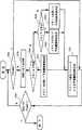
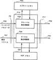
図1は実施の形態1及び後述する実施の形態における符号化装置の構成を示すブロック図である。同図において、1は入力動画像信号、2はテクスチャデータ、3は動き検出部、4は動きパラメータ、5は動き補償部、6は予測画像候補、7は予測モード選択部、8は予測モード、9は予測画像、10は予測誤差画像、11はテクスチャ符号化部、12は量子化DCT係数、13は局所復号された予測誤差画像、14は局所復号画像、15はメモリ更新部、16はメモリa、17はメモリb、18はメモリc、19は可変長符号化・多重化部、20は送信バッファ、21はビットストリーム、80はシーンチェンジ検出部、81はタイマーである。このうち動き補償部5およびメモリ更新部15が予測方式を実現する予測画像生成部100である。また、メモリa,b,cがメモリ領域200である。図中この実施の形態で取り上げない部分については後の実施の形態で説明する。図2は、この符号化装置の動作の流れを示すフローチャートである。
この実施の形態では複数、例えば3つのメモリ、を入力動画像の動き量・色度等の画像の特徴に基づく重要度に応じて使い分け、かつ任意の時間間隔で任意のメモリ(領域)、例えばメモリa、の内容を更新する仕組みを設ける。また、動画像シーケンスはフレーム単位に入力されるものとする。
(1)入力信号
上述のごとく、上記符号化装置は動画像シーケンスの各時刻の画像を表すフレームを単位に入力し、フレームは被予測画像領域の一例である符号化単位となるマクロブロックに分割される(ステップS1)。
(2)メモリの使い分け方
メモリには、過去に復号済みの画像や、またはあらかじめ固定的に与えられた画像が蓄積されるが、この実施の形態では、フレーム中の部分領域の重要度に応じて、3つのメモリを以下のように使い分ける。
メモリa:重要度小の画像領域(=動きが静止または均一で、かつテクスチャが均一な背景的画像領域)を蓄積する。
メモリb:重要度中の画像領域(=被写体の動きで、比較的動きの小さい画像領域)を蓄積する。
メモリc:重要度大の画像領域(=被写体の動きで、動きの大きな画像領域)を蓄積する。
メモリaに蓄積される重要度小の画像領域は、テレビ会議のシーンなどに出てくる背景画像領域と考えることができる。また、ある微少な動きを伴う被写体を含み、カメラ操作によって画面全体の均一な動きが含まれるようなシーンにおける背景領域にも相当する。これらの動きはマクロブロックという小さな単位よりもあらかじめフレーム全体の動きを求めて、それをマクロブロックの動きとして代用すると効率的である。すなわち、従来例に述べたスプライトにおけるワーピングパラメータに相当する変形パラメータを求め、フレーム全体の変形パラメータを各マクロブロックの動きパラメータとみなすことにする。動きパラメータは、単なる平行移動パラメータ(=動きベクトルと同義)でもよいし、変形を含んだアフィン、遠近法動きパラメータなどであってもよい。ここで、動きベクトルは動きパラメータの一例である。
メモリbに蓄積される重要度中の画像領域は例えばテレビ会議のシーンにおいて発言をせずに体だけが動いているような人物の画像領域で、画面中の注目度が低い被写体領域と考えることができる。メモリcに蓄積される重要度大の画像領域は例えばテレビ会議のシーン中、発言者などもっとも注目度が高い被写体領域と考えることができる。
メモリb、cに蓄積される領域は被写体固有の動きを持つため、マクロブロックごとに異なる動きパラメータを持つと考えるのが自然である。この際の動きパラメータは、単なる平行移動パラメータ(=動きベクトルと同義)でもよいし、変形を含んだアフィン、遠近法動きパラメータなどであってもよい。
(3)動き検出(ステップS2)
この実施の形態における動き検出部3は、従来例のような動きベクトルとワーピングパラメータという区別を取り去り、3つのメモリすべてについて任意の変形パラメータをマクロブロック単位に検出できるようにする。また、動き検出部3はメモリaを用いてフレーム全体の変形パラメータを検出するグローバル動きパラメータ検出と、メモリaからcを用いてマクロブロックごとの変形パラメータを検出するローカル動きパラメータ検出の機能を備える。
(4)動き補償(ステップS3)
この実施の形態における動き補償部5の内部構成を図3に示す。同図において、22は予測画像メモリアドレス算出部、23は予測画像メモリアドレス、24はメモリ読み出し部、25は外部から与えられる参照メモリ指示信号である。ここでは、参照メモリ指示信号25は、メモリa,b,cを使用することを指示しているものとする。この動き補償部5の動作を記したフローチャートを図4のステップS11からステップS16に示す。
まずI(Intra)-フレームならば、動き補償を行わない(ステップS11)。I-フレームでなければ、動き検出部3で検出されたグローバル動きパラメータならびに各メモリに基づくローカル動きパラメータをもとに予測画像候補を生成する(ステップS12からステップS15)。具体的には、予測画像メモリアドレス算出部22において、参照メモリ指示信号25で指示されるメモリ中の予測画像候補が存在する予測画像メモリアドレス23を動きパラメータ4に基づいて計算し、予測画像メモリアドレス23によってメモリ読み出し部24が対応するメモリから予測画像候補6を取り出して出力する。
この実施の形態においてはグローバル動きパラメータもローカル動きパラメータも同一の変形方式に基づくので、いずれの予測画像生成も図3の動き補償部5を共有して用いることができる。なお、グローバル動きパラメータにより予測画像候補6を生成する場合(ステップS15)は、常にメモリaが参照メモリとして用いられる。
(5)予測モードの選択(ステップS4)
この実施の形態における予測モードは、
(a)メモリaを使用するモード、
(b)メモリbを使用するモード、
(c)メモリcを使用するモード、
(d)イントラフレーム符号化信号を使用するモード
があるものとする。予測モード選択部7は、例えば従来例に示したように、動き補償部5によって生成されるすべての予測画像候補6とイントラフレーム符号化信号を含めて、最も予測誤差信号の電力(振幅)の小さい予測画像候補6を選択して予測画像9として出力する。また、選択した予測画像9に対応する予測モード8を出力する。この予測モード8の情報の中には、選択した予測画像9を予測したメモリを示すメモリ選択情報も含まれている。予測モード8は可変長符号化・多重化部19へ送られ、割り当てられた符号長で予測メモリ指示情報800としてビットストリーム21の中に符号化される。
(6)メモリの更新
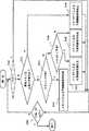
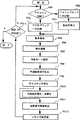
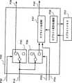
メモリの更新はメモリ更新部15で制御される。この実施の形態におけるメモリ更新部15の内部構成を図5に示す。同図において、26はメモリaの更新に用いるアクティビティ(詳細は後述する)、27はメモリa更新判定部、28は参照メモリ選択部、29、30はスイッチ、31はメモリaを更新する画像データ、32はメモリbを更新する画像データ、33はメモリcを更新する画像データ、34はメモリaを更新するグローバル予測画像データである。また、メモリ更新の動作フローを図6に示す。
この実施の形態におけるメモリ更新は以下の手順を踏む。メモリ更新部15は局所復号画像14を入力すると、メモリa更新判定部27において該局所復号画像14が属するフレームに対するメモリa更新の必要性を判定し(ステップS17)、参照メモリ選択部28において予測モード8に基づき予測に使用したメモリを選択し(ステップS18、S19)、選択されたメモリ内の参照画像を該局所復号画像14のメモリaを更新する画像データ31、メモリbを更新する画像データ32、メモリcを更新する画像データ33、メモリaを更新するグローバル予測画像データ34のいずれかを用いて下記のルールで更新する。なお、該メモリ更新は予測単位(マクロブロック単位)でフレーム毎に行われる。
(1)メモリb、cの毎フレーム更新(ステップS20、S21)
当該画像の予測に用いたメモリbまたはメモリcに、局所復号画像14を書き込む。
(2)メモリaの任意フレーム更新(ステップS22、S23)
当該画像の予測に用いたメモリaにステップS17のメモリa更新判定結果1000に基づき、任意のフレームについてのみ、または任意の時間間隔で局所復号画像14を書き込む。
メモリaの内容はいわば背景画像などの時不変画像領域の履歴であり、シーンチェンジや画面全体の大きな動きなどによって領域の内容がおおきく変化することでもない限り、メモリ内容の更新の必要がない。
上述のように被写体などの動領域についてはフレーム単位で逐次更新し、メモリaの内容はより長い時間間隔で更新する仕組みを備えておけば、被写体の動きによって見え隠れする背景画像などの予測に効果的である。
この実施の形態では、以上の観点からメモリaの更新を任意の時間間隔で行う仕組みを設ける。具体的には例えば、
a.グローバル動きパラメータの大きさに基づき、動きが大きい場合は画面全体の内容を一斉に更新し、動きが小さい場合は内容を更新しない方法、
b.フレーム間の時間間隔に限定されず、ある一定時間ごとに画面全体の内容を一斉に更新する方法、
c.シーンチェンジを検出した場合、シーンチェンジ直後のフレームで画面全体の内容を一斉に更新する方法
などの任意更新判定基準が考えられる。
この実施の形態では、以上のような任意更新判定基準になるデータをメモリaの更新に用いるアクティビティ26という言葉で総称する。まず、メモリa更新判定部27はアクティビティ26を用いてメモリaの内容を更新するかどうかを判定する(ステップS17)。上記任意更新判定基準aの場合は動き検出部3で検出されたグローバル動きパラメータの値がアクティビティとなり、任意更新判定基準bの場合はタイマー81からの当該フレームのタイムスタンプが、任意更新判定基準cの場合はシーンチェンジ検出部80から出力されるシーンチェンジ検出を知らせるフラグがアクティビティ26に相当する。
メモリaの内容を更新すると判断された場合は、局所復号画像14の内容がグローバル予測画像データ34として出力されてメモリaの内容を書きかえる(ステップS23)。メモリaの内容を更新すると判断されなかった場合は、メモリaの更新を行わない。
なお、当該フレームにおけるメモリa更新判定結果1000は復号側で同様の任意更新を行うことができるよう、ビットストリーム21に多重化されて復号側に伝送される。
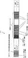
図20は、この実施の形態のビットストリーム21を示す図である。
図20においては、フレームデータが順に符号化されて転送される様子を概念的に示している。各フレームデータの先頭には、フレーム単位の付加情報としてヘッダ情報が付け加えられている。また、ヘッダ情報には、メモリa更新判定結果1000が多重化されて復号側に伝送される。ヘッダ情報の後からは、そのフレームを構成するマクロブロックデータが続いている。マクロブロックデータの内部には、そのマクロブロックデータを予測するために用いられたメモリを示す予測メモリ指示情報800が含まれている。復号装置においては、各マクロブロックデータの予測メモリ指示情報800に基づいて、予測画像を予測するメモリを特定して予測画像を生成する。
また、図示していないが、メモリa更新判定結果1000とともに、或いは、その代わりに、メモリb更新情報、及び/又はメモリc更新情報を復号側に転送するようにしても構わない。
以上述べた符号化装置により、動画像シーケンスの内容に応じて複数のメモリを効率的に使い分ける仕組みが供給され、予測効率を向上させることができる。すなわち、動画像シーケンスの予測に際して、動画像シーケンスの内容や性質によって複数のメモリを使い分けて任意の変形パラメータに基づいた予測を行うので、複雑な動きまでもカバーして局所的な画像の性質に追随した効率的な動画像予測が行え、予測効率が向上し、符号化画像の品質を保ちつつ符合化データの発生量を低減させる符号化装置を構成することができる。また、この発明の予測方式に基づいて符号化されたビットストリームを復号する復号装置においても同様の予測方式により構成することができる。
この実施の形態ではフレームごとに符号化する装置について述べたが、任意の形状を持つ動画像オブジェクト(VOP)を符号化する装置についても同様の効果が期待できる。
また、この実施の形態では被予測画像領域の一例としてマクロブロッキングを単位とした符号化装置について述べたが、任意の形状を持つ部分画像などの画像単位または複数個の固定サイズブロックの組み合わせによって構成される可変形状のブロックなどの画像単位で画像を符号化する装置についても、同様の効果が期待できる。
また、この実施の形態では、メモリaを用いたグローバル動きパラメータ検出を用いたが、これを用いずにローカル動き検出だけを用いる構成でも適用可能であることは言うまでもない。グローバル動き検出を行わない場合は、予測モードとしてグローバル/ローカル予測の判別情報は伝送する必要がない。
また、この実施の形態において、あらかじめ動画像シーケンスの内容に基づいて生成した参照画像データを蓄積して符号化中に更新を行わないメモリを設け、それを予測に用いる構成もとることができる。
また、この実施の形態においては、メモリa,b,cに対してそれぞれ部分領域を蓄積するようにしてメモリ更新部15によるメモリ更新は、メモリa,b,cのいずれか1つのメモリに対して行う場合を示したが、メモリa,b,cが画像の一部分、或いは、全部を共有して画像を蓄積するような場合には、メモリ更新部15は、メモリa,b,cのうち2つのメモリ、或いは、全てのメモリを更新する。例えば、メモリaが1フレームの参照画像データを蓄積するフレームメモリであり、メモリbが逐次更新を伴わないスタティックスプライトメモリであり、メモリcが逐次更新を伴うダイナミックスプライトメモリである場合には、スタティックスプライトメモリは、予め固定的なデータを参照画像データとして蓄積しているため、メモリbはメモリ更新部15によっては更新されないが、メモリaとメモリcが同一領域の参照画像データを蓄積している場合には、メモリ更新部15は、メモリaとメモリcを同時に更新することになる。このように、メモリa,b,cが参照画像データを重複して蓄積している場合には、重複した領域をそれぞれメモリ更新部15が更新する。
以上のことは、以下に述べる実施の形態においても同様である。
また、この実施の形態では、3つのメモリa,b,cを用いる場合を示したが、いずれか2つのメモリを用いる場合であっても構わない。
また、この実施の形態で述べた動き補償部5、メモリ更新部15とまったく同一の部材を有する予測画像生成部100を用いた復号装置を構成することもできる。復号装置に用いられる場合は、動き補償部は3つの全ての予測画像候補を生成する必要はなく復号された動きパラメータに関わる予測画像だけを生成すればよい。
実施の形態2.
次に、図1に示した構成の符号化装置において、動き補償部5の構成だけ別の構成とした符号化装置の実施形態を示し、実施の形態2の動き補償部5aの構成と動作について述べる。
この実施の形態における動き補償部5aの内部構成を図7に示す。同図において、35は参照メモリ決定部である。またこの動き補償部5aの詳細な動作を記したフローチャートを図8に示す。
まず、I-フレームならば動き補償を行わない(ステップS24)。I-フレームでなければ、参照メモリ決定部35は動きパラメータ4の値に基づいて参照メモリを決定する(ステップS25)。参照メモリ決定部35は各メモリa,b,cに割り当てられている有効動きパラメータ値域(詳細は後述する)を保持しており、動きパラメータ4の値と比較することによって、当該動きパラメータ4がどのメモリを指しているかを判断し、メモリa,b,cを識別する参照メモリ指示信号25aを出力する。
有効動きパラメータ値域とは、例えば動きベクトルを検出する場合、その探索範囲が±15画素だとすると、±0から3画素の範囲ではメモリaを、±4から8画素の範囲ではメモリbを、±9から15画素の範囲ではメモリcを予測に用いるようにするというような、各メモリごとの有効探索範囲を意味する。ただし、グローバル動きパラメータで予測画像を生成する場合は参照メモリはメモリaと決まっているので、参照メモリ決定部35を起動するのはローカル動きパラメータを用いるときのみとする。このように、動きベクトルの値で予測に用いるメモリを特定するのは、背景画像は動きが少なく、注目度が高い画像ほど動きが大きくなるはずであるという前提に基づくものである。このように、動きベクトルの値で予測に用いるメモリを特定する場合は、予測モードを符号化して伝送する必要がない。
次いで、選択された参照メモリ指示信号25aにしたがって予測画像候補6が生成される(ステップS26からステップS30)。具体的には、予測画像メモリアドレス算出部22において、参照メモリ指示信号25aで指示されるメモリ中の予測画像候補6が存在する予測画像メモリアドレス23を動きパラメータ4に基づいて計算し、予測画像メモリアドレス23によってメモリ読み出し部24が対応するメモリから予測画像候補6を取り出して出力する。
この実施の形態においてはグローバル動きパラメータもローカル動きパラメータも同一の変形方式に基づくので、いずれの予測画像生成も図7の動き補償部5aを共有して用いることができる。なお、グローバル動きパラメータにより予測画像候補6を取り出す場合(ステップS31)は、常にメモリaが参照メモリとして用いられる。
有効動きパラメータ値域は、動画像シーケンス毎に一定地域でもよいが、たとえば、各フレーム毎に変更してもよい。各フレーム毎に変更する場合は、当該フレームにおける各メモリの有効動きパラメータ値域は、復号側で同様のメモリ選択を行うことができるよう、ビットストリームに多重化されて復号側に伝送される。
図21は、この実施の形態のビットストリーム21を示す図である。
このビットストリームの先頭には、動画像シーケンス単位に付加されたヘッダ情報がある。このヘッダ情報は、各メモリの有効動きパラメータ値域指示情報を有している。このように、動画像シーケンスの先頭に有効動きパラメータ値域指示情報を指定することにより、その動画像シーケンスに対して一定値域の有効動きパラメータ値域を用いた予測方式を復号装置で行うことができる。
フレーム毎に有効動きパラメータ値域を変更する場合は、フレーム単位に付加されたヘッダ情報の中の有効動きパラメータ指示情報を含ませればよい。
以上述べた動き補償部5aの構成を持つ符号化装置により、フレームの局所的な動きの程度に応じて複数のメモリを効率的に使い分ける仕組みが供給され、予測効率を向上させることができる。
この実施の形態ではフレームごとに符号化する装置について述べたが、任意の形状を持つ動画像オブジェクト(VOP)を符号化する装置についても同様の効果が期待できる。
また、この実施の形態ではマクロブロックを単位とした符号化装置について述べたが、任意の形状を持つ部分画像などの画像単位または複数個の固定サイズブロックの組み合わせによって構成される可変形状のブロックなどの画像単位で画像を符号化する装置についても、同様の効果が期待できる。
また、この実施の形態では、メモリaを用いたグローバル動きパラメータ検出を用いたが、これを用いずにローカル動き検出だけを用いる構成でも適用可能であることは言うまでもない。グローバル動き検出を行わない場合は、予測モードとしてグローバル/ローカル予測の判別情報は伝送する必要がない。
また、この実施の形態で述べた動き補償部5とまったく同一の部材有する予測画像生成部100を用いた復号装置を構成することもできる。復号装置に用いられる場合は、動き補償部は復号された動きパラメータに関わる予測画像だけを生成すればよい。
実施の形態3.
次に、図1に示した構成の符号化装置において、動き補償部5の構成だけをさらに別の構成とした符号化装置の実施形態を示し、動き補償部5bの構成と動作について述べる。この実施の形態における動き検出部3aは、動きパラメータ4aとして平行移動量、アフィンパラメータ、遠近法パラメータをそれぞれ出力するものとする。
また、この実施の形態におけるメモリaは参照画像を1フレーム分記憶するフレームメモリであり、メモリbはスタティックスプライトメモリであり、メモリcはダイナミックスプライトメモリであるものとする。
この実施の形態における動き補償部5bの内部構成を図9に示す。同図において、36は平行移動量(=動きベクトル)、37はアフィンパラメータ、38は遠近法パラメータ、39は平行移動量に基づく予測画像メモリアドレス算出部、40はアフィンパラメータに基づく予測画像メモリアドレス算出部、41は遠近法パラメータに基づく予測画像メモリアドレス算出部である。またこの動き補償部5bの詳細な動作を記したフローチャートを図10に示す。
まず、I-フレームならば動き補償を行わない(ステップS33)。I-フレームでない場合、予測画像メモリアドレス算出部39から41はそれぞれ動きパラメータ4aの値に基づいて予測画像メモリアドレス23を計算する(ステップS34)。
各予測画像メモリアドレス算出部は、対応する各メモリに割り当てられている画像変形方式に基づいてアドレス計算を行う。この実施の形態においては、メモリaに平行移動、メモリbにある程度回転や拡大・縮小などの単純な変形を伴うアフィンパラメータ、メモリcに3次元的で複雑な動きを伴う遠近法パラメータを用いる。これらの変形方式は以下のような変換式で表せる。
〔平行移動〕
平行移動量(a,b):
x'=x+a
y'=y+b
〔アフィン変換〕
アフィンパラメータ(a,b,c,θ):
x'=a(cosθ)x+a(sinθ)y+b
y'=a(-sinθ)x+a(cosθ)y+c
〔遠近法変換〕
遠近法パラメータ(a,b,c,d,e,f):
x'=(a x+b y+c)/(g x+h y+1)
y'=(d x+e y+f)/(g x+h y+1)
ここで、2次元座標上の(x, y)は原マクロブロックの画素位置、(x',y')は各パラメータによって(x, y)に対応付けられるメモリ中の画素位置である。すなわち、これらのパラメータをもとに(x', y')のメモリ上に位置を計算する。この仕組みをもつことにより、各マクロブロックごとに動きの性質がもっとも適合するメモリから予測を行うことができるようになる。各動きパラメータ36、37、38から計算した予測画像メモリアドレス23によって、メモリ読み出し部24が対応するメモリから予測画像候補6を取り出して出力する(ステップS35からステップS39)。
なお、当該フレームにおける各メモリの変形方式のタイプは、復号側で同様の動き補償を行うことができるよう、動き検出手法指示情報としてビットストリーム21に多重化されて復号側に伝送される。
図22は、この実施の形態のビットストリーム21を示す図である。
動画像シーケンスの先頭に付加されるヘッダ情報の中には、動き検出手法指示情報が含まれている。符号化装置では、各メモリで使用する変形方式のタイプが変更可能であり、この対応関係を示す動き検出手法指示情報を動画像シーケンスのヘッダ情報として復号装置に送る。こうして復号装置においては、各メモリで使用する変形方式のタイプを識別することができる。
復号装置においては、この識別された変形方式のタイプが動的に各メモリに対応づけられるようになっている。
以上述べた動き補償部5bの構成を持つ符号化装置により、フレームの局所的な動きの性質に応じて複数のメモリを効率的に使い分ける仕組みが供給され、予測効率を向上させることができる。
この実施の形態ではフレームごとに符号化する装置について述べたが、任意の形状を持つ動画像オブジェクト(VOP)を符号化する装置についても同様の効果が期待できる。
また、この実施の形態ではマクロブロックを単位とした符号化装置について述べたが、任意の形状を持つ部分画像などの画像単位または複数個の固定サイズブロックの組み合わせによって構成される可変形状のブロックなどの画像単位で画像を符号化する装置についても、同様の効果が期待できる。
また、この実施の形態では、メモリaを用いたグローバル動きパラメータ検出を用いたが、これを用いずにローカル動き検出だけを用いる構成でも適用可能であることは言うまでもない。グローバル動き検出を行わない場合は、予測モードとしてグローバル/ローカル予測の判別情報は伝送する必要がない。
また、この実施の形態では、メモリa,b,cを用いる場合を示したが、メモリaとbだけを用いる場合、或いは、メモリaとcを用いる場合、或いは、メモリbとcだけを用いる場合であっても構わない。
また、この実施の形態で述べた動き補償部5bとまったく同一の部材を有する予測画像生成部100を用いた復号装置を構成することもできる。復号装置に用いられる場合は、動き補償部は復号された動きパラメータに関わる予測画像だけを生成すればよい。
実施の形態4.
次に、形状情報を持った複数、例えば2つ、の異なる動画像オブジェクトが混在する動画像シーケンスを対象とし、これらの動画像オブジェクトを一括して符号化する装置の実施形態を説明する。図11にこの実施の形態における符号化装置の構成を示す。
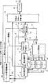
同図において、42は入力画像フレーム、43はオブジェクト分離部、44a、44bはオブジェクトデータ、45a、45bは形状ブロック、46a、46bはスイッチ、47a、47bは形状符号化部、48a、48bは圧縮形状ブロックデータ、49a、49bは局所復号形状ブロック、50a、50bはテクスチャデータ(マクロブロック)、51a、51bは動き検出部、52a、52bは動きパラメータ、53a、53bは動き補償部、54a、54bは予測画像候補、55a、55bは予測モード選択部、56a、56bは予測モード情報、57a、57bは予測画像、58a、58bは予測誤差信号、59a、59bはテクスチャ符号化部、60a、60bは圧縮テクスチャデータ、61a、61bは局所復号予測誤差信号、62a、62bは局所復号マクロブロック、63はメモリ更新部、64はメモリa、65はメモリb、66はメモリc、67はメモリd、68はメモリe、69はメモリf、70a、70bは可変長符号化部、71は多重化部、72はバッファ、73はビットストリーム、94はメモリ部、88aはAオブジェクトを符号化するAオブジェクト符号化部、88bはBオブジェクトを符号化するBオブジェクト符号化部である。オブジェクト符号化部88a、88bは同一の部材による同一の内部構成を有する。
この符号化装置は画像フレーム42を入力し、これがオブジェクト分離部43において符号化単位のオブジェクトに分けられる。オブジェクト分離部43の処理は任意の方法をとることができるものとする。
オブジェクトの形状情報は形状ブロック45a、45bの形式で形状符号化部47a、47bに送られて符号化され、圧縮形状ブロックデータ48a、48bとして可変長符号化部70a、70bに送られる。
動き検出部51a、51bはVM符号化方式と同様、局所復号形状ブロック49a、49bを考慮して動きパラメータの検出を行う。動きパラメータ検出はマクロブロック単位にメモリaからfのすべてを用いて行うことができる。
ただし、原則としてAオブジェクト符号化部88aにおいて符号化されるAオブジェクトについてはメモリaからcを、Bオブジェクト符号化部88bにおいて符号化されるBオブジェクトについてはメモリdからfをそれぞれ用いるものとする。
また、動きの種類としては、動きベクトルとワーピングパラメータという区別を取り去り、メモリ部94のすべてのメモリについて任意の変形パラメータをマクロブロック単位に検出できるものとする。
動き補償部53a、53bで各動きパラメータ52a、52bに基づいてすべての予測画像候補54a、54bを生成した後、予測モード選択部55a、55bで予測画像57a、57bおよび予測モード情報56a、56bを得る。原信号またはテクスチャデータ50a、50bと予測画像57a、57bとの差分をとって予測誤差信号58a、58bを得、これがテクスチャ符号化部59a、59bで符号化されて可変長符号化部70a、70bに送られる。また、局所復号された予測誤差信号61a、61bが予測画像57a、57bと加算されて局所復号マクロブロック62a、62bとなり、メモリ更新部の指示にしたがってメモリaからfに書き込まれる。
上記A/Bオブジェクト符号化部88a、88bにおいて符号化されたA/Bオブジェクトデータは多重化部71で1つのビットストリーム73に多重化され、バッファ72を介して伝送される。
以下、この実施の形態における予測について主要な動作を行う動き補償部53a、53bを中心に説明する。
この実施の形態における動き補償部53a、53bは、動き検出部51a、51bで検出した動きパラメータ52a、52bに基づいて予測画像候補を生成する。動き補償部53aの内部構成を図12に示す。また、Aオブジェクト符号化部88aにおける動き補償部53aの動作のフローチャートを図13に示す。なお、動き補償部53bでも同様に構成され同様に動作する。
図12において、74aはBオブジェクト参照判定部、75aはBオブジェクト参照指示フラグである。
ここで動きパラメータ52aは検出に用いたメモリ情報も含むものとする。パラメータの値から実施の形態1と同様に、予測画像メモリアドレス算出部22a、メモリ読み出し部24aを用いて予測画像候補を生成する(ステップS44からステップS49)。また、Bオブジェクト参照判定部74aは動きパラメータ52aの中の参照するメモリ情報から、当該マクロブロックの予測にBオブジェクト用のメモリを使用しているかどうかを判定する(ステップS43)。
Bオブジェクト参照判定部74aは、判定結果をBオブジェクト参照指示フラグ75aとして出力し、復号側で当該オブジェクトが単独で、自身のメモリa,b,cのみを用いて再生できるかどうかの判定に用いるため、ビットストリーム73に多重化されて復号側に伝送される。符号化時には、外部から与える信号85aにより、常に復号側で当該オブジェクトの単独再生が可能になるように、動きパラメータの検出に際して、自身の予測用のメモリ(a,b,c,のみ)しか使用しないように制御することも可能とする。
以上述べた動き補償部53a、53bの構成を持つ符号化装置により、フレームの局所的な動きの性質に応じて複数のメモリを効率的に使い分ける仕組みが供給され、予測効率を向上させることができる。
また、この実施の形態ではオブジェクトをマクロブロック単位に符号化する装置について述べたが、任意の形状を持つ部分画像または複数個の固定サイズブロックの組み合わせによって構成される可変形状のブロックなどの単位で符号化する装置についても、同様の効果が期待できる。
また、この実施の形態で述べた動き補償部53a、53bと同一の部材を用いた復号装置を構成することもできる。復号装置に用いられる場合は、動き補償部53は復号された動きパラメータに関わる予測画像だけを生成すればよい。また、ビットストリームから他オブジェクト参照指示フラグ75a、75b相当のビットを復号して、復号中のオブジェクトが単独で再生できるかどうかを認識できる構成とすれば、オブジェクトデータを誤りなく復号再生できるようになる。
実施の形態5.
次に、動画像オブジェクトの時間的変化に対応して、メモリの数または容量を自在に変化可能な構成の符号化装置の実施形態を説明する。実施の形態5においては、図1に示した構成の符号化装置におけるメモリ更新部15の構成を置きかえた符号化装置を考える。
図14にこの実施の形態におけるメモリ更新部15aの内部構成を示す。同図において、76はメモリ拡張判定部、77はメモリ拡張指示信号、78はメモリ縮退判定部、79はメモリ縮退指示信号である。図15はメモリ更新部15aの動作フロー(ステップS51からステップS63)を示す。
シーンチェンジなどによりメモリに蓄積されていた動画像シーケンスの履歴とは著しく異なる画像が現れた場合、シーンチェンジ後の予測においては、既存メモリに含まれる参照画像だけでは予測効率が劣化することがある。そのような場合、シーンチェンジ検出部80によりシーンチェンジを検出し、シーンチェンジ直後のフレームはイントラフレーム符号化するなどして、それを新たな参照画像としてメモリに追加蓄積しておくことができれば、それ以降の予測効率を向上できる。
また、追加できるメモリの容量には物理的限界があるため、メモリ上の参照画像のうち、ほとんど予測に使われない部分を逐次縮退できる仕組みも持たせる。メモリa,b,cの各メモリ領域予測に使われる頻度を予測モード8に基づいてメモリ更新部15aで計測しておき、メモリ更新部に頻度の小さいメモリ領域を使用領域から開放する仕組みをもたせる。この実施の形態によれば、例えばソフトウエアで符号化装置を構成するような場合、限られたRAM(ランダムアクセスメモリ)資源を有効に活用することができる。
以上の観点から、この実施の形態におけるメモリ更新部15aは、動画像シーケンスの時間的変化の状況に応じてメモリ領域を増やしたり、予測にあまり使われない参照画像を含むメモリ領域を縮退したりする機能を備える。
メモリaについては、実施の形態1と同様、メモリa更新判定部27において更新の可否が決定され(ステップS50)、更新する場合は局所復号画像14をメモリaに書き込む(ステップS56、ステップS57)。また、予測モード8にしたがって各メモリへ局所復号画像14が書き込まれる(ステップS51からステップS55)。
これらメモリ内容更新は、メモリ拡張/縮退の判定をともなって行われる。メモリ拡張判定部76においては、メモリaの更新に用いるアクティビティ26をもとにメモリa(またはメモリb,c)の容量を増やすかを判定する(ステップS58からステップS60)。シーンチェンジなどにより容量を増やした方がよいと判定されれば、メモリ拡張指示信号77によってメモリの拡張が指示される。また、メモリ縮退判定部78においては、予測モード8をもとに予測に用いられるメモリ領域のカウントをおこなっておき、所定の回数以下しか予測に用いられないメモリ領域については、メモリ縮退指示信号79によってメモリの縮退が指示される(ステップS61からステップS63)。
以上述べたメモリ更新部15aの構成を持つ符号化装置により、動画像シーケンスの時間的変化に追随して効率のよい予測が行えるとともに、予測に必要なメモリ領域をダイナミックに割り当てる仕組みが供給され、予測効率を向上させるとともにメモリ資源の有効活用が可能になる。
この実施の形態ではフレームごとに符号化する装置について述べたが、任意の形状を持つ動画像オブジェクト(VOP)を符号化する装置についても同様の効果が期待できる。
また、この実施の形態ではフレームをマクロブロック単位に符号化する装置について述べたが、任意の形状を持つ部分画像などの画像単位または複数個の固定サイズブロックの組み合わせによって構成される可変形状のブロック領域などの画像単位で画像を符号化する装置についても、同様の効果が期待できる。
また、この実施の形態で述べたメモリ更新部15aとまったく同一の部材を用いた復号装置を構成することもできる。
実施の形態6.
上記の各実施の形態においてはマクロブロックで予測に使用するメモリを変更する場合を示したが、フレームもしくは動画像オブジェクトの単位で、予測に使用するメモリを変更して予測を行う構成をとることもできる。これにより、フレームもしくは動画像オブジェクトの単位で符号化すべきメモリ関連の情報、およびマクロブロック単位で符号化すべきメモリ選択情報(予測モード8に含まれる)を符号化する必要がなくなり、効率的な符号化を行うことができる。
例えば実施の形態1における図1の符号化装置においては、マクロブロック単位で予測に使用するメモリを切替えることが可能になっているため、マクロブロック単位でどのメモリを予測に使用したかを示す付加情報を伝送する必要がある。これに対して、本実施の形態ではこの使用メモリの切替の単位をフレームまたは動画像オブジェクトに制限して予測を行うことにより、マクロブロック単位に伝送すべき付加情報を効果的に削減することを可能とする。図23は、図20に示した実施の形態1の伝送ビットストリーム21と本実施の形態の伝送ビットストリーム21との違いを示す。図23に示す例は、フレーム単位に予測に使用するメモリを変更する場合を示しており、予測メモリ指示情報800がフレーム単位のヘッダ情報に含まれている。図23に示す例は、例えば、動画像シーケンスの映像の性質が定常的に変化せず、マクロブロックレベルの局所的な変化が少ないような場合に有効である。また、以上のようにして符号化されたビットストリームを復号してフレームもしくは動画像オブジェクトを再生する復号装置を構成することもできる。
実施の形態7.
上記の各実施の形態において、複数のメモリのうち、任意の複数、例えば2つ、のメモリ(例えばメモリaとb)から取り出された2つの予測画像候補を加算平均した画像を予測画像候補6の1つとする構成または予測画像9として用いる構成にすることができる。また、以上のようにして符号化されたビットストリームを復号してフレームもしくは動画像オブジェクトを再生する復号装置を構成することもできる。
実施の形態8.
上記の各実施の形態に示した符号化装置において、予測を行う単位となる画像領域の空間的な複雑さ、注視度、などを規定する特徴量パラメータをあらかじめ検出しておき、これらを予測モード決定、メモリ更新の際の判定尺度として利用する構成をとることができる。
例えば、複雑な動きを含み、与えられた符号量内で許容品質を達成する符号化を行うことが困難な動画像を想定する。このような場合は、被予測画像領域(マクロブロック、任意形状画像領域、任意形状ブロックなど)ごとに重要度を見極め、重要度の低い領域はある程度品質を落して符号量を減少させ、その分を重要度の高い領域に割り当てて全体の品質を向上させる。本発明のように複数のメモリを任意のタイミングで切り替えて予測を行う装置では、被予測画像領域の重要度を表す特徴量パラメータを検出して、これに基づいて動的にメモリ使用方法を決定することにより、より画像の性質に適応した予測を行うことができる。例えば、図16に示すように、領域ごとに特徴量パラメータを検出して重要度を決定する領域重要度検出部95を設ける。領域重要度検出部95は領域重要度を予測モード選択部7aへ伝えるとともに領域重要度に基づく量子化パラメータをテクスチャ符号化部11aへ伝える。領域重要度検出部95で重要度が高いと判定された領域は、複数用意された予測モードのうち、もっとも複雑なモードを用いて予測を行う。例えば、各メモリa,b,cからの参照画像を用いてそれぞれ複雑な動きモデルに基づいた動きパラメータと予測画像を求め、これら予測画像の任意の組み合せ(加算平均など)も含めて最も予測効率の高い予測モードを予測モード選択部7aにおいて選択する。この際、予測に使用したすべてのメモリに対して参照画像を更新する。さらに、テクスチャ符号化部11aでは、量子化ステップ幅が細かい量子化パラメータにより符号化を行う。一方、重要度の低い領域では、簡易な予測モード(1つのメモリだけを用いた平行移動量検出)によって予測を行い、得られた予測誤差信号の振幅に関わらず少ない符号量になるように、量子化ステップの粗い量子化パラメータを用いて符号化する。以上の制御を行うことによって、重要度の低い領域はある程度品質を落しても、重要度の高い領域は高度な予測によって品質が保たれ、与えられた符号量で全体の品質を向上することができる。
実施の形態9.
複数のメモリを用いて動画像シーケンスを予測、符号化する装置において、動画像シーケンスの各時刻において使用可能な符号量、あるいは当該時刻でのシーンの変化量(シーンチェンジ検出など)、実施の形態8で述べたような被予測画像領域の特徴量や重要度などのパラメータを検出しておき、これらの値を、当該時刻における画像の予測に用いることのできる予測方式、あるいは参照メモリ領域の選択の際の判定尺度として利用する構成をとることができる。例えば、図17のように、フレーム単位で重要度を決定するフレーム重要度検出部96を設け、前フレームに対する当該フレームの変化量(シーンチェンジ検出部80からのシンーンチェンジを検出)、新しいオブジェクトの出現・隠蔽の有無などを検出し、送信バッファ20から通知される当該フレームで使用できる符号量を考慮して最終的なフレーム重要度を決定する。これに基づいて、重要度の高いフレームでは用意されたすべての予測方式と参照メモリ領域を用いて最大限予測効率を向上し、重要度の低いフレームでは予測方式や参照メモリ領域を限定して用い、符号化処理を簡素化して処理量を低減する、という装置構成が考えられる。また、シーンチェンジ時に予測を行わずにすべてイントラフレーム符号化する装置も考えられる。さらに、実施の形態8で述べた領域重要度検出部95と併用すれば、よりきめ細かい品質制御を行うことができる。以上の制御を行うことによって、重要度の低いフレームはある程度品質を落しても、重要度の高いフレームは高度な予測によって品質が保たれ、与えられた符号量で全体の品質を向上することができる。
本実施の形態の考え方は、処理プロセスや使用可能なメモリ量が流動的なソフトウエアによる符号化の際に、利用できる資源を最大限に活用して効率よく符号化処理を行わせる場合にも適用可能である。重要度の低いフレームでは処理量を低減でき、全体の処理速度を向上させることができる。
実施の形態10.
図11に示したような、複数のメモリを用いて複数の動画像オブジェクトから構成される動画像シーケンスを予測、符号化する装置において、シーケンスとして使用できる総符号量、各動画像オブジェクトの各時刻において使用可能な符号量、あるいは当該時刻での動画像オブジェクトの変化量(オブジェクトの出現、隠蔽など)、各動画像オブジェクトのシーンの中での重要度/注視度のレベル、実施の形態8や9で述べたような被予測画像領域の特徴量や重要度などのパラメータを検出しておき、これらの値を、当該時刻における動画像オブジェクトの予測に用いることのできる予測方式、あるいは参照メモリ領域の選択の際の判定尺度として利用する構成をとることができる。
例えば、図18のように、各オブジェクト1〜nに対応する重要度検出部97a〜97nを設け、オブジェクトの各時刻における変化量やオブジェクトの出現・隠蔽の有無などを表すパラメータを検出するとともに、すべてのオブジェクトの符号化データが蓄積される全体バッファ72xの占有率、各オブジェクトの仮想バッファ72a〜72nの占有率とを考慮して、各時刻においてオブジェクトの重要度を決定する。例えば、オブジェクト内に他のオブジェクトの一部が重なるなどの結果として新しいタイプの領域が出現した場合、これは以降の予測効率に大きく影響するため、ある程度オブジェクトの仮想バッファに余裕のない場合であっても重要度を高くし、符号化画像をきれいにしておく、などの制御が考えられる。重要度検出部97a〜97nで検出された重要度はオブジェクト1〜N符号化部98a〜98nに渡され、重要度の高いオブジェクトでは用意されたすべての予測方式と参照メモリ領域を用いて最大限予測効率を向上し、重要度の低いオブジェクトでは予測方式や参照メモリ領域を限定して用い、符号化処理を簡素化して処理量を低減する、という装置構成が考えられる。また、フレームからリアルタイムにオブジェクト分離を行って符号化する装置では、新しいオブジェクトの出現や、既存オブジェクトの隠蔽などによって当該オブジェクトの内容が著しく変化した場合に、予測を行わずにすべてイントラフレーム符号化する装置も考えられる。さらに、オブジェクト1〜N符号化部98a〜98nにおいて実施の形態8で述べた領域重要度検出部95も併用すれば、オブジェクト内の各被予測対象領域単位によりきめ細かい品質制御を行うことができる。以上の制御を行うことによって、重要度の低いオブジェクトはある程度品質を落しても、重要度の高いオブジェクトは高度な予測によって品質が保たれ、与えられた符号量で全体の品質を向上することができる。
実施の形態11.
また、図19に示すように、予測に関する符号化情報(参照メモリ番号など)の符号割り当て(符号化)を行う予測情報符号化部91を設ける場合がある。
複数のメモリa,b,cを用いて動画像シーケンスまたは動画像オブジェクトを予測、符号化する装置において、予測に用いられるメモリの使用頻度に応じて複数のメモリのランク付けを行い、かつこのランク付けを符号化中にダイナミックに変更することができるようにして、上記予測情報符号化部91における予測に関する符号化情報(参照メモリ番号など)の符号割り当てを、予測に用いる複数のメモリのランクに応じて行うようにする構成をとることができる。
例えば、図19の符号化装置において、メモリ更新部15bに、メモリa,b,cそれぞれの予測に用いられる頻度をカウントするカウンタ92を設けておき、そのカウント値にしたがってメモリa,b,cをランク付けし、ランク情報90を出力する。このランク付けは、例えば1フレームもしくは動画像オブジェクトのある時刻における画像(VOP)を単位に行ってもよいし、より細かい単位である被予測画像領域(マクロブロック、任意形状領域、任意形状ブロックなど)毎に行うこともできる。
これにより、どのメモリがどれだけ頻繁に予測に使われるかを認識できる。頻繁に予測に用いられるメモリは、予測を行うにあたって重要度の高いメモリであり、参照頻度が高いほどランクを高くする。
このようにして、各被予測画像領域単位に予測に用いたメモリの頻度情報を符号化する場合、頻繁に参照するメモリ(=ランクが高いメモリ)には短い符号長を割り当てるほうが符号化効率が高まる。
また、各被予測画像領域単位に検出した動きパラメータも、参照したメモリのランクに対応して符号長を割り当てることができれば、頻繁に発生する動きパラメータ値に対して短い符号長を割り当てることができ、効率的な予測情報の符号化が可能になる。これらの仕組みは、可変長符号化・多重化部19の予測情報符号化部91がメモリ更新部15bのカウンタ92から各メモリのランクを受け取るようにしておき、このランク情報90に基づいて符号長を可変にして予測情報の符号化を行う構成で実現できる。
実施の形態12.
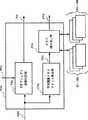
図24は、本実施の形態における、圧縮符号化されたディジタル画像を伸長再生する画像復号装置の構成を示したものである。同図において21は符号化されたビットストリーム、119は可変長復号部、12は量子化DCT係数、12aは量子化直交変換係数、12bは量子化ステップ、111はテクスチャ復号部、111aは逆量子化部、111bは逆直交変換部、190は復号加算部、101は復号画像、191は表示制御部、8は予測モード、1001はメモリb更新情報、1002はメモリc更新情報、4は動きベクトル(動きパラメータ)、800は予測メモリ指示情報、195は被予測画像領域の画面内位置、105は動き補償部、116はメモリa、117はメモリb、118はメモリc、115はメモリ更新部、106は予測画像である。動き補償部105とメモリ更新部115により予測画像生成部100aを構成している。また、メモリa,b,cによりメモリ領域200aを構成している。
この実施の形態では、メモリaは1フレーム分の画像データを蓄積するフレームメモリであり、メモリbはスタティックスプライトメモリであり、メモリcはダイナミックスプライトメモリであるものとする。また、この実施の形態の復号装置は、図22に示したビットストリーム21を入力するものとする。また、図22には示していないが、メモリb更新情報1001及びメモリc更新情報1002がビットストリームの中で送られてくるものとする。メモリb更新情報1001には、スタティックスプライトメモリを全面更新するための更新指示と全面更新するための画像データが含まれているものとする。同様に、メモリc更新情報1002には、ダイナミックスプライトメモリを全面更新する更新指示と全面更新するための画像データが含まれているものとする。
以下、上記構成の装置の動作を説明する。まず、可変長復号部119においてビットストリーム21が解析され、個々の符号化データに切り分けられる。量子化直交変換係数12aは逆量子化部119aに送られ、量子化ステップ12bを用いて逆量子化される。この結果が逆直交変換部111bにおいて逆直交変換されテクスチャが復号され、復号加算部190に送られる。直交変換はDCT(離散コサイン変換)など、符号化装置側で用いるものと同じものを用いる。
動き補償部105には、可変長復号部119でビットストリーム21から復号された動きベクトル4、予測メモリ指示情報800と、被予測画像領域の画面内位置195を示す情報が入力される。動き補償部105は、これらの3種類の情報にしたがって複数のメモリa,b,cに格納されている参照画像から所望の予測画像を取り出す。被予測画像領域の画面内位置195はビットストリームに含まれている情報ではなくマクロブロックの数をカウントすることにより計算できる。予測画像生成の処理については以下の動き補償部105の動作説明の箇所で詳述する。
復号加算部190は、予測モード8の情報に基づいて、イントラフレーム符号化されたブロックならば逆直交変換部111bの出力をそのまま復号画像101として出力し、インターフレーム符号化されたブロックなら逆直交変換部111bの出力に予測画像106を加算して復号画像101として出力する。復号画像101は表示制御部191に送られ、表示デバイスに出力されるともに、以降の復号処理において参照画像として用いるためにメモリa〜cに書き込まれる。メモリへの書き込みは予測モード8に基づいて、メモリ更新部115で制御される。
次に、予測画像生成部100aの動き補償部105における予測画像生成処理について説明する。本実施の形態では、画像の予測方式は予測メモリ指示情報800に基づいて決定される。本実施の形態による復号装置では、予測画像を生成するにあたって、動きベクトル4と予測メモリ指示情報800とに基づいて、所定の座標変換処理および内挿処理により参照画像から予測画像を生成する。座標変換処理の方法はあらかじめ予測に使用するメモリに対応づけられているものとする。例えば、実施の形態3で述べた画像変形方式と同じ以下のような変形手法の例を考えることができる。
(1)メモリaを予測に用いる場合(=予測メモリ指示情報800がメモリaの使用を指示している場合)
動きベクトルによって被予測対象領域の各画素の座標を平行移動させ、メモリa中の対応する位置の画像データを予測画像として取り出す。
(2)メモリbを予測に用いる場合(=予測メモリ指示情報がメモリbの使用を指示している場合)
動きベクトルに基づいてアフィン変換式を求め、同変換式によって被予測対象領域の各画素の座標を変位させ、メモリc中の対応する位置の画像データを予測画像として取り出す。
(3)メモリcを予測に用いる場合(=使用メモリ指示情報がメモリcの使用を指示している場合)
動きベクトルに基づいて遠近法変換式を求め、同変換式によって被予測対象領域の各画素の座標を変位させ、メモリb中の対応する位置の画像データを予測画像として取り出す。
動き補償部105の内部構成を図25に示す。同図において、161はスイッチ、162はメモリa用対応点決定部、163はメモリb用対応点決定部、164はメモリc用対応点決定部、165はメモリ読み出しアドレス生成部、166はスイッチ、167は内挿処理部である。また、図26はその動作の様子を示すフローチャートである。
以下、図25および図26をもとに、本実施形態における動き補償部105の動作を説明する。
1)対応点の決定
まず、予測メモリ指示情報800に基づき、スイッチ161によって対応するメモリ用の対応点決定部を選択し、選択された対応点決定部に動きベクトル4を入力する。ここでは、各メモリに対応した予測画像位置の算出を行う。以下、メモリ対応で説明する。
1ー1)予測メモリ指示情報800がメモリaを指示している場合(ステップS100)
動きベクトルによる平行移動によって、予測画像位置を算出する(ステップS101)。具体的には、動きベクトル(a,b)によって、被予測画像領域の位置(x,y)の画素に対する予測画像位置(x',y')を下式によって決定する。
x'=x+a
y'=y+b
決定された予測画像位置をメモリ読み出しアドレス生成部165に出力する。
1ー2)予測メモリ指示情報800がメモリbを指示している場合(ステップS103)
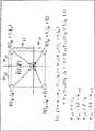
動きベクトル4に基づいてアフィン変換式を決定する。具体的には、被予測画像領域を取り囲む矩形領域の頂点の動きベクトルを用いて、下式のアフィンパラメータ(a,b,c,θ)を決定する。
x'=a(cosθ)x+a(sinθ)y+b
y'=a(-sinθ)x+a(cosθ)y+c
これにより、被予測画像領域の位置(x,y)の画素に対する予測画像位置(x',y')を求め、メモリ読み出しアドレス生成部165に出力する(ステップS104)。
1ー3)予測メモリ指示情報800がメモリcを指示している場合(ステップS106)
動きベクトルに基づいて遠近法変換式を決定する。具体的には、被予測画像領域を取り囲む矩形領域の頂点の動きベクトルを用いて、下式の遠近法パラメータ(a,b,c,d,e,f)を決定する。
x'=(a x+b y+c)/(g x+h y+1)
y'=(d x+e y+f)/(g x+h y+1)
これにより、被予測画像領域の位置(x,y)の画素に対する予測画像位置(x',y')を求め、メモリ読み出しアドレス生成部に出力する(ステップS107)。
2)予測画像生成用データの読み出し
選択された対応点決定部から出力される予測画像位置(x'y')を基に、メモリ読み出しアドレス生成部165がメモリに蓄積されている参照画像中の予測画像生成に必要な画像データの位置を特定するメモリアドレスを生成し、予測画像生成用データを読み出す(ステップS102、S105、S108)。
3)予測画像の生成
予測画像を構成する画素のうち、整数画素位置の画素ならば、予測画像生成用データがそのまま予測画像構成画素となる。一方、実数精度の画素位置の画素の場合、内挿処理部167によって予測画像生成用データの内挿処理によって内挿画素値が生成される(ステップS109,S110,S111)。内挿画素値の生成は図26による。図26において、(ip,jp)は整数画素位置を示し、(i',j')は実数精度の画素位置を示し、wは重みを示す。
4)メモリ(参照画像)の更新
図28に、メモリ更新部115の制御のフローチャートを示す。メモリ更新部115では、予測モード8(又は、予測メモリ指示情報800)に基づいて予測画像取り出しの単位(例えばマクロブロック単位)で各メモリの更新を制御する。メモリaを用いて予測した場合(ステップS112)は、復号画像101によって逐次、メモリaおよびcの内容を更新する(ステップS113)。メモリbを用いて予測した場合(ステップS114)は、メモリbはスタティックスプライトメモリなので、メモリbの参照画像は予測画像取り出しの単位では更新しない。しかし、復号画像101によって逐次、メモリaおよびびcの内容を更新する(ステップS115)。一方、メモリb更新情報1001による更新指示を受けた場合、メモリb更新情報1001に含まれる画像データを受け取りメモリbの内容を全面更新する(ステップS116)。また、メモリcを用いて予測した場合(ステップS117)は、復号画像101によって逐次、メモリaおよびcの内容を更新する(ステップS118)。また、メモリ更新情報により更新指示を受けた場合に、メモリc更新情報1002に含まれる画像データを受け取りメモリcの内容を更新する(ステップS119)。
この実施の形態においては、メモリa,b,cの3つのメモリを用いる場合を示したが、2つのメモリを用いる場合であっても構わない。例えば、メモリaとb、即ち、フレームメモリとスタティックスプライトメモリを用いる場合でも構わない。或いは、メモリaとc、即ち、フレームメモリとダイナミックスプライトメモリを用いる場合でも構わない。
以上のように、本実施の形態の復号装置によれば、画像の動きに対応して様々な種類の動きパラメータを用いて効率よく予測を行った符号化されたビットストリーム21を復号できるとともに、符号化側で定められるタイミングで参照画像の内容を任意に更新する仕組みに対応できるので、より画像の性質に適応した復号処理を行うことが可能である。
本実施の形態では、直交変換符号化以外の別の符号化方式によって予測誤差信号を符号化したビットストリームであっても、動き補償部・メモリ更新部以外の、予測誤差信号復号処理のための部材を変更することで同様の効果を得ることができる。
また、本実施の形態は、固定サイズブロックを単位として復号処理を行うような通常のテレビ信号のフレームを単位とする復号装置に適用できるだけでなく、被予測対象領域を固定サイズブロックに限定せずに、任意形状画像オブジェクト(例:ISO/IEC JTC1/SC29/WG11/N1902で開示されるVideo Object Planeなど)を単位とする復号装置にも適用可能である。
産業上の利用可能性
以上説明したように、この発明によれば、参照用画像を蓄積するメモリ領域を複数個持つので、動画像シーケンスの性質に応じてメモリに振り分けて蓄積することができ、また、複数のメモリ領域のうち1つ以上のメモリ領域の内容を任意のタイミングで更新可能なので、背景画像などの時不変な画像内容は長時間内容の更新を行わず、局所的に変化する画像領域は頻繁にメモリ内容を更新するなどの制御が可能となり、動画像シーケンスの履歴を生かした効率的な予測が行える。
また、複数のメモリ領域それぞれに、各メモリ領域が有効となる変形パラメータ値域を設定し、被予測画像領域の変形パラメータの値に応じてメモリ領域を切り替えて予測に用いるるので、動画像シーケンスの局所的/大域的な動きの大きさに応じて効率的な予測が行える。同時に、被予測画像領域ごとに符号化すべき動きパラメータは参照メモリ領域の有効動きパラメータ値域の範囲内で効率的に復号化することができる。
また、複数のメモリ領域それぞれに、各メモリで有効となる変形手法を設定し、被予測画像領域の変形パラメータの種類に応じてメモリを切り替えて予測できるので、動画像シーケンスの局所的/大域的な動きの複雑さに応じて効率的な予測が行える。同時に、被予測画像領域の動きの性質にあわせて変形手法を適宜選択できることで、動きパラメータを効率的に符号化することができる。Technical field
This invention is, for example,
Video encoding / decoding device used in portable and stationary image communication devices used for video communication applications such as videophones and video conferences,
Video encoding / decoding device used in image storage / recording devices such as digital VTRs and video servers,
Video encoding / decoding program implemented in the form of single software or DSP (Digital Signal Processor) firmware
The present invention relates to prediction of a moving image used for such as.
Background art
As an example of predictive encoding / decoding in the conventional video encoding / decoding method, MPEG-4 (Moving Picture Experts Group Phase-4), which is being standardized by ISO / IEC JTC1 / SC29 / WG11 There is a video encoding / decoding reference method (Verification Model, hereinafter referred to as VM). The content of the VM has changed with the progress of MPEG-4 standardization work. Here, VM Version 5.0 is assumed, and is simply expressed as VM below.
The VM is a system in which a moving image sequence is regarded as a collection of image objects having an arbitrary shape in time / space, and encoding / decoding is performed in units of each image object. The video data structure in VM is shown in FIG. In VM, a moving image object including a time axis is called a Video Object (VO), and image data representing a state of each time of VO and a unit of encoding is called a Video Object Plane (VOP). When the VO has a temporal / spatial hierarchy, a unit called Video Object Layer (VOL) is provided between the VO and the VOP to express the hierarchical structure in the VO. Each VOP is separated into shape information and texture information. However, when there is one VO in the moving image sequence, each VOP is synonymous with a frame. In this case, there is no shape information, and only texture information is encoded / decoded.
As shown in FIG. 30, the VOP has a structure composed of alpha data representing shape information and texture data representing texture information. Each data is defined as an aggregate of blocks (alpha block, macro block) each consisting of 16 × 16 samples. Each sample in the alpha block is represented by 8 bits. The macro block includes a color difference signal corresponding to the luminance signal of 16 × 16 samples. It is assumed that processing for generating VOP data from a moving image sequence is performed outside the present encoding device.
FIG. 31 shows the configuration of a VOP encoding apparatus based on VM encoding / method. In the figure, P1 is input original VOP data, P2 is an alpha block representing VOP shape information, P3a is a switch for transmitting the presence / absence of shape information of the input original VOP data, and P4 is a compression code for the alpha block. P5 is compressed alpha block data, P6 is locally decoded alpha block, P7 is texture data (macroblock), P8 is a motion detector, P9 is a motion parameter, P10 is a motion compensator, and P11 is a prediction Image candidate, P12 is a prediction mode selection unit, P13 is a prediction mode, P14 is a prediction image, P15 is a prediction error signal, P16 is a texture encoding unit, P17 is texture encoding information, P18 is a local decoded prediction error signal, P19 is Local decoding macroblock, P20 is sprite memory update unit, P21 is VOP memory, P22 is sprite Itomemori, P23 variable length coding and multiplexing unit, P24 buffer, P25 is a coded bit stream.
FIG. 32 shows a flowchart summarizing the operation of this encoding apparatus.
In the encoding device of FIG. 31, the original VOP data P1 is first separated into an alpha block P2 and a macroblock P7 (step PS2, step PS3), the alpha block P2 is sent to the shape encoding unit P4, and the macroblock P7 is the motion detection unit. Sent to P8. The shape encoding unit P4 is a processing block (step PS4) for compressing the data of the alpha block P2, and since the present invention is not related to the shape information compression method, the details of the processing are omitted here.
The output of the shape encoding unit P4 is compressed alpha data P5 and a locally decoded alpha block P6. The former is sent to the variable length encoding / multiplexing unit P23, and the latter is the motion detection unit P8, the motion compensation unit P10, and the prediction mode selection. Part P12 and texture encoding part P16.
The motion detection unit P8 (step PS5) receives the macroblock P7, and detects a local motion vector for each macroblock using the reference image data and the locally decoded alpha block P6 stored in the VOP memory P21. Here, the motion vector is an example of a motion parameter. In the VOP memory P21, an already encoded VOP local decoded image is stored. The contents of the VOP memory P21 are sequentially updated with the locally decoded image every time the macroblock is encoded. Furthermore, the motion detection unit P8 also has a function of receiving the entire texture data of the original VOP and detecting a global warping parameter using the reference image data stored in the sprite memory P22 and the locally decoded alpha data. The sprite memory P22 will be described in detail later.
The motion compensation unit P10 (step PS6) generates a predicted image candidate P11 using the motion parameter P9 detected by the motion detection unit P8 and the locally decoded alpha block P6. Next, the prediction mode selection unit P12 determines the final prediction mode P13 and the prediction image P14 of the macroblock using the prediction error signal power and the original signal power (step PS7). The prediction mode selection unit P12 also determines whether the encoding is intraframe encoding or interframe encoding.
In the texture encoding unit P16, the prediction error signal P15 or the original macroblock itself is quantized by DCT (Discrete Cosine Transform) based on the prediction mode P13, and the obtained quantized DCT coefficient is predicted or directly variable length. The data is sent to the encoding / multiplexing unit P23 and encoded (step PS8, step PS9). The variable length coding unit / multiplexing unit P23 converts the received data into a bit stream and multiplexes the data according to a predetermined syntax and a variable length coding code (step PS10). The quantized DCT coefficient is subjected to inverse quantization and inverse DCT to be a locally decoded prediction error signal P18, and then added to the predicted image P14 to obtain a locally decoded macroblock P19 (step PS11). The locally decoded macroblock P19 is written into the VOP memory P21 and the sprite memory P22 and used for subsequent VOP prediction (step PS12).
Below, the part which performs prediction, especially the prediction method and motion compensation, and update control of the sprite memory P22 and the VOP memory P21 will be described in detail.
(1) Prediction method in VM
As shown in FIG. 33, the VM normally has four types of VOP encoding types, and the prediction method indicated by ◯ can be selected for each macroblock for each type. In I-VOP, no prediction is performed at all, and all intra-frame coding is performed. P-VOP can make predictions from past VOPs. B-VOP can use past and future VOPs for prediction.
The above predictions are all motion vector predictions. On the other hand, Sprite-VOP can be predicted using sprite memory. Sprite is the following formula
x '= (a x + b y + c) / (g x + h y + 1)
y '= (d x + e y + f) / (g x + h y + 1)
Warping parameter set shown in
Here, (x, y) is a pixel position on the two-dimensional coordinates of the original VOP, and (x ′, y ′) is a pixel position in the sprite memory associated with (x, y) by the warping parameter. In each Sprite-VOP macroblock, this warping parameter set can be used uniformly to determine (x ′, y ′) in the sprite memory and generate a prediction image for prediction. Strictly speaking, sprites have a distinction between “dynamic sprites” used for prediction and “static sprites” that are used for prediction and used for the purpose of approximately synthesizing VOPs on the decoding side. In FIG. 37, dynamic sprite is used in the meaning of “sprite”.
The motion detection unit P8 detects a motion vector and a warping parameter used for the above prediction. The motion vector and the warping parameter are collectively referred to as a motion parameter P9.
(2) Motion compensation unit
The motion compensation unit P10 has an internal configuration as shown in FIG. In the figure, P26 is a warping parameter, P27 is a motion vector, P28 is a global motion compensation unit, P29 is a local motion compensation unit, P30 is a predicted image candidate based on the warping parameter, and P31 is a predicted image candidate based on a motion vector. The predicted image candidate P11 is a generic term for a predicted image candidate P30 based on warping parameters and a predicted image candidate P31 based on motion vectors.
A flowchart summarizing the operation of the motion compensation unit P10 is shown from step PS14 to step PS21 in FIG.
The motion compensation unit P10 generates a predicted image candidate P11 for each macroblock P7 using the warping parameter P26 of the entire VOP detected by the motion detection unit P8 or the motion vector P27 for each macroblock. The global motion compensation unit P28 performs motion compensation using the warping parameter P26, and the local motion compensation unit P29 performs motion compensation using the motion vector P27.
In I-VOP, the motion compensation unit P10 does not operate (goes from step PS14 to step PS21). In cases other than I-VOP, the local motion compensation unit P29 operates to extract a predicted image candidate (PR1) from a past VOP local decoded image in the VOP memory P21 using the motion vector P27 (step PS15). In P-VOP, only this predicted image candidate (PR1) is used.
If the B-VOP is determined in step PS16, the local motion compensation unit P29 further extracts a predicted image candidate (PR2) from the future VOP local decoded image in the VOP memory P21 using the motion vector P27 ( Step PS17), predictive image candidates (PR3) are obtained by averaging the predicted image candidates obtained from past and future VOP local decoded images (step PS18).
Direct prediction (Prediction based on prediction method equivalent to B frame in ITU-T recommendation H.263 encoding method. Create vector for B frame from paired P-VOP vector. Detailed description is omitted here. In the same manner, a predicted image candidate (PR4) is generated (step PS19). In FIG. 34, a predicted image candidate P31 based on a motion vector is a generic name of a part or all of the predicted image candidates PR1 to PR4.
If it is neither an I-VOP nor a B-VOP, it is a Sprite-VOP, and a predicted image candidate (PR1) is extracted from the VOP memory using a motion vector, and at step PS20, the global motion compensation unit P28 uses the warping parameter P26. A predicted image candidate P30 is extracted from the sprite memory P22.
The global motion compensation unit P28 calculates an address where the predicted image candidate in the sprite memory P22 exists from the warping parameter P26, and extracts and outputs the predicted image candidate P30 from the sprite memory P22 based on the calculated address. The local motion compensation unit P29 calculates an address where the predicted image in the VOP memory P21 exists from the motion vector P27, and extracts a predicted image candidate P31 from the VOP memory P21 based on the calculated address.
These prediction image candidates P11 are evaluated by the prediction mode selection unit P12 including the intra-frame encoded signal of the texture data P7, and the prediction image candidate and the prediction mode with the smallest prediction error signal power are selected.
(3) Memory update
Memory update control (step PS12) is performed by the memory update unit P20, and the VOP memory P21 and the sprite memory P22 are updated. These memory contents are updated regardless of the prediction mode P13 selected for each macroblock.
The internal configuration of the memory update unit P20 is shown in FIG. 36, and the flowchart showing the operation of the memory update unit P20 is shown in steps PS22 to PS28 in FIG.
In FIG. 36, P32 is a VOP encoding type given from the outside, P33 is a sprite prediction identification flag given from the outside indicating whether or not to make a prediction using the sprite memory, and P34 is used for a prediction using the sprite memory. P35 is a switch, P36 is a switch, P37 is a sprite composition unit, P38 is a sprite deformation processing unit, P39 is a VOP memory update signal, and P40 is a sprite update signal.
First, the sprite prediction identification flag P33 checks whether the VO or VOL specifies that the sprite is to be used (step PS22). If the sprite is not used, B-VOP is checked (step PS27). If it is a VOP, the VOP memory P21 is not updated at all. In I-VOP or P-VOP, the local decoding macroblock P19 is overwritten on the VOP memory P21 for each macroblock (step PS28).
On the other hand, if it is determined that a sprite is used in the check at step PS22, first, the VOP memory P21 is updated as described above (step PS23, step PS24), and then the sprite memory P22 is updated according to the following procedure. Is called.
a) Warping of sprite (Step PS25)
First, in the sprite deformation processing unit P38, an area on the sprite memory (area having the same area as the VOP having the position on the sprite memory as the origin when the time of the VOP is t)
b) Blending of sprites (Step PS26)
Using the warped image obtained as a result of the above a), in the sprite synthesis unit P37, a new sprite memory area according to the following equation:
However, for regions that do not belong to VOP in the local decoding macroblock,
In the prediction method in the conventional coding method as described above, when predicting a moving image object, a memory that only detects a motion vector and a memory that only detects a warping parameter can be used for only one screen at maximum. Therefore, a reference image that can be used for prediction is used only by a very limited method, and the prediction efficiency cannot be sufficiently improved.
Further, even in a system in which a plurality of moving image objects are encoded at the same time, these memories include only reference images indicating the history of the predicted moving image objects themselves, so that variations of reference images are limited. In addition, prediction cannot be performed using the correlation between moving image objects.
Furthermore, even when updating the memory, the memory is rewritten regardless of the internal structure, properties, history, etc. of the moving image object, so important knowledge for predicting the moving image object cannot be sufficiently accumulated in the memory, There was a problem that the prediction efficiency could not be improved.
The present invention has been made to solve the above-mentioned problems. When encoding / decoding image data, a plurality of memories are provided, and a plurality of memories are considered in consideration of the internal structure and properties of the moving image sequence. To effectively store a history of a moving image sequence in a memory to improve prediction and encoding / decoding efficiency, and to provide a more flexible prediction method by providing a structure capable of prediction between a plurality of moving image objects. With the goal.
Disclosure of the invention
The present invention accumulates image data to be referred to in prediction, inputs a plurality of memories each associated with an individual deformation method, and a parameter expressing motion of the predicted image region, and the predicted image region A prediction image generation unit that generates a prediction image based on the above-described parameter and a deformation method associated with the memory, using image data stored in a memory used for the prediction, and includes at least an encoding device and a decoding This is a moving picture prediction method for predicting a moving picture that is used in any of the apparatuses.
The encoding device generates a prediction memory instruction information signal indicating the memory used to generate the prediction image, and the decoding side uses the image data stored in the memory to change the memory. The prediction memory instruction information signal and the parameter are transmitted to the decoding side so that the prediction image can be generated based on a technique.
The decoding apparatus receives the parameter and prediction memory instruction information indicating the memory used to generate the prediction image from the encoding side, and the prediction image generation unit applies a modification method associated with the parameter and the memory. Based on the above, the predicted image is generated using the image data stored in the memory.
In addition, the present invention accumulates image data to be referred to at the time of prediction, inputs a plurality of memories each of which is associated with an individual parameter effective value range, and a parameter expressing the motion of the predicted image region. A prediction image generation unit that selects a memory associated with the parameter effective value range including the value of the image and generates a prediction image using the image data stored in the selected memory, and includes at least encoding and decoding This is a moving picture prediction method for predicting a moving picture characterized by being used for any one of them.
The present invention also inputs a plurality of memories that store image data to be referred to in prediction and a parameter that expresses the motion of the predicted image area, and stores the image data stored in the plurality of memories based on the parameters. A prediction image generation unit including a motion compensation unit that generates a prediction image using a memory update unit that updates image data stored in at least one of the plurality of memories at an arbitrary timing. This is a moving picture prediction method for predicting a moving picture, which is characterized in that the moving picture is used for any one of encoding and decoding.
The moving image prediction method predicts a moving image on a moving image sequence having first and second moving image objects, and the plurality of memories have a first corresponding to the first and second moving image objects. And the second individual plurality of memories, the predicted image generation unit includes first and second individual generation units corresponding to the first and second moving image objects, and the first When generating the first object, the generating unit generates the predicted image using image data stored in at least one of the first and second memories, and second The information indicating whether or not the plurality of memories are used for prediction of the first object is generated for adding to the predicted image.
The predicted image generation unit generates the predicted image by increasing or decreasing either the number or the size of the plurality of memories according to a change in the moving image at each time.
The predicted image generation unit generates a predicted image by limiting a memory used for prediction according to a change in a moving image at each time.
The predicted image generation unit generates a predicted image by calculating a plurality of predicted images respectively generated using the image data stored in the plurality of memories.
The moving picture prediction method includes an importance level detection unit that detects a feature amount parameter indicating the importance level of the predicted image region, and the prediction image generation unit includes at least a plurality of prediction methods based on the feature amount parameter. The prediction image is generated by selecting at least one of a plurality of options for any of the plurality of memories and the plurality of memory update methods.
The moving picture prediction method is an importance detection that detects at least a code amount that can be used by a predicted image area, a change amount of the image area at each time, and a parameter that represents the importance of the image area. The prediction image generation unit selects at least one of a plurality of options for at least one of a plurality of prediction methods, a plurality of memories, and a plurality of memory update methods based on the parameter. A prediction image is generated.
The moving image prediction method predicts a moving image in units of moving image objects, and the moving image prediction method includes at least a code amount that can be used by the predicted moving image object and a change amount of the moving image object at each time. And an importance level detection unit that detects a parameter representing one of the importance levels of the moving image object, and the predicted image generation unit, based on the parameters, at least a plurality of prediction methods, a plurality of memories, A prediction image is generated by selecting at least one of a plurality of options for one of a plurality of memory update methods.
The moving image prediction method includes a prediction information encoding unit that encodes information related to prediction in encoding of a moving image, and the predicted image generation unit counts the frequency of use of a memory used for prediction. And determining the ranks of the plurality of memories based on the counted number of use frequencies, and the prediction information encoding unit predicts by assigning a code length to information related to prediction according to the ranks of the memories used for prediction It is characterized by encoding information related to the above.
The plurality of memories include at least a frame memory for storing image data in units of frames and a sprite memory for storing sprite images.
The sprite memory has at least one of a dynamic sprite memory with sequential update and a static sprite memory without sequential update.
The plurality of memories are characterized in that at least one of transformation methods among parallel movement, affine transformation, and perspective transformation is associated with the changeable manner.
Further, the present invention inputs a step of storing image data to be referred to in prediction in a plurality of memories, a step of associating each of the plurality of memories with an individual deformation method, and a parameter expressing the motion of the predicted image region And using the image data stored in the memory used for the prediction of the predicted image area to generate a predicted image based on the parameter and a deformation method associated with the memory, This is a method for predicting a moving image, which is characterized in that it is used for either conversion or decoding.
The method for predicting the moving image further includes a step of generating a prediction memory instruction information signal indicating the memory using the prediction image generation, and a step of transmitting the prediction memory information signal and the parameter to the decoding side. It is characterized by having.
The method for predicting a moving image further includes a step of receiving a prediction memory instruction information signal indicating a memory used for generating a prediction image and a parameter expressing a motion of a predicted image region from the encoding side, and is used for decoding. It is characterized by being able to.
The present invention also includes a step of storing image data to be referred to in prediction in a plurality of memories, a step of associating individual parameter effective value ranges with the plurality of memories, and a parameter expressing the motion of the predicted image region. An input step, a step of selecting a memory associated with the parameter effective value range including the value of the parameter, and a step of generating a predicted image using image data stored in the selected memory, This is a method for predicting a moving image characterized by being used for either encoding or decoding.
The present invention also includes a step of storing image data to be referred to in prediction in a plurality of memories, a step of inputting a parameter expressing the motion of the predicted image region, and a storage in the plurality of memories based on the parameters. A step of generating a predicted image using the processed image data, and a step of updating image data stored in at least one of the plurality of memories at an arbitrary timing, and at least one of encoding and decoding This is a method for predicting a moving image characterized by being used.
[Brief description of the drawings]
FIG. 1 is a block diagram showing a moving picture coding apparatus according to an embodiment of the present invention.
FIG. 2 is a flowchart showing the operation of the moving picture coding apparatus according to the embodiment of the present invention.
FIG. 3 is a block diagram showing the configuration of the motion compensation unit of the moving picture coding apparatus according to the embodiment of the present invention.
FIG. 4 is a flowchart showing the operation of the motion compensation unit.
FIG. 5 is a configuration diagram showing the configuration of the memory updating unit of the moving picture encoding apparatus according to the embodiment of the present invention.
FIG. 6 is a flowchart showing the operation of the memory update unit.
FIG. 7 is a block diagram showing the configuration of the motion compensation unit of the moving picture coding apparatus according to the embodiment of the present invention.
FIG. 8 is a flowchart showing the operation of the motion compensation unit of FIG.
FIG. 9 is a block diagram showing the configuration of the motion compensation unit of the moving picture coding apparatus according to the embodiment of the present invention.
FIG. 10 is a flowchart showing the operation of the motion compensation unit of FIG.
FIG. 11 is a block diagram showing a moving picture coding apparatus according to the embodiment of the present invention.
FIG. 12 is a block diagram showing the configuration of the motion compensation unit of the moving picture coding apparatus according to the embodiment of the present invention.
FIG. 13 is a flowchart showing the operation of the motion compensation unit of FIG.
FIG. 14 is a configuration diagram showing the configuration of the memory update unit of the moving picture encoding apparatus according to the embodiment of the present invention.
FIG. 15 is a flowchart showing the operation of the memory update unit of FIG.
FIG. 16 is a block diagram showing a moving picture coding apparatus according to the embodiment of the present invention.
FIG. 17 is a block diagram showing a moving picture coding apparatus according to the embodiment of the present invention.
FIG. 18 is a block diagram showing a moving picture coding apparatus according to the embodiment of the present invention.
FIG. 19 is a block diagram showing a moving picture coding apparatus according to the embodiment of the present invention.
FIG. 20 is a diagram showing the
FIG. 21 is a diagram showing the
FIG. 22 is a diagram showing the
FIG. 23 is a diagram showing the
FIG. 24 is a block diagram showing a moving picture decoding apparatus according to the embodiment of the present invention.
FIG. 25 is a block diagram showing the configuration of the motion compensation unit of the video decoding device in the embodiment of the present invention.
FIG. 26 is a flowchart showing the operation of the motion compensation unit.
FIG. 27 is a diagram for explaining the interpolation processing.
FIG. 28 is a flowchart showing the operation of the memory update unit of the video decoding device in the embodiment of the present invention.
FIG. 29 is an explanatory diagram showing a video data structure in the VM encoding method.
FIG. 30 is an explanatory diagram showing the structure of VOP data.
FIG. 31 is a configuration diagram illustrating a configuration of the VM encoding device.
FIG. 32 is a flowchart showing the operation of the encoding apparatus of FIG.
FIG. 33 is an explanatory diagram of prediction types corresponding to VOP coding types.
FIG. 34 is a configuration diagram illustrating a configuration of a motion compensation unit in the encoding device in FIG. 31.
FIG. 35 is a flowchart showing the operation of the motion compensation unit of FIG.
FIG. 36 is a configuration diagram illustrating a configuration of a memory update unit in the encoding device in FIG. 31.
FIG. 37 is a flowchart showing the operation of the memory update unit of FIG.
BEST MODE FOR CARRYING OUT THE INVENTION
FIG. 1 is a block diagram showing a configuration of a coding apparatus according to the first embodiment and embodiments described later. In the figure, 1 is an input video signal, 2 is texture data, 3 is a motion detection unit, 4 is a motion parameter, 5 is a motion compensation unit, 6 is a predicted image candidate, 7 is a prediction mode selection unit, and 8 is a prediction mode. , 9 is a prediction image, 10 is a prediction error image, 11 is a texture encoding unit, 12 is a quantized DCT coefficient, 13 is a locally decoded prediction error image, 14 is a local decoded image, 15 is a memory update unit, 16 is Memory a, 17 is memory b, 18 is memory c, 19 is a variable length encoding / multiplexing unit, 20 is a transmission buffer, 21 is a bit stream, 80 is a scene change detection unit, and 81 is a timer. Among them, the
In this embodiment, a plurality of, for example, three memories are selectively used according to the importance based on image features such as the amount of motion and chromaticity of the input moving image, and any memory (area), for example, at any time interval, A mechanism for updating the contents of the memory a is provided. The moving image sequence is input in units of frames.
(1) Input signal
As described above, the encoding apparatus inputs a frame representing an image at each time of the moving image sequence as a unit, and the frame is divided into macroblocks that are encoding units as an example of a predicted image region (step S1). ).
(2) How to use memory
In the memory, images that have been decoded in the past or previously fixed images are stored. In this embodiment, depending on the importance of the partial areas in the frame, the three memories are Use properly like this.
Memory a: Accurate image area (= background image area where motion is stationary or uniform and texture is uniform) is stored.
Memory b: Accurate image area (= image area with relatively small motion due to subject movement) is accumulated.
Memory c: An image area with a high degree of importance (= an image area with a large movement due to the movement of the subject) is accumulated.
The less important image area stored in the memory a can be considered as a background image area appearing in a video conference scene or the like. It also corresponds to a background area in a scene that includes a subject with a slight movement and includes a uniform movement of the entire screen by a camera operation. These motions are efficient if the motion of the entire frame is obtained in advance rather than a small unit called a macro block, and that motion is substituted for the motion of the macro block. That is, a deformation parameter corresponding to the warping parameter in the sprite described in the conventional example is obtained, and the deformation parameter of the entire frame is regarded as a motion parameter of each macroblock. The motion parameter may be a simple translation parameter (= synonymous with a motion vector), an affine including deformation, a perspective motion parameter, or the like. Here, the motion vector is an example of a motion parameter.
The image area of medium importance stored in the memory b is, for example, an image area of a person whose body is moving without speaking in a video conference scene, and is considered as a subject area with a low degree of attention on the screen. Can do. The image area with a high degree of importance stored in the memory c can be considered as a subject area having the highest degree of attention such as a speaker in a video conference scene.
Since the areas accumulated in the memories b and c have a subject-specific motion, it is natural to consider that the macroblock has different motion parameters. The motion parameters at this time may be simple translation parameters (= synonymous with motion vectors), affine including deformation, perspective motion parameters, or the like.
(3) Motion detection (step S2)
The
(4) Motion compensation (step S3)
The internal configuration of the
First, if it is I (Intra) -frame, motion compensation is not performed (step S11). If it is not an I-frame, a predicted image candidate is generated based on the global motion parameter detected by the
In this embodiment, since both the global motion parameter and the local motion parameter are based on the same modification method, any predicted image generation can be shared by the
(5) Selection of prediction mode (step S4)
The prediction mode in this embodiment is:
(A) Mode using memory a,
(B) a mode using the memory b,
(C) mode using memory c,
(D) Mode using intra-frame coded signal
There shall be. For example, as shown in the conventional example, the prediction
(6) Memory update
The
The memory update in this embodiment follows the following procedure. When the
(1) Every frame of the memories b and c is updated (steps S20 and S21).
The locally decoded
(2) Update arbitrary frame in memory a (steps S22 and S23)
Based on the memory a
The contents of the memory a are so-called history of a time-invariant image area such as a background image, and it is not necessary to update the contents of the memory unless the contents of the area change greatly due to a scene change or a large movement of the entire screen.
As described above, if a moving region such as a subject is sequentially updated on a frame basis and the contents of the memory a are updated at a longer time interval, it is effective in predicting a background image that appears and disappears due to the movement of the subject. Is.
In this embodiment, a mechanism for updating the memory a at an arbitrary time interval is provided from the above viewpoint. Specifically, for example,
a. Based on the size of the global motion parameter, if the movement is large, the content of the entire screen is updated all at once.
b. A method for updating the contents of the entire screen at a certain time, not limited to the time interval between frames,
c. When a scene change is detected, the entire screen content is updated all at once in the frame immediately after the scene change.
Arbitrary update criteria such as
In this embodiment, the data used as the arbitrary update determination criterion as described above is collectively referred to as an
If it is determined that the contents of the memory a are to be updated, the contents of the locally decoded
Note that the memory a
FIG. 20 is a diagram showing the
FIG. 20 conceptually shows how frame data is sequentially encoded and transferred. Header information is added to the head of each frame data as additional information in units of frames. In addition, the memory a
Although not shown, the memory b update information and / or the memory c update information may be transferred to the decoding side together with or instead of the memory a
The encoding apparatus described above provides a mechanism for efficiently using a plurality of memories in accordance with the contents of a moving image sequence, thereby improving prediction efficiency. In other words, when predicting a moving image sequence, a plurality of memories are used depending on the content and properties of the moving image sequence and prediction based on an arbitrary deformation parameter is performed. It is possible to configure an encoding device that can perform efficient moving picture tracking that follows, improve prediction efficiency, and reduce the amount of encoded data while maintaining the quality of the encoded image. In addition, a decoding device that decodes a bitstream encoded based on the prediction method of the present invention can also be configured by a similar prediction method.
In this embodiment, an apparatus for encoding each frame has been described. However, the same effect can be expected for an apparatus for encoding a moving image object (VOP) having an arbitrary shape.
Also, in this embodiment, the encoding device using macroblocking as a unit is described as an example of the predicted image region. However, the encoding device is configured by an image unit such as a partial image having an arbitrary shape or a combination of a plurality of fixed size blocks. The same effect can be expected for an apparatus that encodes an image in units of an image such as a deformable block.
In this embodiment, the global motion parameter detection using the memory a is used. However, it goes without saying that a configuration using only local motion detection without using this is applicable. When global motion detection is not performed, it is not necessary to transmit discrimination information for global / local prediction as a prediction mode.
In this embodiment, it is possible to provide a memory in which reference image data generated based on the contents of a moving image sequence is stored in advance and not updated during encoding, and used for prediction.
In this embodiment, the
The same applies to the embodiments described below.
In this embodiment, the case where three memories a, b, and c are used is shown, but any two memories may be used.
In addition, a decoding apparatus using the predicted
Next, in the encoding apparatus having the configuration shown in FIG. 1, an embodiment of the encoding apparatus in which only the configuration of the
The internal configuration of the
First, if it is an I-frame, motion compensation is not performed (step S24). If it is not an I-frame, the reference
For example, when a motion vector is detected, if the search range is ± 15 pixels, the effective motion parameter value range is ± 9 to 3 pixels, the memory a is from ± 4 to 8 pixels, and the memory b is ± 9. Means an effective search range for each memory such that the memory c is used for prediction in the range of 15 pixels to 15 pixels. However, when the predicted image is generated with the global motion parameter, since the reference memory is determined as the memory a, the reference
Next, a predicted
In this embodiment, since both the global motion parameter and the local motion parameter are based on the same modification method, any predicted image generation can be shared by the
The effective motion parameter value range may be a constant region for each moving image sequence, but may be changed for each frame, for example. When changing every frame, the effective motion parameter value range of each memory in the frame is multiplexed to a bit stream and transmitted to the decoding side so that the same memory selection can be performed on the decoding side.
FIG. 21 is a diagram showing the
At the beginning of this bit stream, there is header information added in units of moving image sequences. This header information includes effective motion parameter range instruction information for each memory. As described above, by specifying the effective motion parameter range instruction information at the head of the moving image sequence, the decoding apparatus can perform a prediction method using the effective motion parameter range of a certain range for the moving image sequence.
When the effective motion parameter value range is changed for each frame, the effective motion parameter instruction information in the header information added for each frame may be included.
The encoding apparatus having the configuration of the
In this embodiment, an apparatus for encoding each frame has been described. However, the same effect can be expected for an apparatus for encoding a moving image object (VOP) having an arbitrary shape.
Also, in this embodiment, the coding apparatus in units of macroblocks has been described, but a variable shape block configured by a combination of image units such as partial images having an arbitrary shape or a plurality of fixed size blocks, etc. The same effect can be expected for an apparatus that encodes images in units of images.
In this embodiment, the global motion parameter detection using the memory a is used. However, it goes without saying that a configuration using only local motion detection without using this is applicable. When global motion detection is not performed, it is not necessary to transmit discrimination information for global / local prediction as a prediction mode.
It is also possible to configure a decoding apparatus using the predicted
Next, in the encoding apparatus having the configuration shown in FIG. 1, an embodiment of an encoding apparatus in which only the configuration of the
The memory a in this embodiment is a frame memory for storing one frame of reference images, the memory b is a static sprite memory, and the memory c is a dynamic sprite memory.
FIG. 9 shows the internal configuration of the
First, if it is an I-frame, motion compensation is not performed (step S33). If it is not an I-frame, the predicted image memory
Each predicted image memory address calculation unit calculates an address based on the image transformation method assigned to each corresponding memory. In this embodiment, parallel movement is used for the memory a, affine parameters with simple deformation such as rotation and enlargement / reduction to some extent are used for the memory b, and perspective parameters with three-dimensional and complicated motion are used for the memory c. These deformation methods can be expressed by the following conversion formulas.
[Translation]
Translation amount (a, b):
x '= x + a
y '= y + b
[Affine transformation]
Affine parameters (a, b, c, θ):
x '= a (cosθ) x + a (sinθ) y + b
y '= a (-sinθ) x + a (cosθ) y + c
[Performance conversion]
Perspective parameters (a, b, c, d, e, f):
x '= (a x + b y + c) / (g x + h y + 1)
y '= (d x + e y + f) / (g x + h y + 1)
Here, (x, y) on the two-dimensional coordinates is the pixel position of the original macroblock, and (x ′, y ′) is the pixel position in the memory associated with (x, y) by each parameter. That is, the position is calculated on the memory (x ′, y ′) based on these parameters. By having this mechanism, it is possible to perform prediction from a memory having the most suitable motion characteristics for each macroblock. Based on the predicted
Note that the type of modification method of each memory in the frame is multiplexed as the motion detection method instruction information in the
FIG. 22 is a diagram showing the
The header information added to the head of the moving image sequence includes motion detection method instruction information. In the encoding device, the type of the deformation method used in each memory can be changed, and motion detection method instruction information indicating this correspondence is sent to the decoding device as header information of the moving image sequence. In this way, the decoding apparatus can identify the type of deformation method used in each memory.
In the decoding device, the type of the identified modification method is dynamically associated with each memory.
The encoding apparatus having the configuration of the
In this embodiment, an apparatus for encoding each frame has been described. However, the same effect can be expected for an apparatus for encoding a moving image object (VOP) having an arbitrary shape.
Also, in this embodiment, the coding apparatus in units of macroblocks has been described, but a variable shape block configured by a combination of image units such as partial images having an arbitrary shape or a plurality of fixed size blocks, etc. The same effect can be expected for an apparatus that encodes images in units of images.
In this embodiment, the global motion parameter detection using the memory a is used. However, it goes without saying that a configuration using only local motion detection without using this is applicable. When global motion detection is not performed, it is not necessary to transmit discrimination information for global / local prediction as a prediction mode.
In this embodiment, the case where the memories a, b, and c are used is shown. However, when only the memories a and b are used, when the memories a and c are used, or only the memories b and c are used. It does not matter.
It is also possible to configure a decoding device using the predicted
Next, a description will be given of an embodiment of an apparatus that targets a moving image sequence in which a plurality of, for example, two different moving image objects having shape information are mixed, and encodes these moving image objects collectively. FIG. 11 shows the configuration of the encoding apparatus according to this embodiment.
In this figure, 42 is an input image frame, 43 is an object separation unit, 44a and 44b are object data, 45a and 45b are shape blocks, 46a and 46b are switches, 47a and 47b are shape coding units, and 48a and 48b are compressions. Shape block data, 49a and 49b are locally decoded shape blocks, 50a and 50b are texture data (macro blocks), 51a and 51b are motion detection units, 52a and 52b are motion parameters, 53a and 53b are motion compensation units, and 54a and 54b. Are prediction image candidates, 55a and 55b are prediction mode selection units, 56a and 56b are prediction mode information, 57a and 57b are prediction images, 58a and 58b are prediction error signals, 59a and 59b are texture encoding units, and 60a and 60b are Compressed texture data, 61a and 61b are local decoding prediction error signals 62a and 62b are local decoding macroblocks, 63 is a memory update unit, 64 is a memory a, 65 is a memory b, 66 is a memory c, 67 is a memory d, 68 is a memory e, 69 is a memory f, 70a and 70b are variable A long encoding unit, 71 is a multiplexing unit, 72 is a buffer, 73 is a bit stream, 94 is a memory unit, 88a is an A object encoding unit that encodes an A object, and 88b is a B object code that encodes a B object. Is The
The encoding apparatus receives an
The shape information of the object is sent to the
The
However, in principle, the memories a to c are used for the A object encoded by the A
Further, as the types of motion, it is assumed that the distinction between motion vectors and warping parameters is removed, and arbitrary deformation parameters can be detected in units of macroblocks for all memories in the
After the
The A / B object data encoded by the A / B object encoding
Hereinafter, the prediction in this embodiment will be described focusing on the
The
In FIG. 12, 74a is a B object reference determination unit, and 75a is a B object reference instruction flag.
Here, the
The B object
The encoding device having the configuration of the
In this embodiment, an apparatus for encoding an object in units of macroblocks has been described. However, a unit such as a partial image having an arbitrary shape or a variable shape block configured by a combination of a plurality of fixed size blocks is used. The same effect can be expected for the encoding apparatus.
It is also possible to configure a decoding device using the same members as the
Next, an embodiment of an encoding device having a configuration in which the number or capacity of memories can be freely changed in response to temporal changes of moving image objects will be described. In the fifth embodiment, an encoding apparatus is considered in which the configuration of the
FIG. 14 shows the internal configuration of the
When an image remarkably different from the history of the moving image sequence stored in the memory due to a scene change or the like appears, in the prediction after the scene change, the prediction efficiency may be deteriorated only with the reference image included in the existing memory. . In such a case, if the scene change is detected by the scene
In addition, since there is a physical limit to the capacity of the memory that can be added, a mechanism that can sequentially degenerate a portion of the reference image on the memory that is hardly used for prediction is provided. The frequency used for prediction of each memory area of the memories a, b, and c is measured by the
From the above point of view, the
For the memory a, as in the first embodiment, the memory a
These memory contents are updated with the determination of memory expansion / degeneration. The memory
The encoding apparatus having the configuration of the
In this embodiment, an apparatus for encoding each frame has been described. However, the same effect can be expected for an apparatus for encoding a moving image object (VOP) having an arbitrary shape.
In this embodiment, an apparatus for encoding a frame in units of macroblocks has been described. However, a variable shape block configured by a combination of image units such as partial images having an arbitrary shape or a plurality of fixed size blocks. The same effect can be expected for an apparatus that encodes an image in units of images such as regions.
It is also possible to configure a decoding device using the same members as those of the
In each of the above embodiments, the case where the memory used for prediction in the macroblock is changed has been shown. However, the prediction is performed by changing the memory used for prediction in units of frames or moving image objects. You can also. This eliminates the need to encode memory-related information to be encoded in units of frames or moving image objects and memory selection information to be encoded in units of macroblocks (included in the prediction mode 8). Can be made.
For example, in the encoding apparatus of FIG. 1 in
In each of the above-described embodiments, an image obtained by averaging two predicted image candidates extracted from an arbitrary plurality of, for example, two memories (for example, memories a and b) out of a plurality of memories is a predicted
In the encoding device described in each of the above embodiments, feature amount parameters that define the spatial complexity, gaze degree, and the like of an image area that is a unit for prediction are detected in advance, and these are used as prediction modes. It is possible to adopt a configuration that is used as a determination scale for determination and memory update.
For example, a moving image that includes complex motion and is difficult to perform encoding that achieves acceptable quality within a given code amount is assumed. In such a case, the importance is determined for each predicted image area (macroblock, arbitrary shape image area, arbitrary shape block, etc.), and the lower importance area decreases the quality to some extent to reduce the code amount. To improve the overall quality by assigning them to areas of high importance. In an apparatus for performing prediction by switching a plurality of memories at an arbitrary timing as in the present invention, a feature parameter indicating the importance of a predicted image area is detected, and a memory usage method is dynamically determined based on the feature parameter. By doing so, it is possible to perform prediction more adapted to the nature of the image. For example, as shown in FIG. 16, a region importance
In an apparatus that predicts and encodes a video sequence using a plurality of memories, the amount of code that can be used at each time of the video sequence, or the amount of scene change (scene change detection, etc.) at that time, The parameters such as the feature amount and importance of the image area to be predicted as described in 8 are detected, and these values are used to predict the image at that time, or the selection of the reference memory area It is possible to adopt a configuration that is used as a determination scale in the case of. For example, as shown in FIG. 17, a frame
The idea of this embodiment is that even when encoding is performed with software in which the processing process and the amount of usable memory are fluid, the encoding process can be performed efficiently by making the best use of available resources. Applicable. The amount of processing can be reduced in frames with low importance, and the overall processing speed can be improved.
As shown in FIG. 11, in a device that predicts and encodes a moving image sequence composed of a plurality of moving image objects using a plurality of memories, the total code amount that can be used as a sequence, and each time of each moving image object The amount of code that can be used in the video, the amount of change in the moving image object at the time (appearance, concealment, etc.), the level of importance / gaze level in the scene of each moving image object, 9. Prediction method or reference memory area in which parameters such as the feature amount and importance of the predicted image area described in 9 are detected and these values can be used for prediction of the moving image object at the time. It is possible to take a configuration that is used as a determination scale for selection of.
For example, as shown in FIG. 18,
In addition, as illustrated in FIG. 19, a prediction
In a device that predicts and encodes a moving image sequence or a moving image object using a plurality of memories a, b, and c, the plurality of memories are ranked according to the frequency of use of the memory used for prediction, and this rank The code allocation of the encoding information (reference memory number, etc.) related to the prediction in the prediction
For example, in the encoding device of FIG. 19, the
This makes it possible to recognize how much memory is used for prediction and how often. A memory frequently used for prediction is a memory having high importance in performing prediction, and the higher the reference frequency, the higher the rank.
In this way, when encoding memory frequency information used for prediction for each predicted image region unit, it is more efficient to assign a short code length to a frequently referred memory (= high-rank memory). Rise.
In addition, if a motion parameter detected for each predicted image region unit can be assigned a code length corresponding to the rank of the referenced memory, a shorter code length can be assigned to a frequently occurring motion parameter value. Thus, efficient encoding of prediction information becomes possible. These mechanisms are such that the prediction
FIG. 24 shows the configuration of an image decoding apparatus for decompressing and reproducing a compression-encoded digital image in the present embodiment. In the figure, 21 is an encoded bit stream, 119 is a variable length decoding unit, 12 is a quantized DCT coefficient, 12a is a quantized orthogonal transform coefficient, 12b is a quantization step, 111 is a texture decoding unit, and 111a is an inverse quantum. , 111b is an inverse orthogonal transform unit, 190 is a decoding addition unit, 101 is a decoded image, 191 is a display control unit, 8 is a prediction mode, 1001 is memory b update information, 1002 is memory c update information, 4 is a motion vector (Motion parameter), 800 is prediction memory instruction information, 195 is a position in the screen of the predicted image area, 105 is a motion compensation unit, 116 is a memory a, 117 is a memory b, 118 is a memory c, 115 is a memory update unit, Reference numeral 106 denotes a predicted image. The
In this embodiment, the memory a is a frame memory that stores image data for one frame, the memory b is a static sprite memory, and the memory c is a dynamic sprite memory. In addition, it is assumed that the decoding apparatus of this embodiment receives the
The operation of the apparatus having the above configuration will be described below. First, the variable
The
Based on the
Next, a predicted image generation process in the
(1) When the memory a is used for prediction (= when the prediction
The coordinates of each pixel in the prediction target area are translated by the motion vector, and image data at a corresponding position in the memory a is extracted as a predicted image.
(2) When the memory b is used for prediction (= when the prediction memory instruction information indicates the use of the memory b)
An affine transformation formula is obtained based on the motion vector, the coordinates of each pixel in the prediction target region are displaced by the transformation formula, and image data at a corresponding position in the memory c is taken out as a prediction image.
(3) When the memory c is used for prediction (= when the use memory instruction information indicates the use of the memory c)
A perspective conversion formula is obtained based on the motion vector, the coordinates of each pixel in the prediction target region are displaced by the conversion formula, and image data at a corresponding position in the memory b is extracted as a predicted image.
The internal configuration of the
Hereinafter, the operation of the
1) Determination of corresponding points
First, the corresponding point determination unit for the corresponding memory is selected by the switch 161 based on the prediction
1-1) When the prediction
A predicted image position is calculated by parallel movement using a motion vector (step S101). Specifically, the predicted image position (x ′, y ′) for the pixel at the position (x, y) of the predicted image region is determined by the following equation based on the motion vector (a, b).
x '= x + a
y '= y + b
The determined predicted image position is output to the memory read
1-2) When the prediction
An affine transformation formula is determined based on the
x '= a (cosθ) x + a (sinθ) y + b
y '= a (-sinθ) x + a (cosθ) y + c
Thereby, the predicted image position (x ′, y ′) for the pixel at the position (x, y) in the predicted image region is obtained and output to the memory read address generation unit 165 (step S104).
1-3) When the prediction
A perspective transformation formula is determined based on the motion vector. Specifically, the perspective parameters (a, b, c, d, e, f) of the following equation are determined using the motion vectors of the vertices of the rectangular area surrounding the predicted image area.
x '= (a x + b y + c) / (g x + h y + 1)
y '= (d x + e y + f) / (g x + h y + 1)
Thereby, the predicted image position (x ′, y ′) for the pixel at the position (x, y) in the predicted image region is obtained and output to the memory read address generation unit (step S107).
2) Reading prediction image generation data
Based on the predicted image position (x′y ′) output from the selected corresponding point determination unit, the memory read
3) Prediction image generation
If a pixel is an integer pixel position among the pixels constituting the predicted image, the predicted image generation data is directly used as the predicted image constituent pixel. On the other hand, in the case of a pixel at a pixel position with real number precision, an interpolation pixel value is generated by interpolation processing unit 167 by interpolation processing of predicted image generation data (steps S109, S110, and S111). The generation of the interpolated pixel value is as shown in FIG. In FIG.p , jp ) Indicates an integer pixel position, (i ′, j ′) indicates a pixel position with real precision, and w indicates a weight.
4) Update memory (reference image)
FIG. 28 shows a flowchart of control of the
In this embodiment, the case where three memories a, b, and c are used is shown, but two memories may be used. For example, the memories a and b, that is, a frame memory and a static sprite memory may be used. Alternatively, the memories a and c, that is, the frame memory and the dynamic sprite memory may be used.
As described above, according to the decoding apparatus of the present embodiment, it is possible to decode the encoded
In the present embodiment, even for a bit stream obtained by encoding a prediction error signal by another encoding method other than orthogonal transform encoding, a prediction error signal decoding process other than the motion compensation unit and the memory update unit is performed. Similar effects can be obtained by changing the members.
In addition, the present embodiment can be applied not only to a decoding device in units of frames of a normal television signal that performs decoding processing in units of fixed size blocks, but also does not limit the prediction target region to fixed size blocks. In addition, the present invention can also be applied to a decoding device in units of arbitrary shape image objects (eg, Video Object Plane disclosed in ISO / IEC JTC1 / SC29 / WG11 / N1902).
Industrial applicability
As described above, according to the present invention, since there are a plurality of memory areas for storing the reference images, they can be distributed and stored in the memory according to the nature of the moving image sequence. The contents of one or more memory areas can be updated at any time, so time-invariant image contents such as background images are not updated for a long time, and locally changing image areas are frequently memory contents It is possible to perform control such as updating the image, and to perform efficient prediction utilizing the history of the moving image sequence.
In addition, a deformation parameter value range in which each memory area is effective is set for each of the plurality of memory areas, and the memory area is switched according to the value of the deformation parameter of the predicted image area and used for prediction. Efficient prediction can be performed according to the local / global motion magnitude. At the same time, the motion parameter to be encoded for each predicted image region can be efficiently decoded within the effective motion parameter value range of the reference memory region.
In addition, since a deformation method effective for each memory is set in each of the plurality of memory areas, and the memory can be switched according to the type of deformation parameter of the predicted image area, prediction can be performed locally / globally. Efficient prediction according to the complexity of the movement. At the same time, the deformation method can be appropriately selected according to the motion characteristics of the predicted image region, so that the motion parameter can be efficiently encoded.
Claims (6)
Translated fromJapanese上記複数のメモリに対応して被予測画像領域の動きを表現する動きパラメータをそれぞれ検出し、検出した複数の動きパラメータを出力する動き検出部と、
上記複数の動きパラメータを入力し、上記複数のメモリに蓄積された画像データを用いて、複数のメモリの各メモリに対応して検出された動きパラメータと、各メモリに対応づけられた変形手法とに基づき、複数のメモリに対応した予測画像候補をそれぞれ生成し、生成した複数の予測画像候補を出力する予測画像生成部と、
上記生成した複数の予測画像候補のなかで予測誤差の小さいものを予測画像として出力するモード選択部と、
上記予測画像を用いて符号化された動画像シーケンスを生成して復号装置に送信する符号化部とを備え、
上記複数のメモリは、各メモリで使用する変形手法のタイプが変更可能であり、
上記符号化部は、復号装置でも上記予測画像生成部が用いた各メモリに対応づけられた変形手法と同一の変形手法に基づいて上記予測画像候補と同一の予測画像候補が生成できるように、上記複数のメモリの各メモリと各変形手法との対応関係を示す動き検出手法指示情報を動画像シーケンスのヘッダ情報として復号装置へ送信することを特徴とする符号化装置。A plurality of memories that store image data to be referred to at the time of prediction, and that are individually associated with each modification method,
A motion detection unit that detects motion parameters representing motion of the predicted image region corresponding to the plurality of memories, and outputs the detected motion parameters;
Input the plurality of motion parameters, and using the image data stored in the plurality of memories, the motion parameters detected corresponding to each of the plurality of memories, and a deformation method associated with each memory; A predicted image generation unit that generates predicted image candidates corresponding to a plurality of memories, and outputs the generated predicted image candidates,
A mode selection unit that outputs a prediction image with a small prediction error among the plurality of generated prediction image candidates,
An encoding unit that generates a moving image sequence encoded using the predicted image and transmits the sequence to a decoding device;
For the above memories, the type of deformation method used in each memory can be changed,
The encoding unit can generate the same predicted image candidate as the predicted image candidate based on the same deformation method as the deformation method associated with each memory used by the prediction image generation unit in the decoding device. A coding apparatus, characterized in that motion detection method instruction information indicating a correspondence relationship between each memory of the plurality of memories and each modification method is transmitted to a decoding device as header information of a moving image sequence.
予測に際して参照する画像データを蓄積するとともに、動きパラメータの有効範囲を示すパラメータ有効値域がそれぞれ個別に対応づけられている複数のメモリと、
動きパラメータを含む圧縮動画像データを入力し、前記圧縮動画像データから取り出される動きパラメータの値とパラメータ有効値域とを比較し、動きパラメータの値を含むパラメータ有効値域が対応づけられたメモリを選択し、選択されたメモリに対応する動きパラメータと選択されたメモリに蓄積された画像データとを用いて予測画像を生成する予測画像生成部とを備えたことを特徴とする復号装置。In a decoding device that decodes image data using a predicted image,
A plurality of memories that accumulate image data to be referred to at the time of prediction and that are individually associated with parameter effective value ranges indicating effective ranges of motion parameters,
Inputs compressed video data including motion parameters, compares motion parameter values extracted from the compressed video data with parameter valid value ranges, and selects a memory associated with parameter valid value ranges including motion parameter values And a predictive image generation unit that generates a predictive image using a motion parameter corresponding to the selected memory and image data stored in the selected memory.
上記複数のメモリにそれぞれ個別の変形手法を変更可能に対応づける対応工程と、
上記複数のメモリに対応して被予測画像領域の動きを表現する動きパラメータをそれぞれ検出し、検出した複数の動きパラメータを出力する工程と、
上記複数の動きパラメータを入力し、上記複数のメモリに蓄積された画像データを用いて、複数のメモリの各メモリに対応して検出された動きパラメータと、各メモリに対応づけられた変形手法とに基づき、複数のメモリに対応した予測画像候補をそれぞれ生成し、生成した複数の予測画像候補を出力する予測画像生成工程と、
上記生成した複数の予測画像候補のなかで予測誤差の小さいものを予測画像として出力するモード選択工程と、
上記予測画像を用いて符号化された動画像シーケンスを生成して復号装置に送信する符号化工程とを備え、
上記複数のメモリは、各メモリで使用する変形手法のタイプが変更可能であり、
上記符号化工程は、復号装置でも対応工程において各メモリに対応づけられた変形手法と同一の変形手法に基づいて上記予測画像候補と同一の予測画像候補が生成できるように、上記複数のメモリの各メモリと各変形手法との対応関係を示す動き検出手法指示情報を動画像シーケンスのヘッダ情報として復号装置へ送信することを特徴とする符号化方法。Storing image data to be referred to in prediction in a plurality of memories;
Corresponding step of associating each of the plurality of memories with each modification method in a changeable manner,
Detecting each of the motion parameters expressing the motion of the predicted image region corresponding to the plurality of memories, and outputting the detected plurality of motion parameters;
Input the plurality of motion parameters, and using the image data stored in the plurality of memories, the motion parameters detected corresponding to each of the plurality of memories, and a deformation method associated with each memory; A predicted image generation step for generating predicted image candidates corresponding to a plurality of memories, respectively, and outputting the generated predicted image candidates,
A mode selection step for outputting a prediction image having a small prediction error among the plurality of prediction image candidates generated as described above;
An encoding step of generating a moving image sequence encoded using the predicted image and transmitting the sequence to a decoding device;
For the above memories, the type of deformation method used in each memory can be changed,
In the encoding step, the plurality of memories of the plurality of memories are configured so that the decoding apparatus can generate the same predicted image candidate as the predicted image candidate based on the same deformation method as the deformation method associated with each memory in the corresponding step. A coding method characterized by transmitting motion detection method instruction information indicating a correspondence relationship between each memory and each deformation method to a decoding device as header information of a moving image sequence.
予測に際して参照する画像データを複数のメモリに蓄積する工程と、
上記複数のメモリにそれぞれ個別のパラメータ有効値域を対応づける工程と、
動きパラメータを含む圧縮動画像データを入力する工程と、
前記圧縮動画像データから取り出される動きパラメータの値とパラメータ有効値域とを比較し、動きパラメータの値を含むパラメータ有効値域が対応づけられたメモリを選択し、選択されたメモリに対応する動きパラメータと選択されたメモリに蓄積された画像データとを用いて予測画像を生成する工程とを備えたことを特徴とする復号方法。In a decoding method for decoding image data using a predicted image,
Storing image data to be referred to in prediction in a plurality of memories;
Associating individual parameter effective value ranges with the plurality of memories,
Inputting compressed video data including motion parameters;
The value of the motion parameter extracted from the compressed moving image data is compared with the parameter effective value range, the memory associated with the parameter effective value range including the value of the motion parameter is selected, and the motion parameter corresponding to the selected memory And a step of generating a predicted image using the image data stored in the selected memory.
動きパラメータの有効範囲を示すパラメータ有効値域がそれぞれ個別に対応づけられ、複数の動画像オブジェクトの画像データを蓄積する複数の画像メモリと、
動きパラメータを含む圧縮動画像データを入力し、前記圧縮動画像データから取り出される動きパラメータの値とパラメータ有効値域とを比較し、上記複数のメモリの中から、上記動きパラメータの値を含むパラメータ有効値域が対応づけられた画像メモリを選択し、選択した画像メモリに対応した動きパラメータと選択した画像メモリに蓄積された動画像オブジェクトの画像データを用いて予測画像を生成する予測画像生成部とを備えたことを特徴とする復号装置。In a decoding device that decodes image data using a predicted image,
A plurality of image memories for storing image data of a plurality of moving image objects, each of which is associated with a parameter effective value range indicating an effective range of the motion parameter;
Input compressed moving image data including a motion parameter, compare a motion parameter value extracted from the compressed moving image data with a parameter effective value range, and select a parameter effective value including the motion parameter value from the plurality of memories. A prediction image generation unit that selects an image memory associated with a range and generates a prediction image using a motion parameter corresponding to the selected image memory and image data of a moving image object stored in the selected image memory; A decoding apparatus comprising:
予測に際して参照する動画像オブジェクトの画像データを複数のメモリに蓄積する工程と、
動きパラメータの有効範囲を示すパラメータ有効値域を、上記複数のメモリにそれぞれ対応して受信する工程と、
上記複数のパラメータ有効値域に基づいて、上記複数のメモリにそれぞれ個別のパラメータ有効値域を対応づける工程と、
複数の動画像オブジェクトの画像データと、その複数の動画像オブジェクト単位で、被予測画像領域の動きを表現する動きパラメータとを受信する工程と、
上記受信した動きパラメータの値と上記複数のパラメータ有効値域とを比較し、上記複数のメモリのなかから、上記受信した動きパラメータの値を含むパラメータ有効値域が対応づけられたメモリを選択する工程と、
上記受信した動きパラメータと選択されたメモリに格納された動画像オブジェクトの画像データとを用いて予測画像を生成する工程とを備えたことを特徴とする復号方法。In a decoding method for decoding image data using a predicted image,
Storing image data of a moving image object referred to in prediction in a plurality of memories;
Receiving a parameter effective value range indicating an effective range of the motion parameter corresponding to each of the plurality of memories;
Associating individual parameter valid value ranges with the plurality of memories based on the plurality of parameter valid value ranges,
Receiving image data of a plurality of moving image objects, and a motion parameter expressing the motion of the predicted image area in units of the plurality of moving image objects;
Comparing the received motion parameter value with the plurality of parameter effective value ranges, and selecting, from the plurality of memories, a memory associated with the parameter effective value range including the received motion parameter value; ,
A decoding method comprising: generating a predicted image using the received motion parameter and image data of a moving image object stored in a selected memory.
Applications Claiming Priority (2)
| Application Number | Priority Date | Filing Date | Title |
|---|---|---|---|
| JP2886297 | 1997-02-13 | ||
| PCT/JP1998/000232WO1998036576A1 (en) | 1997-02-13 | 1998-01-22 | Moving picture prediction system |
Related Child Applications (1)
| Application Number | Title | Priority Date | Filing Date |
|---|---|---|---|
| JP2003350911ADivisionJP3836827B2 (en) | 1997-02-13 | 2003-10-09 | Moving picture decoding apparatus and moving picture decoding method |
Publications (1)
| Publication Number | Publication Date |
|---|---|
| JP3748895B2true JP3748895B2 (en) | 2006-02-22 |
Family
ID=12260195
Family Applications (10)
| Application Number | Title | Priority Date | Filing Date |
|---|---|---|---|
| JP53555298AExpired - Fee RelatedJP3748895B2 (en) | 1997-02-13 | 1998-01-22 | Encoding apparatus, decoding apparatus, encoding method, and decoding method |
| JP2003350911AExpired - LifetimeJP3836827B2 (en) | 1997-02-13 | 2003-10-09 | Moving picture decoding apparatus and moving picture decoding method |
| JP2005253043AExpired - LifetimeJP4260786B2 (en) | 1997-02-13 | 2005-09-01 | Moving picture prediction apparatus and moving picture prediction method |
| JP2006146066APendingJP2006262528A (en) | 1997-02-13 | 2006-05-26 | Moving picture decoding apparatus, moving picture prediction system, moving picture decoding method, and moving picture prediction method |
| JP2008332878AExpired - LifetimeJP4963496B2 (en) | 1997-02-13 | 2008-12-26 | Moving picture prediction apparatus and moving picture prediction method |
| JP2008332877AExpired - LifetimeJP4755242B2 (en) | 1997-02-13 | 2008-12-26 | Moving picture prediction apparatus and moving picture prediction method |
| JP2008332876AExpired - LifetimeJP4819865B2 (en) | 1997-02-13 | 2008-12-26 | Moving picture coding apparatus and moving picture coding method |
| JP2011173787AExpired - LifetimeJP4963520B2 (en) | 1997-02-13 | 2011-08-09 | Video prediction method |
| JP2012028853AExpired - LifetimeJP5258991B2 (en) | 1997-02-13 | 2012-02-13 | Moving picture coding apparatus and moving picture coding method |
| JP2012028852AExpired - LifetimeJP4963526B2 (en) | 1997-02-13 | 2012-02-13 | Moving picture prediction apparatus and moving picture prediction method |
Family Applications After (9)
| Application Number | Title | Priority Date | Filing Date |
|---|---|---|---|
| JP2003350911AExpired - LifetimeJP3836827B2 (en) | 1997-02-13 | 2003-10-09 | Moving picture decoding apparatus and moving picture decoding method |
| JP2005253043AExpired - LifetimeJP4260786B2 (en) | 1997-02-13 | 2005-09-01 | Moving picture prediction apparatus and moving picture prediction method |
| JP2006146066APendingJP2006262528A (en) | 1997-02-13 | 2006-05-26 | Moving picture decoding apparatus, moving picture prediction system, moving picture decoding method, and moving picture prediction method |
| JP2008332878AExpired - LifetimeJP4963496B2 (en) | 1997-02-13 | 2008-12-26 | Moving picture prediction apparatus and moving picture prediction method |
| JP2008332877AExpired - LifetimeJP4755242B2 (en) | 1997-02-13 | 2008-12-26 | Moving picture prediction apparatus and moving picture prediction method |
| JP2008332876AExpired - LifetimeJP4819865B2 (en) | 1997-02-13 | 2008-12-26 | Moving picture coding apparatus and moving picture coding method |
| JP2011173787AExpired - LifetimeJP4963520B2 (en) | 1997-02-13 | 2011-08-09 | Video prediction method |
| JP2012028853AExpired - LifetimeJP5258991B2 (en) | 1997-02-13 | 2012-02-13 | Moving picture coding apparatus and moving picture coding method |
| JP2012028852AExpired - LifetimeJP4963526B2 (en) | 1997-02-13 | 2012-02-13 | Moving picture prediction apparatus and moving picture prediction method |
Country Status (7)
| Country | Link |
|---|---|
| US (7) | US6775326B2 (en) |
| EP (12) | EP2320664A1 (en) |
| JP (10) | JP3748895B2 (en) |
| KR (1) | KR100309086B1 (en) |
| CN (5) | CN1992900B (en) |
| TW (1) | TW376650B (en) |
| WO (1) | WO1998036576A1 (en) |
Families Citing this family (125)
| Publication number | Priority date | Publication date | Assignee | Title |
|---|---|---|---|---|
| JP3748895B2 (en)* | 1997-02-13 | 2006-02-22 | 三菱電機株式会社 | Encoding apparatus, decoding apparatus, encoding method, and decoding method |
| US6499060B1 (en) | 1999-03-12 | 2002-12-24 | Microsoft Corporation | Media coding for loss recovery with remotely predicted data units |
| RU2270530C2 (en)* | 2000-04-14 | 2006-02-20 | Сименс Акциенгезелльшафт | Method and device for memorization and processing of video-information consisting of images following one another |
| EP1156678A3 (en)* | 2000-05-15 | 2007-07-11 | Matsushita Electric Industrial Co., Ltd. | Video decoding method, video decoding apparatus, and video decoding program storage medium |
| KR20030042115A (en)* | 2001-11-21 | 2003-05-28 | 정한승 | Video coding method based on multiple reference frame |
| EP2373035B1 (en)* | 2001-11-30 | 2015-11-25 | NTT DoCoMo, Inc. | Moving picture encoding device, moving picture decoding device, moving picture encoding method, moving picture decoding method, program, and computer readable recording medium storing program |
| US7130472B2 (en)* | 2002-01-21 | 2006-10-31 | Canon Kabushiki Kaisha | Image distribution apparatus, communication terminal apparatus, and control method thereof |
| FI114527B (en) | 2002-01-23 | 2004-10-29 | Nokia Corp | Grouping of picture frames during video coding |
| JP2005516498A (en) | 2002-01-23 | 2005-06-02 | ノキア コーポレイション | Image frame grouping in video coding. |
| KR100508798B1 (en)* | 2002-04-09 | 2005-08-19 | 엘지전자 주식회사 | Method for predicting bi-predictive block |
| KR100491530B1 (en) | 2002-05-03 | 2005-05-27 | 엘지전자 주식회사 | Method of determining motion vector |
| US7119837B2 (en)* | 2002-06-28 | 2006-10-10 | Microsoft Corporation | Video processing system and method for automatic enhancement of digital video |
| US7421129B2 (en)* | 2002-09-04 | 2008-09-02 | Microsoft Corporation | Image compression and synthesis for video effects |
| JP4007594B2 (en)* | 2002-09-26 | 2007-11-14 | 株式会社東芝 | Moving picture coding apparatus and method, moving picture coding system conversion apparatus and method |
| RU2338332C2 (en)* | 2002-11-21 | 2008-11-10 | Эл Джи Электроникс Инк. | Method for block prediction using advanced direct prediction mode |
| JP2006522530A (en)* | 2003-04-04 | 2006-09-28 | コーニンクレッカ フィリップス エレクトロニクス エヌ ヴィ | Method and corresponding apparatus for encoding and decoding video |
| KR20060008990A (en)* | 2003-05-06 | 2006-01-27 | 코닌클리케 필립스 일렉트로닉스 엔.브이. | Video encoding and decoding methods and corresponding encoding and decoding devices |
| US7558320B2 (en)* | 2003-06-13 | 2009-07-07 | Microsoft Corporation | Quality control in frame interpolation with motion analysis |
| US7408986B2 (en)* | 2003-06-13 | 2008-08-05 | Microsoft Corporation | Increasing motion smoothness using frame interpolation with motion analysis |
| US20050105621A1 (en)* | 2003-11-04 | 2005-05-19 | Ju Chi-Cheng | Apparatus capable of performing both block-matching motion compensation and global motion compensation and method thereof |
| US7521174B2 (en)* | 2003-12-05 | 2009-04-21 | Albert Einstein College Of Medicine Of Yeshiva University | Universal red blood cells, methods of preparing same, and uses thereof |
| CN1823531B (en)* | 2003-12-22 | 2010-05-26 | 日本电气株式会社 | Method and device for encoding moving pictures |
| EP1719346A1 (en)* | 2004-02-20 | 2006-11-08 | Koninklijke Philips Electronics N.V. | Method of video decoding |
| KR100994773B1 (en) | 2004-03-29 | 2010-11-16 | 삼성전자주식회사 | Method and apparatus for generating motion vector in hierarchical motion estimation |
| JP4414904B2 (en) | 2004-04-16 | 2010-02-17 | 株式会社エヌ・ティ・ティ・ドコモ | Moving picture encoding apparatus, moving picture encoding method, moving picture encoding program, moving picture decoding apparatus, moving picture decoding method, and moving picture decoding program |
| US9532069B2 (en) | 2004-07-30 | 2016-12-27 | Euclid Discoveries, Llc | Video compression repository and model reuse |
| US8902971B2 (en)* | 2004-07-30 | 2014-12-02 | Euclid Discoveries, Llc | Video compression repository and model reuse |
| US9743078B2 (en) | 2004-07-30 | 2017-08-22 | Euclid Discoveries, Llc | Standards-compliant model-based video encoding and decoding |
| US9578345B2 (en) | 2005-03-31 | 2017-02-21 | Euclid Discoveries, Llc | Model-based video encoding and decoding |
| DE102004049156B4 (en)* | 2004-10-08 | 2006-07-13 | Fraunhofer-Gesellschaft zur Förderung der angewandten Forschung e.V. | Coding scheme for a temporally variable graphic model representing data stream |
| US8948266B2 (en)* | 2004-10-12 | 2015-02-03 | Qualcomm Incorporated | Adaptive intra-refresh for digital video encoding |
| JP4257655B2 (en)* | 2004-11-04 | 2009-04-22 | 日本ビクター株式会社 | Video encoding device |
| JP4501676B2 (en)* | 2004-12-22 | 2010-07-14 | 日本電気株式会社 | Video compression encoding method, video compression encoding apparatus, and program |
| US8634413B2 (en) | 2004-12-30 | 2014-01-21 | Microsoft Corporation | Use of frame caching to improve packet loss recovery |
| JP4480156B2 (en)* | 2005-02-02 | 2010-06-16 | キヤノン株式会社 | Image processing apparatus and method |
| US7822121B2 (en)* | 2005-03-17 | 2010-10-26 | Lsi Corporation | Method and/or apparatus for implementing global motion compensation in a video system |
| US20060215036A1 (en)* | 2005-03-25 | 2006-09-28 | Multivision Intelligent Surveillance (Hk) Ltd. | Method and apparatus for video stabilization |
| US7769274B2 (en)* | 2005-05-06 | 2010-08-03 | Mediatek, Inc. | Video processing and optical recording using a shared memory |
| US8509551B2 (en)* | 2005-07-22 | 2013-08-13 | Mitsubishi Electric Corporation | Image encoder and image decoder, image encoding method and image decoding method, image encoding program and image decoding program, and computer readable recording medium recording with image encoding program and computer readable recording medium recorded with image decoding program |
| US8488889B2 (en)* | 2005-07-22 | 2013-07-16 | Mitsubishi Electric Corporation | Image encoder and image decoder, image encoding method and image decoding method, image encoding program and image decoding program, and computer readable recording medium recorded with image encoding program and computer readable recording medium recorded with image decoding program |
| CN102231835B (en)* | 2005-07-22 | 2013-04-17 | 三菱电机株式会社 | Image decoding device and method |
| JP4514666B2 (en)* | 2005-07-25 | 2010-07-28 | シャープ株式会社 | Video encoding device |
| US7620108B2 (en)* | 2005-09-16 | 2009-11-17 | Sony Corporation | Integrated spatial-temporal prediction |
| US7894527B2 (en)* | 2005-09-16 | 2011-02-22 | Sony Corporation | Multi-stage linked process for adaptive motion vector sampling in video compression |
| US8107748B2 (en)* | 2005-09-16 | 2012-01-31 | Sony Corporation | Adaptive motion search range |
| US8165205B2 (en)* | 2005-09-16 | 2012-04-24 | Sony Corporation | Natural shaped regions for motion compensation |
| US7885335B2 (en)* | 2005-09-16 | 2011-02-08 | Sont Corporation | Variable shape motion estimation in video sequence |
| US8005308B2 (en)* | 2005-09-16 | 2011-08-23 | Sony Corporation | Adaptive motion estimation for temporal prediction filter over irregular motion vector samples |
| US7596243B2 (en) | 2005-09-16 | 2009-09-29 | Sony Corporation | Extracting a moving object boundary |
| US8059719B2 (en)* | 2005-09-16 | 2011-11-15 | Sony Corporation | Adaptive area of influence filter |
| US20070064805A1 (en)* | 2005-09-16 | 2007-03-22 | Sony Corporation | Motion vector selection |
| US7957466B2 (en)* | 2005-09-16 | 2011-06-07 | Sony Corporation | Adaptive area of influence filter for moving object boundaries |
| US7894522B2 (en)* | 2005-09-16 | 2011-02-22 | Sony Corporation | Classified filtering for temporal prediction |
| US7924914B2 (en)* | 2005-09-20 | 2011-04-12 | Intel Corporation | Dynamically configuring a video decoder cache for motion compensation |
| JP4666255B2 (en)* | 2005-12-27 | 2011-04-06 | 日本電気株式会社 | Encoded data selection, encoded data setting, re-encoded data generation and re-encoding method and apparatus |
| CN101496387B (en) | 2006-03-06 | 2012-09-05 | 思科技术公司 | System and method for access authentication in a mobile wireless network |
| KR101378185B1 (en)* | 2006-07-11 | 2014-03-26 | 톰슨 라이센싱 | Methods and apparatus using virtual reference pictures |
| US7957601B2 (en)* | 2006-08-30 | 2011-06-07 | Siemens Medical Solutions Usa, Inc. | Systems and methods of inter-frame compression |
| KR100678410B1 (en)* | 2006-11-13 | 2007-02-02 | (주)아이팝엔지니어링종합건축사사무소 | Prefabricated stairs installation structure for apartment houses |
| CN101939991A (en) | 2007-01-23 | 2011-01-05 | 欧几里得发现有限责任公司 | Computer method and apparatus for processing image data |
| JP4875007B2 (en)* | 2007-02-09 | 2012-02-15 | パナソニック株式会社 | Moving picture coding apparatus, moving picture coding method, and moving picture decoding apparatus |
| EP2059037B1 (en)* | 2007-02-20 | 2012-06-20 | Sony Corporation | Image display device, video signal processing device, and video signal processing method |
| US20080225947A1 (en) | 2007-03-13 | 2008-09-18 | Matthias Narroschke | Quantization for hybrid video coding |
| US8634462B2 (en)* | 2007-03-13 | 2014-01-21 | Matthias Narroschke | Quantization for hybrid video coding |
| US8145002B2 (en)* | 2007-06-28 | 2012-03-27 | Mitsubishi Electric Corporation | Image encoding device and image encoding method |
| US8797377B2 (en) | 2008-02-14 | 2014-08-05 | Cisco Technology, Inc. | Method and system for videoconference configuration |
| JP5281839B2 (en)* | 2008-07-23 | 2013-09-04 | パナソニック株式会社 | Image composition coding method, image composition coding apparatus, and imaging system |
| WO2010021153A1 (en)* | 2008-08-21 | 2010-02-25 | パナソニック株式会社 | Motion detection device |
| US8694658B2 (en) | 2008-09-19 | 2014-04-08 | Cisco Technology, Inc. | System and method for enabling communication sessions in a network environment |
| JP5567021B2 (en) | 2008-10-07 | 2014-08-06 | ユークリッド・ディスカバリーズ・エルエルシー | Feature-based video compression |
| US9253496B2 (en) | 2008-12-12 | 2016-02-02 | Qualcomm Incorporated | Intelligent decoded picture buffering |
| JP2012080151A (en)* | 2009-02-09 | 2012-04-19 | Toshiba Corp | Method and apparatus for moving image encoding and moving image decoding using geometry-transformed/motion-compensated prediction |
| US8659637B2 (en) | 2009-03-09 | 2014-02-25 | Cisco Technology, Inc. | System and method for providing three dimensional video conferencing in a network environment |
| US8659639B2 (en) | 2009-05-29 | 2014-02-25 | Cisco Technology, Inc. | System and method for extending communications between participants in a conferencing environment |
| WO2011011074A1 (en)* | 2009-07-23 | 2011-01-27 | Thomson Licensing | Methods and apparatus for adaptive transform selection for video encoding and decoding |
| US9082297B2 (en) | 2009-08-11 | 2015-07-14 | Cisco Technology, Inc. | System and method for verifying parameters in an audiovisual environment |
| WO2011048764A1 (en)* | 2009-10-19 | 2011-04-28 | パナソニック株式会社 | Decoding apparatus, decoding method, program and integrated circuit |
| CN101783958B (en)* | 2010-02-10 | 2011-10-05 | 中国科学院计算技术研究所 | Calculation method and device of temporal direct mode motion vector in AVS video standard |
| JP5583439B2 (en)* | 2010-03-17 | 2014-09-03 | パナソニック株式会社 | Image encoding apparatus and camera system |
| US9225916B2 (en) | 2010-03-18 | 2015-12-29 | Cisco Technology, Inc. | System and method for enhancing video images in a conferencing environment |
| US9313452B2 (en) | 2010-05-17 | 2016-04-12 | Cisco Technology, Inc. | System and method for providing retracting optics in a video conferencing environment |
| WO2012002039A1 (en)* | 2010-06-29 | 2012-01-05 | 富士フイルム株式会社 | Representative image determination device, image compression device, and method for controlling operation of same and program therefor |
| US8896655B2 (en) | 2010-08-31 | 2014-11-25 | Cisco Technology, Inc. | System and method for providing depth adaptive video conferencing |
| US8599934B2 (en)* | 2010-09-08 | 2013-12-03 | Cisco Technology, Inc. | System and method for skip coding during video conferencing in a network environment |
| US10165276B2 (en)* | 2010-09-30 | 2018-12-25 | Texas Instruments Incorporated | Method and apparatus for frame coding in vertical raster scan order for HEVC |
| US9532059B2 (en) | 2010-10-05 | 2016-12-27 | Google Technology Holdings LLC | Method and apparatus for spatial scalability for video coding |
| US8599865B2 (en) | 2010-10-26 | 2013-12-03 | Cisco Technology, Inc. | System and method for provisioning flows in a mobile network environment |
| US8699457B2 (en) | 2010-11-03 | 2014-04-15 | Cisco Technology, Inc. | System and method for managing flows in a mobile network environment |
| US9143725B2 (en) | 2010-11-15 | 2015-09-22 | Cisco Technology, Inc. | System and method for providing enhanced graphics in a video environment |
| US9338394B2 (en) | 2010-11-15 | 2016-05-10 | Cisco Technology, Inc. | System and method for providing enhanced audio in a video environment |
| US8730297B2 (en) | 2010-11-15 | 2014-05-20 | Cisco Technology, Inc. | System and method for providing camera functions in a video environment |
| US8902244B2 (en) | 2010-11-15 | 2014-12-02 | Cisco Technology, Inc. | System and method for providing enhanced graphics in a video environment |
| US8723914B2 (en) | 2010-11-19 | 2014-05-13 | Cisco Technology, Inc. | System and method for providing enhanced video processing in a network environment |
| US9111138B2 (en) | 2010-11-30 | 2015-08-18 | Cisco Technology, Inc. | System and method for gesture interface control |
| US8692862B2 (en) | 2011-02-28 | 2014-04-08 | Cisco Technology, Inc. | System and method for selection of video data in a video conference environment |
| US8670019B2 (en) | 2011-04-28 | 2014-03-11 | Cisco Technology, Inc. | System and method for providing enhanced eye gaze in a video conferencing environment |
| US8786631B1 (en) | 2011-04-30 | 2014-07-22 | Cisco Technology, Inc. | System and method for transferring transparency information in a video environment |
| US8934026B2 (en) | 2011-05-12 | 2015-01-13 | Cisco Technology, Inc. | System and method for video coding in a dynamic environment |
| JP2012244437A (en)* | 2011-05-19 | 2012-12-10 | Canon Inc | Image processing apparatus and image processing method |
| US8989256B2 (en)* | 2011-05-25 | 2015-03-24 | Google Inc. | Method and apparatus for using segmentation-based coding of prediction information |
| US9338474B2 (en) | 2011-09-23 | 2016-05-10 | Qualcomm Incorporated | Reference picture list construction for video coding |
| JP5729825B2 (en)* | 2011-09-26 | 2015-06-03 | 日本電信電話株式会社 | Image encoding method, image decoding method, image encoding device, image decoding device, image encoding program, and image decoding program |
| JP5898924B2 (en)* | 2011-11-10 | 2016-04-06 | 株式会社Nttドコモ | Video predictive encoding method, video predictive encoding device, video predictive encoding program, video predictive decoding method, video predictive decoding device, and video predictive decode program |
| US8947493B2 (en) | 2011-11-16 | 2015-02-03 | Cisco Technology, Inc. | System and method for alerting a participant in a video conference |
| US9247257B1 (en) | 2011-11-30 | 2016-01-26 | Google Inc. | Segmentation based entropy encoding and decoding |
| US8682087B2 (en) | 2011-12-19 | 2014-03-25 | Cisco Technology, Inc. | System and method for depth-guided image filtering in a video conference environment |
| US9094681B1 (en) | 2012-02-28 | 2015-07-28 | Google Inc. | Adaptive segmentation |
| KR20130108949A (en)* | 2012-03-26 | 2013-10-07 | 한국전자통신연구원 | A method of video frame encoding using the dual object extraction and object trajectory information on the encoding and decoding process |
| US9332276B1 (en) | 2012-08-09 | 2016-05-03 | Google Inc. | Variable-sized super block based direct prediction mode |
| US9380298B1 (en) | 2012-08-10 | 2016-06-28 | Google Inc. | Object-based intra-prediction |
| US9681154B2 (en) | 2012-12-06 | 2017-06-13 | Patent Capital Group | System and method for depth-guided filtering in a video conference environment |
| KR102121558B1 (en)* | 2013-03-15 | 2020-06-10 | 삼성전자주식회사 | Method of stabilizing video image, post-processing device and video encoder including the same |
| US9843621B2 (en) | 2013-05-17 | 2017-12-12 | Cisco Technology, Inc. | Calendaring activities based on communication processing |
| JP2015002462A (en)* | 2013-06-17 | 2015-01-05 | ソニー株式会社 | Image compression circuit, image compression method, and transmission system |
| JP6614472B2 (en)* | 2013-09-30 | 2019-12-04 | サン パテント トラスト | Image encoding method, image decoding method, image encoding device, and image decoding device |
| US10091507B2 (en) | 2014-03-10 | 2018-10-02 | Euclid Discoveries, Llc | Perceptual optimization for model-based video encoding |
| WO2015138008A1 (en) | 2014-03-10 | 2015-09-17 | Euclid Discoveries, Llc | Continuous block tracking for temporal prediction in video encoding |
| US10097851B2 (en) | 2014-03-10 | 2018-10-09 | Euclid Discoveries, Llc | Perceptual optimization for model-based video encoding |
| JP2017126896A (en)* | 2016-01-14 | 2017-07-20 | 株式会社東芝 | Surveillance system, monitoring device, and playback device |
| US10448010B2 (en)* | 2016-10-05 | 2019-10-15 | Qualcomm Incorporated | Motion vector prediction for affine motion models in video coding |
| US20190045213A1 (en)* | 2017-08-03 | 2019-02-07 | Intel Corporation | Reference frame reprojection for improved video coding |
| JP7315821B2 (en) | 2019-04-01 | 2023-07-27 | 日本電信電話株式会社 | Image generation device, image generation method, and program |
| US11095901B2 (en)* | 2019-09-23 | 2021-08-17 | International Business Machines Corporation | Object manipulation video conference compression |
| US20220377356A1 (en)* | 2019-11-15 | 2022-11-24 | Nippon Telegraph And Telephone Corporation | Video encoding method, video encoding apparatus and computer program |
| US20240089460A1 (en)* | 2022-09-13 | 2024-03-14 | Ati Technologies Ulc | Scene-change detection at server for triggering client-side temporal frame buffer reset |
Family Cites Families (91)
| Publication number | Priority date | Publication date | Assignee | Title |
|---|---|---|---|---|
| US5886A (en)* | 1848-10-31 | Shihgle-machine | ||
| US4218704A (en) | 1979-03-16 | 1980-08-19 | Bell Telephone Laboratories, Incorporated | Method and apparatus for video signal encoding with motion compensation |
| CA1175557A (en)* | 1981-06-01 | 1984-10-02 | Akira Hirano | Predictive coding system for television signals |
| JPS58127488A (en)* | 1982-01-25 | 1983-07-29 | Kokusai Denshin Denwa Co Ltd <Kdd> | Adaptive predictive coding method for television signals |
| GB8724789D0 (en) | 1987-10-19 | 1987-11-25 | British Telecomm | Signal coding |
| JP2810052B2 (en)* | 1987-11-18 | 1998-10-15 | 株式会社日立製作所 | Transmission equipment |
| FR2623955B1 (en)* | 1987-11-27 | 1990-04-27 | Labo Electronique Physique | METHOD AND DEVICE FOR ESTIMATING AND COMPENSATING MOTION IN AN IMAGE SEQUENCE AND THEIR APPLICATION IN A HIGH DEFINITION TELEVISION IMAGE TRANSMISSION SYSTEM |
| JPH02171093A (en) | 1988-12-23 | 1990-07-02 | Nec Corp | Prediction coding system for moving picture |
| DE4031637C2 (en)* | 1989-10-06 | 1997-04-10 | Toshiba Kawasaki Kk | Arrangement for measuring a displacement between two objects |
| JPH04127689A (en) | 1990-09-19 | 1992-04-28 | Hitachi Ltd | Video predictive coding method |
| US5205177A (en)* | 1991-01-23 | 1993-04-27 | Research-Cottrell, Inc. | Method and apparatus for gas monitoring |
| US5353062A (en)* | 1991-04-25 | 1994-10-04 | Canon Kabushiki Kaisha | Method and apparatus for decoding moving images encoded by inter-frame prediction and displaying it |
| US5185819A (en)* | 1991-04-29 | 1993-02-09 | General Electric Company | Video signal compression apparatus for independently compressing odd and even fields |
| US5151784A (en)* | 1991-04-30 | 1992-09-29 | At&T Bell Laboratories | Multiple frame motion estimation |
| US5647049A (en)* | 1991-05-31 | 1997-07-08 | Kabushiki Kaisha Toshiba | Video recording/reproducing apparatus which uses a differential motion vector determined using two other motion vectors |
| US5428396A (en)* | 1991-08-03 | 1995-06-27 | Sony Corporation | Variable length coding/decoding method for motion vectors |
| US5231384A (en)* | 1991-08-26 | 1993-07-27 | General Electric Company | Apparatus for splitting video signal between two channels |
| US5420635A (en)* | 1991-08-30 | 1995-05-30 | Fuji Photo Film Co., Ltd. | Video camera, imaging method using video camera, method of operating video camera, image processing apparatus and method, and solid-state electronic imaging device |
| US5488482A (en)* | 1992-01-29 | 1996-01-30 | Mitsubishi Denki Kabushiki Kaisha | High-efficiency encoder and video information recording/reproducing apparatus |
| US5247363A (en)* | 1992-03-02 | 1993-09-21 | Rca Thomson Licensing Corporation | Error concealment apparatus for hdtv receivers |
| JP2636622B2 (en)* | 1992-03-13 | 1997-07-30 | 松下電器産業株式会社 | Video signal encoding method and decoding method, and video signal encoding apparatus and decoding apparatus |
| US5420638A (en)* | 1992-04-14 | 1995-05-30 | U.S. Philips Corporation | Subassembly for coding images with refresh correction of the data to be coded, and subassembly for decording signals representing these images and previously coded by means of a subassembly of the former kind |
| JPH05344493A (en)* | 1992-06-10 | 1993-12-24 | Victor Co Of Japan Ltd | Dynamic image coder |
| JP3245977B2 (en)* | 1992-06-30 | 2002-01-15 | ソニー株式会社 | Digital image signal transmission equipment |
| JP3358835B2 (en)* | 1992-12-14 | 2002-12-24 | ソニー株式会社 | Image coding method and apparatus |
| AU6099594A (en) | 1993-02-03 | 1994-08-29 | Qualcomm Incorporated | Interframe video encoding and decoding system |
| TW224553B (en)* | 1993-03-01 | 1994-06-01 | Sony Co Ltd | Method and apparatus for inverse discrete consine transform and coding/decoding of moving picture |
| US5592228A (en)* | 1993-03-04 | 1997-01-07 | Kabushiki Kaisha Toshiba | Video encoder using global motion estimation and polygonal patch motion estimation |
| US5515388A (en)* | 1993-03-19 | 1996-05-07 | Sony Corporation | Apparatus and method for preventing repetitive random errors in transform coefficients representing a motion picture signal |
| US5815646A (en)* | 1993-04-13 | 1998-09-29 | C-Cube Microsystems | Decompression processor for video applications |
| BE1007252A3 (en)* | 1993-06-29 | 1995-05-02 | Philips Electronics Nv | Motion compensator. |
| US5329365A (en)* | 1993-07-07 | 1994-07-12 | Rca Thomson Licensing Corporation | Method and apparatus for providing compressed non-interlaced scanned video signal |
| DE69428308T2 (en)* | 1993-07-12 | 2002-05-08 | Sony Corp., Tokio/Tokyo | Processing of digital image data |
| DE69430617T2 (en)* | 1993-07-12 | 2002-12-05 | Sony Corp., Tokio/Tokyo | DECODER AND DECODING METHOD |
| JPH0799658A (en)* | 1993-08-03 | 1995-04-11 | Sony Corp | Motion vector detector |
| KR0122745B1 (en)* | 1993-10-28 | 1997-11-17 | 배순훈 | Moving picture decoding system having improved memory architecture |
| US5625656A (en)* | 1993-10-29 | 1997-04-29 | General Electric Company | Method for monitoring noble metal distribution in reactor circuit during plant application |
| JPH07184206A (en) | 1993-12-24 | 1995-07-21 | Mitsubishi Electric Corp | Image coding device |
| JP3031152B2 (en)* | 1993-12-24 | 2000-04-10 | 日本電気株式会社 | Motion prediction processor and motion prediction device |
| KR950024600A (en)* | 1994-01-31 | 1995-08-21 | 김광호 | Luminance signal adaptive motion evaluation method |
| JPH07226917A (en) | 1994-02-14 | 1995-08-22 | Toshiba Corp | Image reproduction system and device |
| US5576765A (en)* | 1994-03-17 | 1996-11-19 | International Business Machines, Corporation | Video decoder |
| JPH07336461A (en) | 1994-06-03 | 1995-12-22 | Canon Inc | Image communication device |
| KR0134483B1 (en)* | 1994-06-14 | 1998-05-15 | 배순훈 | ADDRESS CORRECTION CIRCUIT OF THE DECODER |
| KR0148154B1 (en)* | 1994-06-15 | 1998-09-15 | 김광호 | Method and apparatus for encoding video data according to motion size |
| US5684538A (en)* | 1994-08-18 | 1997-11-04 | Hitachi, Ltd. | System and method for performing video coding/decoding using motion compensation |
| US5768438A (en)* | 1994-10-19 | 1998-06-16 | Matsushita Electric Industrial Co., Ltd. | Image encoding/decoding device |
| KR100396971B1 (en)* | 1994-11-29 | 2003-11-03 | 산요덴키가부시키가이샤 | Video decoder having error detection and processing function of encoded vided data |
| JP3334384B2 (en)* | 1994-12-20 | 2002-10-15 | 松下電器産業株式会社 | Picture prediction coding method |
| EP0719049B1 (en)* | 1994-12-20 | 2003-05-28 | Matsushita Electric Industries Co., Ltd. | Method and apparatus for image coding |
| KR100235343B1 (en)* | 1994-12-29 | 1999-12-15 | 전주범 | Apparatus for calculating motion vector in encoder using segmentation method |
| EP0721286A3 (en)* | 1995-01-09 | 2000-07-26 | Matsushita Electric Industrial Co., Ltd. | Video signal decoding apparatus with artifact reduction |
| JP3694912B2 (en)* | 1995-02-23 | 2005-09-14 | 株式会社日立製作所 | Memory control method and image decoding apparatus |
| US6064803A (en)* | 1995-03-01 | 2000-05-16 | Matsushita Electric Industrial Co., Ltd. | Image information decoder with a reduced capacity frame memory |
| JP3086396B2 (en)* | 1995-03-10 | 2000-09-11 | シャープ株式会社 | Image encoding device and image decoding device |
| KR0171118B1 (en)* | 1995-03-20 | 1999-03-20 | 배순훈 | Apparatus for encoding video signal |
| JP3803122B2 (en) | 1995-05-02 | 2006-08-02 | 松下電器産業株式会社 | Image memory device and motion vector detection circuit |
| JP4223571B2 (en)* | 1995-05-02 | 2009-02-12 | ソニー株式会社 | Image coding method and apparatus |
| JP3824678B2 (en)* | 1995-05-09 | 2006-09-20 | 株式会社ルネサステクノロジ | Image decoding display device |
| KR100203243B1 (en)* | 1995-07-31 | 1999-06-15 | 윤종용 | How to record video signal of frame on SDRAM |
| JPH0955941A (en)* | 1995-08-16 | 1997-02-25 | Sony Corp | Picture encoding method/device and recording device for picture encoding data |
| EP1274253A3 (en)* | 1995-08-29 | 2005-10-12 | Sharp Kabushiki Kaisha | Video coding device and video decoding device with a motion compensated interframe prediction |
| CN1097956C (en)* | 1995-09-06 | 2003-01-01 | 皇家菲利浦电子有限公司 | Method and system for coding sequence of segmented images, corresponding coded signal and storage medium, and method and system for decoding such a coded signal |
| JP3068002B2 (en)* | 1995-09-18 | 2000-07-24 | 沖電気工業株式会社 | Image encoding device, image decoding device, and image transmission system |
| JPH0998425A (en)* | 1995-09-29 | 1997-04-08 | Toshiba Corp | Image encoding device and image decoding device |
| US5959672A (en)* | 1995-09-29 | 1999-09-28 | Nippondenso Co., Ltd. | Picture signal encoding system, picture signal decoding system and picture recognition system |
| JPH0997425A (en)* | 1995-09-29 | 1997-04-08 | Kao Corp | Manufacturing method of magnetic recording medium |
| JPH09121358A (en) | 1995-10-25 | 1997-05-06 | Matsushita Electric Ind Co Ltd | Image coding and decoding apparatus and method |
| JP2000511366A (en)* | 1995-10-25 | 2000-08-29 | サーノフ コーポレイション | Apparatus and method for variable block size motion estimation based on quadrant tree |
| JP3347954B2 (en)* | 1995-11-02 | 2002-11-20 | 三菱電機株式会社 | Video encoding device and video decoding device |
| IL116060A (en)* | 1995-11-19 | 2000-02-17 | Israel State | Method for compression and decompression of a video signal |
| US5963673A (en)* | 1995-12-20 | 1999-10-05 | Sanyo Electric Co., Ltd. | Method and apparatus for adaptively selecting a coding mode for video encoding |
| US5692063A (en)* | 1996-01-19 | 1997-11-25 | Microsoft Corporation | Method and system for unrestricted motion estimation for video |
| KR100328416B1 (en)* | 1996-01-22 | 2002-05-09 | 모리시타 요이찌 | Digital image encoding and decoding method and digital image encoding and decoding device using the same |
| US5764553A (en)* | 1996-02-28 | 1998-06-09 | Lsi Logic Corporation | Generalized data processing path for performing transformation and quantization functions for video encoder systems |
| US5668599A (en)* | 1996-03-19 | 1997-09-16 | International Business Machines Corporation | Memory management for an MPEG2 compliant decoder |
| US5719966A (en)* | 1996-03-29 | 1998-02-17 | David Sarnoff Research Center, Inc. | Apparatus for assessing the visiblity of differences between two image sequences |
| JP3628810B2 (en)* | 1996-06-28 | 2005-03-16 | 三菱電機株式会社 | Image encoding device |
| US6084912A (en)* | 1996-06-28 | 2000-07-04 | Sarnoff Corporation | Very low bit rate video coding/decoding method and apparatus |
| JP3426092B2 (en)* | 1996-09-12 | 2003-07-14 | シャープ株式会社 | Motion compensated inter-frame prediction method in video coding device |
| US6205178B1 (en)* | 1996-09-20 | 2001-03-20 | Hitachi, Ltd. | Method and synthesizing a predicted image, video coding device and video coding method |
| US5870087A (en) | 1996-11-13 | 1999-02-09 | Lsi Logic Corporation | MPEG decoder system and method having a unified memory for transport decode and system controller functions |
| JP3748895B2 (en)* | 1997-02-13 | 2006-02-22 | 三菱電機株式会社 | Encoding apparatus, decoding apparatus, encoding method, and decoding method |
| US6175592B1 (en)* | 1997-03-12 | 2001-01-16 | Matsushita Electric Industrial Co., Ltd. | Frequency domain filtering for down conversion of a DCT encoded picture |
| US6404813B1 (en)* | 1997-03-27 | 2002-06-11 | At&T Corp. | Bidirectionally predicted pictures or video object planes for efficient and flexible video coding |
| MY129665A (en)* | 1997-04-09 | 2007-04-30 | Matsushita Electric Industrial Co Ltd | Image predictive decoding method, image predictive decoding apparatus, image predictive coding method, image predictive coding apparatus, and data storage media |
| JP3094944B2 (en)* | 1997-04-25 | 2000-10-03 | 日本電気株式会社 | Arbitration method and device |
| US6249318B1 (en)* | 1997-09-12 | 2001-06-19 | 8×8, Inc. | Video coding/decoding arrangement and method therefor |
| US5946043A (en)* | 1997-12-31 | 1999-08-31 | Microsoft Corporation | Video coding using adaptive coding of block parameters for coded/uncoded blocks |
| US6425056B2 (en)* | 1998-10-26 | 2002-07-23 | Micron Technology, Inc. | Method for controlling a direct mapped or two way set associative cache memory in a computer system |
| SG75189A1 (en)* | 1998-12-04 | 2000-09-19 | Canon Kk | Image processing apparatus method therefor and recording medium storing image processing program |
- 1998
- 1998-01-22JPJP53555298Apatent/JP3748895B2/ennot_activeExpired - Fee Related
- 1998-01-22CNCN2006101018347Apatent/CN1992900B/ennot_activeExpired - Lifetime
- 1998-01-22CNCN199898800131Apatent/CN1217852A/enactivePending
- 1998-01-22CNCN2006101007963Apatent/CN101005624B/ennot_activeExpired - Lifetime
- 1998-01-22EPEP20100010360patent/EP2320664A1/ennot_activeWithdrawn
- 1998-01-22CNCN200610103004.8Apatent/CN101026762B/ennot_activeExpired - Lifetime
- 1998-01-22EPEP10010358.9Apatent/EP2369847B1/ennot_activeExpired - Lifetime
- 1998-01-22EPEP20100010361patent/EP2352298A1/ennot_activeCeased
- 1998-01-22WOPCT/JP1998/000232patent/WO1998036576A1/enactiveIP Right Grant
- 1998-01-22EPEP20090075539patent/EP2173103A3/ennot_activeWithdrawn
- 1998-01-22KRKR1019980708155Apatent/KR100309086B1/ennot_activeExpired - Fee Related
- 1998-01-22EPEP20070022122patent/EP1887806B1/ennot_activeExpired - Lifetime
- 1998-01-22EPEP20100010362patent/EP2352299A1/ennot_activeWithdrawn
- 1998-01-22EPEP20100010364patent/EP2357829A1/ennot_activeCeased
- 1998-01-22EPEP20040026174patent/EP1511325A3/ennot_activeWithdrawn
- 1998-01-22EPEP20100010363patent/EP2352300A1/ennot_activeWithdrawn
- 1998-01-22EPEP10010359.7Apatent/EP2352297B1/ennot_activeExpired - Lifetime
- 1998-01-22USUS09/142,577patent/US6775326B2/ennot_activeExpired - Fee Related
- 1998-01-22EPEP20100010611patent/EP2364024A1/ennot_activeWithdrawn
- 1998-01-22EPEP98900693Apatent/EP0898427A4/ennot_activeCeased
- 1998-01-22CNCNB2003101245648Apatent/CN1284376C/ennot_activeExpired - Lifetime
- 1998-02-10TWTW087101885Apatent/TW376650B/ennot_activeIP Right Cessation
- 2003
- 2003-08-18USUS10/642,508patent/US20050100092A1/ennot_activeAbandoned
- 2003-10-09JPJP2003350911Apatent/JP3836827B2/ennot_activeExpired - Lifetime
- 2004
- 2004-01-20USUS10/759,298patent/US8553772B2/ennot_activeExpired - Lifetime
- 2005
- 2005-09-01JPJP2005253043Apatent/JP4260786B2/ennot_activeExpired - Lifetime
- 2006
- 2006-05-26JPJP2006146066Apatent/JP2006262528A/enactivePending
- 2007
- 2007-10-31USUS11/980,497patent/US20080144719A1/ennot_activeAbandoned
- 2007-10-31USUS11/932,623patent/US9232198B2/ennot_activeExpired - Fee Related
- 2007-10-31USUS11/980,474patent/US20080152007A1/ennot_activeAbandoned
- 2007-10-31USUS11/932,735patent/US9225945B2/ennot_activeExpired - Fee Related
- 2008
- 2008-12-26JPJP2008332878Apatent/JP4963496B2/ennot_activeExpired - Lifetime
- 2008-12-26JPJP2008332877Apatent/JP4755242B2/ennot_activeExpired - Lifetime
- 2008-12-26JPJP2008332876Apatent/JP4819865B2/ennot_activeExpired - Lifetime
- 2011
- 2011-08-09JPJP2011173787Apatent/JP4963520B2/ennot_activeExpired - Lifetime
- 2012
- 2012-02-13JPJP2012028853Apatent/JP5258991B2/ennot_activeExpired - Lifetime
- 2012-02-13JPJP2012028852Apatent/JP4963526B2/ennot_activeExpired - Lifetime
Also Published As
Similar Documents
| Publication | Publication Date | Title |
|---|---|---|
| JP3748895B2 (en) | Encoding apparatus, decoding apparatus, encoding method, and decoding method | |
| JP2009071878A5 (en) | ||
| HK1109278B (en) | Moving image estimating system | |
| HK1109001B (en) | Moving image estimating system | |
| HK1109687B (en) | Moving image estimating system |
Legal Events
| Date | Code | Title | Description |
|---|---|---|---|
| A912 | Re-examination (zenchi) completed and case transferred to appeal board | Free format text:JAPANESE INTERMEDIATE CODE: A912 Effective date:20040226 | |
| A61 | First payment of annual fees (during grant procedure) | Free format text:JAPANESE INTERMEDIATE CODE: A61 Effective date:20051130 | |
| R150 | Certificate of patent or registration of utility model | Free format text:JAPANESE INTERMEDIATE CODE: R150 | |
| FPAY | Renewal fee payment (event date is renewal date of database) | Free format text:PAYMENT UNTIL: 20091209 Year of fee payment:4 | |
| FPAY | Renewal fee payment (event date is renewal date of database) | Free format text:PAYMENT UNTIL: 20091209 Year of fee payment:4 | |
| FPAY | Renewal fee payment (event date is renewal date of database) | Free format text:PAYMENT UNTIL: 20101209 Year of fee payment:5 | |
| FPAY | Renewal fee payment (event date is renewal date of database) | Free format text:PAYMENT UNTIL: 20111209 Year of fee payment:6 | |
| FPAY | Renewal fee payment (event date is renewal date of database) | Free format text:PAYMENT UNTIL: 20111209 Year of fee payment:6 | |
| FPAY | Renewal fee payment (event date is renewal date of database) | Free format text:PAYMENT UNTIL: 20121209 Year of fee payment:7 | |
| FPAY | Renewal fee payment (event date is renewal date of database) | Free format text:PAYMENT UNTIL: 20121209 Year of fee payment:7 | |
| FPAY | Renewal fee payment (event date is renewal date of database) | Free format text:PAYMENT UNTIL: 20131209 Year of fee payment:8 | |
| LAPS | Cancellation because of no payment of annual fees |