JP3748718B2 - Nozzle fall prevention device for component mounting device - Google Patents
Nozzle fall prevention device for component mounting deviceDownload PDFInfo
- Publication number
- JP3748718B2 JP3748718B2JP24667098AJP24667098AJP3748718B2JP 3748718 B2JP3748718 B2JP 3748718B2JP 24667098 AJP24667098 AJP 24667098AJP 24667098 AJP24667098 AJP 24667098AJP 3748718 B2JP3748718 B2JP 3748718B2
- Authority
- JP
- Japan
- Prior art keywords
- shaft
- lever
- component
- nozzle
- gripping
- Prior art date
- Legal status (The legal status is an assumption and is not a legal conclusion. Google has not performed a legal analysis and makes no representation as to the accuracy of the status listed.)
- Expired - Fee Related
Links
Images


Landscapes
- Automatic Assembly (AREA)
- Supply And Installment Of Electrical Components (AREA)
Description
Translated fromJapanese【0001】
【発明の属する技術分野】
本発明は、例えば電子部品の電子回路基板に対する装着等に適用される部品装着装置に関し、特に部品を吸着するノズルを備えた装着ヘッド部におけるノズルの落下防止装置に関するものである。
【0002】
【従来の技術】
近年、リードレスの電子部品(チップ部品)が普及するにつれて、その形状及び大きさの種類も多品種になってきている。また、これらの電子部品を装着する電子部品装着装置においては、高速、高精度化、高生産性、高信頼性が要望されている。
【0003】
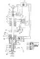
以下、従来の電子部品装着装置について、図7を参照しながら説明する。図7において、電子部品装着装置は、電子部品を吸着するノズルを備えた装着ヘッド部51と、電子部品をノズルにて吸着するための吸引装置52と、装着ヘッド部51をX,Y方向に移動させるXYロボット53と、装着ヘッド部51、吸引装置52及びXYロボット53の動作制御を行う制御装置54とを備えている。なお、図7においては、装着ヘッド部51の主要な構成部品のみを示し、例えばボディ部等の図示を省略している。
【0004】
55はスプラインシャフトで、その軸芯方向に移動可能に2つのナット56、57が嵌合して取付けられ、これらナット56、57がベアリング58、59を介して装着ヘッド部51のボディ部(図示せず)に支持されている。これによって、スプラインシャフト55は軸芯方向に移動可能にかつ軸芯回りに回転可能であり、装着ヘッド部51に装着されたモータ60によってプーリ61、ベルト62、プーリ63を介して回転駆動される。
【0005】
スプラインシャフト55の先端部55aには、電子部品64を吸着するノズル65が設けられている。このノズル65の内部には吸引時にゴミの侵入を防ぐためのフィルタ66を備えている。また、スプラインシャフト55は、周方向に摺動可能なベアリング67を介して圧縮ばね68により上方に押し上げられており、ボイスコイルモータ69の加圧力によりスプラインシャフト55、即ちノズル65が下降して電子部品64の吸着、装着作業を行うように構成されている。
【0006】
以上の構成の部品装着装置の動作を説明すると、制御装置54の制御動作によりXYロボット53が動作して装着ヘッド部51が電子部品の吸着場所である部品吸着位置に移動される。そして、ボイスコイルモータ69が制御装置54の制御により駆動され、圧縮ばね68が圧縮されることにより、スプラインシャフト55を介してノズル65が下降し、かつ吸引装置52を駆動してノズル65に電子部品64を吸着させる。次に、ボイスコイルモータ69によりノズル65を上昇させる。次に、再びXYロボット53を駆動し、電子回路基板上の部品装着位置まで装着ヘッド部51を移動させた後、再びボイスコイルモータ69によりノズル65を下降させ、電子部品64を電子回路基板上に装着する。また、電源オフ時及び停電時にはボイスコイルモータ69の加圧力がオフとなるため、圧縮ばね68のベアリング67を上方へ押し上げる力によりスプラインシャフト55、即ちノズル65の落下を防ぐことができる。
【0007】
【発明が解決しようとする課題】
しかしながら、上記のような構成では、圧縮ばね68の力によりスプラインシャフト55を上方に押し上げているため、ボイスコイルモータ69の加圧力は圧縮ばね68の力より強い力にしなければならないため、装着加圧の圧力制御が正確にできないという問題があった。またそれに伴って必要以上のボイスコイルモータ69の能力が必要となり、ボイスコイルモータ69、即ち装着ヘッド部51自体が大きくなるという問題があった。また、圧縮ばね68の圧縮による変化を小さくするため、圧縮ばね68のスペースを充分にとる必要があり、装着ヘッド部51が上下方向に大きくなるという問題があった。
【0008】
本発明は、上記従来の問題点に鑑み、圧縮ばねによる付勢力にてノズルを押し上げることなく、簡単でコンパクトな構成で電源オフ時や停電時にノズルが落下するのを防止することができ、コンパクトなボイスコイルモータにて精度良く加圧制御できる部品装着装置のノズル落下防止装置を提供することを目的としている。
【0009】
【課題を解決するための手段】
本発明の部品装着装置のノズル落下防止装置は、上下移動及び回転動作可能な外周が円形のシャフト先端に設けたノズルで部品供給部から供給された部品を吸着保持し基板上に移動して部品を装着する装着ヘッド部を備えた部品装着装置において、前記シャフトを上下方向に駆動するシャフト駆動手段と、前記シャフトを回転方向に駆動するシャフト回転手段と、一端部を支点にして開閉揺動可能でかつ中間部が前記シャフトの外周面に略沿う形状からなる把持部を成しこの把持部により前記シャフトを挟持するように付勢手段により閉方向に付勢された一対の第1レバーと、前記一対の第1レバーの他端部に設けた開閉端と、前記第1レバーの開閉端に係合して第1レバーを開く解放ピンと、解放ピンを第1レバーの開閉端に向けて駆動する第2レバーと、第2レバーをその解放ピンの駆動方向と逆方向に付勢するばねとを備え、装着ヘッド部の動作時に第2レバーを駆動して解放ピンにより第1レバーを開き、作業終了時に第2レバーの駆動を解放してシャフトを保持するようにしたものであり、装着ヘッド部の動作時にシャフトの上下移動及び回転動作が完全に自由であるためコンパクトなシャフト駆動手段にて精度良く加圧制御できるとともに、シャフト回転手段にて回転位置決めでき、かつ作業終了時に第1レバーにてシャフトを保持して確実にノズルの落下を防止することができ、停電時に制御動作が効かなくなってもばねにて確実にノズルの落下を防止することができ、機械の破損を防止できて高信頼性を実現できる。
【0010】
また、第2レバーを解放ピンの駆動方向と逆方向に付勢するばねを設ける代わりに、第2レバーを解放ピン駆動方向及び駆動方向と逆方向に往復移動させる往復移動手段を設け、装着ヘッド部の動作時にシャフト駆動手段の作動後に第2レバーを移動して解放ピンにより第1レバーを開き、作業終了時に第2レバーを逆方向に移動してシャフトを上下方向に保持するようにすることもできる。この場合、第2レバーが駆動方向と逆方向にばねで付勢されていないので、第2レバーを開放ピン駆動方向に移動する際の応答性が良くなり、駆動方向とその逆方向の両方の応答性が高くなり、高速実装動作を実現できる。往復移動手段として複動エアシリンダ装置を用いると、エア源と電磁弁の簡単な構成によって第2レバーを高速移動することができる。
【0011】
また、一対の第1レバーに前記支点と中間部の把持部と他端部の開閉端とを順に設け、他端部近傍に付勢手段を設けるのが好ましい。また、複数のノズルを直線上に備えた装着ヘッド部において、前記複数のノズルの各々の第1レバーの開閉端を直線上に揃え、これらの開閉端に係合するように複数の解放ピンを第2レバーに直線上に配置し、この第2レバーの作動にて前記複数の解放ピンを前記複数の開閉端に同時に係合させるようにすると、複数のシャフトを一括して上下方向に保持し、ノズルの落下を防止することができる。
【0012】
また、本発明の部品装着方法は、上下動及び回転動作可能な外周が円形のシャフトの下端に設けたノズルにて供給された部品を吸着保持し基板上に移動して部品を装着する部品装着方法において、常時はシャフトを把持固定し、供給された部品を吸着保持し基板上に移動して部品を装着する際にシャフトの把持を解除してシャフトを上下及び回転させるものであり、部品装着時にシャフトの上下移動及び回転動作が完全に自由であるためコンパクトな上下動駆動手段にて精度良く加圧制御できるとともに、回転位置決めできる。
【0013】
また、本発明の部品装着装置は、上下動及び回転動作可能な外周が円形のシャフトと、シャフトの下端に取付けられて部品供給部から供給される部品の吸着及び基板上に移動して部品の装着を行うノズルと、前記シャフトを所定位置で把持固定する把持手段と、前記シャフトを上下移動させるシャフト駆動手段と、前記シャフトを回転方向に駆動するシャフト回転手段と、前記把持手段によるシャフトの把持を解除する把持解除手段とを備え、常時は前記シャフトを前記把持手段により把持固定し、前記供給された部品を吸着保持し基板上に移動して部品を装着する際には前記把持手段によるシャフトの把持を前記把持解除手段にて解除してシャフトを上下及び回転させるものであり、上記部品装着方法を実行してその効果を発揮できる。
【0014】
また、その把持手段を開閉揺動可能でかつシャフトを挟持するように閉方向に付勢された一対の第1レバーにて構成し、把持解除手段を第1レバーの開閉端に係合して第1レバーを開く解放ピンと解放ピンを部品の吸着及び装着時のみ第1レバーの開閉端に向けて駆動する手段とから構成することにより、簡単な構成で確実にシャフトの把持及び把持解除を行うことができる。
【0015】
【発明の実施の形態】
以下、本発明の部品装着装置及びそのノズル落下防止装置の一実施形態について、図1〜図5を参照して説明する。
【0016】
図1において、電子回路基板1は搬送部2にて搬入、搬出され、また生産時には所定位置で保持される。3及び4はともに電子回路基板1に装着する電子部品を収納し、供給する電子部品供給部であり、電子部品供給部3は電子部品をリールに収めたリール式の電子部品供給部であり、電子部品供給部4は電子部品をトレイに収めたトレイ式の電子部品供給部である。
【0017】
5は、電子部品を吸着するノズル6の昇降、回転動作を行う装着ヘッド部であり、この装着ヘッド部5をX,Y方向に移動させるXYロボット7に装着されている。電子部品の吸着時には、XYロボット7にて装着ヘッド部5、即ちノズル6を、電子部品供給部3又は4における電子部品保持位置へ移動させた後、ノズル6を下降して電子部品を吸着し、吸着後にノズル6を上昇させる。
【0018】
ノズル6による電子部品の吸着状況は、部品認識カメラ8にて撮像され、その撮像情報に基づいて電子回路基板1への装着前に電子部品の吸着角度の補正等の要否が判断される。ノズル6に吸着された電子部品はXYロボット7による装着ヘッド部5の移動によりX,Y方向に移動されて電子回路基板1上の所定位置まで移動される。そして、装着ヘッド部5の動作によりノズル6が下降し、電子回路基板1上の所定の部品装着位置へ電子部品を装着し、電子部品の吸着を解除する。以上の動作を繰り返すことで、各電子部品が電子部品供給部3又は4から電子回路基板1上へ装着される。
【0019】
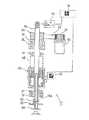
図2に、装着ヘッド部5の詳細構成、及びXYロボット7、ノズル6にて電子部品を吸着するための吸引装置9、及び装着ヘッド部5とXYロボット7と吸引装置9の動作制御を行う制御装置10とを示す。なお、図2で、便宜上、XYロボット7にて直接スプラインシャフト11を駆動するように図示しているが、実際にはXYロボット7にて装着ヘッド部5が移動されるものである。
【0020】
装着ヘッド部5において、スプラインシャフト11にはその軸芯方向に移動可能に2つのナット12、13が嵌合され、これらのナット12、13がベアリング14、15を介して装着ヘッド部5のボディ部(図示せず)に支持されている。これによって、スプランイシャフト11は軸芯方向に移動可能にかつ軸芯回りに回転可能に支持され、装着ヘッド部5に装着されたモータ16によってプーリ17、ベルト18、プーリ19を介して回転駆動される。
【0021】
スプラインシャフト11の先端部11aには、電子部品20を吸着するノズル6が設けられている。このノズル6の内部には吸引時にゴミの侵入を防ぐためのフィルタ21を備えている。そして、スプラインシャフト11を昇降駆動するボイスコイルモータ22が設けられ、ボイスコイルモータ22にてスプラインシャフト11、即ちノズル6を昇降移動させて電子部品20の吸着、装着作業を行うように構成されている。
【0022】
また、図2、図3に示すように、スプラインシャフト11をロック把持及び解放する一対の第1レバー23がボイスコイルモータ22の上部に配設されている。一対の第1レバー23は、その一端部が支点ピン24を支点にして開閉揺動可能に枢支され、中間部のスプラインシャフト11の把持部にはウレタンゴム25が設けられ、他端部には常時これら第1レバー23を閉じる方向に付勢してスプラインシャフト11をロック把持するようにスプリングシャフト26と圧縮ばね27が設けられ、さらに他端縁の互いに対向する角部に解放溝28が形成されている。
【0023】
そして、図2〜図4に示すように、ピンシリンダ29にてボールプランジャ30を介してブラケット31を揺動操作することにより、複数のスプラインシャフト11の配列方向に沿って延設された第2レバー32を動作させるように構成されている。第2レバー32には、各スプラインシャフト11毎に配設された第1レバー23に対応して解放ピン33が固定されており、第2レバー32の動作によって各解放ピン33がそれぞれに対向する解放溝28に嵌入係合して第1レバー23が開き、スプラインシャフト11はボイスコイルモータ22にて昇降駆動可能な状態となる。ブラケット31は引張ばね34にて常時解放ピン33を解放溝28から離脱させる方向に揺動付勢されている。
【0024】
なお、図2において、22aはボイスコイルモータ22のケーシング、35はボイスコイル、36はマグネットである。また、吸引装置9と、スプラインシャフト11にノズル6に連通するように形成された中空穴37とが、エアジョイント38、ボイスコイルモータ22のケーシング22aに形成された連通穴39、スプラインシャフト11に形成された連通穴40を通して連通されている。また、スプラインシャフト11の上端部11bには磁気スケール41が設けられ、磁気センサ42にてスプラインシャフト11の昇降位置を検出できるように構成され、さらに透過センサ43による磁気スケール41の上端の検出にてスプラインシャフト11の原点位置を検出するように構成されている。
【0025】
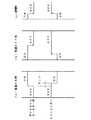
以上の構成の部品装着装置の動作を説明すると、図5(a)に示すように、電源がONされてボイスコイルモータ22のサーボがONとなると、必ず一定のディレイの後にピンシリンダ29がオンされるように構成されており、その後部品吸着、装着動作に入ることができる。
【0026】
まず、制御装置10の制御動作によりXYロボット7が動作して装着ヘッド部5が電子部品の吸着場所である部品吸着位置に移動される。そして、制御装置10の制御によりピンシリンダ29が駆動され、ブラケット31に固定されたボールプランジャ30を下方に押し下げることにより第2レバー32に複数個取付けられた解放ピン33が第1レバー23の解放溝28に嵌入係合して第1レバー23が圧縮ばね27に抗して開かれ、第1レバー23のウレタンゴム25がスプラインシャフト11から離間する。そして、スプラインシャフト11がボイスコイルモータ22にて下降されることによりノズル6が下降し、かつ吸引装置9を駆動してノズル6に電子部品20を吸着させる。
【0027】
次に、ボイスコイルモータ22によりノズル6を上昇させる。次に、再びXYロボット7を駆動し、電子回路基板上の部品装着位置まで装着ヘッド部5を移動させた後、再びボイスコイルモータ22によりノズル6を下降させ、電子部品20を電子回路基板上に装着する。
【0028】
そして、一連動作が終了すると、制御装置10の制御によりピンシリンダ29が駆動され、先程下方に押し下げていたボールプランジャ30を上方に引き戻すことにより第2レバー32に複数個取付けられた解放ピン33が第1レバー23の解放溝28から離れ、第1レバー23が圧縮ばね27にて閉じられ、ウレタンゴム25を介してスプラインシャフト11がロック把持される。
【0029】
また、電源OFF時には、図5(b)に示すように、ボイスコイルモータ22のサーボOFFに先立ってピンシリンダ29がOFF状態とされる。また、緊急停電時には、図5(c)に示すように、制御装置10からの制御動作が効かなくなるため、ボイスコイルモータ22によりスプラインシャフト11が支持されないので、スプラインシャフト11、即ちノズル6が自重により落下するが、ブラケット31に取付けられた引張ばね34により瞬時にブラケット31に固定されたボールプランジャ30を上方に引き戻すことにより、第2レバー32に複数個取付けられた解放ピン33が第1レバー23の解放溝28から離れ、解放されていた第1レバー23が圧縮ばね27により閉じられ、スプラインシャフト11がウレタンゴム25を介してロック把持される。なお、ピンシリンダ29のOFF時のボールプランジャ30を押し下げる力よりも引張ばね34の引張力の方が強いため、停電時でもスプラインシャフト11を瞬時に把持することができる。
【0030】
次に、本発明の他の実施形態について説明する。上記実施形態ではブラケット31を解放ピン33駆動方向に移動するのにピンシリンダ29を、駆動方向と逆方向に復帰移動するのに引張ばね34を用いた例を示したが、本実施形態では図6に示すように、複動シリンダ45を用いている。この複動シリンダ45は制御装置10からの信号にて電磁弁46がオンすることよってエア源49からエアチューブ50を通して供給された圧縮エアが導入されるシリンダ室が切り換えられてシリンダシャフト45aが伸展するように構成され、制御装置10からの信号が停止すると電磁弁46がオフすることによってエア源49からエアチューブ50を通して供給された圧縮エアが導入されるシリンダ室が切り換えられてシリンダシャフト45aが退入するように構成されている。
【0031】
シリンダシャフト45aの先端には、ブラケット31の側面に接触する連結ブロック47が固定されている。連結ブロック47にはその移動方向と直交する方向に長孔47aが形成され、ブラケット31の先端部の側面に突設された連結ピン48が嵌入係合されている。なお、ブラケット31の基端部に設けられた固定穴31aに第2レバー32の端部が固定されている。かくして、シリンダシャフト45aが退入位置にある状態ではブラケット31が上方揺動して解放ピン33が解放溝28から離脱してスプラインシャフト11がロック把持され、逆にシリンダシャフト45aが伸展位置にある状態ではブラケット31が下方揺動して解放ピン33が解放溝28に嵌入係合して第1レバー23が開かれ、スプラインシャフト11のロックが解除される。
【0032】
上記実施形態の場合には応答性良くスプラインシャフト11をロック把持するために引張ばね34の付勢力を大きくすると、第2レバー32を開放ピン33駆動方向に移動させてスプラインシャフト11を解放する際に引張ばね34の付勢力に逆らうために応答性が悪くなるが、本実施形態によれば第2レバー32を開放ピン33駆動方向に移動する際に引張ばね34の付勢力に抗して移動させる必要がないので応答性が良くなり、逆方向の場合も複動シリンダ45にて応答性良く動作するため、両方の応答性を高くでき、高速実装動作を実現することができる。
【0033】
【発明の効果】
本発明の部品装着装置のノズル落下防止装置によれば、以上の説明から明らかなように、装着ヘッド部の動作時に第2レバーを駆動して解放ピンにより第1レバーを開き、作業終了時に第2レバーの駆動を解放してシャフトを保持するようにしたものであり、装着ヘッド部の動作時にシャフトの上下移動及び回転動作が完全に自由であるためコンパクトなシャフト駆動手段にて精度良く加圧制御できるとともに、シャフト回転手段にて回転位置決めでき、かつ作業終了時に第1レバーにてシャフトを保持して確実にノズルの落下を防止することができ、停電時に制御動作が効かなくなってもばねにて確実にノズルの落下を防止することができ、機械の破損を防止できて高信頼性を実現できる。
【0034】
また、第2レバーを解放ピンの駆動方向と逆方向に付勢するばねを設ける代わりに、第2レバーを解放ピン駆動方向及び駆動方向と逆方向に往復移動させる往復移動手段を設けると、第2レバーが駆動方向と逆方向にばねで付勢されていないので、第2レバーを開放ピン駆動方向に移動する際の応答性が良くなり、駆動方向とその逆方向の両方の応答性が高くなり、高速実装動作を実現できる。
【0035】
また、一対の第1レバーに前記支点と中間部の把持部と他端部の開閉端とを順に設け、他端部近傍に付勢手段を設けるのが好ましい。
【0036】
また、複数のノズルを直線上に備えた装着ヘッド部において、前記複数のノズルの各々の第1レバーの開閉端を直線上に揃え、これらの開閉端に係合するように複数の解放ピンを第2レバーに直線上に配置し、この第2レバーの作動にて前記複数の解放ピンを前記複数の開閉端に同時に係合させるようにすると、複数のシャフトを一括して上下方向に保持し、ノズルの落下を防止することができる。
【0037】
また、本発明の部品装着方法によれば、上下動及び回転動作可能な外周が円形のシャフトの下端に設けたノズルにて供給された部品を吸着保持し基板上に移動して部品を装着する部品装着方法において、常時はシャフトを把持固定し、供給された部品を吸着保持し基板上に移動して部品を装着する際にシャフトの把持を解除してシャフトを上下及び回転させるものであり、部品装着時にシャフトの上下移動及び回転動作が完全に自由であるためコンパクトな上下動駆動手段にて精度良く加圧制御できるとともに、回転位置決めできる。
【0038】
また、本発明の部品装着装置によれば、上下動及び回転動作可能な外周が円形のシャフトと、シャフトの下端に取付けられて部品供給部から供給される部品の吸着及び基板上に移動して部品の装着を行うノズルと、前記シャフトを所定位置で把持固定する把持手段と、前記シャフトを上下移動させるシャフト駆動手段と、前記シャフトを回転方向に駆動するシャフト回転手段と、前記把持手段によるシャフトの把持を解除する把持解除手段とを備え、常時は前記シャフトを前記把持手段により把持固定し、前記供給された部品を吸着保持し基板上に移動して部品を装着する際には前記把持手段によるシャフトの把持を前記把持解除手段にて解除してシャフトを上下及び回転させるものであるので、上記部品装着方法を実行してその効果を発揮できる。
【0039】
また、その把持手段を開閉揺動可能でかつシャフトを挟持するように閉方向に付勢された一対の第1レバーにて構成し、把持解除手段を第1レバーの開閉端に係合して第1レバーを開く解放ピンと解放ピンを部品の吸着及び装着時のみ第1レバーの開閉端に向けて駆動する手段とから構成することにより、簡単な構成で確実にシャフトの把持及び把持解除を行うことができる。
【図面の簡単な説明】
【図1】本発明の部品装着装置のノズル落下防止装置の一実施形態における部品装着装置の全体概略構成を示す斜視図である。
【図2】同実施形態における装着ヘッド部の概略構成を示す部分縦断面図である。
【図3】同実施形態における要部の構成を示す平面図である。
【図4】同実施形態における要部の構成を示す側面図である。
【図5】同実施形態におけるスプラインシャフトロック用ピンシリンダの動作タイミング図である。
【図6】本発明の部品装着装置のノズル落下防止装置の他の実施形態における要部の構成を示し、(a)は斜視図、(b)は(a)のA部側面図、(c)は(b)のB−B矢視図である。
【図7】従来例の部品装着装置における装着ヘッド部の概略構成を示す部分縦断面図である。
【符号の説明】
5 装着ヘッド部
6 ノズル
11 スプラインシャフト
20 電子部品
22 ボイスコイルモータ(シャフト駆動手段)
23 第1レバー
28 解放溝
32 第2レバー
33 解放ピン
34 引張ばね
45 複動シリンダ[0001]
BACKGROUND OF THE INVENTION
The present invention relates to a component mounting apparatus applied to, for example, mounting of electronic components on an electronic circuit board, and more particularly to a nozzle fall prevention device in a mounting head portion provided with a nozzle that sucks components.
[0002]
[Prior art]
In recent years, as leadless electronic components (chip components) have become widespread, the types of shapes and sizes thereof have become various. Moreover, in an electronic component mounting apparatus for mounting these electronic components, high speed, high accuracy, high productivity, and high reliability are required.
[0003]
Hereinafter, a conventional electronic component mounting apparatus will be described with reference to FIG. In FIG. 7, the electronic component mounting apparatus includes a
[0004]
55 is a spline shaft, and two
[0005]
A
[0006]
The operation of the component mounting apparatus having the above configuration will be described. The XY
[0007]
[Problems to be solved by the invention]
However, in the configuration as described above, the spline shaft 55 is pushed upward by the force of the compression spring 68, and therefore the pressure force of the voice coil motor 69 must be stronger than the force of the compression spring 68. There was a problem that the pressure control of the pressure could not be performed accurately. Along with this, there is a problem in that the capacity of the voice coil motor 69 is more than necessary, and the voice coil motor 69, that is, the
[0008]
In view of the above-described conventional problems, the present invention can prevent the nozzle from dropping at the time of power-off or power failure with a simple and compact configuration without pushing up the nozzle by the urging force of the compression spring, and is compact. It is an object of the present invention to provide a nozzle drop prevention device for a component mounting device that can accurately control pressure with a simple voice coil motor.
[0009]
[Means for Solving the Problems]
The nozzle drop prevention device of the component mounting device according to the present invention isconfigured to suck andholda componentsupplied from a component supply unit bya nozzleprovided at the tipof acircular shaft whoseouter periphery can be moved upand downand rotated and moved onto asubstrate. in the component mounting apparatus having a mounting head section for mounting anda shaft driving means for drivingthe shaft in the vertical direction,a shaft rotating means for driving said shaft in the rotational direction, that openswings the one end portion to the fulcrum And a pair of first levers biased in a closing directionby a biasing means so that theintermediate portionforms a grip portion having a shape substantially along the outer peripheral surface of the shaft, and theshaft is sandwichedby the grip portion .An opening / closing end provided at the other end of the pair of first levers, a release pin that engages with the opening / closing end of the first lever and opens the first lever, and the release pin is driven toward the opening / closing end of the first lever You A second lever, and a spring for biasing the driving direction opposite to the direction of the release pin a second lever, opens the first lever by the release pin of thesecond lever is drivenduring operation of the mounting head section,a shaft to release the driving of the second lever at the end of work is obtained by so as tohold, in a compact shaft driving means for vertically movingand rotating operation of the shaft during operation of the mounting head unit is completely free accuracy can pressurization control TeRutotomoni can be rotated positioned by the shaft rotation means, and it is possible to reliably prevent drop of the nozzle while holding the shaft in the first lever at the end of work, the control operation in case of power failure Even if it is not effective, the spring can surely prevent the nozzle from falling, and the machine can be prevented from being damaged and high reliability can be realized.
[0010]
Further, instead of providing a spring for urging the second lever in the direction opposite to the driving direction of the release pin, a reciprocating means for reciprocating the second lever in the direction opposite to the driving direction of the release pin and the driving direction is provided. The second lever is moved after the shaft driving means is actuated during operation of the part and the first lever is opened by the release pin, and the second lever is moved in the opposite direction when the operation is completed to hold the shaft in the vertical direction. You can also. In this case, since the second lever is not biased by the spring in the direction opposite to the driving direction, the response when moving the second lever in the opening pin driving direction is improved, and both the driving direction and the opposite direction are improved. High responsiveness and high-speed mounting operation can be realized. When a double-action air cylinder device is used as the reciprocating means, the second lever can be moved at high speed with a simple configuration of an air source and a solenoid valve.
[0011]
Further, it is preferable that the pair of first levers are provided with the fulcrum, an intermediate gripping portion, and an opening / closing end of the other end portion in order, and an urging means is provided inthe vicinity of the other end portion. In addition, in the mounting head portion provided with a plurality of nozzles on a straight line, the open / close ends of the first levers of the plurality of nozzles are aligned on a straight line, and a plurality of release pins are provided so as to engage with the open / close ends. If the second lever is arranged in a straight line and the plurality of release pins are simultaneously engaged with the plurality of open / close ends by the operation of the second lever, the plurality of shafts are collectively held in the vertical direction. The nozzle can be prevented from falling.
[0012]
In addition, the component mounting method of the present invention is a component mountingin which a componentsupplied bya nozzleprovided at the lower end ofa shafthaving a circular outer periphery that can be moved upand downand rotated is sucked andheld on asubstrate and mounted. in the method, which normally grips fixed to the shaft, it isvertically and rotating thesheet Yafutoto release the grip on thesheet Yafutowhen mountingthe component thesupplied partto move the suctionholdingsubstrate, Since the vertical movementand rotation of the shaft are completely free when the parts are mounted, the pressure can be controlledwith high precision by a compact vertical movement drive means, and the rotation can be positioned .
[0013]
In addition, the component mounting device of the present inventionhas a shaft with acircular outer periphery that can be moved upand downand rotated ,and is attached to the lower end ofthe shaft and sucks thecomponent supplied from thecomponent supply unitand moves onto thesubstrate to move the component. a nozzle that performs mounting and grip means for gripping fixingthe shaft in a predetermined position, a shaft driving means for vertically movingthe shaft,the shaft rotating means for driving said shaft in the rotational direction, the gripping of the shaft bysaid gripping means A grip release means for releasing theshaft, and the shaft is normally held and fixed by the grip means, and when the supplied component is sucked and held and moved onto the substrate to mount the component, the shaft by the grip means The grip is released by the grip release means and the shaft is moved up and down and rotated , and the effect can be exhibited by executing the component mounting method.
[0014]
The gripping means is composed of a pair of first levers that can be opened and closed and biased in the closing direction so as to sandwich the shaft, and the grip release means is engaged with the opening and closing ends of the first lever. By constituting the release pin for opening the first lever and the means for driving the release pin toward the opening / closing end of the first lever only when the parts are attracted and mounted, the shaft can be reliably grasped and released with a simple structure. be able to.
[0015]
DETAILED DESCRIPTION OF THE INVENTION
Hereinafter, an embodiment of a component mounting device and a nozzle drop prevention device of the present invention will be described with reference to FIGS.
[0016]
In FIG. 1, an electronic circuit board 1 is carried in and out by a
[0017]
[0018]
The suction state of the electronic component by the
[0019]
2, the detailed configuration of the mounting
[0020]
In the mounting
[0021]
A
[0022]
As shown in FIGS. 2 and 3, a pair of
[0023]
As shown in FIGS. 2 to 4, the
[0024]
In FIG. 2, 22a is a casing of the
[0025]
The operation of the component mounting apparatus having the above configuration will be described. As shown in FIG. 5A, when the power is turned on and the servo of the
[0026]
First, the XY robot 7 is operated by the control operation of the
[0027]
Next, the
[0028]
When the series of operations is completed, the
[0029]
When the power is turned off, as shown in FIG. 5B, the
[0030]
Next, another embodiment of the present invention will be described. In the above embodiment, the
[0031]
A connecting
[0032]
In the case of the above embodiment, when the urging force of the
[0033]
【The invention's effect】
According to the nozzle drop prevention device of the component mounting device of the present invention, as is clear from the above description, the second lever is driven when the mounting head portion is operated,and the first lever is opened by the release pin. are those in whicha shaft to release the driving of the second lever so as toretain, accurately in a compact shaft driving means for vertically movingand rotating operation of the shaft during operation of the mounting head unit is completely free pressurization can controlRutotomoni can be rotated positioned by the shaft rotation means, and work end at the first lever holding the shaft can be prevented reliably drop nozzle at, may not work correctly controlled operation in case of power failure Also, the spring can reliably prevent the nozzle from falling, and the machine can be prevented from being damaged to achieve high reliability.
[0034]
In addition, instead of providing a spring that biases the second lever in the direction opposite to the driving direction of the release pin, if a reciprocating means for reciprocating the second lever in the direction opposite to the driving direction of the release pin and the driving direction is provided, Since the two levers are not biased by the spring in the direction opposite to the driving direction, the response when moving the second lever in the opening pin driving direction is improved, and the response in both the driving direction and the opposite direction is high. Thus, high-speed mounting operation can be realized.
[0035]
Further, it is preferable that the pair of first levers are provided with the fulcrum, an intermediate gripping portion, and an opening / closing end of the other end portion in order, and an urging means is provided inthe vicinity of the other end portion.
[0036]
In addition, in the mounting head portion provided with a plurality of nozzles on astraight line,the open / close ends of the first levers of the plurality of nozzles are aligned on a straight line, and a plurality of release pins are provided so as to engage with the open / close ends. If the second lever is arranged in a straight line and the plurality of release pins are simultaneously engaged with the plurality of open / close ends by the operation of the second lever , the plurality of shafts are collectively held in the vertical direction. The nozzle can be prevented from falling.
[0037]
Further, according to the component mounting method of the present invention, the componentsupplied bythe nozzleprovided at the lower end ofthe shafthaving a circular outer periphery that canmove upand downand rotate is sucked andheld on thesubstrate to mount thecomponent . in component mounting method, always grips fixed shaft, in which to release the grip of thesheet Yafutovertical and rotating thesheet Yafutoandwhen mountingthe component thesupplied partto move the suctionholdingsubstrate In addition, since the vertical movementand rotation of the shaft are completely free when the parts are mounted, the pressure can be controlledwith high precision by a compact vertical movement driving means, and the rotation can be positioned .
[0038]
Further, according to the component mounting apparatus of the present invention, theouter periphery that can be moved upand downand rotated is attached to thecircular shaft, and thecomponent attached to the lower end ofthe shaft is sucked andmoved onto thesubstrate. a nozzle that performscomponent mountingof a gripping means for gripping fixingthe shaft in a predetermined position, a shaft driving means for vertically movingthe shaft,the shaft rotating means for driving said shaft in the rotational direction, the shaft bythe gripping means Gripping release means for releasing the gripping of the gripper, the gripping means isnormally held and fixed by the gripping means, and the gripping means is used when the supplied component is sucked and held and moved onto the substrate to mount the component. since thosefor vertical and rotate the shaft to release the grip of the shaft at the gripping releasing unit by, exert their effects by performing the above-described component mounting method Kill.
[0039]
Further, the gripping means is constituted by a pair of first levers that can be opened and closed and biased in the closing direction so as to sandwich the shaft, and the grip release means is engaged with the opening and closing ends of the first lever. By constituting the release pin for opening the first lever and the means for driving the release pin toward the opening / closing end of the first lever only when the component is sucked and mounted, the shaft can be reliably grasped and released with a simple structure. be able to.
[Brief description of the drawings]
FIG. 1 is a perspective view showing an overall schematic configuration of a component mounting device according to an embodiment of a nozzle drop prevention device of a component mounting device of the present invention.
FIG. 2 is a partial longitudinal sectional view showing a schematic configuration of a mounting head portion in the same embodiment.
FIG. 3 is a plan view showing a configuration of a main part in the same embodiment.
FIG. 4 is a side view showing a configuration of a main part in the same embodiment.
FIG. 5 is an operation timing chart of the spline shaft locking pin cylinder in the same embodiment;
6A and 6B show the structure of the main part of another embodiment of the nozzle drop prevention device of the component mounting device of the present invention, wherein FIG. 6A is a perspective view, FIG. 6B is a side view of the A part of FIG. ) Is a BB arrow view of (b).
FIG. 7 is a partial longitudinal sectional view showing a schematic configuration of a mounting head portion in a conventional component mounting apparatus.
[Explanation of symbols]
5 Mounting
23
Claims (7)
Translated fromJapanesePriority Applications (1)
| Application Number | Priority Date | Filing Date | Title |
|---|---|---|---|
| JP24667098AJP3748718B2 (en) | 1997-09-29 | 1998-09-01 | Nozzle fall prevention device for component mounting device |
Applications Claiming Priority (3)
| Application Number | Priority Date | Filing Date | Title |
|---|---|---|---|
| JP26468797 | 1997-09-29 | ||
| JP9-264687 | 1997-09-29 | ||
| JP24667098AJP3748718B2 (en) | 1997-09-29 | 1998-09-01 | Nozzle fall prevention device for component mounting device |
Publications (2)
| Publication Number | Publication Date |
|---|---|
| JPH11163598A JPH11163598A (en) | 1999-06-18 |
| JP3748718B2true JP3748718B2 (en) | 2006-02-22 |
Family
ID=26537846
Family Applications (1)
| Application Number | Title | Priority Date | Filing Date |
|---|---|---|---|
| JP24667098AExpired - Fee RelatedJP3748718B2 (en) | 1997-09-29 | 1998-09-01 | Nozzle fall prevention device for component mounting device |
Country Status (1)
| Country | Link |
|---|---|
| JP (1) | JP3748718B2 (en) |
Families Citing this family (2)
| Publication number | Priority date | Publication date | Assignee | Title |
|---|---|---|---|---|
| JP5201483B2 (en)* | 2009-05-26 | 2013-06-05 | 株式会社日立ハイテクインスツルメンツ | Electronic component mounting device |
| CN103209548B (en)* | 2013-03-26 | 2015-10-28 | 芜湖齐创自动化系统有限公司 | A kind of SMT mounting device suction nozzle module and control method thereof |
- 1998
- 1998-09-01JPJP24667098Apatent/JP3748718B2/ennot_activeExpired - Fee Related
Also Published As
| Publication number | Publication date |
|---|---|
| JPH11163598A (en) | 1999-06-18 |
Similar Documents
| Publication | Publication Date | Title |
|---|---|---|
| US6591493B1 (en) | Method of preventing a nozzle drop in a component mounting apparatus | |
| JPH0369650B2 (en) | ||
| JP3652397B2 (en) | Component mounting method and mounting device | |
| JP3748718B2 (en) | Nozzle fall prevention device for component mounting device | |
| JP6047239B2 (en) | Component suction nozzle and component mounting device | |
| JP4504308B2 (en) | DIE PICKUP METHOD AND DIE PICKUP DEVICE | |
| JP6571201B2 (en) | Component mounting method | |
| JP2006337043A (en) | Appearance inspection device | |
| JP3942217B2 (en) | Electronic component mounting apparatus and electronic component mounting method | |
| KR102062278B1 (en) | Chip mounter | |
| JP2712458B2 (en) | Component adsorption method and component adsorption element | |
| JP3901804B2 (en) | Component mounting head and component mounting device | |
| JP3931215B2 (en) | Conductive ball mounting device | |
| JP2625948B2 (en) | Electronic component mounting apparatus and electronic component mounting method | |
| JPH0688227B2 (en) | Component mounting method and device | |
| JPH06188595A (en) | Electronic part mounting device | |
| JP3231371B2 (en) | Chip mounting method | |
| JP4021598B2 (en) | Surface mount component mounting machine | |
| JPH01220500A (en) | Component positioning transfer head and component transfer method using the head | |
| JPH01187898A (en) | Article transfer method and its equipment | |
| JP3044901B2 (en) | Electronic component mounting equipment | |
| JPH0521997A (en) | Electronic-part moving and mounting head | |
| JP2003078290A (en) | Apparatus and method for component mounting | |
| JP2629308B2 (en) | Component suction insertion jig | |
| JP3013115B2 (en) | Method and apparatus for removing and moving plate-like object |
Legal Events
| Date | Code | Title | Description |
|---|---|---|---|
| A977 | Report on retrieval | Free format text:JAPANESE INTERMEDIATE CODE: A971007 Effective date:20050426 | |
| A131 | Notification of reasons for refusal | Free format text:JAPANESE INTERMEDIATE CODE: A131 Effective date:20050510 | |
| A521 | Written amendment | Free format text:JAPANESE INTERMEDIATE CODE: A523 Effective date:20050707 | |
| A131 | Notification of reasons for refusal | Free format text:JAPANESE INTERMEDIATE CODE: A131 Effective date:20050809 | |
| A521 | Written amendment | Free format text:JAPANESE INTERMEDIATE CODE: A523 Effective date:20050927 | |
| TRDD | Decision of grant or rejection written | ||
| A01 | Written decision to grant a patent or to grant a registration (utility model) | Free format text:JAPANESE INTERMEDIATE CODE: A01 Effective date:20051108 | |
| A61 | First payment of annual fees (during grant procedure) | Free format text:JAPANESE INTERMEDIATE CODE: A61 Effective date:20051129 | |
| R150 | Certificate of patent (=grant) or registration of utility model | Free format text:JAPANESE INTERMEDIATE CODE: R150 | |
| FPAY | Renewal fee payment (prs date is renewal date of database) | Free format text:PAYMENT UNTIL: 20091209 Year of fee payment:4 | |
| FPAY | Renewal fee payment (prs date is renewal date of database) | Free format text:PAYMENT UNTIL: 20091209 Year of fee payment:4 | |
| FPAY | Renewal fee payment (prs date is renewal date of database) | Free format text:PAYMENT UNTIL: 20101209 Year of fee payment:5 | |
| FPAY | Renewal fee payment (prs date is renewal date of database) | Free format text:PAYMENT UNTIL: 20101209 Year of fee payment:5 | |
| FPAY | Renewal fee payment (prs date is renewal date of database) | Free format text:PAYMENT UNTIL: 20111209 Year of fee payment:6 | |
| FPAY | Renewal fee payment (prs date is renewal date of database) | Free format text:PAYMENT UNTIL: 20111209 Year of fee payment:6 | |
| FPAY | Renewal fee payment (prs date is renewal date of database) | Free format text:PAYMENT UNTIL: 20121209 Year of fee payment:7 | |
| FPAY | Renewal fee payment (prs date is renewal date of database) | Free format text:PAYMENT UNTIL: 20121209 Year of fee payment:7 | |
| FPAY | Renewal fee payment (prs date is renewal date of database) | Free format text:PAYMENT UNTIL: 20131209 Year of fee payment:8 | |
| LAPS | Cancellation because of no payment of annual fees |