JP3748526B2 - Input device - Google Patents
Input deviceDownload PDFInfo
- Publication number
- JP3748526B2 JP3748526B2JP2001277435AJP2001277435AJP3748526B2JP 3748526 B2JP3748526 B2JP 3748526B2JP 2001277435 AJP2001277435 AJP 2001277435AJP 2001277435 AJP2001277435 AJP 2001277435AJP 3748526 B2JP3748526 B2JP 3748526B2
- Authority
- JP
- Japan
- Prior art keywords
- light
- light emitting
- timing
- imaging
- shape
- Prior art date
- Legal status (The legal status is an assumption and is not a legal conclusion. Google has not performed a legal analysis and makes no representation as to the accuracy of the status listed.)
- Expired - Fee Related
Links
Images


Landscapes
- Length Measuring Devices By Optical Means (AREA)
- Closed-Circuit Television Systems (AREA)
- Studio Devices (AREA)
Description
Translated fromJapanese【0001】
【発明の属する技術分野】
本発明は、人物の動作などを非接触に獲得する技術であって、特にその検出をより安定的に行わせるために対象人物が保持したり装着したりする入力装置および入力装置に用いる発光ターゲット装置、入力装置に用いる画像獲得装置に関する。
【0002】
【従来の技術】
人物の動作をその人物と非接触で獲得するための技術は古くより行われており、特に画像センサ(カメラ)の入力を解析することにより、その中に映っている人物の動作を獲得する技術は長く研究・開発が行われてきている。しかし、画像の持つ情報の多さ、複雑さゆえに、安定して動作情報を取り出すのは難しい。
【0003】
その現状に対し、特開平10−177449号公報において、アクティブに光を発光し、その物体反射光を画像センサで撮像することにより、背景などが除去され、対象物体のみの画像を得る手法が公開されている。これは遠い背景からの反射光の強さは、近くにある対象物体からの反射光にくらべ極めて小さくなるため、画像にほとんど映らなくなることを利用している。
【0004】
また、特開平9−243325号公報によれば、発光体を身に付け、それをCCDカメラで取得することで、光源の位置が特定でき、体の動作を取得することが出来ることが示されている。しかし、ここでは通常のカメラで動作を取得しているため、背景に窓など明るい部分が映ってしまい、検出に支障をきたす恐れがあった。また、映った光源の大きさによって距離が求められることには言及しているが、それ以外の幾何学的特徴量の取得に関しては言及されていない。
【0005】
【発明が解決しようとする課題】
特開平10−177449に示される装置を用いた場合、対象物体の距離範囲を伸ばそうとすると問題が発生する。すなわち、対象物体の距離が遠くなると、対象物体と背景との距離の比がだんだん小さくなってくる。物体からの反射光の強さは実際には距離だけでなく、物体表面の反射率などにも依存するため、それらの条件によっては、背景と対象物体との分離が難しくなる場合がある。
【0006】
基本的には、反射光の強さは物体距離の2乗に反比例するため、例えば30cmのものと60cmのものは強度が4倍違うため、その分離が容易である。しかし、1mと1m30cmの場合(同じ距離の差は30cmであるが)、強度比が1:0。6程度になるため、距離が離れるに従い背景と物体の分離が難しくなってくる。
【0007】
本願発明は、このような状況においても容易に動作を検出できるように、対象物体(この場合、多くにおいては人物)が装着したり保持したりする、補助的な発光ターゲット装置を提案するものである。またこれらの補助的な装置と連動するための画像獲得装置についても述べ、それらを組み合わせた入力装置を提案するものである。
【0008】
【課題を解決するための手段】
本願発明はタイミング信号を光または無線により発信するタイミング信号発信手段と、前記タイミング信号発信手段にて発信された前記タイミング信号を受信するタイミング信号受信手段と、前記タイミング信号受信手段にて受信したタイミング信号に対応するタイミングで発光する発光手段と、前記発光手段によって発光される光を、特定形状で拡散発光させる光拡散手段と、前記光拡散手段を介して拡散された前記発光手段による光を撮像する撮像手段と、前記撮像手段により撮像された光の形状から幾何学的特徴を検出する幾何学的特徴検出手段を具備することを特徴とする。
【0009】
また、タイミング信号を光または無線により発信するタイミング信号発信手段と、前記タイミング信号発信手段にて発信された前記タイミング信号を受信するタイミング信号受信手段と、前記タイミング信号受信手段にて受信したタイミング信号に対応するタイミングで発光する発光手段と、前記発光手段によって発光される光を、特定形状で拡散発光させる光拡散手段と、前記発光手段の発光するタイミングに関連付けられた特定の時間に発せられた光のみを撮像する撮像手段と、前記撮像手段により撮像された光の形状から幾何学的特徴を検出する幾何学的特徴検出手段を具備することを特徴とする。
【0010】
また、パルス状に光を発する発光手段と、前記発光手段によって発光される光を、特定形状で拡散発光させる光拡散手段と、前記発光手段からの発光のタイミングを検出するためのタイミング検出手段と、前記タイミング検出手段によって検出された発光のタイミングに同期し、前記発光のタイミングあるいは発光のタイミングと関連付けられた特定の時間に発光した光のみを撮像する撮像手段と、前記撮像手段により撮像された光の形状から幾何学的特徴を検出する幾何学的特徴検出手段を具備することを特徴とする。
【0011】
また、光を発する発光手段と、前記発光手段によって発光される光を、特定形状で反射させる光反射手段と、前記光反射手段から反射された光を撮像する撮像手段と、前記撮像手段により撮像された光の形状から幾何学的特徴を検出する幾何学的特徴検出手段を具備することを特徴とする。
【0012】
また、あるタイミングで発光する発光手段と、前記発光手段によって発光される光を、特定形状で反射させる光反射手段と、前記発光手段の発光するタイミングに関連付けられた特定の時間に発せられた光のみを撮像する撮像手段と、前記撮像手段により撮像された光の形状から幾何学的特徴を検出する幾何学的特徴検出手段を具備することを特徴とする。
【0013】
また、パルス状に光を発する発光手段と、前記発光手段によって発光される光を、特定形状で反射させる光反射手段と、前記発光手段からの発光のタイミングを検出するためのタイミング検出手段と、前記タイミング検出手段によって検出された発光のタイミングに同期し、前記発光のタイミングあるいは発光のタイミングと関連付けられた特定の時間に発光した光のみを撮像する撮像手段と、前記撮像手段により撮像された光の形状から幾何学的特徴を検出する幾何学的特徴検出手段を具備することを特徴とする。
【0014】
このような構成を有することにより、取得対象となる物体が遠い距離にあっても対象物体にターゲット装置を装着または保持して動作することで、対象物体の動きを確実に検出できる。
【0015】
【発明の実施の形態】
以下において、本願発明の実施例について図面を用いて説明する。
【0016】
<基本となるシステム> 図1は、本願発明が対象としている、反射光画像獲得装置の基本構成を示している。反射光画像獲得装置の詳細については、特開平10−177449号公報に詳細に記述されているため、ここでは、概要を示すのにとどめる。発光部12はLEDなどの光源により、取得対象物体14を照射する。この場合、近赤外光などを用いると対象が人物である場合に、まぶしさを感じずに済む。次に、発光部12から照射した光が対象物体に反射して戻り、光学系4を経てイメージセンサ1に結像する。
【0017】
このイメージセンサ1は、通常の画像とは異なり、発光した光の物体反射光のみが画像として取得できるような構成になっている。具体的には、短時間にLEDを発光し、発光時と、その前後の非発光時と2度の撮像を行い、その差分を取り出すことで実現する。この機能は、イメージセンサそのもの、もしくはイメージセンサとその周辺回路による制御部11により実現される。
【0018】
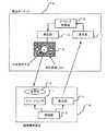
<発光ターゲット装置> 図2に、本願発明の第1の実施例に関して述べる。画像獲得装置5は、図1の画像獲得装置の構成とほぼ同じである。
【0019】
画像獲得装置5は発光部2によって、タイミング信号を発光する。発光ターゲット装置6の受光部7は、この光を受光しタイミング制御部8に伝える。タイミング制御部8では、この受光した信号から、タイミング信号を取り出し、そのタイミング信号に関連づけられたしかるべきタイミングで発光部10を発光させる。発光部10によって発光された光は光拡散板9によって特定の形状で拡散される。光拡散板9はこの光を透過させる物体と透過されない物体とから成り、特定の形状に拡散発光するように構成される。
【0020】
発光部2は、図1の発光部12と似ているが、この場合はタイミング信号を発信する手段として機能する。これは光だけではなく、無線や超音波などあらゆる無線電送手段が用いられてもよい。
【0021】
また、従来の反射光画像獲得装置をそのまま用いることもできる。それは、もともとの画像獲得装置の発光部は、広い発光指向特性を持っているため、撮像対象範囲に存在する受光部であればこれを受光することが可能であるからである。この受光するための発光ターゲットは、常に画像獲得装置に正対しているとは限らないため、拡散板などで光が拡散されることは重要である。
【0022】
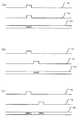
ここで、画像獲得装置5における、タイミング信号生成タイミングと、イメージセンサの撮像タイミングにはいくつかのバリエーションが考えられる。一番簡単な例は、タイミング信号の発信と同時に撮像することである。つまり、画像獲得装置5はほとんど基本のシステムと同様に動作する。発光ターゲット装置6は、受光部7でタイミングを受け取ると即座に発光を開始する。それにより若干のディレイはあっても、ほぼ発光ターゲット装置の発光部10の発光と、画像獲得装置5による撮像は同期する。これを図3(a)に示す。
【0023】
なお、図3では、タイミング発生パルスと発光ターゲットの発光パルスが同じ幅であるが、単にタイミングを与えるだけであり、発光幅が固定であるならば、必ずしもパルス幅が同じである必要はない。これは以下の他のバリエーションの場合も同じである。
【0024】
図3(a)のタイミングで動作させると、基本のシステムと全く同じ画像獲得装置5を撮像側で用いることができる。しかし、基本のシステムをそのまま用いてしまうと、取得された画像は、画像獲得装置5が発したタイミング光18の反射光と、発光ターゲット装置6による発光19との両方を含んだものになってしまう。対象物体が比較的遠い場合は影響が少ないが、近い場合は、反射光だけでもかなりの光量になってしまうので、対象物体の検出が難しくなってしまう可能性がある。
【0025】
そのような場合には、図3(b)のように、タイミング信号の発光18と、発光ターゲットの発光19をずらせば良い。そうすることにより、反射光とターゲットの発光が混在することは無くなる。また、図3(c)のように、2回の撮像を行うと、タイミング信号の発光による反射光18とターゲットの発光19を別々に取得することも可能になる。
【0026】
また、基本のシステムとは構成を変更し、電波や超音波などを用いれば干渉の心配はないし、タイミング発生側の光18とターゲットの光19の波長を異ならせ、フィルタにより干渉しないように構成してもよい。また、蛍光灯など変動する周囲光の影響を除去するためには、変調光を発光し、受光側で復調することで動作が安定するようになる。
【0027】
発光ターゲット装置6の発光部10はひとつでなくても良い。複数の発光部が同時に発光しても良いし、複数の発光部が順に発光することもあり得る。また、状況に応じて選択された発光部が発光しても良い。
【0028】
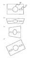
図4は発光ターゲット装置の発光部が複数ある例である。例えば、ボクシングのグローブに見立てた発光ターゲット装置に発光部15,16をおのおの埋め込み、タイミング信号に同期して発光させる。このグローブに見立てた発光ターゲット装置を人物17が操作する。ここで、図1の画像獲得装置のように反射光画像のみを用いると、手だけでなく体全体も映るため、その中から手の部分を切り出す必要が生じる。しかしこのようにアクティブにターゲットを発光させることで、グローブの位置だけを正確に取得することができる。
【0029】
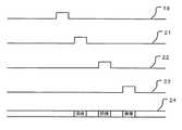
また、2つのグローブを明確に分離して取得したければ、ひとつのタイミング信号に対し、各々異なるタイミングで発光し、2回撮像することで実現可能である。その場合のタイミング信号の例を図5に示す(この例は、発光部が3つの場合)。受信したタイミング信号18に対し、3つの発光手段を駆動するためのタイミング信号21、22、23を順次発生させており、それにあわせて3回の撮像を行っている(24)。
【0030】
また、図6のようにタイミング発生側より、タイミングと同時に、コード情報を送り、そのコードにあわせて異なる発光手段を発光させるようにすることもできる。25、28がタイミングと共にコード情報を送っている波形パタンであり、26、29はそれぞれ異なる発光手段に対応する駆動信号である。これにより、モードにより異なる特徴量を取得したい場合などに適用することができる。
【0031】
<スイッチを持った発光ターゲット装置> 発光ターゲット装置にスイッチを付け加え、そのスイッチの状態によって、発光ターゲット装置の状態が変わるように構成するとより応用範囲が広がる。
【0032】
図7はこのスイッチを持った発光ターゲットの構成図を示す。図2のブロック図との構成の違い箇所のみ説明する。図7の発光ターゲット装置の構成は、図2の構成の発光ターゲット装置31にスイッチ部32を付加したものである。これは例えばボタンやスライドレバーなど様々な形態が考えられる。受光部7で受光されたタイミング信号でタイミング制御部8が発光部10を発光させるが、その際にスイッチ手段からの入力によって、異なる状態で発光させる。
【0033】
構成の仕方は様々あるが、回路をなるべくシンプルなままに維持するには、拡散反射する部分の一部や全部を、スイッチ動作で一時的に覆るような機構にしておき、発光の形状の変化を捉えるようにするのが良い。
【0034】
このような構成の発光ターゲット装置をビデオゲーム用の入力装置として考えると、主にプレイヤーによって操作されて使用されることになる。そして、その入力装置にスイッチが付いており、そのスイッチを押すことによって様々な状態を表せれば、より楽しめるようになる。
【0035】
例えば、拳銃の形をした遊具にこの装置を取り付けるものとする。拳銃を近くに画像獲得装置が設置されているような画面に向けると、拳銃の方向が検出することができる。引き金はスイッチになっており、引き金を引くことで発光ターゲット装置の状態が変わる。例えば、通常は発光していない発光部10が追加で発光したり、発光量が一時的に増減したり、拡散反射させる形状が変化する。そして、画像獲得装置の処理よってこの変化は検出され、拳銃の引き金が引かれたことが検出される。
【0036】
また、ゲームの中で使われるアイテム(道具)としての遊具を作った場合、そこにスイッチがあり、それを押すごとに様々なモードに変わるようになれば、そのアイテムの使用方法に広がりが出てくる。
【0037】
<発光ターゲットがタイミングを主導する形態> 以上の例では、いずれも画像獲得装置側より、発光のタイミングを指定した。次の例では、発光ターゲットが自発的に発光し、画像獲得装置側は、その発光タイミングを検出すると同時に、画像を取得する形態を示す。この場合、発光ターゲット側は、受光部という構成を持たなくて良いため、より単純な回路構成となり、発光ターゲットをより低コストで構成できるメリットがある。
【0038】
この実施例の構成を図8に示す。発光ターゲット35はよりシンプルな構成となり、発光制御部33が発光部34をパルス上に発光させるのみである。光拡散板9はこれまでのものと同様である。画像獲得装置38では、受光部36で光拡散板9を経由した光を受光するが、これは発光のタイミングを検出するために用いられる。受光部36の出力はタイミング検出部37でタイミング信号に変換され、制御部3に送られる。制御部3はこのタイミング信号に従ってイメージセンサ1に撮像させる。撮像のタイミングは、図3(a)のように、発光ターゲットが発光していると判断される時に撮像動作を行う。実際には、それと近接して、非発光時に第2の撮像を行い、差分出力として、発光ターゲットのみの画像を得ることになる。
【0039】
<拡散面の形状> ここで、これまで述べてきた発光ターゲット装置の拡散板9の拡散面の形状について述べる。特に、発光ターゲットの光源の位置取得するのに適している拡散板9の拡散面の形状の幾何学的特徴量について述べる。
【0040】
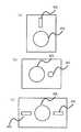
本願発明のような目的で使われる拡散面形状のうち、もっともシンプルなものは、図9(a)のように周りを黒色で囲まれた、円状の拡散形状である。ここで、検出された画像にこの拡散面からの光のみが映っていれば、その重心などを計算することで、発光ターゲットの光源の位置を容易に求めることが出来る。黒色で周りを囲むのは、仮に周囲に画像に移りこむような光源があったとしても、拡散面の回りは必ず何も映らない領域があるため、そのような外部光源から分離させることが容易になるからである。
【0041】
また、図9(b)のように、黒色の領域は必ずしも円形でなくても四角でも良い。必ずしも黒色である必要はないし、影響を与える外部光源が無い場合には、無くても構わない。単純に位置だけを求めたい場合にはこのような形状が適している。また、ターゲットまでの距離によって、その画像内での大きさが変わるため、面積を計算すれば、距離を求めることが出来る。
【0042】
しかし、拡散面が円である場合は、その面が画像獲得装置の方向からずれると、図9(c)のように形状が楕円に変化する。この場合でも最も長い系を求めれば、距離に換算できるが、面積を用いた場合は、若干小さくなってしまう。そこで、拡散面が球状であれば、図9(d)のように発光ターゲットの向きによらず常に円に見えるため、面積を距離に変換することが可能になる。しかし、一般的には全く球状に拡散面を構成するのはそれほど容易ではない。
【0043】
また、他の形状として、図10(a)のような形状が考えられる。この場合、複数の光源40〜43が画像として映り、それらの中心距離をターゲットまでの距離に換算することが出来る。この場合は、発光部を複数持つ場合もあるし、ひとつの発光部を、拡散板の形状で複数に分ける場合もある。この場合、 発光ターゲットの向きによって四角形がゆがむため、それらの計算より、面の向きを求めることができる。
【0044】
また、図10(b)のような形状にすると、向きをより精度良く求めることができる。ここでは、発光部44が他の4つの発光部が位置する平面より前に飛び出している。画像撮像装置にまっすぐ向いている場合は、発光部44の位置と他の4つの発光部の位置の真ん中が同じになるが、ずれている場合は一致しない。このような形状の拡散板を拳銃のような遊具の先に取り付けると、照準が合っているかどうかを効率的に検出できる。
【0045】
また、発光ターゲットの向きを効率よく求めたい場合は、さらに異なる形状の拡散面を使用するとよい。例えば、図11(a),(b)のような拡散面を用いれば、ターゲットが画像獲得装置の方向に向いた状態での回転(傾き)を検出できる。この形状では、大きな発光面45の横に小さな発光面46がある。大きな発光面の中心に対して、小さな発光面がどの位置(上下左右)にあるかを見れば、回転方向の位置が分かる。
【0046】
図11(c)の場合は、左右反転した場合は見分けがつかないが、両側にある分、発光ターゲットの向きを検出する精度が上がる。つまり、図11(c)のような発光ターゲットを用いた場合、図12に示すような様々な向きを検出できる。
【0047】
図12(a)のように、まっすぐ向いている場合は、中央の大きな発光面は円であり、その中心を求めることで、ターゲット位置が分かる。また、図12(b),(c)のように傾いた場合は、その円のひずみかたで向きが分かる。例えば、中央の大きな発光面45は楕円状に見えるが、その長径の方向を軸に傾いていることがわかり、傾きの度合いは、長径と短径の比で分かる。また、図12(d)のように回転している場合は、小さな発光面を結んだ直線の傾きで検出できる。
【0048】
また、図13のように棒状の遊具に、何ヶ所かの発光部47〜49を設けて、その棒の向きなどを検出することが出来る。これは剣を持って戦うようなゲームに適している。複数の発光部の中心を通る線から、剣の長手方向が分かり、その長手方向に垂直な方向の幅を見れば、その発光面の距離が分かる。
【0049】
拡散形状はこれ以外にも様々考えられるが、特定の幾何学的特徴量を効率的に検出するために形作られた拡散形状はすべて本特許の範囲内にある。
【0050】
<反射率の異なる物体で構成された反射ターゲット> これまでの実施例はいずれも、発光ターゲットが光を発光して、画像獲得装置によってその幾何学的情報が捉えやすくするものであった。次に、発光部は使わずに、かつ画像獲得装置による動作検出を補助する装置を説明する。この装置は、反射光画像獲得装置の発光部が発光する光を、よく反射する物体と、逆に反射しない(吸収する)物体を、取得したい幾何学的情報を適切に取り出せるように工夫された形状、配置で構成されたものである。
【0051】
図14は発光部を用いない反射ターゲットを用いた入力装置の構成である。この場合、図1に記載の、基本となる反射光画像獲得装置と共に用いられる。つまり、画像獲得装置の発光部12からの光を反射ターゲット50にて反射する。反射ターゲット50は上述したように、反射する物体と、逆に反射しない(吸収する)物体を、取得したい幾何学的情報を適切に取り出せるように工夫された形状、配置で構成する。そして、反射率の高い形状の部分による反射光を光学系4を介してイメージセンサ1にて受光する。イメージセンサ1の撮像のタイミングや発光部12の発光のタイミングは、図1や図2の構成と同様に制御部11にて制御する。
【0052】
なお、反射率の高い部分の形状は、発光ターゲットと同様に、特定の特徴量を求めるのに適した形状をしていることが特徴となる。
【0053】
また、発光ターゲットと同様に、スイッチ手段を持って、そのスイッチの状態によって反射ターゲットの形状が変わるようにするのも効果的である。
【0054】
このような構成により、発光部を用いるよりは、検出は楽では無いが、反射率の高いものを用いれば、体などに装着しても、体自体よりも十分明るい反射光を得ることが出来るので、検出は比較的容易になる。またこの場合は、反射率の高い物体の周りを反射率の低い物体で囲むのが重要になる。そうすることで、比較的反射率の高いものが近くに存在しても、十分弁別できる。この場合、逆に反射率の低い物体の周りを高い物体で囲んでも同様の効果がある。
【0055】
以上のような、本願発明の実施形態によれば次のような作用効果が得られる。つまり、従来でも発光手段によって対象物体を照射し、その物体反射光のみを画像として撮像する手段を用いると、近くの対象物体を背景から分離して検出することができ、その動きなどの情報を容易に取り出せることが出来た。
【0056】
しかし、遠くの対象物体を取得しようとすると、次第に背景との輝度差が少なくなり、検出が容易でなくなってくる。また体全体を捉えた場合、そこから手だけの位置を検出するような場合は、ある程度の画像解析が必要であった。本発明はそのような状況に用いることができ、遠い距離にあってもその装置を装着または保持して動作することで、その動きを確実に検出できる。
【0057】
一方、ビデオゲームのようなアプリケーションにこれらを適用する場合の効果を考えてみる。からだの動作を使ってゲームを楽しむことが出来るのは非常にその楽しみを増大させるものである。しかし場合によっては、何か「もの」を持って動作をするほうがよりリアルである場合がある。例えば、射撃をするゲームであれば、手で拳銃の形を作るのも良いが、やはり拳銃の形をした遊具を持って、遊ぶのがよりリアルであり楽しい。また剣術を使うゲームであれば、剣に相当する棒状の遊具を持って振り回すほうがより楽しい。
【0058】
その場合にその遊具を効率的に検出できる装置があれば、非常に効果的である。遊具を色でマーキングしておき、ビデオカメラで撮影して色情報を元に検出するという方法もあるが、複雑な背景から同じ色を拾ってしまったり、まわりの照明条件で色が変わって見えたりするなど、十分な精度で検出することは非常に難しい。本発明に依れば、検出は非常に容易となる。
【0059】
現在でも、ゲームをするための様々な遊具はある。例えば加速度センサを内蔵していて、その動きを検出するようなものもある。しかし、正確な位置を求めるのは比較的難しく、またそれ専用の装置を作るにはそれなりのコストがかかる。本発明では、画像獲得装置は比較的複雑なシステムであるが、発光ターゲットや反射ターゲットは非常に簡単な装置であり非常に廉価に製造できる。画像獲得装置さえはじめに購入すれば、あとは比較的安価な遊具を購入するだけでさまざまな遊び方が出来るようになる。
【0060】
【発明の効果】
以上、説明したように本願発明よれば、取得対象となる物体が遠い距離にあっても対象物体にターゲット装置を装着または保持して動作することで、対象物体の動きを確実に検出できるという優れた効果を奏し得る。
【図面の簡単な説明】
【図1】本願発明の一実施例の基本となる反射光撮像装置
【図2】本願発明の一実施例である発光ターゲット装置と画像獲得装置
【図3】本願発明の一実施例である発光ターゲットと画像獲得装置の動作タイミングを示す図
【図4】本願発明の一実施例である複数の発光ターゲットを用いた例
【図5】本願発明の一実施例である発光ターゲットと画像獲得装置の動作タイミングを示す図
【図6】本願発明の一実施例である発光ターゲットと画像獲得装置の動作タイミングを示す図
【図7】本願発明の一実施例であるスイッチ部を持つ発光ターゲットの例
【図8】本願発明の一実施例であるタイミング信号を受信しない発光ターゲットの例
【図9】本願発明の一実施例である発光ターゲットの拡散面の形状の例
【図10】本願発明の一実施例である発光ターゲットの拡散面の形状の例
【図11】本願発明の一実施例である発光ターゲットの拡散面の形状の例
【図12】本願発明の一実施例である発光ターゲットの拡散面の形状の例
【図13】本願発明の一実施例である発光ターゲットの拡散面の形状の例
【図14】本願発明の一実施例である反射ターゲットの例
【符号の説明】
1 イメージセンサ
2 発光部
3 制御部
4 光学系
5 画像獲得装置
6 発光ターゲット装置
7 受光部
8 タイミング制御部
9 光拡散板
10 発光部[0001]
BACKGROUND OF THE INVENTION
The present invention is a technique for acquiring a person's movement and the like in a non-contact manner, and in particular, an input device that is held and worn by a target person and makes a light-emitting target used for the input device in order to make the detection more stable. The present invention relates to an image acquisition device used for a device and an input device.
[0002]
[Prior art]
Techniques for acquiring a person's movement without contact with the person have been used for a long time, and in particular, a technique for acquiring the movement of a person shown in the image sensor (camera) by analyzing the input. Has long been researched and developed. However, it is difficult to extract operation information stably because of the large amount of information and complexity of images.
[0003]
In response to this situation, Japanese Patent Application Laid-Open No. 10-177449 discloses a method for obtaining an image of only a target object by actively emitting light and capturing the reflected light of the object with an image sensor to remove the background. Has been. This utilizes the fact that the intensity of reflected light from a distant background is very small compared to the reflected light from a nearby target object, so that it hardly appears in the image.
[0004]
According to Japanese Patent Laid-Open No. 9-243325, it is shown that the position of the light source can be specified and the movement of the body can be acquired by wearing a light emitter and acquiring it with a CCD camera. ing. However, since the operation is acquired with a normal camera here, a bright part such as a window appears in the background, which may hinder detection. In addition, although it is mentioned that the distance is obtained depending on the size of the reflected light source, there is no mention about acquisition of other geometric features.
[0005]
[Problems to be solved by the invention]
In the case of using the apparatus disclosed in Japanese Patent Laid-Open No. 10-177449, a problem occurs when attempting to extend the distance range of the target object. That is, as the distance of the target object increases, the ratio of the distance between the target object and the background gradually decreases. The intensity of the reflected light from the object actually depends not only on the distance but also on the reflectance of the object surface and so on, and depending on those conditions, it may be difficult to separate the background from the target object.
[0006]
Basically, since the intensity of the reflected light is inversely proportional to the square of the object distance, for example, the intensity of 30 cm and that of 60 cm are four times different, so that the separation is easy. However, in the case of 1 m and 1
[0007]
The present invention proposes an auxiliary light emitting target device that is worn or held by a target object (in this case, a person in many cases) so that the operation can be easily detected even in such a situation. is there. In addition, an image acquisition device for interlocking with these auxiliary devices is also described, and an input device combining them is proposed.
[0008]
[Means for Solving the Problems]
The present invention is a timing signal transmitting means for transmitting a timing signal by light or radio,SaidTiming signal receiving means for receiving the timing signal transmitted by the timing signal transmitting means;SaidLight emitting means for emitting light at a timing corresponding to the timing signal received by the timing signal receiving means;SaidA light diffusing means for diffusing and emitting light emitted by the light emitting means in a specific shape;SaidImaging means for imaging light from the light emitting means diffused through the light diffusing means;Geometric feature detection means for detecting a geometric feature from the shape of light imaged by the imaging meansIt is characterized by doing.
[0009]
A timing signal transmitting means for transmitting the timing signal by light or wireless;SaidTiming signal receiving means for receiving the timing signal transmitted by the timing signal transmitting means;SaidLight emitting means for emitting light at a timing corresponding to the timing signal received by the timing signal receiving means;SaidA light diffusing means for diffusing and emitting light emitted by the light emitting means in a specific shape;SaidAn imaging means for imaging only the light emitted at a specific time associated with the light emission timing of the light emitting means;Geometric feature detection means for detecting a geometric feature from the shape of light imaged by the imaging meansIt is characterized by doing.
[0010]
A light emitting means for emitting light in pulses;SaidA light diffusing means for diffusing and emitting light emitted by the light emitting means in a specific shape;SaidTiming detection means for detecting the timing of light emission from the light emitting means;SaidThe light emission timing or the light emission timing is synchronized with the light emission timing detected by the timing detection means.timingImaging means for imaging only light emitted at a specific time associated with;Geometric feature detection means for detecting a geometric feature from the shape of light imaged by the imaging meansIt is characterized by doing.
[0011]
Also,Light emitting means for emitting light, light reflecting means for reflecting light emitted by the light emitting means in a specific shape, imaging means for imaging light reflected from the light reflecting means, and images taken by the imaging means Geometric feature detecting means for detecting a geometric feature from the shape of light is provided.
[0012]
Also,A light emitting means that emits light at a certain timing, a light reflecting means that reflects light emitted by the light emitting means in a specific shape, and only light emitted at a specific time associated with the light emission timing of the light emitting means. An image pickup means for picking up an image and a geometric feature detection means for detecting a geometric feature from the shape of light picked up by the image pickup means are provided.
[0013]
Also,Light emitting means for emitting light in pulses, light reflecting means for reflecting light emitted by the light emitting means in a specific shape, timing detection means for detecting the timing of light emission from the light emitting means, and the timing An imaging unit that captures only light emitted at a specific time associated with the light emission timing or the light emission timing in synchronization with the light emission timing detected by the detection unit, and the shape of the light imaged by the imaging unit It comprises a geometric feature detecting means for detecting a geometric feature from.
[0014]
With such a configuration, even when the object to be acquired is at a long distance, the movement of the target object can be reliably detected by operating with the target device mounted or held on the target object.
[0015]
DETAILED DESCRIPTION OF THE INVENTION
Hereinafter, embodiments of the present invention will be described with reference to the drawings.
[0016]
<Basic System> FIG. 1 shows a basic configuration of a reflected light image acquisition apparatus targeted by the present invention. The details of the reflected light image acquisition device are described in detail in Japanese Patent Application Laid-Open No. 10-177449, and therefore only an outline is given here. The
[0017]
Unlike a normal image, the
[0018]
<Light-Emitting Target Device> FIG. 2 describes a first embodiment of the present invention. The
[0019]
The
[0020]
The
[0021]
A conventional reflected light image acquisition device can also be used as it is. This is because the light emitting unit of the original image acquisition device has a wide light emission directivity characteristic, so that it can receive light if it is a light receiving unit present in the imaging target range. Since the light emitting target for receiving light does not always face the image acquisition device, it is important that light is diffused by a diffusion plate or the like.
[0022]
Here, several variations are conceivable for the timing signal generation timing and the imaging timing of the image sensor in the
[0023]
In FIG. 3, the timing generation pulse and the light emission pulse of the light emission target have the same width. However, the timing is merely given, and if the light emission width is fixed, the pulse width does not necessarily have to be the same. The same applies to the following other variations.
[0024]
When operated at the timing shown in FIG. 3A, the same
[0025]
In such a case, the
[0026]
In addition, if the configuration is changed from the basic system and radio waves or ultrasonic waves are used, there is no fear of interference, and the wavelength of the timing
[0027]
The number of light emitting
[0028]
FIG. 4 shows an example in which there are a plurality of light emitting units of the light emitting target device. For example, each of the
[0029]
Further, if it is desired to obtain two globes separately, this can be realized by emitting light at different timings for one timing signal and capturing images twice. FIG. 5 shows an example of the timing signal in that case (in this example, there are three light emitting units). Timing signals 21, 22, and 23 for driving the three light emitting means are sequentially generated with respect to the received
[0030]
Also, as shown in FIG. 6, code information can be sent from the timing generation side simultaneously with the timing, and different light emitting means can be made to emit light according to the code.
[0031]
<Light-emitting target device having a switch> The application range is further expanded by adding a switch to the light-emitting target device and changing the state of the light-emitting target device depending on the state of the switch.
[0032]
FIG. 7 shows a configuration diagram of a light emitting target having this switch. Only differences in configuration from the block diagram of FIG. 2 will be described. The configuration of the light emitting target device of FIG. 7 is obtained by adding a switch unit 32 to the light emitting
[0033]
There are various ways of configuration, but in order to keep the circuit as simple as possible, change the shape of the light emission by using a mechanism that temporarily covers part or all of the diffusely reflected part with a switch operation. It is better to catch.
[0034]
If the light emitting target device having such a configuration is considered as an input device for a video game, it is mainly used by being operated by a player. And if the input device has a switch, and it can express various states by pushing the switch, it will become more enjoyable.
[0035]
For example, assume that the device is attached to a play equipment in the shape of a handgun. The direction of the handgun can be detected by pointing the handgun toward a screen where an image acquisition device is installed nearby. The trigger is a switch, and the state of the light emitting target device is changed by pulling the trigger. For example, the
[0036]
Also, if you make a play equipment as an item (tool) used in the game, if there is a switch there and it changes to various modes each time you press it, the usage of that item will spread. Come.
[0037]
<Embodiment in which the light emitting target leads the timing> In the above examples, the timing of light emission is designated from the image acquisition device side. In the following example, the light emission target emits light spontaneously, and the image acquisition device side detects the light emission timing and simultaneously acquires an image. In this case, since the light emitting target side does not need to have a configuration of a light receiving unit, the circuit configuration is simpler, and there is an advantage that the light emitting target can be configured at a lower cost.
[0038]
The configuration of this embodiment is shown in FIG. The
[0039]
<Shape of Diffusion Surface> Here, the shape of the diffusion surface of the diffusion plate 9 of the light emitting target device described so far will be described. In particular, the geometric feature amount of the shape of the diffusion surface of the diffusion plate 9 suitable for acquiring the position of the light source of the light emitting target will be described.
[0040]
Of the diffusing surface shapes used for the purpose as in the present invention, the simplest one is a circular diffusing shape surrounded by black as shown in FIG. Here, if only the light from the diffusion surface is reflected in the detected image, the position of the light source of the light emitting target can be easily obtained by calculating the center of gravity. The surrounding area in black is easy to separate from such an external light source because there is always an area around the diffusion surface even if there is a light source that moves into the surrounding image. Because it becomes.
[0041]
Further, as shown in FIG. 9B, the black region is not necessarily circular but may be square. It does not necessarily need to be black, and if there is no external light source that affects it, it may be omitted. Such a shape is suitable when only the position is desired. Further, since the size in the image changes depending on the distance to the target, the distance can be obtained by calculating the area.
[0042]
However, when the diffusing surface is a circle, when the surface deviates from the direction of the image acquisition device, the shape changes to an ellipse as shown in FIG. Even in this case, if the longest system is obtained, it can be converted into a distance, but if the area is used, it becomes slightly smaller. Therefore, if the diffusing surface is spherical, the area can be converted into a distance because it always looks circular as shown in FIG. 9D regardless of the direction of the light emitting target. However, in general, it is not so easy to form a diffusing surface in a completely spherical shape.
[0043]
As another shape, a shape as shown in FIG. In this case, the plurality of
[0044]
Further, when the shape is as shown in FIG. 10B, the orientation can be obtained with higher accuracy. Here, the
[0045]
In addition, when it is desired to efficiently obtain the direction of the light emitting target, it is preferable to use a diffusion surface having a different shape. For example, if a diffusing surface as shown in FIGS. 11A and 11B is used, it is possible to detect rotation (inclination) in a state where the target faces the image acquisition device. In this shape, there is a small
[0046]
In the case of FIG. 11 (c), it is difficult to distinguish when the left and right are reversed, but the accuracy of detecting the direction of the light emitting target is increased by the amount on both sides. That is, when the light emitting target as shown in FIG. 11C is used, various directions as shown in FIG. 12 can be detected.
[0047]
As shown in FIG. 12A, when the light is directed straight, the large light emitting surface at the center is a circle, and the target position can be found by obtaining the center. Also, when tilted as shown in FIGS. 12B and 12C, the direction can be determined by the distortion of the circle. For example, the large light-emitting
[0048]
Further, as shown in FIG. 13, a bar-shaped playground equipment is provided with several
[0049]
Various other diffusion shapes are possible, but all diffusion shapes that are shaped to efficiently detect a particular geometric feature are within the scope of this patent.
[0050]
<Reflection Target Consists of Objects with Different Reflectances> In all of the examples so far, the light emitting target emits light, and the geometric information can be easily captured by the image acquisition device. Next, an apparatus for assisting motion detection by the image acquisition apparatus without using the light emitting unit will be described. This device was devised so that the geometrical information to be acquired can be appropriately extracted from objects that reflect well and objects that do not reflect (absorb) the light emitted by the light emitting unit of the reflected light image acquisition device. It consists of shape and arrangement.
[0051]
FIG. 14 shows a configuration of an input device using a reflective target that does not use a light emitting unit. In this case, it is used together with the basic reflected light image acquisition device shown in FIG. That is, the light from the
[0052]
Note that the shape of the portion having a high reflectance is characterized by a shape suitable for obtaining a specific feature amount, like the light emitting target.
[0053]
Further, similarly to the light emitting target, it is also effective to have switch means so that the shape of the reflective target changes depending on the state of the switch.
[0054]
With such a configuration, detection is not easier than using a light emitting unit, but if a highly reflective material is used, reflected light that is sufficiently brighter than the body itself can be obtained even when worn on the body. Therefore, detection becomes relatively easy. In this case, it is important to surround an object having a high reflectance with an object having a low reflectance. By doing so, even if a relatively high reflectance exists nearby, it can be sufficiently discriminated. In this case, on the contrary, the same effect can be obtained by surrounding an object having a low reflectance with a high object.
[0055]
According to the embodiment of the present invention as described above, the following operational effects can be obtained. In other words, using a means for illuminating a target object with a light emitting means and capturing only the reflected light of the object as an image, a nearby target object can be detected separately from the background. I was able to take it out easily.
[0056]
However, when trying to acquire a distant target object, the brightness difference from the background gradually decreases, making detection difficult. In addition, when the whole body is captured, a certain amount of image analysis is required when detecting the position of the hand alone. The present invention can be used in such a situation, and the movement can be reliably detected by operating with the apparatus mounted or held even at a long distance.
[0057]
On the other hand, consider the effect of applying these to applications such as video games. Being able to enjoy the game using body movements greatly increases that enjoyment. However, in some cases, it is more realistic to operate with something. For example, if it is a shooting game, you can make a handgun shape with your hands, but it is still more realistic and fun to play with a playground equipment shaped like a handgun. Also, if it is a game that uses swordsmanship, it is more fun to swing around with a stick-shaped playground equipment equivalent to a sword.
[0058]
In this case, if there is a device that can efficiently detect the playground equipment, it is very effective. There is a method of marking the playground equipment with color and then shooting with a video camera and detecting it based on the color information, but the same color is picked up from a complicated background, or the color changes depending on the surrounding lighting conditions It is very difficult to detect with sufficient accuracy. According to the present invention, detection is very easy.
[0059]
There are still various playground equipment for playing games. For example, there is a built-in acceleration sensor that detects its movement. However, it is relatively difficult to obtain an accurate position, and it is expensive to make a dedicated device. In the present invention, the image acquisition device is a relatively complicated system, but the light emitting target and the reflection target are very simple devices and can be manufactured at a very low cost. If you purchase an image acquisition device at the beginning, you will be able to play various ways just by purchasing relatively inexpensive playground equipment.
[0060]
【The invention's effect】
As described above, according to the present invention, it is possible to reliably detect the movement of the target object by operating with the target device mounted or held on the target object even when the object to be acquired is at a long distance. The effects can be achieved.
[Brief description of the drawings]
FIG. 1 is a reflected light imaging apparatus serving as a basis of an embodiment of the present invention;
FIG. 2 shows a light emitting target device and an image acquisition device according to an embodiment of the present invention.
FIG. 3 is a diagram showing the operation timing of a light emitting target and an image acquisition device according to an embodiment of the present invention.
FIG. 4 shows an example using a plurality of light emitting targets according to an embodiment of the present invention.
FIG. 5 is a diagram showing the operation timing of a light emitting target and an image acquisition device according to an embodiment of the present invention.
FIG. 6 is a diagram showing the operation timing of a light emitting target and an image acquisition device according to an embodiment of the present invention.
FIG. 7 shows an example of a light emitting target having a switch unit according to an embodiment of the present invention.
FIG. 8 shows an example of a light emitting target that does not receive a timing signal according to an embodiment of the present invention.
FIG. 9 shows an example of the shape of the diffusion surface of the light emitting target according to one embodiment of the present invention.
FIG. 10 shows an example of the shape of the diffusion surface of a light emitting target according to an embodiment of the present invention.
FIG. 11 shows an example of the shape of the diffusion surface of a light emitting target according to an embodiment of the present invention.
FIG. 12 shows an example of the shape of the diffusion surface of a light emitting target according to an embodiment of the present invention.
FIG. 13 shows an example of the shape of the diffusion surface of a light emitting target according to an embodiment of the present invention.
FIG. 14 shows an example of a reflective target according to an embodiment of the present invention.
[Explanation of symbols]
1 Image sensor
2 Light emitting part
3 Control unit
4 Optical system
5 Image acquisition device
6 Light emitting target device
7 Light receiver
8 Timing controller
9 Light diffuser
10 Light emitting part
Claims (13)
Translated fromJapanese前記タイミング信号発信手段にて発信された前記タイミング信号を受信するタイミング信号受信手段と、
前記タイミング信号受信手段にて受信したタイミング信号に対応するタイミングで発光する発光手段と、
前記発光手段によって発光される光を、特定形状で拡散発光させる光拡散手段と、
前記光拡散手段を介して拡散された前記発光手段による光を撮像する撮像手段と、
前記撮像手段により撮像された光の形状から幾何学的特徴を検出する幾何学的特徴検出手段を具備することを特徴とする入力装置。Timing signal transmitting means for transmitting the timing signal by light or wireless;
A timing signal receiving means for receiving the timing signal transmitted bythe timing signal transmitting means,
Light emitting means for emitting light at a timing corresponding to the timing signal received bysaid timing signal receiving means,
The light emitted bysaid light emitting means, a light diffusing means for diffusing the light emitting in a specific shape,
Imaging means for imaging the light from said light emitting means which is diffused throughthe light diffusing means,
An input devicecomprising geometric feature detection means for detecting a geometric feature from the shape of light imaged by the imaging means .
前記タイミング信号発信手段にて発信された前記タイミング信号を受信するタイミング信号受信手段と、
前記タイミング信号受信手段にて受信したタイミング信号に対応するタイミングで発光する発光手段と、
前記発光手段によって発光される光を、特定形状で拡散発光させる光拡散手段と、
前記発光手段の発光するタイミングに関連付けられた特定の時間に発せられた光のみを撮像する撮像手段と、
前記撮像手段により撮像された光の形状から幾何学的特徴を検出する幾何学的特徴検出手段を具備することを特徴とする入力装置。Timing signal transmitting means for transmitting the timing signal by light or wireless;
A timing signal receiving means for receiving the timing signal transmitted bythe timing signal transmitting means,
Light emitting means for emitting light at a timing corresponding to the timing signal received bysaid timing signal receiving means,
The light emitted bysaid light emitting means, a light diffusing means for diffusing the light emitting in a specific shape,
Imaging means for imaging only light emitted to the particular time associated with the light emitting timing ofthe light emitting means,
An input devicecomprising geometric feature detection means for detecting a geometric feature from the shape of light imaged by the imaging means .
前記発光手段によって発光される光を、特定形状で拡散発光させる光拡散手段と、
前記発光手段からの発光のタイミングを検出するためのタイミング検出手段と、
前記タイミング検出手段によって検出された発光のタイミングに同期し、前記発光のタイミングあるいは発光のタイミングと関連付けられた特定の時間に発光した光のみを撮像する撮像手段と、
前記撮像手段により撮像された光の形状から幾何学的特徴を検出する幾何学的特徴検出手段を具備することを特徴とする入力装置。A light emitting means for emitting light in pulses;
The light emitted bysaid light emitting means, a light diffusing means for diffusing the light emitting in a specific shape,
A timing detection means for detecting the timing of light emission fromthe light emitting means,
Imaging means for imagingthe synchronization with the timing of the light emission detected by the timing detecting means, only the light emission at a particular time associated with the timing or the light emittingtiming of the light emission,
An input devicecomprising geometric feature detection means for detecting a geometric feature from the shape of light imaged by the imaging means .
前記発光手段によって発光される光を、特定形状で反射させる光反射手段と、A light reflecting means for reflecting the light emitted by the light emitting means in a specific shape;
前記光反射手段から反射された光を撮像する撮像手段と、Imaging means for imaging light reflected from the light reflecting means;
前記撮像手段により撮像された光の形状から幾何学的特徴を検出する幾何学的特徴検出手段を具備することを特徴とする入力装置。An input device comprising geometric feature detection means for detecting a geometric feature from the shape of light imaged by the imaging means.
前記発光手段によって発光される光を、特定形状で反射させる光反射手段と、
前記発光手段の発光するタイミングに関連付けられた特定の時間に発せられた光のみを撮像する撮像手段と、
前記撮像手段により撮像された光の形状から幾何学的特徴を検出する幾何学的特徴検出手段を具備することを特徴とする入力装置。A light emitting means for emitting light at a certain timing;
A light reflecting means for reflecting the light emitted by the light emitting means in a specific shape;
Imaging means for imaging only the light emitted at a specific time associated with the light emission timing of the light emitting means;
An input devicecomprising geometric feature detection means for detecting a geometric feature from the shape of light imaged by the imaging means .
前記発光手段によって発光される光を、特定形状で反射させる光反射手段と、
前記発光手段からの発光のタイミングを検出するためのタイミング検出手段と、
前記タイミング検出手段によって検出された発光のタイミングに同期し、前記発光のタイミングあるいは発光のタイミングと関連付けられた特定の時間に発光した光のみを撮像する撮像手段と、
前記撮像手段により撮像された光の形状から幾何学的特徴を検出する幾何学的特徴検出手段を具備することを特徴とする入力装置。A light emitting means for emitting light in pulses;
A light reflecting means for reflecting the light emitted by the light emitting means in a specific shape;
Timing detection means for detecting the timing of light emission from the light emitting means;
Imaging means for imaging only the light emitted at a specific time associated with the light emission timing or the light emission timing in synchronization with the light emission timing detected by the timing detection means;
An input devicecomprising geometric feature detection means for detecting a geometric feature from the shape of light imaged by the imaging means .
Priority Applications (1)
| Application Number | Priority Date | Filing Date | Title |
|---|---|---|---|
| JP2001277435AJP3748526B2 (en) | 2001-09-13 | 2001-09-13 | Input device |
Applications Claiming Priority (1)
| Application Number | Priority Date | Filing Date | Title |
|---|---|---|---|
| JP2001277435AJP3748526B2 (en) | 2001-09-13 | 2001-09-13 | Input device |
Publications (2)
| Publication Number | Publication Date |
|---|---|
| JP2003083716A JP2003083716A (en) | 2003-03-19 |
| JP3748526B2true JP3748526B2 (en) | 2006-02-22 |
Family
ID=19101960
Family Applications (1)
| Application Number | Title | Priority Date | Filing Date |
|---|---|---|---|
| JP2001277435AExpired - Fee RelatedJP3748526B2 (en) | 2001-09-13 | 2001-09-13 | Input device |
Country Status (1)
| Country | Link |
|---|---|
| JP (1) | JP3748526B2 (en) |
Families Citing this family (2)
| Publication number | Priority date | Publication date | Assignee | Title |
|---|---|---|---|---|
| CN101185054B (en)* | 2005-05-31 | 2011-11-23 | 皇家飞利浦电子股份有限公司 | Method for control of a device |
| JP5431462B2 (en)* | 2008-05-26 | 2014-03-05 | マイクロソフト インターナショナル ホールディングス ビイ.ヴイ. | Control virtual reality |
- 2001
- 2001-09-13JPJP2001277435Apatent/JP3748526B2/ennot_activeExpired - Fee Related
Also Published As
| Publication number | Publication date |
|---|---|
| JP2003083716A (en) | 2003-03-19 |
Similar Documents
| Publication | Publication Date | Title |
|---|---|---|
| KR100993033B1 (en) | Entertainment system | |
| JP5089078B2 (en) | Game device | |
| US10445884B2 (en) | Control device for communicating visual information | |
| US8696459B2 (en) | Measurement and segment of participant's motion in game play | |
| US8651666B2 (en) | Interactive projector system and method | |
| EP1435258A2 (en) | An apparatus and a method for more realistic shooting video games on computers or similar devices using visible or invisible light | |
| CN103337111B (en) | For transmitting the opertaing device of visual information | |
| JP4906391B2 (en) | Game controller | |
| EP2590058B1 (en) | Game device, method of game control, and game control program | |
| JP2005253505A (en) | Moving object measuring apparatus | |
| US20030199325A1 (en) | Apparatus and a method for more realistic shooting video games on computers or similar devices using visible or invisible light and an input computing device | |
| JP3748526B2 (en) | Input device | |
| JP2001062149A (en) | Spot light position detection system and simulator | |
| JPH08215416A (en) | Toy system with inter-matching robot | |
| GB2470597A (en) | Detecting movement or shape of a reflective element in an image | |
| JP5551675B2 (en) | Game apparatus and virtual object control method | |
| US20250294132A1 (en) | Retro-reflective show element systems and methods | |
| WO2025199139A1 (en) | Retro-reflective show element systems and methods |
Legal Events
| Date | Code | Title | Description |
|---|---|---|---|
| RD02 | Notification of acceptance of power of attorney | Free format text:JAPANESE INTERMEDIATE CODE: A7422 Effective date:20050414 | |
| A977 | Report on retrieval | Free format text:JAPANESE INTERMEDIATE CODE: A971007 Effective date:20050510 | |
| RD04 | Notification of resignation of power of attorney | Free format text:JAPANESE INTERMEDIATE CODE: A7424 Effective date:20050606 | |
| A131 | Notification of reasons for refusal | Free format text:JAPANESE INTERMEDIATE CODE: A131 Effective date:20050621 | |
| A521 | Request for written amendment filed | Free format text:JAPANESE INTERMEDIATE CODE: A523 Effective date:20050822 | |
| TRDD | Decision of grant or rejection written | ||
| A01 | Written decision to grant a patent or to grant a registration (utility model) | Free format text:JAPANESE INTERMEDIATE CODE: A01 Effective date:20051125 | |
| A61 | First payment of annual fees (during grant procedure) | Free format text:JAPANESE INTERMEDIATE CODE: A61 Effective date:20051128 | |
| FPAY | Renewal fee payment (event date is renewal date of database) | Free format text:PAYMENT UNTIL: 20091209 Year of fee payment:4 | |
| FPAY | Renewal fee payment (event date is renewal date of database) | Free format text:PAYMENT UNTIL: 20091209 Year of fee payment:4 | |
| FPAY | Renewal fee payment (event date is renewal date of database) | Free format text:PAYMENT UNTIL: 20101209 Year of fee payment:5 | |
| FPAY | Renewal fee payment (event date is renewal date of database) | Free format text:PAYMENT UNTIL: 20111209 Year of fee payment:6 | |
| FPAY | Renewal fee payment (event date is renewal date of database) | Free format text:PAYMENT UNTIL: 20121209 Year of fee payment:7 | |
| FPAY | Renewal fee payment (event date is renewal date of database) | Free format text:PAYMENT UNTIL: 20121209 Year of fee payment:7 | |
| FPAY | Renewal fee payment (event date is renewal date of database) | Free format text:PAYMENT UNTIL: 20131209 Year of fee payment:8 | |
| LAPS | Cancellation because of no payment of annual fees |