JP3747740B2 - Detour control method in Internet gateway system - Google Patents
Detour control method in Internet gateway systemDownload PDFInfo
- Publication number
- JP3747740B2 JP3747740B2JP2000154396AJP2000154396AJP3747740B2JP 3747740 B2JP3747740 B2JP 3747740B2JP 2000154396 AJP2000154396 AJP 2000154396AJP 2000154396 AJP2000154396 AJP 2000154396AJP 3747740 B2JP3747740 B2JP 3747740B2
- Authority
- JP
- Japan
- Prior art keywords
- failure
- network
- signal processing
- main signal
- telephone network
- Prior art date
- Legal status (The legal status is an assumption and is not a legal conclusion. Google has not performed a legal analysis and makes no representation as to the accuracy of the status listed.)
- Expired - Fee Related
Links
Images


Classifications
- H—ELECTRICITY
- H04—ELECTRIC COMMUNICATION TECHNIQUE
- H04M—TELEPHONIC COMMUNICATION
- H04M3/00—Automatic or semi-automatic exchanges
- H04M3/08—Indicating faults in circuits or apparatus
- H04M3/12—Marking faulty circuits "busy"; Enabling equipment to disengage itself from faulty circuits ; Using redundant circuits; Response of a circuit, apparatus or system to an error
- H—ELECTRICITY
- H04—ELECTRIC COMMUNICATION TECHNIQUE
- H04L—TRANSMISSION OF DIGITAL INFORMATION, e.g. TELEGRAPHIC COMMUNICATION
- H04L41/00—Arrangements for maintenance, administration or management of data switching networks, e.g. of packet switching networks
- H04L41/06—Management of faults, events, alarms or notifications
- H04L41/0654—Management of faults, events, alarms or notifications using network fault recovery
- H04L41/0663—Performing the actions predefined by failover planning, e.g. switching to standby network elements
- H—ELECTRICITY
- H04—ELECTRIC COMMUNICATION TECHNIQUE
- H04L—TRANSMISSION OF DIGITAL INFORMATION, e.g. TELEGRAPHIC COMMUNICATION
- H04L41/00—Arrangements for maintenance, administration or management of data switching networks, e.g. of packet switching networks
- H04L41/28—Restricting access to network management systems or functions, e.g. using authorisation function to access network configuration
- H—ELECTRICITY
- H04—ELECTRIC COMMUNICATION TECHNIQUE
- H04L—TRANSMISSION OF DIGITAL INFORMATION, e.g. TELEGRAPHIC COMMUNICATION
- H04L45/00—Routing or path finding of packets in data switching networks
- H04L45/22—Alternate routing
- H—ELECTRICITY
- H04—ELECTRIC COMMUNICATION TECHNIQUE
- H04L—TRANSMISSION OF DIGITAL INFORMATION, e.g. TELEGRAPHIC COMMUNICATION
- H04L45/00—Routing or path finding of packets in data switching networks
- H04L45/28—Routing or path finding of packets in data switching networks using route fault recovery
- H—ELECTRICITY
- H04—ELECTRIC COMMUNICATION TECHNIQUE
- H04L—TRANSMISSION OF DIGITAL INFORMATION, e.g. TELEGRAPHIC COMMUNICATION
- H04L47/00—Traffic control in data switching networks
- H04L47/10—Flow control; Congestion control
- H—ELECTRICITY
- H04—ELECTRIC COMMUNICATION TECHNIQUE
- H04L—TRANSMISSION OF DIGITAL INFORMATION, e.g. TELEGRAPHIC COMMUNICATION
- H04L69/00—Network arrangements, protocols or services independent of the application payload and not provided for in the other groups of this subclass
- H04L69/40—Network arrangements, protocols or services independent of the application payload and not provided for in the other groups of this subclass for recovering from a failure of a protocol instance or entity, e.g. service redundancy protocols, protocol state redundancy or protocol service redirection
- H—ELECTRICITY
- H04—ELECTRIC COMMUNICATION TECHNIQUE
- H04M—TELEPHONIC COMMUNICATION
- H04M7/00—Arrangements for interconnection between switching centres
- H04M7/12—Arrangements for interconnection between switching centres for working between exchanges having different types of switching equipment, e.g. power-driven and step by step or decimal and non-decimal
- H04M7/1205—Arrangements for interconnection between switching centres for working between exchanges having different types of switching equipment, e.g. power-driven and step by step or decimal and non-decimal where the types of switching equipement comprises PSTN/ISDN equipment and switching equipment of networks other than PSTN/ISDN, e.g. Internet Protocol networks
- H04M7/125—Details of gateway equipment
- H—ELECTRICITY
- H04—ELECTRIC COMMUNICATION TECHNIQUE
- H04L—TRANSMISSION OF DIGITAL INFORMATION, e.g. TELEGRAPHIC COMMUNICATION
- H04L63/00—Network architectures or network communication protocols for network security
- H04L63/08—Network architectures or network communication protocols for network security for authentication of entities
Landscapes
- Engineering & Computer Science (AREA)
- Signal Processing (AREA)
- Computer Networks & Wireless Communication (AREA)
- Computer Security & Cryptography (AREA)
- Telephonic Communication Services (AREA)
- Data Exchanges In Wide-Area Networks (AREA)
- Communication Control (AREA)
Abstract
Description
Translated fromJapanese【0001】
【発明の属する技術分野】
本発明は電話網とIP網(インターネットプロトコル網)との接続方法、障害検出方法及び迂回制御方法に係わる。本発明は、特に、シグナリングゲートウェイ/メディアゲートウェイ制御装置、ゲートウェイ装置より構成されるインターネットゲートウェイシステムにおいて、ゲートウェイ装置のIP網インタフェースの障害を検出し、前段の電話網へ回線閉塞、迂回指示を行う電話網とIP網との接続方法に係わる。
【0002】
【従来の技術】
現在、電話網においてノード間の障害を検出する手段としては、ネットワーク間インタフェースにおける対向ノードとの間の共通線信号リンク状態の監視、通話回線のフレームビットの監視、およびユーザ・網インタフェースにおける網側と端末との間の回線状態の監視などが行われており、また、ネットワークを構成する各ノードに対して障害や輻輳の通知や迂回指示を行う手段として、ネットワーク間インタフェースのNo.7共通線信号のメッセージ転送部(MTP:Message Transfer Part)による共通線信号の障害通知、迂回指示、およびISDNユーザ部(ISUP:ISDN User Part)による通話回線の閉塞信号による閉塞指示、およびTTC(Telecommunication Technology Commitee:(社)電信電話技術委員会))標準リダイレクション手順やITU−T(International Telecommunication Union)勧告/TTC標準ピボット手順による迂回指示を行う手段が実現されている。
【0003】
また、ユーザ・網インタフェースについてはIP網とのゲートウェイ装置を含むユーザ側装置より電話網に対して障害通知、迂回指示を行う手段はなく、網側での回線状態監視、着信転送による迂回などが行われている。この他に迂回の実現が可能な手段としてIN(Intelligent Network Internetwork Interface)手順におけるサービス制御点(SCP:Service Control Point)での着信番号を変換する際に、ネットワークの状態により変換後の番号を切り替えることににより迂回と同等な制御を行う手段がある。
【0004】
一方、IP網においてノード間の障害を検出する手段としては対向ノード間でIETF(Internet Engineering Task Force)のRFC(Request for Comments)792で規定されるICMP(Internet Control Message Protocol)のping等のメッセージを送受信することにより対向ノードとの間の輻輳/障害を検出する方法や、RFC1157で規定されるSNMP(Simple Network Management Protocol)マネージャやゲートキーパ等の網管理装置にてネットワークを構成する各ノードの装置状態を収集する方法がある。また、障害や輻輳の通知や迂回指示を行う方法として、ルータ、またはSNMPマネージャやゲートキーパ等の網管理装置よりRFC2453で規定されるRIP(Routing Information Protocol)、RFC2328で規定されるOSPF(Open Shortest Path Fast)、RFC1771で規定されるBGP(border gateway protocol)等のダイナミックルーティングプロトコルを用いてネットワークを構成する各ノードにルーチング情報を配信することにより迂回指示する方法が行われている。
【0005】
【発明が解決しようとする課題】
一つまたは複数の着番号で複数の回線を共有している複数のゲートウェイ装置より構成されるゲートウェイシステムを介して電話網とIP網とが相互接続されるサービス形態においては、電話網、IP網それぞれのネットワーク内での障害の検出を行い迂回制御を行う方法については前記のように実現されているが、電話網においてIP網内での障害/輻輳を認識できないため、同一着番号であっても正常に着信できる回線群が存在するにも拘わらず、IP網で障害となっているルーティング経路を使用する回線群に対して、着信が行われ、呼損、通信品質のサービス低下を引き起こすこととなる。
【0006】
本発明の目的はゲートウェイシステムを介して電話網とIP網とが相互接続されるサービス形態において、ゲートウエイシステムによってゲートウエイシステム内の装置及びIP網の障害を検出し、電話網に対して迂回を指示することにより上記障害経路を使用する回線群が選択されることを回避し、電話網とIP網の相互接続サービスにおける接続品質を保証できるゲートウェイ及び迂回制御方法を提供することにある。
【0007】
【課題を解決するための手段】
本発明では、ゲートウェイシステムのIP網インタフェース障害または輻輳を検出する手段の一つとして、ゲートウェイシステムにおいてゲートウェイシステム内部の滞留パケット数や内部リソースの監視を行い、ゲートウェイシステム内及びIP網へのアクセス経路の障害状態を検出することにより電話網からIP網への接続に対する回線状態の検出を行う機能を有する。
【0008】
また、上記ゲートウェイ装置より認証・課金やIPアドレス情報の取得のためにIP網の各種サーバに対してIPパケットを送出した場合のサーバからの応答時間についてタイマ監視を行い、応答がタイムアウトする頻度や要求送出からの応答時間の遅延状況を測定することにより、ゲートウェイシステムからIP網への接続に対するネットワーク障害・輻輳の検出を行う機能を有する。
【0009】
また、上記ゲートウェイシステムはゲートキーパ装置や網管理装置からのIP網内の障害情報を受信または問合せを行なう事により、サーバ群、ルータ等のIP網を構成する各ノードへのパケット送出可/不可情報を取得し、電話網からIP網への接続に対する回線状態の検出を行う機能を有する。
【0010】
また、上記ゲートウェイシステムはルータ等IP網を構成する各ノードより特定ルートに対するルーチング不可通知を受信した情報を分析することによりゲートウェイシステムからIP網への接続に対するネットワーク障害を検出する機能を有する。
【0011】
さらに本発明では上記手順によりIP網に接続する際にネットワーク障害や輻輳を検出したゲートウェイシステムは、障害/輻輳を検出した事を契機に、電話網に対してIP網へインタワークするために障害の発生しているゲートウェイシステム内装置への接続を規制し、他の装置への迂回を指示する手段として、電話網との回線インタフェースが使用不能である事を通知し、電話網が当該回線群を使用せずIP網へのアクセスに支障の無い回線に迂回を促す機能を有する。
【0012】
さらに本発明では、電話網に対して回線が使用不能である事を通知したのち障害がなくなった事を検出し、回線の使用が可能になった事を通知する機能を有する。また呼毎に障害を検出した場合には障害頻度によって回線が使用不能である事を電話網に通知する機能を有し、タイマにより使用解除を通知する機能を有する。また呼毎に障害を検出した場合には障害頻度によって回線が使用不能である事を一部の回線に対して電話網に通知し、残った回線への着信時の障害頻度を監視する事により障害からの復旧を検出して電話網に対して使用解除を通知する機能を有する。
【0013】
また、前記ゲートウェイシステムと電話網は、収容する回線群のうちゲートウエイシステム内の装置毎にルーティングできる着番号を電話網が管理していており、ゲートウエイシステムから使用可能な回線へのその迂回可能な着番号を電話網に対して指示する事により電話網に迂回を積極的に行わせる機能を有する。または当該呼が迂回可能である事をゲートウエイシステムから電話網に対して指示する事により電話網内にて有するSCP等をもちいた迂回機能を利用して、使用可能な回線に対して呼毎に迂回させる機能を有する。
【0014】
【発明の実施の形態】
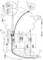
図1,図2は本発明におけるゲートウェイシステムを介した電話網とIP網(インターネットプロトコル)の網間相互接続の構成図の一例である。電話網(101)とIP網(102)は制御装置(110−a,b)および主信号処理装置(120−a,b)より構成されるゲートウェイシステム(103)を介して網間相互接続される。
【0015】
IP網はゲートウエイシステム,及びゲートウエイシステムを収容しているLAN,サーバを収容するLAN,インターネット網により構成される。
【0016】
電話網(101)と制御装置(110−a,b)はISDNのユーザ・網インタフェースの信号チャネル(Dch)、あるいは網間接続インタフェースのNo.7共通線信号により接続され、電話網(101)と主信号処理装置(120−a,b,110−b)はISDNのBch、H0ch、H1ch、あるいはSDH(Synchronous Digital Hierarchy)、2M TTC、T1、E1等の回線インタフェースにより接続される。電話網(101)からの制御信号は制御装置(110−a,b)により呼処理信号の制御処理を行い、主信号処理装置(120−a,b,110−b)に対し、呼処理制御を行う。制御装置と主信号処理装置は物理的に分散されていても,制御装置(110−b)のように同一装置に収容されていても構わない。また、1つの制御装置(110−a,110−b)によって主信号処理装置(120−b)のような分散して配置された複数の主信号処理装置の制御を行うことも可能である。図ではユーザ(150)がゲートウエイシステム(103)の主信号処理装置1,2,3が収容する回線群に対して電話網(101)でルーティングされる着電話番号により発信し,主信号処理装置1(120−a)が収容する回線に対してルーティングされた場合を示している。
【0017】
電話網からの接続要求を制御装置が受け付けた場合,制御装置と主信号処理装置のどちらか又は双方は認証/課金/アドレス管理サーバにアクセスを行ってアクセスIPアドレスの取得,ユーザ認証,等を行ったのち、ISP網(インターネットサービスプロバイダ網)や他ゲートウエイシステムにアクセスを行なう。認証・課金サーバへのアクセス手順として、例えば、RFC2138、2139で規定されるRADIUS(Remote Authentication Dial In User Service)を用いる。また、アクセスIPアドレスの取得手段として、例えば、IETFのRFC1332で規定されるIPCP(Internet Protocol Control Protocol)を用いる。
【0018】
図1では制御装置1(110−a)が主信号処理装置1(120−a)を制御し主信号処理装置1(120−a)よりサーバ類(130)に制御のためのアクセスを行いISP網/他ゲートウェイシステム(140)(以下、単にISP網という)に発信ユーザからの主信号のアクセスを行う例を示し、図2は制御装置(110−a)がサーバ類(130)に制御のためのアクセスを行い主信号処理装置(120−a)を制御するとともにISP網(140)に制御のためのアクセスを行い主信号処理装置(120−a)からISP網(140)に主信号のアクセスを行う例を示している。
【0019】
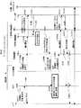
図3はゲートウェイシステムの制御装置の構成図である。制御装置(110)は、例えば、プロセッサ装置(111)、記憶装置(116)、電話網インタフェース部(117)、IP網インタフェース部(119)、主信号処理装置インタフェース部(118)を主要なハードウェア構成要素として実現される。制御装置と主信号処理装置がIP網を介して接続される場合はIP網インタフェース部が主信号処理装置インタフェース部を兼ねる場合も考えられる。
【0020】
プロセッサ装置(111)は、基本制御部(112)、タイマ管理部(113)、リソース管理部(114)、主信号処理装置制御部(115)の機能ブロックを主要要素として構成される。基本制御部(112)は各装置とのインタフェースを実現するとともにタイマ管理部、リソース管理部、主信号処理装置制御部が実装されたソフトウェアまたはハードウェアの実行制御を行う。主信号処理装置制御部(115)は主信号処理装置状態の制御、電話網の信号の中継、サーバ群へのアクセス等の外部装置との通信を実現するアルゴリズムが実装される。リソース管理部(114)は制御装置にて主信号処理装置の通信状態の管理を実現するアルゴリズムが実装され、記憶装置(116)内の状態管理テーブルの参照、更新機能を実現する。タイマ管理部(113)は制御装置内のタイマ(1131)を制御し、主信号装置状態、閉塞/迂回制御のタイマ監視を実現するアルゴリズムが実装されている。上記機能ブロックを構成するモジュールは、記憶装置上に記憶しておき、プロセッサ装置が上記モジュールを実行する際にはプロセッサ装置上のメモリに読み込んで動作させることを可能とする。
【0021】
図4はゲートウェイシステムの主信号処理装置の構成図である。主信号処理装置(120)は例えば、プロセッサ装置(121)、記憶装置(124)、IP網インタフェース部(125)、回線インタフェース部(127)、制御装置インタフェース部(126)を主要なハードウェア構成要素として実現される。制御装置と主信号処理装置がIP網を介して接続される場合はIP網インタフェース部が制御装置インタフェース部を兼ねる場合も考えられる。
【0022】
プロセッサ装置(121)は、基本制御部(122)、インタフェース状態管理部(123)、タイマ(129)、タイマ管理部(128)の機能ブロックを主要要素として構成される。基本制御部(122)は各装置とのインタフェースを実現するとともにインタフェース状態管理部、タイマ管理部の実行制御を行う。インタフェース状態管理部(123)は制御装置(110)より送られてくる制御信号より記憶装置(124)内の管理テーブルの参照・更新機能をもち、主信号処理装置内の回線/IP網インタフェース状態の管理を行うアルゴリズムを実装する。タイマ管理部(128)は主信号処理装置内のタイマ(129)を制御し、IP網インタフェースからの応答パケットのタイマ監視を実現するアルゴリズムが実装されている。上記機能ブロックを構成するモジュールは、記憶装置上に記憶しておき、プロセッサ装置が上記モジュールを実行する際にはプロセッサ装置上のメモリに読み込んで動作させることを可能とする。
【0023】
電話網よりゲートウェイシステムへの接続要求が発生した場合、電話網(101)より呼制御信号を受信した制御装置(110)は呼制御信号内の情報に基づき主信号処理装置(120)に対してアクセス制御を行う。制御装置が主信号処理装置を制御するために認証・課金サーバ等のサーバ群へのアクセスを必要とする場合は、制御装置のIP網インタフェース部(119)を介して、サーバ群に対してアクセスを行う。主信号処理装置は制御装置より送出される制御信号に基づき電話網インタフェースおよびIP網インタフェースのパスを開きユーザ端末とIP網との接続および電話網とIP網との間のインタフェース変換処理を行う。主信号処理装置がユーザ端末をIP網に接続するために認証・課金サーバ等のサーバ群へのアクセスが必要な場合は、例えば、RADIUSプロトコルによるユーザ認証を実施する。
【0024】
図5は制御装置から電話網に対して迂回指示を行う契機となる障害のケースを示している。ケース(1)は制御装置から被制御対象である1つまたは複数の主信号処理装置への制御アクセス経路に障害があるケースを示す。ケース(2)は主信号処理装置からサーバ群へのアクセス経路に障害があるケースを示す。ケース(3)は制御装置からサーバ群へのアクセス経路に障害があるケースを示す。ケース(4)は制御装置からISP網へのアクセス経路に障害があるケースを示す。ケース(5)は主信号処理装置からISP網へのアクセス経路に障害があるケースを示す。ケース(6)は主信号処理装置に障害があるケースを示す。
【0025】
上記ケース(1)から(6)の障害については、障害個所および障害契機によりゲートウェイシステムから電話網に対して行う迂回指示方法を切り替えることが可能である。
【0026】
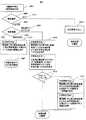
図6はゲートウェイシステム(103)にてIP網障害を検出または網管理装置を含むサーバ群(130)から障害通知を受信した場合における電話網への迂回指示方法の選択フローの例を示している。
【0027】
ゲートウェイシステムはIP網障害を検出または網管理装置を含むサーバ群より障害通知を受信した場合(S601)、その障害検出個所の判別を行い(S602)、ケース(1)、(2)、(3)、(6)の場合(S603)には、さらに障害検出契機の判別を行い(S604)、障害検出契機が障害発生時(S605)の場合には、該当制御装置(110)または主信号処理装置(120)を介しての接続不可であると判断し、後に示す迂回指示方法1を用いて、制御装置より電話網(101)に対して該当制御装置/主信号処理装置に収容されている回線の閉塞指示を行い(S606)、障害復旧を検出するまでの間該当回線を閉塞する(S607)。
【0028】
電話網からのアクセスを契機に障害が検出された場合(S608)には、電話網からの着信時にアクセスエラーが発生するたびに後に示す迂回指示手順2または迂回指示方法3を用いて電話網に対し正常運用されている別の制御装置/主信号処理装置への回線の迂回を指示した後(S609)、アクセスエラー頻度の計測を行う(S610)。
【0029】
アクセスエラーが制御装置/主信号処理装置に予め設定されたしきい値を越えた場合には、後に示す迂回指示方法4または迂回指示方法5を用いて該当制御装置/主信号処理装置に収容されている回線のタイマ監視による一時閉塞や部分閉塞を行う(S611)。
【0030】
障害個所がケース(4)、(5)の場合(S612)には、迂回指示方法2または迂回指示方法3を用いて電話網からの着信時に着番号/IPアドレス/ドメイン名等の情報より該当経路へのアクセス可否の判定を行い、該当経路へのアクセス不可と判断された場合には電話網に対して迂回指示を行う(S613)。
【0031】
上に示した迂回指示手順1から5を用いることにより、ゲートウェイシステムの一部においてIP網障害が検出されている場合においてもユーザに障害を意識させることなくネットワークとしてサービスを継続することが可能となる。
【0032】
次にケース(1)から(6)の障害を検出する手段の例を示す。
【0033】
ケース(1)の障害を検出する方法1としては、制御装置がその内部に設けられている主信号処理装置への送信バッファ、等内部リソースを監視し、アクセス要求パケットが送出する事ができずに内部リソースがオーバフローを起こしてパケット廃棄するような状況に陥っている事を検出する事によりケース(1)のアクセスで障害が起こっている事を検出する。
【0034】
ケース(1)の障害を検出する方法2としては、制御装置がアクセス要求パケットをIP網に送出した際にタイマ設定を行って応答パケット受信までの時間を監視することにより検出する方法である。タイマ管理部は応答パケットが監視時間内に到着しない場合、または応答パケットが到着するが到着までの時間が著しく遅くなっている事が頻発する場合はケース(1)のアクセスで障害が起こっていると判断する。
【0035】
ケース(1)の障害を検出する方法3としては、IP網内の網管理装置からの通知、または制御装置から網管理装置への問い合わせにより主信号制御装置へのアクセス経路に障害が発生していることを検出する方法である。網管理機能はサーバ類に配備されている場合、ゲートウエイシステム内部に配備されている場合、またはゲートウエイシステムが収容されているLANに収容されている場合が可能である。簡易には、制御装置から主信号制御装置あるいは主信号処理装置へのアクセス経路にあるルータのIP網内のルーティング装置に対してping、あるいは上位レイヤのパケット等により定期的に問い合わせを行い障害を検出する方法や、主信号処理装置あるいはアクセス経路にあるルータ、等のIP網内のルーティング装置、例えばルータから定期的にパケット送出し、制御装置で監視することにより障害を検出する方法も可能である。
【0036】
ケース(1)の障害を検出する方法4としては、制御装置から送出したIPパケットに対してIP網内の装置より送達不可通知を受信して検出する方法である。制御装置はそれぞれの方法で検出したケース(1)のアクセス経路の障害により制御が行えなくなった主信号処理装置への着信呼を他の主信号処理装置に対して迂回が行えるように、後で述べる方法により電話網に迂回指示を行う事によりケース(1)の障害が生じてもネットワークとしてユーザに対してサービスを提供する事が可能となる。
【0037】
ケース(2)の障害を検出する方法1としては、主信号処理装置がその内部に設けているサーバ群への送信バッファ等の内部リソースを監視し、アクセス要求パケットが送出する事ができずに内部リソースがオーバフローを起こしてパケット廃棄するような状況に陥っている事を検出し、制御装置に当該主信号処理装置が使用できなくなっている事を通知する事によりケース(2)のアクセスで障害が起こっている事を検出する。制御装置はその通知を受けて当該主信号処理装置が使用できなくなっている事を検出する事ができる。
【0038】
ケース(2)の障害を検出する方法2としては、主信号処理装置がアクセス要求パケットをIP網に送出した際にタイマ設定を行って応答パケット受信までの時間を監視することにより検出し、その旨を制御装置に通知する方法である。タイマ管理部は応答パケットが監視時間内に到着しない場合、または応答パケットが到着するが到着までの時間が著しく遅くなっている事が頻発する場合はケース(2)のアクセスで障害が起こっていると判断して主信号処理装置から制御装置に通知を行い、制御装置はその通知を受けて当該主信号処理装置が使用できなくなっている事を検出する。
【0039】
ケース(2)の障害を検出する方法3としては、IP網内の網管理装置からの通知、または制御装置から網管理装置への問い合わせにより主信号制御装置からサーバ群へのアクセス経路に障害が発生していることを検出する方法である。網管理機能はゲートウェイシステム内部に配備されている場合、またはゲートウエイシステムが収容されているLANに収容されている場合が可能である。障害の通知は主信号処理装置に対して行われた後、方法1、2と同様に制御装置に通知される場合と、直接制御装置に通知される場合がありうる。簡易には、主信号処理装置からサーバ群あるいはサーバ群へのアクセス経路にあるルータのIP網内のルーティング装置に対してPing、あるいは上位レイヤのパケット等により定期的に問い合わせを行い障害を検出する方法や、サーバ群あるいはアクセス経路にあるルータのIP網内のルーティング装置から定期的なパケット送出し、その定期的なパケットを主信号処理装置で監視することにより障害を検出することも可能である。
【0040】
ケース(2)の障害を検出する方法4としては、主信号処理装置から送出したIPパケットに対してIP網内のルーティング装置より送達不可通知を受信して主信号処理装置で検出し、制御装置に通知する方法である。
【0041】
制御装置はそれぞれの方法で検出したケース(2)のアクセス経路の障害により使用できなくなった主信号処理装置への着信呼を他の主信号処理装置に対して迂回が行えるように、後で述べる方法により電話網に迂回指示を行う事によりケース(2)の障害が生じてもネットワークとしてユーザに対してサービスを提供する事が可能となる。
【0042】
ケース(3)の障害を検出する方法1としては、制御装置がその内部に設けられているサーバ群への送信バッファ等の内部リソースを監視し、アクセス要求パケットが送出する事ができずに内部リソースがオーバフローを起こしてパケット廃棄するような状況に陥っている事を検出する事によりケース(3)のアクセスで障害が起こっている事を検出する。
【0043】
ケース(3)の障害を検出する方法2としては、制御装置がアクセス要求パケットをIP網に送出した際にタイマ設定を行って応答パケット受信までの時間を監視することにより検出する方法である。応答パケットが監視時間内に到着しない場合、または応答パケットが到着するが到着までの時間が著しく遅くなっている事が頻発する場合はケース(3)のアクセスで障害が起こっていると判断する。
【0044】
ケース(3)の障害を検出する方法3としては、IP網内の網管理装置からの通知、または制御装置から網管理装置への問い合わせによりサーバ群へのアクセス経路に障害が発生していることを検出する方法である。網管理機能はゲートウエイシステム内部に配備されている場合、またはゲートウエイシステムが収容されているLANに収容されている場合が可能である。簡易には、制御装置からサーバ群あるいはサーバ群へのアクセス経路にあるルータのIP網内のルーティング装置に対してPing、あるいは上位レイヤのパケット等により定期的に問い合わせを行い障害を検出する方法や、サーバ群あるいはアクセス経路にあるルータのIP網内のルーティング装置から定期的なパケット送出し、その定期的なパケットを制御装置で監視することにより障害を検出する方法も方法の3の実現方法のひとつである。
【0045】
ケース(3)の障害を検出する方法4としては、制御装置から送出したIPパケットに対してIP網内の装置より送達不可通知を受信して検出する方法である。
【0046】
制御装置はそれぞれの方法で検出したケース(3)のアクセス経路の障害により当該制御装置によって電話網からの着信呼の制御が行えなくなった事を検出し、当該制御装置の被制御装置である1つまたは複数の主信号処理装置への着信呼を他の主信号処理装置に対して迂回が行えるように、後で述べる方法により電話網に迂回指示を行う事によりケース(3)の障害が生じてもネットワークとしてユーザに対してサービスを提供する事が可能となる。
【0047】
ケース(4)の障害を検出する方法1としては、制御装置内部のISP網への送信バッファ等の内部リソースを監視し、当該ISP網へのアクセス要求パケットが送出する事ができずに内部リソースがオーバフローを起こしてパケット廃棄のような状況に陥っている事を検出する事によりケース(4)のアクセスで障害が起こっている事を検出する。
【0048】
ケース(4)の障害を検出する方法2としては、制御装置がアクセス要求パケットをIP網に送出した際にタイマ設定を行って応答パケット受信までの時間を監視することにより検出する方法である。応答パケットが監視時間内に到着しない場合、または応答パケットが到着するが到着までの時間が著しく遅くなっている事が頻発する場合はケース(4)のアクセスで障害が起こっていると判断する。
【0049】
ケース(4)の障害を検出する方法3としては、IP網内の網管理装置からの通知、または制御装置から網管理装置への問い合わせにより当該ISP網へのアクセス経路に障害が発生していることを検出する方法である。網管理機能はサーバ群に配備される場合、ゲートウエイシステム内部に配備されている場合、またはゲートウエイシステムが収容されているLANに収容されている場合がある。簡易には、制御装置から当該ISP網あるいは当該ISP網へのアクセス経路にあるルータのIP網内のルーティング装置に対してPing、あるいは上位レイヤのパケット等により定期的に問い合わせを行い障害を検出する方法や、当該ISP網あるいはアクセス経路にあるルータのIP網内のルーティング装置から定期的にパケットを送出し、その定期的なパケットを制御装置で監視することにより障害を検出する方法も方法3の実現方法のひとつである。
【0050】
ケース(4)の障害を検出する方法4としては、制御装置から送出したIPパケットに対してIP網内の装置より送達不可通知を受信して検出する方法である。
【0051】
制御装置はそれぞれの方法で検出したケース(4)のアクセス経路の障害により当該制御装置から当該ISP網に対するアクセスが行えなくなった事を当該ISP網のIPアドレス単位/IPアドレスのネットワークアドレス単位、またはネットワークより上位のアドレス単位に検出、管理し、当該制御装置の被制御装置である1つまたは複数の主信号処理装置を使用する当該単位アドレスへの着信呼を他の主信号処理装置に対して迂回が行えるように、後で述べる方法により電話網に迂回指示を行う事によりケース(4)の障害が生じてもネットワークとしてユーザに対してサービスを提供する事が可能となる。
【0052】
ケース(5)の障害を検出する方法1としては、主信号処理装置内部のISP網への送信バッファ等の内部リソースを監視し、当該ISP網へのアクセス要求パケットが送出する事ができずに内部リソースがオーバフローを起こしてパケット廃棄するような状況に陥っている事を検出し、制御装置に対して通知する事によりケース(5))のアクセスで障害が起こっている事を検出する。
【0053】
ケース(5)の障害を検出する方法2としては、主信号処理装置がアクセス要求パケットをIP網に送出した際にタイマ設定を行って応答パケット受信までの時間を監視することにより検出する方法である。応答パケットが監視時間内に到着しない場合、または応答パケットが到着するが到着までの時間が著しく遅くなっている事が頻発する場合はケース(5)のアクセスで障害が起こっていると判断し、制御装置に通知する方法である。
【0054】
ケース(5)の障害を検出する方法3としては、IP網内の網管理装置からの通知、または主信号処理装置から網管理装置への問い合わせにより当該ISP網へのアクセス経路に障害が発生していることを検出し、制御装置へ通知する方法である。網管理装置からの通知は制御装置に対して直接行われても構わない。
【0055】
網管理機能はサーバ群に配備される場合、ゲートウエイシステム内部に配備されている場合、またはゲートウエイシステムが収容されているLANに収容されている場合がある。簡易には、主信号処理装置から当該ISP網あるいは当該ISP網へのアクセス経路にあるルータのIP網内のルーティング装置に対してPing、あるいは上位レイヤのパケット等により定期的に問い合わせを行い障害を検出する方法や、当該ISP網あるいはアクセス経路にあるルータのIP網内のルーティング装置から定期的なパケット送出を行い、その定期的なパケットを主信号処理装置で監視することにより障害を検出する方法も方法3の実現方法のひとつである。
【0056】
ケース(5)の障害を検出する方法4としては、主信号処理装置から送出したIPパケットに対してIP網内の装置より送達不可通知を受信して検出し、制御装置に通知する方法である。
【0057】
制御装置はそれぞれの方法で検出したケース(5)のアクセス経路の障害により当該制御装置から当該ISP網に対するアクセスが行えなくなった事を当該ISP網のIPアドレス単位/IPアドレスのネットワークアドレス単位、またはネットワークより上位のアドレス単位に検出、管理し、当該制御装置の被制御装置である1つまたは複数の主信号処理装置を使用する当該管理単位のIPアドレスに対する着信呼を他の主信号処理装置に対して迂回が行えるように、後で述べる方法により電話網に迂回指示を行う事によりケース(5)の障害が生じてもネットワークとしてユーザに対してサービスを提供する事が可能となる。
【0058】
ケース(6)の障害を検出する方法としては主信号処理装置の障害部位によって異なる。
【0059】
制御装置とのインタフェースまたは主信号処理装置の内部主装置に障害が生じた場合にはケース(1)の方法1、2、3により検出する事が可能である。サーバ群とのインタフェースで障害が生じた場合にはケース(2)の方法1、2、3により検出する事が可能である。ISP網とのインタフェースで障害が生じた場合にはケース(5)の方法1、2、3により検出する事が可能である。電話網とのインタフェースで障害が生じた場合には主信号処理装置内部にて装置状態を監視し、回線障害、装置障害を検出した事を契機に制御装置に通知する事により検出が可能である。
【0060】
制御装置は既に述べた障害検出方法により障害を検出した場合には、それぞれ検出方法に応じた動作により電話網に対して迂回を指示する。電話網とのインタフェース障害を検出した場合には障害を検出した回線に該当する着信呼を当該主信号処理装置の他の電話網とのインタフェース、または他の主信号処理装置に対して迂回を行なうよう電話網に指示する事によりケース(6)の障害が生じてもネットワークとしてユーザに対してサービスを提供する事が可能となる。
【0061】
以下に電話網への迂回指示方法の実施例について述べる。
【0062】
迂回指示方法1の例としてケース(2)の障害を方法3の手段で検出した場合の迂回指示方法1の手順の例を図7に、図8にシーケンス図の例を示す。
【0063】
図7および図8では制御装置と電話網がNo.7共通線で接続接続されている場合において、電話網に対して回線が使用できない事をITUーT勧告ISUPの閉塞信号により指示する例を示している。
【0064】
主信号処理装置1(120−a)のプロセッサ装置(121)において、サーバ群との間での状態問い合わせパケット(S801)に対する応答パケット(S802)が到着しないことからケース(2)の障害であることを検出し(701)、制御装置1(110−a)に対して主信号処理装置1が使用不可であることを通知する(702、S803)。制御装置1のプロセッサ装置(111)および電話網インタフェース部(117)は、電話網(101)との間でISUPの閉塞信号であるBLO(S807)、BLA(S808)を送受することにより主信号処理装置1に収容した回線群1の閉塞を行う(703、S804)。電話網は制御装置(110ーa)から回線群1(160−a)が閉塞された事により(S809)、ユーザ(150)が発信したSETUP(S810)の着信番号によるルーティング先回線群1、2、3のうち回線群2、3のみをルーティング先として選択し(704−a、704−b)、ユーザへCALL PROC(S812)を、制御装置1へは着信回線群2、3が選択されたIAM(S811)を送出するため、ユーザにはケース(2)の障害を意識させずにネットワークとしてサービスを提供し続ける事が可能となる。
【0065】
制御装置1はルーティング先として選択された主信号処理装置3(120−b)との間で着信処理を(705、S813〜S816)、また電話網へはACM(S817)、ANM(S818)を送出してIP網と接続されたことを通知する。電話網はユーザにCONNを送出し(S819)、迂回接続を実現し、通信状態となる(S820)。
【0066】
次に主信号処理装置3はサーバ群との間でユーザとISP網との接続性確認を行い(706)、正常応答の場合、主信号処理装置3を介してユーザとISP網との相互接続が確立される(707)。
【0067】
ケース(3)の障害では当該制御装置の制御する主信号処理装置はすべて使用できない為、共通線の制御リンクをリンクレベルまたは物理レベルにて使用不可の状態にすることにより同様の効果を得る事が可能である。
【0068】
ゲートウェイシステムと電話網がISDN加入者線で接続されている場合で、Dchと使用できない回線が別のISDN回線に収容されている場合にはレイヤ1能力を消失している旨をITU−T勧告I.430およびI.431に従ってレイヤ1信号または電気的に信号を送らない、等により電話網側に通知する方法により同様の効果が得られる。ゲートウエイシステムと電話網がISDN加入者線で接続されている場合でケース(3)の障害の場合は、当該制御装置の制御する主信号処理装置はすべて使用できない為、Dchの制御リンクをリンクレベルまたは物理レベルにて使用不可の状態にする事により同様の効果を得る事が可能である。
【0069】
迂回指示方法2の例として、ケース(4)の障害を方法3の手段によって検出した場合の迂回指示方法2の手順の例を図9に、図10にシーケンス図の例、図11にテーブル設定図の例を示す。
【0070】
また、迂回指示方法3の例としてケース(5)の障害を方法3の手順によって検出した場合の迂回指示方法3の手順の例を図12に、図13にシーケンス図の例、図14にテーブル設定図の例を示す。
【0071】
ケース(4)、(5)の方法3で検出する障害は障害が生じた時点で制御装置が検出し得る障害であるが、該当する制御装置、及び主信号処理装置に関連する回線と管理されているIPアドレス、またはIPアドレスの上位アドレス単位に依存する為、電話網に対しては呼毎に迂回指示を行う必要がある。そのため制御装置または主信号処理装置は制御装置・主信号処理装置の記憶装置内(116、124)にIPアドレス、またはIPアドレスの上位アドレス単位にテーブルを備え、ISP網への宛先IPアドレスが管理された障害経路に一致する場合のみ迂回を指示する。
【0072】
図9、10、11では制御装置と電話網がNo.7共通線により接続されており、電話網は回線群1、2、3に共通してルーティングする1つまたは複数の着番号以外に回線群1、2、3それぞれに対してのみルーティング可能な1つまたは複数の着番号をトランスレータによって備えいる。この場合においてケース(4)の方法3で検出した時に他の制御装置/主信号処理装置に迂回可能な着信番号先に再発信することにより迂回指示を行なう場合の例を示す。
【0073】
制御装置1(110−a)のプロセッサ装置(111)において、ISP網または他のゲートウェイシステム(140)に対する状態問い合わせパケット(S1001)に対する応答パケット(S1002)が到着しないことからケース(4)の障害により、当該ISP網/ゲートウェイシステムへの経路がないことを認識し(901)、制御装置の記憶装置内(116)内の経路管理テーブル(116−1)の経路状態を障害に書き換える(S1003)。次に電話網(101)より制御装置1に接続要求が行われると(902−a、902−b、S1006〜S1009)、制御装置1のプロセッサ装置は着信番号情報よりサーバ群へ接続先のIPアドレス情報の取得を要求を行い(903、S1010、S1011)、制御装置1は取得したIPアドレスより制御装置の記憶装置内の経路管理テーブルを参照することにより当該IPアドレスへの経路がないことを認識し(904)、同記憶装置内の迂回先番号管理テーブル(116−2)を参照してケース(4)の障害時の場合の迂回先番号を取得し(S1012)、電話網に対して迂回先番号を通知する(S1013)。迂回先番号を受信した電話網は迂回先である制御装置2に対して接続要求を行い(905、S1014)、制御装置2/主信号処理装置2はサーバ群およびISP網/他ゲートウェイへのアクセスが正常に行われることにより(906、S1015、S1016、S1018、S1019)、電話網との接続が行われ(S1017、S1020、S1021)、ユーザ(150)とISP網とが通信状態となり(S1022)、制御装置2および主信号処理装置2を介してユーザ(150)とISP/他ゲートウェイシステムとの接続が行われる(907、908)。
【0074】
図11では、IPアドレスが192.168.228.101の経路に対してケース(4)の障害が検出された場合のテーブル参照・更新方法の例を示している。
【0075】
制御装置内記憶装置(116)は制御装置内プロセッサよりケース(4)で192.168.228.101の経路が障害である通知を受けることにより(1101)、ISP網/ゲートウェイシステム経路管理テーブル(116−1)を検索し、192.168.228.101のフィールドの経路状態を障害に書き換える(1102)。
【0076】
次に、ケース(4)において制御装置(110)内プロセッサ装置(111)より192.168.228.101の経路へのアクセスが行われると(1103)、記憶装置(116)の上記テーブルの検索を行い、192.168.228.101の経路が障害であり迂回が必要であることを検出し(1104)、迂回先番号管理テーブルの検索を行い(1106)、ケース(4)の迂回先番号3-3456-7890を読み出す(1105)。
【0077】
ゲートウェイシステムからの迂回指示方法としてITU勧告/TTC標準のピボット手順を起動し、電話網に対して迂回指示を行なう事によっても同様の効果を得る事が可能である。また、制御装置と電話網がISDN加入者線で接続されている場合には迂回先番号に対して着信転送手順を起動する事により同様の効果が得られる。
【0078】
図12、13、14では電話網内にSCPを備えている場合において、ケース(5)の障害を方法3で障害を検出し、ある特定の切断要因を含めた切断信号を電話網側に送出する事により、SCPで管理される迂回先番号に迂回を行なう方法を示す。
【0079】
主信号処理装置1(120−a)のプロセッサ装置(121)において、ISP網または他のゲートウェイシステム(140)に対する状態問い合わせパケット(S1301)に対する応答パケット(S1302)が到着しないことからケース(5)の障害により、当該ISP網/ゲートウェイシステムへの経路がないことを認識し(1201)、主信号処理装置の記憶装置内(124)内の経路管理テーブル(124−1)の経路状態を障害に書き換える(S1303)。
【0080】
次にSCPを介して電話網(101)より制御装置1/主信号処理装置1に接続要求が行われると(1202、S1306〜S1309)、主信号処理装置1のプロセッサ装置は着信番号情報よりサーバ群へ接続先のIPアドレス情報の取得要求を行い(1203、S1310、S1311)、主信号処理装置1は取得したIPアドレスより制御装置の記憶装置内の経路管理テーブルを参照し、当該IPアドレスへの経路がないことを認識し(1204、S1312)、制御装置1に対して経路無しによる受付不可応答を返送し(1205、S1313)、制御装置1は迂回を行う理由表示を設定したRELを電話網に送出する(1206、S1314)。電話網ではSCPにおいて受信した理由表示より着番号の迂回先番号への変換を行い(S1315)、迂回先である主信号処理装置3への着信を行い(1207、S1316、S1317)、主信号処理装置3を介してサーバ群およびISP網/他ゲートウェイ網との接続が行われる(1208〜1210、S1319〜S1325)。
【0081】
図14では、IPアドレスが192.168.228.101の経路に対してケース(5)の障害が検出された場合のテーブル参照・更新方法の例を示している。
【0082】
主信号処理装置内記憶装置(124)は主信号処理装置内プロセッサ装置よりケース(5)で192.168.228.101の経路が障害である通知を受けることにより(1401)、ISP網/ゲートウェイシステム経路管理テーブル(124−1)を検索し、192.168.228.101のフィールドの経路状態を障害に書き換える(1402)。
【0083】
次に、ケース(5)において主信号処理装置内プロセッサより192.168.228.101の経路へのアクセスが行われると(1403)、記憶装置の上記テーブルの検索を行い、192.168.228.101の経路が障害であり迂回が必要であることを検出し(1404)、ルーティング経路が障害であるため着呼受付不可であることを通知する(1405)。
【0084】
本方法(迂回指示方法3)は制御装置と電話網がNo.7共通線で接続されていてもISDNで接続されていても同様の効果を得る事が可能である。
【0085】
ケース(1)、(2)、(3)、(4)、(5)の方法1、2、4で検出する障害は障害が生じた時点ではなく、電話網からの着信が生じた事によるそれぞれのアクセスを契機に検出される。迂回指示は呼毎に行なうことが有効である為、迂回指示方法2、及び3を適用する事が可能である。
【0086】
図15に制御装置と電話網がNo.7共通線で接続されている場合において、ケース(2)の方法2により障害を検出し、迂回指示方法3を適用した場合の手順の例を、図16にシーケンス図の例を示す。
【0087】
本ケースの場合、電話網(101)より制御装置1(110−a)/主信号処理装置1(120−a)に着信が行われ(1501、1502、S1601〜S1604)、主信号処理装置のプロセッサ装置(121)よりサーバ群(130)へのISP網へのIPアドレス取得要求(S1605)に対する応答がタイムアウトすることによりケース(2)の障害を検出し(1503、S1607)、主信号処理装置1から制御装置1に対してサーバアクセス不可による受付不可応答が返送され(1504、S1608)、制御装置1は迂回を行う理由表示が設定されたRELを電話網に返送する(1505、S1609)。以後図13の場合と同様の手順により主信号処理装置3への迂回接続が行われる(1506〜1509、S1610〜S1619)。
【0088】
ケース(1)、(2),(3)の方法1、2、4で検出する障害は、上記に述べたように、呼毎に検出される障害であるが、障害の要因自体はルータの故障、等の様に固定的である場合がありうる。そのため、制御装置においてその障害をケース毎、方法毎に検出したときに設けたカウンタにより障害検出頻度を計測し、設定したしきい値を超えた場合には固定的な障害であると判断して、迂回指示方法1を適用することも可能である。上記ケースの場合、制御装置および主審号処理装置自体の要因による障害ではないため、障害の復旧を検出し、迂回指示を解除する手段が必要となる。迂回指示および迂回指示解除を実現する手段として固定的な障害と判断した経路に対して障害監視タイマを設定し、タイマ起動中の間、迂回指示を行い、タイマ満了後に迂回指示を解除する手段をとることが可能である。
【0089】
これを迂回指示方法4とし、図17に制御装置と電話網がNo.7共通線により接続されている場合において、ケース(3)の方法2により障害を検出し、迂回指示方法1により電話網に対して回線閉塞を指示し、さらに該当経路に対して制御装置内のタイマ管理部(113)にて障害監視タイマを起動し、タイマ満了後に閉塞解除を行なうことにより迂回指示および迂回指示解除を行う例を、図18にシーケンス図の例を、図19にフローの例を示す。
【0090】
制御装置1(110−a)のプロセッサ装置(111)は、ユーザ(150)からの着信(1701)に対して着番号よりサーバ群(130)に対するISP網のIPアドレス取得要求タイムアウトによりケース(3)の障害であることを検出することにより(1702、S1805)、呼の切断が行われた後に(S1807、S1808)、アクセスエラー頻度比較判定を開始し、アクセスエラーが障害しきい値を上回った場合(S1809、S1903)、電話網に対し制御装置1が管理している回線群1、3の回線閉塞指示を行い(1703、S1810、S1811)、閉塞監視タイマを起動する(S1904)。アクセスエラー頻度がしきい値を下回っている場合はアクセスエラーカウンタをカウントアップする(S1905)。回線群1、3閉塞中は回線群2に対して着信が行われ(1704)、制御装置2/主信号処理装置2(110−b)を介して電話網とIP網の接続が行われる(1705、1706、S1812〜S1819)。
【0091】
次に、制御装置1のプロセッサ装置は閉塞監視タイマがタイムアウトすることにより回線群1、3に対して閉塞解除を行い(S1820〜S1822)、回線群1〜3への着信が復旧する(S1823〜S1826)。
【0092】
また、迂回指示および迂回指示解除を実現する手段として、固定的な障害と判断した経路に対して 部分閉塞指示を行った状態で該当経路に対する障害頻度を測定し、制御装置または主審号処理装置で管理しているしきい値を下回った場合に障害復旧と判断し、迂回指示を解除する手段をとることが可能である。これを迂回指示方法5とし、図20に制御装置と電話網がNo.7共通線により接続されている場合において、ケース(3)の方法2により障害を検出し、迂回指示方法5により電話網に対して回線の50%の閉塞を指示し、その後も障害頻度がしきい値を超える場合にさらに50%の閉塞を指示し、障害頻度が閉塞を解除するしきい値を下回った時に、回線の閉塞を一部解除していく事により使用不可の状態から復旧させる場合のネットワーク図の例を、図21にシーケンス図の例を、図22にフローの例を示す。
【0093】
制御装置1(110−a)のプロセッサ装置(111)はユーザ(150、S206)からの着信(2001)に対して着番号よりサーバ群(130)に対するISP網のIPアドレス取得要求タイムアウトによりケース(3)の障害であることを検出することにより(2002、S2105、S2106)、呼の切断が行われた後に(S2107、S2108)、アクセスエラー頻度比較判定を開始し、アクセスエラー頻度が障害検出しきい値を上回った場合(S2109、S2204)、電話網に対し回線群1、3の非閉塞回線の内の50%に対する閉塞指示を行う(2003、S2205)。
【0094】
このとき回線群1、3が部分閉塞状態にあるため一部の着信呼が回線群2へ迂回され(2004)、制御装置2/主信号処理装置2(120−b)を介して電話網とIP網との接続が行われる(2005、2006、S2112〜S2119)。
【0095】
回線群1、3が部分閉塞中に回線群1、3への着信が行われた場合(S2120〜S2121)において、制御装置1からサーバ群へのISP網のIPアドレス取得が正常に行われた場合、プロセッサ装置において再度アクセスエラー頻度比較判定を開始し、アクセスエラー頻度が復旧検出しきい値を下回っている場合は(S2125、S2203)、回線群1、3の閉塞中の回線の閉塞解除指示を行う(S2126、S2127)。
【0096】
ケース(1)、(2)、(3)、(4)、(5)の方法1、2、4で検出する障害については障害が生じた時点でなく、電話網からの着信が生じたことによるそれぞれのアクセスを契機に検出され、迂回指示は呼毎に行うことが有効であるため、迂回指示方法2または迂回指示方法3を用いることが適切である。前記障害がルータやサーバ類といったIP網を構成する装置の固定的障害等の原因により多発する場合には、迂回指示方法4または迂回指示方法5による方法が適切となる。また、ケース(1)、(2)、(3)の方法3で検出する障害については障害が生じた時点で制御装置が検出し得る障害であり、該当する回線に対する着信呼全てに迂回指示を行うことが有効であるため、迂回指示方法1を用いて制御装置より電話網に対して迂回指示を行うことが適切となる。
【0097】
また、ケース(4)、(5)の方法3で検出する障害については障害が生じた時点で制御装置が検出し得る障害であるが該当する制御装置および主信号処理装置に関連する回線と管理されているIPアドレスやネットワークアドレス単位に依存するため、電話網に対しては呼毎に迂回指示を行うことが有効であるため、迂回指示方法2または迂回指示方法3を用いて制御装置より電話網に対して迂回指示を行うことが適切である。
【0098】
以上に述べたケース(1)、(2)、(3)、(4)、(5)の方法1、2、3、4及びケース(6)の障害検出方法と迂回指示方法1、2、3、4、5はそれぞれ組み合わせにより独立して適用可能であり、さまざまな組み合わせで同時にシステムに対して適用されても問題無く発明の効果を得る事が可能である。
【0099】
【発明の効果】
本発明のインタネットゲートウェイシステムにおける迂回制御方式を利用することで例えば以下の効果が生じる。
【0100】
(1)電話網よりIP網への接続を行う際にIP網インタフェース状態に合わせたゲートウェイ装置の接続制御を行うことが可能となり、リモートアクセスサービスにおける通信品質を向上させることができる。
【0101】
(2)同一エリア内に複数のゲートウェイ装置が存在する場合にリモートアクセスユーザにIP網インタフェース状態に合わせた最適な接続先を選ぶことが可能となる。
【図面の簡単な説明】
【図1】本発明におけるゲートウェイシステムを介した電話網とIP網の網間相互接続の構成、及びゲートウェイシステムの主信号処理装置からサーバ類へのアクセスを行なう場合の手順を示した図である。
【図2】本発明におけるゲートウェイシステムを介した電話網とIP網の網間相互接続の構成、及びゲートウエイシステムの制御装置からサーバ類へのアクセスを行なう場合の手順を示した図である。
【図3】本発明における制御装置の構成を示した図である。
【図4】本発明における主信号処理装置の構成を示した図である。
【図5】本発明におけるゲートウェイシステムを介した電話網とIP網の網間相互接続時の障害ケースを示した図である。
【図6】本発明におけるゲートウェイシステムを介した電話網とIP網の網間相互接続時の障害ケースにおける迂回指示方法の選択フローを示した図である。
【図7】本発明におけるケース(2)の障害を方法3で検出し、迂回指示方法1で迂回を行なう場合の手順を示す図である。
【図8】本発明におけるケース(2)の障害を方法3で検出し、迂回指示方法1で迂回を行なう場合のシーケンスを示す図である。
【図9】本発明におけるケース(4)の障害を方法3で検出し、迂回指示方法2で迂回を行なう場合の手順を示す図である。
【図10】本発明におけるケース(4)の障害を方法3で検出し、迂回指示方法2で迂回を行なう場合のシーケンスを示す図である。
【図11】本発明におけるケース(4)の障害を方法3で検出する場合の、装置内部での手順を示す図である。
【図12】本発明におけるケース(5)の障害を方法3で検出し、迂回指示方法3で迂回を行なう場合の手順を示す図である。
【図13】本発明におけるケース(5)の障害を方法3で検出し、迂回指示方法3で迂回を行なう場合のシーケンスを示す図である。
【図14】本発明におけるケース(5)の障害を方法3で検出する場合の、装置内部での手順を示す図である。
【図15】本発明におけるケース(2)の障害を方法2で検出し、迂回指示方法3で迂回を行なう場合の手順を示す図である。
【図16】本発明におけるケース(2)の障害を方法2で検出し、迂回指示方法3で迂回を行なう場合のシーケンスを示す図である。
【図17】本発明におけるケース(3)の障害を方法2で検出し、迂回指示方法4で迂回を行なう場合の手順を示す図である。
【図18】本発明におけるケース(3)の障害を方法2で検出し、迂回指示方法4で迂回を行なう場合のシーケンスを示す図である。
【図19】本発明におけるケース(3)の障害を方法2で検出し、迂回指示方法4で迂回を行なう場合のフローを示す図である。
【図20】本発明におけるケース(3)の障害を方法2で検出し、迂回指示方法5で迂回を行なう場合の手順を示す図である。
【図21】本発明におけるケース(3)の障害を方法2で検出し、迂回指示方法5で迂回を行なう場合のシーケンスを示す図である。
【図22】本発明におけるケース(3)の障害を方法2で検出し、迂回指示方法5で迂回を行なう場合のフローを示す図である。
【符号の説明】
103・・・ゲートウェイシステム
110・・・制御装置
120・・・主信号処理装置[0001]
BACKGROUND OF THE INVENTION
The present invention relates to a connection method between a telephone network and an IP network (Internet protocol network), a failure detection method, and a detour control method. The present invention particularly relates to a telephone that detects a failure of an IP network interface of a gateway device and issues a circuit blockage or detour instruction to the preceding telephone network in an Internet gateway system composed of a signaling gateway / media gateway control device and a gateway device. The present invention relates to a connection method between a network and an IP network.
[0002]
[Prior art]
Currently, as means for detecting a failure between nodes in a telephone network, a common line signal link state monitoring with an opposite node in an inter-network interface, a frame bit monitoring of a communication line, and a network side in a user / network interface As a means for notifying each node constituting the network of a failure or congestion, or as a detour instruction, the network interface No. 2 is monitored. 7 Common line signal failure notification, detour instruction by common line signal message transfer unit (MTP: Message Transfer Part), blocking instruction by call line blocking signal by ISDN user part (ISUP: ISDN User Part), and TTC ( Telecommunication Technology Commitee: (Telecommunication Technology Committee))) A means for performing a detour instruction by a standard redirection procedure or an ITU-T (International Telecommunication Union) recommendation / TTC standard pivot procedure is realized.
[0003]
As for the user / network interface, there is no means to notify the telephone network of a failure or a detour instruction from the user side device including the gateway device to the IP network, and the network side monitoring on the network side, detour by call forwarding, etc. Has been done. In addition to this, when the incoming number at the service control point (SCP) in the IN (Intelligent Network Internetwork Interface) procedure is converted as a means that can be bypassed, the converted number is switched depending on the state of the network. In some cases, there is a means for performing control equivalent to detouring.
[0004]
On the other hand, as a means for detecting a failure between nodes in an IP network, a message such as an Internet Control Message Protocol (ICMP) ping specified by RFC (Request for Comments) 792 of IETF (Internet Engineering Task Force) between opposing nodes. For detecting a congestion / failure with an opposite node by transmitting / receiving a network, and a device of each node constituting a network by a network management device such as an SNMP (Simple Network Management Protocol) manager or a gatekeeper defined by RFC1157 There is a way to collect state. In addition, as a method of notifying a failure or congestion or giving a detour instruction, a router, or a network management device such as an SNMP manager or a gatekeeper, RIP (Routing Information Protocol) defined by RFC 2453, OSPF (Open Shortest Path defined by RFC 2328) Fast), and a routing instruction is distributed by delivering routing information to each node constituting a network using a dynamic routing protocol such as BGP (border gateway protocol) defined in RFC1771.
[0005]
[Problems to be solved by the invention]
In a service configuration in which a telephone network and an IP network are interconnected via a gateway system composed of a plurality of gateway devices sharing a plurality of lines with one or a plurality of called numbers, the telephone network and the IP network The method of detecting the failure in each network and performing the detour control is realized as described above. However, since the failure / congestion in the IP network cannot be recognized in the telephone network, the same called number is used. Even if there is a line group that can receive calls normally, incoming calls are made to the line group that uses the routing route that is an obstacle in the IP network, causing call loss and communication quality degradation. It becomes.
[0006]
An object of the present invention is to detect a failure of a device in a gateway system and an IP network by the gateway system in a service configuration in which the telephone network and the IP network are interconnected via a gateway system, and instruct the telephone network to bypass Accordingly, it is an object of the present invention to provide a gateway and a detour control method capable of avoiding selection of a line group using the failure path and ensuring connection quality in an interconnection service between a telephone network and an IP network.
[0007]
[Means for Solving the Problems]
In the present invention, as one of means for detecting an IP network interface failure or congestion in the gateway system, the gateway system monitors the number of packets remaining in the gateway system and internal resources, and accesses the gateway system and the IP network. The function of detecting the line status for the connection from the telephone network to the IP network is detected by detecting the failure state.
[0008]
In addition, the gateway device monitors the response time from the server when an IP packet is sent to various servers in the IP network for authentication / billing and acquisition of IP address information. It has a function of detecting a network failure / congestion with respect to the connection from the gateway system to the IP network by measuring the delay state of the response time from the request transmission.
[0009]
Further, the gateway system receives or inquires about failure information in the IP network from the gatekeeper device or network management device, so that packets can be sent to each node constituting the IP network such as a server group and a router. And has a function of detecting a line state for connection from the telephone network to the IP network.
[0010]
Further, the gateway system has a function of detecting a network failure with respect to the connection from the gateway system to the IP network by analyzing information received from the nodes constituting the IP network, such as routers, that is not routable for a specific route.
[0011]
Further, according to the present invention, the gateway system that detects a network failure or congestion when connecting to the IP network by the above procedure causes a failure to interwork the telephone network to the IP network when the failure / congestion is detected. As a means of restricting connection to devices in the gateway system where the problem occurs and instructing detours to other devices, it is notified that the line interface with the telephone network is unusable, and the telephone network This function has a function of prompting detouring to a line that does not interfere with access to the IP network without using a network.
[0012]
Furthermore, the present invention has a function of notifying the telephone network that the line is unusable, detecting that the failure has disappeared, and notifying that the line has become usable. In addition, when a failure is detected for each call, it has a function of notifying the telephone network that the line is unusable depending on the frequency of failure, and a function of notifying use cancellation by a timer. In addition, when a failure is detected for each call, it is notified to the telephone network that some lines cannot be used due to the failure frequency, and the failure frequency at the time of incoming calls to the remaining lines is monitored. It has a function of detecting recovery from a failure and notifying the telephone network of cancellation of use.
[0013]
The gateway system and the telephone network manage the called numbers that can be routed for each device in the gateway system in the group of lines accommodated, and the gateway system and the telephone network can be diverted to a usable line. It has a function of actively making a detour to the telephone network by instructing the telephone number to the telephone network. Alternatively, by instructing that the call can be bypassed from the gateway system to the telephone network, the detour function using the SCP or the like in the telephone network is used for each available line for each call. Has a function to bypass.
[0014]
DETAILED DESCRIPTION OF THE INVENTION
FIG. 1 and FIG. 2 are examples of a configuration diagram of interconnection between a telephone network and an IP network (Internet protocol) via a gateway system according to the present invention. The telephone network (101) and the IP network (102) are interconnected via a gateway system (103) composed of a control device (110-a, b) and a main signal processing device (120-a, b). The
[0015]
The IP network includes a gateway system, a LAN that accommodates the gateway system, a LAN that accommodates servers, and the Internet network.
[0016]
The telephone network (101) and the control device (110-a, b) are the ISDN user / network interface signal channel (Dch) or the network connection interface No. 7 common line signals are connected, and the telephone network (101) and the main signal processing device (120-a, b, 110-b) are ISDN Bch, H0ch, H1ch, or SDH (Synchronous Digital Hierarchy), 2M TTC, T1. , E1 etc. are connected by a line interface. Control signals from the telephone network (101) are subjected to call processing signal control processing by the control device (110-a, b), and call processing control is performed on the main signal processing device (120-a, b, 110-b). I do. The control device and the main signal processing device may be physically distributed, or may be accommodated in the same device as the control device (110-b). It is also possible to control a plurality of main signal processing devices arranged in a distributed manner such as the main signal processing device (120-b) by one control device (110-a, 110-b). In the figure, the user (150) sends the incoming call number routed by the telephone network (101) to the line group accommodated by the main
[0017]
When the control device receives a connection request from the telephone network, either or both of the control device and the main signal processing device access the authentication / billing / address management server to acquire an access IP address, perform user authentication, etc. After that, the ISP network (Internet service provider network) and other gateway systems are accessed. As an access procedure to the authentication / billing server, for example, RADIUS (Remote Authentication Dial In User Service) defined by RFC2138, 2139 is used. Further, as an access IP address acquisition unit, for example, IPCP (Internet Protocol Control Protocol) defined by RFC1332 of IETF is used.
[0018]
In FIG. 1, the control device 1 (110-a) controls the main signal processing device 1 (120-a), and the main signal processing device 1 (120-a) accesses the servers (130) for control to perform ISP. FIG. 2 shows an example in which the main signal from the calling user is accessed to the network / other gateway system (140) (hereinafter simply referred to as ISP network). FIG. 2 shows that the control device (110-a) controls the servers (130). For controlling the main signal processing device (120-a) and accessing the ISP network (140) for control from the main signal processing device (120-a) to the ISP network (140). An example of performing access is shown.
[0019]
FIG. 3 is a block diagram of the control device of the gateway system. The control device (110) includes, for example, a processor device (111), a storage device (116), a telephone network interface unit (117), an IP network interface unit (119), and a main signal processing device interface unit (118). It is realized as a hardware component. When the control device and the main signal processing device are connected via the IP network, the IP network interface unit may also serve as the main signal processing device interface unit.
[0020]
The processor device (111) is composed mainly of functional blocks of a basic control unit (112), a timer management unit (113), a resource management unit (114), and a main signal processing device control unit (115). The basic control unit (112) realizes an interface with each device and performs execution control of software or hardware in which a timer management unit, a resource management unit, and a main signal processing device control unit are mounted. The main signal processing device control unit (115) is implemented with an algorithm that realizes communication with an external device such as control of the state of the main signal processing device, relay of a signal of a telephone network, access to a server group, and the like. The resource management unit (114) is implemented with an algorithm for managing the communication state of the main signal processing device in the control device, and realizes a function of referring to and updating the state management table in the storage device (116). The timer management unit (113) controls the timer (1131) in the control device, and an algorithm for realizing timer monitoring of the main signal device state and blocking / detour control is implemented. The modules constituting the functional block are stored in a storage device, and when the processor device executes the module, it can be read into the memory on the processor device and operated.
[0021]
FIG. 4 is a block diagram of the main signal processing device of the gateway system. The main signal processing device (120) includes, for example, a processor device (121), a storage device (124), an IP network interface unit (125), a line interface unit (127), and a control device interface unit (126). Realized as an element. When the control device and the main signal processing device are connected via the IP network, the IP network interface unit may also serve as the control device interface unit.
[0022]
The processor device (121) is composed mainly of functional blocks of a basic control unit (122), an interface state management unit (123), a timer (129), and a timer management unit (128). The basic control unit (122) realizes an interface with each device and controls the execution of the interface state management unit and the timer management unit. The interface state management unit (123) has a reference / update function of the management table in the storage device (124) from the control signal sent from the control device (110), and the line / IP network interface state in the main signal processing device. Implement an algorithm to manage The timer management unit (128) controls the timer (129) in the main signal processing device and implements an algorithm for realizing timer monitoring of response packets from the IP network interface. The modules constituting the functional block are stored in a storage device, and when the processor device executes the module, it can be read into the memory on the processor device and operated.
[0023]
When a connection request from the telephone network to the gateway system is generated, the control device (110) that has received the call control signal from the telephone network (101) sends a request to the main signal processing device (120) based on the information in the call control signal. Perform access control. When the control device requires access to a server group such as an authentication / billing server in order to control the main signal processing device, the server group is accessed via the IP network interface unit (119) of the control device. I do. The main signal processing unit opens a telephone network interface and an IP network interface based on a control signal sent from the control unit, and performs a connection between the user terminal and the IP network and an interface conversion process between the telephone network and the IP network. When the main signal processing device needs to access a server group such as an authentication / billing server in order to connect the user terminal to the IP network, for example, user authentication is performed by the RADIUS protocol.
[0024]
FIG. 5 shows a failure case that triggers a detour instruction from the control device to the telephone network. Case (1) shows a case where there is a failure in the control access path from the control device to one or more main signal processing devices to be controlled. Case (2) shows a case where there is a failure in the access path from the main signal processing device to the server group. Case (3) shows a case where there is a failure in the access path from the control device to the server group. Case (4) shows a case where there is a failure in the access path from the control device to the ISP network. Case (5) shows a case where there is a failure in the access path from the main signal processing device to the ISP network. Case (6) shows a case where the main signal processing device is faulty.
[0025]
For the failures in the above cases (1) to (6), it is possible to switch the detour instruction method performed from the gateway system to the telephone network according to the location of failure and the failure trigger.
[0026]
FIG. 6 shows an example of a selection flow of a detour instruction method to the telephone network when an IP network failure is detected in the gateway system (103) or a failure notification is received from the server group (130) including the network management device. .
[0027]
When the gateway system detects an IP network failure or receives a failure notification from the server group including the network management device (S601), it determines the location of the failure detection (S602), and cases (1), (2), (3 ) And (6) (S603), the failure detection trigger is further determined (S604). If the failure detection trigger is when a failure occurs (S605), the corresponding control device (110) or main signal processing is performed. It is determined that connection via the device (120) is impossible, and the control device is accommodated in the corresponding control device / main signal processing device with respect to the telephone network (101) using the
[0028]
If a failure is detected upon access from the telephone network (S608), every time an access error occurs when an incoming call is received from the telephone network, the
[0029]
When the access error exceeds a threshold value preset in the control device / main signal processing device, it is accommodated in the corresponding control device / main signal processing device using the detour instruction method 4 or the
[0030]
If the fault location is case (4), (5) (S612), it is applicable from the information such as the called number / IP address / domain name when receiving from the telephone network using the
[0031]
By using the
[0032]
Next, an example of means for detecting failures in cases (1) to (6) is shown.
[0033]
As a
[0034]
[0035]
As a
[0036]
Method 4 for detecting a failure in case (1) is a method for detecting by detecting a delivery failure notification from a device in the IP network for an IP packet sent from the control device. In order to allow the incoming call to the main signal processing device that can no longer be controlled due to the failure of the access path in the case (1) detected by each method, the control device can bypass the other main signal processing device later. By providing a detour instruction to the telephone network by the method described, it is possible to provide a service to the user as a network even if the failure in case (1) occurs.
[0037]
As a
[0038]
As a
[0039]
As a
[0040]
As a method 4 for detecting a failure in case (2), a non-delivery notification is received from a routing device in the IP network for an IP packet sent from the main signal processing device, and detected by the main signal processing device. It is a method to notify.
[0041]
The control device will be described later so that an incoming call to the main signal processing device that can no longer be used due to an access path failure in case (2) detected by each method can be bypassed to other main signal processing devices. By providing a detour instruction to the telephone network by the method, it becomes possible to provide a service to the user as a network even if a failure in case (2) occurs.
[0042]
As a
[0043]
[0044]
[0045]
A method 4 for detecting a failure in case (3) is a method for detecting the IP packet sent from the control device by receiving a non-delivery notice from the device in the IP network.
[0046]
The control device detects that the control device cannot control the incoming call from the telephone network due to the failure of the access path detected in each method (3), and is a controlled device of the
[0047]
As a
[0048]
[0049]
As a
[0050]
Method 4 for detecting a failure in case (4) is a method for detecting by receiving a non-delivery notice from an apparatus in the IP network for an IP packet transmitted from the control apparatus.
[0051]
The control device indicates that the access to the ISP network from the control device cannot be performed due to the failure of the access path in the case (4) detected by each method, or the IP address unit of the ISP network / the network address unit of the IP address, or An incoming call to the unit address that is detected and managed in an address unit higher than the network and uses one or more main signal processing devices that are controlled devices of the control device is sent to other main signal processing devices. By providing a detour instruction to the telephone network by a method described later so that detouring can be performed, it becomes possible to provide a service to the user as a network even if a failure in case (4) occurs.
[0052]
As a
[0053]
As
[0054]
As a
[0055]
The network management function may be deployed in a server group, deployed in a gateway system, or accommodated in a LAN in which the gateway system is accommodated. For simplicity, the main signal processing device periodically inquires the routing device in the IP network of the router in the access path to the ISP network or the ISP network by using Ping or a higher layer packet, etc. A method for detecting a failure by periodically sending packets from a routing device in the ISP network or an IP network of a router on an access path and monitoring the periodic packet with a main signal processing device Is also one method for realizing
[0056]
Method 4 for detecting a failure in case (5) is a method of receiving and detecting a non-delivery notice from a device in the IP network for the IP packet sent from the main signal processing device, and notifying the control device. .
[0057]
The control device indicates that the access to the ISP network from the control device cannot be performed due to the failure of the access path in the case (5) detected by each method, or the IP address unit of the ISP network / the network address unit of the IP address, or An incoming call for the IP address of the management unit that uses one or more main signal processing devices that are detected and managed in an address unit higher than the network and is a controlled device of the control device is sent to another main signal processing device In order to be able to make a detour, by giving a detour instruction to the telephone network by a method described later, it becomes possible to provide a service to the user as a network even if a failure in case (5) occurs.
[0058]
The method for detecting the failure in case (6) differs depending on the failure part of the main signal processing device.
[0059]
When a failure occurs in the interface with the control device or the internal main device of the main signal processing device, it can be detected by the
[0060]
When the control device detects a failure by the above-described failure detection method, the control device instructs the telephone network to detour by an operation corresponding to the detection method. When an interface failure with the telephone network is detected, an incoming call corresponding to the line where the failure is detected is diverted to an interface with the other telephone network of the main signal processing device or another main signal processing device. By instructing the telephone network, it is possible to provide a service to the user as a network even if a failure in case (6) occurs.
[0061]
An embodiment of a detour instruction method for the telephone network will be described below.
[0062]
As an example of the
[0063]
7 and 8, the control device and the telephone network are No. 7 shows an example of instructing that the line cannot be used for the telephone network by the block signal of the ITU-T recommendation ISUP when the connection is connected with 7 common lines.
[0064]
In the processor device (121) of the main signal processing device 1 (120-a), the response packet (S802) to the status inquiry packet (S801) with the server group does not arrive, which is a failure of the case (2). (701), and notifies the control device 1 (110-a) that the main
[0065]
The
[0066]
Next, the main
[0067]
Since the main signal processor controlled by the controller cannot be used in the failure of case (3), the same effect can be obtained by disabling the common line control link at the link level or physical level. Is possible.
[0068]
ITU-T recommendation that if the gateway system and the telephone network are connected by ISDN subscriber line and the line that cannot be used for Dch is accommodated in another ISDN line, the
[0069]
As an example of the
[0070]
Further, as an example of the
[0071]
The failure detected by
[0072]
9, 10 and 11, the control device and the telephone network are No. 7 are connected by a common line, and the telephone network can be routed only to each of the
[0073]
Since the response packet (S1002) to the status inquiry packet (S1001) for the ISP network or other gateway system (140) does not arrive in the processor device (111) of the control device 1 (110-a), the failure of the case (4) Thus, it is recognized that there is no route to the ISP network / gateway system (901), and the route state in the route management table (116-1) in the storage device (116) of the control device is rewritten as a failure (S1003). . Next, when a connection request is made to the
[0074]
FIG. 11 shows an example of a table reference / update method when a failure in case (4) is detected for the route with the IP address 192.168.228.101.
[0075]
The storage device (116) in the control device receives a notification that the route of 192.168.228.101 is faulty in case (4) from the processor in the control device (1101), and the ISP network / gateway system route management table (116-1) And the path state in the field of 192.168.228.101 is rewritten as a failure (1102).
[0076]
Next, in the case (4), when the processor device (111) in the control device (110) accesses the path 192.168.228.101 (1103), the above table of the storage device (116) is searched, and 192.168 It detects that the route of .228.101 is faulty and needs to be bypassed (1104), searches the bypass destination number management table (1106), and reads the bypass destination number 3-3456-7890 of case (4) ( 1105).
[0077]
The same effect can be obtained by starting a pivot procedure of the ITU recommendation / TTC standard as a detour instruction method from the gateway system and instructing a detour instruction to the telephone network. Further, when the control device and the telephone network are connected by an ISDN subscriber line, the same effect can be obtained by activating the incoming call transfer procedure for the detour destination number.
[0078]
12, 13, and 14, when SCP is provided in the telephone network, the failure in case (5) is detected by
[0079]
Case (5) because the response packet (S1302) to the status inquiry packet (S1301) for the ISP network or other gateway system (140) does not arrive at the processor unit (121) of the main signal processing device 1 (120-a). It is recognized that there is no route to the ISP network / gateway system due to the failure (1201), and the route state of the route management table (124-1) in the storage device (124) of the main signal processing device becomes a failure. Rewriting is performed (S1303).
[0080]
Next, when a connection request is made to the
[0081]
FIG. 14 shows an example of a table reference / update method when a failure in case (5) is detected for the route with the IP address 192.168.228.101.
[0082]
When the main signal processor internal storage device (124) receives a notification that the route of 192.168.228.101 is faulty in case (5) from the processor device within the main signal processor (1401), the ISP network / gateway system route management table (124-1) is searched, and the route state in the field of 192.168.228.101 is rewritten as a failure (1402).
[0083]
Next, in case (5), when the processor in the main signal processor accesses the path 192.168.228.101 (1403), the above table in the storage device is searched, and the path 192.168.228.101 is faulty. It detects that detouring is necessary (1404), and notifies that the incoming call cannot be accepted because the routing route is faulty (1405).
[0084]
In this method (bypass instruction method 3), the control device and the telephone network are No. The same effect can be obtained regardless of whether they are connected by 7 common lines or ISDN.
[0085]
Cases (1), (2), (3), (4), and (5) detected by
[0086]
In FIG. FIG. 16 shows an example of a sequence diagram when a fault is detected by the
[0087]
In this case, an incoming call is made from the telephone network (101) to the control device 1 (110-a) / main signal processing device 1 (120-a) (1501, 1502, S1601 to S1604). The failure in case (2) is detected when the response from the processor device (121) to the IP address acquisition request (S1605) to the ISP network to the server group (130) times out (1503, S1607), and the main
[0088]
As described above, the failure detected by
[0089]
This is designated as detour instruction method 4, and the control device and the telephone network in FIG. 7 When a common line is connected, a failure is detected by
[0090]
The processor device (111) of the control device 1 (110-a) responds to the incoming call (1701) from the user (150) by the ISP network IP address acquisition request timeout from the called number to the case (3). ) Is detected (1702, S1805), and after the call is disconnected (S1807, S1808), the access error frequency comparison determination is started, and the access error exceeds the failure threshold. In such a case (S1809, S1903), a line blocking instruction for the
[0091]
Next, the processor device of the
[0092]
In addition, as a means of realizing the detour instruction and detour instruction cancellation, the fault frequency for the corresponding route is measured in the state where the partial block instruction is given to the route determined to be a fixed failure, and the control device or the main referee processing device It is possible to determine that the failure has been recovered when the threshold value is below the managed threshold, and to take a means for canceling the detour instruction. This is referred to as a
[0093]
The processor device (111) of the control device 1 (110-a) responds to an incoming call (2001) from the user (150, S206) by a timeout (i.e., an ISP network IP address acquisition request timeout from the called number). 3) After detecting the failure (2002, S2105, S2106), after the call is disconnected (S2107, S2108), the access error frequency comparison judgment is started and the access error frequency is detected as a failure. When the threshold value is exceeded (S2109, S2204), the telephone network is instructed to block 50% of the non-blocked lines in the
[0094]
At this time, since the
[0095]
When an incoming call to the
[0096]
Cases (1), (2), (3), (4), and (5) detected by
[0097]
In addition, the failure detected by
[0098]
Cases (1), (2), (3), (4), (5) described above,
[0099]
【The invention's effect】
The use of the detour control method in the Internet gateway system of the present invention produces the following effects, for example.
[0100]
(1) When connecting from the telephone network to the IP network, connection control of the gateway device in accordance with the IP network interface state can be performed, and communication quality in the remote access service can be improved.
[0101]
(2) When there are a plurality of gateway devices in the same area, it is possible to select an optimum connection destination according to the IP network interface state for the remote access user.
[Brief description of the drawings]
FIG. 1 is a diagram showing a configuration of interconnection between a telephone network and an IP network via a gateway system according to the present invention, and a procedure for accessing a server from a main signal processing device of the gateway system. .
FIG. 2 is a diagram showing a configuration of interconnection between a telephone network and an IP network via a gateway system according to the present invention, and a procedure for accessing a server from a gateway system control device.
FIG. 3 is a diagram showing a configuration of a control device according to the present invention.
FIG. 4 is a diagram showing a configuration of a main signal processing device according to the present invention.
FIG. 5 is a diagram showing a failure case when the telephone network and the IP network are interconnected via the gateway system according to the present invention.
FIG. 6 is a diagram showing a selection flow of a detour instruction method in a failure case when a telephone network and an IP network are interconnected via a gateway system according to the present invention.
FIG. 7 is a diagram showing a procedure when a failure in case (2) according to the present invention is detected by the
FIG. 8 is a diagram showing a sequence in a case where a failure in case (2) in the present invention is detected by the
FIG. 9 is a diagram showing a procedure when a failure in case (4) according to the present invention is detected by
FIG. 10 is a diagram showing a sequence in a case where a failure in case (4) in the present invention is detected by the
FIG. 11 is a diagram showing a procedure inside the apparatus when a failure in case (4) in the present invention is detected by the
FIG. 12 is a diagram showing a procedure when a failure in case (5) according to the present invention is detected by the
FIG. 13 is a diagram showing a sequence in a case where a failure in case (5) in the present invention is detected by the
FIG. 14 is a diagram showing a procedure inside the apparatus when a failure of case (5) in the present invention is detected by the
FIG. 15 is a diagram showing a procedure when a failure in case (2) in the present invention is detected by the
FIG. 16 is a diagram showing a sequence in a case where a failure in case (2) in the present invention is detected by the
FIG. 17 is a diagram showing a procedure when a failure in case (3) according to the present invention is detected by the
FIG. 18 is a diagram showing a sequence in a case where a failure in case (3) in the present invention is detected by
FIG. 19 is a diagram showing a flow when a failure in case (3) in the present invention is detected by the
FIG. 20 is a diagram showing a procedure when a failure in case (3) in the present invention is detected by the
FIG. 21 is a diagram showing a sequence in a case where a failure in case (3) according to the present invention is detected by the
FIG. 22 is a diagram showing a flow when a failure in case (3) according to the present invention is detected by the
[Explanation of symbols]
103 ... Gateway system
110 ... Control device
120 ... Main signal processing apparatus
Claims (15)
Translated fromJapanese前記制御装置または前記主信号処理装置は、前記IP網で生じた障害を検出した場合、障害検出契機の判別を行い、
前記制御装置は、
障害検出契機が障害発生時の場合には、障害を検出した前記制御装置または前記主信号処理装置に収容されている回線の閉塞指示を行い、
一方、前記電話網からのアクセスを契機に障害が検出された場合は、前記電話網からの着信時に前記電話網に対し、前記ゲートウェイの障害が検出された制御装置または主信号処理装置とは異なる制御装置または主信号処理装置への回線の迂回を指示することを特徴とするゲートウェイシステム。A gateway system having a control device and a main signal processing device for interconnecting an IP network and a telephone network,
When the control device or the main signal processing device detects a failure occurring in the IP network, it determines a failure detection trigger,
The control device includes:
If the failure detection trigger is when a failure occurs, the control device that detected the failure or the main signal processing device is instructed to close the line,
On the other hand, when a failure is detected in response to an access from the telephone network, it is different from the control device or main signal processing device in which the failure of the gateway is detected for the telephone network when an incoming call is received from the telephone network. A gateway system for instructing detouring of a line to a control device or a main signal processing device.
前記電話網とISDNの信号チャネル又は網間接続を行う共通線により接続され、前記IP網に接続されているサーバにアクセスする制御装置と、
前記電話網と回線インターフェースにより接続され、前記サーバとアクセスする主信号処理装置とを有し、
前記制御装置または前記主信号処理装置は、前記IP網で生じた障害を検出した場合、障害検出契機の判別を行い、
前記制御装置は、
障害検出契機が障害発生時の場合には、障害を検出した前記制御装置または前記主信号処理装置に収容されている回線の閉塞指示を行い、
一方、前記電話網からのアクセスを契機に障害が検出された場合は、前記電話網からの着信時に前記電話網に対し、前記ゲートウェイの障害が検出された制御装置または主信号処理装置とは異なる制御装置または主信号処理装置への回線の迂回を指示することを特徴とするゲートウェイシステム。A gateway system for interconnecting an IP network and a telephone network,
A controller connected to the telephone network and a ISDN signal channel or a common line for inter-network connection and accessing a server connected to the IP network;
A main signal processing device connected to the telephone network by a line interface and accessing the server;
When the control device or the main signal processing device detects a failure occurring in the IP network, it determines a failure detection trigger,
The control device includes:
If the failure detection trigger is when a failure occurs, the control device that detected the failure or the main signal processing device is instructed to close the line,
On the other hand, when a failure is detected in response to an access from the telephone network, it is different from the control device or main signal processing device in which the failure of the gateway is detected for the telephone network when an incoming call is received from the telephone network. A gateway system for instructing detouring of a line to a control device or a main signal processing device.
前記制御装置は、
前記電話網からのアクセスを契機に障害が検出された場合において、前記異なる制御装置または主信号処理装置への迂回を指示した後、アクセスエラー頻度の計測を行うことを特徴とするゲートウェイシステム。The gateway system according to claim 2, wherein
The control device includes:
A gateway system that measures an access error frequency after instructing a detour to the different control device or main signal processing device when a failure is detected upon access from the telephone network.
前記制御部は、前記主信号処理装置内の送信バッファの状態を監視するリソース管理部を有することを特徴とするゲートウェイシステム。The gateway system according to claim 2, wherein
The gateway system, wherein the control unit includes a resource management unit that monitors a state of a transmission buffer in the main signal processing device.
前記制御装置は、アクセス要求パケットを前記IP網に送出した際にタイマ設定を行い、前記アクセス要求パケットに対応する応答パケットを受信するまでの時間を計数するタイマと、前記タイマの係数値が所定時間を超過した場合に障害が発生したと判断するタイマ管理部を有することを特徴とするゲートウェイシステム。The gateway system according to claim 2, wherein
The control device sets a timer when an access request packet is sent to the IP network, counts a time until a response packet corresponding to the access request packet is received, and a coefficient value of the timer is predetermined. A gateway system comprising a timer management unit for determining that a failure has occurred when a time is exceeded.
前記主信号処理装置は、アクセス要求パケットを前記IP網に送出した際にタイマ設定を行い、前記アクセス要求パケットに対応する応答パケットを受信するまでの時間を計数するタイマと、前記タイマの係数値が所定時間を超過した場合に障害が発生したと判断するタイマ管理部を有することを特徴とするゲートウェイシステム。The gateway system according to claim 2, wherein
The main signal processing device sets a timer when an access request packet is sent to the IP network, counts a time until a response packet corresponding to the access request packet is received, and a coefficient value of the timer A gateway system comprising: a timer management unit that determines that a failure has occurred when a predetermined time has elapsed.
前記制御装置または前記主信号処理装置は、
前記電話網を介してユーザから発行されたアクセス要求に対し、当該ユーザの認証を行う認証サーバにアクセスし、当該認証サーバから認証されたユーザのアクセス要求に対してISP網に接続処理を行うことを特徴とするゲートウェイシステム。The gateway system according to claim 2, wherein
The control device or the main signal processing device is:
In response to an access request issued by a user via the telephone network, an authentication server that authenticates the user is accessed, and connection processing to the ISP network is performed for the access request of the user authenticated by the authentication server. A gateway system characterized by
前記電話網とISDNの信号チャネル又は網間接続を行う共通線により接続され、前記IP網に接続されているサーバにアクセスする制御装置と、
前記電話網と回線インターフェースにより接続され、前記サーバとアクセスする主信号処理装置とを有し、
前記制御装置または前記主信号処理装置は、前記IP網で生じた障害を検出した場合、障害検出契機の判別を行い、
前記制御装置は、
障害検出契機が障害発生時の場合には、障害を検出した前記制御装置または前記主信号処理装置に収容されている回線の閉塞指示を行い、
一方、前記電話網からのアクセスを契機に障害が検出された場合は、前記電話網からの着信時に前記電話網に対し、前記ゲートウェイの障害が検出された制御装置または主信号処理装置とは異なる制御装置または主信号処理装置への回線の迂回を指示し、
さらに前記制御装置は、
アクセス要求パケットを前記IP網に送出した際にタイマ設定を行い、前記アクセス要求パケットに対応する応答パケットを受信するまでの時間を計数するタイマと、前記タイマの係数値が所定時間を超過した場合に障害が発生したと判断するタイマ管理部を有し、
前記タイマ管理部により障害が発生したと判断される回数が所定回数を超える場合、当該所定回数の障害が発生している回線を閉塞するよう、前記電話網に指示することを特徴とするゲートウェイシステム。A gateway system for interconnecting an IP network and a telephone network,
A controller connected to the telephone network and a ISDN signal channel or a common line for inter-network connection and accessing a server connected to the IP network;
A main signal processing device connected to the telephone network by a line interface and accessing the server;
When the control device or the main signal processing device detects a failure occurring in the IP network, it determines a failure detection trigger,
The control device includes:
If the failure detection trigger is when a failure occurs, the control device that detected the failure or the main signal processing device is instructed to close the line,
On the other hand, when a failure is detected in response to an access from the telephone network, it is different from the control device or main signal processing device in which the failure of the gateway is detected for the telephone network when an incoming call is received from the telephone network. Instruct to bypass the line to the control unit or main signal processing unit,
Furthermore, the control device comprises:
When a timer is set when an access request packet is sent to the IP network and a time until a response packet corresponding to the access request packet is received and a coefficient value of the timer exceeds a predetermined time Has a timer management unit that determines that a failure has occurred,
When the number of times that the timer management unit determines that a failure has occurred exceeds a predetermined number, the gateway system instructs the telephone network to block the line in which the predetermined number of failures have occurred. .
前記制御装置は、
前記IP網と接続されるインタフェース部と、
前記電話網と接続される電話網インタフェースと、
前記主信号処理装置インタフェース部と接続される主信号処理装置インタフェース部とを有することを特徴とするゲートウェイシステム。The gateway system according to claim 8, wherein
The control device includes:
An interface unit connected to the IP network;
A telephone network interface connected to the telephone network;
A gateway system comprising a main signal processing device interface unit connected to the main signal processing device interface unit.
前記IP網で生じた障害を検出した場合、障害検出契機の判別を行い、
障害検出契機が障害発生時の場合には、障害を検出した前記制御装置または前記主信号処理装置に収容されている回線の閉塞指示を行い、
一方、前記電話網からのアクセスを契機に障害が検出された場合は、前記電話網からの着信時に前記電話網に対し、前記ゲートウェイの障害が検出された制御装置または主信号処理装置とは異なる制御装置または主信号処理装置への回線の迂回を指示することを特徴とする迂回制御方法。A method of bypassing a gateway system that interconnects an IP network and a telephone network,
When a failure occurring in the IP network is detected, a failure detection trigger is determined,
If the failure detection trigger is when a failure occurs, the control device that detected the failure or the main signal processing device is instructed to close the line,
On the other hand, when a failure is detected in response to an access from the telephone network, it is different from the control device or main signal processing device in which the failure of the gateway is detected for the telephone network when an incoming call is received from the telephone network. A detour control method characterized by instructing detour of a line to a control device or a main signal processing device.
前記電話網からのアクセスを契機に障害が検出された場合において、前記異なる制御装置または主信号処理装置への迂回を指示した後、アクセスエラー頻度の計測を行うことを特徴とする迂回制御方法。The detour control method according to claim 10, wherein
A detour control method comprising: measuring an access error frequency after instructing detour to the different control device or main signal processing device when a failure is detected in response to access from the telephone network.
前記IP網の障害を検出するために、前記主信号処理装置内の送信バッファの状態を監視することを特徴とする迂回制御方法。The detour control method according to claim 10, wherein
A detour control method characterized by monitoring a state of a transmission buffer in the main signal processing device in order to detect a failure of the IP network.
前記ゲートウェイシステムは、アクセス要求パケットを前記IP網に送出した際にタイマ設定を行い、前記アクセス要求パケットに対応する応答パケットを受信するまでの時間を計数し、前記タイマの係数値が所定時間を超過した場合に障害が発生したと判断することを特徴とする迂回制御方法。The detour control method according to claim 10, wherein
The gateway system sets a timer when an access request packet is sent to the IP network, counts a time until a response packet corresponding to the access request packet is received, and sets a coefficient value of the timer to a predetermined time. A detour control method characterized by determining that a failure has occurred when the limit is exceeded.
前記電話網を介してユーザから発行されたアクセス要求に対し、当該ユーザの認証を行う認証サーバにアクセスし、当該認証サーバから認証されたユーザのアクセス要求に対してISP網に接続処理を行うことを特徴とする迂回制御方法。The detour control method according to claim 10, wherein
In response to an access request issued by a user via the telephone network, an authentication server that authenticates the user is accessed, and connection processing to the ISP network is performed for the access request of the user authenticated by the authentication server. A detour control method characterized by the above.
前記IP網で生じた障害を検出した場合、障害検出契機の判別を行い、
障害検出契機が障害発生時の場合には、障害を検出した前記制御装置または前記主信号処理装置に収容されている回線の閉塞指示を行い、
一方、前記電話網からのアクセスを契機に障害が検出された場合は、前記電話網からの着信時に前記電話網に対し、前記ゲートウェイの障害が検出された制御装置または主信号処理装置とは異なる制御装置または主信号処理装置への回線の迂回を指示し、
アクセス要求パケットを前記IP網に送出した際にタイマ設定を行い、前記アクセス要求パケットに対応する応答パケットを受信するまでの時間を計数し、前記タイマの係数値が所定時間を超過した場合に障害が発生したと判断し、
前記タイマ管理部により障害が発生したと判断される回数が所定回数を超える場合、当該所定回数の障害が発生している回線を閉塞するよう、前記電話網に指示することを特徴とする迂回制御方法。A circuit detour control method for a gateway system that interconnects an IP network and a telephone network,
When a failure occurring in the IP network is detected, a failure detection trigger is determined,
If the failure detection trigger is when a failure occurs, the control device that detected the failure or the main signal processing device is instructed to close the line,
On the other hand, when a failure is detected in response to an access from the telephone network, it is different from the control device or main signal processing device in which the failure of the gateway is detected for the telephone network when an incoming call is received from the telephone network. Instruct to bypass the line to the control unit or main signal processing unit,
When an access request packet is sent to the IP network, a timer is set, a time until receiving a response packet corresponding to the access request packet is counted, and a failure occurs when the coefficient value of the timer exceeds a predetermined time Is determined to have occurred,
When the number of times that the timer management unit determines that a failure has occurred exceeds a predetermined number of times, the detour control is characterized in that the telephone network is instructed to block the line in which the predetermined number of failures have occurred. Method.
Priority Applications (4)
| Application Number | Priority Date | Filing Date | Title |
|---|---|---|---|
| JP2000154396AJP3747740B2 (en) | 2000-05-22 | 2000-05-22 | Detour control method in Internet gateway system |
| US09/651,100US6882653B1 (en) | 2000-05-22 | 2000-08-30 | Gateway system having controller and signal processor for interconnecting IP network and telephone network and method for controlling alternative routing at the time of fault of gateway system |
| EP20000118903EP1158736B1 (en) | 2000-05-22 | 2000-08-31 | Gateway system for interconnecting internet and telephone network, and routing control method |
| DE2000632745DE60032745T2 (en) | 2000-05-22 | 2000-08-31 | Continuity system for connection of Internet and telephone network, and routing control method |
Applications Claiming Priority (1)
| Application Number | Priority Date | Filing Date | Title |
|---|---|---|---|
| JP2000154396AJP3747740B2 (en) | 2000-05-22 | 2000-05-22 | Detour control method in Internet gateway system |
Publications (2)
| Publication Number | Publication Date |
|---|---|
| JP2001333114A JP2001333114A (en) | 2001-11-30 |
| JP3747740B2true JP3747740B2 (en) | 2006-02-22 |
Family
ID=18659500
Family Applications (1)
| Application Number | Title | Priority Date | Filing Date |
|---|---|---|---|
| JP2000154396AExpired - Fee RelatedJP3747740B2 (en) | 2000-05-22 | 2000-05-22 | Detour control method in Internet gateway system |
Country Status (4)
| Country | Link |
|---|---|
| US (1) | US6882653B1 (en) |
| EP (1) | EP1158736B1 (en) |
| JP (1) | JP3747740B2 (en) |
| DE (1) | DE60032745T2 (en) |
Families Citing this family (37)
| Publication number | Priority date | Publication date | Assignee | Title |
|---|---|---|---|---|
| KR20020035226A (en)* | 2000-11-04 | 2002-05-11 | 남민우 | internet connecting method and apparatus using masquerading technique |
| US7389341B2 (en)* | 2001-01-31 | 2008-06-17 | Accenture Llp | Remotely monitoring a data processing system via a communications network |
| US8176137B2 (en)* | 2001-01-31 | 2012-05-08 | Accenture Global Services Limited | Remotely managing a data processing system via a communications network |
| JP2002290551A (en)* | 2001-03-28 | 2002-10-04 | Nec Corp | Gateway system and trouble processing method for use therein |
| KR100387246B1 (en)* | 2001-06-02 | 2003-06-12 | 엘지전자 주식회사 | Apparatus and Method for Voice Data Traffic Link Test in Gateway |
| US7088677B1 (en)* | 2002-03-01 | 2006-08-08 | Bellsouth Intellectual Property Corporation | System and method for delay-based congestion detection and connection admission control |
| US9332037B2 (en)* | 2002-03-27 | 2016-05-03 | Alcatel Lucent | Method and apparatus for redundant signaling links |
| US7167912B1 (en)* | 2002-08-09 | 2007-01-23 | Cisco Technology, Inc. | Method and apparatus for detecting failures in network components |
| US20040218613A1 (en)* | 2003-04-10 | 2004-11-04 | Fortman Peter A. | Communicating diagnostic information of an active modem session to an online service |
| US20050058063A1 (en)* | 2003-09-15 | 2005-03-17 | Dell Products L.P. | Method and system supporting real-time fail-over of network switches |
| US20050078689A1 (en)* | 2003-10-10 | 2005-04-14 | Adc Broadband Access Systems, Inc. | Providing multimedia services over a cable network |
| US7522607B2 (en)* | 2004-01-26 | 2009-04-21 | Sprint Communications Company Lp | Congestion handling in a packet communication system |
| KR100602652B1 (en)* | 2004-02-13 | 2006-07-19 | 삼성전자주식회사 | Routing management method of VIO system and its system |
| US7428214B2 (en) | 2004-03-04 | 2008-09-23 | Cisco Technology, Inc. | Methods and devices for high network availability |
| JP4530707B2 (en)* | 2004-04-16 | 2010-08-25 | 株式会社クラウド・スコープ・テクノロジーズ | Network information presentation apparatus and method |
| GB2414891B (en)* | 2004-06-04 | 2007-11-07 | Marconi Comm Ltd | Communications system |
| WO2006004857A2 (en)* | 2004-06-30 | 2006-01-12 | Glenayre Electronics, Inc. | Auto block and auto discovery in a distributed comunication system |
| JP2006080706A (en)* | 2004-09-08 | 2006-03-23 | Nec Corp | Dual communication system, portable communication terminal and dual communication method used for them |
| US7827307B2 (en)* | 2004-09-29 | 2010-11-02 | Cisco Technology, Inc. | Method for fast switchover and recovery of a media gateway |
| JP4387937B2 (en)* | 2004-12-13 | 2009-12-24 | 株式会社東芝 | Telephone system and switching system |
| US7508817B2 (en)* | 2005-02-08 | 2009-03-24 | At&T Intellectual Property I, L.P. | Method and apparatus for measuring data transport quality over an internet protocol |
| US7933213B1 (en)* | 2005-09-30 | 2011-04-26 | At&T Intellectual Property Ii, L.P. | Method and apparatus for monitoring and restoring time division multiplexing circuits |
| US8165013B2 (en)* | 2006-04-14 | 2012-04-24 | Microsoft Corporation | Networked computer with gateway selection |
| JP2008172517A (en)* | 2007-01-11 | 2008-07-24 | Nec Corp | Congestion control system, congestion control method, congestion control program, and program recording medium |
| US8125899B2 (en) | 2007-02-07 | 2012-02-28 | AT&T Intellectual Property, I, LP | Methods and systems to communicate media data across different networks |
| JP4810457B2 (en)* | 2007-02-15 | 2011-11-09 | 富士通株式会社 | Gateway device |
| JP4971823B2 (en)* | 2007-02-21 | 2012-07-11 | 株式会社日立製作所 | Gateway device and call relay method |
| JP5349816B2 (en)* | 2008-03-18 | 2013-11-20 | 富士通株式会社 | Line monitoring apparatus and line monitoring method |
| JP4599424B2 (en)* | 2008-03-26 | 2010-12-15 | 株式会社東芝 | Telephone system, exchange device thereof, and transmission control method |
| US8675473B2 (en) | 2011-08-26 | 2014-03-18 | Comcast Cable Communications, Llc | Fault routing of an emergency communication |
| US9100467B2 (en) | 2011-12-27 | 2015-08-04 | Avaya Inc. | Alternate routing of voice calls in a heavily loaded SIP network |
| US9313092B2 (en)* | 2012-03-02 | 2016-04-12 | Pismo Labs Technology Limited | Method and apparatus for managing identifiers of a multiple WANS network device |
| CN102724072A (en)* | 2012-06-20 | 2012-10-10 | 华为技术有限公司 | Method, unit and system for disaster recovery switching |
| EA201590824A1 (en)* | 2012-12-05 | 2016-01-29 | Вайбер Медиа Сарл | METHOD OF COMPLETING A CALL IN OTT-NET |
| US9954947B2 (en)* | 2013-02-27 | 2018-04-24 | Hitachi Vantara Corporation | Resource fencing for vLAN multi-tenant systems |
| JP5930561B1 (en)* | 2015-04-08 | 2016-06-08 | 西日本電信電話株式会社 | Gateway device |
| JP6733724B2 (en)* | 2018-12-06 | 2020-08-05 | 日本電気株式会社 | INFORMATION DISTRIBUTION DEVICE, COMMUNICATION CONTROL METHOD THEREOF, INFORMATION DISTRIBUTION SYSTEM, AND COMPUTER PROGRAM |
Family Cites Families (15)
| Publication number | Priority date | Publication date | Assignee | Title |
|---|---|---|---|---|
| JPH0624366B2 (en) | 1988-11-24 | 1994-03-30 | 日本電気株式会社 | Network failure recovery method |
| US4999829A (en) | 1989-11-06 | 1991-03-12 | At&T Bell Laboratories | Automatic fault recovery in a packet network |
| JP3247540B2 (en)* | 1994-05-12 | 2002-01-15 | 株式会社日立製作所 | Packetized communication device and switching device |
| US6173044B1 (en) | 1996-02-06 | 2001-01-09 | International Business Machines Corporation | Multipoint simultaneous voice and data services using a media splitter gateway architecture |
| US6185215B1 (en)* | 1996-10-15 | 2001-02-06 | International Business Machines Corporation | Combined router, ATM, WAN and/or LAN switch (CRAWLS) cut through and method of use |
| US6308328B1 (en)* | 1997-01-17 | 2001-10-23 | Scientific-Atlanta, Inc. | Usage statistics collection for a cable data delivery system |
| US6449259B1 (en)* | 1997-03-31 | 2002-09-10 | Lucent Technologies Inc. | Communication controller |
| US6426955B1 (en)* | 1997-09-16 | 2002-07-30 | Transnexus, Inc. | Internet telephony call routing engine |
| US6366557B1 (en)* | 1997-10-31 | 2002-04-02 | Nortel Networks Limited | Method and apparatus for a Gigabit Ethernet MAC (GMAC) |
| US6347075B1 (en)* | 1997-12-31 | 2002-02-12 | At&T Corp. | Circuit to provide backup telephone service for a multiple service access system using a twisted pair |
| US6388988B1 (en)* | 1998-08-04 | 2002-05-14 | Electronic Data Systems Corporation | Method and system for automatic line protection switching of embedded channels |
| US6542476B1 (en)* | 1998-10-16 | 2003-04-01 | Telefonaktiebolaget Lm Ericsson (Publ) | System and method for dynamic timer regeneration |
| US6463032B1 (en)* | 1999-01-27 | 2002-10-08 | Advanced Micro Devices, Inc. | Network switching system having overflow bypass in internal rules checker |
| US6515997B1 (en)* | 1999-05-17 | 2003-02-04 | Ericsson Inc. | Method and system for automatic configuration of a gateway translation function |
| US6591301B1 (en)* | 1999-06-07 | 2003-07-08 | Nortel Networks Limited | Methods and systems for controlling network gatekeeper message processing |
- 2000
- 2000-05-22JPJP2000154396Apatent/JP3747740B2/ennot_activeExpired - Fee Related
- 2000-08-30USUS09/651,100patent/US6882653B1/ennot_activeExpired - Lifetime
- 2000-08-31DEDE2000632745patent/DE60032745T2/ennot_activeExpired - Lifetime
- 2000-08-31EPEP20000118903patent/EP1158736B1/ennot_activeExpired - Lifetime
Also Published As
| Publication number | Publication date |
|---|---|
| JP2001333114A (en) | 2001-11-30 |
| US6882653B1 (en) | 2005-04-19 |
| EP1158736B1 (en) | 2007-01-03 |
| EP1158736A1 (en) | 2001-11-28 |
| DE60032745T2 (en) | 2007-10-11 |
| DE60032745D1 (en) | 2007-02-15 |
Similar Documents
| Publication | Publication Date | Title |
|---|---|---|
| JP3747740B2 (en) | Detour control method in Internet gateway system | |
| CN103516604B (en) | The quick rerouting protection of service plane triggering | |
| CN102624584B (en) | Chain circuit detecting method and device | |
| KR102050910B1 (en) | Method and system to enable re-routing for home networks upon connectivity failure | |
| KR101444684B1 (en) | Method and apparatus for restoring a connection through a provider network upon request | |
| EP1727309A1 (en) | Methods and apparatus for monitoring link integrity for signaling traffic over a path traversing hybrid ATM/ethernet infrastructure in support of packet voice service provisioning | |
| US9584405B2 (en) | Application layer session routing | |
| WO2009135411A1 (en) | A method and device for switching the path | |
| WO2009082978A1 (en) | Access network protecting method, system and access edge node | |
| JP2005006121A (en) | Ip-pbx backup device, ip-pbx backup system, and method for countermeasure against fault of system | |
| WO2012165726A1 (en) | Mesh network node and method for transmitting data of same | |
| CN101296126A (en) | A link fault notification method, interface management unit and router | |
| Cisco | Designing DDR Internetworks | |
| Cisco | MGCP CAS PBX and PRI Backhaul on Cisco 7200 Routers | |
| Cisco | Release Notes for the Cisco AS5100 and AS5200 for Cisco IOS Release 11.2 | |
| Cisco | Release Notes for the Cisco AS5100 and AS5200 for Cisco IOS Release 11.2 | |
| Cisco | Release Notes for the Cisco AS5100 and AS5200 for Cisco IOS Release 11.2 | |
| Cisco | Release Notes for the Cisco AS5100 and AS5200 for Cisco IOS Release 11.2 | |
| CA2476689C (en) | System and method for interfacing a broadband network and a circuit switched network | |
| KR100438071B1 (en) | Method of send call route re-setting for VoIP gateway with internet network trouble | |
| US12317352B2 (en) | Local breakout for customer premise equipment in a 5G wireless wireline convergence at an access gateway function | |
| KR101202702B1 (en) | Method for avoiding unicast flooding in a redundant network therfor network system | |
| US20240129151A1 (en) | Multicast local breakout for customer premise equipment in a 5g wireless wireline convergence at an access gateway function | |
| EP2192743B1 (en) | A method and a system for failure protection of layer 2 control connection | |
| KR20020022740A (en) | Apparatus for providing internet access service |
Legal Events
| Date | Code | Title | Description |
|---|---|---|---|
| A621 | Written request for application examination | Free format text:JAPANESE INTERMEDIATE CODE: A621 Effective date:20040910 | |
| A977 | Report on retrieval | Free format text:JAPANESE INTERMEDIATE CODE: A971007 Effective date:20051026 | |
| TRDD | Decision of grant or rejection written | ||
| A01 | Written decision to grant a patent or to grant a registration (utility model) | Free format text:JAPANESE INTERMEDIATE CODE: A01 Effective date:20051108 | |
| A61 | First payment of annual fees (during grant procedure) | Free format text:JAPANESE INTERMEDIATE CODE: A61 Effective date:20051121 | |
| R151 | Written notification of patent or utility model registration | Ref document number:3747740 Country of ref document:JP Free format text:JAPANESE INTERMEDIATE CODE: R151 | |
| FPAY | Renewal fee payment (event date is renewal date of database) | Free format text:PAYMENT UNTIL: 20081209 Year of fee payment:3 | |
| FPAY | Renewal fee payment (event date is renewal date of database) | Free format text:PAYMENT UNTIL: 20091209 Year of fee payment:4 | |
| FPAY | Renewal fee payment (event date is renewal date of database) | Free format text:PAYMENT UNTIL: 20101209 Year of fee payment:5 | |
| FPAY | Renewal fee payment (event date is renewal date of database) | Free format text:PAYMENT UNTIL: 20101209 Year of fee payment:5 | |
| FPAY | Renewal fee payment (event date is renewal date of database) | Free format text:PAYMENT UNTIL: 20111209 Year of fee payment:6 | |
| FPAY | Renewal fee payment (event date is renewal date of database) | Free format text:PAYMENT UNTIL: 20111209 Year of fee payment:6 | |
| FPAY | Renewal fee payment (event date is renewal date of database) | Free format text:PAYMENT UNTIL: 20121209 Year of fee payment:7 | |
| R250 | Receipt of annual fees | Free format text:JAPANESE INTERMEDIATE CODE: R250 | |
| R250 | Receipt of annual fees | Free format text:JAPANESE INTERMEDIATE CODE: R250 | |
| R250 | Receipt of annual fees | Free format text:JAPANESE INTERMEDIATE CODE: R250 | |
| R250 | Receipt of annual fees | Free format text:JAPANESE INTERMEDIATE CODE: R250 | |
| R250 | Receipt of annual fees | Free format text:JAPANESE INTERMEDIATE CODE: R250 | |
| R250 | Receipt of annual fees | Free format text:JAPANESE INTERMEDIATE CODE: R250 | |
| R250 | Receipt of annual fees | Free format text:JAPANESE INTERMEDIATE CODE: R250 | |
| LAPS | Cancellation because of no payment of annual fees |