JP3747621B2 - Color projection display device - Google Patents
Color projection display deviceDownload PDFInfo
- Publication number
- JP3747621B2 JP3747621B2JP07902698AJP7902698AJP3747621B2JP 3747621 B2JP3747621 B2JP 3747621B2JP 07902698 AJP07902698 AJP 07902698AJP 7902698 AJP7902698 AJP 7902698AJP 3747621 B2JP3747621 B2JP 3747621B2
- Authority
- JP
- Japan
- Prior art keywords
- light
- incident
- color
- light beam
- region
- Prior art date
- Legal status (The legal status is an assumption and is not a legal conclusion. Google has not performed a legal analysis and makes no representation as to the accuracy of the status listed.)
- Expired - Fee Related
Links
- 239000004973liquid crystal related substanceSubstances0.000claimsdescription50
- 230000004907fluxEffects0.000claimsdescription30
- 239000000463materialSubstances0.000claimsdescription25
- 230000010287polarizationEffects0.000claimsdescription25
- 239000003086colorantSubstances0.000claimsdescription10
- 238000005452bendingMethods0.000claims1
- 230000003287optical effectEffects0.000description23
- 238000010586diagramMethods0.000description18
- 238000005286illuminationMethods0.000description18
- 238000000926separation methodMethods0.000description10
- 239000011248coating agentSubstances0.000description9
- 238000000576coating methodMethods0.000description9
- 239000011521glassSubstances0.000description8
- 238000006243chemical reactionMethods0.000description4
- 230000000694effectsEffects0.000description3
- 229910001507metal halideInorganic materials0.000description3
- 150000005309metal halidesChemical class0.000description3
- 230000001681protective effectEffects0.000description2
- 230000000903blocking effectEffects0.000description1
- 238000010030laminatingMethods0.000description1
- 238000000034methodMethods0.000description1
- 239000002699waste materialSubstances0.000description1
Images


Classifications
- G—PHYSICS
- G02—OPTICS
- G02F—OPTICAL DEVICES OR ARRANGEMENTS FOR THE CONTROL OF LIGHT BY MODIFICATION OF THE OPTICAL PROPERTIES OF THE MEDIA OF THE ELEMENTS INVOLVED THEREIN; NON-LINEAR OPTICS; FREQUENCY-CHANGING OF LIGHT; OPTICAL LOGIC ELEMENTS; OPTICAL ANALOGUE/DIGITAL CONVERTERS
- G02F1/00—Devices or arrangements for the control of the intensity, colour, phase, polarisation or direction of light arriving from an independent light source, e.g. switching, gating or modulating; Non-linear optics
- G02F1/01—Devices or arrangements for the control of the intensity, colour, phase, polarisation or direction of light arriving from an independent light source, e.g. switching, gating or modulating; Non-linear optics for the control of the intensity, phase, polarisation or colour
- G02F1/13—Devices or arrangements for the control of the intensity, colour, phase, polarisation or direction of light arriving from an independent light source, e.g. switching, gating or modulating; Non-linear optics for the control of the intensity, phase, polarisation or colour based on liquid crystals, e.g. single liquid crystal display cells
- G02F1/133—Constructional arrangements; Operation of liquid crystal cells; Circuit arrangements
- G02F1/1333—Constructional arrangements; Manufacturing methods
- G02F1/1335—Structural association of cells with optical devices, e.g. polarisers or reflectors
- G02F1/1336—Illuminating devices
- G02F1/133621—Illuminating devices providing coloured light
- G—PHYSICS
- G02—OPTICS
- G02B—OPTICAL ELEMENTS, SYSTEMS OR APPARATUS
- G02B27/00—Optical systems or apparatus not provided for by any of the groups G02B1/00 - G02B26/00, G02B30/00
- G02B27/10—Beam splitting or combining systems
- G02B27/12—Beam splitting or combining systems operating by refraction only
- G02B27/123—The splitting element being a lens or a system of lenses, including arrays and surfaces with refractive power
- G—PHYSICS
- G02—OPTICS
- G02B—OPTICAL ELEMENTS, SYSTEMS OR APPARATUS
- G02B27/00—Optical systems or apparatus not provided for by any of the groups G02B1/00 - G02B26/00, G02B30/00
- G02B27/10—Beam splitting or combining systems
- G02B27/14—Beam splitting or combining systems operating by reflection only
- G02B27/148—Beam splitting or combining systems operating by reflection only including stacked surfaces having at least one double-pass partially reflecting surface
- G—PHYSICS
- G02—OPTICS
- G02F—OPTICAL DEVICES OR ARRANGEMENTS FOR THE CONTROL OF LIGHT BY MODIFICATION OF THE OPTICAL PROPERTIES OF THE MEDIA OF THE ELEMENTS INVOLVED THEREIN; NON-LINEAR OPTICS; FREQUENCY-CHANGING OF LIGHT; OPTICAL LOGIC ELEMENTS; OPTICAL ANALOGUE/DIGITAL CONVERTERS
- G02F1/00—Devices or arrangements for the control of the intensity, colour, phase, polarisation or direction of light arriving from an independent light source, e.g. switching, gating or modulating; Non-linear optics
- G02F1/01—Devices or arrangements for the control of the intensity, colour, phase, polarisation or direction of light arriving from an independent light source, e.g. switching, gating or modulating; Non-linear optics for the control of the intensity, phase, polarisation or colour
- G02F1/13—Devices or arrangements for the control of the intensity, colour, phase, polarisation or direction of light arriving from an independent light source, e.g. switching, gating or modulating; Non-linear optics for the control of the intensity, phase, polarisation or colour based on liquid crystals, e.g. single liquid crystal display cells
- G02F1/133—Constructional arrangements; Operation of liquid crystal cells; Circuit arrangements
- G02F1/1333—Constructional arrangements; Manufacturing methods
- G02F1/1335—Structural association of cells with optical devices, e.g. polarisers or reflectors
- G02F1/133526—Lenses, e.g. microlenses or Fresnel lenses
- G—PHYSICS
- G02—OPTICS
- G02F—OPTICAL DEVICES OR ARRANGEMENTS FOR THE CONTROL OF LIGHT BY MODIFICATION OF THE OPTICAL PROPERTIES OF THE MEDIA OF THE ELEMENTS INVOLVED THEREIN; NON-LINEAR OPTICS; FREQUENCY-CHANGING OF LIGHT; OPTICAL LOGIC ELEMENTS; OPTICAL ANALOGUE/DIGITAL CONVERTERS
- G02F2203/00—Function characteristic
- G02F2203/02—Function characteristic reflective
Landscapes
- Physics & Mathematics (AREA)
- General Physics & Mathematics (AREA)
- Optics & Photonics (AREA)
- Nonlinear Science (AREA)
- Mathematical Physics (AREA)
- Chemical & Material Sciences (AREA)
- Crystallography & Structural Chemistry (AREA)
- Liquid Crystal (AREA)
- Projection Apparatus (AREA)
- Polarising Elements (AREA)
Description
Translated fromJapanese【0001】
【発明の属する技術分野】
本発明は、反射型液晶表示素子によりカラー表示を行う単板式の投影型カラー液晶表示装置に関するものである。
【0002】
【従来の技術】
従来より、単板式の投影型カラー液晶表示装置として、特開平9−5773号公報,特開平8−114780号公報等に記載されている如く、白色光束を三原色の光束に分割し、且つその光束を異なる角度で同一の液晶表示素子に照射し、その液晶表示素子により変調された光束を投影する類のものが開示されている。これらは、モザイク状のカラーフィルターを用いないので、フィルターを透過しない光束を捨ててしまうという事がなく、それだけ効率よく投影を行う事ができ、画像の明るさを必要とする液晶プロジェクター等に適している。
【0003】
【発明が解決しようとする課題】
しかしながら、上記のような構成においては、いずれも透過型液晶を用いているため、液晶の画素に付随した回路を必要とするので、開口効率が低くなってしまい、その分明るさが低くなってしまうという問題がある。つまり、通常用いられるTFT液晶は、各画素毎にトランジスタ回路が設けてあるので、光束が透過する際に、この部分では遮られる事になる。本発明は、例えば、開口効率が高く、明るい反射型液晶を用い、且つダイクロイック偏光ビームスプリッタにより、照明光を異なる複数の波長域の光束に分解し、相互に異なる角度で液晶パネルに入射し、カラー画像を生成する構成とする事により、効率の良いカラー投影表示装置を提供する事を目的とする。
【0004】
【課題を解決するための手段】
上記目的を達成するために、本発明では、白色光源と、その白色光源からの白色光束を赤,緑,青の三原色の光束に分割し、且つその光束を互いに異なる方向に曲げる分割手段と、その分割手段により互いに異なる方向から入射する光束を変調してカラー画像を形成するカラー表示素子と、そのカラー表示素子により変調された光束を投影する投影手段とを備えたカラー投影表示装置であって、前記カラー表示素子は、波長範囲毎に異なる方向から前記光束を受け、変調した反射光を出す反射型カラー表示素子であるカラー投影表示装置において、前記反射型カラー表示素子により変調して反射された前記光束が、前記分割手段を透過して前記投影手段に達する構成であり、前記分割手段は、互いに異なる角度を成す反射面を持つプリズムであり、前記白色光束は、波長範囲毎に異なる前記反射面で反射され、前記反射型カラー表示素子と前記分割手段との間に、前記入射する光束を前記反射型カラー表示素子の各画素に集光するレンズ素子を配設し、そのレンズ素子に複屈折性を有する材料を組み合わせる事により、前記入射する光束と前記反射型カラー表示素子により変調して反射された光束とに対して、それぞれ異なるレンズ作用を行わせるようにし、前記分割手段は、異なった波長域毎にS偏光を反射し、可視光域の波長のP偏光をほぼ透過する偏光ビームスプリッタ面を3面持ったダイクロイック偏光ビームスプリッタである構成とする。
【0005】
さらに、前記プリズムにより分割された光束がそれぞれ前記反射型カラー表示素子に入射する入射角度の互いの角度差は、以下の条件式範囲を満足する構成とする。
5゜≦θB-R≦20゜
5゜≦θG-R≦20゜
但し、
θB-R:青(B)領域の光束と赤(R)領域の光束のそれぞれの入射角度の互いの角度差
θG-R:緑(G)領域の光束と赤(R)領域の光束のそれぞれの入射角度の互いの角度差
である。
【0006】
また、前記プリズムに入射する前記光束はS偏光であり、前記反射型カラー表示素子により変調して反射された前記反射光はP偏光である構成とする。そして、前記波長範囲は、R,G,Bの3つの波長範囲である構成とする。
【0008】
また、前記反射型カラー表示素子の各画素に、前記入射する光束をそれぞれ所定の方向に反射する回折格子を配設した構成とする。
【0009】
また、前記ダイクロイック偏光ビームスプリッタにより前記白色光束から最初に分離される光束の波長領域は、赤又は青領域である構成とする。
【0010】
さらに、前記ダイクロイック偏光ビームスプリッタにより前記白色光束から最初に分離される光束の波長領域は青領域であり、次に分離される光束の波長領域は赤領域である構成とする事もできる。
【0011】
また、前記反射型カラー表示素子と前記分割手段との間に、前記入射する光束を前記反射型カラー表示素子の各画素に集光するレンズ素子を配設し、前記ダイクロイック偏光ビームスプリッタにより分割された光束がそれぞれ前記レンズ素子に入射する入射角度の互いの角度差は、以下の条件式範囲を満足する構成とする。
5゜≦θB-R≦20゜
5゜≦θG-R≦20゜
但し、
θB-R:青(B)領域の光束と赤(R)領域の光束のそれぞれの入射角度の互いの角度差
θG-R:緑(G)領域の光束と赤(R)領域の光束のそれぞれの入射角度の互いの角度差
である。
【0012】
また、前記反射型カラー表示素子は、反射型カラー液晶である構成とする。
【0013】
【発明の実施の形態】
以下、本発明の実施の形態について、図面を参照しながら説明する。図1は、本発明の実施形態の全体構成を模式的に示す図である。同図において、1は白色光源、2は白色光源1を取り囲むように配設され、白色光源1からの光を反射するリフレクター、3は白色光源1の上方に配設され、白色光源1からの光の内、紫外線及び赤外線を遮断する平板状のUVIRカットフィルター、4は更にその上方に配設され、表面に小さいレンズが多数配列された板状の第1レンズアレイ、5は更にその上方に配設され、白色光源1からの光を特定の偏光光に変換する三角形状の偏光変換プリズム、6はその右側に配設され、表面に小さいレンズが多数配列された板状の第2レンズアレイである。
【0014】
ここで、白色光源1としては、例えばメタルハライドランプが用いられる。また、上記第1レンズアレイ4,偏光変換プリズム5,第2レンズアレイ6により、いわゆるインテグレータを形成している。これは、光源ムラをなくし、また見かけ上、多数の光源が存在する形に変換するものである。
【0015】
また、7は第2レンズアレイ6の右方に配設され、白色光源1からの白色光束を赤(R),緑(G),青(B)の三原色の光束に分割するブロック状のダイクロイック偏光ビームスプリッタ、8はその下方に配設され、そのダイクロイック偏光ビームスプリッタ7からの光束を集光する平板状のレンズ素子、9は更にその下方に配設され、表示素子としての働きをする反射型液晶(反射型カラー液晶)である。また、10はダイクロイック偏光ビームスプリッタ7の上方に配設され、偏光方向を整える偏光板、11は更にその上方に配設され、反射型液晶9の表示情報を投影表示する投影光学系である。
【0016】
同図に示すように、白色光源1からの直接光及びリフレクター2の反射光が混在した照明光(白色光束)は、UVIRカットフィルター3を透過してほぼ可視光のみとなり、続いて第1レンズアレイ4を透過し、更に偏光変換プリズム5に入射する。ここでは白色光束の内、S偏光の成分は5a面で反射され、P偏光成分は5b面で反射されて、第2レンズアレイ6へと射出する。S偏光光束とP偏光光束が第2レンズアレイ6上に結像する位置は異なるので、P偏光のみを1/2波長板でS偏光とする事で、全てS偏光とする。第2レンズアレイ6を透過した照明光は、S偏光のみの白色光束としてダイクロイック偏光ビームスプリッタ7に入射する。
【0017】
ダイクロイック偏光ビームスプリッタ7に入射したS偏光のみの白色光束は、図示したBの面で青色の光束のみ反射され、その他は透過する。そして、この透過した光束はRの面で赤色の光束のみ反射され、その他は透過する。さらに、この透過した光束は緑色の光束のみとなっており、Gの面で反射される。これら三原色に分割された光束は、レンズ素子8を透過し、反射型液晶9上の各画素に集光される。反射型液晶9では、各時点において画面表示に使用する画素をONとして、ここに入射してきた光束のS偏光をP偏光に変換して反射し、使用しない画素をOFFとして、ここに入射してきた光束をS偏光のまま反射する。
【0018】
反射型液晶9で反射された光束は、再びレンズ素子8を透過してダイクロイック偏光ビームスプリッタ7に入射し、ここでP偏光の光束即ち反射型液晶9のONの画素により反射された光束のみ透過し、偏光板10を経て完全にP偏光に整えられて、投影光学系11に入射し、画像投影される。尚、上述したように、いわゆるインテグレータからダイクロイック偏光ビームスプリッタ7に入射する光束は、S偏光に偏光方向をそろえたものである事が望ましい。
【0019】
ダイクロイック偏光ビームスプリッタ7には、図示したようにB,R,Gの3面のスプリッタが必要となる。これは、後述するように、照明光を赤(R),緑(G),青(B)各色に色分解し、光量の損失を抑えて反射型液晶9の各色の画素に効果的に導くために、このような構成とするものである。ここでのポイントは、各色によってレンズ素子8への入射角が異なっているところである。これについては後に詳述する。
【0020】
ダイクロイック偏光ビームスプリッタ7における各色の反射の順番は、本実施形態においては入射側(照明光側)から順に、B→R→Gと表記しているが、これに限るものではない。即ち、入射側からR→G→BでもR→B→GでもB→G→Rでも差し支えない。但し、上述の白色光源1の材料として使用されるメタルハライドランプは、赤色の強度が弱いので、この場合は投影光学系11のレンズ周辺で生じるケラレの影響をなくすために、前記赤(R)の反射の順番を本実施形態のように真ん中に持ってくるのがよい。
【0021】
また、後述するように、R,G,B各面において、偏光ビームスプリッタの働きを持たせるコーティング(ダイクロイックコート)を施すのであるが、緑色(G)のS偏光が反射されるときの光束の波長帯域が、比較的広くなってしまうので、入射側の最初にGの面をおく事は、反射する波長帯域の設定の仕方によって、赤(R)又は青(B)の一部が付随して反射してしまうので、好ましくない。
【0022】
反射型液晶9のパネルとしての配置は、図1の矢印Aで示す方向を短辺とし、紙面に垂直な方向を長辺とする事が望ましい。これにより、ダイクロイック偏光ビームスプリッタ7の体積を小さくする事ができる。また、反射型液晶9から投影光学系11までのレンズバックを短くする事ができるので、投影光学系もコンパクトにする事ができる。尚、P偏光を透過させる偏光板10は、原理的には必要のないものであるが、これを用いる事により、投影する画像のコントラストを高める事ができる。
【0023】
図2は、ダイクロイック偏光ビームスプリッタ7の構成を模式的に示す図である。同図に示すように、ダイクロイック偏光ビームスプリッタ7は、▲1▼〜▲4▼の4つのガラスプリズムの接合により構成される。これらガラスプリズムの▲1▼−▲2▼間,▲2▼−▲3▼間,▲3▼−▲4▼間には、それぞれコーティング面が形成されており、これらを上記B,R,G各面に対応させる事により、それぞれS偏光の各色の光束を反射して色分解を行う。
【0024】
同図において、ガラスプリズムの▲1▼−▲2▼間,▲2▼−▲3▼間,▲3▼−▲4▼間にそれぞれ形成されているコーティング面B,R,Gにおける、図の左側から入射する上記照明光の入射角は、それぞれθa,θb,θcで表される。また、B面とR面における各反射光同士が交わる角度をθB-R 、G面とR面における各反射光同士が交わる角度をθG-R とおくと、これらはそれぞれB面,G面における反射光のレンズ素子8(ひいては表示素子の働きをする反射型液晶9)への入射角となる。尚、R面における反射光のレンズ素子8への入射角は略0゜である。
【0025】
まず、本実施形態における各角度の関係を見ると、下記の表1のようになり、レンズ素子8への入射角θB-R,θG-Rをこの表のように設定すると、各コーティング面への入射角はそれに対応するθa,θb,θcのようになる。レンズ素子8への入射角θB-R,θG-Rをこれ以上の角度にすると、反射型液晶9より反射してきた光束の集光が困難となり、投影光学系11のレンズ径を大きくしなければならなくなってくる。逆に、この角度が小さすぎると、色分解が十分に行えないといった問題が出てくる。従って、レンズ素子8(表示素子)への入射角の最適値範囲は、
5゜≦θB-R≦20゜
5゜≦θG-R≦20゜
となる。
【0026】
【表1】
また、上記ガラスプリズムの▲1▼−▲2▼間,▲2▼−▲3▼間,▲3▼−▲4▼間にそれぞれ形成されるコーティング面の膜構造は、図3のようになる。そして、表1に示す、各コーティング面への入射角θa,θb,θcでS偏光を効果的に反射し、P偏光を透過する膜構成は、下記の表2のようになる(S偏光を反射する角度とその膜構成)。ここで、ガラスの屈折率を1.62とする。それぞれの角度θに対して高屈折率材料(NH)と低屈折率材料(NL)を、同表に示すような構成で、図3に示すように積層する事で、各コーティング面が得られる。
【0028】
ここで、λは設計波長を表し、青(B)の領域ではおよそ400〜500(nm)、緑(G)の領域ではおよそ500〜600(nm)、赤(R)の領域ではおよそ600〜700(nm)の波長を適切に選択し、1/4波長の厚さで積層すれば良い。それぞれの入射角θa,θb,θcが表2のθの値のいずれかに一致すると、良い偏光分離が得られる。尚、良好な偏光分離と色分離を行うために、通常は20層ぐらい積層される。
【0029】
【表2】
図4は、レンズ素子8と反射型液晶9の構成の一例を模式的に示す図であり、照明光が入射する状態を示している(以下、図4〜図9については、紙面に沿った方向が短辺、紙面に垂直な方向が長辺とする)。同図に示すように、レンズ素子8の構成要素として、反射型液晶9の直前に、表面に数十μmオーダーの小さいレンズが多数配列された板状のマイクロレンズアレイ8aが配設されていて、その上面には、透過する偏光の方向によって屈折率が違う、複屈折性を持つ材料8bが施されている。その上の8cは、保護用のガラス等でできた透明板である。尚、マイクロレンズアレイ8aは、後述するレンチキュラーレンズであっても良い。
【0031】
今、同図の矢印で示す方向より、三原色に色分解された照明光が、レンズ素子8に入射したとすると、この照明光はS偏光であるので、複屈折性を持つ材料8bは、斜線で模式的に示すように、このS偏光に対して、マイクロレンズアレイ8aの持つ屈折率とは違った屈折率の材料として働く。そして、これら8a,8bの働きが相俟って、R,G,Bの各所望の色を反射するように配置された反射型液晶9のそれぞれの画素9′上に光束を集光する。こうする事で、光の損失をなくし、画像を明るくする事ができる。
【0032】
尚、この複屈折性を持つ材料には、液晶が最適であり、配向処理で液晶の配向方向をコントロールして配置すれば良い。さらに、電気的に或いは配向処理により所望の配向になった時点で、紫外線を照射して固まったままにしてしまうような、UVキュアブル液晶といった材料を使う事も良い。
【0033】
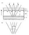
図5は、図4と同じ構成であるが、反射型液晶9により反射された照明光が射出する状態を示している。図5(a)に示すように、今、反射型液晶9のそれぞれの画素9′より、R,G,Bの各色の光束が矢印で示す方向に射出したとすると、画像に使用する光束は、反射型液晶9によりS偏光からP偏光に変換されており、複屈折性を持つ材料8bは、このP偏光に対して、マイクロレンズアレイ8aの持つ屈折率と同じ屈折率の材料として働く。このとき、レンズ素子8は、全体が均質で同じ屈折率を持った材料と同等になるので、射出光束がマイクロレンズアレイ8aの影響を受けて画像が乱れるという事はなくなる。
【0034】
ただ、本例においては、図5(b)に反射光束のみを取り出して示すと、反射光束のR,G,B各々のFナンバーは、RのFナンバーで代表させて同図の実線で角度fとして示すように、3色とも同じ値であるにもかかわらず、主光線の反射する方向がR,G,Bによって異なっているため、同図の点線で角度f′として示すように、個々のFナンバー以上の広がりを持って射出する事になる。ここでは、G,Bの光束は、Rの光束に対して両側に広がるように射出しているので、これを是正し、ひいては投影光学系11のFナンバーを小さく(即ち光学系を明るく)する必要がある。
【0035】
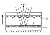
そこで、図6に示すように、G,Bの主光線が矢印で示すようにRと同じ方向を向くように、反射型液晶9の画素9′の内、G,Bが反射するものの反射部に、図示しないDOE(回折格子)を配設してやる事で、投影光学系11をコンパクトにする事ができる。ここでは、画素9′の内、Rが反射するものについては、DOEは無くても差し支えない。
【0036】
また、画素毎にDOEの形状を変えて、反射型液晶9の画面の周辺に向かうほど、より強く光を回折させるようにDOEを配設する事により、コンデンサレンズとしての働きを持たせる事もできる。図7は、このコンデンサレンズの機能を模式的に示す説明図である。同図(a)に示すように、反射型液晶9がコンデンサレンズの機能を持たないときは、矢印で示すように、反射光束が相当の広がりを持って投影光学系11に至るので、それを集光するために、投影光学系11のレンズ径は或程度大きくなる。
【0037】
それに対して、同図(b)に示すように、反射型液晶9がコンデンサレンズの機能を持つときは、矢印で示すように、広がりを抑えた状態で投影光学系11に至るので、それを集光する投影光学系11のレンズ径は小さくて済み、更にコンパクトとなる。
【0038】
図8は、レンズ素子8と反射型液晶9の構成の他の例を模式的に示す図であり、照明光が入射する状態を示している。同図に示すように、レンズ素子8の構成要素として、反射型液晶9の直前に、表面に数十μmオーダーの小さいレンズが多数配列された板状のマイクロレンズアレイ8aが配設されていて、その上面には、透過する偏光の方向によって屈折率が違う、複屈折性を持つ材料8bが施されている。
【0039】
更にその上にはフレネルレンズ8dが配設されていて、その上面には、透過する偏光の方向によって屈折率が違う、別の複屈折性を持つ材料8eが施されている。その上の8cは、保護用のガラス等でできた透明板である。尚、マイクロレンズアレイ8aは、後述するレンチキュラーレンズであっても良い。
【0040】
今、同図の矢印で示す方向より、三原色に色分解された照明光が、レンズ素子8に入射したとすると、この照明光はS偏光であるので、別の複屈折性を持つ材料8eは、このS偏光に対して、フレネルレンズ8dの持つ屈折率と同じ屈折率の材料として働き、これらは均質な材料と同等になる。さらに、複屈折性を持つ材料8bは、斜線で模式的に示すように、このS偏光に対して、マイクロレンズアレイ8aの持つ屈折率とは違った屈折率の材料として働く。そして、これら8a,8bの働きが相俟って、R,G,Bの各所望の色を反射するように配置された反射型液晶9のそれぞれの画素9′上に光束を集光する。こうする事で、光の損失をなくし、画像を明るくする事ができる。
【0041】
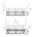
図9は、反射型液晶9により反射された照明光が射出する状態を短辺全長に渡って模式的に示している。そして、同図(a)はフレネルレンズが無い場合であり、図5で説明したものと同じ状態を、全体的に示した形となっている。また、同図(b)はフレネルレンズがある場合である。
【0042】
同図(b)に示すように、今、反射型液晶9のそれぞれの画素9′より、R,G,B(図示せず)の各色の光束が矢印で示す方向に射出したとすると、画像に使用する光束は、反射型液晶9によりS偏光からP偏光に変換されており、複屈折性を持つ材料8bは、このP偏光に対して、マイクロレンズアレイ8aの持つ屈折率と同じ屈折率の材料として働く。このとき、図5の場合と同様にして、射出光束がマイクロレンズアレイ8aの影響を受けて画像が乱れるという事はなくなる。
【0043】
さらに、別の複屈折性を持つ材料8eは、斜線で模式的に示すように、このP偏光に対して、フレネルレンズ8dの持つ屈折率とは違った屈折率の材料として働く。そして、これら8d,8eの働きが相俟って、コンデンサレンズとして機能し、射出光束が広がりを抑えた状態で図示しない投影光学系11に至るので、それを集光する投影光学系11のレンズ径は小さくて済み、コンパクトとなる。
【0044】
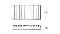
図10は、フレネルレンズ8dの形状を模式的に示す図であり、同図(a)は平面図、(b)は側面縦断面図である。フレネルレンズの表面は、通常、画面の中央部を中心とした輪帯状をしているが、これを本実施形態で使用する場合、ここを通過した反射光束の主光線が、投影光学系11の光軸に必ずしも平行とはならないので、これが画像の質に影響する事がある。こういう場合はむしろ、本発明とは直接関係はないが、図11に平面図(a)及び正面縦断面図(b)で示すように、短辺方向にのみストライプの入ったフレネルレンズを使用する事により、長辺方向の光束の広がりを抑えるにとどめる方が良いときもある。
【0045】
図12は、マイクロレンズアレイ8aの形状を模式的に示す図であり、同図(a)は平面図、(b)は側面縦断面図である。マイクロレンズアレイは、通常、同図に示すように、表面に数十μmオーダーの小さいレンズが多数配列された板状であるが、これは、本実施形態においては、図13に平面図(a)及び側面縦断面図(b)で示すように、ストライプ状の一方向のみの色分離効果を持つレンチキュラーレンズとしても良い。この場合、色分離する方向は、色分解により光束が広がっている方向と一致させる事は言うまでもない。
【0046】
【発明の効果】
以上説明したように、本発明の特に請求項1によれば、効率の良いカラー投影表示装置を提供する事ができる。
【0047】
また、プリズムとする事で、所望の反射特性が得やすくなる。
【0048】
また、請求項2に関して、入射角の角度差を大きくしすぎると、投影光学系のFナンバーを小さくしなければならず、レンズ径が大きくなってしまい、コストアップとなり、逆に入射角の角度差を小さくし過ぎると、色分解の精度が悪くなり、色再現性が悪くなったり、光量損失をおこして画像が暗くなったりするが、この請求項2の条件式範囲に設定する事で、これらの不具合を解決する事ができる。
【0049】
また、請求項3によるならば、照明光を無駄なく使え、明るくする事ができる。また、表示のコントラストを高くする事ができる。
【0050】
また、請求項4によるならば、簡便な構成でフルカラー表示できる。
【0051】
また、請求項5によるならば、回折格子により集光レンズの効果を持たせる事ができ、投影レンズをコンパクトにする事ができる。また、それによりコストダウンを図る事ができる。
【0052】
また、請求項6によるならば、ダイクロイックコートを短波長側或いは長波長側のどちらか一方の反射率の精度を管理するだけで、ダイクロイック偏光ビームスプリッタを比較的簡単に製造する事ができ、コストダウンも図る事ができる。
【0053】
また、請求項7によるならば、白色光源の材料としてメタルハライドランプを使用する場合、赤色の強度が弱い事に鑑み、投影光学系のレンズ周辺で生じるケラレの影響をなくした構成とする事ができる。
【0054】
また、請求項8に関して、入射角の角度差を大きくしすぎると、投影光学系のFナンバーを小さくしなければならず、レンズ径が大きくなってしまい、コストアップとなり、逆に入射角の角度差を小さくし過ぎると、色分解の精度が悪くなり、色再現性が悪くなったり、光量損失をおこして画像が暗くなったりするが、この請求項8の条件式範囲に設定する事で、これらの不具合を解決する事ができる。
【0055】
また、請求項9によるならば、カラー液晶は、入射光と射出光(反射光)で偏光方向を90゜回転する事ができ、光学系を構成しやすく、また安価に製造する事ができるので、コストダウンを図る事ができる。
【図面の簡単な説明】
【図1】本発明の実施形態の全体構成を模式的に示す図。
【図2】ダイクロイック偏光ビームスプリッタの構成を模式的に示す図。
【図3】ガラスプリズムのコーティング面の膜構造の説明図。
【図4】レンズ素子と反射型液晶の構成の一例を模式的に示す図。
【図5】反射型液晶により反射された照明光が射出する状態を示す図。
【図6】反射型液晶にDOEを配設したときの照明光の射出状態を示す図。
【図7】反射型液晶のコンデンサレンズ機能を模式的に示す説明図。
【図8】レンズ素子と反射型液晶の構成の他の例を模式的に示す図。
【図9】照明光が射出する状態をフレネルレンズの有無で比較する図。
【図10】フレネルレンズの形状を模式的に示す図。
【図11】短辺方向にストライプのあるフレネルレンズを模式的に示す図。
【図12】マイクロレンズアレイの形状を模式的に示す図。
【図13】レンチキュラーレンズの形状を模式的に示す図。
【符号の説明】
1 白色光源
2 リフレクター
3 UVIRカットフィルター
4 第1レンズアレイ
5 偏光変換プリズム
6 第2レンズアレイ
7 ダイクロイック偏光ビームスプリッタ
8 レンズ素子
9 反射型液晶
10 偏光板
11 投影光学系[0001]
BACKGROUND OF THE INVENTION
The present invention relates to a single-plate projection color liquid crystal display device that performs color display using a reflective liquid crystal display element.
[0002]
[Prior art]
Conventionally, as described in JP-A-9-5773, JP-A-8-114780, etc., as a single-plate projection type color liquid crystal display device, a white light beam is divided into three primary color light beams, and the light beam Is disclosed in which the same liquid crystal display element is irradiated at different angles to project a light beam modulated by the liquid crystal display element. Since these do not use a mosaic color filter, they do not throw away the light flux that does not pass through the filter, can be projected more efficiently, and are suitable for LCD projectors that require image brightness ing.
[0003]
[Problems to be solved by the invention]
However, since the transmissive liquid crystal is used in any of the above-described configurations, a circuit associated with the liquid crystal pixel is required, so that the aperture efficiency is lowered, and the brightness is lowered accordingly. There is a problem of end. That is, the TFT liquid crystal normally used is provided with a transistor circuit for each pixel, so that when the light beam is transmitted, it is blocked at this portion. The present invention uses, for example, a bright reflective liquid crystal with high aperture efficiency, and decomposes illumination light into light beams of a plurality of different wavelength ranges by a dichroic polarizing beam splitter, and enters the liquid crystal panel at mutually different angles, An object of the present invention is to provide an efficient color projection display device by using a configuration for generating a color image.
[0004]
[Means for Solving the Problems]
In order to achieve the above object, in the present invention, a white light source, and a dividing unit that divides a white light beam from the white light source into light beams of three primary colors of red, green, and blue, and bends the light beam in different directions; A color projection display device comprising: a color display element that forms a color image by modulating light beams incident from different directions by the dividing means; and a projection means that projects a light beam modulated by the color display elements. The color display element is a reflective color display element that receives the light flux from different directions for each wavelength range and emits modulated reflected light, and is modulated and reflected by the reflective color display element. said light beam, saidRi configuration der the dividing means transmitting to the reaching said projectionmeans, said dividing means is a prism having a reflecting surface that forms a different angle from each other Thus, the white light beam is reflected by the reflection surface which differs for each wavelength range, and the incident light beam is collected between the reflective color display element and the dividing means on each pixel of the reflective color display element. By disposing a light-emitting lens element and combining the lens element with a material having birefringence, the incident light beam and the light beam modulated and reflected by the reflective color display element are different from each other. A dichroic polarization beam splitter having three polarization beam splitter surfaces that reflect S-polarized light for each different wavelength region and substantially transmit P-polarized light having a wavelength in the visible light region. It is set as the structure which is .
[0005]
Further, the angle difference between the incident angles at which the light beams divided by the prism are incident on the reflective color display element satisfies the following conditional expression range.
5 ° ≦ θBR ≦ 20 °
5 ° ≦ θGR ≦ 20 ° However,
θBR : Difference between the incident angles of the luminous flux of the blue (B) region and the luminous flux of the red (R) region θGR : Incident of the luminous flux of the green (G) region and the luminous flux of the red (R) region It is the angle difference between each other.
[0006]
The light beam incident on the prism is S-polarized light, and the reflected light modulated and reflected by the reflective color display element is P-polarized light. The wavelength ranges are three wavelength ranges of R, G, and B.
[0008]
In addition, a diffraction grating that reflects the incident light beam in a predetermined direction is disposed in each pixel of the reflective color display element.
[0009]
The wavelength region of the light beam is first separated from the white light beam bythe dichroic polarizing beam splitter has a structure which is red or blue region.
[0010]
Further, the wavelength region of the light beam first separated from the white light beam by the dichroic polarization beam splitter may be a blue region, and the wavelength region of the light beam separated next may be a red region.
[0011]
Further, a lens element for condensing the incident light beam on each pixel of the reflective color display element is disposed between the reflective color display element and the dividing means, and is divided by the dichroic polarizing beam splitter. The angle difference between the incident angles at which the incident light beams enter the lens element satisfies the following conditional expression range.
5 ° ≦ θBR ≦ 20 °
5 ° ≦ θGR ≦ 20 ° However,
θBR : Difference between the incident angles of the luminous flux of the blue (B) region and the luminous flux of the red (R) region θGR : Incident of the luminous flux of the green (G) region and the luminous flux of the red (R) region It is the angle difference between each other.
[0012]
The reflective color display element is a reflective color liquid crystal.
[0013]
DETAILED DESCRIPTION OF THE INVENTION
Hereinafter, embodiments of the present invention will be described with reference to the drawings. FIG. 1 is a diagram schematically showing an overall configuration of an embodiment of the present invention. In the figure, 1 is a white light source, 2 is disposed so as to surround the
[0014]
Here, as the
[0015]
A block dichroic 7 is arranged on the right side of the
[0016]
As shown in the figure, the illumination light (white light beam) in which the direct light from the
[0017]
The white light beam of only S-polarized light incident on the dichroic polarization beam splitter 7 is reflected only by the blue light beam on the surface B shown in FIG. The transmitted light beam reflects only the red light beam on the surface of R, and transmits the others. Further, this transmitted light beam is only a green light beam, and is reflected by the surface of G. The luminous flux divided into these three primary colors passes through the
[0018]
The light beam reflected by the
[0019]
The dichroic polarization beam splitter 7 requires a three-plane splitter of B, R, and G as shown in the figure. As will be described later, the illumination light is color-separated into red (R), green (G), and blue (B) colors, and is effectively guided to the pixels of each color of the
[0020]
The order of reflection of each color in the dichroic polarizing beam splitter 7 is expressed as B → R → G sequentially from the incident side (illumination light side) in the present embodiment, but is not limited thereto. That is, from the incident side, R → G → B, R → B → G, or B → G → R may be used. However, since the metal halide lamp used as the material of the
[0021]
In addition, as will be described later, a coating (dichroic coating) that gives the function of a polarizing beam splitter is applied to each of the R, G, and B surfaces, but the light flux when green (G) S-polarized light is reflected. Since the wavelength band becomes relatively wide, placing the G plane first on the incident side is accompanied by a part of red (R) or blue (B) depending on how the wavelength band to be reflected is set. Is not preferable.
[0022]
As for the arrangement of the
[0023]
FIG. 2 is a diagram schematically showing the configuration of the dichroic polarization beam splitter 7. As shown in the figure, the dichroic polarizing beam splitter 7 is configured by joining four glass prisms (1) to (4). Coating surfaces are formed between (1)-(2), between (2)-(3), and between (3)-(4) of these glass prisms. By making it correspond to each surface, each color beam of S-polarized light is reflected to perform color separation.
[0024]
In the figure, the coating surfaces B, R, and G formed on the glass prism between (1) and (2), between (2) and (3), and between (3) and (4), respectively. The incident angles of the illumination light incident from the left side are represented by θa, θb, and θc, respectively. Also, if the angle at which the reflected lights on the B surface and the R surface intersect is θBR , and the angle at which the reflected lights on the G surface and the R surface intersect is θGR , these are the reflected lights on the B surface and the G surface, respectively. The incident angle to the lens element 8 (and thus the
[0025]
First, the relationship between the angles in the present embodiment is as shown in Table 1 below. When the incident angles θBR and θGR to the
5 ° ≦ θBR ≦ 20 ° 5 ° ≦ θGR ≦ 20 °.
[0026]
[Table 1]
Also, the film structure of the coating surface formed between the glass prisms (1)-(2), (2)-(3), and (3)-(4) is as shown in FIG. . The film configuration shown in Table 1 that effectively reflects S-polarized light and transmits P-polarized light at incident angles θa, θb, and θc on each coating surface is as shown in Table 2 below (S-polarized light Reflection angle and film structure). Here, the refractive index of the glass is set to 1.62. Each coating surface is obtained by laminating a high refractive index material (NH) and a low refractive index material (NL) as shown in FIG. .
[0028]
Here, λ represents a design wavelength, which is approximately 400 to 500 (nm) in the blue (B) region, approximately 500 to 600 (nm) in the green (G) region, and approximately 600 to 600 in the red (R) region. A wavelength of 700 (nm) may be appropriately selected and stacked with a thickness of ¼ wavelength. When each incident angle θa, θb, θc matches one of the values of θ in Table 2, good polarization separation can be obtained. In order to achieve good polarization separation and color separation, usually about 20 layers are laminated.
[0029]
[Table 2]
FIG. 4 is a diagram schematically showing an example of the configuration of the
[0031]
Now, assuming that the illumination light separated into the three primary colors is incident on the
[0032]
Note that liquid crystal is optimal for the material having the birefringence, and the alignment direction of the liquid crystal may be controlled by an alignment process. Furthermore, it is also possible to use a material such as a UV curable liquid crystal that is left solidified by being irradiated with ultraviolet rays when the desired orientation is obtained electrically or by orientation treatment.
[0033]
FIG. 5 shows the same configuration as FIG. 4, but shows a state in which the illumination light reflected by the
[0034]
However, in this example, when only the reflected light beam is extracted and shown in FIG. 5B, the F number of each of R, G, and B of the reflected light beam is represented by the F number of R, and the angle is indicated by the solid line in FIG. As shown as f, although the three colors have the same value, the directions in which the chief rays are reflected differ depending on R, G, and B. Therefore, as indicated by the dotted line in FIG. It will be emitted with a spread more than the F number. Here, since the G and B light beams are emitted so as to spread on both sides of the R light beam, this is corrected, and consequently the F number of the projection
[0035]
Therefore, as shown in FIG. 6, the reflecting portion of the
[0036]
In addition, by changing the shape of the DOE for each pixel and moving the DOE so that it diffracts light more toward the periphery of the screen of the
[0037]
On the other hand, as shown in FIG. 5B, when the
[0038]
FIG. 8 is a diagram schematically showing another example of the configuration of the
[0039]
Further, a
[0040]
Now, from the direction indicated by the arrow in the figure, if the illumination light separated into the three primary colors is incident on the
[0041]
FIG. 9 schematically shows a state where the illumination light reflected by the
[0042]
As shown in FIG. 4B, when light beams of respective colors R, G, B (not shown) are emitted in the directions indicated by arrows from the respective pixels 9 'of the
[0043]
Furthermore, another
[0044]
10A and 10B are diagrams schematically showing the shape of the
[0045]
12A and 12B are diagrams schematically showing the shape of the
[0046]
【The invention's effect】
As described above, according to thefirst aspect of the present invention,it is possible to provide an efficient color projection display device.
[0047]
Also, by using a prism , it is easy to obtain desired reflection characteristics.
[0048]
Further, regarding thesecond aspect , if the angle difference between the incident angles is too large, the F number of the projection optical system must be reduced, the lens diameter is increased, the cost is increased, and conversely the angle of the incident angle. If the difference is made too small, the accuracy of color separation deteriorates and the color reproducibility deteriorates, or the image becomes dark due to loss of light quantity. However, by setting the conditional expression range of this
[0049]
According to thethird aspect , the illumination light can be used without waste and can be brightened. In addition, the display contrast can be increased.
[0050]
According to thefourth aspect , full color display can be performed with a simple configuration.
[0051]
According to thefifth aspect of the present invention , the effect of a condensing lens can be given by the diffraction grating, and the projection lens can be made compact. In addition, the cost can be reduced thereby.
[0052]
According to thesixth aspect of the present invention, the dichroic polarization beam splitter can be manufactured relatively easily only by managing the accuracy of the reflectance of either the short wavelength side or the long wavelength side of the dichroic coat. You can also go down.
[0053]
According to claim7 , when a metal halide lamp is used as the material of the white light source, in view of the weak red intensity, it is possible to eliminate the influence of vignetting that occurs around the lens of the projection optical system. .
[0054]
Further, regarding theeighth aspect of the invention, if the angle difference between the incident angles is too large, the F number of the projection optical system must be reduced, the lens diameter is increased, the cost is increased, and conversely the angle of the incident angle. If the difference is made too small, the accuracy of color separation deteriorates and the color reproducibility deteriorates, or the image becomes dark due to loss of light quantity. However, by setting the conditional expression range of this
[0055]
According to theninth aspect of the present invention, the color liquid crystal can rotate the polarization direction by 90 ° with incident light and outgoing light (reflected light), so that the optical system can be easily constructed and can be manufactured at low cost. Cost can be reduced.
[Brief description of the drawings]
FIG. 1 is a diagram schematically showing an overall configuration of an embodiment of the present invention.
FIG. 2 is a diagram schematically showing a configuration of a dichroic polarizing beam splitter.
FIG. 3 is an explanatory diagram of a film structure of a coating surface of a glass prism.
FIG. 4 is a diagram schematically illustrating an example of a configuration of a lens element and a reflective liquid crystal.
FIG. 5 is a diagram showing a state in which illumination light reflected by a reflective liquid crystal is emitted.
FIG. 6 is a diagram showing an illumination light emission state when a DOE is provided in a reflective liquid crystal.
FIG. 7 is an explanatory view schematically showing a condenser lens function of a reflective liquid crystal.
FIG. 8 is a diagram schematically illustrating another example of a configuration of a lens element and a reflective liquid crystal.
FIG. 9 is a diagram comparing a state in which illumination light is emitted with and without a Fresnel lens.
FIG. 10 is a diagram schematically showing the shape of a Fresnel lens.
FIG. 11 is a diagram schematically showing a Fresnel lens having a stripe in a short side direction.
FIG. 12 is a diagram schematically showing the shape of a microlens array.
FIG. 13 is a diagram schematically showing the shape of a lenticular lens.
[Explanation of symbols]
DESCRIPTION OF
Claims (9)
Translated fromJapanese前記カラー表示素子は、波長範囲毎に異なる方向から前記光束を受け、変調した反射光を出す反射型カラー表示素子であるカラー投影表示装置において、
前記反射型カラー表示素子により変調して反射された前記光束が、前記分割手段を透過して前記投影手段に達する構成であり、前記分割手段は、互いに異なる角度を成す反射面を持つプリズムであり、前記白色光束は、波長範囲毎に異なる前記反射面で反射され、前記反射型カラー表示素子と前記分割手段との間に、前記入射する光束を前記反射型カラー表示素子の各画素に集光するレンズ素子を配設し、該レンズ素子に複屈折性を有する材料を組み合わせる事により、前記入射する光束と前記反射型カラー表示素子により変調して反射された光束とに対して、それぞれ異なるレンズ作用を行わせるようにし、前記分割手段は、異なった波長域毎にS偏光を反射し、可視光域の波長のP偏光をほぼ透過する偏光ビームスプリッタ面を3面持ったダイクロイック偏光ビームスプリッタである事を特徴とするカラー投影表示装置。A white light source, a splitting means for splitting the white light flux from the white light source into light fluxes of the three primary colors red, green, and blue, and bending the light flux in different directions; and a light flux incident from different directions by the splitting means A color projection display apparatus comprising: a color display element that modulates to form a color image; and a projection unit that projects a light beam modulated by the color display element.
The color display element is a reflective color display element that receives the light flux from different directions for each wavelength range and emits modulated reflected light.
The light beam reflected by modulated by the reflection type color display device,Ri configuration der which passes through the dividing means reaches said projectionmeans, said dividing means is a prism having a reflecting surface that forms a different angle from each other The white light beam is reflected by the reflection surface that differs for each wavelength range, and the incident light beam is collected on each pixel of the reflective color display element between the reflective color display element and the dividing means. By disposing a light-emitting lens element and combining the lens element with a material having birefringence, the incident light beam and the light beam modulated and reflected by the reflective color display element are different from each other. The splitting means has three polarization beam splitter surfaces that reflect S-polarized light for each different wavelength range and substantially transmit P-polarized light having a wavelength in the visible light range. Color projection display apparatus, wherein the Rudichroic polarization beam splitter der.
5゜≦θB-R≦20゜
5゜≦θG-R≦20゜
但し、
θB-R:青(B)領域の光束と赤(R)領域の光束のそれぞれの入射角度の互いの角度差
θG-R:緑(G)領域の光束と赤(R)領域の光束のそれぞれの入射角度の互いの角度差
である。2. The color projection display device according to claim1 , wherein an angle difference between incident angles at which the light beams divided by the prism are incident on the reflective color display element satisfies the following conditional expression range. ;
5 ° ≦ θBR ≦ 20 °
5 ° ≦ θGR ≦ 20 ° However,
θBR : Difference between the incident angles of the luminous flux of the blue (B) region and the luminous flux of the red (R) region θGR : Incident of the luminous flux of the green (G) region and the luminous flux of the red (R) region It is the angle difference between each other.
5゜≦θB-R≦20゜
5゜≦θG-R≦20゜
但し、
θB-R:青(B)領域の光束と赤(R)領域の光束のそれぞれの入射角度の互いの角度差
θG-R:緑(G)領域の光束と赤(R)領域の光束のそれぞれの入射角度の互いの角度差
である。A lens element for condensing the incident light beam on each pixel of the reflective color display element is disposed between the reflective color display element and the dividing unit, and the light beam divided by the dichroic polarization beam splitter. There angular difference of mutual incident angle incident on each of the lens elements, following it, thereby satisfying the expression scope of the claims6 or, characterized in claim7 color projection display device;
5 ° ≦ θBR ≦ 20 °
5 ° ≦ θGR ≦ 20 ° However,
θBR : Difference between the incident angles of the luminous flux of the blue (B) region and the luminous flux of the red (R) region θGR : Incident of the luminous flux of the green (G) region and the luminous flux of the red (R) region It is the angle difference between each other.
Priority Applications (2)
| Application Number | Priority Date | Filing Date | Title |
|---|---|---|---|
| JP07902698AJP3747621B2 (en) | 1998-03-26 | 1998-03-26 | Color projection display device |
| US09/276,778US6116739A (en) | 1998-03-26 | 1999-03-25 | Color projection display apparatus |
Applications Claiming Priority (1)
| Application Number | Priority Date | Filing Date | Title |
|---|---|---|---|
| JP07902698AJP3747621B2 (en) | 1998-03-26 | 1998-03-26 | Color projection display device |
Publications (2)
| Publication Number | Publication Date |
|---|---|
| JPH11271677A JPH11271677A (en) | 1999-10-08 |
| JP3747621B2true JP3747621B2 (en) | 2006-02-22 |
Family
ID=13678437
Family Applications (1)
| Application Number | Title | Priority Date | Filing Date |
|---|---|---|---|
| JP07902698AExpired - Fee RelatedJP3747621B2 (en) | 1998-03-26 | 1998-03-26 | Color projection display device |
Country Status (2)
| Country | Link |
|---|---|
| US (1) | US6116739A (en) |
| JP (1) | JP3747621B2 (en) |
Families Citing this family (34)
| Publication number | Priority date | Publication date | Assignee | Title |
|---|---|---|---|---|
| JPH11271744A (en)* | 1998-03-24 | 1999-10-08 | Minolta Co Ltd | Color liquid crystal display device |
| US7450229B2 (en)* | 1999-01-25 | 2008-11-11 | Amnis Corporation | Methods for analyzing inter-cellular phenomena |
| US7057732B2 (en)* | 1999-01-25 | 2006-06-06 | Amnis Corporation | Imaging platform for nanoparticle detection applied to SPR biomolecular interaction analysis |
| US8885913B2 (en) | 1999-01-25 | 2014-11-11 | Amnis Corporation | Detection of circulating tumor cells using imaging flow cytometry |
| US6473176B2 (en)* | 1999-01-25 | 2002-10-29 | Amnis Corporation | Imaging and analyzing parameters of small moving objects such as cells |
| US8131053B2 (en) | 1999-01-25 | 2012-03-06 | Amnis Corporation | Detection of circulating tumor cells using imaging flow cytometry |
| US6975400B2 (en)* | 1999-01-25 | 2005-12-13 | Amnis Corporation | Imaging and analyzing parameters of small moving objects such as cells |
| US6249341B1 (en)* | 1999-01-25 | 2001-06-19 | Amnis Corporation | Imaging and analyzing parameters of small moving objects such as cells |
| US6671044B2 (en) | 1999-01-25 | 2003-12-30 | Amnis Corporation | Imaging and analyzing parameters of small moving objects such as cells in broad flat flow |
| US6707551B2 (en)* | 2000-01-24 | 2004-03-16 | Amnis Corporation | Multipass cavity for illumination and excitation of moving objects |
| US8406498B2 (en) | 1999-01-25 | 2013-03-26 | Amnis Corporation | Blood and cell analysis using an imaging flow cytometer |
| US8005314B2 (en) | 2005-12-09 | 2011-08-23 | Amnis Corporation | Extended depth of field imaging for high speed object analysis |
| US20060257884A1 (en)* | 2004-05-20 | 2006-11-16 | Amnis Corporation | Methods for preparing and analyzing cells having chromosomal abnormalities |
| US6457828B1 (en)* | 1999-04-21 | 2002-10-01 | Minolta Co., Ltd. | Display optical apparatus |
| WO2001053783A1 (en)* | 2000-01-24 | 2001-07-26 | Amnis Corporation | Imaging and analyzing parameters of small moving objects such as cells |
| US6711283B1 (en) | 2000-05-03 | 2004-03-23 | Aperio Technologies, Inc. | Fully automatic rapid microscope slide scanner |
| US6583865B2 (en) | 2000-08-25 | 2003-06-24 | Amnis Corporation | Alternative detector configuration and mode of operation of a time delay integration particle analyzer |
| US6778263B2 (en)* | 2000-08-25 | 2004-08-17 | Amnis Corporation | Methods of calibrating an imaging system using calibration beads |
| US6875973B2 (en)* | 2000-08-25 | 2005-04-05 | Amnis Corporation | Auto focus for a flow imaging system |
| US6934408B2 (en)* | 2000-08-25 | 2005-08-23 | Amnis Corporation | Method and apparatus for reading reporter labeled beads |
| WO2002031583A1 (en) | 2000-10-12 | 2002-04-18 | Amnis Corporation | System and method for high numeric aperture imaging systems |
| US20020135757A1 (en)* | 2001-01-02 | 2002-09-26 | Robotic Vision Systems, Inc. | LCC device inspection module |
| WO2002054139A2 (en)* | 2001-01-02 | 2002-07-11 | Robotic Vision Systems, Inc. | Lcc device inspection module |
| EP2089413A4 (en)* | 2001-02-21 | 2009-10-28 | Amnis Corp | Method and apparatus for labeling and analyzing cellular components |
| EP1389956B1 (en)* | 2001-04-25 | 2012-10-31 | Amnis Corporation | Method and apparatus for correcting crosstalk and spatial resolution for multichannel imaging |
| US7190832B2 (en) | 2001-07-17 | 2007-03-13 | Amnis Corporation | Computational methods for the segmentation of images of objects from background in a flow imaging instrument |
| GB0119176D0 (en)* | 2001-08-06 | 2001-09-26 | Ocuity Ltd | Optical switching apparatus |
| JP2003161810A (en)* | 2001-11-28 | 2003-06-06 | Citizen Electronics Co Ltd | Ultraviolet curing liquid crystalline microlens for contact image sensor |
| EP1725854B1 (en) | 2004-03-16 | 2019-05-08 | Luminex Corporation | Method for imaging and differential analysis of cells |
| EP1800124B1 (en) | 2004-03-16 | 2011-12-21 | Amnis Corporation | Image based quantitation of molecular translocation |
| US8953866B2 (en) | 2004-03-16 | 2015-02-10 | Amnis Corporation | Method for imaging and differential analysis of cells |
| US8804111B2 (en)* | 2007-10-04 | 2014-08-12 | Kla-Tencor Corporation | Multichip CCD camera inspection system |
| US8451524B2 (en) | 2009-09-29 | 2013-05-28 | Amnis Corporation | Modifying the output of a laser to achieve a flat top in the laser's Gaussian beam intensity profile |
| US8817115B1 (en) | 2010-05-05 | 2014-08-26 | Amnis Corporation | Spatial alignment of image data from a multichannel detector using a reference image |
Family Cites Families (9)
| Publication number | Priority date | Publication date | Assignee | Title |
|---|---|---|---|---|
| JP2643755B2 (en)* | 1993-02-26 | 1997-08-20 | 株式会社日立製作所 | Liquid crystal display |
| JP2942129B2 (en)* | 1993-12-24 | 1999-08-30 | シャープ株式会社 | Projection type color liquid crystal display |
| EP0692730A3 (en)* | 1994-07-12 | 1996-03-20 | Dainippon Printing Co Ltd | Liquid crystal display apparatus and liquid crystal projection display apparatus which employ hologram color filter |
| US5852479A (en)* | 1994-09-07 | 1998-12-22 | Sharp Kabushiki Kaisha | Color liquid crystal projector device |
| JP2951858B2 (en)* | 1994-10-17 | 1999-09-20 | シャープ株式会社 | Projection type color liquid crystal display |
| JPH095773A (en)* | 1995-06-23 | 1997-01-10 | Toshiba Corp | Projection type liquid crystal display device |
| EP0763945A3 (en)* | 1995-09-13 | 1998-09-02 | Victor Company Of Japan Limited | Illumination optical system, projection optical system and display apparatus using the same |
| JPH10260375A (en)* | 1997-01-17 | 1998-09-29 | Internatl Business Mach Corp <Ibm> | Liquid crystal projector and its driving method |
| JP3103822B2 (en)* | 1997-07-15 | 2000-10-30 | 日本電気株式会社 | Projection type color liquid crystal display |
- 1998
- 1998-03-26JPJP07902698Apatent/JP3747621B2/ennot_activeExpired - Fee Related
- 1999
- 1999-03-25USUS09/276,778patent/US6116739A/ennot_activeExpired - Fee Related
Also Published As
| Publication number | Publication date |
|---|---|
| JPH11271677A (en) | 1999-10-08 |
| US6116739A (en) | 2000-09-12 |
Similar Documents
| Publication | Publication Date | Title |
|---|---|---|
| JP3747621B2 (en) | Color projection display device | |
| JPH11271744A (en) | Color liquid crystal display device | |
| US5580142A (en) | Image forming apparatus and projector using the same | |
| JP2951858B2 (en) | Projection type color liquid crystal display | |
| JP3780873B2 (en) | Lighting device | |
| JPH06138413A (en) | Plate-type polarization separation device and polarization illumination device using the polarization separation device | |
| JPH11212023A5 (en) | ||
| JP2000019455A (en) | LCD projector | |
| JP2001100311A (en) | projector | |
| JPH068985B2 (en) | Projection display device | |
| JP3437035B2 (en) | Single polarization conversion element and projection display device | |
| JP2000056266A (en) | Optical device | |
| JP3512368B2 (en) | Image projection device | |
| JP4174931B2 (en) | Lighting device and projection display device | |
| JP2000193926A (en) | Light source unit, illumination optical system, and projection display device | |
| JP2004053641A (en) | Polarizing illumination optical system and projection display device using same | |
| JP4946342B2 (en) | Polarization conversion device and projector | |
| JP2000321535A (en) | Parallel light polarization conversion device, illumination device, and liquid crystal projector | |
| JP2000121997A (en) | Projection display device | |
| JP2000066138A (en) | Optical device | |
| JP2768345B2 (en) | LCD projector | |
| JP3669371B2 (en) | Illumination device for image display device | |
| US20050128368A1 (en) | Liquid crystal projector | |
| JP2005284307A (en) | Image display device | |
| JPH11231260A (en) | Image projecting device |
Legal Events
| Date | Code | Title | Description |
|---|---|---|---|
| A711 | Notification of change in applicant | Free format text:JAPANESE INTERMEDIATE CODE: A712 Effective date:20050615 | |
| A521 | Written amendment | Free format text:JAPANESE INTERMEDIATE CODE: A523 Effective date:20050622 | |
| A977 | Report on retrieval | Free format text:JAPANESE INTERMEDIATE CODE: A971007 Effective date:20050804 | |
| A131 | Notification of reasons for refusal | Free format text:JAPANESE INTERMEDIATE CODE: A131 Effective date:20050816 | |
| RD03 | Notification of appointment of power of attorney | Free format text:JAPANESE INTERMEDIATE CODE: A7423 Effective date:20050819 | |
| A521 | Written amendment | Free format text:JAPANESE INTERMEDIATE CODE: A523 Effective date:20051007 | |
| TRDD | Decision of grant or rejection written | ||
| A01 | Written decision to grant a patent or to grant a registration (utility model) | Free format text:JAPANESE INTERMEDIATE CODE: A01 Effective date:20051108 | |
| A61 | First payment of annual fees (during grant procedure) | Free format text:JAPANESE INTERMEDIATE CODE: A61 Effective date:20051121 | |
| R150 | Certificate of patent or registration of utility model | Free format text:JAPANESE INTERMEDIATE CODE: R150 | |
| FPAY | Renewal fee payment (event date is renewal date of database) | Free format text:PAYMENT UNTIL: 20081209 Year of fee payment:3 | |
| FPAY | Renewal fee payment (event date is renewal date of database) | Free format text:PAYMENT UNTIL: 20091209 Year of fee payment:4 | |
| FPAY | Renewal fee payment (event date is renewal date of database) | Free format text:PAYMENT UNTIL: 20101209 Year of fee payment:5 | |
| FPAY | Renewal fee payment (event date is renewal date of database) | Free format text:PAYMENT UNTIL: 20101209 Year of fee payment:5 | |
| FPAY | Renewal fee payment (event date is renewal date of database) | Free format text:PAYMENT UNTIL: 20111209 Year of fee payment:6 | |
| LAPS | Cancellation because of no payment of annual fees |