JP3746717B2 - Bandwidth allocation method in point-multipoint communication system - Google Patents
Bandwidth allocation method in point-multipoint communication systemDownload PDFInfo
- Publication number
- JP3746717B2 JP3746717B2JP2002056461AJP2002056461AJP3746717B2JP 3746717 B2JP3746717 B2JP 3746717B2JP 2002056461 AJP2002056461 AJP 2002056461AJP 2002056461 AJP2002056461 AJP 2002056461AJP 3746717 B2JP3746717 B2JP 3746717B2
- Authority
- JP
- Japan
- Prior art keywords
- slave devices
- bandwidth
- allocation request
- time
- allocation
- Prior art date
- Legal status (The legal status is an assumption and is not a legal conclusion. Google has not performed a legal analysis and makes no representation as to the accuracy of the status listed.)
- Expired - Lifetime
Links
Images


Classifications
- H—ELECTRICITY
- H04—ELECTRIC COMMUNICATION TECHNIQUE
- H04L—TRANSMISSION OF DIGITAL INFORMATION, e.g. TELEGRAPHIC COMMUNICATION
- H04L12/00—Data switching networks
- H04L12/28—Data switching networks characterised by path configuration, e.g. LAN [Local Area Networks] or WAN [Wide Area Networks]
- H04L12/2854—Wide area networks, e.g. public data networks
- H04L12/2856—Access arrangements, e.g. Internet access
- H04L12/2858—Access network architectures
- H04L12/2861—Point-to-multipoint connection from the data network to the subscribers
- H—ELECTRICITY
- H04—ELECTRIC COMMUNICATION TECHNIQUE
- H04J—MULTIPLEX COMMUNICATION
- H04J3/00—Time-division multiplex systems
- H04J3/16—Time-division multiplex systems in which the time allocation to individual channels within a transmission cycle is variable, e.g. to accommodate varying complexity of signals, to vary number of channels transmitted
- H04J3/1694—Allocation of channels in TDM/TDMA networks, e.g. distributed multiplexers
- H—ELECTRICITY
- H04—ELECTRIC COMMUNICATION TECHNIQUE
- H04L—TRANSMISSION OF DIGITAL INFORMATION, e.g. TELEGRAPHIC COMMUNICATION
- H04L12/00—Data switching networks
- H04L12/28—Data switching networks characterised by path configuration, e.g. LAN [Local Area Networks] or WAN [Wide Area Networks]
- H04L12/46—Interconnection of networks
- H04L12/4604—LAN interconnection over a backbone network, e.g. Internet, Frame Relay
- H—ELECTRICITY
- H04—ELECTRIC COMMUNICATION TECHNIQUE
- H04L—TRANSMISSION OF DIGITAL INFORMATION, e.g. TELEGRAPHIC COMMUNICATION
- H04L47/00—Traffic control in data switching networks
- H04L47/10—Flow control; Congestion control
- H04L47/15—Flow control; Congestion control in relation to multipoint traffic
- H—ELECTRICITY
- H04—ELECTRIC COMMUNICATION TECHNIQUE
- H04L—TRANSMISSION OF DIGITAL INFORMATION, e.g. TELEGRAPHIC COMMUNICATION
- H04L47/00—Traffic control in data switching networks
- H04L47/10—Flow control; Congestion control
- H04L47/28—Flow control; Congestion control in relation to timing considerations
- H04L47/283—Flow control; Congestion control in relation to timing considerations in response to processing delays, e.g. caused by jitter or round trip time [RTT]
- H—ELECTRICITY
- H04—ELECTRIC COMMUNICATION TECHNIQUE
- H04L—TRANSMISSION OF DIGITAL INFORMATION, e.g. TELEGRAPHIC COMMUNICATION
- H04L47/00—Traffic control in data switching networks
- H04L47/70—Admission control; Resource allocation
- H—ELECTRICITY
- H04—ELECTRIC COMMUNICATION TECHNIQUE
- H04L—TRANSMISSION OF DIGITAL INFORMATION, e.g. TELEGRAPHIC COMMUNICATION
- H04L47/00—Traffic control in data switching networks
- H04L47/70—Admission control; Resource allocation
- H04L47/78—Architectures of resource allocation
- H04L47/781—Centralised allocation of resources
- H—ELECTRICITY
- H04—ELECTRIC COMMUNICATION TECHNIQUE
- H04L—TRANSMISSION OF DIGITAL INFORMATION, e.g. TELEGRAPHIC COMMUNICATION
- H04L47/00—Traffic control in data switching networks
- H04L47/70—Admission control; Resource allocation
- H04L47/82—Miscellaneous aspects
- H04L47/822—Collecting or measuring resource availability data
- H—ELECTRICITY
- H04—ELECTRIC COMMUNICATION TECHNIQUE
- H04L—TRANSMISSION OF DIGITAL INFORMATION, e.g. TELEGRAPHIC COMMUNICATION
- H04L47/00—Traffic control in data switching networks
- H04L47/70—Admission control; Resource allocation
- H04L47/82—Miscellaneous aspects
- H04L47/826—Involving periods of time
- H—ELECTRICITY
- H04—ELECTRIC COMMUNICATION TECHNIQUE
- H04L—TRANSMISSION OF DIGITAL INFORMATION, e.g. TELEGRAPHIC COMMUNICATION
- H04L47/00—Traffic control in data switching networks
- H04L47/70—Admission control; Resource allocation
- H04L47/82—Miscellaneous aspects
- H04L47/828—Allocation of resources per group of connections, e.g. per group of users
- H—ELECTRICITY
- H04—ELECTRIC COMMUNICATION TECHNIQUE
- H04Q—SELECTING
- H04Q11/00—Selecting arrangements for multiplex systems
- H04Q11/04—Selecting arrangements for multiplex systems for time-division multiplexing
- H04Q11/0428—Integrated services digital network, i.e. systems for transmission of different types of digitised signals, e.g. speech, data, telecentral, television signals
- H04Q11/0478—Provisions for broadband connections
- H—ELECTRICITY
- H04—ELECTRIC COMMUNICATION TECHNIQUE
- H04J—MULTIPLEX COMMUNICATION
- H04J3/00—Time-division multiplex systems
- H04J3/02—Details
- H04J3/06—Synchronising arrangements
- H04J3/0635—Clock or time synchronisation in a network
- H04J3/0682—Clock or time synchronisation in a network by delay compensation, e.g. by compensation of propagation delay or variations thereof, by ranging
- H—ELECTRICITY
- H04—ELECTRIC COMMUNICATION TECHNIQUE
- H04L—TRANSMISSION OF DIGITAL INFORMATION, e.g. TELEGRAPHIC COMMUNICATION
- H04L12/00—Data switching networks
- H04L12/54—Store-and-forward switching systems
- H04L12/56—Packet switching systems
- H04L12/5601—Transfer mode dependent, e.g. ATM
- H04L2012/5603—Access techniques
- H04L2012/5609—Topology
- H04L2012/561—Star, e.g. cross-connect, concentrator, subscriber group equipment, remote electronics
- H—ELECTRICITY
- H04—ELECTRIC COMMUNICATION TECHNIQUE
- H04L—TRANSMISSION OF DIGITAL INFORMATION, e.g. TELEGRAPHIC COMMUNICATION
- H04L12/00—Data switching networks
- H04L12/54—Store-and-forward switching systems
- H04L12/56—Packet switching systems
- H04L12/5601—Transfer mode dependent, e.g. ATM
- H04L2012/5629—Admission control
- H04L2012/5631—Resource management and allocation
- H04L2012/5632—Bandwidth allocation
- H—ELECTRICITY
- H04—ELECTRIC COMMUNICATION TECHNIQUE
- H04L—TRANSMISSION OF DIGITAL INFORMATION, e.g. TELEGRAPHIC COMMUNICATION
- H04L12/00—Data switching networks
- H04L12/54—Store-and-forward switching systems
- H04L12/56—Packet switching systems
- H04L12/5601—Transfer mode dependent, e.g. ATM
- H04L2012/5678—Traffic aspects, e.g. arbitration, load balancing, smoothing, buffer management
- H04L2012/5679—Arbitration or scheduling
Landscapes
- Engineering & Computer Science (AREA)
- Computer Networks & Wireless Communication (AREA)
- Signal Processing (AREA)
- Time-Division Multiplex Systems (AREA)
- Small-Scale Networks (AREA)
- Two-Way Televisions, Distribution Of Moving Picture Or The Like (AREA)
- Telephonic Communication Services (AREA)
Description
Translated fromJapanese【0001】
【発明の属する技術分野】
本発明は、単一の主装置に伝送路を介して複数の従装置が接続され、複数の従装置から主装置への上り伝送帯域を複数の従装置により共用するポイント・マルチポイント通信システムにおける帯域割当方法に関する。
【0002】
【従来の技術】
一般に、LAN,CATV網,衛星通信網,光加入者アクセス網のようなポイント・マルチポイント通信システムにおいては、主装置と複数の従装置が、例えば同軸通信,無線通信,光ファイバ通信等の伝送路を共有して通信を行うように構成されている。
【0003】
例として、通信局内の主装置と加入者宅内の従装置とを光ファイバと光分岐部によって接続したPON伝送システムが挙げられる。図2はPON伝送システムのトポロジを示すブロック図である。単一の主装置1の帯域割当部2に接続された伝送路(光ファイバ)3は、光分岐部4にて複数の光ファイバ5a,5b,5cに分岐され、それぞれが従装置6,7,8に接続される。従装置6,7,8は各々帯域割当部2によって主装置1への上り伝送路帯域が割り当てられる。
【0004】
ここで、この共用される伝送路3を介して、主装置1と各従装置6〜8が円滑な通信をするためには、上り伝送路3の使用を各従装置6〜8へ割り当てるアクセス方式が重要であり、このアクセス方式としては様々な方式が知られている。例えば、従装置は所定の時間内に主装置に対して帯域割当要求を申告し、主装置は、従装置の割当要求量に基づき上り伝送路の帯域割当を算出し、各々の従装置に送信許可を通知する方式がある。主装置は割当要求信号とデータ信号との帯域をそれぞれ割り当てる。
【0005】
このとき,従来技術1として、主装置は、すべての従装置からの割当要求信号帯域を所定の時間内に衝突無く割り当てる方式がある。この方式により、主装置は、すべての従装置の割当要求に基づき各従装置へ帯域を公平に。あるいは設定に基づき。効率的に分配することができる。割当要求信号の帯域は一定周期をもって割り当て、データ信号の帯域はその残余を割り当てる。
【0006】
図3に、従来技術1による割当が行われる過程を示す。一定周期をもって主装置は各々の従装置に上り送信許可信号を送信する。各従装置は当該上り送信許可信号に従い、割当要求受付時間内に到達するよう割当要求信号を主装置に送信する。このとき、上り信号送信許可信号には、各従装置の割当要求信号同士が衝突しないように調整された、従装置毎の送信開始時刻及び送信量を格納しておく。その後、各従装置は、上り信号送信許可信号に従い、データ信号を送信する。
【0007】
すなわち。主装置はK−1周期において受信した、各従装置からの割当要求信号(1,K−1),・・・(P,K−1),‥・に基づき、K周期の割当帯域を算出し、上り送信許可信号(K−1)にて、各従装置に従装置毎の送信開始時刻及び送信量を通知する。このとき、主装置は、全ての従装置からの割当要求量を知ることができるため、最適な次周期の割当を算出することができる。従装置#Pは、上り送信許可信号(K−1)により通知された送信開始時刻。送信量に従い、K周期の割当要求信号(P,K)及びデータ信号(P,K)を送信する。
これらの一連の処理を繰り返すことにより、上り伝送路帯域を動的に割り当てることができる。
【0008】
また、従来技術2として、主装置は、従装置からの割当要求を受けるたびごとに、他の従装置に依らず、当該従装置への割当帯域を算出し、次回の割当要求信号帯域とデータ信号帯域とをそれぞれ未割当帯域に割り当てる方式がある。この方式により、他の従装置からの割当要求を待たずして、該従装置への割当を行うことができる。
【0009】
図4に、従来技術2による割当が行われる過程を示す。固有の周期を持たず、主装置1は各々の従装置6〜8に上り送信許可信号を送信する。従装置6〜8は当該上り送信許可信号に従い、割当要求信号及びデータ信号を主装置1に送信する。主装1置は、従装置6〜8からの割当要求信号を受信するごとに、未割当帯域のうち、最適な帯域を当該従装置の割当要求信号帯域及びデータ信号帯域として割り当てる。
【0010】
すなわち、主装置1は、従装置#Pからの割当要求信号(P,K−1)に基づき、従装置#Pの次回の割当帯域を算出し、上り送信許可信号(P,K−1)により、従装置#Pの次回の送信開始時刻、送信量を通知する。このとき、主装置は、各々の従装置に対し独立に帯域割当を行うため、往復伝搬遅延時間の大きい従装置に依らず、迅速に次回の帯域割当を行うことができ、データ送信までの遅延時間を短くすることができる。従装置#Pは上り送信許可信号(P,K−1)により通知された送信開始時刻、送信量に従い、割当要求信号(P,K)及びデータ信号(P,K)を送信する。この間に、従装置#Pへの割当には依らず、他の各々の従装置への割当がそれぞれ行われる。
これらの一連の処理を繰り返すことにより、上り伝送路帯域を動的に割り当てることができる。
【0011】
【発明が解決しようとする課題】
ところで、上述した従来技術では、伝送帯域を効率的に使用しつつ、かつ従装置内に蓄積されたデータ信号を主装置に送信するまでの遅延時間を短くすることができない。
上記従来方式1においては、帯域を割り当てる周期を短くすることで、遅延時間を短くすることができるが、図5に示すように、すべての従装置からの割当要求信号を一定期間内に受信する必要があるため、最大の往復伝搬遅延時間より割り当てる周期を短くすることはできない。
【0012】
また、上記従来方式2においては、ある従装置へ割り当てる周期を他の従装置の往復伝搬遅延時間に依らずして、当該従装置の往復伝搬遅延時間まで短くすることができるが、他の従装置からの割当要求量の情報を参照せずに、各々の従装置に独立に帯域を割り当てるため、図6に示すように、未割当帯域が離散して非効率な割当しか行い得ない場合や,他の従装置へ長時間にわたる帯域を既に割り当てているために、信号送信までの遅延時間が増大する場合があり、帯域を効率的に使用しつつ、かつ遅延時間を短くすることができない。
【0013】
本発明は、上述した事情に鑑みてなされたもので、単一の主装置から伝送路を介して複数の従装置が接続されたポイント・マルチポイント通信システムにおいて、帯域を効率的に使用しつつ、遅延時間を短<することができる帯域割当方法を提供することを目的とする。
【0014】
【課題を解決するための手段】
本発明の帯域割当方法は、従装置を往復伝搬遅延時間に応じてグルーピングし、従装置グループごとに、送信可能な時間的に前方の未割当帯域に割当要求信号の帯域を衝突なきようまとめて割り当てると共に、送信可能な時間的に前方の未割当帯域をデータ信号の帯域として割り当てることで、帯域を効率的に使用しつつ、かつ、遅れ時間を短くするものである。
【0015】
すなわち、請求項1に記載の発明は、単一の主装置に伝送路を介して複数の従装置が接続され、前記複数の従装置から前記主装置への上り伝送帯域を、前記複数の従装置からの割当要求に基づき、前記主装置が各々の前記複数の従装置にデータ信号帯域と割当要求信号帯域とを割り当てるポイント・マルチポイント通信システムの帯域割当方法において、前記主装置は、前記複数の従装置と前記主装置との間の往復伝搬遅延時間lを量子化した量子化遅延時間lqに基づき前記複数の従装置を分割数N(Nは2以上の整数)でグルーピングし、所定時間内の前記複数の従装置からの割当要求を受信するごとに、各グループ毎にそのグループに属する従装置に割り当てる割当要求信号帯域を、時間的に衝突なきよう近接させ、時間的に可能な限り前方の未割当帯域に割り当て、さらに、前記量子化遅延時間lqと、各々の前記複数の従装置からの割当要求量とに基づき、同一グループの従装置へのデータ信号帯域を、該従装置への前記割当要求信号帯域より時間的に後方で、時間的に可能な限り前方の未割当帯域に割り当てることを特徴とするポイント・マルチポイント通信システムにおける帯域割当方法。である
【0016】
また、請求項2に記載の発明は、請求項1記載のポイント・マルチポイント通信システムにおける帯域割当方法において、前記グルーピングを、
0<l≦a0d ,a0d<l≦a1d,a1d<l≦a2d,・・・asd<l≦lmax
但し、分割係数ai(iは0以上の整数)はai<ai+1なる1以上の整数
lmax=最大往復伝搬遅延時間
d=lmax/N
なるs+2組(sは0≦s≦N−2を満たす任意の整数)に分け、第j(j=0,1,・・・,s+1)グループに属する前記従装置の前記量子化遅延時間lq(j)をaj・d〜lmaxの間のいずれかの値とすることを特徴とする。
【0017】
また、請求項3に記載の発明は、請求項2に記載のポイント・マルチポイント通信システムにおける帯域割当方法において、分割係数をaiをai=2iとすることを特徴とする。
また、請求項4に記載の発明は、請求項1〜請求項3のいずれかの項に記載のポイント・マルチポイント通信システムにおける帯域割当方法において、前記分割数Nを2のべき乗とすることを特徴とする。
【0018】
また、請求項5に記載の発明は、請求項1〜請求項4のいずれかの項に記載のポイント・マルチポイント通信システムにおける帯域割当方法において、前記分割数Nを、前記従装置から前記主装置へのデータ信号到達時間の変化に基づき変更することを特徴とする。
また、請求項6に記載の発明は、請求項1〜請求項5のいずれかの項に記載のポイント・マルチポイント通信システムにおける帯域割当方法において、前記分割数Nが変更されるごとに、前記グルーピングを更新すると共に、前記量子化遅延時間lqを更新することを特徴とする。
【0019】
また、請求項7に記載の発明は、単一の主装置に伝送路を介して複数の従装置が接続され、前記複数の従装置から前記主装置への上り伝送帯域を、前記複数の従装置からの割当要求に基づき、前記主装置が各々の前記複数の従装置にデータ信号帯域と割当要求信号帯域とを割り当てるポイント・マルチポイント通信システムの帯域割当プログラムにおいて、前記複数の従装置と前記主装置との間の往復伝搬遅延時間lを量子化した量子化遅延時間lqの情報に基づき前記複数の従装置を分割数N(Nは2以上の整数)でグルーピングする処理と、所定時間内の前記複数の従装置からの割当要求を受信するごとに、各グループ毎にそのグループに属する従装置に割り当てる割当要求信号帯域を、時間的に衝突なきよう近接させ、時間的に可能な限り前方の未割当帯域に割り当てる処理と、前記量子化遅延時間lqと、各々の前記複数の従装置からの割当要求量とに基づき、同一グループの従装置へのデータ信号帯域を、該従装置への前記割当要求信号帯域より時間的に後方で、時間的に可能な限り前方の未割当帯域に割り当てる処理とを実行するためのプログラムである。
【0020】
【発明の実施の形態】
以下、図面を参照し、この発明の一実施の形態による帯域割当方法を適用したポイント・マルチポイントシ通信システムについて説明する。この実施形態による通信システムのブロック構成は基本的に図2に示す従来の構成と同じであるが、帯域割当部2の機能、動作が異なっている。
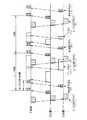
以下、図1を参照し、帯域割当部2の機能、動作を説明する。まず、従来方式1と同じく、基本となる一定周期の割当周期を設定する。基本周期は最大の往復伝搬遅延時間lmaxまで短くする。また、すべての従装置からの割当要求信号を衝突なきよう近接させ、基本周期ごとに受信できるよう割り当てる(図1の符号R0参照)。
【0021】
次に、従装置の往復伝搬遅延時間lに応じて従装置をグルーピングすると共に、従装置の往復伝搬遅延時間lを量子化し、この量子化された同一グループ内の従装置の量子化遅延時間lqを全て等しくする。
グルーピングは、例えば、
lmax=最大往復伝搬遅延時間
d=lmax/N
なるs+2組(sは0≦s≦N−2を満たす任意の整数)に分け、第j(j=0,1,・・・,s+1)グループに属する前記従装置の前記量子化遅延時間lq(j)をaj・d〜lmaxの間のいずれかの値とする。この時、分割係数をaiを、例えば、ai=2iとし、また、分割数Nを、例えば、2のべき乗とする。
【0022】
帯域割当部2では、所定の時間内に受信した従装置からの割当要求信号(符号R0)に基づき、当該従装置への割当要求信号帯域及びデータ信号帯域を割り当てる(符号R1、R2・・・および符号D1、D2・・・)。同一グループの従装置に対しては、割当要求信号帯域を衝突なきよう可能な限り近接させて、可能な限り時間的に前方に割り当てる(符号R1参照)。また、データ信号帯域を可能な限り時間的に前方の空き帯域に割り当てる(符号D1参照)。
【0023】
今周期内の空き帯域への割当ができない場合は、次周期への割当とする。このとき、同一従装置グループ内でのデータ信号帯域の分配、あるいは、今周期内の同一帯域または次周期への割当となった従装置グループ間でのデータ信号帯域の分配方法は、従来技術1における、すべての従装置に対して分配する方式を、同一グループ内の全ての従装置に対して適用する。すなわち、所定の時間内に受信した同一グループ内の全ての従装置からの割当要求(例えば、R1)に基づき、当該グループ内の全ての従装置への次回のデータ信号帯域及び割当要求信号帯域の割当を行う(R2、D2)。あるいは、所定の時間内に受信し、次周期への割当となった全てのグループ内の全ての従装置からの割当要求に基づき、当該全てのグループ内の全ての従装置へのデータ信号帯域及び割当要求信号帯域の割当を行う。
【0024】
図1において、所定の割当要求信号帯域(R0)において受信した割当要求信号を送信した従装置グループに対し、次回の割当要求信号帯域の割当(R1〜Rz)と、データ信号帯域の割当(符号D1〜Dz)を行い、上り送信許可信号(P1〜P3)により通知する。前述したグルーピングによれば、割当要求信号帯域は等間隔で並び、かつ全ての従装置グループが最短の遅延でのみ割当要求信号を送信することができるため、もっとも遅延時間を短くすることができる。
【0025】
また、データ信号帯域は割当要求信号帯域に優先して割り当てるが、基本周期の割当要求信号帯域(R0)及びすでに割当要求信号帯域として割り当てている帯域(R1〜Rz)には割り当てない。さらに、当該基本周期中に割当要求信号帯域を割り当てられない従装置はデータ信号帯域も今周期には割り当てず、次周期への割当とする。また、算出した割当要求信号帯域が、当該帯域内であった場合において、従装置が当該割当要求信号を受信した後に、同周期内のの割当要求信号帯域への割当が時間的に不可能である場合には、次周期の基本割当要求信号帯域に割り当てる。
【0026】
分割数Nを増やすことにより、従装置における上りデータ発生からデータ送信までの時間(遅れ時間)を短くすることが可能であるが、割当要求信号及び上り送信許可信号を送信する回数が増えるため、データ信号帯域の使用効率が低下する。そこで、分割数Nをネットワークの状況に応じて動的に変化させることで、最適な分割数Nを選択する。
【0027】
例えば,TCPのスループットは。ウィンドウサイズ/データ信号の往復伝搬遅延時間で表される。そのため,TCPのスループットは。上り伝送帯域のうちデータ信号帯域として使用できる帯域と、遅れ時間とから決定される。
そこで、データ信号の遅れ時間を監視し、逐次分割数Nを最適な値に変化させることで、いがなるネットワーク状況においても、最善のパフォーマンスを得ることができる。
【0028】
一例を示す、基本周期を0.2ミリ秒としたとき、往復伝搬遅延時間が0.025ミリ秒の低遅延従装置が多数接続され、また0.2ミリ秒の高遅延従装置がごく少数のみ接続されたネットワークを例として示す。多くの低遅延従装置のそれぞれが少量のデータ送信帯域を要求し、高遅延従装置が全く帯域を要求していない場合であれば、分割数Nを8とし、0.025ミリ秒間隔で割当要求帯域を割り当てる。これにより、多数の低遅延従装置は小刻みにデータ信号を送信することができ、全体のパフォーマンスは向上する。一方、低遅延従装置は帯域を要求せず、高遅延従装置が大量の帯域を要求している場合であれば、分割数Nを1とし、基本周期の0.25ミリ秒間隔で帯域割当を行うことで、高遅延従装置は蓄積しているデータを効率よ<送信することができ、やはり全体のパフオーマンスは向上する。
【0029】
【発明の効果】
以上説明したように、本発明の帯域割当方法は、往復伝搬遅延時間lに応じて従装置をグルーピングし、従装置グルーブごとに割当要求信号帯域をまとめて割り当て、まとまった割当要求信号を受信するごとに次回の割当を算出することで、従装置から主装置への上り伝送帯域を効率よく使用しつつ、データ信号送信までの遅れ時間を短くすることが可能となる。
【図面の簡単な説明】
【図1】 本発明の一実施形態によるポイント・マルチポイント通信システムにおける帯域割当方法を説明するためのタイミング図である。
【図2】 ポイント・マルチポイント通信システムの概略構成を示すブロック図である。
【図3】 従来技術1における帯域割当方法を説明するためのタイミング図である。
【図4】 従来技術2における帯域割当方法を説明するためのタイミング図である。
【図5】 従来技術1における非効率な帯域割当を説明するためのタイミング図である。
【図6】 従来技術2における非効率な帯域割当を説明するためのタイミング図である。
【符号の説明】
1…主装置
2…帯域割当部
3…伝送路(光ファイバ)
5a〜5c…光ファイバ
6〜8…従装置[0001]
BACKGROUND OF THE INVENTION
The present invention relates to a point-multipoint communication system in which a plurality of slave devices are connected to a single master device via a transmission line, and an upstream transmission band from the slave devices to the master device is shared by the slave devices. The present invention relates to a bandwidth allocation method.
[0002]
[Prior art]
In general, in a point multipoint communication system such as a LAN, CATV network, satellite communication network, and optical subscriber access network, a master device and a plurality of slave devices transmit, for example, coaxial communication, wireless communication, optical fiber communication, etc. It is configured to communicate by sharing a route.
[0003]
As an example, there is a PON transmission system in which a master device in a communication station and a slave device in a subscriber's house are connected by an optical fiber and an optical branching unit. FIG. 2 is a block diagram showing the topology of the PON transmission system. A transmission path (optical fiber) 3 connected to the
[0004]
Here, in order for the
[0005]
At this time, as the
[0006]
FIG. 3 shows a process in which assignment according to the
[0007]
That is. Based on the allocation request signals (1, K-1),... (P, K-1),. Then, the transmission start time and the transmission amount for each slave device are notified by the uplink transmission permission signal (K−1). At this time, since the master device can know the allocation request amount from all the slave devices, it can calculate the optimal allocation of the next period. The slave device #P is the transmission start time notified by the uplink transmission permission signal (K-1). According to the transmission amount, an allocation request signal (P, K) and a data signal (P, K) having a K cycle are transmitted.
By repeating these series of processes, the uplink transmission path band can be dynamically allocated.
[0008]
Also, as
[0009]
FIG. 4 shows a process in which assignment according to the
[0010]
That is, the
By repeating these series of processes, the uplink transmission path band can be dynamically allocated.
[0011]
[Problems to be solved by the invention]
By the way, in the above-described conventional technology, it is impossible to shorten the delay time until the data signal accumulated in the slave device is transmitted to the master device while efficiently using the transmission band.
In the
[0012]
In the
[0013]
The present invention has been made in view of the above-described circumstances, and efficiently uses a band in a point-multipoint communication system in which a plurality of slave devices are connected from a single master device via a transmission line. Another object of the present invention is to provide a bandwidth allocation method that can shorten the delay time.
[0014]
[Means for Solving the Problems]
In the bandwidth allocation method of the present invention, slave devices are grouped according to the round trip propagation delay time, and for each slave device group, the bandwidth of the allocation request signal is combined with the unallocated bandwidth that is forward in time so that there is no collision. In addition to allocating and allocating the unallocated bandwidth ahead in terms of transmission as a data signal bandwidth, the bandwidth is efficiently used and the delay time is shortened.
[0015]
That is, according to the first aspect of the present invention, a plurality of slave devices are connected to a single master device via a transmission line, and an upstream transmission band from the plurality of slave devices to the master device is increased. In the bandwidth allocation method of the point multipoint communication system in which the master device allocates a data signal band and an allocation request signal bandwidth to each of the plurality of slave devices based on an allocation request from a device. The plurality of slave devices are grouped by a division number N (N is an integer of 2 or more) based on a quantization delay time lq obtained by quantizing the round-trip propagation delay time l between the slave device and the master device, and a predetermined time Each time an allocation request from the plurality of slave devices is received, the allocation request signal bands allocated to the slave devices belonging to that group are made close to each other so as not to collide in time, and as much as possible in time The data signal band to the slave device of the same group is assigned to the slave device based on the quantization delay time lq and the allocation request amount from each of the slave devices. A bandwidth allocation method in a point-multipoint communication system, characterized in that the allocation is performed to an unallocated bandwidth that is temporally backward and temporally possible from the allocation request signal bandwidth. [0016]
The invention according to
0 <l ≦ a0 d, a0 d <l ≦ a1 d, a1 d <l ≦ a2 d,... As d <l ≦ l max
However, the division coefficient ai (i is an integer of 0 or more) is an integer of 1 or more such that ai <ai + 1 lmax = maximum round-trip propagation delay time d = lmax / N
S + 2 sets (where s is an arbitrary integer satisfying 0 ≦ s ≦ N−2) and the quantization delay of the slave device belonging to the jth (j = 0, 1,..., S + 1) group The time lq (j) is set to any value between aj · d and lmax.
[0017]
The invention described in
According to a fourth aspect of the present invention, in the bandwidth allocation method in the point multipoint communication system according to any one of the first to third aspects, the division number N is a power of two. Features.
[0018]
The invention according to claim 5 is the bandwidth allocation method in the point multipoint communication system according to any one of
Further, in the band allocation method in the point multipoint communication system according to any one of
[0019]
According to the seventh aspect of the present invention, a plurality of slave devices are connected to a single master device via a transmission line, and an upstream transmission band from the plurality of slave devices to the master device is increased. In a bandwidth allocation program for a point multipoint communication system in which the master device allocates a data signal band and an allocation request signal bandwidth to each of the plurality of slave devices based on an allocation request from a device, the plurality of slave devices and the plurality of slave devices A process of grouping the plurality of slave devices by a division number N (N is an integer of 2 or more) based on information of a quantization delay time lq obtained by quantizing the round trip propagation delay time l with the master device; Each time a request for allocation from the plurality of slave devices is received, the allocation request signal bands allocated to the slave devices belonging to the group for each group are brought close to each other so as not to collide in time. Based on the process of allocating to the unallocated bandwidth ahead, the quantization delay time lq, and the allocation request amount from each of the plurality of slave devices, the data signal band to the slave devices in the same group is And a process for allocating to an unallocated band that is as far back as possible in time and behind the allocation request signal band.
[0020]
DETAILED DESCRIPTION OF THE INVENTION
Hereinafter, a point-multipoint communication system to which a bandwidth allocation method according to an embodiment of the present invention is applied will be described with reference to the drawings. The block configuration of the communication system according to this embodiment is basically the same as the conventional configuration shown in FIG. 2, but the functions and operations of the
Hereinafter, the function and operation of the
[0021]
Next, the slave devices are grouped according to the round trip propagation delay time l of the slave device, the round trip propagation delay time l of the slave device is quantized, and the quantized delay time lq of the slave device in the quantized same group. Are all equal.
Grouping is, for example,
S + 2 sets (where s is an arbitrary integer satisfying 0 ≦ s ≦ N−2) and the quantization delay of the slave device belonging to the jth (j = 0, 1,..., S + 1) group The time lq (j) is set to any value between aj · d and lmax. At this time, the division coefficient is ai , for example, ai = 2i, and the division number N is, for example, a power of 2.
[0022]
Based on the allocation request signal (symbol R0) from the slave device received within a predetermined time, the
[0023]
If allocation to a free band in the current cycle is not possible, allocation to the next cycle is assumed. At this time, the data signal band distribution within the same slave device group, or the data signal band distribution method between the slave device groups assigned to the same band or the next cycle in the current cycle is the
[0024]
In FIG. 1, the next allocation request signal band allocation (R1 to Rz) and the data signal band allocation (code) to the slave device group that has transmitted the allocation request signal received in the predetermined allocation request signal band (R0). D1 to Dz), and is notified by an uplink transmission permission signal (P1 to P3). According to the above-described grouping, the allocation request signal bands are arranged at equal intervals, and since all the slave device groups can transmit the allocation request signal only with the shortest delay, the delay time can be shortened most.
[0025]
The data signal band is allocated with priority over the allocation request signal band, but is not allocated to the allocation request signal band (R0) of the basic period and the bands (R1 to Rz) already allocated as the allocation request signal band. Further, the slave device that cannot allocate the allocation request signal band during the basic period does not allocate the data signal band in the current period, but allocates it to the next period. In addition, when the calculated allocation request signal band is within the band, after the slave apparatus receives the allocation request signal, allocation to the allocation request signal band within the same period is impossible in terms of time. In some cases, it is assigned to the basic allocation request signal band of the next period.
[0026]
By increasing the number of divisions N, it is possible to shorten the time (delay time) from the generation of uplink data to data transmission in the slave device, but the number of times to transmit the allocation request signal and the uplink transmission permission signal increases. Use efficiency of the data signal band is reduced. Therefore, the optimum number of divisions N is selected by dynamically changing the number of divisions N according to the network conditions.
[0027]
For example, what is the throughput of TCP? Expressed by window size / data signal round trip propagation delay time. Therefore, what is the throughput of TCP? It is determined from the band that can be used as the data signal band in the uplink transmission band and the delay time.
Therefore, by monitoring the delay time of the data signal and changing the sequential division number N to an optimum value, the best performance can be obtained even in a difficult network situation.
[0028]
As an example, when the basic period is 0.2 milliseconds, a large number of low-delay slave devices with a round-trip propagation delay time of 0.025 milliseconds are connected, and a very small number of high-delay slave devices with a 0.2 millisecond number are connected. As an example, a network that is connected only. If each of many low-delay slave devices requires a small amount of data transmission bandwidth and the high-delay slave device does not request any bandwidth, the division number N is set to 8 and assigned at intervals of 0.025 milliseconds. Allocate requested bandwidth. As a result, a large number of low-latency slave devices can transmit data signals in small increments, improving the overall performance. On the other hand, if the low-delay slave device does not request a bandwidth and the high-delay slave device requests a large amount of bandwidth, the division number N is set to 1 and the bandwidth is allocated at intervals of 0.25 milliseconds of the basic period. By performing the above, the high-delay slave device can efficiently transmit the stored data, and the overall performance is also improved.
[0029]
【The invention's effect】
As described above, according to the bandwidth allocation method of the present invention, slave devices are grouped according to the round trip propagation delay time l, the allocation request signal bandwidth is collectively allocated for each slave device group, and a collective allocation request signal is received. By calculating the next allocation for each time, it is possible to shorten the delay time until data signal transmission while efficiently using the upstream transmission band from the slave device to the master device.
[Brief description of the drawings]
FIG. 1 is a timing diagram for explaining a bandwidth allocation method in a point-multipoint communication system according to an embodiment of the present invention.
FIG. 2 is a block diagram showing a schematic configuration of a point-multipoint communication system.
FIG. 3 is a timing diagram for explaining a bandwidth allocation method in the
FIG. 4 is a timing diagram for explaining a bandwidth allocation method in
FIG. 5 is a timing diagram for explaining inefficient bandwidth allocation in the
FIG. 6 is a timing diagram for explaining inefficient bandwidth allocation in the
[Explanation of symbols]
DESCRIPTION OF
5a to 5c:
Claims (7)
Translated fromJapanese前記主装置は、前記複数の従装置と前記主装置との間の往復伝搬遅延時間lを量子化した量子化遅延時間lqに基づき前記複数の従装置を分割数N(Nは2以上の整数)でグルーピングし、
所定時間内の前記複数の従装置からの割当要求を受信するごとに、各グループ毎にそのグループに属する従装置に割り当てる割当要求信号帯域を、時間的に衝突なきよう近接させ、時間的に可能な限り前方の未割当帯域に割り当て、さらに、前記量子化遅延時間lqと、各々の前記複数の従装置からの割当要求量とに基づき、同一グループの従装置へのデータ信号帯域を、該従装置への前記割当要求信号帯域より時間的に後方で、時間的に可能な限り前方の未割当帯域に割り当てることを特徴とするポイント・マルチポイント通信システムにおける帯域割当方法。A plurality of slave devices are connected to a single master device via a transmission path, and the upstream transmission band from the plurality of slave devices to the master device is determined based on an allocation request from the plurality of slave devices. In the bandwidth allocation method of the point multipoint communication system, which allocates a data signal bandwidth and an allocation request signal bandwidth to each of the plurality of slave devices,
The master device divides the plurality of slave devices into a division number N (N is an integer equal to or greater than 2) based on a quantization delay time lq obtained by quantizing the round-trip propagation delay time l between the plurality of slave devices and the master device. )
Each time an allocation request is received from the plurality of slave devices within a predetermined time, the allocation request signal bands allocated to the slave devices belonging to the group for each group are brought close to each other so as not to collide in time, which is possible in time Allocate the data signal band to the slave devices in the same group based on the quantization delay time lq and the allocation request amount from each of the plurality of slave devices. A bandwidth allocating method in a point-multipoint communication system, wherein a bandwidth is allocated to an unallocated bandwidth that is behind the allocation request signal bandwidth to an apparatus and as far forward as possible in time.
0<l≦a0d ,a0d<l≦a1d,a1d<l≦a2d,・・・asd<l≦lmax
但し、分割係数ai(iは0以上の整数)はai<ai+1なる1以上の整数
lmax=最大往復伝搬遅延時間
d=lmax/N
なるs+2組(sは0≦s≦N−2を満たす任意の整数)に分け、
第j(j=0,1,・・・,s+1)グループに属する前記従装置の前記量子化遅延時間lq(j)をaj・d〜lmaxの間のいずれかの値とすることを特徴とする請求項1記載のポイント・マルチポイント通信システムにおける帯域割当方法。The grouping,
0 <l ≦ a0 d, a0 d <l ≦ a1 d, a1 d <l ≦ a2 d,... As d <l ≦ l max
However, the division coefficient ai (i is an integer of 0 or more) is an integer of 1 or more such that ai <ai + 1 lmax = maximum round-trip propagation delay time d = lmax / N
Divided into s + 2 pairs (s is an arbitrary integer satisfying 0 ≦ s ≦ N−2),
The quantization delay time lq (j) of the slave device belonging to the jth (j = 0, 1,..., S + 1) group is set to any value between aj · d and lmax. The bandwidth allocation method in the point multipoint communication system according to claim 1.
前記複数の従装置と前記主装置との間の往復伝搬遅延時間lを量子化した量子化遅延時間lqの情報に基づき前記複数の従装置を分割数N(Nは2以上の整数)でグルーピングする処理と、
所定時間内の前記複数の従装置からの割当要求を受信するごとに、各グループ毎にそのグループに属する従装置に割り当てる割当要求信号帯域を、時間的に衝突なきよう近接させ、時間的に可能な限り前方の未割当帯域に割り当てる処理と、
前記量子化遅延時間lqと、各々の前記複数の従装置からの割当要求量とに基づき、同一グループの従装置へのデータ信号帯域を、該従装置への前記割当要求信号帯域より時間的に後方で、時間的に可能な限り前方の未割当帯域に割り当てる処理と、
を実行するためのプログラム。A plurality of slave devices are connected to a single master device via a transmission path, and the upstream transmission band from the plurality of slave devices to the master device is determined based on an allocation request from the plurality of slave devices. In the band allocation program of the point multipoint communication system that allocates a data signal band and an allocation request signal band to each of the plurality of slave devices,
Based on information of a quantization delay time lq obtained by quantizing a round-trip propagation delay time l between the plurality of slave devices and the master device, the plurality of slave devices are grouped by a division number N (N is an integer of 2 or more). Processing to
Each time an allocation request is received from the plurality of slave devices within a predetermined time, the allocation request signal bands allocated to the slave devices belonging to the group for each group are brought close to each other so as not to collide in time, which is possible in time Allocate to the unallocated bandwidth ahead as much as possible,
Based on the quantization delay time lq and the allocation request amount from each of the plurality of slave devices, the data signal band to the slave devices in the same group is temporally changed from the allocation request signal bandwidth to the slave devices. The process of allocating to the unallocated bandwidth ahead as far as possible in the back,
A program for running.
Priority Applications (5)
| Application Number | Priority Date | Filing Date | Title |
|---|---|---|---|
| JP2002056461AJP3746717B2 (en) | 2002-03-01 | 2002-03-01 | Bandwidth allocation method in point-multipoint communication system |
| CA 2419749CA2419749C (en) | 2002-03-01 | 2003-02-25 | Bandwidth allocation method in point-to-multipoint communication system |
| US10/374,134US7260116B2 (en) | 2002-03-01 | 2003-02-25 | Bandwidth allocation method in point-to-multipoint communication system |
| DE60334041TDE60334041D1 (en) | 2002-03-01 | 2003-02-27 | Method for bandwidth allocation in a point-to-multipoint messaging system |
| EP20030100476EP1341330B1 (en) | 2002-03-01 | 2003-02-27 | Bandwidth allocation method in point-to-multipoint communication system |
Applications Claiming Priority (1)
| Application Number | Priority Date | Filing Date | Title |
|---|---|---|---|
| JP2002056461AJP3746717B2 (en) | 2002-03-01 | 2002-03-01 | Bandwidth allocation method in point-multipoint communication system |
Publications (2)
| Publication Number | Publication Date |
|---|---|
| JP2003258824A JP2003258824A (en) | 2003-09-12 |
| JP3746717B2true JP3746717B2 (en) | 2006-02-15 |
Family
ID=27678599
Family Applications (1)
| Application Number | Title | Priority Date | Filing Date |
|---|---|---|---|
| JP2002056461AExpired - LifetimeJP3746717B2 (en) | 2002-03-01 | 2002-03-01 | Bandwidth allocation method in point-multipoint communication system |
Country Status (5)
| Country | Link |
|---|---|
| US (1) | US7260116B2 (en) |
| EP (1) | EP1341330B1 (en) |
| JP (1) | JP3746717B2 (en) |
| CA (1) | CA2419749C (en) |
| DE (1) | DE60334041D1 (en) |
Families Citing this family (12)
| Publication number | Priority date | Publication date | Assignee | Title |
|---|---|---|---|---|
| KR100651364B1 (en)* | 2002-03-11 | 2006-11-28 | 삼성전자주식회사 | Transmission Bandwidth Allocation Method in Gigabit Ethernet Passive Optical Subscriber Network |
| KR100584383B1 (en)* | 2004-01-20 | 2006-05-26 | 삼성전자주식회사 | Optical fiber termination device for managing link status of optical fiber subscriber devices and Gigabit Ethernet based passive optical subscriber network |
| US8045580B2 (en)* | 2005-04-04 | 2011-10-25 | Nec Corporation | Band control method and communication apparatus |
| JP2007281979A (en)* | 2006-04-10 | 2007-10-25 | Fujitsu Access Ltd | Pon (passive optical network) system |
| US20070248007A1 (en)* | 2006-04-25 | 2007-10-25 | Rajan Govinda N | Broadband access network capacity management |
| JP2008270898A (en)* | 2007-04-16 | 2008-11-06 | Sumitomo Electric Ind Ltd | Optical subscriber line terminal equipment |
| EP2254386B1 (en)* | 2008-03-12 | 2016-08-17 | Nippon Telegraph and Telephone Corporation | Wireless communication method, wireless communication system, base station, and terminal station |
| KR101524873B1 (en)* | 2009-02-17 | 2015-06-02 | 삼성전자주식회사 | Visible light communication method and system |
| JP2010219978A (en)* | 2009-03-18 | 2010-09-30 | Hitachi Ltd | Optical transmission line terminal, passive optical network system, and bandwidth assignment method |
| JP5669613B2 (en)* | 2011-02-18 | 2015-02-12 | 沖電気工業株式会社 | Dynamic bandwidth allocation method, optical communication network, and station side apparatus |
| JP5955627B2 (en)* | 2012-05-02 | 2016-07-20 | シャープ株式会社 | Wireless communication device, wireless communication method, processing device, program |
| US10158457B2 (en)* | 2014-12-02 | 2018-12-18 | Avago Technologies International Sales Pte. Limited | Coordinating frequency division multiplexing transmissions |
Family Cites Families (6)
| Publication number | Priority date | Publication date | Assignee | Title |
|---|---|---|---|---|
| US6334219B1 (en) | 1994-09-26 | 2001-12-25 | Adc Telecommunications Inc. | Channel selection for a hybrid fiber coax network |
| US6272341B1 (en)* | 1995-11-30 | 2001-08-07 | Motient Services Inc. | Network engineering/systems engineering system for mobile satellite communication system |
| IL141104A0 (en)* | 1998-07-27 | 2002-02-10 | Webtv Networks Inc | Remote computer access |
| SE514302C2 (en) | 1998-12-01 | 2001-02-05 | Ericsson Telefon Ab L M | Queue management in packet switched networks |
| EP1172955A2 (en) | 2000-07-14 | 2002-01-16 | Mitsubishi Denki Kabushiki Kaisha | Methods and devices of allocating slots to child stations |
| CA2853156C (en)* | 2000-11-15 | 2015-03-24 | Wi-Lan, Inc. | Improved frame structure for a communication system using adaptive modulation |
- 2002
- 2002-03-01JPJP2002056461Apatent/JP3746717B2/ennot_activeExpired - Lifetime
- 2003
- 2003-02-25USUS10/374,134patent/US7260116B2/enactiveActive
- 2003-02-25CACA 2419749patent/CA2419749C/ennot_activeExpired - Lifetime
- 2003-02-27EPEP20030100476patent/EP1341330B1/ennot_activeExpired - Lifetime
- 2003-02-27DEDE60334041Tpatent/DE60334041D1/ennot_activeExpired - Lifetime
Also Published As
| Publication number | Publication date |
|---|---|
| CA2419749A1 (en) | 2003-09-01 |
| US7260116B2 (en) | 2007-08-21 |
| US20030165118A1 (en) | 2003-09-04 |
| DE60334041D1 (en) | 2010-10-21 |
| EP1341330A2 (en) | 2003-09-03 |
| CA2419749C (en) | 2008-02-05 |
| JP2003258824A (en) | 2003-09-12 |
| EP1341330A3 (en) | 2005-06-22 |
| EP1341330B1 (en) | 2010-09-08 |
Similar Documents
| Publication | Publication Date | Title |
|---|---|---|
| US6980540B1 (en) | Apparatus and method for acquiring an uplink traffic channel, in wireless communications systems | |
| JP3746717B2 (en) | Bandwidth allocation method in point-multipoint communication system | |
| KR102088922B1 (en) | Bandwidth allocating apparatus and method for providing low-latency service in optical network | |
| EP0791255A1 (en) | Entry polling method, device and router for providing contention-based reservation mechanism within minislots | |
| EP1170908A2 (en) | Apportioning bandwidth capacity in communication switching systems | |
| WO2004031918A2 (en) | Method to convey uplink traffic information | |
| JPS6324331B2 (en) | ||
| CN1498472A (en) | Systems and methods for real-time adaptive capacity scheduling | |
| JPWO2009066733A1 (en) | Communication apparatus and bandwidth allocation method | |
| EP1178698A2 (en) | Unused bandwidth allocation in passive optical networks | |
| JPWO2018020559A1 (en) | Optical terminal apparatus and upstream scheduling method for optical network | |
| Andrews et al. | Dynamic bandwidth allocation algorithms for high-speed data wireless networks | |
| CN101883294A (en) | Uplink bandwidth allocation method and device | |
| CN113207048A (en) | Uplink bandwidth allocation method based on neural network prediction in 50G-PON (Passive optical network) | |
| CN110932769A (en) | Multichannel satellite bandwidth dynamic allocation method | |
| CN114585093B (en) | Method, device and equipment for sending service data | |
| JP6450272B2 (en) | Terminal station apparatus and bandwidth allocation method | |
| Clarke et al. | Simultaneous and interleaved polling: an upstream protocol for WDM-PON | |
| KR20040026342A (en) | Media access control scheduling method and EPON system using the method | |
| CN112714498B (en) | Satellite network frequency spectrum defragmentation method, device, system and storage medium | |
| JP2004336578A (en) | Point / multipoint optical transmission system and station side communication device | |
| CN103684866A (en) | Dynamic bandwidth allocation method for Ethernet passive optical network | |
| JP3632646B2 (en) | Communication system, communication terminal, server, and frame transmission control program | |
| JP5815478B2 (en) | Bandwidth allocation method and communication apparatus | |
| KR100986224B1 (en) | Dynamic Bandwidth Allocation Device and Method in Ethernet Passive Optical Subscriber Network |
Legal Events
| Date | Code | Title | Description |
|---|---|---|---|
| A621 | Written request for application examination | Free format text:JAPANESE INTERMEDIATE CODE: A621 Effective date:20040116 | |
| RD04 | Notification of resignation of power of attorney | Free format text:JAPANESE INTERMEDIATE CODE: A7424 Effective date:20040116 | |
| A977 | Report on retrieval | Free format text:JAPANESE INTERMEDIATE CODE: A971007 Effective date:20051111 | |
| TRDD | Decision of grant or rejection written | ||
| A01 | Written decision to grant a patent or to grant a registration (utility model) | Free format text:JAPANESE INTERMEDIATE CODE: A01 Effective date:20051115 | |
| A61 | First payment of annual fees (during grant procedure) | Free format text:JAPANESE INTERMEDIATE CODE: A61 Effective date:20051124 | |
| R151 | Written notification of patent or utility model registration | Ref document number:3746717 Country of ref document:JP Free format text:JAPANESE INTERMEDIATE CODE: R151 | |
| FPAY | Renewal fee payment (event date is renewal date of database) | Free format text:PAYMENT UNTIL: 20091202 Year of fee payment:4 | |
| FPAY | Renewal fee payment (event date is renewal date of database) | Free format text:PAYMENT UNTIL: 20101202 Year of fee payment:5 | |
| FPAY | Renewal fee payment (event date is renewal date of database) | Free format text:PAYMENT UNTIL: 20101202 Year of fee payment:5 | |
| FPAY | Renewal fee payment (event date is renewal date of database) | Free format text:PAYMENT UNTIL: 20111202 Year of fee payment:6 | |
| FPAY | Renewal fee payment (event date is renewal date of database) | Free format text:PAYMENT UNTIL: 20111202 Year of fee payment:6 | |
| FPAY | Renewal fee payment (event date is renewal date of database) | Free format text:PAYMENT UNTIL: 20121202 Year of fee payment:7 | |
| FPAY | Renewal fee payment (event date is renewal date of database) | Free format text:PAYMENT UNTIL: 20121202 Year of fee payment:7 | |
| FPAY | Renewal fee payment (event date is renewal date of database) | Free format text:PAYMENT UNTIL: 20131202 Year of fee payment:8 | |
| S531 | Written request for registration of change of domicile | Free format text:JAPANESE INTERMEDIATE CODE: R313531 | |
| R350 | Written notification of registration of transfer | Free format text:JAPANESE INTERMEDIATE CODE: R350 | |
| EXPY | Cancellation because of completion of term |