JP3746334B2 - Permanent magnet type synchronous motor drive control apparatus and method - Google Patents
Permanent magnet type synchronous motor drive control apparatus and methodDownload PDFInfo
- Publication number
- JP3746334B2 JP3746334B2JP22117096AJP22117096AJP3746334B2JP 3746334 B2JP3746334 B2JP 3746334B2JP 22117096 AJP22117096 AJP 22117096AJP 22117096 AJP22117096 AJP 22117096AJP 3746334 B2JP3746334 B2JP 3746334B2
- Authority
- JP
- Japan
- Prior art keywords
- power converter
- voltage
- battery
- terminal side
- boosting
- Prior art date
- Legal status (The legal status is an assumption and is not a legal conclusion. Google has not performed a legal analysis and makes no representation as to the accuracy of the status listed.)
- Expired - Lifetime
Links
Images


Classifications
- B—PERFORMING OPERATIONS; TRANSPORTING
- B60—VEHICLES IN GENERAL
- B60L—PROPULSION OF ELECTRICALLY-PROPELLED VEHICLES; SUPPLYING ELECTRIC POWER FOR AUXILIARY EQUIPMENT OF ELECTRICALLY-PROPELLED VEHICLES; ELECTRODYNAMIC BRAKE SYSTEMS FOR VEHICLES IN GENERAL; MAGNETIC SUSPENSION OR LEVITATION FOR VEHICLES; MONITORING OPERATING VARIABLES OF ELECTRICALLY-PROPELLED VEHICLES; ELECTRIC SAFETY DEVICES FOR ELECTRICALLY-PROPELLED VEHICLES
- B60L15/00—Methods, circuits, or devices for controlling the traction-motor speed of electrically-propelled vehicles
- B60L15/02—Methods, circuits, or devices for controlling the traction-motor speed of electrically-propelled vehicles characterised by the form of the current used in the control circuit
- B60L15/025—Methods, circuits, or devices for controlling the traction-motor speed of electrically-propelled vehicles characterised by the form of the current used in the control circuit using field orientation; Vector control; Direct Torque Control [DTC]
- B—PERFORMING OPERATIONS; TRANSPORTING
- B60—VEHICLES IN GENERAL
- B60L—PROPULSION OF ELECTRICALLY-PROPELLED VEHICLES; SUPPLYING ELECTRIC POWER FOR AUXILIARY EQUIPMENT OF ELECTRICALLY-PROPELLED VEHICLES; ELECTRODYNAMIC BRAKE SYSTEMS FOR VEHICLES IN GENERAL; MAGNETIC SUSPENSION OR LEVITATION FOR VEHICLES; MONITORING OPERATING VARIABLES OF ELECTRICALLY-PROPELLED VEHICLES; ELECTRIC SAFETY DEVICES FOR ELECTRICALLY-PROPELLED VEHICLES
- B60L15/00—Methods, circuits, or devices for controlling the traction-motor speed of electrically-propelled vehicles
- B60L15/20—Methods, circuits, or devices for controlling the traction-motor speed of electrically-propelled vehicles for control of the vehicle or its driving motor to achieve a desired performance, e.g. speed, torque, programmed variation of speed
- B—PERFORMING OPERATIONS; TRANSPORTING
- B60—VEHICLES IN GENERAL
- B60L—PROPULSION OF ELECTRICALLY-PROPELLED VEHICLES; SUPPLYING ELECTRIC POWER FOR AUXILIARY EQUIPMENT OF ELECTRICALLY-PROPELLED VEHICLES; ELECTRODYNAMIC BRAKE SYSTEMS FOR VEHICLES IN GENERAL; MAGNETIC SUSPENSION OR LEVITATION FOR VEHICLES; MONITORING OPERATING VARIABLES OF ELECTRICALLY-PROPELLED VEHICLES; ELECTRIC SAFETY DEVICES FOR ELECTRICALLY-PROPELLED VEHICLES
- B60L50/00—Electric propulsion with power supplied within the vehicle
- B60L50/50—Electric propulsion with power supplied within the vehicle using propulsion power supplied by batteries or fuel cells
- B60L50/60—Electric propulsion with power supplied within the vehicle using propulsion power supplied by batteries or fuel cells using power supplied by batteries
- H—ELECTRICITY
- H02—GENERATION; CONVERSION OR DISTRIBUTION OF ELECTRIC POWER
- H02P—CONTROL OR REGULATION OF ELECTRIC MOTORS, ELECTRIC GENERATORS OR DYNAMO-ELECTRIC CONVERTERS; CONTROLLING TRANSFORMERS, REACTORS OR CHOKE COILS
- H02P6/00—Arrangements for controlling synchronous motors or other dynamo-electric motors using electronic commutation dependent on the rotor position; Electronic commutators therefor
- H02P6/08—Arrangements for controlling the speed or torque of a single motor
- B—PERFORMING OPERATIONS; TRANSPORTING
- B60—VEHICLES IN GENERAL
- B60L—PROPULSION OF ELECTRICALLY-PROPELLED VEHICLES; SUPPLYING ELECTRIC POWER FOR AUXILIARY EQUIPMENT OF ELECTRICALLY-PROPELLED VEHICLES; ELECTRODYNAMIC BRAKE SYSTEMS FOR VEHICLES IN GENERAL; MAGNETIC SUSPENSION OR LEVITATION FOR VEHICLES; MONITORING OPERATING VARIABLES OF ELECTRICALLY-PROPELLED VEHICLES; ELECTRIC SAFETY DEVICES FOR ELECTRICALLY-PROPELLED VEHICLES
- B60L2200/00—Type of vehicles
- B60L2200/26—Rail vehicles
- B—PERFORMING OPERATIONS; TRANSPORTING
- B60—VEHICLES IN GENERAL
- B60L—PROPULSION OF ELECTRICALLY-PROPELLED VEHICLES; SUPPLYING ELECTRIC POWER FOR AUXILIARY EQUIPMENT OF ELECTRICALLY-PROPELLED VEHICLES; ELECTRODYNAMIC BRAKE SYSTEMS FOR VEHICLES IN GENERAL; MAGNETIC SUSPENSION OR LEVITATION FOR VEHICLES; MONITORING OPERATING VARIABLES OF ELECTRICALLY-PROPELLED VEHICLES; ELECTRIC SAFETY DEVICES FOR ELECTRICALLY-PROPELLED VEHICLES
- B60L2220/00—Electrical machine types; Structures or applications thereof
- B60L2220/10—Electrical machine types
- B60L2220/14—Synchronous machines
- H—ELECTRICITY
- H02—GENERATION; CONVERSION OR DISTRIBUTION OF ELECTRIC POWER
- H02P—CONTROL OR REGULATION OF ELECTRIC MOTORS, ELECTRIC GENERATORS OR DYNAMO-ELECTRIC CONVERTERS; CONTROLLING TRANSFORMERS, REACTORS OR CHOKE COILS
- H02P2201/00—Indexing scheme relating to controlling arrangements characterised by the converter used
- H02P2201/09—Boost converter, i.e. DC-DC step up converter increasing the voltage between the supply and the inverter driving the motor
- Y—GENERAL TAGGING OF NEW TECHNOLOGICAL DEVELOPMENTS; GENERAL TAGGING OF CROSS-SECTIONAL TECHNOLOGIES SPANNING OVER SEVERAL SECTIONS OF THE IPC; TECHNICAL SUBJECTS COVERED BY FORMER USPC CROSS-REFERENCE ART COLLECTIONS [XRACs] AND DIGESTS
- Y02—TECHNOLOGIES OR APPLICATIONS FOR MITIGATION OR ADAPTATION AGAINST CLIMATE CHANGE
- Y02T—CLIMATE CHANGE MITIGATION TECHNOLOGIES RELATED TO TRANSPORTATION
- Y02T10/00—Road transport of goods or passengers
- Y02T10/60—Other road transportation technologies with climate change mitigation effect
- Y02T10/64—Electric machine technologies in electromobility
- Y—GENERAL TAGGING OF NEW TECHNOLOGICAL DEVELOPMENTS; GENERAL TAGGING OF CROSS-SECTIONAL TECHNOLOGIES SPANNING OVER SEVERAL SECTIONS OF THE IPC; TECHNICAL SUBJECTS COVERED BY FORMER USPC CROSS-REFERENCE ART COLLECTIONS [XRACs] AND DIGESTS
- Y02—TECHNOLOGIES OR APPLICATIONS FOR MITIGATION OR ADAPTATION AGAINST CLIMATE CHANGE
- Y02T—CLIMATE CHANGE MITIGATION TECHNOLOGIES RELATED TO TRANSPORTATION
- Y02T10/00—Road transport of goods or passengers
- Y02T10/60—Other road transportation technologies with climate change mitigation effect
- Y02T10/70—Energy storage systems for electromobility, e.g. batteries
- Y—GENERAL TAGGING OF NEW TECHNOLOGICAL DEVELOPMENTS; GENERAL TAGGING OF CROSS-SECTIONAL TECHNOLOGIES SPANNING OVER SEVERAL SECTIONS OF THE IPC; TECHNICAL SUBJECTS COVERED BY FORMER USPC CROSS-REFERENCE ART COLLECTIONS [XRACs] AND DIGESTS
- Y02—TECHNOLOGIES OR APPLICATIONS FOR MITIGATION OR ADAPTATION AGAINST CLIMATE CHANGE
- Y02T—CLIMATE CHANGE MITIGATION TECHNOLOGIES RELATED TO TRANSPORTATION
- Y02T10/00—Road transport of goods or passengers
- Y02T10/60—Other road transportation technologies with climate change mitigation effect
- Y02T10/72—Electric energy management in electromobility
Landscapes
- Engineering & Computer Science (AREA)
- Power Engineering (AREA)
- Transportation (AREA)
- Mechanical Engineering (AREA)
- Life Sciences & Earth Sciences (AREA)
- Sustainable Development (AREA)
- Sustainable Energy (AREA)
- Control Of Ac Motors In General (AREA)
- Electric Propulsion And Braking For Vehicles (AREA)
Description
Translated fromJapanese【0001】
【発明の属する技術分野】
本発明は、永久磁石型同期モータ(以下PMモータと呼ぶ)を制御する駆動制御装置に関する。
【0002】
【従来の技術】
電気自動車の車両走行用モータに対しては、その小形化が強く要請されている。励磁束の発生手段として永久磁石を用いたモータであるPMモータは、単位体積当たり界磁起磁力が大きく従ってその他の種類のモータに比べその小形化が容易であることから、その車両走行用モータとしてPMモータを使用した電気自動車がこれまで各種提案されている。
【0003】
電気自動車の車両走行用モータに対しては、同時に、広い速度範囲(回転数範囲)をカバーできることも要請されている。この要請に応える手法としてこれまで用いられてきているのが、ベクトル制御の一部分である弱め界磁制御である。ここに、ベクトル制御とは、モータ電流IMをトルク電流成分Iq及び界磁電流成分Idに別けて目標制御する方法である。これらの成分のうち、Iqは主磁束即ち永久磁石にて得られる励磁束との鎖交によってトルク(マグネットトルク)を発生させる成分である。また、Idは主磁束を部分的に補助し又は打ち消す励磁束を発生させる成分であり、モータに突極性がある場合にはIdもId・Iqに比例するトルク(リラクタンストルク)を発生させる。モータの速度範囲を拡張しようとすると、即ちより高速回転の領域までモータの動作可能領域を延ばそうとすると、速度起電力ω・E0即ち主磁束E0にて生じモータの回転角速度ωに比例する起電力が原因となって、一般には回転数Nの上昇に応じてモータの端子電圧が上昇し、しばしば電源電圧たるバッテリ電圧VBに相当する値を上回ってしまう。これを防ぐためE0を打ち消す方向の励磁束をIdの制御により発生させ、モータの動作可能領域を通常界磁領域よりも高回転側の弱め界磁領域まで延ばす手法(図6参照)が、上掲の弱め界磁制御であり、これを実行することにより、比較的小出力のモータでも高速回転領域をカバーできる。なお、ベクトル制御には絶対値及びトルク角による態様もあるが、Id,Iqによる態様と等価であるため、以下の説明では区別しない。
【0004】
弱め界磁制御には、このような利点がある反面、効率低下という側面もある。例えば、弱め界磁制御を行っているときのId(以下、弱め界磁電流とも呼ぶ)が多すぎると、トルク発生に寄与しない又は寄与しにくい電流成分であるIdが増えることによって損失が増えてしまう。逆に、弱め界磁電流が少なすぎると弱め界磁本来の目的の達成に支障となる。即ち、モータ出力制御のため電源たるバッテリと駆動対象たるモータの間に設けた電力変換器にストレスが加わる他、必要なIqを出力できなくなる等の支障も生じる。これらを緩和する方法として、本願出願人は、先に、VBに応じて弱め界磁電流の値を変化させる方法を提案している(特開平7−107772号公報参照)。この方法によれば、弱め界磁制御にて発生する損失を、バッテリの電圧あるいは充電状態との関連においては最小化最適化できる。
【0005】
【発明が解決しようとする課題】
しかしながら、弱め界磁制御を行っている限り、弱め界磁電流に起因した損失の発生やこれによるシステム効率の低下を無くすことはできない。本発明の目的の一つは、バッテリ電圧の昇圧という手段を新たに採用することによって、弱め界磁制御を不要とし、ひいてはシステム効率の改善を実現することにある。本発明の目的の一つは、PMモータの目標動作点の位置に応じて昇圧制御を行うことによって、PMモータの動作可能な速度範囲を従来と同程度以上に維持確保することにある。本発明の目的の一つは、バッテリ電圧が低いときには昇圧を行わないようにすることによって、昇圧回路における損失の発生を抑制し、システム効率を更に改善することにある。本発明の目的の一つは、昇圧回路を自律的にバイパスする手段を提供することによって、より自動化されたシステムを実現することにある。本発明の目的の一つは、昇圧回路を強制的にバイパスする手段を提供することによって、回生制動等必要が生じたときに昇圧回路をバイパスできるようにすることにある。本発明の目的の一つは、昇圧回路の利用によって、突入防止回路を廃止できるようにすることにある。
【0006】
【課題を解決するための手段】
このような目的を達成するため、本発明は、バッテリと車両走行用のPMモータの間に接続されVBをIMに変換する電力変換器を用い、速度起電力を有するPMモータを制御する駆動制御装置において、上記電力変換器への供給に先立ちかつ指令に応じ、上記VBを昇圧する昇圧回路と、モータトルクTと回転数Nにて定められる車両運転領域にある上記PMモータの目標動作点の位置及び速度起電力に基づき、目標動作点を実現するに必要な上記電力変換器の直流端子側電圧を算出し、上記電力変換器の直流端子側電圧の算出値が上記VBの検出値及び上記昇圧回路による昇圧後の電圧値を上回っているか否かを判定する判定手段と、判定手段にて上回っていると判定されたときに、上記昇圧回路による昇圧後の電圧値が上記電力変換器の直流端子側電圧の算出値を上回ることとなるよう、上記昇圧回路に昇圧動作を実行させる手段と、を備えることを特徴とする。かかる構成においては、例えば、PMモータの目標動作点が現在のVBの下での出力可能領域よりも高回転側に位置しているときに、この目標動作点が出力可能領域に含まれることになるよう、VBが昇圧される。このように、Idの発生乃至増大を招かない本発明の手法においては、Idに起因した損失の発生やこれによるシステム効率の低下を無くすことが可能になる。また、本発明の手法は、力行可能領域の拡張という点では弱め界磁制御と同じ性格を有しているため、PMモータの動作可能な速度範囲を従来と同程度以上に維持確保できる。
【0007】
本発明は、昇圧回路を常時用いる構成に限定されるものではない。例えば、昇圧回路を介さない導通経路を昇圧回路前後の電圧差に応じバッテリと電力変換器の間に形成/遮断する自律型ゲート素子(例えばダイオード)を設けることにより、昇圧を実行していないときに昇圧回路を自律型ゲート素子にてバイパスすることができる。即ち、VBが低いときに昇圧を行わないようにすることで、昇圧回路における損失の発生を抑制し、システム効率を更に改善することができる。また、このバイパス形成/遮断は自律型ゲート素子により自律的に即ち自動的に実行されるため、そのための制御装置又は手順は不要である。あるいは、昇圧回路を介さない導通経路を指令に応じバッテリと電力変換器の間に形成/遮断する可制御型ゲート素子(例えばサイリスタ)と、目標動作点が回生側に属しているときに可制御型ゲート素子に指令を与え上記導通経路を強制的に形成させる手段とを、設けることにより、回生制動等の必要に応じ昇圧回路をバイパス可能になる。
【0008】
本発明は、昇圧回路を昇圧のみに利用する構成に限定されるものではない。例えば、昇圧回路として、バッテリから放電されるエネルギを蓄積する受動素子(昇圧リアクトル等)と、指令に応じこの受動素子を電力変換器の正側及び負側入力端子に切替接続する能動素子(トランジスタ等)とを有する回路を用いるのであれば、回生時の経路形成にこれらの素子を利用でき、また、突入防止回路、即ち一般に電力変換器直流端子間に設けられている平滑コンデンサの充電により生じる電流を防止する回路を、これらの素子を利用して廃止できる。それには、目標動作点が力行側に属しているときには判定手段における判定の結果及び当該目標動作点の位置に応じて、また当該目標動作点が回生側に属しているとき及び/又は上記永久磁石型同期モータを始動するときには上記受動素子を介した電流経路が上記バッテリと上記電力変換器との間に形成されるよう、上記能動素子に指令するようにすればよい。
【0009】
【発明の実施の形態】
以下、本発明の好適な実施形態に関し図面に基づき説明する。
【0010】
図1に、本発明の一実施形態に係る電気自動車のシステム構成を示す。この実施形態においては三相PMモータ10が車両走行用モータとして用いられている。モータ10の駆動電力は、バッテリ12からインテリジェントパワーモジュール(IPM)14を介し供給される。すなわち、バッテリ12の放電出力は、平滑コンデンサCにて平滑されたうえでIPM14にて直流から三相交流に変換され、その結果得られた電流iu,iv,iwがモータ10の各相巻線に供給される。また、モータ10の出力トルクはコントローラ16によって制御されている。すなわち、コントローラは、車両操縦者によるアクセル、ブレーキ、シフト等の操作に応じ、かつレゾルバ等の回転センサ18にて検出されるモータ10の回転数(またはロータ角度位置)に応じ、スイッチング信号を発生させ、これにより、IPM14を構成するスイッチング素子のスイッチングパターンを制御する。このような制御を実行することによって、モータ10の出力トルクを、車両操縦者のアクセル操作等に応じたトルクとすることができる。この制御にあたっては、モータ10の各巻線に対応して設けられている電流センサ20u,20v,20wによってモータ10の各相電流iu,iv,iwが検出され、コントローラ16にフィードバックされる。
【0011】
また、バッテリ12とIPM14の間には、突入防止回路22、ダイオードDf及びサイリスタDr並びに昇圧回路24が設けられている。これらのうち突入防止回路22は、バッテリ12をIPM14に接続した直後に平滑コンデンサCの充電によって流れる突入電流を抑制乃至防止するための回路であり、イグニッション(IG)の操作に応じオン/オフされる並列接続された2個のスイッチSW1及びSW2、並びにスイッチSW2に直列接続された抵抗Rsから、構成されている。また、昇圧回路24は本発明の特徴の一部をなしており、バッテリ12の端子電圧VBをコントローラ16の制御の下により高い電圧VIに昇圧してIPM14の直流端子間に印加する。ダイオードDfは昇圧回路24の入力端と出力端の間に大きな電位差が発生していないときすなわち昇圧回路24が昇圧動作を実行していないときにこの昇圧回路24をバイパスする手段である。サイリスタDrはコントローラ16から供給される信号にてターンオン/オフし、ダイオードDfによって定まる電流方向とは逆方向の電流経路を発生させる。なお、図中符号25及び26で示されているのはそれぞれVB及びVIを検出するための電圧センサである。また、昇圧回路24の一例構成として、IPM14の直流端子間に順方向直列接続された2個のトランジスタTr1及びTr2、これらのトランジスタに逆並列接続されたダイオードD1及びD2、並びにトランジスタTr1及びTr2の接続点にその一端がまたバッテリ12側に他端が接続された昇圧リアクトルLを備える構成を、示している。
【0012】
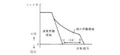
図2に、この実施形態におけるモータ10の速度範囲拡張の原理を示す。この図において領域Aとして表されている領域は図6において通常界磁領域として表された領域に相当している。従来は、モータ回転数Nの上昇に応じて弱め界磁電流Idを増大させることにより、図2中実線で示される特性、すなわち図6中弱め界磁領域として示されている領域まで、モータ10の出力可能領域を拡張していた。これに対し、本実施形態においては、Idの制御によらずに、昇圧回路24の制御によって、モータ10の出力可能領域を拡張している。すなわち、現在の目標動作点(T,N)が、現在のVB又はVIにて実現できる領域よりも高回転側に位置しているときに、本実施形態においては、例えば領域AからBへ、BからCへ、さらにはCからDへ、…というように、モータ10の出力可能領域が広がっていくよう、昇圧回路24により昇圧比を高め、VIを高めている。また、この原理による出力可能領域乃至速度範囲拡張にはIdの制御は関与していないため、従来の弱め界磁制御と異なり、そのような原因によってシステム効率が損われることがない。
【0013】
図3及び図4に、このような原理を実現するためコントローラ16により実行される手順の一例を示す。まず、図3に示されるように、コントローラ16はIGオン直後に突入防止回路22のスイッチSW2をオンさせ、その後しばらく時間が経過した後にスイッチSW1をオンさせる(100)。すなわち、IGオン直後しばらくの間は抵抗Rsを充電抵抗として平滑コンデンサCを充電し、その後平滑コンデンサCが十分充電されたとみなせる時点でSW1をオンさせ抵抗Rsの両端を短絡する。この後、コントローラ16の動作は、モータ10の出力トルク制御のための一連の繰り返し手順に移行する。
【0014】
モータ10の出力トルクを制御するに際しては、コントローラ16は、まず、車両各部から信号を入力する(102)。例えば、アクセル開度、ブレーキ踏力、シフトレバーのポジション、モータ回転数N、モータ電流iu,iv,iw、バッテリ電圧VB、IPM入力電圧VI等を入力する。その後、コントローラ16は、アクセル開度、ブレーキ踏力、シフトポジション、モータ回転数N等の情報に基づきトルク指令T*すなわちモータ10から出力させるべきトルクの目標値を決定する(104)。コントローラ16は、このようにして決定したトルク指令T*に基づき、かつモータ10のシステム効率が最大になるよう、電流指令(Id*,Iq*)を決定する。ここにいう電流指令のうちId*は界磁電流成分Idに関する指令であり、Iq*はトルク電流成分Iqに関する指令である。コントローラ16は、このようにして決定した電流指令(Id*,Iq*)を利用しIPM入力電圧VIの調整を行った後(108)、IPM14その他に信号を出力する(110)。すなわち、電流指令(Id*,Iq*)に応じた電流iu,iv,iwが流れるようIPM14に対しスイッチングパターンを示す信号を出力し、また、トルク指令T*が回生領域(図2中T<0の領域)に属しているときにはサイリスタDrにターンオンする旨の指令を与える。以上ステップ102〜110の動作は、車両操縦者によってIGがオフされるまで繰り返される(112)。IGがオフされると、コントローラ16はスイッチSW1及びSW2をオフさせ(114)、バッテリ12からモータ10への電力の供給を断つ。
【0015】
ステップ108に示されているIPM入力電圧の調整は図4に示されるような手順にて実行される。すなわち、コントローラ16は、例えば次の式
【数1】
Vd=(R+pLd)・Id* −ω・Lq・Iq*
Vq= ω・Ld・Id*+(R+pLq)・Iq*+ω・E0
但し、R:モータ巻線の抵抗
Ld,Lq:モータ巻線のd軸,q軸インダクタンス
ω:モータ電気角速度
E0:主磁束
p:微分演算子
に従い(Vd*,Vq*)を算出する(200)。あるいは、これに代え、次の式
【数2】
Vd=Kp・ΔId+Ki・∫ΔId−ω・Lq・Iq
Vq=Kp・ΔIq+Ki・∫ΔIq+ω・Ld・Id+ωE0
但し、ΔId=Id*−Id
ΔIq=Iq*−Iq
に従い(Vd*,Vq*)を求めてもよい。このようにして得られた(Vd*,Vq*)は、トルク指令T*を実現するのに、あるいは電流指令(Id*,Iq*)を実現するのに必要な電圧を表している。コントローラ16は、さらに、次の式
【数3】
V=k・(Vd2+Vq2)1/2
但し、k:モータ端子電圧をIPM入力電圧に換算するための係数に従い電圧Vを求める。このようにして得られる電圧Vは、モータ10の目標動作点すなわち(T*,N)を実現するのに必要なモータ10の端子電圧をIPM14の直流端子側の値に換算したものである。コントローラ16は、この電圧VがVBを上回っているか否か(204)及びVIを上回っているか否か(206)を判定する。これらの判定条件のうちV>VBの条件が成立していないときには、現在のバッテリ電圧VBをほぼそのまますなわちダイオードDfを介してIPM14にVIとして印加したとき目標動作点(T*,N)を実現できるとみなせるため、コントローラ16は昇圧回路24による昇圧なしで、ステップ110に移行する。また、V>VBの条件が成立しているときは、そのとき昇圧回路24がその動作を開始していないのであればV>VIも必ず成り立つから、コントローラ16の動作はステップ208すなわち昇圧回路24に対する昇圧比の指令動作に移行する。ステップ208においては、コントローラ16は、V<VIを満たすVIが得られるよう、トランジスタTr1及びTr2を制御する動作を開始する。さらに、昇圧回路24による昇圧動作が始まった後でも、昇圧比の不足によってV>VIの条件が成立することがあり、この場合(206)にもステップ208が実行される。
【0016】
以上のような制御手順により、本実施形態においては、図2に示す原理による力行可能領域(特に速度範囲)の確保及びモータシステム効率の改善を実現している。
【0017】
図5に、本発明の第2の実施形態に係る電気自動車のシステム構成を示す。この実施形態においては、突入防止回路22に代えて、バッテリ12をIPM14側と昇圧回路24側とに切替接続するためのスイッチSWが用いられており、かつダイオードDf及びサイリスタDrは廃止されている。また、これに伴い、コントローラ16の動作の手順にも変更が発生している。
【0018】
まず、前述の実施形態においては図3のステップ100においてスイッチSW1及びSW2の時間差オン制御が行われていたが、実施形態においては、ステップ100においてまずスイッチSWが(1)側に倒され、バッテリ12が昇圧回路24に接続される。昇圧回路24には前述のように昇圧リアクトルLが内蔵されている。コントローラ16は、上側のトランジスタTr1をオンさせ、下側のトランジスタTr2をオフさせることにより、昇圧リアクトルL、ダイオードD1を介しバッテリ12がIPM14側に接続された状態を形成し、昇圧リアクトルLを介し平滑コンデンサCを充電することによって第1実施形態における突入防止回路22と同様の機能を達成している。
【0019】
また、コントローラ16は、平滑コンデンサCが十分充電されたとみなせる程度の時間が経過した後にスイッチSWを(3)側に倒し、バッテリ12をIPM14側に接続する。これ以降は、前述の第1実施形態と同様、ステップ102〜110にかかる手順が、車両操縦者がIGをオフするまで繰り返し実行される。ただし、トルク指令T*が回生領域に属しているときには、サイリスタDrをターンオンする制御に代えて、スイッチSWを(1)に倒し、トランジスタTr1をオンさせトランジスタTr2をオフさせる制御が実行される。このような制御により、IGオン直後と同様、昇圧リアクトルLを介した電流経路が形成されるため、バッテリ12へ制動エネルギを回生することが可能になる。また制動エネルギを回生する手段として、スイッチを(3)に倒し、昇圧リアクトルLを介さないで回生することも可能である。また、IGがオフされた後は、コントローラ16はスイッチSWを(2)に倒し、バッテリ12をIPM14からもまた昇圧回路24からも切り離す。
【0020】
このような構成及び手順によっても、前述の第1実施形態と同様、モータ10の出力可能領域を拡張しかつシステム効率を改善することができる。さらに、この実施形態では、突入防止回路その他を廃止することができる。
【0021】
【発明の効果】
本発明によれば、PMモータの目標動作点がその出力可能領域に属していないときに、当該目標動作点の位置に応じVBを昇圧して電力変換器に供給し、これにより、当該目標動作点が属することになるようPMモータの出力可能領域を拡張するようにしたため、PMモータの動作可能な速度範囲を従来と同程度以上に維持確保しながら、弱め界磁制御の廃止ひいてはシステム効率の改善を実現できる。特に、自律型ゲート素子を設けることにより、そのための制御装置又は手順なしで、昇圧回路における損失の発生を抑制し、システム効率を更に改善することができる。また、可制御型ゲート素子やその制御手段を設けることにより、回生制動等の必要に応じ昇圧回路をバイパスできる。そして、昇圧リアクトル等の受動素子を、改正の経路形成や、一般に電力変換器直流端子間に設けられている平滑コンデンサの充電に利用でき、これにより突入防止回路の廃止等回路の簡素化を達成できる。
【0022】
【補遺】
以上の説明では、本発明を「駆動制御装置」に係る発明として表現したが、本発明は例えば「駆動制御方法」「駆動装置」「駆動方法」「電力供給装置」「電力供給方法」等としても表現できる。更に、純粋な電気自動車への応用を想定したが、本発明は電気車やいわゆるハイブリッド車等の他、産業用・民生用の別を問わず各種の用途に適用できる。また、制御対象たる永久磁石型同期モータは、三相交流モータに限定されるものではなく、またリラクタンストルクの利用有無も問わない。
【0023】
更に、モータの出力トルクを回転数検出値に基づきオープンループ制御する構成を前提として説明を行ったが、出力トルクの制御(トルク制御)ではなく回転数の制御(速度制御)を行う構成にも、またオープンループ制御ではなくクローズドループ制御を行う構成にも、更には回転数検出値ではなく回転数推定値に基づき制御を行う構成にも、本発明を適用できる。加えて、モータの動作点を専らトルク回転数空間で表現したが、モータ電圧電流空間等、モータの出力を表現できるのであればその他の種類の空間に準拠してもよい。
【0024】
また、バッテリ電圧が低いときにこれを昇圧しモータの逆起電力を上回るよう調整する例を述べたが、バッテリ電圧が高い領域(の一部)で逆に降圧するようにしてもよい。また、回生時に昇(降)圧を行わない例を示したが、行うようにしてもよい。その場合、IPM内のスイッチング素子等を利用できる。昇(降)圧回路の具体的な構成には、様々な変形が可能である。更に、昇降圧双方の機能を有する回路を用いる場合には、昇圧回路をバイパスするためのスイッチ、ダイオード、サイリスタ等の素子を、廃止することができる。また、前述の第1実施形態ではダイオードとサイリスタの並列回路を用いているが、これに代え双方向サイリスタ等の素子を用いても構わない。昇圧回路の動作に関してはその詳細を省略したが、当該動作は当業者には周知である。
【0025】
なお、上述の実施形態の変形、特にこの欄にて述べた趣旨のものについては、当業者であれば本願の開示に基づき容易に実行できる。
【図面の簡単な説明】
【図1】 本発明の第1実施形態に係る電気自動車のシステム構成を示すブロック図である。
【図2】 本実施形態における出力可能領域拡張及びシステム効率改善の原理を示すトルク回転数空間図である。
【図3】 本実施形態におけるコントローラの動作の流れを示すフローチャートである。
【図4】 本実施形態におけるコントローラの動作の流れを示すフローチャートである。
【図5】 本発明の第2実施形態に係る電気自動車のシステム構成を示すブロック図である。
【図6】 従来の弱め界磁制御を説明するためのトルク回転数空間図である。
【符号の説明】
10 モータ、12 バッテリ、14 IPM、16 コントローラ、18 レゾルバ、24 昇圧回路、25,26 電圧センサ、Df ダイオード、Dr サイリスタ、L 昇圧リアクトル、Tr1,Tr2 昇圧用トランジスタ、SW スイッチ、C 平滑コンデンサ。[0001]
BACKGROUND OF THE INVENTION
The present invention relates to a drive control device that controls a permanent magnet type synchronous motor (hereinafter referred to as PM motor).
[0002]
[Prior art]
There is a strong demand for miniaturization of motors for driving electric vehicles. A PM motor, which is a motor using a permanent magnet as a means for generating an excitation flux, has a large field magnetomotive force per unit volume, and therefore can be easily reduced in size compared to other types of motors. Various electric vehicles using a PM motor have been proposed.
[0003]
At the same time, it is also demanded that a motor for driving a vehicle of an electric vehicle can cover a wide speed range (rotational speed range). The field weakening control, which is a part of vector control, has been used as a method to meet this demand. Here, the vector control is a method of performing target control by dividing the motor current IM into the torque current component Iq and the field current component Id. Among these components, Iq is a component that generates torque (magnet torque) by linkage with the main magnetic flux, that is, the excitation flux obtained by the permanent magnet. Id is a component that generates an excitation flux that partially assists or cancels the main magnetic flux. When the motor has saliency, Id also generates torque (reluctance torque) proportional to Id · Iq. If an attempt is made to extend the speed range of the motor, that is, to extend the operable region of the motor to a region of higher speed rotation, an electromotive force that is generated by the speed electromotive force ω · E0, that is, the main magnetic flux E0 and proportional to the rotational angular velocity ω of the motor As a result, the motor terminal voltage generally increases as the rotational speed N increases, and often exceeds the value corresponding to the battery voltage VB, which is the power supply voltage. In order to prevent this, an excitation bundle in a direction to cancel E0 is generated by controlling Id, and the method of extending the operable region of the motor to the field weakening region higher than the normal field region (see FIG. 6) By executing this field weakening field control, it is possible to cover a high-speed rotation region even with a relatively small output motor. In addition, although there exists an aspect by an absolute value and a torque angle in vector control, since it is equivalent to the aspect by Id and Iq, it does not distinguish in the following description.
[0004]
The field weakening control has such an advantage, but also has an aspect of decreasing efficiency. For example, if there is too much Id during field weakening control (hereinafter also referred to as field weakening current), loss increases due to an increase in Id, which is a current component that does not contribute to or is unlikely to contribute to torque generation. Conversely, if the field weakening current is too small, it will hinder the achievement of the original purpose of the field weakening. That is, in addition to applying stress to the power converter provided between the battery serving as the power source and the motor to be driven for motor output control, problems such as the inability to output necessary Iq also occur. As a method for alleviating these problems, the applicant of the present application has previously proposed a method of changing the value of the field weakening current in accordance with VB (see Japanese Patent Laid-Open No. 7-107772). According to this method, the loss caused by the field weakening control can be minimized and optimized in relation to the battery voltage or the state of charge.
[0005]
[Problems to be solved by the invention]
However, as long as the field weakening control is performed, it is impossible to eliminate the occurrence of loss due to the field weakening current and the decrease in system efficiency due to this. One of the objects of the present invention is to eliminate the need for field-weakening control and to improve the system efficiency by newly adopting a means for boosting the battery voltage. One of the objects of the present invention is to maintain and ensure a speed range in which the PM motor can be operated at a level equal to or higher than that of the prior art by performing boost control according to the position of the target operating point of the PM motor. One of the objects of the present invention is to suppress the occurrence of loss in the booster circuit and further improve the system efficiency by not boosting when the battery voltage is low. One of the objects of the present invention is to realize a more automated system by providing means for autonomously bypassing the booster circuit. One of the objects of the present invention is to provide a means for forcibly bypassing the booster circuit so that the booster circuit can be bypassed when regenerative braking or the like is required. One of the objects of the present invention is to make it possible to eliminate the inrush prevention circuit by using a booster circuit.
[0006]
[Means for Solving the Problems]
In order to achieve such an object, the present invention uses a power converter that is connected between a battery and a PM motor for driving a vehicle and converts VB to IM, and controls driving of the PM motor having speed electromotive force. In the apparatus, prior to supply to the power converter and in response to a command, a booster circuit that boosts the VB, and a target operating pointof the PM motor in a vehicle operating range determined by the motor torque T and the rotational speed NBased on the position and velocity electromotive force, a DC terminal side voltage of the power converter necessary for realizing the target operating point is calculated, and the calculated value of the DC terminal side voltage of the power converter is the detected value of the VB and the above determination meansfor determining whether exceeds the voltage value of the boosted by the boosting circuit, when it is determinedthat the above in the determination unit,the power converter is a voltage value after boosting by the booster circuit So as to be able to exceed the calculated value of the DC terminals side voltage, characterized in that it comprises meansfor executing the step-up operation in the boosting circuit. In such a configuration, for example, when the target operating point of the PM motor is located on the higher rotation side than the output possible region under the current VB, the target operating point is included in the output possible region. VB is boosted so that As described above, in the method of the present invention that does not cause the generation or increase of Id, it is possible to eliminate the occurrence of loss due to Id and the decrease in system efficiency due to this. Further, since the method of the present invention has the same characteristics as field weakening control in terms of expansion of the power running possible region, the speed range in which the PM motor can be operated can be maintained and secured at the same level or higher.
[0007]
The present invention is not limited to the configuration in which the booster circuit is always used. For example, when boosting is not performed by providing an autonomous gate element (for example, a diode) that forms / cuts off a conduction path not passing through the booster circuit between the battery and the power converter according to the voltage difference before and after the booster circuit In addition, the booster circuit can be bypassed by an autonomous gate element. That is, by not performing boosting when VB is low, generation of loss in the boosting circuit can be suppressed, and system efficiency can be further improved. Moreover, since this bypass formation / blocking is autonomously, that is, automatically performed by the autonomous gate element, a control device or procedure for this is not necessary. Alternatively, a controllable gate element (for example, a thyristor) that forms / cuts off a conduction path that does not go through the booster circuit between the battery and the power converter in response to a command, and controllable when the target operating point belongs to the regeneration side By providing means for giving a command to the mold gate element and forcibly forming the conduction path, the booster circuit can be bypassed as necessary for regenerative braking or the like.
[0008]
The present invention is not limited to a configuration in which the booster circuit is used only for boosting. For example, as a booster circuit, a passive element (such as a boosting reactor) that stores energy discharged from a battery, and an active element (transistor) that switches and connects the passive element to the positive and negative input terminals of a power converter according to a command Etc.), these elements can be used to form a path during regeneration, and are generated by charging an inrush prevention circuit, that is, a smoothing capacitor generally provided between the DC terminals of the power converter. Circuits that prevent current can be eliminated using these elements. For that purpose, when the target operating point belongs to the power running side, depending on the result of determination by the determining means and the position of the target operating point, and when the target operating point belongs to the regeneration side and / or the permanent magnet When starting the synchronous motor, the active element may be instructed so that a current path through the passive element is formed between the battery and the power converter.
[0009]
DETAILED DESCRIPTION OF THE INVENTION
Hereinafter, preferred embodiments of the present invention will be described with reference to the drawings.
[0010]
FIG. 1 shows a system configuration of an electric vehicle according to an embodiment of the present invention. In this embodiment, a three-phase PM motor 10 is used as a vehicle driving motor. Driving power of the motor 10 is supplied from the
[0011]
Further, an inrush prevention circuit 22, a diode Df, a thyristor Dr, and a
[0012]
FIG. 2 shows the principle of extending the speed range of the motor 10 in this embodiment. The region represented as region A in this figure corresponds to the region represented as the normal field region in FIG. Conventionally, by increasing the field weakening current Id in accordance with the increase in the motor rotation speed N, the motor 10 reaches the characteristic indicated by the solid line in FIG. 2, that is, the region indicated as the field weakening region in FIG. The possible output area was expanded. On the other hand, in the present embodiment, the output possible region of the motor 10 is expanded by the control of the
[0013]
3 and 4 show an example of a procedure executed by the
[0014]
When controlling the output torque of the motor 10, the
[0015]
The adjustment of the IPM input voltage shown in
Vd = (R + pLd) · Id* −ω · Lq · Iq*
Vq = ω · Ld · Id* + (R + pLq) · Iq* + ω · E0
Where R: resistance of motor winding
Ld, Lq: d-axis and q-axis inductance of motor winding
ω: Motor electrical angular velocity
E0: Main magnetic flux
p: (Vd* , Vq* ) is calculated according to the differential operator (200). Alternatively, instead of the following formula:
Vd = Kp · ΔId + Ki · ∫ΔId−ω · Lq · Iq
Vq = Kp · ΔIq + Ki · ∫ΔIq + ω · Ld · Id + ωE0
However, ΔId = Id* −Id
ΔIq = Iq* −Iq
(Vd* , Vq* ) may be obtained according to the following. The thus obtained (Vd* , Vq* ) represents a voltage necessary for realizing the torque command T* or for realizing the current command (Id* , Iq* ). The
V = k · (Vd2 + Vq2 )1/2
However, k: The voltage V is calculated | required according to the coefficient for converting a motor terminal voltage into an IPM input voltage. The voltage V obtained in this way is obtained by converting the terminal voltage of the motor 10 necessary to realize the target operating point of the motor 10, that is, (T* , N), into a value on the DC terminal side of the
[0016]
According to the control procedure as described above, in this embodiment, the power running possible region (especially the speed range) is secured and the motor system efficiency is improved according to the principle shown in FIG.
[0017]
FIG. 5 shows a system configuration of an electric vehicle according to the second embodiment of the present invention. In this embodiment, instead of the inrush prevention circuit 22, a switch SW for switching the
[0018]
First, in the embodiment described above, the time difference ON control of the switches SW1 and SW2 is performed in
[0019]
In addition, the
[0020]
Also with such a configuration and procedure, the output possible region of the motor 10 can be expanded and the system efficiency can be improved, as in the first embodiment. Furthermore, in this embodiment, the inrush prevention circuit and others can be eliminated.
[0021]
【The invention's effect】
According to the present invention, when the target operating point of the PM motor does not belong to the output possible region, VB is boosted according to the position of the target operating point and supplied to the power converter. Since the output range of the PM motor has been expanded so that the point belongs, the field speed of the PM motor can be maintained at the same level or higher as before, while the field weakening control is abolished and the system efficiency is improved. realizable. In particular, by providing an autonomous gate element, it is possible to suppress the occurrence of loss in the booster circuit and further improve the system efficiency without a control device or procedure therefor. Further, by providing a controllable gate element and its control means, the booster circuit can be bypassed as necessary for regenerative braking or the like. And passive devices such as boosting reactors can be used to form a revised path and to charge a smoothing capacitor that is generally installed between the DC terminals of the power converter, thereby simplifying the circuit by eliminating the inrush prevention circuit. it can.
[0022]
[Addendum]
In the above description, the present invention is expressed as an invention related to a “drive control device”. However, the present invention is described as “drive control method”, “drive device”, “drive method”, “power supply device”, “power supply method”, and the like. Can also be expressed. Furthermore, although the application to a pure electric vehicle was assumed, this invention can be applied to various uses regardless of whether it is for industrial use or consumer use, in addition to an electric vehicle or a so-called hybrid vehicle. Further, the permanent magnet type synchronous motor to be controlled is not limited to a three-phase AC motor, and it does not matter whether or not reluctance torque is used.
[0023]
Further, the description has been made on the assumption that the output torque of the motor is open-loop controlled based on the detected rotation speed value. However, the rotation speed control (speed control) is performed instead of the output torque control (torque control). In addition, the present invention can be applied to a configuration in which closed loop control is performed instead of open loop control, and also in a configuration in which control is performed based on the rotational speed estimation value instead of the rotational speed detection value. In addition, although the operating point of the motor is expressed exclusively in the torque rotation speed space, other types of space may be used as long as the output of the motor can be expressed, such as a motor voltage current space.
[0024]
Further, an example has been described in which when the battery voltage is low, the voltage is boosted and adjusted so as to exceed the counter electromotive force of the motor. However, the voltage may be decreased in a region (part of) where the battery voltage is high. Moreover, although the example which does not perform a raise (down) pressure at the time of regeneration was shown, you may make it carry out. In that case, a switching element in the IPM can be used. Various modifications can be made to the specific configuration of the ascending (falling) pressure circuit. Further, when a circuit having both the step-up and step-down functions is used, elements such as switches, diodes, and thyristors for bypassing the booster circuit can be eliminated. In the first embodiment described above, a parallel circuit of a diode and a thyristor is used, but an element such as a bidirectional thyristor may be used instead. Although details of the operation of the booster circuit have been omitted, such operations are well known to those skilled in the art.
[0025]
Note that modifications of the above-described embodiment, particularly those described in this section, can be easily performed by those skilled in the art based on the disclosure of the present application.
[Brief description of the drawings]
FIG. 1 is a block diagram showing a system configuration of an electric vehicle according to a first embodiment of the present invention.
FIG. 2 is a torque rotation number space diagram showing the principle of expanding the output possible region and improving the system efficiency in the present embodiment.
FIG. 3 is a flowchart showing a flow of operation of the controller in the present embodiment.
FIG. 4 is a flowchart showing a flow of operation of the controller in the present embodiment.
FIG. 5 is a block diagram showing a system configuration of an electric vehicle according to a second embodiment of the present invention.
FIG. 6 is a torque rotation number space diagram for explaining conventional field-weakening control.
[Explanation of symbols]
10 motor, 12 battery, 14 IPM, 16 controller, 18 resolver, 24 booster circuit, 25, 26 voltage sensor, Df diode, Dr thyristor, L boost reactor, Tr1, Tr2 boosting transistor, SW switch, C smoothing capacitor.
Claims (7)
Translated fromJapanese上記電力変換器への供給に先立ちかつ指令に応じ、上記バッテリ電圧を昇圧する昇圧回路と、
モータトルクTと回転数Nにて定められる車両運転領域にある上記永久磁石型同期モータの目標動作点の位置及び速度起電力に基づき、目標動作点を実現するに必要な上記電力変換器の直流端子側電圧を算出し、上記電力変換器の直流端子側電圧の算出値が上記バッテリ電圧の検出値及び上記昇圧回路による昇圧後の電圧値を上回っているか否かを判定する判定手段と、
判定手段にて上回っていると判定されたときに、上記昇圧回路による昇圧後の電圧値が上記電力変換器の直流端子側電圧の算出値を上回ることとなるよう、上記昇圧回路に昇圧動作を実行させる手段と、
を備えることを特徴とする駆動制御装置。In a drive control apparatus for controlling a permanent magnet type synchronous motor having a speed electromotive force, using a power converter connected between a battery and a permanent magnet type synchronous motor for running a vehicle and converting a battery voltage into a motor current,
Prior to supply to the power converter and in response to a command, a booster circuit that boosts the battery voltage;
Based on the position and speed electromotive force of the target operating pointof the permanent magnet type synchronous motor in the vehicle operation range determined by the motor torque T and the rotational speed N, the direct current of the power converter necessary for realizing the target operating point Determining meansfor calculating a terminal side voltageand determiningwhether or nota calculated value of the DC terminal side voltage of the power converterexceeds a detected value of the battery voltage and a voltage value after boosting by the boosting circuit;
Whenit is determined by the determination meansthatthe voltage is boosted by the boosting circuit , theboosting circuit is boosted so that the voltage value after boosting by the boosting circuit exceeds the calculated value of the DC terminal side voltage of the power converter. Means toexecute ,
A drive control device comprising:
上記昇圧回路を介さない導通経路を当該昇圧回路前後の電圧差に応じ上記バッテリと上記電力変換器の間に形成/遮断する自律型ゲート素子を備え、
昇圧を実行していないときに上記昇圧回路が上記自律型ゲート素子により自動的にバイパスされることを特徴とする駆動制御装置。The drive control device according to claim 1,
An autonomous gate element that forms / cuts off a conduction path not through the booster circuit between the battery and the power converter according to a voltage difference before and after the booster circuit;
The drive control device, wherein the booster circuit is automatically bypassed by the autonomous gate element when boosting is not being executed.
上記昇圧回路を介さない導通経路を指令に応じ上記バッテリと上記電力変換器の間に形成/遮断する可制御型ゲート素子と、
上記目標動作点が回生側に属しているときに上記可制御型ゲート素子に指令を与え上記導通経路を強制的に形成させる手段と、
を備えることを特徴とする駆動制御装置。The drive control device according to claim 1,
A controllable gate element that forms / cuts off a conduction path not through the booster circuit between the battery and the power converter in response to a command;
Means for instructing the controllable gate element to forcibly form the conduction path when the target operating point belongs to the regeneration side;
A drive control device comprising:
上記昇圧回路が、上記バッテリから放電されるエネルギを蓄積する受動素子と、指令に応じ上記受動素子を上記電力変換器の正側及び負側入力端子に切替接続する能動素子と、を有し、
上記駆動制御装置が、上記目標動作点が力行側に属しているときには判定手段
における判定の結果及び当該目標動作点の位置に応じて、また当該目標動作点が回生側に属しているとき及び/又は上記永久磁石型同期モータを始動するときには上記受動素子を介した電流経路が上記バッテリと上記電力変換器との間に形成されるよう、上記能動素子に指令する手段を備えることを特徴とする駆動制御装置。The drive control device according to claim 1,
The booster circuit includes a passive element that stores energy discharged from the battery, and an active element that switches and connects the passive element to the positive side and negative side input terminals of the power converter according to a command,
When the target operating point belongs to the power running side, the drive control device depends on the result of determination by the determining means and the position of the target operating point, and when the target operating point belongs to the regeneration side and / or Or a means for instructing the active element so that a current path through the passive element is formed between the battery and the power converter when starting the permanent magnet type synchronous motor. Drive control device.
上記バッテリと上記昇圧回路及び電力変換器との間に、上記電力変換器の直流端子間に設けたコンデンサの充電による突入電流を抑える突入防止回路を設けたことを特徴とする駆動制御装置。The drive control device according to claim 1,
An inrush prevention circuit for suppressing an inrush current due to charging of a capacitor provided between the DC terminals of the power converter is provided between the battery and the booster circuit and the power converter.
モータトルクTと回転数Nにて定められる車両運転領域にある上記永久磁石型同期モータの目標動作点の位置及び速度起電力に基づき上記電力変換器の直流端子側電圧を算出するステップと、
上記電力変換器の直流端子側電圧の算出値が上記バッテリ電圧の検出値を上回っていない場合に、上記昇圧回路による昇圧無しで上記バッテリ電圧を上記電力変換器の直流端子に印加させるステップと、
上記電力変換器の直流端子側電圧の算出値が上記バッテリ電圧の検出値を上回っているけれども上記電力変換器の直流端子側電圧の検出値を上回っていない場合に、上記昇圧回路による昇圧無しで上記バッテリ電圧を上記電力変換器の直流端子に印加させるステップと、
上記電力変換器の直流端子側電圧の算出値が上記バッテリ電圧の検出値及び上記電力変換器の直流端子側電圧の検出値を共に上回っている場合に、上記昇圧回路により昇圧動作を実行させ、上記電力変換器の直流端子側電圧の算出値が上記電力変換器の直流端子側電圧の検出値を上回ることとなるよう、上記昇圧回路に対し昇圧比を指令するステップと、
を有することを特徴とする駆動制御方法。A power converter that is connected between the battery and a permanent magnet type synchronous motor for driving the vehicle and converts the battery voltage into a motor current, and a booster that boosts the battery voltage in response to a command prior to supply to the power converter A drive control method for controlling a permanent magnet type synchronous motor having a speed electromotive force by detecting a battery voltage and a DC terminal side voltage of the power converter using a circuit,
Calculating the DC terminal side voltage of the power converter based on the position and speed electromotive force of the target operating point of the permanent magnet type synchronous motor in the vehicle operation region determined by the motor torque T and the rotational speed N;
When the calculated value of the DC terminal side voltage of the power converter does not exceed the detected value of the battery voltage, applying the battery voltage to the DC terminal of the power converter without boosting by the boosting circuit;
When the calculated value of the DC terminal side voltage of the power converter exceeds the detected value of the battery voltage but does not exceed the detected value of the DC terminal side voltage of the power converter, the boosting circuit does not perform boosting. Applying the battery voltage to a DC terminal of the power converter;
When the calculated value of the DC terminal side voltage of the power converter exceeds both the detected value of the battery voltage and the detected value of the DC terminal side voltage of the power converter, the boosting operation is executed by the boosting circuit, Commanding the boosting ratio to the booster circuit so that the calculated value of the DC terminal side voltage of the power converter exceeds the detected value of the DC terminal side voltage of the power converter;
A drive control method characterized by comprising:
モータトルクTと回転数Nにて定められる車両運転領域にある上記永久磁石型同期モータの目標動作点の位置及び速度起電力に基づき上記電力変換器の直流端子側電圧を算出する手段と、
上記電力変換器の直流端子側電圧の算出値が上記バッテリ電圧の検出値を上回っていない場合に、上記昇圧回路による昇圧無しで上記バッテリ電圧を上記電力変換器の直流端子に印加させる手段と、
上記電力変換器の直流端子側電圧の算出値が上記バッテリ電圧の検出値を上回っているけれども上記電力変換器の直流端子側電圧の検出値を上回っていない場合に、上記昇圧回路による昇圧無しで上記バッテリ電圧を上記電力変換器の直流端子に印加させる手段と、
上記電力変換器の直流端子側電圧の算出値が上記バッテリ電圧の検出値及び上記電力変換器の直流端子側電圧の検出値を共に上回っている場合に、上記昇圧回路により昇圧動作を実行させ、上記電力変換器の直流端子側電圧の算出値が上記電力変換器の直流端子側電圧の検出値を上回ることとなるよう、上記昇圧回路に対し昇圧比を指令する手段と、
を備えることを特徴とする駆動制御装置。A power converter that is connected between the battery and a permanent magnet type synchronous motor for driving the vehicle and converts the battery voltage into a motor current, and a booster that boosts the battery voltage in response to a command prior to supply to the power converter A drive controller for controlling a permanent magnet type synchronous motor having a speed electromotive force by detecting the battery voltage and the DC terminal side voltage of the power converter,
Means for calculating a DC terminal side voltage of the power converter based on a position of a target operating point and a speed electromotive force of the permanent magnet type synchronous motor in a vehicle operation region determined by a motor torque T and a rotational speed N;
Means for applying the battery voltage to the DC terminal of the power converter without boosting by the booster circuit when the calculated value of the DC terminal side voltage of the power converter does not exceed the detected value of the battery voltage;
When the calculated value of the DC terminal side voltage of the power converter exceeds the detected value of the battery voltage but does not exceed the detected value of the DC terminal side voltage of the power converter, the boosting circuit does not perform boosting. Means for applying the battery voltage to a DC terminal of the power converter;
When the calculated value of the DC terminal side voltage of the power converter exceeds both the detected value of the battery voltage and the detected value of the DC terminal side voltage of the power converter, the boosting operation is executed by the boosting circuit, Means for commanding a boost ratio to the booster circuit so that the calculated value of the DC terminal side voltage of the power converter exceeds the detected value of the DC terminal side voltage of the power converter;
A drive control device comprising:
Priority Applications (8)
| Application Number | Priority Date | Filing Date | Title |
|---|---|---|---|
| JP22117096AJP3746334B2 (en) | 1996-08-22 | 1996-08-22 | Permanent magnet type synchronous motor drive control apparatus and method |
| US08/870,391US5883484A (en) | 1996-08-22 | 1997-06-06 | Controller for driving a permanent magnet type synchronous motor |
| DE69740020TDE69740020D1 (en) | 1996-08-22 | 1997-06-13 | Controller for driving a permanent magnetic synchronous motor |
| DE69733866TDE69733866T2 (en) | 1996-08-22 | 1997-06-13 | Controller for driving a permanent magnet synchronous motor |
| EP04023684AEP1504950B1 (en) | 1996-08-22 | 1997-06-13 | Controller for driving a permanent magnet type synchronous motor |
| EP04023689AEP1500549B1 (en) | 1996-08-22 | 1997-06-13 | Controller for driving a permanent magnet type synchronous motor |
| EP97401344AEP0825059B1 (en) | 1996-08-22 | 1997-06-13 | Controller for driving a permanent magnet type synchronous motor |
| DE69740021TDE69740021D1 (en) | 1996-08-22 | 1997-06-13 | Controller for driving a permanent magnetic synchronous motor |
Applications Claiming Priority (1)
| Application Number | Priority Date | Filing Date | Title |
|---|---|---|---|
| JP22117096AJP3746334B2 (en) | 1996-08-22 | 1996-08-22 | Permanent magnet type synchronous motor drive control apparatus and method |
Related Child Applications (2)
| Application Number | Title | Priority Date | Filing Date |
|---|---|---|---|
| JP2002234571ADivisionJP3482965B2 (en) | 2002-08-12 | 2002-08-12 | Drive control device for permanent magnet type synchronous motor |
| JP2003358558ADivisionJP3750681B2 (en) | 2003-10-17 | 2003-10-17 | Permanent magnet type synchronous motor drive control apparatus and method |
Publications (2)
| Publication Number | Publication Date |
|---|---|
| JPH1066383A JPH1066383A (en) | 1998-03-06 |
| JP3746334B2true JP3746334B2 (en) | 2006-02-15 |
Family
ID=16762579
Family Applications (1)
| Application Number | Title | Priority Date | Filing Date |
|---|---|---|---|
| JP22117096AExpired - LifetimeJP3746334B2 (en) | 1996-08-22 | 1996-08-22 | Permanent magnet type synchronous motor drive control apparatus and method |
Country Status (4)
| Country | Link |
|---|---|
| US (1) | US5883484A (en) |
| EP (3) | EP0825059B1 (en) |
| JP (1) | JP3746334B2 (en) |
| DE (3) | DE69733866T2 (en) |
Cited By (4)
| Publication number | Priority date | Publication date | Assignee | Title |
|---|---|---|---|---|
| DE112008000422T5 (en) | 2007-02-16 | 2009-12-03 | Komatsu Ltd. | Voltage control device and voltage control method |
| DE112008002482T5 (en) | 2008-01-31 | 2010-07-08 | Aisin AW Co., Ltd., Anjo-shi | Control device for a rotating electrical machine |
| US8281886B2 (en) | 2007-11-01 | 2012-10-09 | Aisin Aw Co., Ltd. | Electric motor control device, drive device and hybrid drive device |
| US8928263B2 (en) | 2012-06-26 | 2015-01-06 | Honda Motor Co., Ltd. | Control apparatus in motor drive system and method of controlling motor drive system |
Families Citing this family (68)
| Publication number | Priority date | Publication date | Assignee | Title |
|---|---|---|---|---|
| JP3734236B2 (en)* | 1997-12-10 | 2006-01-11 | サンデン株式会社 | Electric vehicle air conditioner power supply input circuit |
| US6554088B2 (en) | 1998-09-14 | 2003-04-29 | Paice Corporation | Hybrid vehicles |
| JP2000333422A (en)* | 1999-05-20 | 2000-11-30 | Techno Takatsuki Co Ltd | Induction synchronous motor |
| EP1202427B1 (en)* | 2000-10-27 | 2013-08-28 | Invensys Systems, Inc. | Load voltage controller for a field device and related control method |
| EP1414145B1 (en)* | 2001-08-02 | 2019-12-25 | Toyota Jidosha Kabushiki Kaisha | Motor drive control apparatus |
| US6917179B2 (en) | 2001-10-25 | 2005-07-12 | Toyota Jidosha Kabushiki Kaisha | Load driver and control method for safely driving DC load and computer-readable recording medium with program recorded thereon for allowing computer to execute the control |
| TW539934B (en)* | 2001-12-06 | 2003-07-01 | Delta Electronics Inc | Inrush current suppression circuit |
| JP3632657B2 (en) | 2001-12-20 | 2005-03-23 | トヨタ自動車株式会社 | Voltage converter |
| US7847499B2 (en) | 2001-12-26 | 2010-12-07 | Toyota Jidosha Kabushiki Kaisha | Electric load apparatus, electric load controlling method and computer readable recording medium recording program for causing computer to execute control of electric load |
| KR100541724B1 (en) | 2002-11-08 | 2006-01-11 | 삼성전자주식회사 | Motor power supply and motor power supply method |
| US6963182B2 (en)* | 2002-11-29 | 2005-11-08 | Toyoda Koki Kabushiki Kaisha | Motor control device and motor control method |
| US7102305B2 (en)* | 2003-05-22 | 2006-09-05 | Toyoda Koki Kabushiki Kaisha | Apparatus and method for controlling motor |
| US7075194B2 (en)* | 2003-07-31 | 2006-07-11 | The Titan Corporation | Electronically reconfigurable battery |
| JP4220851B2 (en)* | 2003-07-31 | 2009-02-04 | トヨタ自動車株式会社 | VOLTAGE CONVERTER AND COMPUTER-READABLE RECORDING MEDIUM RECORDING PROGRAM FOR CAUSING COMPUTER TO EXECUTE VOLTAGE CONVERSION |
| JP4280573B2 (en) | 2003-07-31 | 2009-06-17 | トヨタ自動車株式会社 | Load drive device |
| JP4223880B2 (en)* | 2003-07-31 | 2009-02-12 | トヨタ自動車株式会社 | Motor drive device |
| US7259477B2 (en)* | 2003-08-15 | 2007-08-21 | American Power Conversion Corporation | Uninterruptible power supply |
| JP2005219133A (en)* | 2004-02-03 | 2005-08-18 | Fanuc Ltd | Servo motor control device for robot, and robot |
| JP2005255085A (en)* | 2004-03-15 | 2005-09-22 | Sanyo Electric Co Ltd | Air-conditioner for vehicle |
| DE602005020085D1 (en)* | 2004-05-17 | 2010-05-06 | Sanyo Electric Co | Inverter with a detection of fusion of the relay contacts |
| JP4043481B2 (en)* | 2004-06-25 | 2008-02-06 | 三洋電機株式会社 | Inverter device |
| EP1779503A2 (en)* | 2004-07-05 | 2007-05-02 | Moteurs Leroy-Somer | Rectifier and system for controlling the speed of an electric motor |
| JP4665569B2 (en)* | 2004-11-30 | 2011-04-06 | トヨタ自動車株式会社 | VOLTAGE CONVERTER AND COMPUTER-READABLE RECORDING MEDIUM RECORDING PROGRAM FOR CAUSING COMPUTER TO EXECUTE VOLTAGE CONVERSION IN VOLTAGE CONVERTER |
| JP4706324B2 (en)* | 2005-05-10 | 2011-06-22 | トヨタ自動車株式会社 | Control device for motor drive system |
| JP4549923B2 (en)* | 2005-05-20 | 2010-09-22 | トヨタ自動車株式会社 | Load driving device and electric vehicle equipped with the same |
| JP4645304B2 (en)* | 2005-05-24 | 2011-03-09 | 株式会社ジェイテクト | Electric power steering device |
| US7568537B2 (en)* | 2006-01-09 | 2009-08-04 | General Electric Company | Vehicle propulsion system |
| US7595597B2 (en) | 2006-01-18 | 2009-09-29 | General Electric Comapany | Vehicle propulsion system |
| JP4622872B2 (en) | 2006-01-26 | 2011-02-02 | トヨタ自動車株式会社 | VEHICLE POWER DEVICE, VEHICLE, AND CONTROL METHOD FOR VEHICLE POWER DEVICE |
| JP4835171B2 (en) | 2006-01-27 | 2011-12-14 | トヨタ自動車株式会社 | Motor drive device |
| JP5017529B2 (en)* | 2006-02-28 | 2012-09-05 | 日産自動車株式会社 | Power converter for magnet synchronous motor |
| JP4702300B2 (en) | 2007-02-07 | 2011-06-15 | トヨタ自動車株式会社 | Load drive device |
| US8228016B2 (en)* | 2007-07-27 | 2012-07-24 | GM Global Technology Operations LLC | Gain adjustment to improve torque linearity in a field weakening region |
| US7759886B2 (en)* | 2007-07-27 | 2010-07-20 | Gm Global Technology Operations, Inc. | Linearity for field weakening in an interior permanent magnet machine |
| JP4538057B2 (en) | 2008-03-25 | 2010-09-08 | 本田技研工業株式会社 | DC / DC converter device |
| EP2080662B1 (en)* | 2008-01-16 | 2013-02-27 | Honda Motor Co., Ltd. | Fuel cell vehicle and DC/DC converter apparatus |
| JP4601723B2 (en) | 2008-05-30 | 2010-12-22 | パナソニック株式会社 | Synchronous motor drive system |
| JP2010041748A (en)* | 2008-07-31 | 2010-02-18 | Nippon Reliance Kk | Motor control device and method |
| JP5029914B2 (en) | 2008-07-31 | 2012-09-19 | アイシン・エィ・ダブリュ株式会社 | Rotating electrical machine control system and vehicle drive system |
| JP5029915B2 (en) | 2008-07-31 | 2012-09-19 | アイシン・エィ・ダブリュ株式会社 | Rotating electrical machine control system and vehicle drive system |
| JP5170764B2 (en)* | 2008-09-09 | 2013-03-27 | トヨタ自動車株式会社 | Electric motor drive device and control method thereof |
| JP5167038B2 (en)* | 2008-09-09 | 2013-03-21 | トヨタ自動車株式会社 | Electric motor drive device and control method thereof |
| JP5170763B2 (en)* | 2008-09-09 | 2013-03-27 | トヨタ自動車株式会社 | Electric motor drive |
| US8013548B2 (en) | 2008-10-14 | 2011-09-06 | General Electric Company | System, vehicle and related method |
| JP5412839B2 (en)* | 2009-01-13 | 2014-02-12 | トヨタ自動車株式会社 | Power supply device, control method therefor, and vehicle |
| JP5471255B2 (en)* | 2009-09-30 | 2014-04-16 | アイシン・エィ・ダブリュ株式会社 | Control device for motor drive device |
| US8558492B2 (en)* | 2009-11-13 | 2013-10-15 | Lg Electronics Inc. | Apparatus for driving motor of electric vehicle |
| JP5534323B2 (en)* | 2010-03-31 | 2014-06-25 | アイシン・エィ・ダブリュ株式会社 | Electric motor control device |
| CN102859866B (en) | 2010-04-21 | 2014-10-15 | 丰田自动车株式会社 | Control device for motor drive system and vehicle equipped with the control device |
| DE102010041074A1 (en)* | 2010-09-20 | 2012-03-22 | Robert Bosch Gmbh | System for charging an energy storage and method for operating the charging system |
| US10099560B2 (en)* | 2011-01-26 | 2018-10-16 | Toyota Motor Engineering & Manufacturing North America, Inc. | System and method for maintaining the speed of a vehicle |
| FR2976143B1 (en)* | 2011-06-01 | 2015-01-16 | Valeo Sys Controle Moteur Sas | METHOD FOR CONTROLLING A VOLTAGE INVERTER AND ASSOCIATED DEVICE |
| US8941264B2 (en)* | 2011-06-20 | 2015-01-27 | Bae Systems Information And Electronic Systems Integration Inc. | Apparatus for bi-directional power switching in low voltage vehicle power distribution systems |
| CN102343875A (en)* | 2011-07-13 | 2012-02-08 | 武汉市菱电汽车电子有限责任公司 | Electric automobile driver based on whole automobile control strategy and control method thereof |
| TWI439041B (en)* | 2011-12-19 | 2014-05-21 | Ind Tech Res Inst | Method and apparatus for driving permanent magnet synchronous motor |
| WO2013125672A1 (en)* | 2012-02-23 | 2013-08-29 | 日産自動車株式会社 | Power-supply device and control method therefor |
| AT514357B1 (en) | 2013-05-23 | 2015-03-15 | Fronius Int Gmbh | A method of controlling a battery powered welder |
| JP6062324B2 (en)* | 2013-06-14 | 2017-01-18 | 日立オートモティブシステムズ株式会社 | Engine starter and engine start control method |
| US20150229203A1 (en)* | 2014-02-12 | 2015-08-13 | Gholamreza Esmaili | Smart Resistor-Less Pre-Charge Circuit For Power Converter |
| US9887619B2 (en)* | 2014-06-23 | 2018-02-06 | Infineon Technologies Austria Ag | System and method for a normally-on switched mode power supply |
| CN104378035A (en)* | 2014-11-20 | 2015-02-25 | 东南大学 | Mixed excitation synchronous motor field weakening control method for judging field weakening moment through voltage differences |
| US10008854B2 (en) | 2015-02-19 | 2018-06-26 | Enphase Energy, Inc. | Method and apparatus for time-domain droop control with integrated phasor current control |
| US9931944B2 (en)* | 2016-03-22 | 2018-04-03 | Ford Global Technologies, Llc | Variable voltage convert system with reduced bypass diode conduction |
| JP6635059B2 (en)* | 2017-01-24 | 2020-01-22 | 株式会社デンソー | AC motor control device |
| KR101951675B1 (en)* | 2017-03-28 | 2019-02-25 | 엘지전자 주식회사 | Air conditioner having power saving function |
| DE102017119271A1 (en)* | 2017-08-23 | 2019-02-28 | Valeo Siemens Eautomotive Germany Gmbh | Method for limiting an air gap torque of a synchronous machine in the event of a fault |
| JP7367373B2 (en)* | 2019-07-31 | 2023-10-24 | マツダ株式会社 | motor control system |
| DE102022123607A1 (en)* | 2022-09-15 | 2024-03-21 | Dr. Ing. H.C. F. Porsche Aktiengesellschaft | High-voltage device |
Family Cites Families (12)
| Publication number | Priority date | Publication date | Assignee | Title |
|---|---|---|---|---|
| US4297625A (en)* | 1979-04-09 | 1981-10-27 | Mesur-Matic Electronics Corporation | Apparatus for dividing the step angle of a stepping motor |
| US4538100A (en)* | 1980-03-10 | 1985-08-27 | Creative Technology, Inc. | DC to AC inverter and motor control system |
| JPS57206231A (en)* | 1981-06-12 | 1982-12-17 | Hitachi Ltd | Power source for automotive electronic device |
| US4695776A (en)* | 1985-12-23 | 1987-09-22 | Sunstrand Corporation | Power converter for an electrically-compensated constant speed drive |
| US4870332A (en)* | 1988-07-08 | 1989-09-26 | Xebec | Voltage-boosting motor controller |
| US5246479A (en)* | 1990-07-20 | 1993-09-21 | Micropolis Corporation | Drive motor controller for low power disk drive |
| JP3131248B2 (en)* | 1991-08-02 | 2001-01-31 | 本田技研工業株式会社 | Running performance control device for electric vehicles |
| US5487002A (en)* | 1992-12-31 | 1996-01-23 | Amerigon, Inc. | Energy management system for vehicles having limited energy storage |
| IT1270446B (en)* | 1993-02-11 | 1997-05-05 | Fiat Auto Spa | PROCEDURE AND DEVICE FOR THE OPTIMIZED USE OF THE TRACTION BATTERIES OF AN ELECTRIC VEHICLE. |
| EP0638457B1 (en)* | 1993-08-10 | 1999-03-03 | Toyota Jidosha Kabushiki Kaisha | Apparatus for driving and controlling synchronous motor using permanent magnets as its field system |
| JP3146791B2 (en)* | 1993-08-10 | 2001-03-19 | トヨタ自動車株式会社 | Drive control device for permanent magnet type synchronous motor |
| JP3597591B2 (en)* | 1994-12-05 | 2004-12-08 | 関西電力株式会社 | Motor drive |
- 1996
- 1996-08-22JPJP22117096Apatent/JP3746334B2/ennot_activeExpired - Lifetime
- 1997
- 1997-06-06USUS08/870,391patent/US5883484A/ennot_activeExpired - Lifetime
- 1997-06-13DEDE69733866Tpatent/DE69733866T2/ennot_activeExpired - Lifetime
- 1997-06-13EPEP97401344Apatent/EP0825059B1/ennot_activeExpired - Lifetime
- 1997-06-13DEDE69740021Tpatent/DE69740021D1/ennot_activeExpired - Lifetime
- 1997-06-13EPEP04023689Apatent/EP1500549B1/ennot_activeExpired - Lifetime
- 1997-06-13EPEP04023684Apatent/EP1504950B1/ennot_activeExpired - Lifetime
- 1997-06-13DEDE69740020Tpatent/DE69740020D1/ennot_activeExpired - Lifetime
Cited By (6)
| Publication number | Priority date | Publication date | Assignee | Title |
|---|---|---|---|---|
| DE112008000422T5 (en) | 2007-02-16 | 2009-12-03 | Komatsu Ltd. | Voltage control device and voltage control method |
| US8289743B2 (en) | 2007-02-16 | 2012-10-16 | Komatsu Ltd. | Systems and methods for direct-current voltage control |
| US8281886B2 (en) | 2007-11-01 | 2012-10-09 | Aisin Aw Co., Ltd. | Electric motor control device, drive device and hybrid drive device |
| DE112008002482T5 (en) | 2008-01-31 | 2010-07-08 | Aisin AW Co., Ltd., Anjo-shi | Control device for a rotating electrical machine |
| DE112008002482B4 (en) | 2008-01-31 | 2023-06-15 | Aisin Corporation | Control device for an electric lathe |
| US8928263B2 (en) | 2012-06-26 | 2015-01-06 | Honda Motor Co., Ltd. | Control apparatus in motor drive system and method of controlling motor drive system |
Also Published As
| Publication number | Publication date |
|---|---|
| JPH1066383A (en) | 1998-03-06 |
| EP1500549A3 (en) | 2005-02-09 |
| EP0825059A3 (en) | 1998-07-29 |
| DE69740021D1 (en) | 2010-11-18 |
| EP0825059B1 (en) | 2005-08-03 |
| US5883484A (en) | 1999-03-16 |
| EP0825059A2 (en) | 1998-02-25 |
| DE69733866T2 (en) | 2006-06-08 |
| EP1504950B1 (en) | 2010-10-06 |
| EP1500549B1 (en) | 2010-10-06 |
| DE69740020D1 (en) | 2010-11-18 |
| DE69733866D1 (en) | 2005-09-08 |
| EP1504950A1 (en) | 2005-02-09 |
| EP1500549A2 (en) | 2005-01-26 |
Similar Documents
| Publication | Publication Date | Title |
|---|---|---|
| JP3746334B2 (en) | Permanent magnet type synchronous motor drive control apparatus and method | |
| CN101978593B (en) | Vehicle control device and control method | |
| RU2466040C1 (en) | Power inverter | |
| US5583406A (en) | Control method and system for regeneration braking of an electric vehicle | |
| JP5246508B2 (en) | Control device for motor drive device | |
| US9065366B2 (en) | Method for operating an at least three-phase electric machine, used as a drive assembly in a motor vehicle, and control unit for an inverter | |
| US7443117B2 (en) | Control apparatus for electric vehicles | |
| US7808194B2 (en) | Control apparatus for electric vehicles | |
| EP1881596A1 (en) | Motor drive system control device and electric vehicle using the same | |
| JP5482574B2 (en) | AC motor control system | |
| JP4906825B2 (en) | Vehicle behavior control device | |
| JP2007244070A (en) | Electric motor control apparatus and electric motor control method | |
| JPH09322302A (en) | Drive system for electric car | |
| JP2008141868A (en) | Electric motor system | |
| JP2019122238A (en) | Motor control device and control method thereof | |
| CN112166050A (en) | Inverter control method and inverter control system | |
| JP2005210772A (en) | DC brushless motor drive control apparatus and method for vehicle propulsion | |
| JP4848976B2 (en) | Electric motor control device | |
| JP3750681B2 (en) | Permanent magnet type synchronous motor drive control apparatus and method | |
| JPH10136699A (en) | Motor control device | |
| JP3482965B2 (en) | Drive control device for permanent magnet type synchronous motor | |
| JP3241252B2 (en) | AC motor control device | |
| JP4735076B2 (en) | Motor control device | |
| JPH10117403A (en) | Hybrid drive system for electric car | |
| JP2013017324A (en) | Power-supply system and method of controlling the same |
Legal Events
| Date | Code | Title | Description |
|---|---|---|---|
| A521 | Written amendment | Free format text:JAPANESE INTERMEDIATE CODE: A523 Effective date:20051020 | |
| A61 | First payment of annual fees (during grant procedure) | Free format text:JAPANESE INTERMEDIATE CODE: A61 Effective date:20051122 | |
| R150 | Certificate of patent or registration of utility model | Free format text:JAPANESE INTERMEDIATE CODE: R150 | |
| FPAY | Renewal fee payment (event date is renewal date of database) | Free format text:PAYMENT UNTIL: 20091202 Year of fee payment:4 | |
| FPAY | Renewal fee payment (event date is renewal date of database) | Free format text:PAYMENT UNTIL: 20101202 Year of fee payment:5 | |
| FPAY | Renewal fee payment (event date is renewal date of database) | Free format text:PAYMENT UNTIL: 20111202 Year of fee payment:6 | |
| FPAY | Renewal fee payment (event date is renewal date of database) | Free format text:PAYMENT UNTIL: 20111202 Year of fee payment:6 | |
| FPAY | Renewal fee payment (event date is renewal date of database) | Free format text:PAYMENT UNTIL: 20121202 Year of fee payment:7 | |
| FPAY | Renewal fee payment (event date is renewal date of database) | Free format text:PAYMENT UNTIL: 20131202 Year of fee payment:8 | |
| EXPY | Cancellation because of completion of term |