JP3745802B2 - Image generation / display device - Google Patents
Image generation / display deviceDownload PDFInfo
- Publication number
- JP3745802B2 JP3745802B2JP26604295AJP26604295AJP3745802B2JP 3745802 B2JP3745802 B2JP 3745802B2JP 26604295 AJP26604295 AJP 26604295AJP 26604295 AJP26604295 AJP 26604295AJP 3745802 B2JP3745802 B2JP 3745802B2
- Authority
- JP
- Japan
- Prior art keywords
- instruction
- image
- virtual world
- state
- pixel pattern
- Prior art date
- Legal status (The legal status is an assumption and is not a legal conclusion. Google has not performed a legal analysis and makes no representation as to the accuracy of the status listed.)
- Expired - Fee Related
Links
Images


Classifications
- G—PHYSICS
- G06—COMPUTING OR CALCULATING; COUNTING
- G06T—IMAGE DATA PROCESSING OR GENERATION, IN GENERAL
- G06T13/00—Animation
- G06T13/20—3D [Three Dimensional] animation
Landscapes
- Physics & Mathematics (AREA)
- General Physics & Mathematics (AREA)
- Engineering & Computer Science (AREA)
- Theoretical Computer Science (AREA)
- Processing Or Creating Images (AREA)
- Digital Computer Display Output (AREA)
- User Interface Of Digital Computer (AREA)
Description
Translated fromJapanese【0001】
【発明の属する技術分野】
本発明は、画像を生成して表示する画像生成/表示装置に係り、特に、少なくとも1つのオブジェクトと、そのオブジェクトが存在する環境とを含む仮想世界の少なくとも一部を可視的に表示するための画像を生成して表示すると共に、指示を受け付けて、上記仮想世界に存在する少なくとも1つのオブジェクトの状態を変化させて表示することができる画像生成/表示装置に関する。
【0002】
【従来の技術】
画像を生成して表示する装置には、オブジェクトを含む仮想世界で生じる種々の事象について画像を生成して表示する装置、実世界で生じた事象を、実世界をモデル化した仮想世界での事象として生成して表示する装置等がある。これらの装置としては、例えば、ゲーム機、バーチャルリアリティシステムなどのアニメーションの表示を行なう装置、ナビゲーション装置等がある。このような画像表示装置において、画面に表示されるオブジェクト、例えば、人物、物等に指示を与えて、そのオブジェクトを所望の状態に変化させて表示することが必要な場合がある。特に、ゲーム機、バーチャルリアリティシステムでは、オブジェクトに指示を与えて、その状態を変化させることが、ゲーム性の向上、リアリティの向上の点において望まれる。
【0003】
ところで、アニメーションにおいて、オブジェクトの行動を指示する場合、オブジェクトの形態を構成する要素についての移動距離、関節の角度等の数値を個別に入力する必要がある。そのため、オブジェクトの行動を指示することに膨大な時間を要している。従って、当然、リアルタイムで画像を変化させることは困難となる。
【0004】
一方、モーションキャプチャ技術により、ジェスチャを映像として取り込んで、その動きを仮想世界に反映させて、行動の指示を行なう方法がある。この方法によれば、ジェスチャを撮像する手段と、ジェスチャの動きを抽出して、それをオブジェクトの動きに変換する手段が必要となる。しかし、個別的に数値を入力することに比べて、高速に行動指示が入力でき、リアルタイムで画像を変化させることを可能としている。
【0005】
【発明が解決しようとする課題】
しかし、ジェスチャをそのまま用いて行動の指示を行なう場合、オブジェクトが人と同等の形態を持っていることが必要である。すなわち、人と異なる形態を持つオブジェクト、例えば、魚等の場合には、ジェスチャをそのまま取り込んで、行動指示に変換することに適用することは、困難であるという制約がある。
【0006】
また、ジェスチャを映像で取り込んで、それを行動指示とする場合に、人の動きのうち、どれが行動指示のジェスチャであるのか識別することが必ずしも容易ではない。また、そのため、映像に表れる人の動作が指示であるかどうかの判定を行なう必要が生じる。しかし、この判定は、必ずしも容易ではなく、装置に大きな負担がかかると共に、指示の抽出が正確に行なえない場合もあり得る。
【0007】
本発明の第1の目的は、オブジェクトの形態によらず、その状態を変化させるための指示の入力が可能である画像生成/表示装置を提供することにある。
【0008】
また、本発明の第2の目的は、指示の抽出が容易で、かつ、正確に行なえる画像生成/表示装置を提供することにある。
【0009】
【課題を解決するための手段】
上記第1の目的を達成するため、本発明の第1の態様は、
画像を生成して表示する画像生成/表示装置において、
少なくとも1つのオブジェクトと、そのオブジェクトが存在する環境とを含む仮想世界を構築すると共に、その少なくとも一部を可視的に表示するための画像を生成する仮想世界表現システムと、仮想世界表現システムによって生成された画像を可視化して出力する出力システムと、上記仮想世界表現システムに対して指示を入力するための指示入力システムとを備え、
上記指示入力システムは、
一定の空間を撮影して画像を取得する撮像手段と、
上記取得された画像に含まれる特定の画素パターンの移動状態を検出して、その移動状態から特徴量を抽出し、その特徴量を予め定めた特徴量辞書と比較して対応する指示の認識を行ない、指示が認識できたとき、その指示を上記仮想世界表現システムに通知する指示内容認識手段とを備え、
上記仮想世界表現システムは、
仮想世界に含まれる各オブジェクトと環境とについて、それらの状態を設定する状態設定手段と、
状態設定手段に設定される情報に基づいて仮想世界の画像を生成する画像生成手段とを備え、
上記状態設定手段は、上記通知された指示がいずれかのオブジェクトに関するものであるとき、当該オブジェクトの状態の設定をその指示に基づいて変更すること、
を特徴とする画像生成/表示装置を提供する。
【0010】
本発明の第2の目的を達成するため、本発明第2の態様は、上記第1の態様において、指示入力システムは、指示の開始を判定する指示開始判定手段をさらに備え、
該指示開始判定手段は、撮像手段が時系列に取得した画像中に特定の画素パターンの有無を検知し、当該画素パターンが現われたとき、指示が開始されたと判定し、
指示内容認識手段は、上記指示開始判定手段が指示が開始されたと判定した後、指示内容の認識を行なうこと
を特徴とする画像生成/表示装置が提供される。
【0011】
また、本発明の第3の態様によれば、
少なくとも1つのオブジェクトと、そのオブジェクトが存在する環境とを含む仮想世界を構築すると共に、その少なくとも一部を可視的に表示するための画像を生成する仮想世界表現システムに対して、指示を入力するための指示入力システムにおいて、
一定の空間を撮影して時系列に画像を取得する撮像手段と、
撮像手段が取得した時系列の画像中に含まれる特定の画素パターンの移動状態を検出する手段と、
その移動状態から特徴量を抽出する手段と、
その特徴量を予め定めた特徴量辞書と比較して、抽出された特徴量に対応する指示を検索して、対応する指示が存在するとき、当該指示を入力として受け付けて、当該指示を上記仮想世界表現システムに通知する手段とを備えることを特徴とする指示入力システムが提供される。
【0012】
ここで、第3の態様において、撮像手段が時系列に取得した画像中に特定の画素パターンが存在するかを検知し、当該画素パターンが現われたとき、指示が開始されたと判定する手段をさらに備えることができる。上記特定の画素パターンの移動状態を検出する手段は、指示開始を判定する手段により指示が開始されたと判定された後、当該特定の画像の移動状態を検出することができる。
【0013】
【発明の実施の形態】
以下、本発明の実施の形態について、図面を参照して説明する。
【0014】
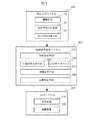
本発明の画像生成/表示装置は、図1に示すように、画像の生成および音響の生成を行なうための仮想世界表現システム200と、このシステム200に対して、指示を入力するための指示入力システム100と、仮想世界表現システム200で生成された画像および音響を可視化および可聴化して出力するための出力システム300とを有する。
【0015】
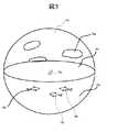
本発明の画像生成/表示装置は、仮想世界表現システム200において、少なくとも1のオブジェクトと、それが存在する環境とを含む仮想世界を予め用意して、その仮想世界の少なくとも一部を可視的に表示するための画像を生成する。ここでの仮想世界は、まったくの仮想的な世界であっても、また、実世界をモデル化した世界であってもよい。例えば、図3に示すような仮想世界を設定することができる。図3は、仮想世界の一例を示す概念図である。出力システム300は、生成された画像を表示する。また、本発明の画像生成/表示装置は、指示入力システム100において、仮想世界表現システム200に対する指示を入力する。この指示は、ジェスチャなどの身振りによるものを対象とする。
【0016】
オブジェクトは、人、動物、物等の他、架空の生物、人工的に創造された仮想生命体等のいずれであってもよい。もちろん、これらの一種または二種以上が混在してもよい。また、同一種のオブジェクトが複数存在していてもよい。例えば、図3では、イルカを模擬した水棲生物の例が示されている。同図では、オブジェクトObが3つある例を示している。
【0017】
環境は、それらのオブジェクトが存在する場所であり、例えば、地球、他の惑星、衛星、未知の天体等、それらにおける特定の地域、建造物の内部、移動体の内部などが挙げられる。一例を挙げれば、図3に示すように、海Seと空Skとで構成される空間が環境として与えられている。空Skには、背景画像Bgとして雲が定義されている。なお、環境には、時刻の要素も含ませることができる。例えば、時間の経過に伴う変化、具体的には、季節の変化、加齢による変化等がある。
【0018】
また、まったくの仮想的な環境を構築してもよい。例えば、物理法則に特定の仮定または制限を設けることにより、通常では実在し得ない性質を持つように定義された空間で構成される世界等が挙げられる。例えば、光の速度が異常に遅い空間、重力が位置によって著しく異なる空間等が挙げられる。もちろん、実際の地形、景観等を反映したものであってもよい。この例としては、例えば、ナビゲーションシステムが挙げられる。
【0019】
画像の生成は、仮想世界全体であっても、一部であってもよい。仮想世界の大きさが、オブジェクトの大きさに比べて十分大きい場合には、一部を切り出して表示することが好ましい。この場合、可視化する部分を指定することもできる。例えば、カメラ位置を、仮想世界の予め定めた位置、オブジェクトの近傍位置、オブジェクトの視点位置、オブジェクトを追跡する位置等が設定できる。また、立体視することができるように設定してもよい。
【0020】
図4に、カメラ位置の設定例を示す。図4の例では、カメラは、固定カメラCp1と、オブジェクト中心カメラCp2と、オブジェクト追尾モードカメラCp3と、オブジェクト視点カメラCp4の4台が設定されている。画像を表現する際には、これらのうちいずれかが指定されて、その視点からの仮想世界の画像が表現される。固定カメラCp1は、位置が仮想世界の原点Oを基準とする仮想世界座標系で規定され、仮想世界の原点Oから一定の距離にある固定位置Pに置かれ、方向が原点Oを臨む。オブジェクト中心カメラCp2は、オブジェクトObの中心位置Opを固定カメラCp1と同じ距離および平行な方向で臨む。オブジェクト追尾モードカメラCp3は、時刻tにおけるオブジェクトObの中心位置Opからdtだけ過去の時点である、時刻(t−dt)におけるオブジェクトObの中心位置Opに置かれて、オブジェクトを追尾する状態で臨む。オブジェクト視点カメラCp4は、オブジェクトObの視点(具体的には、例えば、オブジェクトObの中心位置Op)からオブジェクトの進行方向の一定距離だけ先の位置を臨む。これにより、ユーザの好みの視点でオブジェクトを観察することができる。
【0021】
本発明では、画像のほかに、音響を併せて出力するように構成することができる。音響は、環境の状態によって生じる効果音、オブジェクト自体が発する音、音楽等がある。また、その仮想世界についての説明を行なうためのナレーション、操作の仕方を指示するガイドメッセージ等が挙げられる。オブジェクトが発する音には、例えば、台詞、感情表現音、応答を示す応答音等がある。応答音は、例えば、オブジェクトが指示を了解したことを表現するための音、指示を了解できなかったことを示す音等が挙げられる。また、オブジェクトと環境との相互作用によって発生する音として、オブジェクトが環境に作用したときの衝撃音、例えば、水棲生物がジャンプして水上に出る際の音、ジャンプした水棲生物が水に戻る際の衝撃音等が挙げられる。音自体としては、そのオブジェクトに定義されている音を用いて、例えば、特定の鳴き声として生成することができる。このような音響を加えることによって、オブジェクトの動作にリアリティを増加することが可能となる。また、台詞、感情表現等が発せられると、そのオブジェクトとあたかも対話できるかのようにユーザに感じさせることができて、好ましい。
【0022】
次に、本発明の各部の概要について、図面を参照して説明する。
【0023】
仮想世界表現システム200は、仮想世界に含まれる各オブジェクトおよび環境と、それらを臨むカメラとについて、それらの状態を設定する状態設定手段210と、状態設定手段210に設定される状態に基づいて仮想世界の画像を生成する画像生成手段240とを備える。本発明では、これらの他に、例えば、仮想世界においてオブジェクトの動きにともなって環境に付随的に生ずる効果を生成するための付随効果生成手段220と、オブジェクト、環境および付随効果を生成するための画像データを格納するCGデータベース230と、音響発生を行なうための音響を生成するための音響発生手段250とを備える。
【0024】
状態設定手段210は、例えば、図2に示すように、指示入力手段100から送られるコマンドを受け取ると、そのコマンドの内容を解釈して、そのコマンドが、オブジェクト、環境およびカメラのいずれに関するものかを判定するコマンド解釈部211と、そのコマンドがオブジェクトに関するものであるとき、オブジェクトを特定の状態とするための指示、例えば、位置、運動の種別等の設定を行なうオブジェクト情報を生成して、出力するオブジェクト設定手段212と、そのコマンドがカメラに関するものであるとき、カメラの位置および方向を設定するカメラ情報を生成して、出力するカメラ設定手段213と、そのコマンドが環境に関するものであるとき、背景、時刻、天候等の環境の状態を設定する環境情報を生成して、出力する環境設定手段214とを有する。
【0025】
オブジェクト設定手段212は、オブジェクトごとに、それぞれがとるべき状態を記述するオブジェクトの内部状態情報の設定および変更を行なう。内部状態情報は、状態の新たな設定およびその設定された状態が実行に移されたとき更新されるように設定することができる。ただし、新たに設定された状態が、それ迄に設定されている状態の実行に支障を与えないものであるときは、その新たな状態の設定がそれより前に設定された状態と併存するようにしてもよい。そして、新たに設定された状態が、それ迄に設定されている状態の実行に支障を与えるとき、例えば、矛盾する命令等が設定された場合には、内部状態は、新たに設定された状態に更新される。また、オブジェクトが設定された内部状態情報を用いて対応する動作の実行に移ったとき、この内部状態情報は、リセットされる。従って、内部状態情報として、その一部または全部に、なにも設定されていない場合もあり得る。その場合には、オブジェクトは、システムが予め持っている運動状態となる。この内部状態としては、例えば、移動、ターン、ジャンプ、静止、回転等の各種命令の設定がある。また、運動の大きさ、運動速度等のオブジェクトの運動の程度を記述する情報を、属性情報として併せて設定することができる。
【0026】
また、オブジェクト設定212は、オブジェクトが発する音の情報も設定することができる。この設定された音の情報は、音響発生手段250に送られる。また、上記オブジェクト情報には、オブジェクトの動作にともなって発生するオブジェクト動作付随音響を示す情報も設定可能である。このオブジェクト付随音響を示す情報は、音響発生手段250に供給される。オブジェクト付随音響としては、例えば、風の音、波の音等がある。
【0027】
カメラ設定手段213は、仮想世界を観察する際のカメラ位置および方向を設定する。このカメラ位置は、仮想世界の原点を基準とする仮想世界座標系を構成するX軸、Y軸およびZ軸の各座標で定義される位置と、それらの軸に対する傾きα、βおよびγとで設定される。なお、カメラ位置としては、例えば、上述した4種類がある。また、カメラ情報には、カメラの設定されている位置が水上か、水中かの別を示す情報が含まれる。これは、カメラの位置によって、効果音が異なるためである。このカメラが水上か水中かの別を示す情報は、音響発生手段250に与えられる。
【0028】
環境設定手段214は、仮想世界自体の環境およびオブジェクトが置かれる環境の状態を設定するためのものである。ここでは、環境の周期変化、経時変化、ランダム変化等のほか、意図的な変化等のように種々あり得る。環境の状態のよって効果音等が変化するので、その情報が音響発生手段250に送られる。
【0029】
付随効果生成手段220は、オブジェクト情報を受けて、オブジェクトの動きが環境の一部分に与える変化を生成する。これは、例えば、オブジェクトとして、水棲生物が水面でジャンプして、水面に再突入したとき生じるしぶき、波紋、泡等、また、オブジェクトが水面近くで移動するときに生じる航跡等を、オブジェクトの運動に起因して環境に生じる局部的変化を付随効果として表現するために生成される。この付随効果により、オブジェクトの運動のリアリティを増加することができる。図5は、これらの付随効果の一例を示す。同図(a)は、オブジェクトObが水面下から水面上に飛び出すジャンプを行なった際のしぶきおよび波紋を示す。同図(b)は、オブジェクトObが水面上から水面に飛び込む着水を行なった際のしぶき、泡および波紋を示す。同図(c)は、オブジェクトObが水面またはその近傍を移動する際に生じる航跡およびしぶきを示す。
【0030】
CGデータベース230は、オブジェクト、環境および付随効果のそれぞれを画像表現する際に用いる基本データが格納される。
【0031】
基本データのうち、オブジェクトに関するデータとしては、各オブジェクトの基本的な形態および運動を示すためのデータ、例えば、骨格、外形等の形態データおよび運動時の各部の動きを示すモーションデータと、そのオブジェクトの持つ性質、例えば、重量、色、性格、経時変化情報等の属性情報とがある。経時変化情報は、例えば、オブジェクトの年齢の変化を規定した情報である。具体的には、時刻変化に対応させてオブジェクトを加齢させるための情報、および、それにともなって変化する事項を定めた情報等がある。加齢と共に変化する事項とは、例えば、形態の大きさ、重量、色、性格等が挙げられる。
【0032】
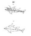
形態データとしては、例えば、図7(a)、図8(a)および図8(b)に示すような、オブジェクトObの外面を多角形fで近似して表した形状データと、図7(b)に示すような、オブジェクトObの全体の形態変化を決定するためのオブジェクトのスケルトンSnを規定するスケルトンデータとが挙げられる。形状データは、図8(b)に示すように、各多角形f1,f2,f3…のように、それぞれを構成する頂点Vの定義と、当該オブジェクトObのローカル座標系で表記される各頂点Vの座標と、各頂点Vの、スケルトンSnを構成する各骨についての動きに対する関係率を表すデータとを有する。
【0033】
モーションデータとしては、図9(a)および(b)に示すように、オブジェクトの動きに対するスケルトンの各骨(スケルトン1…スケルトンn)の角度の時間変化を示す情報が挙げられる。図9(a)は、オブジェクトが遊泳する場合の基本モーションを示している。また、図9(b)は、オブジェクトがターンする場合の基本モーションを示している。
【0034】
環境に関するデータとしては、当該仮想世界の時刻を示す時刻情報、環境における自然現象を表す情報、環境の経時変化を表す情報と、それらの情報に応じて環境をどのような画像に表現すべきかを示す画像変化情報とが挙げられる。時刻情報としては、例えば、その仮想世界に定義されたカレンダ、時刻等が挙げられる。環境における自然現象としては、気象等の時々刻々変化する現象の情報と、地震、火山噴火等のように、稀に生じる現象の情報と、季節の変化、一日の変化等の周期性を示す情報等がある。画像変化情報は、例えば、一日の変化を表す場合、画面の明るさを夜明けから日没までを明るくし、日没から夜明けまでを暗くすることを指示する情報、および、環境を照らす照明のスペクトル変化を示す情報が挙げられる。
【0035】
付随効果に関するデータとしては、オブジェクトの動作にともなって生じるべき環境の局部的変化についての変化パターン、局部変化を発生させるための画像要素、付随効果を発生させるための物理法則等が挙げられる。変化パターンとしては、例えば、図6の状態遷移図に示されるような、オブジェクトの動作に伴う付随効果の対応を示すデータが挙げられる。画像要素としては、例えば、図5に示すような、しぶき、波紋、航跡等を発生させるための基本的な画像データがある。物理法則としては、水面の波の生成および伝搬を記述する法則、しぶきの飛散を示す運動方程式等が挙げられる。
【0036】
画像生成手段240は、オブジェクト、環境、および、付随効果についてそれぞれの近い将来の状態を求め、求められた状態に基づいて、時々刻々、画像を生成し、それらを合成する。画像は、逐次生成され、全体として動画像を形成する。なお、静止画像を形成するようにしてもよい。また、画像生成手段240は、現在表示されている画像を生成するためのデータと、オブジェクト設定情報に何も指定されていない場合におけるオブジェクトの運動に関する情報を記憶している。なお、この何も指定されていない場合のオブジェクトの運動に関する情報は、CGデータベース230に格納してもよい。
【0037】
画像生成手段240は、オブジェクト設定手段212で設定されているオブジェクト情報に基づいて、オブジェクトの近い将来の状態を求める。そして、この近い将来の情報と、カメラ情報とを参照して、オブジェクトの画像を生成する。また、環境情報によって指定される次の環境の状態を、CGデータベース230を参照して求め、カメラ情報を参照して、環境の画像を生成する。さらに、付随効果手段220によって生成された付随効果について、カメラ情報を参照して、画像を生成する。そして、オブジェクトの状態の決定は、予め定義されている運動方程式と、オブジェクト情報とに基づいて行なわれる。例えば、オブジェクトが水面からジャンプする場合には、オブジェクトが水中から飛び出すに必要な速度、角度等を求めると共に、水上での落下軌道を求め、着水位置および着水速度を求める。これらの情報に基づいて、次の画像の状態を決める。
【0038】
音響発生手段250は、オブジェクトの状態に併せて、オブジェクトが発する音、背景音、ナレーション、ガイドメッセージ、音楽等の音響情報を生成する。オブジェクトが発する音、ナレーションおよびガイドメッセージについては、例えば、予め録音または合成して生成した音素片データと、台詞、感情表現音、応答音、ナレーション、ガイドメッセージ等の表現に応じた音響を生成すべき音素片の組み合わせを指定するデータとをライブラリ(図示せず)に記録しておく。背景音および音楽は、予め環境にあった音を録音しておき、これを音響のライブラリとして保存しておき、必要に応じて再生するようにすることができる。なお、音の発生源に位置が関係する場合には、その位置を示すデータも併せて記録しておく。また、ライブラリは、CGデータベース230内に設けてもよい。
【0039】
出力システム300は、画像を表示するための表示装置310と、音響を出力するための音響装置320とを有する。表示装置310は、大画面を実現する場合には、大型スクリーンと、それに画像を投影するためのプロジェクタとで構成することができる。もちろん、複数の表示装置を多数配置したマルチビジョンの構成とするともできる。また、通常のCRTディスプレイ、液晶ディスプレイを用いて表示することもできる。また、音響装置320は、ステレオ再生が可能なように、少なくとも2チャンネルの、オーディオアンプとスピーカとで構成される。もちろん、立体的な音響再生を行なうために、マルチチャンネルのオーディオアンプおよびスピーカを用いることもできる。
【0040】
出力システム300としては、ユーザの頭部に装着して、目の前で画像を表示するように構成したヘッドマウンテッドディスプレイ(HMD)を用いることもできる。この場合、首の回転を検出するセンサを設けることにより、ユーザの視線方向を検出し、これに基づいて、カメラ方向を設定することができる。このような出力システムを用いると、ユーザに、あたかも水中に存在するかのような感覚を持たせることができ、リアリティを増大することができる。なお、音響装置320をヘッドホンで構成することもできる。
【0041】
指示入力システム100は、例えば、指示者のジェスチャを撮像して、そのジェスチャに含まれる指示を認識する。ただし、ジェスチャそのものを全体的に把握するのではなく、ジェスチャにともなって移動する特定の画素パターンの移動状態を検出し、その移動状態から特徴量を抽出して、特徴に基づいて指示の認識を行なう。特定の画素パターンを検出することとした理由は、ジェスチャ全体を認識するには、画像の解析処理に負担がかかるので、それを避けるためである。また、指示の開始点を容易に認識できるようにするためでもある。また、移動状態としては、典型的には、例えば、軌跡が挙げられる。この他に、画素パターンの移動速度、軌跡が描かれた空間の範囲の大きさ等を例示することができる。
【0042】
具体的には、本発明では、指示者が、例えば、ペンライト等の発光体を手持ちして、そのペンライトを点灯した状態で、円、縦振り、横振り、8の字、波等の予め定めたジェスチャパターンを空間で描くように、ペンライトの発光点を移動させることにより行なう。これらのジェスチャパターンは、2次元に限らず、3次元であってもよい。
【0043】
ここで、ペンライトのような発光体を用いている理由は、点灯、消灯により指示の開始および終了を明確化することができるからである。従って、画像処理において、少なくとも開始を明確化できるものであれば、指示を行なう道具は、発光体に限られない。例えば、反射率の高い領域を一部に設け、指示を行なうときそれを露出させ、指示を行なわないとき、露出しないようにすることもできる。具体的には、例えば、手袋の指の一部に螢光塗料を塗布しておき、指示を行なうとき、それが塗布されている指を立て、それ以外のときは、その指を折った状態にしておくことによっても実現することができる。また、先端に特定の色を塗布した指揮棒を用意し、指示を行なうとき、先端を露出し、指示を行なわないとき、先端を覆うようにしてもよい。
【0044】
指示入力システムは、例えば、図10に示すように、一定の空間を撮影して画像を取得する撮像手段110と、上記取得された画像に基づいて指示内容を認識すると共に、指示内容を上記仮想世界表現システムに通知する指示内容認識手段130と、指示の開始を判定する指示開始判定手段120とを備える。なお、指示開始判定手段120は、指示の開始が明確である場合、指示開始を明らかにする必要がない場合等の場合には、省略してもよい。
【0045】
撮像手段110は、例えば、画像を時系列で取得する撮像装置と、撮像された画像を処理して、目的の画像データとする画像処理装置とを有する。撮像装置としては、例えば、少なくとも1台のビデオカメラが用いられる。好ましくは、2台のカメラを用いる。カメラを2台用いることで、空間で行なわれる指示を立体的に把握することができる。画像処理装置としては、目的とする特定の画素パターンを強調処理する装置、アナログ/ディジタルコンバータ等の装置を有する。また、カメラを2台用いる場合、2台のカメラの画像を1フレーム分に納めるように処理する装置を用いることができる。
【0046】
図11に、撮像手段の一例を示す。同図に示す撮像手段は、2台の撮像装置111L,111Rと、撮像された画像を処理して、目的の画像データとする画像処理装置112とを有する。
【0047】
指示内容認識手段130と指示開始判定手段120とは、共に情報処理装置で構成される。具体的には、例えば、上記撮像手段において得られた時系列画像を格納するための記憶手段と、それぞれの手段を実現する手順を含むソフトウエアとで構成される。指示開始判定手段は120は、例えば、撮像手段110によって撮像された複数フレームの画像から特定の画素パターンを抽出し、特定の画素パターンが抽出されたとき、指示開始と判定する。指示内容認識手段130は、例えば、図10に示すように、撮像手段110によって撮像された複数フレームの画像から、特定の画素パターンの動きを抽出して、移動状態を検出する移動状態検出手段131と、検出された移動状態から特徴量を抽出する特徴量抽出手段132と、特徴量に基づいてコマンドの内容を判定する指示内容判定手段133と、特徴量抽出および指示内容判定に用いられる特徴量辞書134とを有する。指示内容判定手段133は、特徴量辞書を参照して特徴量に対応するコマンドの判定を行なうコマンド判定手段1331と、特徴量辞書を参照して属性を判定する属性判定手段1332とを有する。特徴量辞書134は、特徴量の抽出の際に用いられるルールを定めている特徴量抽出ルール1341と、特徴量とコマンドとの対応関係を示す特徴量/コマンド対応テーブル1342と、特徴量と属性との対応関係を示す属性判定テーブル1343とを有する。
【0048】
次に、本発明の実施の形態について、さらに詳細に説明する。
【0049】
図11に、本発明の画像生成/表示装置を構成するハードウエアシステム構成の概要を示す。
【0050】
図11に示すハードウエアシステムは、仮想世界表現システム200と、指示入力システム100と、出力システム300とを備える。これらのシステム100,200は、例えば、イーサネット(登録商標)等のネットワークシステム400で接続され、互いに情報の授受を行なうことができる。図11において、指示入力システム100は、撮像手段110を構成するカメラ111L,111Rと、画像処理装置112と、画像処理装置から入力した画像に基づいて指示内容を認識する指示内容認識手段130および指示開始判定手段120を実現するための情報処理装置150とを備える。仮想世界表現システム200は、画像の生成を行なって、RGB信号を出力する情報処理装置であるコンピュータグラフィックス生成装置(以下CG生成装置)260と、音響生成用の情報処理装置280および楽器ディジタルインタフェース(MIDI I/F)290とを有する。出力システム300は、マルチチャネルアンプ321とマルチチャネル対応の複数個のスピーカ322とで構成される。
【0051】
カメラ111L,111Rは、ジェスチャを行なうユーザUの上半身に向けて、ユーザUの左右の斜め前方の上方位置に設置される。また、表示装置310は、このユーザUの前方に配置される。また、スピーカ322は、ユーザUを取り囲むように配置される。これらは、例えば、防音壁を有する場所、例えば、スタジオに設定される。
【0052】
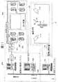
指示入力システム100は、より具体的には、例えば、図12に示すようなハードウエアで構成される。すなわち、撮像手段110として、カメラ111L,カメラ111Rと、カメラから得られた画像について、特定の画素が強調される処理を行なうビデオエフェクタ1121と、カメラで得られた画像をディジタルデータに変換するA/Dコンバータ1122とを有する。また、情報処理装置150は、格納されているプログラムに従って、指示入力処理を実行するための処理を行なうCPU151と、CPU151が実行する各種命令を格納するメモリ152と、取り込んだ画像データ、作業用データ等を格納するためのメモリ153と、特徴量辞書を格納する外部記憶装置154とを有する。CPU151と、メモリ152,153と、外部記憶装置154と、A/Dコンバータ1122とは、バス159で相互に接続される。メモリ152には、システムの全体を制御するための制御手順を格納する全体制御手順格納部1521と、指示開始を検出するための手順を格納する指示開始検出手順格納部1522と、指示内容を認識するための手順を格納する指示内容認識手順格納部1523とが設けられる。また、メモリ153には、作業領域1531と、カメラ111Lの撮像画像を複数フレーム分格納するためのカメラ1撮像動画像格納領域1532と、カメラ111Rの撮像画像を複数フレーム分格納するためのカメラ2撮像動画像格納領域1533とを有する。
【0053】
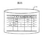
特徴量辞書には、各ジェスチャについての特徴量が規定されている。例えば、図25に示すように、円は、外接矩形の高さ/横の比が“0.5〜2.0”であり、水平線交差数が“2”、垂直線交差数が“2”、および、深さ方向が“なし”が特徴量として規定されている。
【0054】
仮想世界表現システム200は、より具体的には、図13に示すCG生成装置260と、図14に示す情報処理装置280とを備える。
【0055】
CG生成装置260は、図13に示すように、格納されているプログラムに従って、指示入力処理を実行するための処理を行なうCPU261と、CPU261が実行する各種命令を格納するメモリ262と、取り込んだ画像データ、作業用データ等を格納するためのメモリ263と、CGデータベース230を構成するための画像データを格納する外部記憶装置264と、RGB信号変換器270とを有する。CPU261と、メモリ262,263と、外部記憶装置264と、RGB信号変換器270とは、バス269で相互に接続される。メモリ262には、システムの全体を制御するための制御手順を格納する全体制御手順格納部2621と、状態設定を行なうための手順を格納する状態設定手順格納部2622と、画像を生成するための手順を格納する画像生成手順格納部2623とが設けられる。また、メモリ263には、作業領域2631と、付随効果を生成するための付随効果生成手順格納部2632と、画像を生成するためのデータを格納する画像生成データ格納領域2633とを有する。画像生成データ格納領域2633には、次に表示すべき画像を生成するためのデータのほか、複数フレーム過去分のデータも保存している。そして、新しいデータが格納されるごとに、最も旧いデータを廃棄する。
【0056】
情報処理装置280は、図14に示すように、格納されているプログラムに従って、指示入力処理を実行するための処理を行なうCPU281と、CPU281が実行する各種命令を格納するメモリ282と、ライブラリを構成するための音響データを格納する外部記憶装置284と、楽器ディジタルインタフェース(MIDI I/F)290とを有する。CPU281と、メモリ282と、外部記憶装置284と、楽器ディジタルインタフェース(MIDI I/F)290とは、バス289で相互に接続される。メモリ282には、システムの全体を制御するための制御手順を格納する全体制御手順格納部2821と、音響を発生させる音響発生手順を格納する音響発生手順格納部2822と、作業領域2823とを有する。
【0057】
なお、図11のハードウエアシステムでは、仮想世界表現システム200で2台の情報処理装置を用い、また、指示入力システム100で1台の情報処理装置を用いている。しかし、本発明は、使用する情報処理装置の台数に制限されることはない。例えば、仮想世界表現システム200を1台の情報処理装置とすることもできる。また、仮想世界表現システム200と指示入力システム100とを1台の情報処理装置で構成することができる。一方、各システムをさらに細分化して、より多くの情報処理装置で分散処理する構成としてもよい。
【0058】
次に、本発明の画像生成/表示装置について、その動作と共に説明する。なお、以下の説明では、仮想世界として、図3に示すように、オブジェクトObとしてイルカを用い、環境として、海Seと空Skが存在することを想定する。また、指示入力の撮像を行なうためのカメラが2台設置されているものとする。
【0059】
まず、指示入力について説明する。
【0060】
指示入力は、図11および図21に示すように、ユーザUがペンライトPLを手に持ち、このペンライトPLを点灯させて、予め定められた指示動作のうちいずれかについて、ペンライトPLを振るジェスチャを行なって表現することにより実行する。
【0061】
ここで、ジェスチャによる指示について説明する。ジェスチャによる指示には、オブジェクトに対する指示の他、上述した図4に示すカメラの設定指示がある。図15に、ジェスチャによって振られるペンライトPLの光点の軌跡と、指示内容との関係を示す。これらの光点の軌跡の選び方、軌跡と指示内容との対応関係は、任意に定められる。ただし、動作させようとするオブジェクトの行動に対応する軌跡を選ぶことにより、指示するためのジェスチャを覚えやすくするという利点がある。ジェスチャによって指示できるのは、オブジェクトの行動に限られない。例えば、カメラに関する指示も可能である。
【0062】
ユーザUによるジェスチャは、指示入力システム100のカメラ111L,111Rで撮像し、撮像信号は、それぞれビデオエフェクタ1121で画像処理された後、A/Dコンバータ1122でディジタルデータに変換される。ビデオエフェクタ1121では、ペンライトPLの画像が強調されるように、処理される。ディジタルデータに変換された画像データは、情報処理装置150に取り込まれる。以下、情報処理装置150による処理について説明する。
【0063】
図16は、情報処理装置150で実行される指示入力処理の概要を示す。図16によれば、指示入力処理は、ジェスチャ開始、すなわち、指示入力開始の検出(ステップ1000)を、ジェスチャ開始が検出されるまで行なう(ステップ2000)。ジェスチャが開始されると、ジェスチャの認識、すなわち、指示内容の認識処理を行なう(ステップ3000)。そして、認識された指示の内容を仮想世界表現システム200に送る。ここで、カメラ111L,111Rからの画像の取り込みは、図12に示すメモリ152に格納される全体制御手順格納部に格納される全体制御手順をCPU151が実行することにより行なわれる。ジェスチャ開始検出処理およびジェスチャ認識処理は、それぞれ同メモリ152に格納される指示開始検出手順および指示内容認識手順をそれぞれCPU151が実行することにより実現される。
【0064】
上記ジェスチャ開始検出処理(1000)は、図17に示すように行なわれる。すなわち、カメラ111L,111Rで撮像された画像データを、画像処理装置112を介してNフレーム分のディジタルデータとして取り込んで、メモリ153のカメラ1撮像動画像格納領域1532およびカメラ2撮像動画像格納領域1533に格納する(ステップ1100)。次に、格納されたディジタル画像データからペンライトPLの点灯の有無を検出する(ステップ1200)。具体的には、ペンライトPLを撮像して得られる画素パターンを予め定め、この画素パターンの有無を検出して、ペンライトPLの点灯の有無を検出する。
【0065】
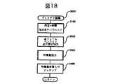
次に、上記ジェスチャ認識処理(3000)は、図18に示すように行なわれる。予め定めたn秒間の動画像の各フレームをメモリ153のカメラ1撮像動画像格納領域1532およびカメラ2撮像動画像格納領域1533に格納する(ステップ3100)。次に、格納されている各フレームについて、ペンライトPLの点灯部分に相当する画素パターンを抽出し、その位置を作業領域1531に格納する(ステップ3200)。これを格納されているすべてのフレームについて行なう。作業領域1531に格納された画素パターンの分布を示すデータから特徴量を抽出する(ステップ3300)。そして、抽出した特徴量を特徴量辞書154に格納される特徴量と比較して、指示内容を判断する(ステップ3400)。
【0066】
特徴量抽出処理(3300)は、図19に示すように、抽出したペンライトPLの点灯部分Pの軌跡Lに対して外接矩形Rtを求める(ステップ3310)。具体的には、図20に示すように、ペンライトPLの光点Pの軌跡Lの垂直方向の最大値および最小値で垂直方向の辺の長さ(高さh)を決定し、かつ、水平方向の最大値および最小値で水平方向の辺の長さ(幅w)を決定して、外接矩形Rtを求める。そして、上記外接矩形Rt内の所定水平線HL・所定垂直線とペンライトの軌跡との交差回数をカウントする(ステップ3320)。ここで、所定水平線HLは、例えば、外接矩形Rtの高さ方向中央の水平線HLとすることができる。同様に、所定垂直線VLは、外接矩形Rtの幅方向中央の垂直線VLとすることができる。
【0067】
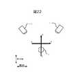
次に、深さ方向の有無を判定する(ステップ3330)。ここで、深さ方向とは、図21に示すように、ユーザUが二つのカメラ111L,111Rに向かってペンライトPLを振る場合の方向である。図21では、CDの方向である。これを上方から見た状態を図22に示す。判定は、カメラ111L,111Rで得られたペンライトPLの点灯部分の軌跡Lの進行方向が同相か、逆相かを調べることにより行なう。図23に示す例は、カメラ111L,111Rで得られた軌跡が、共に同じ向き(同相)を持っているので、軌跡は横方向であることがわかる。一方、図24に示す例は、カメラ111L,111Rで得られた軌跡が、反対の向き(逆相)であるので、軌跡は深さ方向であることがわかる。
【0068】
このようにして得られる特徴量の判定は、図25に示す特徴量辞書を参照して行なう。辞書に規定される条件を満たす場合には、ユーザUのジェスチャは、特徴量辞書に規定されるいずれかのジェスチャであることが判定される。また、図25の辞書には示していないが、各ジェスチャについて、例えば、図15に示すように、それぞれ指示が定義されている。
【0069】
次に、仮想世界表現システム200について、その動作と共にさらに詳細に説明する。なお、以下では、オブジェクトとしてイルカを表示する場合の例について説明する。
【0070】
図26は、仮想世界表現システム200の処理の概要である。このシステムでは、上記指示入力システム100で入力された指示内容(コマンド)についての処理を行なうコマンド処理(ステップ5000)と、コマンド等に基づいてオブジェクトを動作させるためのマクロ動作生成処理(ステップ6000)と、オブジェクトの遊泳状態の処理(ステップ7000)と、ターン処理(ステップ8000)と、オブジェクトの運動処理(ステップ9000)とを有する。仮想世界表現システム200は、この他に、図示していないが、オブジェクト、環境、付随効果について、画像の生成を行なう手段を有する。
【0071】
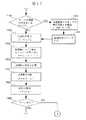
コマンド処理(5000)は、複数種類のコマンドごとに分岐してそれぞれの処理を行なう。図27に示す例は、イルカの動作に関するコマンド、カメラの変更に関するコマンド、環境の変更に関するコマンドの三種のコマンドについての分岐を示す。なお、この例では、指示入力システム100で意味不明の指示が入力された場合には、一応、イルカの動作に関するコマンドとしてある。
【0072】
図27に示すように、指示入力システム100から送られたコマンドがイルカ動作コマンドか否か判定する(ステップ5100)。イルカコマンドの場合、それが正しいコマンドかどうか判定する(ステップ5200)。正しいコマンドの場合、それを示す応答動作をオブジェクトであるイルカに行なわせる(ステップ5300)。この種の応答動作としては、例えば、図28(A)に示すように、オブジェクトであるイルカに、音響で返事をさせること、および、首を振る等の特定の動作を行なうことの少なくとも一方を行なうことにより、コマンド入力に対する応答を明確にすることができる。図28(A)の例では、首を縦に振っている。そして、後述するイルカコマンドの処理を行なう(ステップ5400)。一方、正しいコマンドでない場合には、それを示す応答動作をオブジェクトであるイルカに行なわせる(ステップ5800)。この種の応答動作としては、例えば、図28(B)に示すように、オブジェクトであるイルカに、音響で返事をさせること、および、首を振る等の特定の動作を行なうことの少なくとも一方を行なうことにより、コマンド入力に対する応答を明確にすることができる。図28(B)の例では、首を横に振っている。
【0073】
次に、コマンドがカメラ設定コマンドか否か判定する(ステップ5500)。カメラコマンドの場合、カメラ設定処理5600の処理に移る(ステップ5600)。
【0074】
一方、コマンドが上述したイルカコマンドおよびカメラ設定コマンドのいずれでもない場合には、環境変更処理のコマンドが入力したものとして、環境変更処理を実行する(ステップ5700)。環境の変更処理としては、例えば、背景画像の変更、色の変更等をCGデータベース230(図2参照)を参照して行なう。
【0075】
ここで、イルカコマンドの処理について説明する。イルカコマンドは、オブジェクトの状態を変更するためのコマンドである。具体的には、図29に示すように、オブジェクトの内部状態を設定する(ステップ5410)。オブジェクトの内部状態は、例えば、図30に示すように、各オブジェクトごとに定義される。定義項目としては、例えば、オブジェクトの元気度、運動の目標点、コマンド、衝突可能性等が挙げられる。なお、各オブジェクトは、図31に示すように、現在の運動状態を示すデータを有する。図31に示す運動状態は、オブジェクトの中心位置(X,Y,Z)、X,Y,Zの各軸に対する角度(α,β,γ:方向)および速度(Vx,Vy,Vz)で記述される。
【0076】
次に、カメラ設定処理について説明する。カメラは、カメラ位置Cpおよびカメラ方向Cθで設定する。図32に示すように、本発明では、例えば、固定カメラモード、オブジェクト中心モード、オブジェクト視点モードおよびオブジェクト追尾モードとが設定可能となっている。図32では、各モードにおけるカメラ位置Cpおよびカメラ方向Cθが設定されている。なお、Pは予め設定された位置、θは予め設定された方向、Opはオブジェクトの中心位置、Oθはオブジェクトの方向である。
【0077】
次に、図26のマクロ動作処理について、図33を参照して説明する。図33において、まず、システムは、衝突可能性について判定する。すなわち、オブジェクトが、他の障害物、他のオブジェクトと衝突するか否かの判定を行なう(ステップ6100,6200)。衝突可能性は、相互間の距離と、相互の相対速度を用いて判定する。衝突の可能性がある場合には、衝突を避けるために進行方向を転換する(ステップ6300)。衝突可能性がない場合、内部状態として、オブジェクトについてコマンドが設定されているか否か調べる(ステップ6400)。コマンドがある場合には、コマンド処理を行なう(ステップ6500)。コマンド処理は、追跡処理、ひねり回転処理、ジャンプが用意可能である。コマンドが設定されていない場合には、オブジェクトをデフォルトで自由に動かすことを可能とする。
【0078】
上記追跡処理は、図34に示すように処理される。まず、目標点への距離dを算出する(ステップ6511)。dが微小であるかどうか判定し(ステップ6512)、dが予め定めた値以下であるとき、コマンドが達成されていると判断して、オブジェクトに応答を出力させる。具体的には、オブジェクトの声の情報および位置の情報を音響生成システムに送る(ステップ6516)。その後、内部状態として設定されていたコマンドをクリアする(ステップ6517)。一方、dが大きい場合、目標点への角度θを算出する(ステップ6513)。そして、このθがθ>θcであるとき(ステップ1514)、ターンコマンドを発行する(ステップ6518)。また、θ>θcでないとき(ステップ1514)、距離dから目標速度を設定する(ステップ6515)。ここで、速度は、距離によって設定する。また、目標点に近づいた場合に、速度を落すようにすることができる。
【0079】
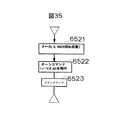
上記ひねり回転処理は、進行方向を軸として、複数回回転することで実現する。すなわち、図35に示すように、いずれかの軸について回転数に相当する角度を設定する(ステップ6521)。そして、この回転を実行させるため、ターンコマンドを発行する(ステップ6522)。なお、turn(θ,t0)のコマンドは、t0秒間にθだけ回転することを示している。このターンコマンドを跛行した後は、コマンドをクリアする(ステップ6523)。
【0080】
上記ジャンプ処理について図36を参照して説明する。ジャンプを行なうには、現状の運動状態でジャンプが可能かを調べる必要がある。ジャンプすることが無理な場合には、一旦水深の深い位置まで戻るように内部状態の設定を行なう。また、ジャンプできる場合には、オブジェクトが水から外に脱出する際に、特定の角度、例えば、45度となるようにする。
【0081】
図36では、まず、オブジェクトの現在の位置、速度および方向で水面に脱出したときの速度Vを推定する(ステップ6531)。現在の位置で加速して得られる速度V0が目標とする速度Vより小さいかどうかを調べる(ステップ6532)。速度V0がVより小さいときは、このままジャンプするには速度が不十分であるから、水深の深い位置Pを設定する(ステップ6537)。そして、P点を通過するコマンドを発行する(ステップ6538)。一方、速度V0がVより小さくないときは、ジャンプ可能であるから、現在の方向と、水面から脱出した角度の差分θを算出する(ステップ6533)。そして、このθ分ターンするターンコマンドを発行する(ステップ6534)。その後、速度を挙げるための目標速度を設定する(ステップ6535)。そして、ジャンプコマンドをクリアする(ステップ6536)。
【0082】
次に、遊泳処理7000について、図37を参照して説明する。図37は、オブジェクトのイルカの遊泳運動を処理する。この例では、イルカは、目標とする遊泳速度が与えられている。そして、常に、目標速度となるように、ドルフィンキックして速度を調節する。キックの最初のタイミング毎に、キックの強さ、周期を決める。通常のキック(強さ1,周期T)で、速度V0になるとして、目標速度がVの場合には、補正係数cを求める。このとき、周期は、T/c、強さはCとする。一回の泳ぎの動きは、モーション基本データを参照して求める。これを強さ周期にしたがって修正する。θは、関節角度である。
【0083】
図37において、システムは、キックの開始t=0またはt>T/cであるか否か判断し(ステップ7100)、該当する場合は、希望速度からキックの補正係数cを算出する(ステップ7200)。そして、経過時間をクリアする(ステップ7300)。その後、ステップ7400において、時刻の正規化を行なう。すなわち、t’=t/cとする。次に、各関節について遊泳モーションの取り出しを行なう(ステップ7500)。この遊泳モーションは、図9(a)に示すように、スケルトンの各部の角度の時間変化で与えられる。そこで、この遊泳モーションを関節の角度を変えて修正する(ステップ7600)。これにより、遊泳状態が変化することになる。この状態で加速度を設定する(ステップ7700)。この加速度は、初期加速度a0に補正係数cの二乗を乗じたものである。ここで、時刻を更新する(ステップ7800)。そして、ターンがあるか否かを調べ(ステップ7900)、ターンがある場合には、次のターン処理8000に移行する。ターンがない場合には、運動処理9000に移行する。
【0084】
次に、ターン処理について図38を参照して説明する。オブジェクトであるイルカは、目標とする方向転換の角度とそれに要する時間が与えられている。方向転換するために身体を曲げる。身体を曲げる関数はモーションの基本データを参照して決める。
【0085】
図38では、まず、ターンの開始(t=0)であるか否か調べる(ステップ8100)。該当する場合は、ターン時間Tの設定、ターン角度α0、β0、γ0の設定を行なう(ステップ8200)。その後、経過時間tのクリアを行なう(ステップ8300)。次に、ターンモーションの取り出しを行なう(ステップ8400)。ここで、ターンモーションは、図9(b)に示すように、スケルトンの各部の角度の時間変化の関数である。ここでも、上記遊泳の場合と同様に、関節の角度を変更して(ステップ8400)、オブジェクトの方向の修正を行なう(ステップ8600)。そして、時刻を更新する(ステップ8700)。
【0086】
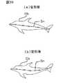
なお、オブジェクトのスケルトンの角度の修正により、オブジェクトの形状が変化するようすを、図39に示す。同図(a)は変形前の状態を示す。また、同図(b)は変形後の状態を示す。
【0087】
次に、運動処理について、図40を参照して説明する。運動処理では、環境における物理法則に従って、イルカの運動を記述する。具体的には、運動方程式に従って、イルカの位置を変更する。また、これにともなって、音響の処理、また、後述する付随効果の処理のための情報を出力する。
【0088】
図40において、まず、通常の状態での推進力をf0としたとき、速度を変えるためのキックによる推進力fを、補正係数cを用いて算出する(ステップ9100)。また、オブジェクトが進行することに対するダンピング力dを、ダンピング係数γとして、d=γ・vにより求める(ステップ9200)。次に加速度aを求める(ステップ9300)。加速度aは、オブジェクトの質量をmとすると、推進力fとダンピング力dとの差とから求めることができる。この加速度aとタイムステップΔtと現在の速度vとから、速度v’を求める(ステップ9400)。さらに、現在の位置Pと速度vとから1タイムステップ後の位置を求める(ステップ9500)。
【0089】
次に、得られた位置Pのy成分について、水平面(y=0)より上か下かで、ジャンプの上昇時か、下降時かを判定する(ステップ9600,9700)。ここで、Py<0、かつ、P’y>0であれば、オブジェクトは、水中から水上にでる(ステップ9650)。一方、Py>0、かつ、P’y<0であれば、オブジェクトは、水上から水中に入る(ステップ9750)。ジャンプの情報は、音響生成手段250に送られる。また、得られた位置Pを付随効果生成手段220に送る(ステップ9800)。
【0090】
以上の処理によって得られるオブジェクトの位置、形態等の情報は、図13に示すメモリ263の作業領域2631に記憶される。CG生成装置は、CPU261がメモリ262に格納される画像生成手順にしたがって、画像を生成する。その際、上記作業領域2631に格納されたデータが用いられる。
【0091】
次に、付随効果生成手段について、さらに詳細に説明する。以下の説明では、付随効果として、オブジェクトの運動がそのオブジェクトが存在する水に与える影響を付随的に付加する場合を例として説明する。ここでは、しぶき、泡、波紋、航跡を取り扱う。これらの例については、図5(a),(b),(c)および図6に示されている。ここでは、それらをどのようにに発生させるかについて説明する。
【0092】
付随効果生成手段220は、例えば、その機能を模式的に示す図41に示すように、水しぶき生成手段221、泡生成手段222、波紋生成手段223および航跡生成手段224と、それらのいずれを用いるかを決定する水の効果選択手段225とを有する。
【0093】
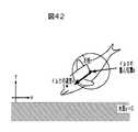
発生機構を説明するため、図42に示すように、オブジェクトを球でモデル化する。すなわち、オブジェクトの中心Pが球の中心となり、オブジェクトは半径rの球で表現される。そして、この球が水中を進行し、また、水中から水上にジャンプし、水上から水中に再突入する際に生じる種々の水の効果を、オブジェクトによる付随効果として利用する。
【0094】
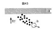
ここで、図6、図43、図44、図45、図46を参照して、オブジェクトの状態に応じて生じる付随効果について整理して説明する。ステージS1の水中では、オブジェクトの進行にともなって泡が生じる。図43は、この状態を示している。すなわち、オブジェクトObが進行するにともなって、後方に泡が発生し、かつ、その泡は、浮力によって浮き上がる。そして、水面に達したとき、消滅する。
【0095】
ステージS2では、ジャンプしてオブジェクトが水面上に達した状態である。この時は、しぶき(図44参照)と、水面の波紋(図45参照)とが生じる。すなわち、オブジェクトObの進行方向後方に、オブジェクトに引っ張られた形でしぶきが伴い、時間の経過にと共に、重力で落下して、消滅する。また、オブジェクトが水面を離れるとき、波紋が発生し、それが時間と共に拡がって行く。ここで、波紋は、色を付して表現し、その色の濃度は、波紋の拡がりにともなって薄くなるようにする。そして、波紋が消えるとき波紋を描く色も透明となる。
【0096】
ステージS3は、オブジェクトが完全に水面上にある状態である。この時には、残留しているしぶきと、拡がっている波紋とが存在することがあり得る。このステージでは、しぶきおよび泡を共に、寿命を設定して、短時間で消えるようにする。
【0097】
ステージS4は、水上から水面にオブジェクトが再突入する場合である。この場合には、波紋、しぶき、泡がそれぞれ生じる。次に、ステージS5では、水面かをオブジェクトが航行している場合である。この時は、航跡と、水面移動時の泡を生じる。図46は、オブジェクトObの移動に伴ってその後方に航跡が生ずることを示している。航跡は、一定の時間間隔発生させる。航跡を示すため一定の色を付している。構成は時間と共に変化する。すなわち、間隔が広くなり、また、色が薄くなる。色が透明になったとき、航跡を消滅させる。
【0098】
ここで、本発明の適用例について説明する。本発明は、ホール等に設置して、観客参加型の映像プログラムの実現に使用することができる。例えば、アニメーション中のオブジェクトにたいして、指示を行なうことができる。また、オーケストラの映像を表示すると共に、音響を放射できるようにして、観客が、指揮棒を振ることにより、それに応答してオーケストラの演奏状態が変化するシステムを実現することに適用できる。
【0099】
本発明は、シアター等の大規模な設備に適用できる他、小規模の装置、例えば、家庭用の小規模のシアターシステム、ゲーム機、車載用の装置等に適用することもできる。
【0100】
以下本発明により期待できる種々の実施態様を列挙する。
【0101】
本発明は、画面内に移動物体(オブジェクト)が表示され、その移動物体が操作者の指示に基づいて、仮想世界の空間内を移動するものに適用できる。その場合、移動規制機を指示することにより、移動物体にたいして、仮想世界内での移動を移動軌跡に基づいて行なわせることができる。
【0102】
本発明では、指示を対象のオブジェクトに与えたとき、指示されたオブジェクトが、その指示を了解したこと、また、指示が了解できなかったことを、画面上での表示、および、音声の少なくとも一方で、通知するように構成することができる。そして、さらに、再指示を促す表示も行なえる。
【0103】
オブジェクトが、仮想世界において、あたかも自律的に判断したり、行動したりできるように、その機能が定義された仮想的な生命体である場合には、指示に対する応答として、その形態の変化、音響によって、応答内容を表現するように構成することができる。仮想的な生命体としては、上述したイルカ等が挙げられる。ここで、形態の変化とは、その仮想的生命体に定義されている感情表現形態から選ばれた動作であり、例えば、首を振ること、逃げること、近寄ること、表情を変えること等が例示される。音響としては、鳴き声、音声等が挙げられる。
【0104】
また、オブジェクトが指示を待っている場合に、それを表現する手段として、等がオブジェクトが、画面上で、ユーザに接近するように待機する構成とすることができる。この際、音響を伴ってもよい。この待機中、オブジェクトは、静止したり、ランダムな運動をしたり、予め定められた運動をしたりできるように構成することもできる。
【0105】
また、指示をジェスチャで行なう場合に、オブジェクトがその指示を受け付けているかどうかを示すため、オブジェクトの向きを変更することができる。また、オブジェクトが複数存在する場合には、その一部または全部の向きを変えることで、指示を受け付けているかどうかを表現するように構成することができる。この場合、向きは、例えば、人工生命体のような場合、顔、視線等が正面を向くようにすることで対応することができる。
【0106】
オブジェクトに、移動、回転等の行動を指示したとき、その動作は、仮想世界に定義される物理法則に従って、決定されるように構成することができる。例えば、その物理法則は、実世界の物理法則をそのまま適用してもよい。例えば、運動量保存の法則、エネルギ保存の法則、エントロピー増大の法則、運動を記述するために運動方程式を用いることができる。また、水中では浮力を与え、水上では、浮力なしで運動させることにより、水中と、水の外での運動状態に変化を与えて、表現することができる。
【0107】
また、オブジェクトは、固有の移動形態を持たせることができる。その場合には、移動が指示されると、移動の仕方の指示を受けずに、固有の移動形態で目的地まで移動する。固有の移動形態としては、例えば、遊泳、飛翔、徒歩等が挙げられる。
【0108】
さらに、オブジェクトに対する指示は、外接矩形で囲むことができる範囲での軌跡によって行なえる。外接矩形で囲むことにより、外接矩形の幅/高さの比と、所定の水平線、または、垂直線との軌跡の交差回数により、ジェスチャした内容を特定することができる。これは、パタンマッチングに比べて、処理のための負荷が少なくてすむ。
【0109】
【発明の効果】
以上説明したように、本発明によれば、オブジェクトの形態によらず、その状態を変化させるための指示の入力が可能である。また、指示の抽出が容易で、かつ、正確に行なえる効果がある。
【図面の簡単な説明】
【図1】本発明の画像生成/表示装置の機能構成の概要を示すブロック図。
【図2】本発明を構成する仮想世界表現システムの機能構成を示すブロック図。
【図3】本発明が適用される仮想世界の一例を示す斜視図。
【図4】仮想世界を可視化するカメラ位置の一例を示す説明図。
【図5】仮想世界においてオブジェクトの運動によって環境に引き起こされる付随的効果の例であって、(a)はオブジェクトがジャンプする場合、(b)はオブジェクトが着水する場合、(c)はオブジェクトが水面を移動する場合を示す説明図。
【図6】仮想世界におけるオブジェクトの状態遷移と付随効果との対応関係を示す説明図。
【図7】(a)オブジェクトの形態を表現するための多角形モデルを説明する説明図。
(b)オブジェクトのスケルトン構造を示す説明図。
【図8】(a)多角形モデルの詳細説明図。
(b)多角形モデルとスケルトンとのデータの対応関係を示すための多角形モデル説明図。
【図9】オブジェクトが運動する場合のスケルトンの角度の時間変化を示し、(a)はオブジェクトが遊泳する場合の基本モーションを示すグラフ、(b)はオブジェクトがターンする場合の基本モーションを示すグラフ。
【図10】指示入力システムの機能構成を示すブロック図。
【図11】本発明の実施に用いることができるハードウエア資源構成の概要を示す説明図。
【図12】指示入力システムを構成するための情報処理装置のハードウエアシステム構成を示すブロック図。
【図13】仮想世界表現システムを構成するためのコンピュータグラフィックス生成装置のハードウエアシステム構成を示すブロック図。
【図14】音響生成システムを構成するための情報処理装置のハードウエアシステム構成を示すブロック図。
【図15】ジェスチャによって振られるペンライトの光点の軌跡と、指示内容との関係を示す説明図。
【図16】指示入力処理用の情報処理装置で実行される指示入力処理の概要を示すフローチャート。
【図17】指示入力処理の一部の手順である指示開始(ジェスチャ開始)検出処理のフローチャート。
【図18】指示(ジェスチャ)認識処理のフローチャート。
【図19】特徴量抽出処理の手順を示すフローチャート。
【図20】ペンライトの光点の軌跡から特徴量を抽出するための外接矩形を設ける例を示す説明図。
【図21】ユーザのジェスチャを2台のカメラで撮像する様子を示す説明図。
【図22】ユーザのジェスチャを2台のカメラで撮像する様子を上面から見た説明図。
【図23】2台のカメラに対して横方向に振ったジェスチャの軌跡の同相性を示す説明図。
【図24】2台のカメラに対して深さ方向に振ったジェスチャの軌跡の逆相性を示す説明図。
【図25】ジェスチャから抽出される特徴量について各種値を規定している特徴量辞書の構成を示す説明図。
【図26】仮想世界表現システムの処理の概要を示すフローチャート。
【図27】コマンド処理の詳細な手順を示すフローチャート。
【図28】指示入力に対するオブジェクトの応答の態様を示す説明図であって、(A)は指示が受け入れられている場合の応答、(B)は指示が受け入れられていない場合の応答をそれぞれ示す。
【図29】オブジェクトの内部状態の設定を示すフローチャート。
【図30】オブジェクトの内部状態の一例を示す説明図。
【図31】オブジェクトの運動状態の一例を示す説明図。
【図32】カメラの設定処理の一例を示すフローチャート。
【図33】マクロ動作生成処理の一例を示すフローチャート。
【図34】オブジェクトの追跡処理の一例を示すフローチャート。
【図35】オブジェクトのひねり回転処理の一例を示すフローチャート。
【図36】オブジェクトのジャンプ処理の一例を示すフローチャート。
【図37】オブジェクトの遊泳処理の一例を示すフローチャート。
【図38】オブジェクトのターン処理の一例を示すフローチャート。
【図39】スケルトンの角度変化によるオブジェクトの形態変形を示す説明図であって、(a)は変形前、(b)変形後を示す。。
【図40】オブジェクトの運動処理の一例を示すフローチャート。
【図41】付随効果生成手段の機能構成の一例を示すブロック図。
【図42】オブジェクトの球モデルによる付随効果の生成を示す説明図。
【図43】球モデルによる泡の生成を示す説明図。
【図44】球モデルによるしぶきの生成を示す説明図。
【図45】球モデルによる波紋の生成を示す説明図。
【図46】球モデルによる航跡の生成を示す説明図。
【符号の説明】
100…指示入力システム、110…撮像手段、111L,111R…カメラ、120…指示開始判定手段、130…指示内容認識手段、131…移動状態検出手段、132…特徴量抽出手段、133…指示内容判定手段、1331…コマンド判定手段、1332…属性判定手段、134…特徴量辞書、200…仮想世界表現システム、210…状態設定手段、211…コマンド解釈、212…オブジェクト設定、213…カメラ設定、214…環境設定、220…付随効果生成手段、230…CGデータベース、240…画像生成手段、250…音響生成手段、300…出力システム、310…表示装置、320…音響装置、Ob…オブジェクト(イルカ)、Cp…カメラ、Sn…スケルトン、U…ユーザ、PL…ペンライト。[0001]
BACKGROUND OF THE INVENTION
The present invention relates to an image generation / display apparatus that generates and displays an image, and more particularly to visually display at least a part of a virtual world including at least one object and an environment in which the object exists. The present invention relates to an image generation / display apparatus capable of generating and displaying an image, receiving an instruction, and changing and displaying a state of at least one object existing in the virtual world.
[0002]
[Prior art]
A device that generates and displays an image includes a device that generates and displays an image of various events that occur in the virtual world including the object, and an event that occurs in the virtual world that models the event that occurred in the real world. There are devices that generate and display as Examples of these devices include devices that display animation, such as game machines and virtual reality systems, and navigation devices. In such an image display apparatus, it may be necessary to give an instruction to an object displayed on the screen, for example, a person, an object, etc., and change the object to a desired state for display. In particular, in game machines and virtual reality systems, it is desirable in terms of improving game performance and reality to give an instruction to an object and change its state.
[0003]
By the way, in the case of instructing an action of an object in an animation, it is necessary to individually input numerical values such as a moving distance and an angle of a joint for elements constituting the form of the object. Therefore, it takes an enormous amount of time to instruct the action of the object. Accordingly, it is naturally difficult to change the image in real time.
[0004]
On the other hand, there is a method of instructing an action by capturing a gesture as a video by using motion capture technology and reflecting the movement in a virtual world. According to this method, a means for imaging a gesture and a means for extracting the motion of the gesture and converting it into the motion of the object are required. However, it is possible to input action instructions at a higher speed than to input numerical values individually, and to change the image in real time.
[0005]
[Problems to be solved by the invention]
However, when an action is instructed using a gesture as it is, the object needs to have a form equivalent to that of a person. That is, in the case of an object having a form different from that of a person, such as a fish, it is difficult to apply a gesture as it is and convert it into an action instruction.
[0006]
Further, when a gesture is captured as a video and used as an action instruction, it is not always easy to identify which of the human movements is the action instruction gesture. For this reason, it is necessary to determine whether or not the action of the person appearing in the video is an instruction. However, this determination is not always easy, and a large burden is placed on the apparatus, and there is a case where an instruction cannot be accurately extracted.
[0007]
A first object of the present invention is to provide an image generation / display apparatus capable of inputting an instruction for changing the state of an object regardless of the form of the object.
[0008]
A second object of the present invention is to provide an image generating / displaying apparatus that can easily extract an instruction and perform it accurately.
[0009]
[Means for Solving the Problems]
In order to achieve the first object, the first aspect of the present invention provides:
In an image generation / display device that generates and displays an image,
A virtual world representation system that creates a virtual world including at least one object and an environment in which the object exists, and generates an image for visually displaying at least a part of the virtual world, and the virtual world representation system An output system for visualizing and outputting the image, and an instruction input system for inputting an instruction to the virtual world representation system,
The above instruction input system is
An imaging means for capturing an image by capturing a certain space;
A moving state of a specific pixel pattern included in the acquired image is detected, a feature amount is extracted from the moving state, and the feature amount is determined in advance.Feature dictionary The instruction content recognition means for recognizing the corresponding instruction as compared with the instruction content and notifying the virtual world representation system of the instruction when the instruction is recognized,
The virtual world representation system is
State setting means for setting the state of each object and environment included in the virtual world;
Set to state setting meansinformation An image generation means for generating an image of a virtual world based on
The state setting means, when the notified instruction relates to any object, to change the setting of the state of the object based on the instruction;
An image generation / display apparatus characterized by the above is provided.
[0010]
In order to achieve the second object of the present invention, in the second aspect of the present invention, in the first aspect, the instruction input system further comprises instruction start determination means for determining start of the instruction,
The instruction start determination means detects the presence or absence of a specific pixel pattern in the image acquired by the imaging means in time series, and determines that the instruction is started when the pixel pattern appears,
The instruction content recognition means recognizes the instruction content after the instruction start determination means determines that the instruction has been started.
An image generation / display device is provided.
[0011]
According to the third aspect of the present invention,
A virtual world representation system for constructing a virtual world including at least one object and an environment in which the object exists, and generating an image for visually displaying at least a part of the virtual world representation system. In an instruction input system for inputting instructions,
Imaging means for capturing a certain space and acquiring images in time series;
Means for detecting a movement state of a specific pixel pattern included in the time-series image acquired by the imaging means;
Means for extracting feature values from the movement state;
The feature amount was determined in advanceFeature dictionary Compared with, search for the instruction corresponding to the extracted feature quantity and respondInstructions An instruction input system is provided, comprising: means for accepting the instruction as an input when the instruction exists, and notifying the virtual world representation system of the instruction.
[0012]
here,In the third aspect, the imaging means detects whether a specific pixel pattern exists in the image acquired in time series, and when the pixel pattern appears, the instruction is started. More means to determineCan be provided. The means for detecting the movement state of the specific pixel pattern is determined after the instruction is started by the means for determining the instruction start, The moving state of the specific image can be detected.
[0013]
DETAILED DESCRIPTION OF THE INVENTION
Embodiments of the present invention will be described below with reference to the drawings.
[0014]
As shown in FIG. 1, an image generation / display apparatus according to the present invention includes a virtual
[0015]
The image generation / display apparatus of the present invention prepares in advance a virtual world including at least one object and an environment in which it exists in the virtual
[0016]
The object may be any person, animal, object, and the like, a fictitious creature, an artificially created virtual creature, and the like. Of course, these 1 type or 2 types or more may be mixed. There may also be a plurality of objects of the same type. For example, FIG. 3 shows an example of an aquatic organism simulating a dolphin. In the figure, an example in which there are three objects Ob is shown.
[0017]
The environment is a place where these objects exist, and includes, for example, the earth, other planets, satellites, unknown celestial bodies, etc., a specific region in them, the inside of a building, the inside of a moving body, and the like. As an example, as shown in FIG. 3, a space composed of the sea Se and the sky Sk is given as an environment. In the sky Sk, a cloud is defined as the background image Bg. The environment can also include a time component. For example, there are changes with the passage of time, specifically seasonal changes, changes due to aging, and the like.
[0018]
Also, a completely virtual environment may be constructed. For example, a world composed of a space defined so as to have a property that cannot normally exist by setting specific assumptions or restrictions to the physical laws. For example, a space in which the speed of light is abnormally slow, a space in which gravity is remarkably different depending on the position, and the like. Of course, it may reflect the actual topography, landscape, and the like. An example of this is a navigation system.
[0019]
The generation of the image may be the entire virtual world or a part thereof. When the size of the virtual world is sufficiently larger than the size of the object, it is preferable to cut out and display a part. In this case, the part to be visualized can also be specified. For example, the camera position can be set to a predetermined position in the virtual world, a position near the object, a viewpoint position of the object, a position for tracking the object, or the like. Moreover, you may set so that it can stereoscopically view.
[0020]
FIG. 4 shows an example of setting the camera position. In the example of FIG. 4, four cameras are set as a fixed camera Cp1, an object center camera Cp2, an object tracking mode camera Cp3, and an object viewpoint camera Cp4. When expressing an image, one of these is designated, and an image of the virtual world from the viewpoint is expressed. The fixed camera Cp1 is defined in a virtual world coordinate system whose position is based on the origin O of the virtual world, is placed at a fixed position P at a certain distance from the origin O of the virtual world, and the direction faces the origin O. The object center camera Cp2 faces the center position Op of the object Ob at the same distance and parallel direction as the fixed camera Cp1. The object tracking mode camera Cp3 is placed at the center position Op of the object Ob at the time (t-dt), which is dt past from the center position Op of the object Ob at the time t, and faces the object tracking state. . The object viewpoint camera Cp4 faces a position ahead from the viewpoint of the object Ob (specifically, for example, the center position Op of the object Ob) by a certain distance in the traveling direction of the object. Thereby, an object can be observed from a user's favorite viewpoint.
[0021]
The present invention can be configured to output sound in addition to images. Sound includes sound effects generated by the state of the environment, sounds emitted by the objects themselves, music, and the like. Further, there are narration for explaining the virtual world, a guide message for instructing how to operate, and the like. Examples of sounds emitted by the object include dialogue, emotion expression sounds, and response sounds indicating responses. Examples of the response sound include a sound for expressing that the object has accepted the instruction, a sound indicating that the instruction has not been accepted, and the like. In addition, the sound generated by the interaction between the object and the environment may be an impact sound when the object acts on the environment, for example, a sound when an aquatic organism jumps out of the water, or a jumped aquatic organism returns to the water. Impact sound. The sound itself can be generated as, for example, a specific call using the sound defined for the object. By adding such sound, it is possible to increase the reality of the motion of the object. In addition, it is preferable that speech, emotional expression, etc. be given to the user as if they were able to interact with the object.
[0022]
Next, the outline of each part of the present invention will be described with reference to the drawings.
[0023]
The virtual
[0024]
For example, as shown in FIG. 2, when the
[0025]
The object setting means 212 sets and changes the internal state information of the object describing the state to be taken for each object. Internal state informationStatus The new setting and its set state can be set to be updated when it is put into practice. However, if the newly set state does not interfere with the execution of the state set so far, the new state setting may coexist with the state set before that. It may be. When the newly set state interferes with the execution of the state set so far, for example, when a contradicting command is set, the internal state is the newly set state. Updated to Further, when the internal state information in which the object is set is used to move to the corresponding operation, the internal state information is reset. Accordingly, there may be cases where nothing is set as a part or all of the internal state information. In this case, the object is in a motion state that the system has in advance. Examples of the internal state include setting various commands such as movement, turn, jump, rest, and rotation. Also, information describing the degree of motion of the object such as the magnitude of motion and the speed of motion can be set together as attribute information.
[0026]
In addition, the object setting 212 can also set information on the sound emitted by the object. The set sound information is sent to the sound generation means 250. In the object information, information indicating an object motion accompanying sound generated in accordance with the motion of the object can be set. Information indicating the object-accompanying sound is supplied to the sound generating means 250. Object-associated soundAs For example, there are wind sounds, wave sounds, and the like.
[0027]
The
[0028]
The environment setting means 214 is for setting the environment of the virtual world itself and the environment in which the object is placed. Here, there may be various changes such as an intentional change in addition to a periodic change in the environment, a change with time, a random change, and the like. Since the sound effects and the like vary depending on the state of the environment, the information is sent to the sound generating means 250.
[0029]
The accompanying effect generation means 220 receives the object information and generates a change that the movement of the object gives to a part of the environment. This is because, for example, as an object, aquatic creatures jump on the surface of the water and re-enter the surface of the water, such as splashes, ripples, bubbles, or wakes that occur when the object moves near the surface of the water. It is generated to express local changes that occur in the environment due to the incidental effects. This accompanying effect can increase the reality of the movement of the object. FIG. 5 shows an example of these accompanying effects. FIG. 4A shows splashes and ripples when the object Ob performs a jump that jumps out from below the water surface. FIG. 4B shows splashes, bubbles, and ripples when the object Ob has landed on the water surface and jumps into the water surface. FIG. 4C shows a wake and a splash generated when the object Ob moves on or near the water surface.
[0030]
The
[0031]
Among the basic data, the data relating to the object includes data for indicating the basic form and movement of each object, for example, form data such as a skeleton and an outer shape, motion data indicating movement of each part during movement, and the object. There are properties such as weight, color, personality, and attribute information such as aging information. The temporal change information is, for example, information that defines a change in the age of the object. Specifically, there are information for aging an object in response to a change in time, information defining items that change along with the information, and the like. Examples of matters that change with aging include the size, weight, color, and personality of the form.
[0032]
As the form data, for example, as shown in FIG. 7A, FIG. 8A, and FIG. 8B, shape data that approximates the outer surface of the object Ob with a polygon f, and FIG. As shown in b), there is skeleton data that defines the skeleton Sn of the object for determining the overall shape change of the object Ob. As shown in FIG. 8 (b), the shape data includes the definitions of the vertices V constituting each of the polygons f1, f2, f3... And the vertices represented in the local coordinate system of the object Ob. V coordinates and data representing the relationship rate of each vertex V with respect to the movement of each bone constituting the skeleton Sn.
[0033]
As the motion data, as shown in FIGS. 9A and 9B, there is information indicating the time change of the angle of each bone of the skeleton (
[0034]
The environmental data includes time information indicating the time of the virtual world, information indicating natural phenomena in the environment, information indicating changes in the environment over time, and what kind of image the environment should be expressed in accordance with those information. Image change information to be displayed. Examples of time information include a calendar and time defined in the virtual world. As natural phenomena in the environment, information on phenomena that change from time to time such as weather, information on phenomena that occur rarely, such as earthquakes, volcanic eruptions, etc., and periodicity such as seasonal changes, daily changes, etc. There is information. For example, when the image change information represents a change of the day, the screen brightness is brightened from dawn to sunset, and information for instructing to darken from sunset to dawn, and lighting that illuminates the environment Information indicating a spectrum change can be given.
[0035]
Examples of the data related to the accompanying effect include a change pattern regarding a local change of the environment that should occur in accordance with the operation of the object, an image element for generating the local change, a physical law for generating the accompanying effect, and the like. As the change pattern, for example, data indicating the correspondence of the accompanying effect accompanying the movement of the object as shown in the state transition diagram of FIG. Examples of the image element include basic image data for generating splashing, ripples, wakes, and the like as shown in FIG. Examples of the physical law include a law that describes the generation and propagation of waves on the water surface, and an equation of motion that indicates splash scattering.
[0036]
The
[0037]
The
[0038]
The sound generation means 250 generates sound information such as sound emitted from the object, background sound, narration, guide message, music, etc. in accordance with the state of the object. For sounds, narration, and guide messages emitted by objects, for example, phoneme segment data generated by recording or synthesizing in advance and sound corresponding to expressions such as speech, emotion expression sounds, response sounds, narration, guide messages, etc. Data specifying a combination of power phone segments is recorded in a library (not shown). The background sound and music can be recorded in advance as sounds suitable for the environment, stored as an acoustic library, and reproduced as necessary. If the position is related to the sound source, data indicating the position is also recorded. The library may be provided in the
[0039]
The
[0040]
As the
[0041]
For example, the
[0042]
Specifically, in the present invention, for example, an instructor holds a light emitter such as a penlight and turns on the penlight, such as a circle, a vertical swing, a horizontal swing, a figure 8, a wave, etc. This is done by moving the light emission point of the penlight so as to draw a predetermined gesture pattern in space. These gesture patterns are not limited to two dimensions, and may be three dimensions.
[0043]
Here, the reason for using a light emitter such as a penlight is that the start and end of the instruction can be clarified by turning on and off. Therefore, in the image processing, the tool for giving an instruction is not limited to the light emitter as long as the start can be clarified. For example, a region having a high reflectance can be provided in a part and exposed when an instruction is given, and not exposed when an instruction is not given. Specifically, for example, a fluorescent paint is applied to a part of a finger of a glove, and when giving an instruction, a finger to which the finger is applied is raised, and in other cases, the finger is folded. This can also be realized. Alternatively, a baton with a specific color applied to the tip may be prepared, and when the instruction is given, the tip is exposed, and when the instruction is not given, the tip may be covered.
[0044]
For example, as shown in FIG. 10, the instruction input system recognizes the instruction content based on the acquired image and the
[0045]
The
[0046]
FIG. 11 shows an example of the imaging means. The imaging unit shown in the figure includes two
[0047]
Both the instruction
[0048]
Next, embodiments of the present invention will be described in more detail.
[0049]
FIG. 11 shows an outline of a hardware system configuration constituting the image generation / display apparatus of the present invention.
[0050]
The hardware system shown in FIG. 11 includes a virtual
[0051]
The cameras 111 </ b> L and 111 </ b> R are installed at diagonally forward positions on the left and right sides of the user U toward the upper body of the user U who performs the gesture. The
[0052]
More specifically, the
[0053]
The feature amount dictionary defines the feature amount for each gesture. For example, as shown in FIG. 25, the circle has a height / lateral ratio of the circumscribed rectangle of “0.5 to 2.0”, the number of horizontal line intersections is “2”, and the number of vertical line intersections is “2”. In addition, “none” in the depth direction is defined as the feature amount.
[0054]
More specifically, the virtual
[0055]
As illustrated in FIG. 13, the
[0056]
As shown in FIG. 14, the
[0057]
In the hardware system of FIG. 11, two information processing apparatuses are used in the virtual
[0058]
Next, the image generation / display apparatus of the present invention will be described together with its operation. In the following explanation,Virtual world As shown in FIG. 3, it is assumed that a dolphin is used as the object Ob, and there are a sea Se and a sky Sk as an environment. In addition, it is assumed that two cameras for capturing an instruction input are installed.
[0059]
First, instruction input will be described.
[0060]
As shown in FIG. 11 and FIG. 21, the instruction input is performed by the user U holding the penlight PL, turning on the penlight PL, and turning on the penlight PL for any of predetermined instruction operations. This is done by performing and expressing a shaking gesture.
[0061]
Here, the instruction by the gesture will be described. The instruction by the gesture includes an instruction to set the camera shown in FIG. FIG. 15 shows the relationship between the locus of the light spot of the penlight PL shaken by the gesture and the instruction content. How to select the locus of these light spots and the correspondence between the locus and the instruction content are arbitrarily determined. However, there is an advantage that it becomes easy to remember a gesture for instructing by selecting a trajectory corresponding to the action of the object to be operated. GestureDirected by What you can do is not limited to object behavior. For example, an instruction regarding a camera can be given.
[0062]
The gesture by the user U is imaged by the
[0063]
FIG. 16 shows an overview of the instruction input process executed by the
[0064]
The gesture start detection process (1000) is performed as shown in FIG. That is, the image data captured by the
[0065]
Next, the gesture recognition process (3000) is performed as shown in FIG. Each frame of the moving image for n seconds determined in advance is captured by the
[0066]
In the feature amount extraction process (3300), as shown in FIG. 19, a circumscribed rectangle Rt is obtained with respect to the locus L of the lit portion P of the extracted penlight PL (step 3310). Specifically, as shown in FIG. 20, the vertical length (height h) is determined by the vertical maximum and minimum values of the locus L of the light spot P of the penlight PL, and The length (width w) of the side in the horizontal direction is determined by the maximum value and the minimum value in the horizontal direction, and the circumscribed rectangle Rt is obtained. Then, the number of intersections between the predetermined horizontal line HL and the predetermined vertical line in the circumscribed rectangle Rt and the penlight locus is counted (step 3320). Here, the predetermined horizontal line HL can be, for example, the horizontal line HL at the center in the height direction of the circumscribed rectangle Rt. Similarly, the predetermined vertical line VL can be the vertical line VL at the center in the width direction of the circumscribed rectangle Rt.
[0067]
Next, the presence / absence of the depth direction is determined (step 3330). Here, the depth direction is a direction when the user U swings the penlight PL toward the two
[0068]
The feature quantity obtained in this way is determined with reference to the feature dictionary shown in FIG. When the conditions specified in the dictionary are satisfied, it is determined that the gesture of the user U is any one of the gestures specified in the feature dictionary. Although not shown in the dictionary of FIG. 25, for each gesture, for example, an instruction is defined as shown in FIG.
[0069]
Next, the virtual
[0070]
FIG. 26 is an overview of the processing of the virtual
[0071]
Command processing (5000) branches for each of a plurality of types of commands and performs each processing. The example shown in FIG. 27 shows branches for three types of commands: a command related to the operation of a dolphin, a command related to a camera change, and a command related to an environment change. In this example, when an instruction having an unknown meaning is input by the
[0072]
As shown in FIG. 27, it is determined whether or not the command sent from the
[0073]
Next, it is determined whether the command is a camera setting command (step 5500). In the case of a camera command, the process proceeds to the camera setting process 5600 (step 5600).
[0074]
On the other hand, when the command is neither the dolphin command nor the camera setting command, the environment change process is executed assuming that the environment change process command is input (step 5700). As the environment change processing, for example, background image change, color change, and the like are performed with reference to the CG database 230 (see FIG. 2).
[0075]
Here, the processing of the dolphin command will be described. The dolphin command is a command for changing the state of the object. Specifically, as shown in FIG. 29, the internal state of the object is set (step 5410). The internal state of the object is defined for each object, for example, as shown in FIG. The definition items include, for example, the spirit level of the object, the target point of motion, the command, the possibility of collision, and the like. Each object has data indicating the current motion state as shown in FIG. The motion state shown in FIG. 31 is described by the center position (X, Y, Z) of the object, angles (α, β, γ: directions) and speeds (Vx, Vy, Vz) with respect to the X, Y, and Z axes. Is done.
[0076]
Next, camera setting processing will be described. The camera is set by the camera position Cp and the camera direction Cθ. As shown in FIG. 32, in the present invention, for example, a fixed camera mode, an object center mode, an object viewpoint mode, and an object tracking mode can be set. In FIG. 32, the camera position Cp and the camera direction Cθ in each mode are set. Note that P is a preset position, θ is a preset direction, Op is a center position of the object, and Oθ is a direction of the object.
[0077]
Next, the macro operation process of FIG. 26 will be described with reference to FIG. In FIG. 33, the system first determines the possibility of collision. That is, it is determined whether or not the object collides with another obstacle or another object (step 6100)., 6200 ). The possibility of collision is determined using the distance between each other and the relative speed of each other. If there is a possibility of collision, the traveling direction is changed to avoid the collision (step 6300). If there is no possibility of collision, it is checked whether or not a command is set for the object as an internal state (step 6400). If there is a command, command processing is performed (step 6500). As the command processing, tracking processing, twist rotation processing, and jump can be prepared. If no command is set, the object can be moved freely by default.
[0078]
The tracking process is performed as shown in FIG. First, the distance d to the target point is calculated (step 6511). It is determined whether or not d is very small (step 6512). When d is equal to or smaller than a predetermined value, it is determined that the command has been achieved, and a response is output to the object. Specifically, the voice information and position information of the object are sent to the sound generation system (step 6516). Thereafter, the command set as the internal state is cleared (step 6517). On the other hand, if d is large, the angle θ to the target point is calculated (step 6513). And when this θ is θ> θc(Step 1514) A turn command is issued (step 6518). When θ> θc is not satisfied(Step 1514) The target speed is set from the distance d (step 6515). Here, the speed is set according to the distance. In addition, the speed can be reduced when approaching the target point.
[0079]
The twist rotation process is realized by rotating a plurality of times around the traveling direction. That is, as shown in FIG. 35, an angle corresponding to the rotational speed is set for any of the axes (step 6521). Then, in order to execute this rotation, a turn command is issued (step 6522). The turn (θ, t0) command indicates that the rotation is θ by t0 seconds. After coasting this turn command, the command is cleared (step 6523).
[0080]
The jump process will be described with reference to FIG. In order to jump, jump in the current exercise stateIs possible It is necessary to investigate. If it is impossible to jump, the internal state is set so as to return to a deep position once. Further, when the object can jump, when the object escapes from the water, a specific angle, for example, 45 degrees is set.
[0081]
In FIG. 36, first, the velocity V when the object escapes to the water surface at the current position, velocity and direction is estimated (step 6531). It is checked whether or not the speed V0 obtained by accelerating at the current position is smaller than the target speed V (step 6532). When the velocity V0 is smaller than V, the velocity P is insufficient for jumping as it is, and therefore a deep water position P is set (step 6537). Then, a command that passes through the point P is issued (step 6538). On the other hand, when the velocity V0 is not smaller than V, the jump is possible, so the difference θ between the current direction and the angle escaped from the water surface is calculated (step 6533). Then, a turn command for turning this θ is issued (step 6534). Thereafter, a target speed for increasing the speed is set (step 6535). Then, the jump command is cleared (step 6536).
[0082]
Next, the
[0083]
In FIG. 37, the system determines whether or not the kick start t = 0 or t> T / c (step 7100), and if applicable, calculates the kick correction coefficient c from the desired speed (step 7200). ). Then, the elapsed time is cleared (step 7300). Thereafter, in
[0084]
Next, turn processing will be described with reference to FIG. The target dolphin is given a target turning angle and the time required for it. Bend your body to change direction. The function to bend the body is determined with reference to the basic data of motion.
[0085]
In FIG. 38, it is first checked whether or not it is the start of a turn (t = 0) (step 8100). If applicable, the turn time T is set and the turn angles α0, β0, γ0 are set (step 8200). Thereafter, the elapsed time t is cleared (step 8300). Next, the turn motion is extracted (step 8400). Here, as shown in FIG. 9B, the turn motion is a function of the time change of the angle of each part of the skeleton. Here again, as in the case of swimming, the angle of the joint is changed (step 8400), and the direction of the object is corrected (step 8600). Then, the time is updated (step 8700).
[0086]
FIG. 39 shows how the shape of the object changes by correcting the angle of the skeleton of the object. FIG. 4A shows a state before deformation. FIG. 5B shows the state after deformation.
[0087]
Next, the exercise process will be described with reference to FIG. In motion processing, dolphin motion is described according to the physical laws of the environment. Specifically, the position of the dolphin is changed according to the equation of motion. In addition, along with this, information for acoustic processing and incidental effect processing described later is output.
[0088]
In FIG. 40, first, assuming that the propulsive force in the normal state is f0, the propulsive force f by the kick for changing the speed is calculated using the correction coefficient c (step 9100). Further, the damping force d with respect to the progression of the object is determined as d = γ · v as a damping coefficient γ (step 9200). Next, acceleration a is obtained (step 9300). The acceleration a can be obtained from the difference between the driving force f and the damping force d, where m is the mass of the object. From this acceleration a, time step Δt, and current speed v, a speed v ′ is obtained (step 9400). Further, a position after one time step is obtained from the current position P and speed v (step 9500).
[0089]
Next, with respect to the y component of the obtained position P, it is determined whether the jump is rising or falling, whether it is above or below the horizontal plane (y = 0) (
[0090]
Information such as the position and form of the object obtained by the above processing is stored in the
[0091]
Next, the accompanying effect generating means will be described in more detail. In the following description, as an incidental effect, a case will be described as an example in which the influence of the movement of an object on the water in which the object exists is incidentally added. Here we deal with splashes, bubbles, ripples and wakes. Examples of these are shown in FIGS. 5 (a), (b), (c) and FIG. Here, how to generate them will be described.
[0092]
For example, as shown in FIG. 41 schematically showing the function, the incidental
[0093]
In order to explain the generation mechanism, an object is modeled as a sphere as shown in FIG. That is, the center P of the object is the center of the sphere, and the object is represented by a sphere having a radius r. The sphere travels in the water, jumps from the water to the water, and uses various water effects generated when the water re-enters the water as the incidental effects by the object.
[0094]
Here, with reference to FIG. 6, FIG. 43, FIG. 44, FIG. 45, and FIG. 46, incidental effects that occur according to the state of the object will be described in an organized manner. In the water of stage S1, bubbles are generated as the object progresses. FIG. 43 shows this state. That is, as the object Ob advances, bubbles are generated backward, and the bubbles are lifted by buoyancy. And when it reaches the water surface, it disappears.
[0095]
In stage S2, the object jumps and reaches the surface of the water. At this time, splash (see FIG. 44) and ripples on the water surface (see FIG. 45) occur. That is, the object Ob is splashed behind the object in the direction of travel, and drops with gravity as time passes and disappears. Also, when the object leaves the water surface, a ripple occurs and spreads with time. Here, the ripples are expressed with colors, and the density of the colors is made lighter as the ripples spread. When the ripple disappears, the color of the ripple is also transparent.
[0096]
Stage S3 is a state in which the object is completely on the water surface. At this time, there may be residual splashes and spreading ripples. In this stage, both the splash and the foam are set to life and disappear in a short time.
[0097]
Stage S4 is a case where the object re-enters the surface of the water from the water. In this case, ripples, splashes and bubbles are generated. Next, in stage S5, the object is navigating the water surface. At this time, a wake and a bubble at the time of water surface movement are produced. FIG. 46 shows that a wake is generated behind the object Ob as the object Ob moves. Wakes are generated at regular time intervals. A certain color is given to indicate the wake. Configuration changes over time. That is, the interval becomes wider and the color becomes lighter. When the color becomes transparent, the wake disappears.
[0098]
Here, an application example of the present invention will be described. The present invention can be installed in a hall or the like and used to realize an audience participation type video program. For example, an instruction can be given to an object being animated. Further, the present invention can be applied to the realization of a system in which an orchestra video is displayed and sound can be radiated so that the performance of the orchestra changes in response to the spectator shaking the baton.
[0099]
The present invention can be applied not only to a large-scale facility such as a theater but also to a small-scale device, for example, a small-scale theater system for home use, a game machine, a vehicle-mounted device, and the like.
[0100]
Listed below are various embodiments that can be expected from the present invention.
[0101]
The present invention can be applied to a case where a moving object (object) is displayed on the screen and the moving object moves in the space of the virtual world based on an instruction from the operator. In that case, by instructing the movement restricting machine, the moving object can be moved in the virtual world based on the movement trajectory.
[0102]
In the present invention, when an instruction is given to a target object, the instructed object understands the instruction, and that the instruction cannot be accepted is displayed on the screen and / or audio. And can be configured to notify. Further, a display for prompting re-instruction can be performed.
[0103]
If the object is a virtual life form whose function is defined so that it can be autonomously judged and acted in the virtual world, the change of its form, sound, etc. Thus, the response content can be expressed. Examples of the virtual life form include the dolphins described above. Here, the change in form is an action selected from the emotional expression forms defined in the virtual life form, for example, shaking the head, running away, approaching, changing the facial expression, etc. Is done. Examples of sound include squeal and voice.
[0104]
In addition, when the object is waiting for an instruction, as a means for expressing it, the object can wait so that the object approaches the user on the screen. At this time, sound may be accompanied. During this waiting time, the object can be configured to be stationary, perform a random motion, or perform a predetermined motion.
[0105]
Further, when an instruction is given by a gesture, the direction of the object can be changed to indicate whether the object has accepted the instruction. If there are multiple objects, part of them orAll By changing the direction, it can be configured to express whether or not an instruction is accepted. In this case, for example, in the case of an artificial life form, it can be dealt with by making the face, the line of sight, etc. face the front.
[0106]
When an action such as movement or rotation is instructed to an object, the operation can be determined according to a physical law defined in a virtual world. For example, the physical laws of the real world may be applied as they are. For example, the law of conservation of momentum, the law of conservation of energy, the law of entropy increase, and the equation of motion can be used to describe motion. Moreover, by giving buoyancy in the water and exercising without buoyancy on the water, it is possible to change and express the motion state in the water and outside the water.
[0107]
An object can have a unique movement form. In that case, when the movement is instructed, it moves to the destination in a specific movement form without receiving an instruction on how to move. Specific movement forms include, for example, swimming, flying, walking and the like.
[0108]
Furthermore, an instruction for an object can be given by a trajectory within a range that can be enclosed by a circumscribed rectangle. By enclosing with a circumscribed rectangle, the content of the gesture can be specified by the ratio of the width / height of the circumscribed rectangle and the number of intersections of the trajectory with a predetermined horizontal line or vertical line. This requires less processing load than pattern matching.
[0109]
【The invention's effect】
As described above, according to the present invention, it is possible to input an instruction for changing the state regardless of the form of the object. In addition, there is an effect that the instruction can be extracted easily and accurately.
[Brief description of the drawings]
FIG. 1 is a block diagram showing an outline of a functional configuration of an image generation / display apparatus according to the present invention.
FIG. 2 is a block diagram showing a functional configuration of a virtual world expression system constituting the present invention.
FIG. 3 is a perspective view showing an example of a virtual world to which the present invention is applied.
FIG. 4 is an explanatory diagram showing an example of a camera position for visualizing a virtual world.
FIGS. 5A and 5B are examples of incidental effects caused to the environment by movement of an object in a virtual world, where FIG. 5A shows a case where the object jumps, FIG. 5B shows a case where the object lands, and FIG. Explanatory drawing which shows the case where a water moves.
FIG. 6 is an explanatory diagram showing a correspondence relationship between an object state transition and an accompanying effect in a virtual world.
FIG. 7A is an explanatory diagram illustrating a polygon model for expressing the form of an object.
(B) Explanatory drawing which shows the skeleton structure of an object.
FIG. 8A is a detailed explanatory diagram of a polygon model.
(B) The polygon model explanatory drawing for showing the correspondence of the data of a polygon model and a skeleton.
9A and 9B show temporal changes in the skeleton angle when the object moves, FIG. 9A is a graph showing basic motion when the object swims, and FIG. 9B is a graph showing basic motion when the object turns. .
FIG. 10 is a block diagram showing a functional configuration of the instruction input system.
FIG. 11 is an explanatory diagram showing an outline of a hardware resource configuration that can be used to implement the present invention.
FIG. 12 is a block diagram showing a hardware system configuration of an information processing apparatus for configuring an instruction input system.
FIG. 13 is a block diagram showing a hardware system configuration of a computer graphics generation apparatus for configuring a virtual world expression system.
FIG. 14 is a block diagram showing a hardware system configuration of an information processing apparatus for configuring the sound generation system.
FIG. 15 is an explanatory diagram showing the relationship between the locus of the light spot of a penlight shaken by a gesture and the instruction content;
FIG. 16 is a flowchart showing an overview of instruction input processing executed by the information processing apparatus for instruction input processing;
FIG. 17 is a flowchart of an instruction start (gesture start) detection process which is a part of the instruction input process.
FIG. 18 is a flowchart of instruction (gesture) recognition processing;
FIG. 19 is a flowchart showing a procedure of feature amount extraction processing;
FIG. 20 is an explanatory diagram illustrating an example in which a circumscribed rectangle for extracting a feature amount from a locus of light points of a penlight is provided.
FIG. 21 is an explanatory diagram illustrating a state in which a user's gesture is captured by two cameras.
FIG. 22 is an explanatory view of a state where a user's gesture is picked up by two cameras as viewed from above.
FIG. 23 is an explanatory diagram showing the in-phase property of the trajectory of a gesture shaken horizontally with respect to two cameras.
FIG. 24 is an explanatory diagram showing the reverse phase of the trajectory of a gesture shaken in the depth direction with respect to two cameras.
FIG. 25 is an explanatory diagram showing a configuration of a feature dictionary that defines various values for feature extracted from a gesture.
FIG. 26 is a flowchart showing an outline of processing of the virtual world expression system.
FIG. 27 is a flowchart showing a detailed procedure of command processing.
FIGS. 28A and 28B are explanatory diagrams showing aspects of an object response to an instruction input, where FIG. 28A shows a response when the instruction is accepted, and FIG. 28B shows a response when the instruction is not accepted; .
FIG. 29 is a flowchart showing setting of an internal state of an object.
FIG. 30 is an explanatory diagram illustrating an example of an internal state of an object.
FIG. 31 is an explanatory diagram showing an example of the motion state of an object.
FIG. 32 is a flowchart showing an example of camera setting processing;
FIG. 33 is a flowchart illustrating an example of a macro operation generation process.
FIG. 34 is a flowchart showing an example of object tracking processing;
FIG. 35 is a flowchart showing an example of object twist rotation processing;
FIG. 36 is a flowchart showing an example of object jump processing;
FIG. 37 is a flowchart showing an example of an object swimming process.
FIG. 38 is a flowchart showing an example of object turn processing;
FIGS. 39A and 39B are explanatory diagrams showing deformation of an object by changing the angle of the skeleton, where FIG. 39A shows before deformation and FIG. 39B shows after deformation; .
FIG. 40 is a flowchart illustrating an example of an object motion process.
FIG. 41 is a block diagram illustrating an example of a functional configuration of an accompanying effect generation unit.
FIG. 42 is an explanatory diagram showing generation of an accompanying effect by a sphere model of an object.
FIG. 43 is an explanatory diagram showing generation of bubbles by a sphere model.
44 is an explanatory diagram showing generation of splash by a sphere model. FIG.
FIG. 45 is an explanatory diagram showing generation of ripples using a sphere model.
FIG. 46 is an explanatory diagram showing generation of a wake by a sphere model.
[Explanation of symbols]
DESCRIPTION OF
Claims (4)
Translated fromJapanese少なくとも1つのオブジェクトと、そのオブジェクトが存在する環境とを含む仮想世界を構築すると共に、その少なくとも一部を可視的に表示するための画像を生成する仮想世界表現システムと、仮想世界表現システムによって生成された画像を可視化して出力する出力システムと、上記仮想世界表現システムに対して指示を入力するための指示入力システムとを備え、
上記指示入力システムは、
一定の空間を撮影して画像を取得する撮像手段と、
上記取得された画像に含まれる特定の画素パターンの移動状態を検出して、その移動状態から特徴量を抽出し、その特徴量を予め定めた特徴量辞書と比較して対応する指示の認識を行ない、指示が認識できたとき、その指示を上記仮想世界表現システムに通知する指示内容認識手段とを備え、
上記仮想世界表現システムは、
仮想世界に含まれる各オブジェクトと環境とについて、それらの状態を設定する状態設定手段と、
状態設定手段に設定される状態に基づいて仮想世界の画像を生成する画像生成手段とを備え、
上記状態設定手段は、上記通知された指示がいずれかのオブジェクトに関するものであるとき、当該オブジェクトの状態の設定をその指示に基づいて変更すること、
を特徴とする画像生成/表示装置。In an image generation / display device that generates and displays an image,
A virtual world representation system that creates a virtual world including at least one object and an environment in which the object exists, and generates an image for visually displaying at least a part of the virtual world, and the virtual world representation system An output system for visualizing and outputting the image, and an instruction input system for inputting an instruction to the virtual world representation system,
The above instruction input system is
An imaging means for capturing an image by capturing a certain space;
The movement state of a specific pixel pattern included in the acquired image is detected, the feature amount is extracted from the movement state, and the feature amount is compared with a predeterminedfeature amount dictionary to recognize the corresponding instruction. Performing instruction content recognition means for notifying the virtual world representation system of the instruction when the instruction is recognized,
The virtual world representation system is
State setting means for setting the state of each object and environment included in the virtual world;
Image generating means for generating an image of the virtual world based on thestate set in the state setting means,
The state setting means, when the notified instruction relates to any object, to change the setting of the state of the object based on the instruction;
An image generation / display device characterized by the above.
該指示開始判定手段は、撮像手段が時系列に取得した画像中に特定の画素パターンの有無を検知し、当該画素パターンが現われたとき、指示が開始されたと判定し、
指示内容認識手段は、上記指示開始判定手段が指示が開始されたと判定した後、指示内容の認識を行なうこと
を特徴とする画像生成/表示装置。The instruction input system according to claim 1, further comprising instruction start determination means for determining start of the instruction,
The instruction start determination means detects the presence or absence of a specific pixel pattern in the image acquired by the imaging means in time series, and determines that the instruction is started when the pixel pattern appears,
The instruction content recognizing means recognizes the instruction content after the instruction start determining means determines that the instruction has been started.
一定の空間を撮影して時系列に画像を取得する撮像手段と、
撮像手段が取得した時系列の画像中に含まれる特定の画素パターンの移動状態を検出する手段と、
その移動状態から特徴量を抽出する手段と、
その特徴量を予め定めた特徴量辞書と比較して、抽出された特徴量に対応する指示を検索して、対応する指示が存在するとき、当該指示を入力として受け付けて、当該指示を上記仮想世界表現システムに通知する手段とを備えることを特徴とする指示入力システム。An instruction is input toa virtual world representation system that constructs a virtual world including at least one object and an environment in which the object exists, and generates an image for visually displaying at least a part of the virtual world. In the instruction input system for
Imaging means for capturing a certain space and acquiring images in time series;
Means for detecting a movement state of a specific pixel pattern included in the time-series image acquired by the imaging means;
Means for extracting feature values from the movement state;
The feature quantity is compared with a predeterminedfeature quantity dictionary , an instruction corresponding to the extracted feature quantity is searched, and when there is a correspondinginstruction , theinstruction is accepted as an input, and the instruction is An instruction input system comprising means for notifying the world representation system.
上記特定の画素パターンの移動状態を検出する手段は、上記指示開始を判定する手段により指示が開始されたと判定された後、当該特定の画像の移動状態を検出することを特徴とする指示入力システム。According to claim 3,detects whetherthe imaging means is a specific pixel pattern present in the image obtained in timeseries, when the pixel pattern appears, further comprising means for determiningthat the instruction has been started,
The means for detecting the movement state of the specific pixel pattern detects the movement state of the specific imageafter it is determined that the instruction is started by the means for determining the start of the instruction. .
Priority Applications (2)
| Application Number | Priority Date | Filing Date | Title |
|---|---|---|---|
| JP26604295AJP3745802B2 (en) | 1995-10-13 | 1995-10-13 | Image generation / display device |
| US08/731,163US5966129A (en) | 1995-10-13 | 1996-10-10 | System for, and method of displaying an image of an object responsive to an operator's command |
Applications Claiming Priority (1)
| Application Number | Priority Date | Filing Date | Title |
|---|---|---|---|
| JP26604295AJP3745802B2 (en) | 1995-10-13 | 1995-10-13 | Image generation / display device |
Publications (2)
| Publication Number | Publication Date |
|---|---|
| JPH09115004A JPH09115004A (en) | 1997-05-02 |
| JP3745802B2true JP3745802B2 (en) | 2006-02-15 |
Family
ID=17425592
Family Applications (1)
| Application Number | Title | Priority Date | Filing Date |
|---|---|---|---|
| JP26604295AExpired - Fee RelatedJP3745802B2 (en) | 1995-10-13 | 1995-10-13 | Image generation / display device |
Country Status (2)
| Country | Link |
|---|---|
| US (1) | US5966129A (en) |
| JP (1) | JP3745802B2 (en) |
Families Citing this family (89)
| Publication number | Priority date | Publication date | Assignee | Title |
|---|---|---|---|---|
| EP0890926A1 (en) | 1997-01-24 | 1999-01-13 | Sony Corporation | Device, method, and medium for generating graphic data |
| US6518989B1 (en) | 1997-01-24 | 2003-02-11 | Sony Corporation | Graphic data generating apparatus, graphic data generation method, and medium of the same |
| KR20000064773A (en) | 1997-01-24 | 2000-11-06 | 이데이 노부유끼 | Apparatus for generating a shape data, a method for generating the shape data, and a medium thereof |
| US6262734B1 (en) | 1997-01-24 | 2001-07-17 | Sony Corporation | Graphic data generating apparatus, graphic data generation method, and medium of the same |
| WO1998033150A1 (en) | 1997-01-24 | 1998-07-30 | Sony Corporation | Pattern data generator, pattern data generating method and its medium |
| JP3932461B2 (en)* | 1997-05-21 | 2007-06-20 | ソニー株式会社 | Client device, image display control method, shared virtual space providing device and method, and recording medium |
| JP3799134B2 (en) | 1997-05-28 | 2006-07-19 | ソニー株式会社 | System and notification method |
| JPH11126017A (en) | 1997-08-22 | 1999-05-11 | Sony Corp | Storage medium, robot, information processing device and electronic pet system |
| JPH11203009A (en) | 1998-01-20 | 1999-07-30 | Sony Corp | Information processing apparatus and method, and providing medium |
| JP3855430B2 (en) | 1998-01-23 | 2006-12-13 | ソニー株式会社 | Information processing apparatus and method, information processing system, and recording medium |
| FR2779548B1 (en)* | 1998-06-05 | 2000-11-10 | Thomson Csf | PROCESS FOR DYNAMIC MONITORING OF THE DEVELOPMENT OF DEFORMABLE MEDIA, AND FOR PREDICTION OF THEIR DEVELOPMENT |
| US7036094B1 (en) | 1998-08-10 | 2006-04-25 | Cybernet Systems Corporation | Behavior recognition system |
| US20010008561A1 (en)* | 1999-08-10 | 2001-07-19 | Paul George V. | Real-time object tracking system |
| CN1295658C (en)* | 1999-02-16 | 2007-01-17 | 世嘉股份有限公司 | image display system |
| JP4006873B2 (en) | 1999-03-11 | 2007-11-14 | ソニー株式会社 | Information processing system, information processing method and apparatus, and information providing medium |
| US7050606B2 (en)* | 1999-08-10 | 2006-05-23 | Cybernet Systems Corporation | Tracking and gesture recognition system particularly suited to vehicular control applications |
| JP2001118081A (en) | 1999-10-15 | 2001-04-27 | Sony Corp | Device and method for processing information, and program storing medium |
| US6519607B1 (en)* | 1999-10-28 | 2003-02-11 | Hewlett-Packard Company | Image driven operating system |
| JP2001209820A (en)* | 2000-01-25 | 2001-08-03 | Nec Corp | Emotion expressing device and mechanically readable recording medium with recorded program |
| US6784901B1 (en) | 2000-05-09 | 2004-08-31 | There | Method, system and computer program product for the delivery of a chat message in a 3D multi-user environment |
| JP3478334B2 (en)* | 2001-03-28 | 2003-12-15 | 株式会社ナムコ | PROGRAM, INFORMATION STORAGE MEDIUM, AND GAME DEVICE |
| US7155377B2 (en)* | 2001-08-23 | 2006-12-26 | Wisconsin Alumni Research Foundation | Method and system for calculating the spatial-temporal effects of climate and other environmental conditions on animals |
| AU2002343688A1 (en) | 2001-11-15 | 2003-06-10 | Nintendo Software Technology Corporation | System and method of simulating and imaging realistic water surface |
| DE10330337A1 (en)* | 2002-09-13 | 2004-03-18 | Thomson Licensing S.A. | Generation of video effects uses a mixing process based upon horizontal and vertical signals that are combined with different modulation signals |
| JP2005242854A (en)* | 2004-02-27 | 2005-09-08 | Nippon Telegr & Teleph Corp <Ntt> | Method, apparatus and program for displaying three-dimensional data |
| US9819403B2 (en) | 2004-04-02 | 2017-11-14 | Rearden, Llc | System and method for managing handoff of a client between different distributed-input-distributed-output (DIDO) networks based on detected velocity of the client |
| US9826537B2 (en) | 2004-04-02 | 2017-11-21 | Rearden, Llc | System and method for managing inter-cluster handoff of clients which traverse multiple DIDO clusters |
| US10277290B2 (en) | 2004-04-02 | 2019-04-30 | Rearden, Llc | Systems and methods to exploit areas of coherence in wireless systems |
| US10425134B2 (en) | 2004-04-02 | 2019-09-24 | Rearden, Llc | System and methods for planned evolution and obsolescence of multiuser spectrum |
| US8654815B1 (en) | 2004-04-02 | 2014-02-18 | Rearden, Llc | System and method for distributed antenna wireless communications |
| US8560972B2 (en)* | 2004-08-10 | 2013-10-15 | Microsoft Corporation | Surface UI for gesture-based interaction |
| WO2006025137A1 (en)* | 2004-09-01 | 2006-03-09 | Sony Computer Entertainment Inc. | Image processor, game machine, and image processing method |
| US20060055706A1 (en)* | 2004-09-15 | 2006-03-16 | Perlman Stephen G | Apparatus and method for capturing the motion of a performer |
| US7605861B2 (en)* | 2005-03-10 | 2009-10-20 | Onlive, Inc. | Apparatus and method for performing motion capture using shutter synchronization |
| US8659668B2 (en) | 2005-10-07 | 2014-02-25 | Rearden, Llc | Apparatus and method for performing motion capture using a random pattern on capture surfaces |
| US7667767B2 (en)* | 2006-06-07 | 2010-02-23 | Onlive, Inc. | System and method for three dimensional capture of stop-motion animated characters |
| US7567293B2 (en)* | 2006-06-07 | 2009-07-28 | Onlive, Inc. | System and method for performing motion capture by strobing a fluorescent lamp |
| US7548272B2 (en)* | 2006-06-07 | 2009-06-16 | Onlive, Inc. | System and method for performing motion capture using phosphor application techniques |
| US20100231692A1 (en)* | 2006-07-31 | 2010-09-16 | Onlive, Inc. | System and method for performing motion capture and image reconstruction with transparent makeup |
| US8888592B1 (en) | 2009-06-01 | 2014-11-18 | Sony Computer Entertainment America Llc | Voice overlay |
| US8287372B2 (en)* | 2006-09-28 | 2012-10-16 | Mattel, Inc. | Interactive toy and display system |
| JP2008112360A (en)* | 2006-10-31 | 2008-05-15 | Sony Computer Entertainment Inc | User interface device |
| JP2008210212A (en)* | 2007-02-27 | 2008-09-11 | Nec Corp | Item selection device, item selection method, and program |
| JP5035972B2 (en)* | 2007-06-13 | 2012-09-26 | 任天堂株式会社 | Information processing program, information processing apparatus, information processing system, and information processing method |
| US7990387B2 (en)* | 2007-08-16 | 2011-08-02 | International Business Machines Corporation | Method and apparatus for spawning projected avatars in a virtual universe |
| US9003304B2 (en)* | 2007-08-16 | 2015-04-07 | International Business Machines Corporation | Method and apparatus for moving an avatar in a virtual universe |
| US8345049B2 (en)* | 2007-08-16 | 2013-01-01 | International Business Machine Corporation | Method and apparatus for predicting avatar movement in a virtual universe |
| US7962265B2 (en)* | 2007-11-28 | 2011-06-14 | Honeywell International Inc. | Vehicular linear sensor system |
| US8127235B2 (en) | 2007-11-30 | 2012-02-28 | International Business Machines Corporation | Automatic increasing of capacity of a virtual space in a virtual world |
| US8613673B2 (en) | 2008-12-15 | 2013-12-24 | Sony Computer Entertainment America Llc | Intelligent game loading |
| US8968087B1 (en) | 2009-06-01 | 2015-03-03 | Sony Computer Entertainment America Llc | Video game overlay |
| US8147339B1 (en) | 2007-12-15 | 2012-04-03 | Gaikai Inc. | Systems and methods of serving game video |
| US20090164919A1 (en) | 2007-12-24 | 2009-06-25 | Cary Lee Bates | Generating data for managing encounters in a virtual world environment |
| JP5214267B2 (en)* | 2008-02-07 | 2013-06-19 | 株式会社 空間コム | Video production system and video production method |
| US8671349B2 (en)* | 2008-05-15 | 2014-03-11 | International Business Machines Corporation | Virtual universe teleportation suggestion service |
| US20100024096A1 (en)* | 2008-06-23 | 2010-02-04 | William Arousa | Skylight forehead rim safety hard hat |
| JP2008259879A (en)* | 2008-07-17 | 2008-10-30 | Samii Kk | Image processor, image processing method and program |
| US8538062B1 (en) | 2008-08-28 | 2013-09-17 | Nvidia Corporation | System, method, and computer program product for validating an aspect of media data processing utilizing a signature |
| US8926435B2 (en) | 2008-12-15 | 2015-01-06 | Sony Computer Entertainment America Llc | Dual-mode program execution |
| US8803889B2 (en) | 2009-05-29 | 2014-08-12 | Microsoft Corporation | Systems and methods for applying animations or motions to a character |
| US8506402B2 (en) | 2009-06-01 | 2013-08-13 | Sony Computer Entertainment America Llc | Game execution environments |
| US8234579B2 (en)* | 2009-07-20 | 2012-07-31 | International Business Machines Corporation | Aging and elimination of avatars and associated objects from computer simulated displayed virtual universes |
| JP4974393B2 (en)* | 2010-03-29 | 2012-07-11 | 株式会社バンダイナムコゲームス | GAME SYSTEM, PROGRAM, AND INFORMATION STORAGE MEDIUM |
| KR20110116525A (en)* | 2010-04-19 | 2011-10-26 | 엘지전자 주식회사 | Image display apparatus for providing 3D object, system thereof, and operation control method thereof |
| US8725476B1 (en)* | 2010-05-04 | 2014-05-13 | Lucasfilm Entertainment Company Ltd. | Applying details in a simulation |
| US8560331B1 (en) | 2010-08-02 | 2013-10-15 | Sony Computer Entertainment America Llc | Audio acceleration |
| WO2012037165A2 (en) | 2010-09-13 | 2012-03-22 | Gaikai, Inc. | Add-on management |
| KR102003007B1 (en) | 2010-09-13 | 2019-07-23 | 소니 인터랙티브 엔터테인먼트 아메리카 엘엘씨 | A Method and System of Providing a Computer Game at a Computer Game System Including a Video Server and a Game Server |
| US8970592B1 (en) | 2011-04-19 | 2015-03-03 | Lucasfilm Entertainment Company LLC | Simulating an arbitrary number of particles |
| US8983778B2 (en) | 2012-06-05 | 2015-03-17 | Apple Inc. | Generation of intersection information by a mapping service |
| US9159153B2 (en) | 2012-06-05 | 2015-10-13 | Apple Inc. | Method, system and apparatus for providing visual feedback of a map view change |
| US9997069B2 (en) | 2012-06-05 | 2018-06-12 | Apple Inc. | Context-aware voice guidance |
| US8965696B2 (en) | 2012-06-05 | 2015-02-24 | Apple Inc. | Providing navigation instructions while operating navigation application in background |
| US9886794B2 (en) | 2012-06-05 | 2018-02-06 | Apple Inc. | Problem reporting in maps |
| US9482296B2 (en) | 2012-06-05 | 2016-11-01 | Apple Inc. | Rendering road signs during navigation |
| US9230556B2 (en) | 2012-06-05 | 2016-01-05 | Apple Inc. | Voice instructions during navigation |
| US10176633B2 (en) | 2012-06-05 | 2019-01-08 | Apple Inc. | Integrated mapping and navigation application |
| US9418672B2 (en) | 2012-06-05 | 2016-08-16 | Apple Inc. | Navigation application with adaptive instruction text |
| US9147286B2 (en)* | 2012-06-06 | 2015-09-29 | Apple Inc. | Non-static 3D map views |
| US8904304B2 (en)* | 2012-06-25 | 2014-12-02 | Barnesandnoble.Com Llc | Creation and exposure of embedded secondary content data relevant to a primary content page of an electronic book |
| US11189917B2 (en) | 2014-04-16 | 2021-11-30 | Rearden, Llc | Systems and methods for distributing radioheads |
| US9973246B2 (en) | 2013-03-12 | 2018-05-15 | Rearden, Llc | Systems and methods for exploiting inter-cell multiplexing gain in wireless cellular systems via distributed input distributed output technology |
| US9923657B2 (en) | 2013-03-12 | 2018-03-20 | Rearden, Llc | Systems and methods for exploiting inter-cell multiplexing gain in wireless cellular systems via distributed input distributed output technology |
| US10488535B2 (en) | 2013-03-12 | 2019-11-26 | Rearden, Llc | Apparatus and method for capturing still images and video using diffraction coded imaging techniques |
| RU2767777C2 (en) | 2013-03-15 | 2022-03-21 | Риарден, Ллк | Systems and methods of radio frequency calibration using the principle of reciprocity of channels in wireless communication with distributed input - distributed output |
| US9639984B2 (en) | 2013-06-03 | 2017-05-02 | Daqri, Llc | Data manipulation based on real world object manipulation |
| JP6395423B2 (en)* | 2014-04-04 | 2018-09-26 | キヤノン株式会社 | Image processing apparatus, control method, and program |
| WO2020068740A1 (en)* | 2018-09-28 | 2020-04-02 | Dakiana Research Llc | Model with multiple concurrent timescales |
| CN111191488B (en)* | 2018-11-15 | 2023-06-27 | 中国电信股份有限公司 | Living body detection method, device, system and computer readable storage medium |
Family Cites Families (6)
| Publication number | Priority date | Publication date | Assignee | Title |
|---|---|---|---|---|
| JPH0531256A (en)* | 1991-07-26 | 1993-02-09 | Sony Corp | Hitting simulation device |
| JPH0683933A (en)* | 1992-09-04 | 1994-03-25 | Fujitsu Ltd | Virtual space experience device |
| JP3635584B2 (en)* | 1994-03-18 | 2005-04-06 | 富士通株式会社 | Computer graphics display device |
| US5671342A (en)* | 1994-11-30 | 1997-09-23 | Intel Corporation | Method and apparatus for displaying information relating to a story and a story indicator in a computer system |
| US5850222A (en)* | 1995-09-13 | 1998-12-15 | Pixel Dust, Inc. | Method and system for displaying a graphic image of a person modeling a garment |
| US5838973A (en)* | 1996-05-03 | 1998-11-17 | Andersen Consulting Llp | System and method for interactively transforming a system or process into a visual representation |
- 1995
- 1995-10-13JPJP26604295Apatent/JP3745802B2/ennot_activeExpired - Fee Related
- 1996
- 1996-10-10USUS08/731,163patent/US5966129A/ennot_activeExpired - Lifetime
Also Published As
| Publication number | Publication date |
|---|---|
| JPH09115004A (en) | 1997-05-02 |
| US5966129A (en) | 1999-10-12 |
Similar Documents
| Publication | Publication Date | Title |
|---|---|---|
| JP3745802B2 (en) | Image generation / display device | |
| US12283010B2 (en) | Mission driven virtual character for user interaction | |
| US12249035B2 (en) | System and method for augmented reality with virtual objects behind a physical surface | |
| CN102129343B (en) | Directed performance in motion capture system | |
| EP1008959B1 (en) | Image processing system and image processing method | |
| KR20200003022A (en) | Role play simulation method and terminal device in VR scenario | |
| WO2000049579A1 (en) | Image displaying device, image processing device, image displaying system | |
| JP2002153673A (en) | Competition type 3-d video game apparatus and controller for it | |
| JP2009064448A (en) | Image generation device | |
| Thalmann et al. | Autonomous virtual actors based on virtual sensors | |
| US20090186693A1 (en) | Interactive video game display method, apparatus, and/or system for object interaction | |
| WO2021029164A1 (en) | Image processing device, image processing method, and program | |
| Barrera | Unity 2017 Game AI Programming-: Leverage the power of Artificial Intelligence to program smart entities for your games | |
| Thalmann | Virtual sensors: A key tool for the artificial life of virtual actors | |
| CN112435316A (en) | Anti-threading method and device in game, electronic equipment and storage medium | |
| Johns et al. | Unreal editor as a virtual design instrument in landscape architecture studio | |
| JPH06236432A (en) | Virtual-reality system and generation method of virtual-reality world of virtual-reality image | |
| CN115981457A (en) | A Design Method Based on Somatosensory Interaction in Immersive Action VR Learning System | |
| O'Sullivan et al. | Metropolis: multisensory simulation of a populated city | |
| Bourdakis | Navigation in large VR urban models | |
| US20250108296A1 (en) | Sign language in games | |
| Wan et al. | Interactive shadow play animation system | |
| Montero Montes et al. | Designing and implementing interactive and realistic augmented reality experiences | |
| Azhagarsamy et al. | Building Design In Virtual Reality Modelling | |
| CN120225988A (en) | Generating VR world creation from natural language |
Legal Events
| Date | Code | Title | Description |
|---|---|---|---|
| A131 | Notification of reasons for refusal | Free format text:JAPANESE INTERMEDIATE CODE: A131 Effective date:20050802 | |
| A521 | Request for written amendment filed | Free format text:JAPANESE INTERMEDIATE CODE: A523 Effective date:20051003 | |
| TRDD | Decision of grant or rejection written | ||
| A01 | Written decision to grant a patent or to grant a registration (utility model) | Free format text:JAPANESE INTERMEDIATE CODE: A01 Effective date:20051108 | |
| A61 | First payment of annual fees (during grant procedure) | Free format text:JAPANESE INTERMEDIATE CODE: A61 Effective date:20051118 | |
| FPAY | Renewal fee payment (event date is renewal date of database) | Free format text:PAYMENT UNTIL: 20091202 Year of fee payment:4 | |
| FPAY | Renewal fee payment (event date is renewal date of database) | Free format text:PAYMENT UNTIL: 20101202 Year of fee payment:5 | |
| FPAY | Renewal fee payment (event date is renewal date of database) | Free format text:PAYMENT UNTIL: 20111202 Year of fee payment:6 | |
| FPAY | Renewal fee payment (event date is renewal date of database) | Free format text:PAYMENT UNTIL: 20111202 Year of fee payment:6 | |
| S111 | Request for change of ownership or part of ownership | Free format text:JAPANESE INTERMEDIATE CODE: R313113 | |
| FPAY | Renewal fee payment (event date is renewal date of database) | Free format text:PAYMENT UNTIL: 20111202 Year of fee payment:6 | |
| R350 | Written notification of registration of transfer | Free format text:JAPANESE INTERMEDIATE CODE: R350 | |
| FPAY | Renewal fee payment (event date is renewal date of database) | Free format text:PAYMENT UNTIL: 20111202 Year of fee payment:6 | |
| FPAY | Renewal fee payment (event date is renewal date of database) | Free format text:PAYMENT UNTIL: 20121202 Year of fee payment:7 | |
| LAPS | Cancellation because of no payment of annual fees |