JP3745560B2 - Wavelength equalizer control method - Google Patents
Wavelength equalizer control methodDownload PDFInfo
- Publication number
- JP3745560B2 JP3745560B2JP16203299AJP16203299AJP3745560B2JP 3745560 B2JP3745560 B2JP 3745560B2JP 16203299 AJP16203299 AJP 16203299AJP 16203299 AJP16203299 AJP 16203299AJP 3745560 B2JP3745560 B2JP 3745560B2
- Authority
- JP
- Japan
- Prior art keywords
- wavelength
- characteristic
- filter
- filter module
- optical
- Prior art date
- Legal status (The legal status is an assumption and is not a legal conclusion. Google has not performed a legal analysis and makes no representation as to the accuracy of the status listed.)
- Expired - Fee Related
Links
Images


Landscapes
- Optical Modulation, Optical Deflection, Nonlinear Optics, Optical Demodulation, Optical Logic Elements (AREA)
- Optical Communication System (AREA)
Description
Translated fromJapanese【0001】
【発明の属する技術分野】
本発明は、光ファイバ伝送路および光増幅中継器を接続した光増幅中継伝送路を介して波長多重光信号を伝送する波長多重光伝送システムにおいて、光増幅中継器の利得特性等に起因する波長特性の偏差を補償する波長等化装置に関する。
【0002】
【従来の技術】
波長多重光伝送システムには、光増幅中継器の利得特性等に起因する波長特性の偏差がある。この波長特性の偏差は、信号チャネル間のレベル差を生じさせ、特定の信号チャネルでレベルの低下を引き起こす。
【0003】
従来、この信号チャネル間のレベル差を補償するために、光増幅中継器の利得特性を平坦にする方法や、波長特性を補償する光等化フィルタ(例えばマッハツェンダ型フィルタやファブリペロ型フィルタ)を適当な間隔で光ファイバ伝送路に挿入する方法が検討されてきた。
【0004】
【発明が解決しようとする課題】
光増幅中継伝送路の波長特性を補償する従来の光等化フィルタの特性は試行錯誤的に決定され、効率的に設計する方法が確立していない。
【0005】
また、試行錯誤により、ある波長特性に対応する光等化フィルタを構成しても、光信号レベルや光増幅器出力等の変化に応じて波長特性が変化した場合には、光等化フィルタの特性を追従させることができなかった。
【0006】
本発明は、与えられた波長特性に対応する光等化フィルタを効率よく設計することができ、さらに波長特性の変化にも追従して常に平坦な波長特性を実現することができる波長等化装置を提供することを目的とする。
【0007】
本発明の波長等化装置制御方法は、光ファイバ伝送路と光増幅中継器を接続した光増幅中継伝送路を介して、波長多重光信号を送信装置から受信装置へ伝送する波長多重光伝送システムの波長特性の偏差を補償する波長等化装置であって、伝送帯域を含む所定の波長域を基本周期とする前記波長特性の逆特性をフーリエ級数展開した各項をそれぞれ近似する複数n個のフィルタモジュールを直列に接続した波長等化手段と、前記光増幅中継伝送路に所定の間隔で配置される前記波長等化手段の入力または出力の波長特性を測定する波長特性測定手段と、前記波長特性測定手段で測定された波長特性を基に前記波長等化手段の透過率および中心波長を決定する解析手段と、前記解析手段で得られたデータに従って前記各フィルタモジュールの波長特性を制御する制御手段とを備える波長等化装置においてフィードバック制御を行うために、各フィルタモジュールの波長特性のフーリエ級数展開項の余分な高次展開項を打ち消しあうように各フィルタモジュールの波長特性を設定し、波長特性測定手段で測定された波長特性に変動が生じた場合、変動後の出力における逆波長特性を算出し、算出された波長特性の逆特性に高速フーリエ変換を施し、各フーリエ級数展開項と各フィルタモジュールの現波長特性と足し合わし、足し合わした結果得られた波長特性を新たな近似目標として、前記各フィルタモジュールの波長特性を制御する。
【0008】
光増幅中継伝送路のある区間の波長特性G(λ)〔dB〕が与えられたときに、その逆波長特性−G(λ)は、フーリエ級数展開により、
【0009】
【数1】
【0010】
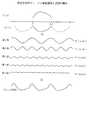
図2は、逆波長特性のフーリエ級数展開と近似的構成を示す。波長特性G(λ)に対する逆波長特性−G(λ)を第n次の項までフーリエ級数展開することにより、−G(λ)は基本周期および基本周期の整数倍の分周期をもつ余弦関数に分解できる。一般に、次数nを大きくすることにより、任意の精度で−G(λ)を近似することができる。
【0011】
波長等化装置制御方法は、(1) 式の第n項を近似するために、
【0012】
【数2】
【0013】
波長等化装置制御方法は、(1) 式の第n項を近似するために、
【0014】
【数3】
【0015】
ここで、実際のマッハツェンダ型フィルタの特性M1(θ)およびファブリペロ型フィルタの特性F1(θ) は、図3に示すように余弦関数から外れているが、係数が十分に小さい場合には、余弦関数のよい近似となる。したがって、フーリエ級数展開の各項を
【0016】
【数4】
【0017】
波長等化装置制御方法は、(1) 式の第n項を近似するために、上記のマッハツェンダ型フィルタとファブリペロ型フィルタを組み合わせ、その係数を
【0018】
【数5】
【0019】
ここで、フーリエ級数展開の各項を
【0020】
【数6】
【0021】
また、マッハツェンダ型フィルタやファブリペロ型フィルタに代えて、ファイバグレーティング等の回折格子を用いても同様に波長等化装置を構成することができる。
【0022】
ところで、ファブリペロ型光フィルタやマッハツェンダ型光フィルタを直列に接続した波長等化装置を実際に構成する際に、現実のフィルタ特性と理想的なフィルタ特性との間にわずかな誤差が生じる場合には、中継数を重ねるにつれて誤差の累積が問題となる。そこで、現実のフィルタ特性の誤差を補正するフィルタの設定法について以下に説明する。
【0023】
(1) 式に示した波長逆特性−G(λ)を変形し、
【0024】
【数7】
【0025】
【数8】
xii=xi
|xij|<<|xi| (i≠n)
である。
【0026】
ここで、各Eiの中で同じ周期の項をまとめると、
【0027】
【数9】
【0028】
【数10】
【0029】
この(10)式を満たすように各フィルタモジュールのフィルタ特性を設定することにより、所定の特性を有する高精度の波長等化装置を構成することができる。請求項1に記載の波長等化装置制御方法は、波長特性の変化に追従して常に平坦な波長特性を実現するための波長等化装置の制御方法である。すなわち、光増幅中継伝送路に所定の間隔で配置される波長等化装置の出力の波長特性を測定し、波長特性測定手段で測定された波長特性に高速フーリエ変換を施し、波長等化装置の透過率および中心波長を決定する解析し、解析手段で得られたデータに従って波長等化装置の各フィルタモジュールの波長特性を制御する。
【0031】
請求項1に記載の波長等化装置において、波長特性G(λ)に対してその逆特性−G(λ)のフーリエ級数展開によって定義される波長特性Q(λ)をもつ波長等化装置(1) による等化波長特性をG2(λ) とすると、
【0032】
【数11】
【0033】
次に、G(λ)に変動が生じてG′(λ)となり、変動前の等化波長特性G2(λ) がG2′(λ) に変化した場合には、その逆特性−G2′(λ) のフーリエ級数展開によって定義される波長等化装置(2) を新たに追加することにより、再び平坦な波長特性が得られる。ここで、波長等化装置(2) の波長特性をQ′(λ)、新たな等化波長特性をG3(λ) とすると、
【0034】
【数12】
【0035】
通常、波長等化装置(1) ,(2) は、以下の式で表される波長特性Q2(λ) をもつ1つの波長等化装置に統合することができる。
【0036】
【数13】
【発明の実施の形態】
(第1の実施形態)
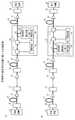
図6は、本発明の波長等化装置の第1の実施形態を示す。
【0038】
波長多重光伝送システムは、図6(a) に示すように、光ファイバ伝送路12と光増幅中継器13を接続した光増幅中継伝送路を介して、送信装置11から受信装置14へ波長多重光信号を伝送する構成である。本発明の波長等化装置15は、この光増幅中継伝送路に所定の間隔で配置され、図1に示したように、直列に接続されたn個のフィルタモジュール1−1〜1−nで構成される。
【0039】
図6(b) に示す波長等化装置15は、各フィルタモジュールが1つまたはN個のマッハツェンダ型フィルタ(MZ)を直列に接続した構成である。図6(c) に示す波長等化装置15は、各フィルタモジュールが1つまたはN個のファブリペロ型フィルタ(FP)を直列に接続した構成である。図6(d) に示す波長等化装置15は、各フィルタモジュールが1つのマッハツェンダ型フィルタ(MZ)と1つのファブリペロ型フィルタ(FP)を直列に接続した構成である。
【0040】
各フィルタモジュールの透過率および中心波長は、波長等化装置15に入力される波長多重光信号の波長特性に高速フーリエ変換を施し、第n項までのフーリエ級数展開の各項の係数を算出してそれぞれ設定される。
【0041】
(第2の実施形態)
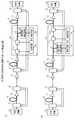
図7は、本発明の波長等化装置の第2の実施形態を示す。本実施形態の波長等化装置16は、波長特性の変化に応じてフィルタ特性を可変させることを特徴とし、(a) はフィードバック構成、(b) はフィードフォワード構成を示す。
【0042】
図において、光分岐器21で伝送に影響ない程度に分岐された光信号は、波長特性測定手段22に入力される。波長特性測定手段22によって測定された時間的な波長特性の情報は、解析手段23に送られる。解析手段23は、波長特性に高速フーリエ変換を施し、フーリエ級数展開の各項の係数から各フィルタモジュールの深さおよび中心波長を求め、制御手段24へ送出する。制御手段24は、得られた情報を元に各フィルタモジュール1−1〜1−nの波長特性(透過率および中心波長)を制御する。
【0043】
(第3の実施形態)
図8は、本発明の波長等化装置の第3の実施形態を示す。本実施形態の特徴は、第2の実施形態で示した波長等化装置16で得られた各フィルタモジュールの制御情報により、その前後に配置される波長等化装置17の各フィルタモジュールの透過率および中心波長を制御するところにある。波長等化装置17は、波長特性が可変のフィルタモジュールを備えるだけで、波長特性の変化に対応する等化処理を行うことができる。
【0044】
ここで、波長特性が可変のフィルタモジュールの具体例について、図9を参照して説明する。図9(a) は、マッハツェンダ型フィルタ31の光路中に屈折率が可変する屈折率変移媒質32−1,32−2を挿入した例を示す。制御手段24の制御により屈折率を可変させる屈折率変移媒質32としては、例えばリチウムナイオベイト(LiNbO3)を用いることができる。
【0045】
図9(b) は、ファブリペロ型フィルタの光路中に利得を制御できる増幅媒体を挿入した例を示す。制御手段24の制御により利得を制御できるファブリペロ型フィルタにおける増幅媒体としては、例えば両端面に反射コーティング33−1,33−2を施した半導体光増幅器34を用いることができる。
【0046】
図9(c) は、利得を制御できる増幅機能を備えた回折格子を用いた例を示す。ここでは、エルビウム添加・ファイバグレーティング35と励起光源36を用い、エルビウム添加・ファイバグレーティング35に入力する励起光パワーを制御手段24により制御する。
【0047】
以上説明したように、本発明の波長等化装置制御方法は、光増幅中継伝送路のある点における波長特性が与えられた場合に、その特性を補償する逆波長特性を効率的に設計することができる。特に、伝送距離が長くなる場合、従来の経験的な波長等化器の設定法では平坦な波長特性を長距離維持することが困難になるので、本発明のような明確な設計法がもたらす効果は大きい。
【0048】
また、本発明の波長等化装置制御方法は、光増幅中継伝送路の波長特性に時間的変化が生じても、各フィルタモジュールの透過率および中心波長を適当に設定することができ、常に平坦な波長特性を実現することができる。
【図面の簡単な説明】
【図1】本発明の波長等化装置の基本構成を示す図。
【図2】逆波長特性のフーリエ級数展開と近似的構成を示す図。
【図3】マッハツェンダ型フィルタとファブリペロ型フィルタの特性を示す図。
【図4】フィルタ特性と余弦関数との誤差とフィルタ数の関係を示す図。
【図5】本発明装置による波長等化誤差とフーリエ級数展開の次数の関係を示す図。
【図6】本発明の波長等化装置の第1の実施形態を示すブロック図。
【図7】本発明の波長等化装置の第2の実施形態を示すブロック図。
【図8】本発明の波長等化装置の第3の実施形態を示すブロック図。
【図9】波長特性が可変のフィルタモジュールの具体例を示す図。
【符号の説明】
1−1〜1−n フィルタモジュール
11 送信装置
12 光ファイバ伝送路
13 光増幅中継器
14 受信装置
15,16,17 波長等化装置
21 光分岐器
22 波長特性測定手段
23 解析手段
24 制御手段
31 マッハツェンダ型フィルタ
32 屈折率変移媒質
33 反射コーティング
34 半導体光増幅器
35 エルビウムドープ・ファイバグレーティング
36 励起光源[0001]
BACKGROUND OF THE INVENTION
The present invention relates to a wavelength-multiplexed optical transmission system that transmits a wavelength-multiplexed optical signal through an optical amplification repeater transmission line that connects an optical fiber transmission line and an optical amplification repeater. The present invention relates to a wavelength equalizer that compensates for deviations in characteristics.
[0002]
[Prior art]
The wavelength division multiplexing optical transmission system has a wavelength characteristic deviation due to the gain characteristic of the optical amplifying repeater. This deviation in wavelength characteristics causes a level difference between the signal channels and causes a decrease in level in a specific signal channel.
[0003]
Conventionally, in order to compensate for the level difference between the signal channels, a method of flattening the gain characteristics of the optical amplifying repeater or an optical equalization filter (for example, a Mach-Zehnder filter or a Fabry-Perot filter) that compensates the wavelength characteristics are appropriate. A method of inserting into an optical fiber transmission line at a proper interval has been studied.
[0004]
[Problems to be solved by the invention]
The characteristics of the conventional optical equalization filter that compensates the wavelength characteristics of the optical amplification repeater transmission line are determined by trial and error, and an efficient design method has not been established.
[0005]
Even if an optical equalization filter corresponding to a certain wavelength characteristic is configured by trial and error, if the wavelength characteristic changes according to changes in the optical signal level, optical amplifier output, etc., the characteristics of the optical equalization filter Could not be followed.
[0006]
The present invention can efficiently design an optical equalization filter corresponding to a given wavelength characteristic, and can always realize a flat wavelength characteristic by following a change in the wavelength characteristic. The purpose is to provide.
[0007]
Thewavelength equalization apparatus control method of the present invention is a wavelength division multiplexing optical transmission system that transmits a wavelength multiplexed optical signal from a transmission apparatus to a reception apparatus via an optical amplification repeater transmission path in which an optical fiber transmission path and an optical amplification repeater are connected. ofa wavelength equalizer to compensate for the deviation in wavelength characteristic, the plurality of n approximating each the sections the inverse characteristic of the wavelength characteristics and Fourier series expansion for the base period a predetermined wavelength range including a transmission band Wavelength equalizing means in which filter modules are connected in series; wavelength characteristic measuring means for measuring wavelength characteristics of input or output of the wavelength equalizing means arranged at predetermined intervals on the optical amplification repeater transmission line; and the wavelength Analyzing means for determining the transmittance and center wavelength of the wavelength equalizing means based on the wavelength characteristics measured by the characteristic measuring means, and the wave of each filter module according to the data obtained by the analyzing means.In order to perform feedback control in a wavelength equalization apparatus Ru and control means for controlling the characteristic wavelength of each filter module to cancel the extra high order expansion terms of the Fourier series expansion terms of wavelength characteristics of each filter module Ifthe wavelength characteristic measuredby the wavelength characteristic measuring meanschanges, the inverse wavelength characteristic at the output after the fluctuation is calculated, and the inverse characteristic of the calculated wavelength characteristic is subjected to fast Fourier transform, The wavelength characteristic of each filter module is controlled by adding the Fourier series expansion term and the current wavelength characteristic of each filter module and settingthe wavelength characteristicobtained as a result of the addition as a new approximation target.
[0008]
When the wavelength characteristic G (λ) [dB] of a certain section of the optical amplification repeater transmission path is given, the inverse wavelength characteristic −G (λ) is obtained by Fourier series expansion.
[0009]
[Expression 1]
[0010]
FIG. 2 shows a Fourier series expansion of the inverse wavelength characteristic and an approximate configuration. -G (λ) is a cosine function having a fundamental period and a fractional period that is an integral multiple of the fundamental period by expanding the inverse wavelength characteristic -G (λ) with respect to the wavelength characteristic G (λ) to the n-th order Fourier series. Can be disassembled. In general, by increasing the order n, −G (λ) can be approximated with arbitrary accuracy.
[0011]
In order to approximate the n-th term of the equation (1), thewavelength equalizer control method
[0012]
[Expression 2]
[0013]
In order to approximate the n-th term of the equation (1), thewavelength equalizer control method
[0014]
[Equation 3]
[0015]
Here, the actual characteristic M1 (θ) of the Mach-Zehnder filter and the characteristic F1 (θ) of the Fabry-Perot filter deviate from the cosine function as shown in FIG. 3, but when the coefficient is sufficiently small, This is a good approximation of the cosine function. Therefore, each term of the Fourier series expansion is
[Expression 4]
[0017]
The wavelength equalizer control method combines the above Mach-Zehnder type filter and Fabry-Perot type filter in order to approximate the n-th term of the equation (1), and sets its coefficient to
[Equation 5]
[0019]
Where each term of the Fourier series expansion is
[Formula 6]
[0021]
In place of the Mach-Zehnder filter or Fabry-Perot filter,Ru can configure the wavelength equalizer similarly be used a diffraction grating such as a fibergrating.
[0022]
By the way, when actually configuringa wavelength equalization apparatus in which aFabry-Perot type optical filter or a Mach-Zehnder type optical filter is connected in series, there is a slight error between the actual filter characteristic and the ideal filter characteristic. As the number of relays increases, accumulation of errors becomes a problem. Therefore, a filter setting method for correcting an error in actual filter characteristics will be described below.
[0023]
The inverse wavelength characteristic -G (λ) shown in equation (1) is modified,
[0024]
[Expression 7]
[0025]
[Equation 8]
xii = xi
| Xij | << | xi | (i ≠ n)
It is.
[0026]
Here, when the terms of the same period are grouped in each Ei ,
[0027]
[Equation 9]
[0028]
[Expression 10]
[0029]
By setting the filter characteristics of each filter module so as to satisfy the equation (10), it is possible to configure a highly accurate wavelength equalizer having a predetermined characteristic. The wavelength equalizercontrol method according to
[0031]
2. The wavelength equalizer accordingto
[0032]
## EQU11 ##
[0033]
Next, when G (λ) fluctuates to G ′ (λ) and the equalized wavelength characteristic G2 (λ) before the fluctuation changes to G2 ′ (λ), the inverse characteristic −G By adding a new wavelength equalizer (2) defined by the Fourier series expansion of2 ′ (λ), a flat wavelength characteristic can be obtained again. Here, when the wavelength characteristic of the wavelength equalizer (2) is Q ′ (λ) and the new equalized wavelength characteristic is G3 (λ),
[0034]
[Expression 12]
[0035]
Usually, the wavelength equalizers (1) and (2) can be integrated into one wavelength equalizer having a wavelength characteristic Q2 (λ) expressed by the following equation.
[0036]
[Formula 13]
DETAILED DESCRIPTION OF THE INVENTION
(First embodiment)
FIG. 6 shows a first embodiment of the wavelength equalizer of the present invention.
[0038]
As shown in FIG. 6 (a), the wavelength division multiplexing optical transmission system is wavelength multiplexed from the
[0039]
The
[0040]
The transmittance and the center wavelength of each filter module are obtained by performing a fast Fourier transform on the wavelength characteristics of the wavelength multiplexed optical signal input to the
[0041]
(Second Embodiment)
FIG. 7 shows a second embodiment of the wavelength equalizer of the present invention. The
[0042]
In the figure, the optical signal branched to such an extent that the optical branching
[0043]
(Third embodiment)
FIG. 8 shows a third embodiment of the wavelength equalizer of the present invention. The feature of this embodiment is that the transmittance of each filter module of the
[0044]
Here, a specific example of a filter module having a variable wavelength characteristic will be described with reference to FIG. FIG. 9Ashows an example in which refractive index changing media 32-1 and 32-2 having a variable refractive index are inserted in the optical path of the Mach-
[0045]
FIG. 9Bshows an example in whichan amplification medium capable of controlling the gain is inserted in the optical path of the Fabry-Perot filter. As an amplification medium in a Fabry-Perot filter whose gain can be controlled by the control means 24, for example, a semiconductor
[0046]
FIG. 9 (c)shows an example using a diffraction grating having an amplification function capable of controlling the gain. Here, the erbium-added / fiber grating 35 and the
[0047]
As described above, thewavelength equalizer control method according to the present invention efficiently designs the reverse wavelength characteristic that compensates for a given wavelength characteristic at a certain point of the optical amplification repeater transmission line. Can do. In particular, when the transmission distance becomes long, it becomes difficult to maintain a flat wavelength characteristic for a long distance by the conventional empirical wavelength equalizer setting method, and thus the effect of a clear design method such as the present invention is brought about. Is big.
[0048]
Further, thewavelength equalizer control method of the present invention can set the transmittance and the center wavelength of each filter module appropriately even if the wavelength characteristic of the optical amplification repeater transmission line changes with time, and is always flat. Wavelength characteristics can be realized.
[Brief description of the drawings]
FIG. 1 is a diagram showing a basic configuration of a wavelength equalizer according to the present invention.
FIG. 2 is a diagram showing a Fourier series expansion of an inverse wavelength characteristic and an approximate configuration.
FIG. 3 is a diagram illustrating characteristics of a Mach-Zehnder filter and a Fabry-Perot filter.
FIG. 4 is a diagram illustrating a relationship between an error between a filter characteristic and a cosine function and the number of filters.
FIG. 5 is a diagram showing a relationship between a wavelength equalization error and an order of Fourier series expansion by the apparatus of the present invention.
FIG. 6 is a block diagram showing a first embodiment of a wavelength equalizer according to the present invention.
FIG. 7 is a block diagram showing a second embodiment of the wavelength equalizer of the present invention.
FIG. 8 is a block diagram showing a third embodiment of the wavelength equalizer of the present invention.
FIG. 9 is a diagram illustrating a specific example of a filter module having a variable wavelength characteristic.
[Explanation of symbols]
1-1 to 1-
Claims (1)
Translated fromJapanese前記各フィルタモジュールの波長特性のフーリエ級数展開項の余分な高次展開項を打ち消しあうように各フィルタモジュールの波長特性を設定する第一の過程と、
前記波長特性測定手段で測定された波長特性に変動が生じた場合、変動後の出力における逆波長特性を算出する第二の過程と、
算出された前記波長特性の逆特性に高速フーリエ変換を施し、各フーリエ級数展開項と前記各フィルタモジュールの現波長特性と足し合わせる第三の過程と、
足し合わした結果得られた波長特性を新たな近似目標として、前記各フィルタモジュールの波長特性を制御する第四の過程とを実行する
ことを特徴とする波長等化装置制御方法。Wavelength equalization that compensates for wavelength characteristic deviation in wavelength division multiplexing optical transmission systems that transmit wavelength division multiplexed optical signals from a transmitter to a receiver via an optical amplification repeater that connects an optical fiber transmission line and an optical amplification repeateran apparatus, a predetermined plurality of n wavelengths equalization means for the filter module connected in series to each approximating the sections were Fourier series expansion of the inverse characteristic of the wavelength characteristics of the wavelength range as a basic period including the transmission bandwidth A wavelength characteristic measuring means for measuring the wavelength characteristics of the input or output of the wavelength equalizing means arranged at predetermined intervals on the optical amplification repeater transmission line, and a wavelength characteristic measured by the wavelength characteristic measuring means. analyzing means for determining the transmittance and the center wavelength of the wavelength equalizing means, and control means for controlling the wavelength characteristic of each filter module in accordance with the data obtained by said analyzing means includes theA wavelength equalizer control method which performs feedback control in a wavelength equalizer,
Before Symbola first step of setting a wavelength characteristic of each filter module to cancel the extra high order expansion terms of the Fourier series expansion terms of wavelength characteristics of each filtermodule,
Before SLwhen the variation in the measured wavelength characteristics in the wavelength characteristic measurement unitoccurs, a second step of calculating the inverse wavelength characteristics in the output after change,
Performing fast Fourier transform on the inverse characteristic ofsaid calculated wavelength characteristic,and a third step Ru alignment plus the respective Fourier series expansion terms wherein the current wavelength characteristic of each filtermodule,
A wavelength equalizer control methodcomprising: performing a fourth step of controlling the wavelength characteristics of each of the filter modules, using the wavelength characteristicsobtained as a result of the addition as a new approximation target.
Priority Applications (1)
| Application Number | Priority Date | Filing Date | Title |
|---|---|---|---|
| JP16203299AJP3745560B2 (en) | 1998-11-05 | 1999-06-09 | Wavelength equalizer control method |
Applications Claiming Priority (3)
| Application Number | Priority Date | Filing Date | Title |
|---|---|---|---|
| JP31514498 | 1998-11-05 | ||
| JP10-315144 | 1998-11-05 | ||
| JP16203299AJP3745560B2 (en) | 1998-11-05 | 1999-06-09 | Wavelength equalizer control method |
Publications (2)
| Publication Number | Publication Date |
|---|---|
| JP2000199880A JP2000199880A (en) | 2000-07-18 |
| JP3745560B2true JP3745560B2 (en) | 2006-02-15 |
Family
ID=26487959
Family Applications (1)
| Application Number | Title | Priority Date | Filing Date |
|---|---|---|---|
| JP16203299AExpired - Fee RelatedJP3745560B2 (en) | 1998-11-05 | 1999-06-09 | Wavelength equalizer control method |
Country Status (1)
| Country | Link |
|---|---|
| JP (1) | JP3745560B2 (en) |
Families Citing this family (9)
| Publication number | Priority date | Publication date | Assignee | Title |
|---|---|---|---|---|
| JP2004096653A (en) | 2002-09-04 | 2004-03-25 | Nec Corp | Optical transmitter and optical modulation method to be used therefor |
| JP3974018B2 (en) | 2002-11-13 | 2007-09-12 | 富士通株式会社 | Variable optical filter, optical transmission system using the same, and variable optical filter control method |
| JP4409320B2 (en) | 2004-03-19 | 2010-02-03 | 日本航空電子工業株式会社 | Variable optical gain equalizer and optical gain equalizer |
| US7647083B2 (en) | 2005-03-01 | 2010-01-12 | Masimo Laboratories, Inc. | Multiple wavelength sensor equalization |
| US8265723B1 (en) | 2006-10-12 | 2012-09-11 | Cercacor Laboratories, Inc. | Oximeter probe off indicator defining probe off space |
| US8374665B2 (en) | 2007-04-21 | 2013-02-12 | Cercacor Laboratories, Inc. | Tissue profile wellness monitor |
| US9839381B1 (en) | 2009-11-24 | 2017-12-12 | Cercacor Laboratories, Inc. | Physiological measurement system with automatic wavelength adjustment |
| WO2011069122A1 (en) | 2009-12-04 | 2011-06-09 | Masimo Corporation | Calibration for multi-stage physiological monitors |
| CN110277182B (en)* | 2019-06-18 | 2021-05-18 | 西南科技大学 | Preparation method of corrosive self-brittle radioactive detergent for iron-based material surface |
Family Cites Families (8)
| Publication number | Priority date | Publication date | Assignee | Title |
|---|---|---|---|---|
| JPH06276154A (en)* | 1993-03-19 | 1994-09-30 | Nippon Telegr & Teleph Corp <Ntt> | Optical gain equalization circuit |
| JPH0918416A (en)* | 1995-06-28 | 1997-01-17 | Hitachi Ltd | Optical amplifier |
| JP3556379B2 (en)* | 1996-03-07 | 2004-08-18 | 富士通株式会社 | Optical transmission system |
| JPH09289349A (en)* | 1996-04-23 | 1997-11-04 | Nec Corp | Optical equalizer, optical amplifier using it and wavelength-multiple optical transmitter |
| JP3408378B2 (en)* | 1996-07-03 | 2003-05-19 | 日本電気株式会社 | Optical repeater amplifier |
| JP3769359B2 (en)* | 1997-08-11 | 2006-04-26 | 富士通株式会社 | Wavelength multiplexed optical amplification transmission system and optical amplifier |
| JPH1187812A (en)* | 1997-09-12 | 1999-03-30 | Fujitsu Ltd | Gain equalizer and optical transmission system provided with the gain equalizer |
| JP2000082858A (en)* | 1998-07-07 | 2000-03-21 | Furukawa Electric Co Ltd:The | Optical gain equalizer, optical amplifier and wavelength division multiplex transmission device using the same |
- 1999
- 1999-06-09JPJP16203299Apatent/JP3745560B2/ennot_activeExpired - Fee Related
Also Published As
| Publication number | Publication date |
|---|---|
| JP2000199880A (en) | 2000-07-18 |
Similar Documents
| Publication | Publication Date | Title |
|---|---|---|
| US6411417B1 (en) | Optical equalizer | |
| US6356684B1 (en) | Adjustable optical fiber grating dispersion compensators | |
| US5636301A (en) | Optical waveguide amplifiers | |
| JP3803000B2 (en) | Method for monitoring optical power deviation between wavelengths, and optical equalizer and optical amplifier using the same | |
| US6545799B1 (en) | Method and apparatus for optical system link control | |
| US7013063B2 (en) | System for higher-order dispersion compensation including phase modulation | |
| JP3745560B2 (en) | Wavelength equalizer control method | |
| EP1013021A1 (en) | Dynamic optical amplifier | |
| KR20010041551A (en) | an optical device for dispersion compensation | |
| US6427040B1 (en) | Optical waveguide gratings device with adjustable optical space profile | |
| US6421167B1 (en) | Multiple function bandwidth management systems | |
| US11290184B2 (en) | Switchable dispersion compensating module | |
| US5887091A (en) | Bidirectional optical amplifier having flat gain | |
| JP2004343692A (en) | Method and apparatus for monitoring channel performance in Dense Wavelength Division Multiplexing (DWDM) optical networks | |
| US6859622B1 (en) | Predictive optimization of wavelength division multiplexed systems | |
| US5852700A (en) | Method and device for the generation of ultrashort optical pulses | |
| US6842561B2 (en) | Optical performance monitoring scheme | |
| CN1784849B (en) | Method for pre-emphasis of an optical multiplex signal | |
| US20030152320A1 (en) | System for higher-order dispersion compensation | |
| CN101180815B (en) | System for reducing crosstalk in optical wavelength converters | |
| US7016567B2 (en) | System for higher-order dispersion compensation including a delay line | |
| US7206124B2 (en) | Gain-providing optical power equalizer | |
| US20040208577A1 (en) | Methods for in-service wavelength upgrade and system performance optimization in WDM optical networks | |
| US6577788B1 (en) | Gain equalization system and method | |
| JPH09289348A (en) | Optical amplifier gain control apparatus and method |
Legal Events
| Date | Code | Title | Description |
|---|---|---|---|
| A977 | Report on retrieval | Free format text:JAPANESE INTERMEDIATE CODE: A971007 Effective date:20040401 | |
| A131 | Notification of reasons for refusal | Free format text:JAPANESE INTERMEDIATE CODE: A131 Effective date:20040706 | |
| A521 | Written amendment | Free format text:JAPANESE INTERMEDIATE CODE: A523 Effective date:20040903 | |
| A02 | Decision of refusal | Free format text:JAPANESE INTERMEDIATE CODE: A02 Effective date:20050628 | |
| A521 | Written amendment | Free format text:JAPANESE INTERMEDIATE CODE: A523 Effective date:20050826 | |
| A911 | Transfer of reconsideration by examiner before appeal (zenchi) | Free format text:JAPANESE INTERMEDIATE CODE: A911 Effective date:20050901 | |
| TRDD | Decision of grant or rejection written | ||
| A01 | Written decision to grant a patent or to grant a registration (utility model) | Free format text:JAPANESE INTERMEDIATE CODE: A01 Effective date:20051101 | |
| A61 | First payment of annual fees (during grant procedure) | Free format text:JAPANESE INTERMEDIATE CODE: A61 Effective date:20051117 | |
| FPAY | Renewal fee payment (event date is renewal date of database) | Free format text:PAYMENT UNTIL: 20091202 Year of fee payment:4 | |
| FPAY | Renewal fee payment (event date is renewal date of database) | Free format text:PAYMENT UNTIL: 20101202 Year of fee payment:5 | |
| FPAY | Renewal fee payment (event date is renewal date of database) | Free format text:PAYMENT UNTIL: 20101202 Year of fee payment:5 | |
| FPAY | Renewal fee payment (event date is renewal date of database) | Free format text:PAYMENT UNTIL: 20111202 Year of fee payment:6 | |
| FPAY | Renewal fee payment (event date is renewal date of database) | Free format text:PAYMENT UNTIL: 20111202 Year of fee payment:6 | |
| FPAY | Renewal fee payment (event date is renewal date of database) | Free format text:PAYMENT UNTIL: 20121202 Year of fee payment:7 | |
| FPAY | Renewal fee payment (event date is renewal date of database) | Free format text:PAYMENT UNTIL: 20121202 Year of fee payment:7 | |
| FPAY | Renewal fee payment (event date is renewal date of database) | Free format text:PAYMENT UNTIL: 20131202 Year of fee payment:8 | |
| S531 | Written request for registration of change of domicile | Free format text:JAPANESE INTERMEDIATE CODE: R313531 | |
| R350 | Written notification of registration of transfer | Free format text:JAPANESE INTERMEDIATE CODE: R350 | |
| LAPS | Cancellation because of no payment of annual fees |