JP3744785B2 - Composite reception delivery device - Google Patents
Composite reception delivery deviceDownload PDFInfo
- Publication number
- JP3744785B2 JP3744785B2JP2000317767AJP2000317767AJP3744785B2JP 3744785 B2JP3744785 B2JP 3744785B2JP 2000317767 AJP2000317767 AJP 2000317767AJP 2000317767 AJP2000317767 AJP 2000317767AJP 3744785 B2JP3744785 B2JP 3744785B2
- Authority
- JP
- Japan
- Prior art keywords
- signal
- receiver
- connection
- broadcast
- digital
- Prior art date
- Legal status (The legal status is an assumption and is not a legal conclusion. Google has not performed a legal analysis and makes no representation as to the accuracy of the status listed.)
- Expired - Fee Related
Links
Images


Classifications
- H—ELECTRICITY
- H04—ELECTRIC COMMUNICATION TECHNIQUE
- H04N—PICTORIAL COMMUNICATION, e.g. TELEVISION
- H04N21/00—Selective content distribution, e.g. interactive television or video on demand [VOD]
- H04N21/40—Client devices specifically adapted for the reception of or interaction with content, e.g. set-top-box [STB]; Operations thereof
- H04N21/41—Structure of client; Structure of client peripherals
- H04N21/426—Internal components of the client ; Characteristics thereof
- H04N21/42607—Internal components of the client ; Characteristics thereof for processing the incoming bitstream
- H04N21/4263—Internal components of the client ; Characteristics thereof for processing the incoming bitstream involving specific tuning arrangements, e.g. two tuners
- H—ELECTRICITY
- H04—ELECTRIC COMMUNICATION TECHNIQUE
- H04N—PICTORIAL COMMUNICATION, e.g. TELEVISION
- H04N21/00—Selective content distribution, e.g. interactive television or video on demand [VOD]
- H04N21/40—Client devices specifically adapted for the reception of or interaction with content, e.g. set-top-box [STB]; Operations thereof
- H04N21/45—Management operations performed by the client for facilitating the reception of or the interaction with the content or administrating data related to the end-user or to the client device itself, e.g. learning user preferences for recommending movies, resolving scheduling conflicts
- H04N21/462—Content or additional data management, e.g. creating a master electronic program guide from data received from the Internet and a Head-end, controlling the complexity of a video stream by scaling the resolution or bit-rate based on the client capabilities
- H04N21/4622—Retrieving content or additional data from different sources, e.g. from a broadcast channel and the Internet
Landscapes
- Engineering & Computer Science (AREA)
- Multimedia (AREA)
- Signal Processing (AREA)
- Databases & Information Systems (AREA)
- Two-Way Televisions, Distribution Of Moving Picture Or The Like (AREA)
- Circuits Of Receivers In General (AREA)
- Details Of Television Systems (AREA)
Description
Translated fromJapanese【0001】
【発明の属する技術分野】
本発明は、複数の放送を受信し配信できる複合受信配信装置に関し、特に、各放送事業者に固有の放送番組または放送データのキャリア信号を受信し、共通な信号形式のベースバンド信号に変換して出力する受信器と、一つの受信配信装置に複数の前記受信器を収納することによって、複数の放送事業者の放送信号を受信することができ、かつ、複数の任意の表示装置に対して受信信号を配信することができる複合受信配信装置に関する。
【0002】
【従来の技術】
従来の放送形態としては、地上波アナログ放送、BS(Broadcasting Satellite:放送衛星)アナログ放送、アナログCATV放送、CS(Communication Satellite:通信衛星)デジタル放送があり、これまでは、アナログ放送主体の放送サービスがなされてきた。近年のデジタル技術の進展により、放送形態においてもデジタル化が進み、CSデジタル放送に限らず、上述したアナログ放送は、デジタル放送(BSデジタル放送、デジタルCATV放送、地上波デジタル放送)に移行しようとしており、BSアナログ放送と地上波アナログ放送とはある移行期間を経て放送が打ち切られようとしている。
【0003】
デジタル放送では、映像信号や音声信号が例えばMPEG−2(Moving Picture Experts Group−2)方式によりデジタル圧縮されて送信され、既存のアナログ放送に比べて、高品質の信号を伝送することが可能であると共に、周波数利用効率が向上され、多チャンネル化が図れる。また、デジタル放送では、映像や音声のみならず、データ放送等のサービスを行うことも可能である。
【0004】
現在、既にCSデジタル放送サービスが開始されている。CSデジタル放送では、スポーツ、映画、音楽、ニュース等のコンテンツを放送する多数のチャンネルが用意されており、1つの衛星のチャンネル数としては数100チャンネルが確保されている。
【0005】
更に、今後、BSデジタル放送、デジタルCATV放送、地上波デジタル放送のサービスが順次開始されようとしている。また、いくつかのCSデジタル放送用の衛星が打ち上げられ、いくつかのCSデジタル放送のサービスも開始されんとしている。而して、かかる各種のデジタル放送サービスにおいては、より興味深い各種の番組が提供されるチャンネルを用意しようと準備が進められている状況にある。
【0006】
各種のデジタル放送のサービスが登場してくると、現在のアナログ放送サービスに加えて複数のデジタル放送のサービスに加入して、種々の放送サービスを楽しみたいと考える利用者が増えてくる。
【0007】
そして、これらのデジタル放送を受信する場合、それぞれのデジタル放送に固有のデジタル映像信号及びデジタル音声信号をデコードするための専用の放送受信装置STB(Set Top Box、以下、STBと記す)が必要である。
【0008】
しかしながら、基本的には、かかる専用STBは、テレビジョン受信機等の表示装置に対して1対1に配設する必要があり、専用STBと接続されている表示装置でしかデジタル放送を視聴することができない。
【0009】
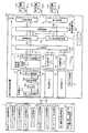
以下、図6に示す従来の宅内の受信配線設備の系統構成図を参照しながら、従来技術を適用した場合においてデジタル放送の受配信を行なう一例について説明する。図6において、550は、複数の放送信号を受信し、複数の表示装置にそれぞれの受信信号を配信する宅内配線システムを示している。11は放送衛星を使ってデジタル番組映像の提供サービスを行なうBSデジタル放送事業者、12は第1の通信衛星を使ってデジタル番組映像の提供サービスを行なうCSデジタル放送事業者#1、13は第2の通信衛星を使ってデジタル番組映像の提供サービスを行なうCSデジタル放送事業者#2、14は一般の加入契約者に対して同軸ケーブルまたは光ファイバケーブルの屋外有線ケーブルを介してアナログ番組映像あるいはデジタル番組映像の提供サービスを行なうCATV放送事業者、15は地上波を使ってデジタル番組映像の提供サービスを行なう地上波デジタル放送事業者、16は放送衛星を使ってアナログ番組映像の提供サービスを行なうBSアナログ放送事業者、17は地上波を使ってアナログ番組映像の提供サービスを行なう地上波アナログ放送事業者である。
【0010】
11aはBSデジタル放送及びBSアナログ放送を受信用のBSアンテナ部、12aは第1の通信衛星からの電波を受信する第1のCSデジタル放送受信用アンテナ部、13aは第2の通信衛星からの電波を受信する第2のCSデジタル放送受信用アンテナ部、15aは地上波デジタル放送受信用アンテナ部、17aは地上波アナログ受信用アンテナ部である。
【0011】
500はBSアンテナ部11aで受信した信号並びに地上波アナログ放送受信用アンテナ部17aで受信した信号を混合して同軸ケーブル510に送出する混合器、501は同軸ケーブル510を介して伝送される信号を同軸ケーブル511aと511bと511cとを介してそれぞれ部屋aと部屋bと部屋cとに分配する分配器、502は第1のCS放送受信用アンテナ部12aで受信した信号を同軸ケーブル512aと512bとを介してそれぞれ部屋aと部屋bとに分配する分配器、503は第2のCS放送受信用アンテナ部13aで受信した信号を同軸ケーブル513aと513cとを介してそれぞれ部屋aと部屋cとに分配する分配器、504はCATVネットワークの屋外有線ケーブル14aを介して伝送される信号を同軸ケーブル514aと514bとを介してそれぞれ部屋aと部屋bに分配する分配器、505は地上波デジタル放送受信用アンテナ部15aで受信した信号を同軸ケーブル515aと515bとを介してそれぞれ部屋aと部屋bとに分配する分配器である。
【0012】
411a並びに411cはそれぞれ部屋a並びに部屋cに配設され、アンテナ部11aから受信したBSデジタル放送のスクランブルを解除し、BSデジタル放送の番組チャンネル選択制御を行なうBSデジタル放送受信装置(BSデジタル用STB)、412a並びに412bはそれぞれ部屋a並びに部屋bに配設され、アンテナ部12aから受信した第1のCSデジタル放送のスクランブルを解除し、CSデジタル放送の番組チャンネル選択制御を行なう第1のCSデジタル放送受信装置(CS#1用STB)、413aは部屋aに配設され、アンテナ部13aから受信した第2のCSデジタル放送のスクランブルを解除し、CSデジタル放送の番組チャンネル選択制御を行なう第2のCSデジタル放送受信装置(CS#2用STB)、414a並びに414bはそれぞれ部屋a並びに部屋bに配設され、CATVネットワークの屋外有線ケーブル14aを経由して受信した有線放送のスクランブルを解除し、CATV有線放送の番組チャンネル選択制御を行なうCATV受信装置(CATV用STB)、415a並びに415bはそれぞれ部屋a並びに部屋bに配設され、アンテナ部15aから受信した地上波デジタル放送の番組チャンネル選択制御を行なう地上波デジタル放送受信装置(地上波デジタル用STB)である。
【0013】
521a並びに521cはそれぞれBSデジタル用STB411a並びに411cにてスクランブル解除されたBS放送番組の映像出力信号をそれぞれ部屋a並びに部屋cに配設されているAVセレクタ手段420a並びに420cに外部入力するための接続ケーブル、522a及び522bはそれぞれCS#1用STB412a並びに412bにてスクランブル解除されたCS放送番組の映像出力信号をそれぞれ部屋a並びに部屋bに配設されているAVセレクタ手段420a並びに420bに外部入力するための接続ケーブル、523aはCS#2用STB413aにてスクランブル解除されたCS放送番組の映像出力信号を部屋aに配設されているAVセレクタ手段420aに外部入力する為の接続ケーブル、524a並びに524bはそれぞれCATV用STB414a並びに414bにてスクランブル解除されたCATV番組の映像出力信号をそれぞれ部屋a並びに部屋bに配設されているAVセレクタ手段420a並びに420bに外部入力するための接続ケーブル、525a並びに525bはそれぞれ地上波デジタル用STB415a並びに415bから出力される番組の映像出力信号をそれぞれ部屋a並びに部屋bに配設されているAVセレクタ手段420a並びに420bに外部入力するための接続ケーブルである。
【0014】
420aと420b並びに420cは複数の映像信号の外部入力から選択指示された入力信号にそれぞれ部屋aと部屋b並びに部屋cに配設されている表示装置であるテレビジョン受信機430aと430b並びに430cの表示を切り替えるAVセレクタ手段であり、430aはAVセレクタ手段420aを有するテレビジョン受信機#1、430bはAVセレクタ手段420bとBSアナログ受信手段416bとを有するテレビジョン受信機#2、430cはAVセレクタ手段420cを有するテレビジョン受信機#3である。
【0015】
以上のように構成される図6に示す宅内配線システム550を構築するに際し、以下、その利用者が現在のアナログ放送の他に複数のデジタル放送を新たに受信するために用意する必要がある各STBと敷設する必要がある接続ケーブルなどの構築手順及び部屋a乃至dにおける放送サービスの享受状況について説明する。
【0016】
利用者は、第1の手順として、現在のアナログ放送に加えて複数のデジタル放送のサービスを視聴するために、個々の放送サービス提供事業者(放送事業者)が配信する放送信号を受信する複数のアンテナあるいは複数の屋外専用有線ケーブルを敷設する。
【0017】
第2の手順として、利用者はそれぞれ個々の放送サービスを視聴する視聴場所(部屋)を予め決め、ある特定の放送サービスを該視聴場所で視聴できるようにするために、もし、複数の視聴場所で該特定放送サービスを視聴する場合には、各放送サービス毎に敷設した前記アンテナ等に接続された同軸ケーブルに更に分配器を接続して、該分配器を介して複数の前記視聴場所にそれぞれ室内配線用の同軸ケーブルを配線する。
【0018】
第3の手順として、利用者は個々の放送事業者が指定する専用のSTBを購入或いはレンタルする。このとき、利用者が複数の視聴場所で同時にある特定の放送事業者の放送を視聴したい場合は、各放送事業者が指定する専用のSTBを複数の視聴場所毎に複数個用意する必要がある。
【0019】
第4の手順として、利用者は専用の前記STBを、それぞれの対応する放送事業者用のアンテナと接続されている室内配線用同軸ケーブルに対して接続し、更に、専用の該STBとテレビジョン受信機などの表示装置とを接続ケーブルにより接続する。
【0020】
以上、第1乃至第4の構築手順を経ることにより、利用者は、各視聴場所において放送事業者が無償で配信する放送信号を受信し、番組映像などのサービスを表示装置に映し出すことができる。
【0021】
一方、放送事業者が提供する放送サービスの中には有料の放送番組も含まれており、かかる有料の放送を受信する場合には、いわゆる限定受信方式が採用されている。従って、利用者が該限定受信方式の放送を視聴するためには、予め所定の加入契約を行うことが必要である。
【0022】
即ち、第5の手順として、利用者は限定受信方式の放送を視聴するために放送事業者と所定の加入契約を結ぶことになる。一般に、かかる加入契約の情報を管理する手段としてICカードが用いられている。該ICカードは購入或いはレンタルした各放送事業者に対応する専用STBに装着されて用いられるようになっており、該専用STBには該ICカードを読み書きすることができるICカードドライブが装備されている。
【0023】
放送事業者は、各利用者に加入契約内容に沿った番組を提供するべく、放送番組の他に、個別情報(契約情報、個人宛メッセージ等)や番組表などの番組情報をも個々の各利用者に送出する。各利用者は各放送事業者に対応する専用STBを使用して、前記個別情報や前記番組情報を受信して、専用STBのICカードドライブに挿入されているICカードに記憶する。また、専用STBに入力されてくる有料の放送番組に関する受信信号に関しては、契約情報やスクランブルを解除する鍵を記憶したICカードの内容がICカードドライブを介して読み出されて参照されることにより、スクランブル処理された受信信号がデコードされ、有料の放送番組を表示装置で視聴することができる。
【0024】
以上のごとき手順を踏まえて構築された図6に示す宅内配線システム550においては、利用者は、部屋aでは、BSデジタル放送、第1のCSデジタル放送、第2のCSデジタル放送、CATV放送、地上波デジタル放送、地上波アナログ放送の6種類の放送サービスを享受することができる。
【0025】
部屋bでは、第1のCSデジタル放送、CATV放送、地上波デジタル放送、BSアナログ放送、地上波アナログ放送の5種類の放送サービスを享受することができる。
【0026】
部屋cでは、BSデジタル放送、地上波アナログ放送の2種類の放送サービスを享受することができる。
【0027】
部屋dでは、0種類の放送サービスを享受することができる。
【0028】
【発明が解決しようとする課題】
しかしながら、上述のような宅内配線システムの構成や構築手順においては、利用者が宅内の任意の場所である特定の放送事業者の放送サービスを享受しようとする場合、以下のような課題を有している。
課題(1)として、利用者は、上述の第2の手順に示すように、ある特定の放送事業者の放送サービスを視聴せんとする場合、予め該放送サービスを視聴する視聴場所(部屋)を決めて、該放送サービスの信号を受信するために敷設したアンテナに接続された同軸ケーブルを該視聴場所まで敷設して、該放送サービス用の専用STBに接続して、更に、接続ケーブルを介して該専用STBをテレビジョン受信機に接続しなければ前記放送サービスを享受することができない。ここで、複数の視聴場所で視聴したい場合は、アンテナに接続された同軸ケーブルをまず分配器に接続し、更に、該分配器から複数の各視聴場所までそれぞれ同軸ケーブルを敷設し、該同軸ケーブル毎に前記放送サービス用の専用STBを配設しなければならない。
【0029】
すなわち、利用者がある特定の放送サービスを複数の視聴場所で視聴できる環境を整えようとする場合、特定の該放送サービス受信用アンテナに接続された分配器より分配された同軸ケーブルを希望する複数の視聴場所にまでそれぞれ個別に引き込む作業が必要となる。更に、かかる引込み作業を複数の放送事業者の放送サービス毎にそれぞれ行なう必要がある。
【0030】
課題(2)として、利用者は、上述の第3の手順に示すように、複数の視聴場所で同時にある特定の放送事業者の放送サービスを視聴する場合、放送事業者が指定する専用のSTBを各視聴場所毎に複数個購入あるいはレンタルしなければならない。
【0031】
すなわち、利用者がある特定の放送事業者の放送サービスを任意の複数の場所で同時に視聴できる環境を整えようとする場合、課題(1)の問題を解決したうえで、更に、複数の専用STBを購入あるいはレンタルする必要がある。
【0032】
課題(3)として、利用者が複数の放送事業者の放送サービスを受けようとする場合、それぞれに対応する専用のSTBを購入あるいはレンタルする必要があるが、それぞれのSTBの大きさが不統一であるためにSTBの配置場所に関する利用者の配慮が煩雑となる。
【0033】
本発明は以上のごとき課題に鑑みてなされたものであり、本発明の第1の目的は、利用者がある特定の放送事業者の放送サービスを任意の場所で視聴できる環境を整えようとする場合、特定の該放送サービスの信号を受信するためのアンテナと該信号をデコードすることができる放送受信装置STB(以下、本発明においては、従来のSTBとの用語上の混乱を防ぐため、受信器と記す)との間のケーブル接続を行なう配線作業をするだけで、該受信器から各表示装置までのケーブル配線を該放送サービス毎にしなくても任意の場所で視聴できる環境を構築することができる複合受信配信装置を提供することである。
【0034】
本発明の第2の目的は、利用者がある特定の放送事業者の放送サービスを複数の視聴場所で同時に視聴できる環境を整えようとする場合、該放送事業者が指定する専用の受信器を1個のみ購入あるいはレンタルするだけで任意の複数の視聴場所で同時に視聴できる環境を構築することができる複合受信配信装置を提供することである。
【0035】
本発明の第3の目的は、利用者が複数の放送事業者の放送サービスを享受しようとした場合でも、各放送事業者毎に必要となる専用の各受信器の外形形状や外形寸法に囚われる必要がない同一構造の受信器のみを収納できる複合受信配信装置を提供することである。
【0036】
【課題を解決するための手段】
本発明は、上記目的を達成するために、宅内に設置されて、一つまたは複数の固有の信号形式に基づいて配信される放送番組または放送データを受信して配信する複合受信配信装置において、一つまたは複数の固有の信号形式に基づいて配信される放送番組または放送データのキャリア信号を抽出して受信する受信手段と、受信した該キャリア信号を共通な信号形式のベースバンド信号に変換する信号変換手段とを備えた直方体形状の受信器を有し、一つまたは複数の前記受信器を収納し、前記受信器の前記信号変換手段において変換された前記ベースバンド信号を出力させることができる一つまたは複数の受信器収納手段と、該受信器収納手段から出力された前記ベースバンド信号を信号処理してデジタル信号を生成する信号処理手段と、該信号処理手段からの前記デジタル信号に含まれている特定の放送番組または放送データに係わる出力信号を選択して出力する番組選択手段と、該番組選択手段からの前記出力信号を一つまたは複数の表示装置に送信する番組送信手段とを備えた一つの複合受信配信装置本体を有し、前記受信器は、前記固有の信号形式に基づいて配信される前記キャリア信号を受信するアンテナ或いは屋外有線ケーブルを前記受信手段に接続する第1の接続手段と、前記ベースバンド信号を前記複合受信配信装置本体の前記信号処理手段に出力するための第2の接続手段とを備え、前記複合受信配信装置本体は、一つまたは複数の前記受信器収納手段毎に前記ベースバンド信号を前記信号処理手段に入力させるために、前記第2の接続手段と接続する第3の接続手段を備え、前記受信器が、前記複合受信配信装置本体とは分離されて存置されていて、該受信器を前記受信器収納手段に収納することにより、前記第2の接続手段と前記第3の接続手段とが相互接続されて、前記ベースバンド信号が前記信号処理手段に入力され、更に、前記受信器において、複数のキャリア信号を混合させて入力させるための混合入力手段が、前記第1の接続手段と前記信号変換手段との間に配設され、該混合入力手段と前記第2の接続手段とが接続されており、前記複合受信配信装置本体は、前記第1の接続手段とは別のキャリア信号を入力させるための第4の接続手段と、該第4の接続手段から入力された前記別のキャリア信号を複数の前記受信器収納手段毎に配設されている複数の前記第3の接続手段に分配する信号分配手段とを備え、前記第1の接続手段とは別に、前記第4の接続手段からの前記別のキャリア信号が、前記信号分配手段、前記第3の接続手段、前記第2の接続手段を介して、前記混合入力手段に入力されるようにしたことを特徴とした複合受信配信装置とすることである。
【0050】
【発明の実施の形態】
以下、本発明の実施の形態について図面を参照しながら説明する。
図1は、本発明が適用される複合受信配信装置の一構成例を示す図で、
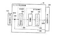
図1において、1は、BSデジタル放送事業者11、第1のCSデジタル放送事業者12、第2のCSデジタル放送事業者13、CATV放送事業者14、地上波デジタル放送事業者15、BSアナログ放送事業者16、あるいは、地上波アナログ放送事業者17、さらには、第1種電気通信事業者18や特別第2種・一般第2種電気通信事業者19等の放送サービス提供事業者(放送事業者)を示す。200は、前記の放送事業者1が多数の番組情報またはデータ情報を利用者に送信する際に用いる各放送事業者毎に固有の特定周波数のキャリア信号である。
【0051】
2a,2b,2cは、前記放送事業者1のうち、利用者が加入契約した放送事業者a,b,cそれぞれが使用している固有の前記キャリア信号200を受信するアンテナ設備または専用の屋外有線ケーブルを接続するための終端設備を構成する第1の接続端子21a,21b,21cと、該第1の接続端子21a,21b,21cそれぞれから入力されたキャリア信号の中から加入契約した放送事業者が用いているキャリア信号を抽出する受信部22a,22b,22cと、抽出されたそれぞれの前記キャリア信号を共通なデジタル信号形式のベースバンド信号(例えば、MPEG−2信号)に変換する信号変換部23a,23b,23cと、共通な信号形式の該ベースバンド信号に変換された信号をそれぞれ出力する第2の接続端子24a,24b,24cとを備えた受信器#1,受信器#2,受信器#3を示す。なお、図1においては、受信器#1 24aの各構成要素即ち第1の接続端子21a、受信部22a、信号変換部23a及び第2の接続端子24aのみを示し、受信器#2 24b及び受信器#3 24cの各構成要素は省略して、図示していない。
【0052】
10は、複合受信配信装置本体を示し、該複合受信配信装置10は、一つまたは複数個の受信器#1,#2,#3 2a,2b,2cの第2の接続端子24a,24b,24cと接続される第3の接続端子31a,31b,31c(図1には、31b,31cの第3の接続端子を省略して、図示していない)を備えた受信器収納スペース#1,#2,#3 3a,3b,3cを一つまたは複数個備えた受信器収納部3と、該受信器収納スペース#1乃至#3 3a乃至3cのいずれかに収納され、第2の接続端子24a乃至24cと第3の接続端子31a乃至31cとが相互接続されて、一つまたは複数個の受信器#1乃至#3 2a乃至2cの信号変換部23a乃至23cが出力する共通な信号形式のベースバンド信号223a乃至223cをそれぞれ第2の接続端子24a乃至24c及び第3の接続端子31a乃至31cを介して、それぞれ231a乃至231cとして取り出し、一括処理して誤り訂正された受信信号241を生成する信号処理部4と、一つまたは複数個の表示装置#1乃至#3 110a乃至110cから送信される番組選択命令によって特定の番組に係わる受信信号251を選択する番組選択部5と、前記番組選択部5から取り出された特定の番組に係わる受信信号251を、前記番組選択命令を送信してきた表示装置#1乃至#3 110a乃至110cのいずれかに通信制御部7を介して送信する番組送信部8と、一つまたは複数個の表示装置#1乃至#3 110a乃至110cから送信されてくる信号を受信する命令受信部9と、番組送信部8及び命令受信部9が表示装置#1乃至#3 110a乃至110cとの間で行う通信を制御する通信制御部7と、さらには、放送事業者1との間で予め個別に加入契約した情報をICカード120とともに管理・制御する加入契約情報管理部6とを構成手段として備えている。
【0053】
なお、番組送信部8及び命令受信部9と表示装置#1乃至#3 110a乃至110cとの間の通信媒体は無線系のものであっても、有線系のものであっても構わない。
また、100は、1つまたは複数個の受信器#1乃至#3 2a乃至2cと1つの複合受信配信装置本体10とから構成される複合受信配信装置を示す。
【0054】
以上のように構成された複合受信配信装置100について、以下その動作を本発明の実施の形態とともに説明する。利用者は図1に示すごとき放送事業者1の中から視聴したい放送事業者を選択し、該放送事業者が配信する信号を受信するアンテナ設備または専用の屋外有線ケーブルを敷設したのち、複数個存在する受信器のうち、該放送事業者が指定する受信器を購入またはレンタルする。また、視聴したい放送事業者が複数になる場合は、それぞれの放送事業者が指定する各受信器を1台ずつ購入またはレンタルする。そして、利用者はかかる一つまたは複数個の受信器を受信器#1乃至#3 2a乃至2cとして複合受信配信装置10の受信器収納部3の受信器収納スペース#1乃至#3 3a乃至3cに収納する。
【0055】
例えば、複合受信配信装置本体10の受信器収納部3が3つの受信器収納スペースを有するとした時、利用者は3つの受信器、すなわち、受信器#1 2a,受信器#2 2b,受信器#3 2cをそれぞれ受信器収納スペース#1 3a,受信器収納スペース#2 3b,受信器収納スペース#3 3cに収納させることが可能である。そして、受信器#1乃至#3 2a乃至2cを受信器収納スペース#1乃至#3 3a乃至3cに収納し、受信器#1乃至#3 2a乃至2c側が有する第2の接続端子24a乃至24cと、複合受信配信装置本体10側が有する第3の接続端子31a乃至31cとが電気的に相互接続されることによって、複合受信配信装置本体10は個々の放送事業者が配信する放送信号を該複合受信配信装置10の内部に取り込むことが可能となる。
【0056】
ここに、受信器#1乃至#3 2a乃至2c内部で実行される受信信号の信号処理は個々の放送事業者のキャリア信号毎に異なるが、信号処理手順は全ての受信器に共通である。即ち、放送事業者は無線または有線を用いて多数の番組または情報信号を特定周波数のキャリア信号200で送信する。特定周波数の該キャリア信号200は、敷設されたアンテナ設備または専用の屋外有線ケーブルにより受信され、該アンテナ設備または専用屋外有線ケーブルに接続された第1の接続端子21a乃至21cを介してそれぞれキャリア信号221a乃至221cとして受信器#1乃至#3 2a乃至2cの受信部22a乃至22cに入力される。次に、放送事業者毎に異なる特定周波数帯域を有するキャリア信号221a乃至221cの中から、受信部22a乃至22cにおいて、契約対象の放送事業者が放送する所定の特定周波数帯域のキャリア信号222a乃至222cが抽出・選択されて、信号変換部23a乃至23cに入力される。
【0057】
信号変換部23a乃至23cにおいて、入力されたキャリア信号222a乃至222cは共通なデジタル信号形式(例えば、MPEG−2信号形式)のベースバンド信号223a乃至223cに変換され、第2の接続端子24a乃至24cに出力される。受信器#1乃至#3 2a乃至2cは、複合受信配信装置本体10の受信器収納スペース#1乃至#3 3a乃至3cにそれぞれ収納されていて、第2の接続端子24a乃至24cと第3の接続端子31a乃至31cとがそれぞれ電気的に接続されているので、第2の接続端子24a乃至24cからの出力信号が、そのまま第3の接続端子31a乃至31cからのそれぞれの出力信号231a乃至231cとなり、該出力信号231a乃至231cも前記の共通なデジタル信号形式のベースバンド信号223a乃至223cと同一のものである。
【0058】
受信器収納スペース#1乃至#3 3a乃至3cから出力される共通なデジタル信号形式の前記ベースバンド信号231a乃至231cは、信号処理部4において伝送中の妨害波等による信号の読み取り誤りが訂正処理され、受信信号241として出力される。ここに、該受信信号241は、契約対象の放送事業者が提供する複数の放送番組、放送データや個別情報あるいは各種サービス情報が多重化されている信号である。
【0059】
番組選択部5は番組選択回路とスクランブル解除回路とを有している。番組選択回路は、命令受信部9で受信したチャンネル信号291を、通信制御部7を介して、番組選択信号271bとして受信することにより利用者が指定している番組、データあるいはサービス情報を識別し、前記受信信号241の中から、利用者が指定している特定番組、特定データあるいは特定サービス情報に関する信号を選択する。該信号がスクランブルされている場合には、スクランブル解除回路はICカード120に蓄積されている鍵情報を加入契約情報管理部6を介して取り出して、該信号のスクランブルを解除して視聴可能な受信信号251を生成する。即ち、番組選択回路は、利用者が選択指示する特定番組、特定データあるいは特定サービス情報に関する信号を受信信号241の中より選択するためのものである。また、スクランブル解除回路は、利用者が選択指示する特定番組、特定データあるいは特定サービス情報に関する信号がスクランブルされている場合、該信号のスクランブルを解除するためのものである。
なお、前記受信信号241は、前述のとおり、全ての放送事業者の放送情報に関して共通なデジタル信号形式を有する信号であり、放送事業者毎に異なる信号処理を行なう必要はない。
【0060】
一方、命令受信部9で受信された、利用者が命令(選択指示)している特定番組、特定データあるいは特定サービス情報の選択指示用のチャンネル信号291は、通信制御部7を介して、2つの信号即ち番組選択信号271bと開示判定用信号271cとに分けられる。番組選択信号271bは、番組選択部5に入力され、前述のように、受信信号241の中から利用者が命令(選択指示)する特定番組、特定データあるいは特定サービス情報に関する信号を選択するために用いられる。一方、開示判定用信号271cは、加入契約情報管理部6に入力され、利用者が命令(選択指示)する特定番組、特定データあるいは特定サービス情報に関する信号が加入契約情報に照らして開示可能なチャンネルか否かを判別し、該チャンネルの開示の可否を示す開示可否判別信号261として番組選択部5に送られる。開示可否判別信号261が開示可能であることを示している場合、番組選択部5内の番組選択回路で前記番組選択信号271bに基づいて選択された特定番組、特定データあるいは特定サービス情報に関する前記信号は、スクランブル解除回路に送られ、スクランブルを解除した後、受信信号251として、通信制御部7に送られる。
なお、該受信信号251は、前述のとおり、全ての放送事業者の放送情報に関して共通なデジタル信号形式を有する信号であり、放送事業者毎に異なる信号処理を行なう必要はない。
【0061】
通信制御部7は、利用者が命令(選択指示)してきた前記チャンネル信号291を送付してきた表示装置#1乃至#3 110a乃至110cの識別番号をタグデータとして受信信号251に付加してタグデータ付受信信号271aを生成して番組送信部8に送る。番組送信部8は、タグデータ付受信信号271aにある表示装置の識別番号を示すタグデータに基づいて目的とする表示装置#1乃至#3 110a乃至110cのいずれかを識別し、目的の該表示装置に向けて、無線信号201a,201b,201cのいずれか、または、有線の信号として伝送する。ここで、複数の表示装置から、同時に同一の番組データあるいはサービス情報の表示要求がある場合には、目的とする複数の表示装置に向けて同時に無線または有線の信号で伝送する。
【0062】
以上のように、図1に示した複合受信配信装置100は、利用者が選択した一つまたは複数の放送事業者が指定する各受信器を1台ずつ収納することにより、それぞれの放送事業者が提供する番組、データあるいはサービス情報を一つまたは複数個の表示装置に送信することが可能である。
【0063】
次に、図1に示した複合受信配信装置本体における受信器収納部の構造について説明する。図2は、図1に示した複合受信配信装置の受信器収納部を正面から見た場合の模式図である。
【0064】
図2において、3a1,3b1,3c1は、それぞれ受信器収納スペース#1,#2,#3 3a,3b,3cの受信器収納用の挿入口であり、横長の矩形状空間構造を有している。即ち、各受信器収納スペース#1乃至#3 3a乃至3cの収納孔の形状は直方体状の空間立体形状を形成している。さらに、32a,32b,32cは、受信器#1,#2,#3 2a,2b,2cを挿入する際の誤挿入防止用の挿入ガイドであり、直方体状の空間立体形状を有する前記収納孔に突出した直方体状の突起構造を有し、各受信器底面に備えられている溝と摺動して嵌合される。また、33a,33b,33cは、収納された受信器#1,#2,#3 2a,2b,2cをそれぞれ受信器収納スペース#1,#2,#3 3a,3b,3cから取り出すための受信器取り出しボタンである。なお、31a,31b,31cは、前記の図1に示した第3の接続端子であり、各受信器収納スペース#1,#2,#3 3a,3b,3cの収納孔の奥に設けられた壁に配設されていて、受信器#1,#2,#3 2a,2b,2cが収納された際に、受信器#1,#2,#3 2a,2b,2cに備えられている第2の接続端子24a,24b,24cとそれぞれ嵌合され、電気的に接続される。
なお、上述した受信器収納部の構造は一実施例を示すものに過ぎず、例えば、受信器収納用の挿入口の形状が横長の矩形状ではなく、縦長や正方形状など他の形状からなっていても良く、また、挿入ガイドを取り付ける位置も底面に限らず、側面あるいは上面であってもかまわない。
【0065】
以上のように構成された複合受信配信装置本体10の受信器収納スペース#1乃至#3 3a乃至3cの構造について、以下、図2を参照しながら、さらに説明する。受信器収納スペース#1乃至#3 3a乃至3cのそれぞれの収納孔(幅×高さ×奥行:A×B×C)、並びに、挿入ガイド32a乃至32c(幅×高さ×奥行:D×E×F)の外形形状及び外形寸法の大きさを全て同じにすることとし、利用者は任意の受信器収納スペースに任意の放送事業者用の受信器を収納することができる構造としている。受信器収納スペースの外形形状及び外形寸法の大きさを全て同じとすれば、かかる受信器収納スペースに挿入する受信器の大きさを同じにすることが必要となり、かかる受信器を製造するメーカは、受信器の外形形状及び外形寸法を全て同じものとする結果、各製造メーカの受信器の特徴付与は各受信器の機能・性能・価格面によって行わなければならなくなる。而して、利用者は、受信器を購入する際、外形形状や外形寸法によらず、機能・性能・価格面のみから、最も好ましい受信器を得る機会を獲得することができる。たとえ、外形形状と外形寸法が異なる受信器がある場合においても、各製造メーカが用意する収納用アダプタを該受信器に付着させることにより、同一の外形形状、外形寸法とさせ、受信器収納スペースに収納させる。
【0066】
また、挿入ガイド32a,32b,32cを設けることにより、利用者は受信器収納スペースのそれぞれの挿入ガイド32a,32b,32cに沿って各受信器に有する溝を合わせて受信器収納スペースの挿入口3a1,3b1,3c1に嵌め込まなければ、受信器が受信器収納スペース3a,3b,3cに収まらないため、受信器の取り付け誤りを防止する役割を果たさせることができる。
【0067】
また、受信器収納スペースのそれぞれの挿入口3a1,3b1,3c1にはバネまたはギア等からなる開閉式の蓋が備えられており、受信器が収納されていない状態においては、該蓋が挿入口3a1,3b1,3c1を覆う機構をなしている。したがって、受信器が収納されていない受信器収納スペースから当該複合受信配信装置100の内部へほこりやゴミなどが侵入することを防止することができ、当該複合受信配信装置100の故障の発生頻度を低減することができる。
【0068】
受信器取り出しボタン33a,33b,33cは、図1に示す受信器側が有する第2の接続端子24a,24b,24cと複合受信配信装置本体10が有する第3の接続端子31a,31b,31cとが嵌合されている電気的な接触状態を手動的または自動的に分離するための取り出しボタンである。利用者は、受信器取り出しボタン33a,33b,33cを押すことにより、前記嵌合状態を解除させ、受信器を取り出すことが容易に可能となる。例えば、利用者が放送事業者を変更する際、取り出しボタン33a乃至33cを利用して、受信器の脱着を行い、取り替えればよいことになる。
【0069】
なお、受信器収納スペース#1,#2,#3 3a,3b,3cのそれぞれの第3の接続端子31a,31b,31cのすべてについて、形状、ピン配列、接続端子位置を同じとしている。したがって、複合受信配信装置本体10に装着できる受信器はいずれの放送事業者用の受信器であっても、すべて全く同じ形状,配列,接続端子位置を有する第2の接続端子24a,24b,24cを備えており、それぞれ、第3の接続端子31a,31b,31cと嵌合し、電気的な接続状態を形成する。而して、利用者は、放送事業者あるいは受信器の製造メーカに関係なく、同一形状,同一接続端子を有する受信器を複合受信配信装置本体10に収納し、電気的に接続することができる。
【0070】
又、受信器の第2の接続端子24a,24b,24cのそれぞれを構成する複数の端子は前述の如く同一の配列となっているが、かかる複数の端子のうちの一部の端子は、受信器の種別、即ち、該受信器が受信できる放送サービスの種類を示す端子となっている。
以下、かかる受信器の種別を判別する方法について図3を用いて説明する。
図3は、第2の接続端子の端子配列の一実施形態を示す構成図である。受信器2a,2b,2cが有する第2の接続端子24a,24b,24c(図3においては、符号24として示している)は、共通なデジタル信号形式のベースバンド信号を外部に出力する端子も含めて、該受信器2a,2b,2cを電気的に動作させるに必要な各種の信号、電源、地気などの電気的信号を入出力する主端子部60と、該受信器が受信できる放送サービスの種類を示す副端子部61とを有している。副端子部61は複数の副端子a乃至d 61a乃至61dから構成され、該副端子a乃至d 61a乃至61dの装着の有無或いは電気的に通電するか否かの組合せによって、該受信器が受信できる放送サービスの種類を示すようにしている。
【0071】
例えば、副端子a乃至d 61a乃至61dの数を4個と定めた場合、図3に示す4個の副端子a乃至d 61a乃至61dそれぞれの端子位置に意味を持たせる。即ち、例えば、副端子a 61aのみが装着されている場合は、地上波アナログ放送受信用の受信器であることを示し、副端子a 61aと副端子d 61dとが装着されている場合は、BSデジタル放送受信用の受信器であることを示す。
従って、副端子a乃至d 61a乃至61dの4個を有している場合、該副端子の装着の有無或いは電気的通電状態の有無の組み合せは16通りになり、それぞれのパターンに対して予め定義付けることができる放送サービスの種類は16種類となる。
【0072】
かかる副端子61a乃至61dを有する受信器の第2の接続端子24a,24b,24cを複合受信配信装置本体10の受信器収納スペース内にあるそれぞれの第3の接続端子31a,31b,31cに電気的に接続した時、第3の接続端子31a,31b,31cは電気的に通電する受信器の第2の接続端子24a,24b,24cの副端子61a乃至61dの状態を読み取ることにより、かかる副端子の通電パターンから第3の接続端子31a,31b,31cに接続された受信器が受信できる放送サービスの種類、即ち、受信器の種別を、複合受信配信装置本体10が判別することが可能となる。
【0073】
また、図4並びに図5は、それぞれ本発明にかかる複合受信配信装置の実施形態に係るデジタル放送受信器並びにアナログ放送受信器の構成を示すものである。本実施形態においては、複数のキャリア信号を混合させて入力させる混合入力手段を備える受信器を提供している。
【0074】
図4において、2Dはデジタル放送受信器であり、デジタル放送事業者が用いているキャリア信号を受信するアンテナ設備または専用屋外有線ケーブルを接続する第1の接続端子21Dと、該アンテナ設備または該専用屋外有線ケーブルで受信した信号から加入契約した事業者が用いているキャリア信号を抽出するキャリア選択部25Dを有する受信部22Dと、復調部26DとFEC(Forward Error Correction)デコーダ27Dとを有し、共通な信号形式のベースバンド信号に変換する信号変換部23Dと、共通な信号形式のベースバンド信号に変換された信号を外部へ出力する第2の接続端子24Dと、前記アンテナ設備または前記専用屋外有線ケーブルからのキャリア信号を第1の接続端子21D及び第2の接続端子24Dの特定端子を介してキャリア選択部25Dへ混合して入力するタップ50Dとを備えている。
【0075】
一方、図5においては、2Aはアナログ放送受信器であり、アナログ放送事業者が用いているキャリア信号を受信するアンテナ設備または専用屋外有線ケーブルを接続する第1の接続端子21Aと、該アンテナ設備または該専用屋外有線ケーブルで受信した信号から加入契約した事業者が用いているキャリア信号を抽出するキャリア選択部25Aを有する受信部22Aと、復調部26Aとアナログ−デジタル信号変換部(AD変換部)28Aとを有し、共通な信号形式のベースバンド信号に変換する信号変換部23Aと、共通な信号形式の信号形式のベースバンド信号に変換された信号を外部へ出力する第2の接続端子24Aと、前記アンテナ設備または前記専用屋外有線ケーブルからのキャリア信号を第1の接続端子21A及び第2の接続端子24Aの特定端子を介してキャリア選択部25Aへ混合して入力するタップ50Aとを備えている。
【0076】
次に、本発明にかかる前記混合入力手段に関する実施形態について、図1,図4及び図5を用いて説明する。図1に示すように、複合受信配信装置本体10の内部には、外部入力端子となる第4の接続端子41と、第4の接続端子41と接続する接続ケーブル42と、接続ケーブル42上にタップ51a,51b,51cとを有しており、タップ51a乃至51cはそれぞれ受信器収納スペース#1乃至#3 3a乃至3cにある第3の接続端子31a乃至31cの特定端子に接続される構成となっている。ここで、複数のキャリア信号を混合させる手段として、図4及び図5に示すように、受信器の第2の接続端子24D,24Aの特定端子とタップ50D,50Aとの間には、第2の接続端子24D,24Aの前記特定端子に第3の接続端子31a乃至31cのいずれかの前記特定端子を介して入力されてくる別のキャリア信号をそれぞれの受信部22D,22Aに伝送する接続ケーブル29D,29Aを有する構成をしている。
【0077】
利用者が、複数の放送事業者のアンテナ設備等からの別々のキャリア信号を混合させて入力させることができる受信器を用いる場合、利用者は、第1の接続端子に接続したアンテナ設備とは別の放送事業者のキャリア信号を受信するためのアンテナ設備を接続する接続ケーブルを第4の接続端子41に接続する。従って、複合受信配信装置本体10内の接続ケーブル42上には、別の放送事業者のキャリア信号が伝送されることになる。そして、別の放送事業者の該キャリア信号は、タップ51a乃至51cのいずれかを介して受信器収納スペース#1乃至#3 3a乃至3cに備えられた第3の接続端子31a乃至31cの前記特定端子のいずれかに供給される。
【0078】
例えば、複合受信配信装置本体10の受信器収納スペース#1 3aに、第4の接続端子41に接続されている放送事業者のキャリア信号を受信できるデジタル放送受信器2Dが収納されている場合、該放送事業者が配信する特定周波数のキャリア信号200は、第4の接続端子41,接続ケーブル42,タップ51a,第3の接続端子31aの前記特定端子を経由して、デジタル放送受信器2D内の第2の接続端子24Dの前記特定端子から接続ケーブル29D上に伝送される。その後、第4の接続端子41に接続されている放送事業者のキャリア信号200はタップ50Dを介して受信部22Dに供給される。すなわち、利用者は第1の接続端子21Dだけでなく、第4の接続端子41に、アンテナ設備が接続された接続ケーブルあるいは専用屋外有線ケーブルからの接続ケーブルを接続することにより、所望のキャリア信号を受信できることが可能となる。
【0079】
【発明の効果】
本発明にかかる複合受信配信装置は、利用者が選択した一つまたは複数の放送事業者毎の受信器を1台ずつ1台の複合受信配信装置本体内に収納することができ、該受信器において各放送事業者の放送信号を共通なデジタル信号形式に変換させて、該共通の信号に基づいて各種の信号受信処理を行うので、各放送事業者毎に固有の配線を敷設しなくても、各放送事業者が配信する番組、データあるいはサービス情報を一つまたは複数の表示装置に送信することが可能である。したがって、利用者がある特定の放送事業者の放送サービスを任意の場所で視聴できる環境を整えようとする場合、該放送サービス用の固有のアンテナ設備を取り付けて、固有の受信器1台を前記複合受信配信装置本体内に収納した後の配線作業は該アンテナ設備と複合受信配信装置本体内に収納した該受信器との間をケーブル接続するだけで任意の場所で該放送サービスを視聴できる環境を構築することができる。
【0080】
また、利用者がある特定の放送サービスを複数の任意の場所で同時に視聴できる環境を整えようとする場合にも、該特定サービスを配信する放送事業者に固有の受信器を1台のみ購入あるいはレンタルするだけで複数の任意の場所で同時に視聴できる環境を構築することができる。
【0081】
さらに、各放送事業者に固有の受信器の外形形状及び外形寸法を全て同一とさせることにより、受信器の大きさや形状に囚われることなく、受信器本来の機能面、性能面及び価格面についてのみ検討して最も好ましい受信器を購入あるいはレンタルすることができる。
【図面の簡単な説明】
【図1】 本発明が適用される複合受信配信装置の一構成例を示す図である。
【図2】図1に示した複合受信配信装置の受信器収納部を正面から見た場合の模式図である。
【図3】 第2の接続端子の端子配列の一実施形態を示す構成図である。
【図4】 本発明にかかる複合受信配信装置の一実施形態に係るデジタル放送受信器の構成を示すものである。
【図5】 本発明にかかる複合受信配信装置の他の実施形態を説明するためのアナログ放送受信器の構成を示すものである。
【図6】 従来の宅内の受信配線設備の系統構成図である。
【符号の説明】
1…放送サービス提供事業者、2a,2b,2c…受信器#1,受信器#2,受信器#3、2D…デジタル放送受信器、2A…アナログ放送受信器、3…受信器収納部、3a,3b,3c…受信収納スペース#1,受信収納スペース#2,受信収納スペース#3、3a1,3b1,3c1…受信収納スペース#1の挿入口,受信収納スペース#2の挿入口,受信収納スペース#3の挿入口、4…信号処理部、5…番組選択部、6…加入契約情報管理部、7…通信制御部、8…番組送信部、9…命令受信部、10…複合受信配信装置本体、11…BSデジタル放送事業者、11a…BSアンテナ部、12…CSデジタル放送事業者#1、12a…第1のCSデジタル放送受信用アンテナ部、13…CSデジタル放送事業者#2、13a…第2のCSデジタル放送受信用アンテナ部、14…CATV放送事業者、14a…屋外有線ケーブル、15…地上波デジタル放送事業者、15a…地上波デジタル放送受信用アンテナ部、16…BSアナログ放送事業者、17…地上波アナログ放送事業者、17a…地上波アナログ放送受信用アンテナ部、18…第1種電気通信事業者、19…特別第2種・一般第2種電気通信事業者、21a,21b,21c…第1の接続端子、21A,21D…アナログ,デジタル放送受信器の第1の接続端子、22a,22b,22c…受信部、22A,22D…アナログ,デジタル放送受信器の受信部、23a,23b,23c…信号変換部、23A,23D…アナログ,デジタル放送受信器の信号変換部、24,24a,24b,24c…第2の接続端子、24A,24D…アナログ,デジタル放送受信器の第2の接続端子、25A,25D…アナログ,デジタル放送受信器のキャリア選択部、26A,26D…アナログ,デジタル放送受信器の復調部、27D…デジタル放送受信器のFECデコーダ、28…AD変換部、28A…アナログ放送受信器のAD変換部、29A,29D…アナログ,デジタル放送受信器内の接続ケーブル、31a,31b,31c…第3の接続端子、32a,32b,32c…挿入ガイド、33a,33b,33c…受信器取り出しボタン、41…第4の接続端子、42…接続ケーブル、50A,50D…アナログ,デジタル放送受信器のタップ、51a,51b,51c…タップ、60…主端子部、61…副端子部、61a,61b,61c,61d…副端子a,副端子b,副端子c,副端子d、100…複合受信配信装置、110a,110b,110c…表示装置#1,表示装置#2,表示装置#3、120…ICカード、200…キャリア信号、201a,201b,201c…無線信号、221a,221b,221c,221A,221D…キャリア信号、222a,222b,222c…抽出キャリア信号、223a,223b,223c,223A,223D,231a,231b,231c…ベースバンド信号、224…アナログ信号形式のベースバンド信号、241,251…受信信号、261…開示可否判別信号、271a…タグデータ付受信信号、271b…番組選択信号、271c…開示判定用信号、291…チャンネル信号、411a,411c…BSデジタル用STB、412a,412b…CS#1用STB、413a…CS#2用STB、414a,414b…CATV用STB、415a,415b…地上波デジタル用STB、416b…BSアナログ受信手段、420a,420b,420c…AVセレクタ手段、430a,430b,430c…テレビジョン受信機、500…混合器、501,502,503,504,505…分配器、510,511a,511b,511c,512a,512b,513a,513c,514a,514b,515a,515b…同軸ケーブル、521a,521c,522a,522b,523a,524a,524b,525a,525b…接続ケーブル、550…宅内配線システム。[0001]
BACKGROUND OF THE INVENTION
The present invention relates to a composite reception and distribution apparatus capable of receiving and distributing a plurality of broadcasts, and in particular, receives a broadcast program or broadcast data carrier signal specific to each broadcaster and converts it into a baseband signal in a common signal format. And receiving a plurality of receivers in one receiving and distributing device, and receiving broadcast signals of a plurality of broadcasters, and for a plurality of arbitrary display devices The present invention relates to a composite reception distribution apparatus capable of distributing a reception signal.
[0002]
[Prior art]
Conventional broadcasting forms include terrestrial analog broadcasting, BS (Broadcasting Satellite) analog broadcasting, analog CATV broadcasting, and CS (Communication Satellite: digital broadcasting) digital broadcasting. Has been made. With the advancement of digital technology in recent years, the broadcasting format has also been digitized, and not only CS digital broadcasting but also the analog broadcasting described above is going to shift to digital broadcasting (BS digital broadcasting, digital CATV broadcasting, terrestrial digital broadcasting). BS analog broadcasting and terrestrial analog broadcasting are about to be terminated after a certain transition period.
[0003]
In digital broadcasting, video signals and audio signals are digitally compressed and transmitted by, for example, MPEG-2 (Moving Picture Experts Group-2) system, and it is possible to transmit higher quality signals than existing analog broadcasting. In addition, the frequency utilization efficiency is improved and the number of channels can be increased. In digital broadcasting, it is possible to provide services such as data broadcasting as well as video and audio.
[0004]
Currently, CS digital broadcasting service has already started. In CS digital broadcasting, many channels for broadcasting contents such as sports, movies, music, and news are prepared, and several hundred channels are secured as the number of channels of one satellite.
[0005]
Furthermore, BS digital broadcasting, digital CATV broadcasting, and terrestrial digital broadcasting services are about to be started in the future. Some CS digital broadcasting satellites have been launched, and some CS digital broadcasting services are about to start. Thus, in such various digital broadcasting services, preparations are being made to prepare channels for providing various more interesting programs.
[0006]
When various types of digital broadcasting services appear, users who want to enjoy various broadcasting services by subscribing to a plurality of digital broadcasting services in addition to the current analog broadcasting service will increase.
[0007]
When receiving these digital broadcasts, a dedicated broadcast receiver STB (Set Top Box, hereinafter referred to as STB) for decoding digital video signals and digital audio signals specific to each digital broadcast is required. is there.
[0008]
However, basically, such dedicated STBs need to be arranged one-to-one with respect to a display device such as a television receiver, so that digital broadcasting can be viewed only on the display device connected to the dedicated STB. I can't.
[0009]
Hereinafter, an example of receiving and distributing digital broadcasting when the conventional technology is applied will be described with reference to a system configuration diagram of a conventional in-house reception wiring facility shown in FIG. In FIG. 6,
[0010]
11a is a BS antenna unit for receiving BS digital broadcast and BS analog broadcast, 12a is a first CS digital broadcast receiving antenna unit for receiving radio waves from the first communication satellite, and 13a is from the second communication satellite. A second CS digital broadcast receiving antenna unit for receiving radio waves, 15a is a terrestrial digital broadcast receiving antenna unit, and 17a is a terrestrial analog receiving antenna unit.
[0011]
A
[0012]
[0013]
521a and 521c are connections for externally inputting the BS broadcast program video output signals descrambled by the BS
[0014]
[0015]
In constructing the in-
[0016]
As a first procedure, a user receives a plurality of broadcast signals distributed by each broadcast service provider (broadcaster) in order to view a plurality of digital broadcast services in addition to the current analog broadcast. Lay an antenna or multiple outdoor dedicated cables.
[0017]
As a second procedure, each user decides in advance a viewing location (room) for viewing each broadcasting service, and in order to allow a specific broadcasting service to be viewed at the viewing location, In order to view the specific broadcast service, a distributor is further connected to the coaxial cable connected to the antenna or the like installed for each broadcast service, and a plurality of viewing locations are respectively connected via the distributor. Wire the coaxial cable for indoor wiring.
[0018]
As a third procedure, the user purchases or rents a dedicated STB designated by each broadcaster. At this time, if the user wants to watch a specific broadcaster's broadcast at a plurality of viewing locations at the same time, it is necessary to prepare a plurality of dedicated STBs designated by each broadcaster for each of the plurality of viewing locations. .
[0019]
As a fourth procedure, the user connects the dedicated STB to the indoor wiring coaxial cable connected to the corresponding broadcaster antenna, and further, the dedicated STB and television. Connect to a display device such as a receiver with a connection cable.
[0020]
As described above, through the first to fourth construction procedures, the user can receive a broadcast signal distributed free of charge by the broadcaster at each viewing location and project a service such as a program video on the display device. .
[0021]
On the other hand, a broadcast service provided by a broadcaster includes a pay program, and when receiving such a pay broadcast, a so-called limited reception method is adopted. Therefore, in order for the user to view the broadcast of the conditional access system, it is necessary to make a predetermined subscription contract in advance.
[0022]
That is, as a fifth procedure, the user enters a predetermined subscription contract with the broadcaster in order to view the broadcast of the limited reception method. In general, an IC card is used as means for managing information on such a subscription contract. The IC card is used by being attached to a dedicated STB corresponding to each broadcaster purchased or rented, and the dedicated STB is equipped with an IC card drive capable of reading and writing the IC card. Yes.
[0023]
In addition to broadcast programs, broadcasters also provide individual information (contract information, messages addressed to individuals, etc.) and program information such as program guides in order to provide each user with a program in accordance with the contents of the subscription contract. Send to users. Each user receives the individual information and the program information using a dedicated STB corresponding to each broadcaster, and stores it in the IC card inserted in the IC card drive of the dedicated STB. In addition, regarding the received signal related to the pay broadcast program input to the dedicated STB, the contents of the IC card storing the contract information and the key for releasing the scramble are read out and referred to by the IC card drive. The scrambled received signal is decoded, and a pay broadcast program can be viewed on the display device.
[0024]
In the in-
[0025]
In the room b, it is possible to enjoy five types of broadcasting services of the first CS digital broadcasting, CATV broadcasting, terrestrial digital broadcasting, BS analog broadcasting, and terrestrial analog broadcasting.
[0026]
In room c, two types of broadcasting services, BS digital broadcasting and terrestrial analog broadcasting, can be enjoyed.
[0027]
In room d, 0 types of broadcasting services can be enjoyed.
[0028]
[Problems to be solved by the invention]
However, in the configuration and construction procedure of the in-home wiring system as described above, when a user intends to enjoy a broadcast service of a specific broadcaster at an arbitrary location in the home, the following problems are encountered. ing.
As a problem (1), as shown in the above-described second procedure, when a user wants to not watch a broadcast service of a specific broadcaster, a viewing place (room) for viewing the broadcast service is set in advance. A coaxial cable connected to an antenna laid to receive the broadcast service signal is laid to the viewing location, connected to the dedicated STB for the broadcast service, and further connected via a connection cable. The broadcast service cannot be enjoyed unless the dedicated STB is connected to a television receiver. Here, when the user wants to view at a plurality of viewing locations, the coaxial cable connected to the antenna is first connected to the distributor, and further the coaxial cable is laid from the distributor to each of the plurality of viewing locations. A dedicated STB for the broadcasting service must be provided every time.
[0029]
That is, when trying to prepare an environment in which a user can view a specific broadcast service at a plurality of viewing locations, a plurality of coaxial cables distributed from a distributor connected to the specific broadcast service receiving antenna are desired. It is necessary to individually pull up to each viewing location. Furthermore, it is necessary to perform such pull-in work for each broadcast service of a plurality of broadcasters.
[0030]
As an issue (2), as shown in the third procedure described above, when a user views a broadcast service of a specific broadcaster at a plurality of viewing locations at the same time, a dedicated STB designated by the broadcaster Must be purchased or rented for each viewing location.
[0031]
That is, when trying to prepare an environment in which a user can simultaneously view a broadcast service of a specific broadcaster at a plurality of arbitrary locations, the problem (1) is solved and a plurality of dedicated STBs are further provided. Need to buy or rent.
[0032]
As an issue (3), when a user intends to receive broadcasting services of a plurality of broadcasters, it is necessary to purchase or rent dedicated STBs corresponding to each, but the sizes of the STBs are not uniform. Therefore, the user's consideration regarding the location of the STB becomes complicated.
[0033]
The present invention has been made in view of the above problems, and a first object of the present invention is to provide an environment in which a user can view a broadcast service of a specific broadcaster at an arbitrary place. In this case, an antenna for receiving a specific signal of the broadcast service and a broadcast receiving apparatus STB capable of decoding the signal (hereinafter, in the present invention, in order to prevent the confusing terminology with the conventional STB, A cable connection between the receiver and each display device by simply performing a cable connection between the receiver and each display device, and an environment where the viewer can view the cable at any place is provided. It is to provide a composite reception delivery apparatus capable of
[0034]
A second object of the present invention is to provide a dedicated receiver designated by a broadcaster when the user intends to prepare an environment in which a user can view a broadcast service of a specific broadcaster at a plurality of viewing locations simultaneously. An object of the present invention is to provide a composite reception / distribution apparatus capable of constructing an environment in which only one can be purchased or rented and can be viewed simultaneously at any plurality of viewing locations.
[0035]
The third object of the present invention is captured by the external shape and external dimensions of each dedicated receiver required for each broadcaster even when the user tries to enjoy the broadcast service of a plurality of broadcasters. It is an object of the present invention to provide a composite reception delivery apparatus that can accommodate only receivers of the same structure that are not necessary.
[0036]
[Means for Solving the Problems]
In order to achieve the above object, the present invention provides a composite reception and distribution apparatus that is installed in a home and receives and distributes a broadcast program or broadcast data distributed based on one or more specific signal formats. A receiving means for extracting and receiving a carrier signal of a broadcast program or broadcast data distributed based on one or a plurality of unique signal formats, and converting the received carrier signal into a baseband signal of a common signal format A rectangular parallelepiped receiver including a signal converting unit, accommodating one or a plurality of the receivers, and outputting the baseband signal converted by the signal converting unit of the receiver One or a plurality of receiver storage means, and a signal processing means for generating a digital signal by performing signal processing on the baseband signal output from the receiver storage means; Program selection means for selecting and outputting an output signal related to a specific broadcast program or broadcast data included in the digital signal from the signal processing means, and one or a plurality of the output signals from the program selection means An apparatus for receiving a carrier signal distributed based on the specific signal format, or an outdoor wired cable. And a second connection means for outputting the baseband signal to the signal processing means of the composite reception / distribution apparatus main body, and the composite reception / distribution apparatus main body. Is connected to the second connection means in order to input the baseband signal to the signal processing means for each of one or a plurality of the receiver accommodating means. The receiver is separated from the main body of the composite reception and delivery apparatus, and the receiver is stored in the receiver storage means, whereby the second connection means and the second connection means are provided. 3 is interconnected, and the baseband signal is input to the signal processing means, and in the receiver, mixed input means for mixing and inputting a plurality of carrier signals is 1 is arranged between the connection means and the signal conversion means, the mixed input means and the second connection means are connected, and the composite reception delivery apparatus main body is connected to the first connection means. Is a fourth connection means for inputting another carrier signal, and a plurality of the carrier signals inputted from the fourth connection means are arranged for each of the plurality of receiver accommodating means. Distribute to third connection means Signal distribution means, and separately from the first connection means, the other carrier signal from the fourth connection means is supplied to the signal distribution means, the third connection means, and the second connection means. To be input to the mixing input meansIn other words, the composite reception and delivery apparatus is characterized.
[0050]
DETAILED DESCRIPTION OF THE INVENTION
Hereinafter, embodiments of the present invention will be described with reference to the drawings.
FIG. 1 shows the present invention.Is appliedOf the composite reception delivery deviceoneConstitutionExampleIndicationFigureso,
In FIG. 1,
[0051]
2a, 2b, and 2c are antenna facilities for receiving the
[0052]
[0053]
Note that the communication medium between the program transmitting unit 8 and the command receiving unit 9 and the
[0054]
The operation of the composite
[0055]
For example, when the
[0056]
Here, the signal processing of the received signals executed in the
[0057]
In the signal converters 23a to 23c, the
[0058]
The baseband signals 231a to 231c in the common digital signal format output from the receiver
[0059]
The program selection unit 5 has a program selection circuit and a descrambling circuit. The program selection circuit identifies the program, data or service information designated by the user by receiving the
As described above, the
[0060]
On the other hand, the
Note that the received
[0061]
The communication control unit 7 adds the identification numbers of the
[0062]
As aboveAs shown in FIG.The composite receiver /
[0063]
next,As shown in FIG.The structure of the receiver storage unit in the composite reception delivery apparatus main body will be described. FIG.As shown in FIG.Composite reception delivery deviceReceipt ofIt is a schematic diagram at the time of seeing a belief storage part from the front.
[0064]
In FIG. 2, 3a1, 3b1, 3c1Are receiver insertion slots for receiver
Note that the structure of the receiver storage unit described above is merely an example. For example, the shape of the insertion slot for receiving the receiver is not a horizontally long rectangular shape, but is formed in another shape such as a vertically long or square shape. The position where the insertion guide is attached is not limited to the bottom surface, and may be the side surface or the top surface.
[0065]
The structure of the receiver
[0066]
Further, by providing the insertion guides 32a, 32b, and 32c, the user can align the groove of each receiver along the respective insertion guides 32a, 32b, and 32c of the receiver storage space, and insert the insertion holes of the receiver storage space. 3a1, 3b1, 3c1If it is not fitted in the receiver, the receiver does not fit in the
[0067]
Also, each
[0068]
The receiver take-out
[0069]
Note that the shape, pin arrangement, and connection terminal position are the same for all of the
[0070]
The plurality of terminals constituting each of the
Hereinafter, a method for determining the type of the receiver will be described with reference to FIG.
FIG. 3 is a configuration diagram illustrating an embodiment of a terminal arrangement of the second connection terminals. The
[0071]
For example, when the number of the sub terminals a to
Therefore, when there are four subterminals a to
[0072]
The
[0073]
4 and 5 are respectively a composite reception delivery apparatus according to the present invention.The fruitTo the formPerson in charge1 shows the configuration of a digital broadcast receiver and an analog broadcast receiver. In the present embodiment, a receiver is provided that includes mixed input means for mixing and inputting a plurality of carrier signals.
[0074]
In FIG. 4, 2D is a digital broadcast receiver, which includes a
[0075]
On the other hand, in FIG. 5, 2A is an analog broadcast receiver, which includes a
[0076]
Next, an embodiment relating to the mixing input means according to the present invention will be described with reference to FIGS. As shown in FIG. 1, the composite reception delivery apparatus
[0077]
When a user uses a receiver capable of mixing and inputting different carrier signals from a plurality of broadcaster's antenna facilities, etc., the user refers to the antenna facility connected to the first connection terminal. A connection cable for connecting antenna equipment for receiving a carrier signal of another broadcaster is connected to the
[0078]
For example, in the receiver
[0079]
【The invention's effect】
The composite reception / distribution apparatus according to the present invention can store one or more receivers for each broadcaster selected by the user in a single composite reception / distribution apparatus main body. The broadcast signal of each broadcaster is converted into a common digital signal format, and various signal reception processes are performed based on the common signal, so there is no need to lay a unique wiring for each broadcaster. It is possible to transmit a program, data or service information distributed by each broadcaster to one or a plurality of display devices. Therefore, when trying to prepare an environment in which a user can view a broadcast service of a specific broadcaster at an arbitrary place, a unique antenna facility for the broadcast service is attached, and one unique receiver is attached. The wiring work after being housed in the composite receiver / distributor main body is an environment in which the broadcast service can be viewed at any place simply by connecting a cable between the antenna equipment and the receiver housed in the composite receiver / distributor main body. Can be built.
[0080]
In addition, when trying to prepare an environment in which a user can view a specific broadcast service at a plurality of arbitrary locations at the same time, only one receiver unique to the broadcaster distributing the specific service is purchased or It is possible to construct an environment that allows viewing at a plurality of arbitrary locations by simply renting.
[0081]
Furthermore, by making all the receiver's unique external shape and dimensions unique to each broadcaster, it is not limited to the size and shape of the receiver, but only the original functional, performance and price aspects of the receiver. The most preferred receiver can be purchased or rented after consideration.
[Brief description of the drawings]
FIG. 1 shows the present invention.Is appliedOf the composite reception delivery deviceoneConstitutionExampleShowFigureIt is.
[Figure 2]As shown in FIG.Composite reception delivery deviceReceipt ofIt is a schematic diagram at the time of seeing a belief storage part from the front.
FIG. 3 is a configuration diagram showing an embodiment of a terminal arrangement of second connection terminals.
FIG. 4 is a diagram of the composite reception delivery apparatus according to the present invention.oneIn the embodimentPerson in charge1 shows a configuration of a digital broadcast receiver.
FIG. 5 shows another embodiment of the composite reception delivery apparatus according to the present invention.For explaining1 shows a configuration of an analog broadcast receiver.
FIG. 6 is a system configuration diagram of a conventional in-house reception wiring facility.
[Explanation of symbols]
DESCRIPTION OF
Claims (1)
Translated fromJapanesePriority Applications (2)
| Application Number | Priority Date | Filing Date | Title |
|---|---|---|---|
| JP2000317767AJP3744785B2 (en) | 2000-10-18 | 2000-10-18 | Composite reception delivery device |
| US09/946,515US20020059651A1 (en) | 2000-08-18 | 2001-09-06 | Multi-broadcast receiving and distributing device |
Applications Claiming Priority (1)
| Application Number | Priority Date | Filing Date | Title |
|---|---|---|---|
| JP2000317767AJP3744785B2 (en) | 2000-10-18 | 2000-10-18 | Composite reception delivery device |
Publications (2)
| Publication Number | Publication Date |
|---|---|
| JP2002125165A JP2002125165A (en) | 2002-04-26 |
| JP3744785B2true JP3744785B2 (en) | 2006-02-15 |
Family
ID=18796501
Family Applications (1)
| Application Number | Title | Priority Date | Filing Date |
|---|---|---|---|
| JP2000317767AExpired - Fee RelatedJP3744785B2 (en) | 2000-08-18 | 2000-10-18 | Composite reception delivery device |
Country Status (2)
| Country | Link |
|---|---|
| US (1) | US20020059651A1 (en) |
| JP (1) | JP3744785B2 (en) |
Families Citing this family (12)
| Publication number | Priority date | Publication date | Assignee | Title |
|---|---|---|---|---|
| WO2002054293A1 (en)* | 2001-01-05 | 2002-07-11 | Detto Corporation | Function/service based data export and import/distribution |
| US20040032537A1 (en)* | 2002-08-13 | 2004-02-19 | Frederick Bluemel | Multiple selection in a wide-band receiver for specific tuning to each of the connected TV-Sets, audio-receivers or other entertainment-devices |
| CN1751514A (en)* | 2003-02-19 | 2006-03-22 | 松下电器产业株式会社 | program data communication system |
| US20040242150A1 (en)* | 2003-05-28 | 2004-12-02 | Microspace Communications Corporation | Systems, methods and transmission formats for providing a common platform for direct broadcast satellite television networks |
| US7730514B1 (en)* | 2003-06-16 | 2010-06-01 | Broadlogic Network Technologies | Method and system for providing a home cable network |
| US7526245B2 (en)* | 2003-07-11 | 2009-04-28 | Broadcom Corporation | Method and system for single chip satellite set-top box system |
| JP4597547B2 (en)* | 2004-02-26 | 2010-12-15 | 船井電機株式会社 | GPS signal transmission system |
| JP4348550B2 (en)* | 2005-10-19 | 2009-10-21 | ソニー株式会社 | Front-end module and television receiver |
| US7995151B2 (en) | 2006-11-01 | 2011-08-09 | Level 3 Communications, Llc | Broadcast method and system |
| US8009236B2 (en) | 2006-11-01 | 2011-08-30 | Level 3 Communications, Llc | Broadcast transmission relay circuit |
| JP2008271143A (en)* | 2007-04-19 | 2008-11-06 | Sharp Corp | Broadcast receiving system, recording apparatus and receiving apparatus |
| BRPI0822562A2 (en)* | 2008-04-01 | 2015-06-23 | Sharp Kk | AV Rack System |
Family Cites Families (16)
| Publication number | Priority date | Publication date | Assignee | Title |
|---|---|---|---|---|
| US5167021A (en)* | 1988-09-19 | 1992-11-24 | Ncr Corporation | Multimedia interface device and method |
| US5526034A (en)* | 1990-09-28 | 1996-06-11 | Ictv, Inc. | Interactive home information system with signal assignment |
| US5600573A (en)* | 1992-12-09 | 1997-02-04 | Discovery Communications, Inc. | Operations center with video storage for a television program packaging and delivery system |
| NZ259147A (en)* | 1992-12-09 | 1997-05-26 | Discovery Communicat Inc | Network controller for cable television |
| US5708961A (en)* | 1995-05-01 | 1998-01-13 | Bell Atlantic Network Services, Inc. | Wireless on-premises video distribution using digital multiplexing |
| US5722041A (en)* | 1995-12-05 | 1998-02-24 | Altec Lansing Technologies, Inc. | Hybrid home-entertainment system |
| US6286142B1 (en)* | 1996-02-23 | 2001-09-04 | Alcatel Usa, Inc. | Method and system for communicating video signals to a plurality of television sets |
| US5922056A (en)* | 1997-03-03 | 1999-07-13 | International Business Machines Corporation | Computer system with peripheral device characteristic sensing and automatic communications speed setting |
| US5933192A (en)* | 1997-06-18 | 1999-08-03 | Hughes Electronics Corporation | Multi-channel digital video transmission receiver with improved channel-changing response |
| US6202211B1 (en)* | 1998-02-06 | 2001-03-13 | Henry R. Williams, Jr. | Method and apparatus for providing television signals to multiple viewing systems on a network |
| US20030115608A1 (en)* | 1998-04-16 | 2003-06-19 | Richard L. Armstrong | Signal distribution method and apparatus |
| US6654840B1 (en)* | 1998-05-19 | 2003-11-25 | Sega Enterprises, Ltd. | Connection cable identification mechanism |
| US6622307B1 (en)* | 1999-03-26 | 2003-09-16 | Hughes Electronics Corporation | Multiple-room signal distribution system |
| US6526581B1 (en)* | 1999-08-03 | 2003-02-25 | Ucentric Holdings, Llc | Multi-service in-home network with an open interface |
| JP4193013B2 (en)* | 1999-09-28 | 2008-12-10 | ソニー株式会社 | Information output device and connection relation management method |
| US7298846B2 (en)* | 1999-12-13 | 2007-11-20 | Scientific-Atlanta, Inc. | Method of identifying multiple digital streams within a multiplexed signal |
- 2000
- 2000-10-18JPJP2000317767Apatent/JP3744785B2/ennot_activeExpired - Fee Related
- 2001
- 2001-09-06USUS09/946,515patent/US20020059651A1/ennot_activeAbandoned
Also Published As
| Publication number | Publication date |
|---|---|
| JP2002125165A (en) | 2002-04-26 |
| US20020059651A1 (en) | 2002-05-16 |
Similar Documents
| Publication | Publication Date | Title |
|---|---|---|
| US8117636B2 (en) | Method of displaying digital broadcasting television programs and related data broadcasting programs on the same screen with options to select reserved viewing and reserved recording thereon | |
| US5649318A (en) | Apparatus for converting an analog c-band broadcast receiver into a system for simultaneously receiving analog and digital c-band broadcast television signals | |
| US9094694B2 (en) | Video input switching and signal processing apparatus | |
| US5416508A (en) | CATV system with transmission of program schedules, linked program broadcasts, and permissive ordering periods | |
| US6839901B1 (en) | Multichannel digital television system | |
| US6266813B1 (en) | Digital broadcasting system and digital broadcasting method | |
| US20040107436A1 (en) | Digital broadcast signal distribution system and subscriber terminal | |
| JP3744785B2 (en) | Composite reception delivery device | |
| HK1007058A1 (en) | Interactive television converter | |
| RU2222870C2 (en) | Household network system for two-way multimedia services | |
| JPH11122598A (en) | CATV transmission center device, subscriber terminal device, CATV distribution system, and program distribution method | |
| EP0966157A1 (en) | Receiver and receiving method | |
| JP4041116B2 (en) | Digital broadcast receiver | |
| EP1043895B1 (en) | Conditional access system of CATV | |
| JPH11177959A (en) | Paid broadcasting system and its receiver | |
| JPH1132318A (en) | Wired transmission system equipment | |
| JPH10224764A (en) | Digital signal receiver | |
| JP4324942B2 (en) | CATV system terminal device | |
| JPH11196400A (en) | Management system and management method for reception contract information and receiver | |
| JP4392690B2 (en) | Remote controller type controller for TV receiver | |
| US9641873B1 (en) | Method and apparatus for controlling broadcast programming content | |
| KR100661354B1 (en) | Method of using broadcast service data using a POD device and a broadcast receiving system using a POD device | |
| JP3784200B2 (en) | Electronic program guide information service system in CATV | |
| KR100216346B1 (en) | Basic channel operation method of cable TV broadcasting (CATV) | |
| JP2023114381A (en) | Video distribution system, television receiver, video distribution method, and television gateway |
Legal Events
| Date | Code | Title | Description |
|---|---|---|---|
| A977 | Report on retrieval | Free format text:JAPANESE INTERMEDIATE CODE: A971007 Effective date:20041001 | |
| A131 | Notification of reasons for refusal | Free format text:JAPANESE INTERMEDIATE CODE: A131 Effective date:20041026 | |
| A521 | Written amendment | Free format text:JAPANESE INTERMEDIATE CODE: A523 Effective date:20041203 | |
| A131 | Notification of reasons for refusal | Free format text:JAPANESE INTERMEDIATE CODE: A131 Effective date:20050830 | |
| A521 | Written amendment | Free format text:JAPANESE INTERMEDIATE CODE: A523 Effective date:20051012 | |
| TRDD | Decision of grant or rejection written | ||
| A01 | Written decision to grant a patent or to grant a registration (utility model) | Free format text:JAPANESE INTERMEDIATE CODE: A01 Effective date:20051115 | |
| A61 | First payment of annual fees (during grant procedure) | Free format text:JAPANESE INTERMEDIATE CODE: A61 Effective date:20051115 | |
| R150 | Certificate of patent or registration of utility model | Free format text:JAPANESE INTERMEDIATE CODE: R150 | |
| FPAY | Renewal fee payment (event date is renewal date of database) | Free format text:PAYMENT UNTIL: 20091202 Year of fee payment:4 | |
| LAPS | Cancellation because of no payment of annual fees |