JP3743153B2 - Merchandise storage and dispensing device for vending machines - Google Patents
Merchandise storage and dispensing device for vending machinesDownload PDFInfo
- Publication number
- JP3743153B2 JP3743153B2JP06465598AJP6465598AJP3743153B2JP 3743153 B2JP3743153 B2JP 3743153B2JP 06465598 AJP06465598 AJP 06465598AJP 6465598 AJP6465598 AJP 6465598AJP 3743153 B2JP3743153 B2JP 3743153B2
- Authority
- JP
- Japan
- Prior art keywords
- product
- base plate
- rack
- gear
- payout
- Prior art date
- Legal status (The legal status is an assumption and is not a legal conclusion. Google has not performed a legal analysis and makes no representation as to the accuracy of the status listed.)
- Expired - Fee Related
Links
- 230000007246mechanismEffects0.000claimsdescription82
- 230000000903blocking effectEffects0.000claimsdescription9
- 230000008878couplingEffects0.000description18
- 238000010168coupling processMethods0.000description18
- 238000005859coupling reactionMethods0.000description18
- 238000005192partitionMethods0.000description16
- 210000000078clawAnatomy0.000description9
- 239000000758substrateSubstances0.000description6
- 230000009467reductionEffects0.000description5
- 230000007423decreaseEffects0.000description4
- 230000008859changeEffects0.000description3
- 230000037431insertionEffects0.000description3
- 238000003780insertionMethods0.000description3
- 239000007779soft materialSubstances0.000description3
- 230000009471actionEffects0.000description2
- 230000004913activationEffects0.000description2
- 239000000463materialSubstances0.000description2
- 230000004308accommodationEffects0.000description1
- 230000005540biological transmissionEffects0.000description1
- 238000010586diagramMethods0.000description1
- 230000000694effectsEffects0.000description1
- 230000001105regulatory effectEffects0.000description1
- 229920003051synthetic elastomerPolymers0.000description1
- 229920003002synthetic resinPolymers0.000description1
- 239000000057synthetic resinSubstances0.000description1
- 239000005061synthetic rubberSubstances0.000description1
Images


Classifications
- G—PHYSICS
- G07—CHECKING-DEVICES
- G07F—COIN-FREED OR LIKE APPARATUS
- G07F11/00—Coin-freed apparatus for dispensing, or the like, discrete articles
- G07F11/02—Coin-freed apparatus for dispensing, or the like, discrete articles from non-movable magazines
- G07F11/38—Coin-freed apparatus for dispensing, or the like, discrete articles from non-movable magazines in which the magazines are horizontal
- G07F11/42—Coin-freed apparatus for dispensing, or the like, discrete articles from non-movable magazines in which the magazines are horizontal the articles being delivered by motor-driven means
Landscapes
- Physics & Mathematics (AREA)
- General Physics & Mathematics (AREA)
- Vending Machines For Individual Products (AREA)
Description
Translated fromJapanese【0001】
【発明の属する技術分野】
本発明は、実際に販売する商品を視認可能な、いわゆるシースルータイプの自動販売機などのような、多数の商品を前後方向に並べて収納し、販売時に商品を前方または後方に払い出すタイプの自動販売機の商品収納払出装置に関する。
【0002】
【従来の技術】
出願人は、この種の商品収納払出装置を特願平9−69210号にすでに提案している。この商品収納払出装置は、販売機本体内に上下方向に並べられ、販売機本体に固定された多数の棚板と、各棚板に載置された複数の商品ラックと、これらの商品ラックの前方に昇降自在に配置され、各商品ラックから商品を受け取り可能なエレベータと、を備えている。各商品ラックは、多数の商品を水平方向に並べて収納可能な商品通路と、商品通路の払出口付近に配置され、回転することによって払出口を開閉する開閉板と、バネなどの付勢力によって商品を開閉板側に常時、押圧するプッシャと、を有している。販売機本体内には、商品ラックの開閉板を駆動するための駆動機構が、商品ラック毎に取り付けられている。
【0003】
商品収納払出装置では、商品の販売待機時に、開閉板は、払出口を閉鎖するホームポジションに位置し、プッシャとの間に前後方向に並んだ商品列を保持している。販売時には、まず、エレベータが商品を払い出すべき商品ラックの払出口付近の所定位置まで移動し停止する。この後、駆動機構は、開閉板をホームポジションから払出口を開放する所定角度まで回転させ、払出口を開放する。これによって、商品通路内の商品列は、プッシャに押されて前進し、最前位置の商品のみが払出口から前方に払い出される。払い出された商品は、エレベータによって受け止められ、下方の販売口まで搬送される。商品の払い出し後に、開閉板は、逆方向に回転され、ホームポジションまで復帰する。
【0004】
【発明が解決しようとする課題】
上記従来の商品収納払出装置によれば、販売時に、プッシャにより商品通路内に並んだ商品列を前方に押し出す構造であるため、プッシャの押圧力は、最大収納可能数の商品の列が商品通路の底との間に生じる摩擦力より大きく設定されている。販売待機時には、この大きな押圧力が常時、商品通路内に並んだ商品列に加えられるので、軟らかい材質の容器の商品の場合には、容器が変形したり、破損したりすることがあり、このため、商品の販売時に、スムーズに払い出されないことがある。また、プッシャの押圧力が各商品の側面に均等に作用しにくい形状の商品、例えば、容器の上側に向って径が漸増したり、漸減したりする形状の商品などの場合には、商品ラックから払い出される際に、商品列の並びが乱れやすく、積み重なりや引っかかりが生じることによって、スムーズに払い出されないことがある。
【0005】
本発明は、上記課題を解決するためになされたもので、多数の商品を前後方向に並べて収納し、販売時に商品を前後方向の一方に払い出すタイプの自動販売機の商品収納払出装置において、商品を確実に安定した状態で払い出すことができる商品収納払出装置を提供することを目的とする。
【0006】
【課題を解決するための手段】
請求項1の自動販売機の商品収納払出装置は、互いに対向する2つの側壁と、商品を払い出すために、前後端の一方に形成された払出口とを有する商品ラックと、この商品ラックの底部に設けられ、2つの側壁と共に複数の商品を前後方向に並べて収納するための商品通路を構成し、かつ商品ラックの払出口から外方に突出する払出位置と、内方に退避する待機位置との間で、商品ラックに対して前後方向に移動可能なベース板と、このベース板の上面に設けられたストッパと、ベース板の払出位置側への移動時には、ストッパをベース板に係止させる第1係止手段と、ベース板の待機位置側への移動時には、ストッパを商品ラックに係止させる第2係止手段と、商品の販売待機時に、ベース板を待機位置に保持し、商品の販売時に、ベース板を払出位置に移動させた後、待機位置に移動させる駆動機構と、を備えることを特徴とする。
【0007】
この自動販売機の商品収納払出装置によれば、商品の販売時に、ベース板が待機位置から払出位置まで移動する際、ストッパが第1係止手段によってベース板に係止されるので、商品通路内の複数の商品は、商品通路の底のベース板に載置されかつストッパに当接した状態で移動方向とは逆方向に倒れることなく、その姿勢をストッパに保持されながらベース板と共に移動する。この後、ベース板が払出位置に到達してから待機位置に戻る際に、ストッパは、第2係止手段によって商品ラックに係止され、ベース板の移動とは無関係になる。これにより、収納商品は、商品ラックに係止されたストッパによって、ベース板の移動とは無関係に、その移動を阻止されるので、商品ラックの払出口から突出する商品が、払出口から下方に払い出される。
【0008】
このように、販売時に、商品はベース板に載置され、かつストッパによって姿勢を保持された状態で払出位置まで運ばれるので、従来と異なり、軟らかい材質で製作された容器の商品や、力が側面に均等に作用しにくい形状の商品でも、商品列の乱れを生じることなく、安定した状態で払出位置まで運び、スムーズに払い出すことができる。これに加えて、従来の商品収納払出装置と異なり、商品を払い出すために商品に作用するストッパの押圧力は、商品が払い出される際にしか作用しない上に、販売の進行に伴う収納商品数の減少によって、作用する押圧力が漸減する。これによって、従来よりも軟らかい材質で製作された容器の商品でも、変形や破損を生じることなく収納し、払い出すことができる。
【0009】
上記において、ベース板が待機位置と払出位置の間で移動するときの移動量を調整する調整手段をさらに備えることが好ましい。
【0010】
この自動販売機の商品収納払出装置によれば、商品の奥行に合わせてベース板の移動量を調整することができる。これによって、例えば、その移動量を商品の奥行とほぼ同一の寸法にすれば、ベース板が払出位置まで移動してから待機位置に戻る場合に、払出口から最も外方に位置する商品は、その底全体からベース板が外れた際に、ほぼそのままの姿勢で下方に払い出される。このように、商品をほぼそのままの姿勢で下方に払い出すことができ、より確実に安定した状態で払い出すことができる。
【0011】
また、上記において、調整手段は、商品ラックに対して不動の関係で前後方向の複数の位置に選択的に取り付けられ、ベース板が、払出位置側へ移動する際に、払出位置で当接するベース板ストッパで構成されていることが好ましい。
【0012】
この自動販売機の商品収納払出装置によれば、ベース板ストッパが商品ラックに対して不動なので、ベース板は、払出位置でこれに当接することによって確実に停止する。このベース板ストッパは、前後方向の複数の位置に選択的に取り付けることができるので、ベース板の払出位置までの移動量を商品の奥行に合わせて前後方向に適切に変更できる。
【0013】
さらに、上記において、払出口を開閉自在に設けられ、商品の販売待機時に、払出口を閉鎖することによって、複数の商品をストッパとの間に保持し、商品の販売時に、払出口を開放する開閉板をさらに備えることが好ましい。
【0014】
この自動販売機の商品収納払出装置によれば、商品の販売待機時に、開閉板が払出口を閉鎖するので、商品通路内の商品は、開閉板とストッパの間に保持されることによって、払出口から誤って払い出されることがない。販売時には、開閉板が払出口を開放するので、上述したように、商品を払い出し、販売することができる。これによって、商品を確実に販売することができる。
【0015】
また、上記において、ベース板には、前後方向に延びる第1ラックギアが形成され、商品ラックには、前後方向に延びる第2ラックギアが形成されており、係止手段は、ベース板の第1ラックギアに噛み合う第1ピニオンギアと、ベース板の払出位置側への移動時に、第1ギアの回転を阻止する第1阻止部材と、商品ラックの第2ラックギアに噛み合う第2ピニオンギアと、ベース板の待機位置側への移動時に、第2ピニオンギアの回転を阻止する第2阻止部材とを備えることが好ましい。
【0016】
この自動販売機の商品収納払出装置によれば、ベース板および商品ラックにラックギアをそれぞれ設け、ストッパに2組のピニオンギアおよび阻止部材を設けるという比較的、製造が容易で、簡易な構造によって、ベース板の払出位置への移動時に、係止板がベース板に確実に係止され、かつベース板の待機位置への移動時に、係止板が商品ラックに確実に係止される構造を実現することができる。これによって、上述したように商品を確実に安定した状態で払い出すための構造を低コストで実現することができる。
【0017】
【発明の実施の形態】
以下、添付図面を参照しながら、本発明の一実施形態に係る自動販売機の商品収納払出装置について説明する。本発明の各部の詳細については後述し、ここでは、まず概略的な構成およびその動作について述べる。図1〜図8に示すように、商品収納払出装置1では、自動販売機2の販売機本体3内に32個の商品ラック4が配置されている。各商品ラック4は、左右2つの商品通路4f,4fを有し、これら商品通路4f,4f内から商品Sをそれぞれ払い出すための2つの商品払出機構10,10を備えている。各商品ラック4は、販売機本体3内の収納庫5に取り付けられた棚板6上に水平に載置されており、さらに棚板6には、駆動機構20が設けられている。
【0018】
図3および図10に示すように、駆動機構20は、1つのモータ21と、商品ラック4の商品払出機構10毎に設けられた連結機構30とを備えており、この連結機構30とモータ21とは、減速ギア機構22および駆動軸23を介して連結されている。連結機構30は、モータ21と商品ラック4の商品払出機構10とを連結する連結状態(図12〜図14に示す状態)と、この連結を解除した解除状態(図11に示す状態)とに切り換え可能であり、商品Sの販売待機時には、解除状態にある。商品ラック4は、この連結機構30を解除状態から連結状態に切換駆動するためのプッシュロッド4pを備えている。図8に示すように、販売機本体3内には、商品払出機構10が払い出した商品Sを受け取り、搬送するためのエレベータ8が配置されている。エレベータ8は、図示しないソレノイド機構を備えており、このソレノイド機構は、励磁されたときに、プッシュロッド4pを押圧することによって連結機構30を解除状態から連結状態に切り換える。
【0019】
このような構成を備えた商品収納払出装置1では、商品Sの販売動作時に、商品購入者によって商品選択ボタン3eが押され、商品Sが選択されると、まず、図8(a)に示すように、エレベータ8が、選択された商品Sを収納する商品通路4fの払出口4g付近まで移動し、停止する。この後、ソレノイド機構が励磁され、プッシュロッド4pを押圧することによって、商品通路4fに対応する連結機構30が解除状態から連結状態に切り換わる。この切換によって、連結機構30がモータ21と商品払出機構10を連結し、モータ21の回転力によって、商品払出機構10が商品Sの払出動作を実行する。これによって、商品Sが払い出される。
【0020】
次に、本実施形態の商品収納払出装置1について、詳細に説明する。図1に示すように、自動販売機2は、実際に販売する商品S(図2および図3参照)を前方から視認可能ないわゆるシースルータイプのものであり、2台分の自動販売機を左右に連結したようなショーケースタイプの販売機本体3を備えている。販売機本体3は、その前面を観音開き式に開閉可能な2枚のメインドア3a,3aと、各メインドア3aと面一に設けられたコントロールパネル3bとを備えている。メインドア3aは、その下部に設けられた販売口3cと、商品購入者が商品Sを視認するための透明窓とを有している。コントロールパネル3bは、メインドア3a,3aの間の販売機本体3の前面中央部に配置されており、現金投入部3dと、テンキー式の商品選択ボタン3eと、メインドア3a,3aを施錠および解錠するためのロック3f,3fと、を備えている。
【0021】
図1〜図3に示すように、販売機本体3内の2つの収納庫5,5にはそれぞれ、左右4個を1段として上下方向に8段、合計32個の商品ラック4が収容されている。各商品ラック4の前部には、図示しないナンバープレートが参照可能な位置に取り付けられており、ナンバープレートのナンバーは、各商品ラック4のラックナンバーを示している。商品購入者は、商品ラック4内の商品Sを見て、購入する商品Sを選択し、選択した商品Sのナンバープレートのナンバーを、
商品選択ボタン3eで入力することによって、希望する商品Sを購入する。
【0022】
上記1段(左右4個)の商品ラック4は、1枚の棚板6上に載置されている。棚板6は、水平な状態で収納庫5の左右壁5a,5aおよび背壁5bにそれぞれ取り付けられている。左右壁5a,5aおよび背壁5bにはそれぞれ、図示しない複数の取付穴(複数の装着部)が上下方向に形成されている。各棚板6の左右端部にはそれぞれ、図示しない左右の差込部が形成されており、左右の差込部はそれぞれ、これら複数の取付穴に差し込まれることによって、収納庫5の左右壁5a,5aに取り付けられている。図9に示すように、棚板6の後端部には、上方にほぼ垂直に折れ曲がった背壁6bと、この背壁6bからさらに後方に折れ曲がった取付部6aとが形成されている。この取付部6aは、収納庫5の背壁5bの取付穴に差し込まれることによって、取り付けられている。このように、各棚板6の差込部および取付部6aを、収納庫5の複数の取付穴に選択的に差し込み、取り付けることによって、収納庫5に対する棚板6の取り付け位置が上下方向に変更される。
【0023】
図4〜図6に示すように、商品ラック4は、互いに対向する2つの側壁4a,4aと、底壁4bと、背壁4cとを備えており、底壁4bの中央部には、前後方向に延びる仕切壁4dが着脱自在に取り付けられている。この仕切壁4dの下端には、下方に突出する2つの鉤爪4e,4eが形成されており、底壁4bには、これらの鉤爪4e,4eを係止する2つの長孔h,hが形成されている。仕切壁4dの後端部には、ねじりコイルバネ4hが内蔵され、背壁4cの上端部には、切欠部4kが形成されている。
【0024】
仕切壁4dを商品ラック4に取り付ける際には、鉤爪4e,4eをそれぞれ、長孔h,hに差し込むと共に、仕切壁4dの後端部を切欠部4kに嵌める。このとき、ねじりコイルバネ4hが圧縮されながら背壁4cの内面に当接し、その付勢力によって、仕切壁4dを前方に押す。これによって、鉤爪4e,4eがそれぞれ、長孔h,hに係止され、仕切壁4dが商品ラック4に固定される。仕切壁4dを取り外す際には、ねじりコイルバネ4hの付勢力に抗しながら仕切壁4dを後方に押すことによって、鉤爪4e,4eをそれぞれ、長孔h,hから外す。仕切壁4dを商品ラック4から取り外すことによって、例えば、図3の右から2番目の商品ラック4の商品S1のような幅の広い商品Sを収納できる。商品ラック4は、側壁4aおよび仕切壁4dに対して着脱自在なアダプタ4iを備えており、これを装着することによって、側壁4aと仕切壁4dの間の商品通路4fの幅を規制し、商品S2のような幅の狭い商品Sも収納できる。
【0025】
また、図5および図6に示すように、底壁4bの上面には、2つの第3ラックギアR3,R3が仕切壁4dを間にして左右対称に形成されており、第3ラックギアR3,R3は、仕切壁4dに隣接し、前後方向に延びている。これに加えて、側壁4a,4aの内面上部にはそれぞれ、下向きの歯面を有する2つの第2ラックギアR2,R2が左右対称に形成されており、これらも第3ラックギアR3,R3と同様に前後方向に延びている。
【0026】
商品ラック4は、収納した商品Sを払い出すための左右2つの商品払出機構10,10を備えている。左右の商品払出機構10,10は、ほぼ左右対称に同様の構成を備えているので、以下、図4〜図6の向かって右側の商品払出機構10について説明する。右側の商品払出機構10は、ベース板11と、このベース板11上に配置されたストッパ12と、商品ラック4の前端部に取り付けられた開閉板13とを備えている。ベース板11は、底壁4b上に載置され、上記側壁4aおよび仕切壁4dと共に商品Sを収納するための商品通路4fを構成している。図8に示すように、ベース板11は、底壁4b上を前後方向に移動可能であり、その前端が商品ラック4の払出口4gから外方に突出する払出位置と、払出口4gとほぼ面一に位置する保持位置(待機位置)との間で、往復移動する。このときのベース板11の払出位置と保持位置の間の移動量L2は、ベース板11の前端が払出位置にあるときの払出口4gからの突出量を意味する。
【0027】
図5および図6に示すように、ベース板11の上面の中央部には、上記ラックギアR2,R3と同様の前後方向に延びる第1ラックギアR1が形成されている。ベース板11には、下方に突出する2つの突起11a,11aが切り起こしによって形成されており、これらの突起11a,11aは、払出位置において、ベース板ストッパ7に同時に当接する。
【0028】
ベース板ストッパ7は、図6に示すように、商品ラック4の底壁4bにネジ止めされた取付基板7aと、この取付基板7aに取り付けられ、その後端に突起11aが当接する当接部材7bとを備えている。取付基板7aは、その前端部に左右に並んだ3つの取付孔h1を有し、これらの取付孔h1を介して、商品ラック4の底壁4bにネジ止めされている。また、取付基板7aには、その取付孔h1の後側に、3つの丸孔h2〜h4を1組の丸孔群とする4組の丸孔群が前後方向に並んで形成されている。一方、当接部材7bには、取付基板7aの各1組の丸孔群h2〜h4に係止可能な図示しない3つの突起が形成されている。
【0029】
したがって、当接部材7bは、取付基板7aと底壁4bの間に挟持された状態で、前後方向にスライド自在に取り付けられると共に、取付基板7aの1組の丸孔群h2〜h4を選択して、これらに当接部材7bの3つの突起を係止させることによって、取付基板7aに対する取付位置、すなわち商品ラック4に対する取付位置を前後方向に4段階に変更できる。これにより、ベース板11の突起11aが当接部材7bに当接するまでの移動量(突出量)L2を、最大移動量L2maxと最小移動量L2minの間で4段階に変更できる。これによって、収納商品Sの奥行寸法に合わせて、ベース板11の移動量L2を適切に変更・調整でき、本実施形態では、移動量L2は収納商品Sの奥行寸法とほぼ同一に設定されている。当接部材7bの背面には、図示しない弾性体(例えば、合成ゴム)が取り付けられており、この弾性体は、突起11aが当接する際の衝撃を吸収する。
【0030】
図7に示すように、ストッパ12は、ボックス状のストッパ本体12aと、このストッパ本体12aに左右方向に延びるように取り付けられた回転軸12bと、この回転軸12bに取り付けられ、前記第1〜第3ラックギアR1〜R3にそれぞれ常時、噛み合う3つのピニオンギアP1〜P3と、を備えている。ストッパ本体12aの前壁は、ほぼ鉛直方向に延びており、商品通路4f内の最後位置の商品Sに当接する。
【0031】
第1ピニオンギアP1は、回転軸12bの中央部に配置され、回転軸12bに対して回動自在に隙間嵌めされている。ストッパ本体12aには、この第1ピニオンギアP1の時計回り(図7の時計回り)の回転を阻止するためのレバー(第1阻止部材)12dが取り付けられている。このレバー12dの中央部は、ストッパ本体12aに回動自在に支持され、常時は、前端部の爪12fが、第1ピニオンギアP1と噛み合うことによって、第1ピニオンギアP1の時計回りの回転を阻止し、反時計回りの回転のみを許容している。レバー12dの後端部は、上方に延びるつまみ12eになっており、このつまみ12eを指で後方に押し、レバー12dを時計回りに回転させることによって、爪12fと第1ピニオンギアP1との噛み合いが外れ、第1ピニオンギアP1は、時計回りに自由に回転できる状態になる。
【0032】
第2ピニオンギアP2は、ワンウェイクラッチ(第2阻止部材)CLを介して回転軸12bの右端部に取り付けられている。第2ピニオンギアP2は、ワンウェイクラッチCLの作用によって、回転軸12bに対して時計回りにのみ回転可能になっている。また、回転軸12bの左端部には、回転軸12bの一部を平らに切り欠いた切欠部12cが形成されており、第3ピニオンギアP3は、常時は、この切欠部12cに回り止め状態で嵌合することによって、回転軸12bと一体に回転する。第3ピニオンギアP3は、上記レバー12dと図示しない連結部を介して連結されており、この連結部によって、レバー12dが時計回りに回転した際に、回転軸12bの軸線方向に沿って左方に移動し、切欠部12cとの嵌合が外れるようになっている。
【0033】
図5および図6に示すように、第2ピニオンギアP2と第3ピニオンギアP3は、これらが噛み合う第2ラックギアR2と第3ラックギアR3が上下に配置されているので、ストッパ12が前後方向に移動する際に、互いに回転方向が逆になる。また、第2ピニオンギアP2は、ワンウェイクラッチCLを介して回転軸12bに取り付けられているので、このワンウェイクラッチCLの作用により、第2ピニオンギアP2が時計回りに、かつ第3ピニオンギアP3および回転軸12bが反時計回りに回転するときのみ、ストッパ12の移動の際に回転が可能になる。
【0034】
以上の構成のストッパ12では、商品Sの販売時、図8(b)に示すように、ベース板11が払出位置側へ移動する際に、第1ピニオンギアP1は、レバー12dによって時計回りの回転を阻止されるので、ベース板11の第1ラックギアR1と噛み合ったままで回転しない。第2ピニオンギアP2は、ワンウェイクラッチCLによって、回転軸12bに対する時計回りの回転を許容され、第2ラックギアR2と噛み合いながら時計回りに回転する。第3ピニオンギアP3は、切欠部12cに嵌合していることによって、商品ラック4の第3ラックギアR3と噛み合いながら、回転軸12bと一体に反時計回りに回転する。第1ピニオンギアP1は、回転軸12bに隙間嵌めされているので、回転軸12bの反時計回りの回転を妨げない。このように、ベース板11の払出位置側への移動時に、第1ピニオンギアP1がベース板11の第1ラックギアR1と噛み合ったままで回転せず、かつ回転軸12bに隙間嵌めされていることによって、ストッパ12は、ベース板11に係止され、これと一緒に払出位置側に移動する。
【0035】
図8(c)に示すように、ベース板11が払出位置に到達した後、保持位置側へ移動する場合には、第1ピニオンギアP1は、ベース板11の第1ラックギアR1と噛み合いながら反時計回りに回転する。第2ピニオンギアP2は、ワンウェイクラッチCLによって、回転軸12bに対する反時計回りの回転を阻止されるので、第2ラックギアR2と噛み合った状態で回転しない。第3ピニオンギアP3も、商品ラック4の第3ラックギアR3と噛み合いながら、回転軸12bが第2ピニオンギアP2に対して回転不能であることによって、回転軸12bと共に回転を阻止される。このように、第2および第3ピニオンギアP2,P3がそれぞれ、商品ラック4の第2および第3ラックギアR2,R3と噛み合ったままで回転しないことによって、ストッパ12は、商品ラック4に係止され、ベース板11の保持位置側への移動とは無関係になり、この移動の前の位置に残る。ベース板11は、第1ピニオンギアP1を反時計回りに回転させながら、保持位置側に戻る。
【0036】
また、ストッパ12は、例えば商品Sのローディング時に、レバー12dのつまみ12eを指で後方に押しながらストッパ12を後方に押すことによって、これを商品通路4fの最後位置まで移動させることができる。すなわち、つまみ12eを指で後方に押した場合、レバー12dが時計回りに回転することによって、レバー12dの前端部の爪12fと第1ピニオンギアP1との噛み合いが外れ、第1ピニオンギアP1が回転軸12bに対して自由に回転できる状態になる。これと同時に、レバー12dは、連結部を介して、第3ピニオンギアP3を回転軸12bの軸線方向に沿って左方に移動させる。
【0037】
この移動により、第3ピニオンギアP3は、切欠部12cとの嵌合が外れ、回転軸12bとは無関係になり、回転軸12bに対して自由に回転できるようになる。第1ピニオンギアP1および第3ピニオンギアP3が、回転軸12bに対して自由に回転できることによって、ストッパ12を後方に押した場合、第1,第3ピニオンギアP1,P3がそれぞれ、第1,第3ラックギアR1,R3に噛み合いながら時計回りに回転する。これと同時に、第2ピニオンギアP2が第2ラックギアR2に噛み合いながら回転軸12bとともに反時計回りに回転する。これによって、ストッパ12を商品通路4fの最後位置まで移動させることができる。
【0038】
図4に示すように、開閉板13は、回転軸13aに取り付けられた透明な合成樹脂製の板であり、回転軸13aの回転によって、商品ラック4の払出口4gを開閉する(図8参照)。回転軸13aは、商品ラック4の側壁4aの外面上前部に前後方向に沿って配置されており、商品Sの販売時に、図8(b)に示すように、ベース板11の払出位置への移動に連動し、回動することによって、開閉板13を払出口4gから上方に退避させ、払出口4gを開放する。
【0039】
また、図6および図10に示すように、商品払出機構10は、商品ラック4の底壁4bの下面に取り付けられたスライド板14と、底壁4bの下面に回動自在に設けられた2重ギア15と、スライド板14とベース板11を連結するコイルバネ16と、をさらに備えている。スライド板14は、図8および図13に示すように、前後方向に移動可能に設けられており、後半部には、第4ラックギアR4が形成されている。2重ギア15は、上下に一体に形成された大径ギア部15aおよび小径ギア部15bを有しており、大径ギア部15aは、スライド板14の第4ラックギアR4と常時、噛み合っている。
【0040】
小径ギア部15bは、駆動機構20の後述するセクタギア36と噛み合い可能に配置され、その噛み合いによって、所定角度で時計回りと反時計回りに正逆回転する。このように、2重ギア15が所定角度で正逆回転する際に、第4ラックギアR4と大径ギア部15aの噛み合いによって、スライド板14は移動量L1だけ前後方向に移動する(図8参照)。すなわち、スライド板14は、2重ギア15が時計回りに回転する際に、前方に移動し、反時計回りに回転する際に、後方に移動する。
【0041】
図6に示すように、スライド板14の中央部には、左側方に突出する突起14bが形成されており、商品ラック4の底壁4bの後部には、切り起こしによって突起4tが形成されている。スライド板14が後方に移動する際には、突起14bが突起4tに当接し、その当接位置に係止される。これは、2重ギア15がセクタギア36と噛み合いながら反時計回りに回転する際に、セクタギア36との噛み合いが外れた後でも、慣性力で反時計回りに回転するため、スライド板14のオーバーランを防止するための構造である。スライド板14の前端部には、フック14aが形成されており、ベース板11には、下方に突出するフック11bが切り起こしによって形成されている。
【0042】
コイルバネ16は、これらのフック14aおよびフック11bにそれぞれ取り付けられることによって、スライド板14とベース板11を連結している。コイルバネ16の連結によって、スライド板14が上述したように前後方向に移動する際に、これに連動して、ベース板11が払出位置と保持位置との間で移動する。この場合、商品払出機構10が確実に商品Sを払い出すためには、ベース板11が前記最大移動量L2maxだけ前後方向に確実に往復移動する必要があり、このためスライド板14の移動量L1(図8および図13参照)は、L1≧L2maxとなるように設定されている。右側の商品払出機構10は、以上のように構成されており、左側の商品払出機構10もこれと同様に構成されている。
【0043】
図9に示すように、商品ラック4の底壁4bの下面の左右端部にはそれぞれ、前後2つのローラ4rが設けられており(2つのみ図示)、商品ラック4は、これらのローラ4rを介して、棚板6上に前後方向に移動自在に載置されている。これによって、商品ラック4は、常時には、図9(a)に示す収容位置に収容されると共に、ローディング時などには、図9(b)に示すように、収納庫5内から前方に引き出すことができる。図11および図9(b)に示すように、底壁4bの下面の後部には、左右方向の中心に切欠4nを有する位置決め板4mが設けられており、棚板6には、この切欠4nに嵌合可能なピン9が立設されている。
【0044】
ピン9は、商品ラック4が収容位置にあるとき、位置決め板4mの切欠4nに嵌合するように配置されており、ローディング時などに商品ラック4を収納庫5内に収容する際に、ピン9が切欠4nに嵌合することによって、商品ラック4は、棚板6に対して前後方向および左右方向の所定の収容位置に位置決めされる。また、商品ラック4の底壁4bの前端部には、図示しないロック装置が設けられており、このロック装置によって、商品ラック4は、収容位置で棚板6にロックされるようになっている。商品ラック4を図9(b)に示すように引き出す場合には、ロック装置を操作することによって、商品ラック4のロックが解除される。
【0045】
図6および図9に示すように、商品ラック4の底壁4bより下方の位置には、左右2本のプッシュロッド4p,4pが前後方向に移動自在に取り付けられており、これらのプッシュロッド4p,4pは、底壁4bの左右端部に沿って前後方向に延びている。各プッシュロッド4pの前端部は、商品ラック4の前面の下顎部の孔から前方に突出している。プッシュロッド4pの後端は、商品ラック4の後部付近の棚板6に設けられた駆動機構20の後述するトリガ板35の近くまで延びている(図11参照)。
【0046】
図8に示すように、各商品ラック4の前方には、エレベータ8が配置されており、このエレベータ8は、各商品ラック4の払出口4gの付近と前記販売口3cとの間で昇降自在かつ左右方向に移動自在に設けられている。エレベータ8は、販売時に、選択された商品Sを収納する商品ラック4の払出口4g付近に移動し、停止して、その払出口4gから払い出された商品Sを受け取り、販売口3cに搬出する。エレベータ8は断面L字形であり、後方に所定角度、回動可能なガイド壁8aを備えている。エレベータ8は、常時には、払出口4gよりも前方に位置しており、このガイド壁8aが後方に回動することによって、払出口4gから払い出された商品Sを確実に受け取ることができる。また、エレベータ8は、図示しないソレノイド機構をさらに備えている。このソレノイド機構は、エレベータ8が払出口4gの付近に停止したときに、上記プッシュロッド4pを後方に押圧する。さらに、1つの商品ラック4の左右のプッシュロッド4p,4pを、必要に応じて同時に押圧することも可能である。
【0047】
図3、図9および図10に示すように、棚板6には、その背壁6bの付近に、前記商品払出機構10を駆動するための駆動機構20が設けられている。駆動機構20は、動力源としてのモータ21と、減速ギア機構22と、駆動軸23と、連結機構30とを備えている。モータ21は、背壁6bの背面側の右端に配置され、減速ギア機構22を介して駆動軸23に連結されている。商品Sの販売時に、モータ21は、1方向にのみに回転するように構成されている。減速ギア機構22は、図示しない複数のギアを組み合わせたものであり、モータ21の回転を減速しながら駆動軸23に伝達することによって、駆動軸23を図10の反時計回り(同図の矢印方向)に回転させる。駆動軸23は、収納庫5の背壁5bと棚板6の背壁6bとの間に配置され、左右方向に延びている。駆動軸23は、図示しない軸受けによって回転自在に支持され、4つのウォーム24を備えている。これら4つのウォーム24はそれぞれ、1枚の棚板6上に載置された4つの商品ラック4に対応して配置されており、各ウォーム24を介して、対応する商品ラック4の後述する左右1組の連結機構30,30に、駆動軸23の回転が伝達される。
【0048】
図3および図10に示すように、棚板6上には、各商品ラック4の左右の商品払出機構10,10に対応する左右2つの連結機構30,30を1組として、計4組の連結機構30が配置されている。図11に示すように、左右の連結機構30,30は、一部を除き、同様に構成されているので、以下、右側の連結機構30の構成について説明する。なお、異なる構成部分については、後述する。連結機構30は、上記ウォーム24の回転を商品払出機構10に伝達するためのものであり、ウォーム24に連結されたギア機構31を備えている。ギア機構31は、第1ギア32と、この第1ギアに噛み合い可能な第2ギア33とを備えている。
【0049】
第1ギア32は、ウォームホイールで構成され、上記ウォーム24に噛み合うように、棚板6上に鉛直軸線回りに回転自在に設けられ、かつウォーム24の回転に伴って、図11などの反時計回り(同図の矢印方向)に回転する。第2ギア33も、第1ギア32と同様に、棚板6上に鉛直軸線回りに回転自在に設けられており、第1ギア32と噛み合うように外周に形成されたギア歯33aと、ギア歯の一部を切り欠くことによって形成され、第1ギア32と係合不能な切欠部33bと、この切欠部33bに臨む一方のギア歯33aの部分を外周に沿って切り欠くことにより形成された腕部33cと、を備えている。
【0050】
図10および図11に示すように、第2ギア33の下面には、突起33dが立設されており、この突起33dは、板バネ34とトリガ板35の間に挟持されている。板バネ34は、後端部が棚板6の背壁6bに固定され、前端部が突起33dに当接することによって、第2ギア33を図12などの時計回り(同図の矢印方向)に回転する方向に常時、付勢している。トリガ板35は、棚板6上のプッシュロッド4pの後端の付近と棚板6の背壁6bとの間に前後方向に延びている。トリガ板35の後部には、第2ギア33の突起33dと当接する後突起35aが形成され、さらに、トリガ板35は、復帰用のコイルバネ35bによって前方に常時、付勢されている。トリガ板35の前部には、長孔35cが形成されており、この長孔35cには、棚板6に立設されたピン35dが係合している。トリガ板35の前端部は、上方に垂直に折れ曲がった当接部35eになっている。
【0051】
トリガ板35は、その長孔35cの後縁がピン35dに当接する係止位置(図11に示す位置)と、前縁がピン35dに当接する起動位置(図12に示す位置)との間で、前後方向に移動可能に設けられている。トリガ板35は、係止位置では、後突起35aが第2ギア33の突起33dに当接し、起動位置では、突起33dとの当接が外れるようになっている。常時には、トリガ板35は、上記コイルバネ35bの付勢力によって、係止位置に保持されており、トリガ板35の後突起35aは、第2ギア33の突起33dと当接している。これによって、トリガ板35は、板バネ34の付勢力に抗しながら第2ギア33を時計回りに回転しないように保持している。このとき、第2ギア33は、その切欠部33bが第1ギア32に対向し、第1ギア32と係合不能な第1角度(図11に示す角度)に保持されている。一方、商品Sの販売時には、エレベータ8のソレノイド機構によってプッシュロッド4pが後方に押圧されることによって、プッシュロッド4pの後端が、トリガ板35の当接部35eに当接する(図12参照)。これによって、トリガ板35は係止位置から起動位置に移動する。
【0052】
トリガ板35が起動位置に移動すると、第2ギア33は、板バネ34の付勢力によって、第1角度から腕部33cのギア歯33aが第1ギア32と噛み合う第2角度(図12に示す角度)まで時計回りに回転する。このとき、腕部33cは、第2ギア33の中心方向に向かってたわむように弾性変形可能であるので、そのギア歯33aが第1ギア32のギア歯に対して位置が多少ずれていても、弾性変形しながら確実に噛み合う。第2ギア33は、第1ギア32に噛み合った後は、図13および図14に示すように、第1ギア32の回転力によって時計回りに1回転する。そして、このように1回転した時点で、図11に示すように、第2ギア33の突起33dは、板バネ34とトリガ板35との間に再度、挟持されることによって、第2ギア33が第1角度に復帰する。
【0053】
第2ギア33の下面には、図11に2点鎖線で示すように、ハート形の係合溝33eがさらに形成されている。第2ギア33の下方には、回動自在のセクタギア(往復部材)36が配置されており、このセクタギア36の上面には、係合ピン36aが立設されている。セクタギア36は、係合ピン36aが係合溝33e内を摺動するように棚板6上に取り付けられている。図11〜図14に示すように、セクタギア36は、第2ギア33の時計回りの1回転に伴って、係合溝33eに案内されることにより、反時計回りに所定角度、回転した後、同じ角度で時計回りに逆回転する。
【0054】
この正逆回転時に、セクタギア36は、前述した2重ギア15の小径ギア部15bと噛み合い、これを所定角度で時計回りに回転させた後、同じ角度で反時計回りに逆回転させる。前述したように、この2重ギア15が所定角度で正逆回転することによって、図8に示すように、スライド板14は前後方向に移動量L1で往復移動し、これに伴って、ベース板11は、前後方向に移動量L2で往復移動する。
【0055】
右側の連結機構30は、以上のように構成されており、次に、これと左側の連結機構30との構成の差異について説明する。左側の連結機構30は、右側の連結機構30とほぼ左右対称に構成されており、第2ギア33、板バネ34およびトリガ板35の構成が異なっている。これらの構成上の差異は、左右の連結機構30,30の第2ギア33,33がそれぞれ、1つの第1ギア32と噛み合うので、これらが同一方向に回転するためである。具体的には、図10および図11に示すように、左側の連結機構30では、第2ギア33の切欠部33bの形状が異なると共に、突起33dが右側のものと平面的に見て左右対称ではなく、同一方向に斜めに延びるように配置されている。また、板バネ34も右側のものと同じ斜め方向に配置され、トリガ板35の後突起35aは、突起33dに外側から内側に回り込んで当接するように、逆L字形状になっている。これらの板バネ34および後突起35aは、右側のものと同様に、突起33dを挟持している。このような構成の左側の連結機構30は、説明は省略するが、右側の連結機構30と同様に動作する。
【0056】
以上のように構成された商品収納払出装置1の商品Sの販売時の動作について詳細に説明する。ここでは、商品ラック4の右側の商品通路4fに収納された商品Sが選択され、販売される場合について説明する。商品Sの販売時に、商品購入者によって商品選択ボタン3eが押され、商品Sが選択されると、駆動機構20では、モータ21が起動され、減速ギア機構22を介して駆動軸23を図10の時計回りに回転させる。これによって、図11に示すように、駆動軸23のウォーム24と噛み合う連結機構30の第1ギア32が反時計回りに回転する。このとき、連結機構30の第2ギア33は、その突起33dが板バネ34とトリガ板35の後突起35aとの間に挟持されていることによって、第1ギア32とは噛み合わない第1角度に保持されている。
【0057】
モータ21が回転した後、図8(a)に示すように、エレベータ8は、選択された商品Sを収納する商品通路4fの払出口4g付近まで移動し、停止する。次に、図8(b)に示すように、エレベータ8のガイド壁8aが後方に回動すると共に、開閉板13が払出口4gを開放する。さらに、エレベータ8のソレノイド機構が励磁され、プッシュロッド4pを後方に押す。これによって、その商品通路4fの連結機構30が解除状態から連結状態に切り換わる。すなわち、プッシュロッド4pの後端が、連結機構30のトリガ板35の当接部53eに当接し、コイルバネ35bの付勢力に抗しながらトリガ板35を起動位置まで移動させる(図12参照)。この移動によって、後突起35aが突起33dから外れ、突起33dが板バネ34の付勢力によって右方向に押される。これによって、第2ギア33が時計回りに第2角度まで回転し、腕部33cが第1ギア32と噛み合う(図12参照)。第1ギア32と噛み合った第2ギア33は、時計回りに1回転し、第1角度まで復帰する。この第2ギア33の回転中に、セクタギア36の係合ピン36aは、第2ギア33の係合溝33eに案内され、係合溝33e内を摺動する。これによって、セクタギア36は、図11に示す角度と図13に示す角度との間で正逆回転し、商品払出機構10のスライド板11を保持位置と払出位置との間で前後方向に往復移動させる。
【0058】
すなわち、セクタギア36が、図11に示す角度から図13に示す角度まで反時計回りに回転すると、これと噛み合う2重ギア15の小径ギア部15bが回転し、2重ギアの大径ギア部15aと噛み合うスライド板14が、前方に移動量L1だけ移動する。スライド板14の前方移動に伴って、これとコイルバネ16を介して連結されているベース板11が、移動量L2だけ前方に移動した時点で、ベース板ストッパ7に当接することによって、払出位置に停止する。このベース板11の前方移動時に、ストッパ12は、第1ピニオンギアP1のみが第1ラックギアR1と噛み合ったままで回転しないことによって、ベース板11上に係止され、ベース板11と共に前方に移動する。このとき、商品Sは、ベース板11に載置された状態で、かつストッパ12によってその姿勢を保持されながら、ベース板11と共に移動する。したがって、払出位置においては、収納商品Sのうちの最前位置の販売商品Sxは、ベース板11の移動量L2の分だけ、商品ラック4の払出口4gから前方に突出している。
【0059】
この後、セクタギア36が、図13に示す角度から図14に示す角度を経て図11に示す角度まで時計回りに逆回転すると、これと噛み合う2重ギア15の小径ギア部15bが回転し、2重ギアの大径ギア部15aと噛み合うスライド板14が、移動量L1だけ後方に移動する(図8(c)参照)。このスライド板14の後方移動に伴って、ベース板11が移動量L2だけ後方に移動する。このベース板11の後方移動時に、ストッパ12は、第2および第3ピニオンギアP2,P3がそれぞれ、第2および第3ラックギアR2,R3と噛み合ったままで回転しないことによって、商品ラック4に係止されてその位置に残り、ベース板11とは無関係になる。
【0060】
これによって、ベース板11が保持位置側に戻る際に、ベース板11上の商品Sは、ストッパ12に当接し、ベース板11とは無関係にその位置に留まる。このとき、それまで払出口4gから前方に突出している販売商品Sxの底から、ベース板11が外れる。この場合、販売商品Sxが払出口4gから前方に突出している突出量は、移動量L2であり、この移動量L2は、商品Sの奥行寸法とほぼ同一の寸法に設定されているので、販売商品Sxは回転したりすることなく、そのままの姿勢でエレベータ8上に払い出される(図8(c)参照)。この後、開閉板13が払出口4gを閉鎖し、エレベータ8は、販売商品Sxを販売口3cまで搬送し、販売する。以上によって、商品収納払出装置1の販売動作が終了する。
【0061】
また、図3の右から2番目の商品ラック4に収納された商品S1、すなわち仕切壁4dを取り外した状態で、2つのベース板11,11にまたがって1列で載置されている幅の広い商品S1を払い出す場合には、ソレノイド機構によって、1つの商品ラック4の左右のプッシュロッド4p,4pを同時に押圧する。これによって、左右の商品払出機構10,10が同時に動作し、上述したような販売動作を同時に行うので、幅の広い商品S1を払い出すことができる。あるいは、単価の低い商品Sを2個、同時に販売する場合には、ソレノイド機構をこれと同様に動作させるか、または、ベース板11の移動量L2を商品Sの2個分の奥行寸法と同一に設定すれば、容易に対応できる。
【0062】
以上詳述したように、本発明の商品収納払出装置1によれば、商品Sの販売時に、ベース板11が払出位置まで移動した後、待機位置側に戻る際に、ストッパ12が商品ラック4に係止され、ベース板11とは無関係になることによって、ベース板11上の商品Sがストッパ12に当接し、その位置で停止する。このとき、最前位置の販売商品Sxは、商品ラック4の払出口4gから移動量L2の分だけ、前方に突出しており、この移動量L2が商品Sの奥行寸法とほぼ同一の寸法に設定されているので、ベース板11が待機位置側に戻る際に、販売商品Sxの底からベース板11が外れる。これによって、販売商品Sxが、従来と異なり、回転することなくそのままの姿勢でエレベータ8上に払い出される。したがって、軟らかい材質の容器の商品Sや力が均等に作用しにくい形状の商品Sでも、確実に安定した状態で払い出せる。
【0063】
さらに、従来と異なり、商品Sを払い出すための押圧力は、払出動作時に、商品Sがストッパ12に当接する際にしか作用せず、かつ販売の進行に伴う商品数の減少によって、作用する押圧力が小さくなるので、従来よりも軟らかい材質の容器の商品Sでも変形や破損を生じることなく収納し、払い出すことができる。これに加えて、商品Sがそのままの姿勢で確実に安定して払い出されるので、エレベータ8の奥行を従来よりも小さくでき、自動販売機自体の奥行も小さくできることによって、収納効率を向上させることができる。
【0064】
また、ベース板ストッパ7の当接部材7bは、取付基板7aに対する取り付け位置を前後方向に4段階に変更可能であるので、ベース板11がベース板ストッパ7に当接する払出位置を前後方向の4つの位置に変更できる。これによって、ベース板11の移動量L2を4段階に変更でき、これらの移動量L2を収納する商品Sの奥行寸法に合わせて予め設定しておくことによって、4種類の奥行寸法の商品Sを確実に安定して販売することができる。
【0065】
さらに、ベース板11とスライド板14とをコイルバネ16で連結したので、ベース板11がベース板ストッパ7に当接する際や、待機位置側に戻る際の衝撃が、スライド板14を介して駆動機構20側に伝わることがない。これによって、駆動機構20の耐久性を向上させることができる。
【0066】
なお、上記実施形態においては、ベース板11が水平方向に移動するものについて説明したが、これに限らず、ベース板11が斜め後下がりや、斜め前下がりに移動するように構成してもよい。また、商品ラック4から商品Sを払い出す方向は、後方でもよい。さらに、ベース板11が前後方向に移動する際に、ストッパ12がベース板11または商品ラック4に係止される構成として、ベース板11に第1ラックギアR1を、商品ラック4にラックギアR2,R3をそれぞれ設け、ストッパ12に、これらラックギアR1〜R3に噛み合う3つのピニオンギアP1〜P3と、回転軸12bと、レバー12dと、ワンウェイクラッチCLなどとを設けたが、これに限らず、ベース板11および商品ラック4の各々に1つのラックギアを設け、これらのラックギアとラチェット構造を構成する2つの爪をストッパ12側に設けてもよい。
【0067】
また、上記実施形態においては、ベース板ストッパ7を商品ラック4の底壁4bに取り付けるようにしたが、これに限らず、棚板6側に取り付けるようにしてもよい。また、ベース板ストッパ7の当接部材7bの取付基板7aに対する取付位置を4段階に変更できる構成としたが、これに限らず、収納商品Sの寸法に応じて、もっと細かく多段階に変更できるようにしてもよい。
【0068】
【発明の効果】
以上のように、本発明の自動販売機の商品収納払出装置によれば、多数の商品を前後方向に並べて収納し、販売時に商品を前後方向の一方に払い出すタイプの商品収納払出装置において、商品を確実に安定した状態で払い出すことができる。
【図面の簡単な説明】
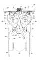
【図1】本発明の一実施形態に係る商品収納払出装置を備えた自動販売機の正面図である。
【図2】自動販売機の収納庫内に収容された商品ラックを示す正面図である。
【図3】収納庫内の商品ラックおよび駆動機構を示す平面図である。
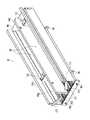
【図4】商品ラックの斜視図である。
【図5】ストッパの各ピニオンギアと各ラックギアの位置関係を示す斜視図である。
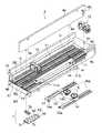
【図6】商品払出機構の構成を示す商品ラックの一部を破断した分解斜視図である。
【図7】ストッパの斜視図である。
【図8】商品払出機構の動作を示す模式図であり、(a)ベース板が保持位置にある状態と、(b)ベース板が払出位置に移動した状態と、(c)ベース板が保持位置に戻った状態をそれぞれ示している。
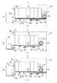
【図9】商品ラックが(a)棚板上の収容位置にある状態と、(b)ローディング時などに収容位置から引き出された状態をそれぞれ示す側面図である。
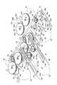
【図10】連結機構の構成を示す斜視図である。
【図11】連結機構の構成を示す平面図である。
【図12】連結機構の第2ギアが第1ギアと噛み合う第2角度まで時計回りに回転した状態を示す平面図である。
【図13】図12の状態から、第2ギアが時計回りに回転することによって、商品払出機構のスライド板が移動量L1だけ前方に移動した状態を示す平面図である。
【図14】図13の状態から第2ギアがさらに時計回りに回転した状態を示す平面図である。
【符号の説明】
1 商品収納払出装置
2 自動販売機
4 商品ラック
4a 側壁
4f 商品通路
4g 払出口
7 ベース板ストッパ
11 ベース板
12 ストッパ
12d レバー(第1阻止部材)
13 開閉板
CL ワンウェイクラッチ(第2阻止部材)
P1 第1ピニオンギア
P2 第2ピニオンギア
R1 第1ラックギア
R2 第2ラックギア
S 商品
S1 商品
S2 商品
Sx 販売商品[0001]
BACKGROUND OF THE INVENTION
The present invention is a type of automatic machine that stores a large number of products side by side in the front-rear direction, such as a so-called see-through type vending machine that can visually recognize products that are actually sold, and pays the products forward or backward at the time of sale. The present invention relates to a product storage / dispensing device for a vending machine.
[0002]
[Prior art]
The applicant has already proposed such a commodity storage / dispensing device in Japanese Patent Application No. 9-69210. This product storage / dispensing device is arranged in a vertical direction in the vending machine main body, a number of shelf boards fixed to the vending machine main body, a plurality of product racks mounted on each shelf board, and And an elevator that can be raised and lowered forward and can receive products from each product rack. Each product rack has a product passage that can store a large number of products in a horizontal direction, an opening / closing plate that is arranged near the payout opening of the product passage and opens and closes the payout opening, and a spring or other biasing force. And a pusher that always presses the opening / closing plate side. In the vending machine body, a drive mechanism for driving the opening / closing plate of the product rack is attached to each product rack.
[0003]
In the product storage / dispensing device, the opening / closing plate is positioned at a home position for closing the payout opening and holds a product row arranged in the front-rear direction between the pusher when the product is on sale. At the time of sales, the elevator first moves to a predetermined position near the outlet of the product rack to which the product is to be delivered and stops. Thereafter, the drive mechanism rotates the opening / closing plate from the home position to a predetermined angle that opens the payout opening, thereby opening the payout opening. As a result, the product row in the product passage is pushed forward by the pusher, and only the product at the foremost position is delivered forward from the delivery outlet. The paid-out merchandise is received by the elevator and conveyed to the sales port below. After the product is dispensed, the opening / closing plate is rotated in the reverse direction to return to the home position.
[0004]
[Problems to be solved by the invention]
According to the conventional product storage / dispensing device, the product row arranged in the product passage is pushed forward by the pusher at the time of sale, so the pusher's pressing force is such that the maximum number of product rows can be stored in the product passage. It is set to be larger than the frictional force generated between the bottom and the bottom. When waiting for sale, this large pressing force is always applied to the product line in the product passage, so in the case of a product made of a soft material container, the container may be deformed or damaged. For this reason, there may be cases where the product is not paid out smoothly when the product is sold. In addition, in the case of a product having a shape in which the pressing force of the pusher does not easily act on the side surface of each product, for example, a product having a shape in which the diameter gradually increases or decreases toward the upper side of the container, the product rack When a product is paid out, the arrangement of the product rows is likely to be disturbed, and stacking or catching may occur, and the product may not be paid out smoothly.
[0005]
The present invention was made in order to solve the above-mentioned problem, in a product storage / dispensing device of a vending machine of a type that stores a large number of products side by side in the front-rear direction and pays out the product in one of the front-rear directions at the time of sale. It is an object of the present invention to provide a commodity storage / dispensing device capable of dispensing a commodity reliably and stably.
[0006]
[Means for Solving the Problems]
A product storage / dispensing device for a vending machine according to
[0007]
According to the product storage / dispensing device of this vending machine, when the base plate moves from the standby position to the payout position when the product is sold, the stopper is locked to the base plate by the first locking means. A plurality of products are placed on the base plate at the bottom of the product passage and move together with the base plate while being held by the stopper without falling in the direction opposite to the moving direction in contact with the stopper. . Thereafter, when the base plate returns to the standby position after reaching the payout position, the stopper is locked to the product rack by the second locking means, and is independent of the movement of the base plate. As a result, the stored product is prevented from moving by the stopper locked to the product rack regardless of the movement of the base plate. To be paid out.
[0008]
In this way, at the time of sale, the product is placed on the base plate and carried to the dispensing position in a state where the posture is held by the stopper. Unlike conventional products, the product of the container made of a soft material and the force Even a product with a shape that does not easily act on the side surface can be transported to a dispensing position in a stable state and smoothly dispensed without causing a disturbance in the product row. In addition to this, unlike conventional product storage / dispensing devices, the pressing force of the stopper that acts on the product to pay out the product works only when the product is paid out, and the number of stored products as the sales progress. As the pressure decreases, the applied pressing force gradually decreases. As a result, even a container product made of a softer material than before can be stored and dispensed without causing deformation or breakage.
[0009]
In the above, it is preferable to further include an adjusting means for adjusting the amount of movement when the base plate moves between the standby position and the payout position.
[0010]
According to the commodity storage / dispensing device of this vending machine, the movement amount of the base plate can be adjusted in accordance with the depth of the commodity. Thus, for example, if the amount of movement is approximately the same as the depth of the product, when the base plate moves to the payout position and then returns to the standby position, the product located most outward from the payout outlet is When the base plate is removed from the entire bottom, the base plate is paid out in an almost unchanged posture. In this way, the product can be paid out in an almost unchanged posture, and can be paid out more reliably and stably.
[0011]
In the above, the adjusting means is selectively attached to a plurality of positions in the front-rear direction in a stationary relationship with respect to the product rack, and the base plate abuts at the payout position when the base plate moves to the payout position side. It is preferable that it is composed of a plate stopper.
[0012]
According to the commodity storage / dispensing device of this vending machine, since the base plate stopper is immovable with respect to the commodity rack, the base plate is surely stopped by coming into contact with it at the dispensing position. Since this base plate stopper can be selectively attached at a plurality of positions in the front-rear direction, the amount of movement of the base plate to the payout position can be appropriately changed in the front-rear direction according to the depth of the product.
[0013]
Further, in the above, the outlet is provided so as to be openable and closable, and by closing the outlet when the product is on sale, a plurality of products are held between the stoppers, and the outlet is opened when the item is sold. It is preferable to further include an opening / closing plate.
[0014]
According to the product storage / dispensing device of the vending machine, the opening / closing plate closes the outlet when the product is on sale, so that the product in the product passage is held between the opening / closing plate and the stopper, thereby There will be no accidental withdrawal from the exit. At the time of sale, the opening / closing plate opens the payout opening, so that the product can be paid out and sold as described above. As a result, the product can be sold reliably.
[0015]
In the above, the base plate is formed with the first rack gear extending in the front-rear direction, the product rack is formed with the second rack gear extending in the front-rear direction, and the locking means is the first rack gear of the base plate. A first pinion gear that meshes with the base plate, a first blocking member that blocks rotation of the first gear when the base plate moves toward the payout position, a second pinion gear that meshes with the second rack gear of the product rack, and a base plate It is preferable to include a second blocking member that blocks rotation of the second pinion gear when moving to the standby position side.
[0016]
According to the product storage / dispensing device of this vending machine, the base plate and the product rack are each provided with a rack gear, and the stopper is provided with two sets of pinion gears and a blocking member. Realizes a structure in which the locking plate is securely locked to the base plate when the base plate is moved to the payout position, and is securely locked to the product rack when the base plate is moved to the standby position. can do. Thereby, as described above, a structure for paying out a product in a stable state can be realized at low cost.
[0017]
DETAILED DESCRIPTION OF THE INVENTION
Hereinafter, a product storage / dispensing device for a vending machine according to an embodiment of the present invention will be described with reference to the accompanying drawings. Details of each part of the present invention will be described later. First, a schematic configuration and an operation thereof will be described. As shown in FIGS. 1 to 8, in the product storage /
[0018]
As shown in FIGS. 3 and 10, the
[0019]
In the product storage /
[0020]
Next, the product storage /
[0021]
As shown in FIGS. 1 to 3, the two
The desired product S is purchased by inputting with the product selection button 3e.
[0022]
The one-stage (four left and right)
[0023]
As shown in FIGS. 4 to 6, the
[0024]
When attaching the
[0025]
As shown in FIGS. 5 and 6, two third rack gears R3 and R3 are formed symmetrically on the upper surface of the bottom wall 4b with the
[0026]
The
[0027]
As shown in FIGS. 5 and 6, a first rack gear R <b> 1 extending in the front-rear direction similar to the rack gears R <b> 2 and R <b> 3 is formed at the center of the upper surface of the
[0028]
As shown in FIG. 6, the
[0029]
Accordingly, the abutting
[0030]
As shown in FIG. 7, the
[0031]
The first pinion gear P1 is disposed at the center of the
[0032]
The second pinion gear P2 is attached to the right end of the
[0033]
As shown in FIGS. 5 and 6, the second pinion gear P2 and the third pinion gear P3 are arranged such that the second rack gear R2 and the third rack gear R3 that engage with each other are arranged vertically, so that the
[0034]
In the
[0035]
As shown in FIG. 8C, when the
[0036]
For example, when loading the product S, the
[0037]
By this movement, the third pinion gear P3 is disengaged from the
[0038]
As shown in FIG. 4, the open /
[0039]
As shown in FIGS. 6 and 10, the
[0040]
The small-
[0041]
As shown in FIG. 6, a
[0042]
The
[0043]
As shown in FIG. 9, two
[0044]
The
[0045]
As shown in FIGS. 6 and 9, two
[0046]
As shown in FIG. 8, an
[0047]
As shown in FIGS. 3, 9 and 10, the
[0048]
As shown in FIGS. 3 and 10, on the
[0049]
The
[0050]
As shown in FIGS. 10 and 11, a
[0051]
The
[0052]
When the
[0053]
A heart-shaped
[0054]
During the forward / reverse rotation, the
[0055]
The
[0056]
The operation at the time of sale of the product S of the product storage /
[0057]
After the
[0058]
That is, when the
[0059]
Thereafter, when the
[0060]
As a result, when the
[0061]
In addition, the product S1 stored in the
[0062]
As described above in detail, according to the product storage /
[0063]
Further, unlike the prior art, the pressing force for paying out the product S only acts when the product S abuts against the
[0064]
Further, since the abutting
[0065]
Further, since the
[0066]
In the embodiment described above, the
[0067]
Moreover, in the said embodiment, although the
[0068]
【The invention's effect】
As described above, according to the product storage / dispensing device of the vending machine of the present invention, in a product storage / dispensing device of a type that stores a large number of products arranged in the front-rear direction, and pays out the product in one of the front-rear directions at the time of sale The product can be paid out in a stable state.
[Brief description of the drawings]
FIG. 1 is a front view of a vending machine provided with a product storage / dispensing device according to an embodiment of the present invention.
FIG. 2 is a front view showing a product rack stored in a storage of the vending machine.
FIG. 3 is a plan view showing a product rack and a drive mechanism in the storage.
FIG. 4 is a perspective view of a product rack.
FIG. 5 is a perspective view showing a positional relationship between each pinion gear of the stopper and each rack gear.
FIG. 6 is an exploded perspective view in which a part of a product rack showing a configuration of the product delivery mechanism is broken.
FIG. 7 is a perspective view of a stopper.
FIGS. 8A and 8B are schematic diagrams showing the operation of the product dispensing mechanism, in which (a) the base plate is in the holding position, (b) the base plate is moved to the dispensing position, and (c) the base plate is held. Each of the states returned to the position is shown.
FIGS. 9A and 9B are side views respectively showing a state in which the product rack is in the storage position on the shelf board and a state in which the product rack is pulled out from the storage position during loading or the like.
FIG. 10 is a perspective view showing a configuration of a coupling mechanism.
FIG. 11 is a plan view showing a configuration of a coupling mechanism.
FIG. 12 is a plan view showing a state in which the second gear of the coupling mechanism is rotated clockwise to a second angle meshing with the first gear.
13 is a plan view showing a state in which the slide plate of the commodity dispensing mechanism has moved forward by a movement amount L1 as the second gear rotates clockwise from the state of FIG. 12;
14 is a plan view showing a state in which the second gear is further rotated clockwise from the state of FIG. 13;
[Explanation of symbols]
1 Commodity storage / dispensing device
2 Vending machines
4 Product rack
4a side wall
4f product passage
4g outlet
7 Base plate stopper
11 Base plate
12 Stopper
12d lever (first blocking member)
13 Opening and closing plate
CL one-way clutch (second blocking member)
P1 1st pinion gear
P2 2nd pinion gear
R1 1st rack gear
R2 2nd rack gear
S product
S1 product
S2 product
Sx products for sale
Claims (5)
Translated fromJapaneseこの商品ラックの底部に設けられ、前記2つの側壁と共に複数の商品を前後方向に並べて収納するための商品通路を構成し、かつ前記商品ラックの前記払出口から外方に突出する払出位置と、内方に退避する待機位置との間で、前記商品ラックに対して前後方向に移動可能なベース板と、
このベース板の上面に設けられたストッパと、
前記ベース板の前記払出位置側への移動時には、前記ストッパを前記ベース板に係止させる第1係止手段と、
前記ベース板の前記待機位置側への移動時には、前記ストッパを前記商品ラックに係止させる第2係止手段と、
前記商品の販売待機時に、前記ベース板を前記待機位置に保持し、前記商品の販売時に、前記ベース板を前記払出位置に移動させた後、前記待機位置に移動させる駆動機構と、
を備えることを特徴とする自動販売機の商品収納払出装置。A product rack having two side walls opposed to each other and a payout port formed at one of the front and rear ends for paying out the product;
A payout position that is provided at the bottom of the product rack, forms a product passage for storing a plurality of products in the front-rear direction together with the two side walls, and projects outward from the payout opening of the product rack; A base plate that is movable in the front-rear direction with respect to the product rack between a standby position for retreating inward;
A stopper provided on the upper surface of the base plate;
A first locking means for locking the stopper to the base plate when the base plate is moved toward the payout position;
A second locking means for locking the stopper to the product rack when the base plate is moved to the standby position side;
A drive mechanism that holds the base plate in the standby position during the sale of the product, moves the base plate to the payout position, and then moves the base plate to the standby position during the sale of the product;
A product storage / dispensing device for a vending machine.
前記第1係止手段は、前記ベース板の前記第1ラックギアに噛み合う第1ピニオンギアと、前記ベース板の前記払出位置側への移動時に、前記第1ギアの回転を阻止する第1阻止部材とで構成され、
前記第2係止手段は、前記商品ラックの前記第2ラックギアに噛み合う第2ピニオンギアと、前記ベース板の前記待機位置側への移動時に、前記第2ピニオンギアの回転を阻止する第2阻止部材とで構成されていることを特徴とする請求項1乃至4のいずれかに記載の自動販売機の商品収納払出装置。A first rack gear extending in the front-rear direction is formed on the base plate, and a second rack gear extending in the front-rear direction is formed on the product rack,
The first locking means includes a first pinion gear that meshes with the first rack gear of the base plate, and a first blocking member that blocks rotation of the first gear when the base plate moves to the payout position side. And consists of
The second locking means includes a second pinion gear that meshes with the second rack gear of the commodity rack, and a second block that prevents rotation of the second pinion gear when the base plate moves to the standby position side. The product storage / dispensing device for a vending machine according to any one of claims 1 to 4, wherein the product storage / dispensing device is a member.
Priority Applications (2)
| Application Number | Priority Date | Filing Date | Title |
|---|---|---|---|
| JP06465598AJP3743153B2 (en) | 1998-02-26 | 1998-02-26 | Merchandise storage and dispensing device for vending machines |
| US09/378,511US6253954B1 (en) | 1998-02-26 | 1999-08-20 | Article storage/dispensing device for vending machine |
Applications Claiming Priority (2)
| Application Number | Priority Date | Filing Date | Title |
|---|---|---|---|
| JP06465598AJP3743153B2 (en) | 1998-02-26 | 1998-02-26 | Merchandise storage and dispensing device for vending machines |
| US09/378,511US6253954B1 (en) | 1998-02-26 | 1999-08-20 | Article storage/dispensing device for vending machine |
Publications (2)
| Publication Number | Publication Date |
|---|---|
| JPH11250341A JPH11250341A (en) | 1999-09-17 |
| JP3743153B2true JP3743153B2 (en) | 2006-02-08 |
Family
ID=26405755
Family Applications (1)
| Application Number | Title | Priority Date | Filing Date |
|---|---|---|---|
| JP06465598AExpired - Fee RelatedJP3743153B2 (en) | 1998-02-26 | 1998-02-26 | Merchandise storage and dispensing device for vending machines |
Country Status (2)
| Country | Link |
|---|---|
| US (1) | US6253954B1 (en) |
| JP (1) | JP3743153B2 (en) |
Families Citing this family (108)
| Publication number | Priority date | Publication date | Assignee | Title |
|---|---|---|---|---|
| DE19946609B4 (en)* | 1999-09-29 | 2005-08-11 | Deutsche Wurlitzer Gmbh | Vending machine with several superimposed goods compartments |
| US8627965B2 (en) | 2001-05-17 | 2014-01-14 | Rtc Industries, Inc. | Multi-component display and merchandise systems |
| US8096427B2 (en) | 2002-05-17 | 2012-01-17 | Rtc Industries, Inc. | Product management display system |
| US7931156B2 (en)* | 2001-05-17 | 2011-04-26 | Rtc Industries, Inc. | Product management display system with retaining wall |
| EP1395152B1 (en)* | 2001-05-17 | 2005-02-02 | Rtc Industries, Inc. | Product management display system |
| BE1014322A6 (en)* | 2001-07-31 | 2003-08-05 | New Distrib Systems Nv | Transport device for a distribution device for products. |
| WO2003072471A1 (en)* | 2001-11-23 | 2003-09-04 | Munroe Chirnomas | Machine and methods for vending articles |
| US6752277B1 (en)* | 2002-08-20 | 2004-06-22 | Masters Of Branding, Inc. | Product display system using radio frequency identification |
| GB2392667B (en)* | 2002-09-07 | 2004-11-03 | Nigel Francis Gamble | Pusher apparatus for merchandise |
| US20050040123A1 (en)* | 2003-08-22 | 2005-02-24 | Ala Ali | Inventory control system |
| US7222748B2 (en)* | 2003-09-26 | 2007-05-29 | Royal Vendors, Inc. | Clear door vending machine |
| US8047385B2 (en)* | 2004-02-03 | 2011-11-01 | Rtc Industries, Inc. | Product securement and management system |
| US8113601B2 (en) | 2004-02-03 | 2012-02-14 | Rtc Industries, Inc. | Product securement and management system |
| US8235222B2 (en)* | 2004-02-03 | 2012-08-07 | Rtc Industries, Inc. | Product securement and management system |
| US8938396B2 (en) | 2004-02-03 | 2015-01-20 | Rtc Industries, Inc. | System for inventory management |
| US11375826B2 (en)* | 2004-02-03 | 2022-07-05 | Rtc Industries, Inc. | Product securement and management system |
| US9375100B2 (en) | 2004-02-03 | 2016-06-28 | Rtc Industries, Inc. | Product securement and management system |
| US10339495B2 (en) | 2004-02-03 | 2019-07-02 | Rtc Industries, Inc. | System for inventory management |
| US9706857B2 (en) | 2004-02-03 | 2017-07-18 | Rtc Industries, Inc. | Product securement and management system |
| US7621409B2 (en) | 2004-02-03 | 2009-11-24 | Rtc Industries, Inc. | Product securement and management system |
| US7150365B2 (en) | 2004-02-03 | 2006-12-19 | Rtc Industries, Inc. | Product securement and management system |
| US9898712B2 (en) | 2004-02-03 | 2018-02-20 | Rtc Industries, Inc. | Continuous display shelf edge label device |
| US7404494B2 (en) | 2004-02-03 | 2008-07-29 | Rtc Industries, Inc. | Kinetic inertial delivery system |
| US7792711B2 (en)* | 2004-02-03 | 2010-09-07 | Rtc Industries, Inc. | System for inventory management |
| US7451881B2 (en) | 2004-02-03 | 2008-11-18 | Rtc Industries, Inc. | Product securement and management system |
| US9818148B2 (en) | 2013-03-05 | 2017-11-14 | Rtc Industries, Inc. | In-store item alert architecture |
| EP1763851A4 (en)* | 2004-02-27 | 2011-11-30 | Sandenvendo America Inc | Vending machine and component parts |
| US7837059B2 (en)* | 2004-02-27 | 2010-11-23 | Sanden Vendo America, Inc. | Product acquisition devices and methods for vending machines |
| US8162174B2 (en)* | 2004-02-27 | 2012-04-24 | Sandenvendo America, Inc. | Retrieval systems for vending machines |
| US7367472B2 (en)* | 2004-03-24 | 2008-05-06 | Anton K Simson | Pneumatic vending machine |
| US7404501B2 (en)* | 2004-05-14 | 2008-07-29 | Dixie-Narco, Inc. | Product positioning mechanism for a vending machine |
| DE102004031699B4 (en)* | 2004-06-30 | 2007-01-11 | Airbus Deutschland Gmbh | Goods dispensing system for an aircraft |
| US7347335B2 (en)* | 2005-01-21 | 2008-03-25 | Vulcan Spring & Manufacturing Company | Pusher assembly, merchandise dispenser and method of dispensing merchandise |
| NL1028378C2 (en)* | 2005-02-23 | 2006-08-24 | Hendrikus Johannes Hermanus Ke | Device for delivering a selected item. |
| ES2277517B1 (en)* | 2005-05-18 | 2008-06-01 | Jofermar, S.A. | UNIT EXTRACTOR SYSTEM OF THE PRODUCT IN EXPENDING MACHINES. |
| US7828158B2 (en) | 2005-07-14 | 2010-11-09 | Displays Plus, Inc. | Merchandise dispensing apparatus providing theft deterrence |
| US8312999B2 (en) | 2005-09-12 | 2012-11-20 | Rtc Industries, Inc. | Product management display system with trackless pusher mechanism |
| US9060624B2 (en) | 2005-09-12 | 2015-06-23 | Rtc Industries, Inc. | Product management display system with rail mounting clip |
| US11583109B2 (en) | 2005-09-12 | 2023-02-21 | Rtc Industries, Inc. | Product management display system with trackless pusher mechanism |
| US9265358B2 (en) | 2005-09-12 | 2016-02-23 | RTC Industries, Incorporated | Product management display system |
| US10285510B2 (en) | 2005-09-12 | 2019-05-14 | Rtc Industries, Inc. | Product management display system |
| US8453850B2 (en) | 2005-09-12 | 2013-06-04 | Rtc Industries, Inc. | Product management display system with trackless pusher mechanism |
| US8967394B2 (en) | 2005-09-12 | 2015-03-03 | Rtc Industries, Inc. | Product management display system with trackless pusher mechanism |
| US7823734B2 (en) | 2005-09-12 | 2010-11-02 | Rtc Industries, Inc. | Product management display system with trackless pusher mechanism |
| US9173504B2 (en) | 2005-09-12 | 2015-11-03 | Rtc Industries, Inc. | Product management display system |
| US9259102B2 (en) | 2005-09-12 | 2016-02-16 | RTC Industries, Incorporated | Product management display system with trackless pusher mechanism |
| US9486088B2 (en) | 2005-09-12 | 2016-11-08 | Rtc Industries, Inc. | Product management display system |
| US9750354B2 (en) | 2005-09-12 | 2017-09-05 | Rtc Industries, Inc. | Product management display system |
| US11259652B2 (en)* | 2005-09-12 | 2022-03-01 | Rtc Industries, Inc. | Product management display system |
| US8863963B2 (en) | 2005-09-12 | 2014-10-21 | Rtc Industries, Inc. | Product management display system with trackless pusher mechanism |
| US9232864B2 (en) | 2005-09-12 | 2016-01-12 | RTC Industries, Incorporated | Product management display system with trackless pusher mechanism |
| US9265362B2 (en) | 2005-09-12 | 2016-02-23 | RTC Industries, Incorporated | Product management display system |
| US10952546B2 (en) | 2005-09-12 | 2021-03-23 | Rtc Industries, Inc. | Product management display system with trackless pusher mechanism |
| US11344138B2 (en) | 2005-09-12 | 2022-05-31 | Rtc Industries, Inc. | Product management display system |
| US9138075B2 (en) | 2005-09-12 | 2015-09-22 | Rtc Industries, Inc. | Product management display system |
| US8739984B2 (en) | 2005-09-12 | 2014-06-03 | Rtc Industries, Inc. | Product management display system with trackless pusher mechanism |
| US8978904B2 (en) | 2005-09-12 | 2015-03-17 | Rtc Industries, Inc. | Product management display system with trackless pusher mechanism |
| US7784644B2 (en)* | 2005-10-14 | 2010-08-31 | Dixie-Narco, Inc. | Tandem gate release mechanism for a vending machine |
| US7837058B2 (en)* | 2005-10-14 | 2010-11-23 | Crane Merchandising Systems, Inc. | Product transport system for a vending machine |
| US7604145B2 (en) | 2005-10-14 | 2009-10-20 | Dixie-Narco, Inc. | Drive system for a vending machine dispensing assembly |
| US7497342B2 (en)* | 2005-10-25 | 2009-03-03 | Rtc Industries, Inc. | Product management display system |
| US7628282B2 (en) | 2005-10-25 | 2009-12-08 | Rtc Industries, Inc. | Product management display system |
| US20070235468A1 (en)* | 2006-04-10 | 2007-10-11 | Robert Liva | Programmable helical coil dispensing system |
| US20070262083A1 (en)* | 2006-05-12 | 2007-11-15 | Coca-Cola Enterprises Inc. | Vending machine with non-vend storage area and modular storage unit |
| WO2008051996A2 (en) | 2006-10-23 | 2008-05-02 | Rtc Industries, Inc. | Merchandising system with flippable column |
| US8622227B2 (en) | 2007-01-16 | 2014-01-07 | Fasteners For Retail, Inc. | Merchandise security system |
| WO2008088789A2 (en) | 2007-01-16 | 2008-07-24 | Fasteners For Retail, Inc. | Merchandise security system |
| ES2277802B2 (en)* | 2007-03-16 | 2008-04-16 | Jofemar S.A. | UNIT EXTRACTOR SYSTEM OF PRODUCTS FOR EXPENDING MACHINES. |
| EP2390849B1 (en)* | 2007-05-16 | 2014-07-30 | Sanden Corporation | Commodity carrying out device |
| JP5013972B2 (en)* | 2007-05-31 | 2012-08-29 | サンデン株式会社 | Vending machine product column |
| FR2928141A1 (en)* | 2008-02-28 | 2009-09-04 | Oscaro Com Sa | SPARE PARTS STORE AND METHOD FOR ASSIGNING LOTS OF SPARE PARTS. |
| ITTO20080367A1 (en)* | 2008-05-15 | 2009-11-16 | N&W Global Vending Spa | METHOD AND AUTOMATIC DISTRIBUTOR FOR THE DISTRIBUTION OF PRODUCTS |
| US8016128B2 (en)* | 2008-07-16 | 2011-09-13 | Southern Imperial, Inc. | Wheeled pusher system |
| IT1392961B1 (en)* | 2009-01-20 | 2012-04-02 | N&W Global Vending S P A | TRAY FOR AUTOMATIC PRODUCT DISTRIBUTORS |
| US8678232B2 (en) | 2009-08-27 | 2014-03-25 | Utique, Inc. | Inventory storage and dispensing mechanism |
| US8392019B2 (en)* | 2009-08-27 | 2013-03-05 | Utique, Inc. | Modular vending with centralized robotic gantry |
| US8620472B2 (en)* | 2009-08-27 | 2013-12-31 | Utique, Inc. | Dispensing mechanism for centralized robotic gantry |
| US20120103922A1 (en)* | 2010-11-02 | 2012-05-03 | Fasteners For Retail, Inc. | Product merchandiser |
| US9640014B2 (en)* | 2011-01-04 | 2017-05-02 | Fawn Engineering Corporation | Vending machine with elevator delivery of vended product to customer access |
| KR101592799B1 (en)* | 2011-11-14 | 2016-02-05 | 후지 덴키 가부시키가이샤 | Vending machine |
| KR101974684B1 (en)* | 2012-05-30 | 2019-05-02 | 후지 덴키 가부시키가이샤 | Product housing device |
| US9357856B2 (en) | 2012-08-03 | 2016-06-07 | Fasteners For Retail, Inc. | Latching system for a merchandising apparatus |
| US9451836B2 (en) | 2012-08-03 | 2016-09-27 | Fasteners For Retail, Inc. | Sliding and pivoting retainer |
| CN103871167B (en)* | 2012-12-11 | 2016-08-03 | 安徽九丁智能科技有限责任公司 | Automatic vending machine |
| US10357118B2 (en) | 2013-03-05 | 2019-07-23 | Rtc Industries, Inc. | Systems and methods for merchandizing electronic displays |
| US9433305B2 (en) | 2013-03-15 | 2016-09-06 | Fasteners For Retail, Inc. | Product merchandiser |
| US9427095B2 (en)* | 2013-04-03 | 2016-08-30 | Fasteners For Retail, Inc. | Anti-tip guide for product merchandiser |
| US10154739B2 (en) | 2013-12-02 | 2018-12-18 | Retail Space Solutions Llc | Universal merchandiser and methods relating to same |
| USD801734S1 (en) | 2014-12-01 | 2017-11-07 | Retail Space Solutions Llc | Shelf management parts |
| US9320367B2 (en) | 2014-02-26 | 2016-04-26 | Southern Imperial, Inc. | Snap-in pusher |
| US9870671B1 (en) | 2014-04-07 | 2018-01-16 | Fawn Engineering Corporation | Mechanical lift for delivery bins in vending machines |
| US11109692B2 (en) | 2014-11-12 | 2021-09-07 | Rtc Industries, Inc. | Systems and methods for merchandizing electronic displays |
| US11182738B2 (en) | 2014-11-12 | 2021-11-23 | Rtc Industries, Inc. | System for inventory management |
| JP2016118911A (en)* | 2014-12-19 | 2016-06-30 | サンデンホールディングス株式会社 | Automatic dispenser |
| US9955802B2 (en) | 2015-04-08 | 2018-05-01 | Fasteners For Retail, Inc. | Divider with selectively securable track assembly |
| MX394155B (en)* | 2015-12-29 | 2025-03-24 | Xiaoyu Guo | PALLET MOVEMENT SYSTEM FOR PALLET STORAGE ASSEMBLY. |
| WO2017123988A1 (en) | 2016-01-13 | 2017-07-20 | Rtc Industries, Inc. | Merchandise display system with an anti-splay device |
| US10055928B1 (en)* | 2016-04-11 | 2018-08-21 | Fawn Engineering Corporation | Highly adjustable push-type dispensing module for dispensing items |
| US10332331B2 (en) | 2016-10-14 | 2019-06-25 | Pepsico, Inc. | Modular vending machine |
| US10959540B2 (en) | 2016-12-05 | 2021-03-30 | Retail Space Solutions Llc | Shelf management system, components thereof, and related methods |
| US10490014B2 (en) | 2016-12-16 | 2019-11-26 | Pepsico, Inc. | Lean vending machine |
| WO2018200997A1 (en) | 2017-04-27 | 2018-11-01 | Retail Space Solutions Llc | Shelf-mounted tray and methods relating to same |
| CN113679209A (en) | 2017-06-16 | 2021-11-23 | Rtc工业股份有限公司 | Product management display system with trackless pusher mechanism |
| US11045016B2 (en)* | 2018-12-20 | 2021-06-29 | Process Retail Group, Inc. | Bearing pusher assembly, and product display including a bearing pusher assembly |
| JP2024505661A (en)* | 2021-02-02 | 2024-02-07 | ペプシコ・インク | Product release mechanism and vending machine with product release mechanism |
| WO2022245874A1 (en)* | 2021-05-18 | 2022-11-24 | Bruegmann USA, Inc. | Product merchandise display with resilient product package retainer |
| CN113240854A (en)* | 2021-06-16 | 2021-08-10 | 成都大呱呱科技有限公司 | Novel automatic vending equipment |
| US12262823B1 (en)* | 2024-02-06 | 2025-04-01 | Henschel-Steinau, Inc. | Theft deterrent slide down door assembly for a merchandise display |
Family Cites Families (1)
| Publication number | Priority date | Publication date | Assignee | Title |
|---|---|---|---|---|
| US2632681A (en)* | 1949-06-30 | 1953-03-24 | City Vending Equipment Corp | Article handling machine |
- 1998
- 1998-02-26JPJP06465598Apatent/JP3743153B2/ennot_activeExpired - Fee Related
- 1999
- 1999-08-20USUS09/378,511patent/US6253954B1/ennot_activeExpired - Fee Related
Also Published As
| Publication number | Publication date |
|---|---|
| JPH11250341A (en) | 1999-09-17 |
| US6253954B1 (en) | 2001-07-03 |
Similar Documents
| Publication | Publication Date | Title |
|---|---|---|
| JP3743153B2 (en) | Merchandise storage and dispensing device for vending machines | |
| JP4936576B1 (en) | Manual product sales equipment | |
| CN203455894U (en) | Commodity storage device | |
| JP3719363B2 (en) | Vending machine product dispensing device | |
| JP3524780B2 (en) | Vending machine product unloading device | |
| CN203616815U (en) | Commodity storing device | |
| JP2019023897A (en) | Manual commodity-selling device | |
| JP3508902B2 (en) | Vending machine product delivery device | |
| JPH11250343A (en) | Commodity storage pay-out device for automatic vending machine | |
| JP2013149229A (en) | Manual commodity-selling device | |
| JP3524777B2 (en) | Vending machine product unloading device | |
| JP3811577B2 (en) | Vending machine product dispensing device | |
| JP2000259941A (en) | Merchandise housing and ejecting device for automatic vending machine | |
| JP3475093B2 (en) | Vending machine product unloading device | |
| JP4058939B2 (en) | Vending machine product unloading device | |
| JP2017084424A (en) | Manual product sales equipment | |
| JPH11154269A (en) | vending machine | |
| JP3561638B2 (en) | Vending machine product unloading device | |
| JP2004005186A (en) | Vending machine product unloading device | |
| JP3969420B2 (en) | vending machine | |
| JP3561662B2 (en) | Vending machine product storage device | |
| JP2000076532A (en) | Product storing and ejecting device | |
| JP2001184555A (en) | Article carrying-out device for automatic vending machine | |
| JP4007449B2 (en) | vending machine | |
| JP2000123239A (en) | Commodity receiving/paying-out device of automatic vending machine |
Legal Events
| Date | Code | Title | Description |
|---|---|---|---|
| A621 | Written request for application examination | Free format text:JAPANESE INTERMEDIATE CODE: A621 Effective date:20040415 | |
| A977 | Report on retrieval | Free format text:JAPANESE INTERMEDIATE CODE: A971007 Effective date:20051021 | |
| TRDD | Decision of grant or rejection written | ||
| A01 | Written decision to grant a patent or to grant a registration (utility model) | Free format text:JAPANESE INTERMEDIATE CODE: A01 Effective date:20051025 | |
| A61 | First payment of annual fees (during grant procedure) | Free format text:JAPANESE INTERMEDIATE CODE: A61 Effective date:20051107 | |
| R150 | Certificate of patent or registration of utility model | Free format text:JAPANESE INTERMEDIATE CODE: R150 | |
| FPAY | Renewal fee payment (event date is renewal date of database) | Free format text:PAYMENT UNTIL: 20091125 Year of fee payment:4 | |
| FPAY | Renewal fee payment (event date is renewal date of database) | Free format text:PAYMENT UNTIL: 20091125 Year of fee payment:4 | |
| FPAY | Renewal fee payment (event date is renewal date of database) | Free format text:PAYMENT UNTIL: 20101125 Year of fee payment:5 | |
| FPAY | Renewal fee payment (event date is renewal date of database) | Free format text:PAYMENT UNTIL: 20111125 Year of fee payment:6 | |
| FPAY | Renewal fee payment (event date is renewal date of database) | Free format text:PAYMENT UNTIL: 20121125 Year of fee payment:7 | |
| FPAY | Renewal fee payment (event date is renewal date of database) | Free format text:PAYMENT UNTIL: 20121125 Year of fee payment:7 | |
| S531 | Written request for registration of change of domicile | Free format text:JAPANESE INTERMEDIATE CODE: R313531 | |
| FPAY | Renewal fee payment (event date is renewal date of database) | Free format text:PAYMENT UNTIL: 20121125 Year of fee payment:7 | |
| R350 | Written notification of registration of transfer | Free format text:JAPANESE INTERMEDIATE CODE: R350 | |
| FPAY | Renewal fee payment (event date is renewal date of database) | Free format text:PAYMENT UNTIL: 20131125 Year of fee payment:8 | |
| FPAY | Renewal fee payment (event date is renewal date of database) | Free format text:PAYMENT UNTIL: 20131125 Year of fee payment:8 | |
| S111 | Request for change of ownership or part of ownership | Free format text:JAPANESE INTERMEDIATE CODE: R313111 | |
| FPAY | Renewal fee payment (event date is renewal date of database) | Free format text:PAYMENT UNTIL: 20131125 Year of fee payment:8 | |
| R350 | Written notification of registration of transfer | Free format text:JAPANESE INTERMEDIATE CODE: R350 | |
| R250 | Receipt of annual fees | Free format text:JAPANESE INTERMEDIATE CODE: R250 | |
| LAPS | Cancellation because of no payment of annual fees |