JP3741014B2 - Control method and compressor system for a plurality of compressors - Google Patents
Control method and compressor system for a plurality of compressorsDownload PDFInfo
- Publication number
- JP3741014B2 JP3741014B2JP2001282573AJP2001282573AJP3741014B2JP 3741014 B2JP3741014 B2JP 3741014B2JP 2001282573 AJP2001282573 AJP 2001282573AJP 2001282573 AJP2001282573 AJP 2001282573AJP 3741014 B2JP3741014 B2JP 3741014B2
- Authority
- JP
- Japan
- Prior art keywords
- compressor
- compressors
- flow rate
- surge
- load
- Prior art date
- Legal status (The legal status is an assumption and is not a legal conclusion. Google has not performed a legal analysis and makes no representation as to the accuracy of the status listed.)
- Expired - Fee Related
Links
Images


Classifications
- F—MECHANICAL ENGINEERING; LIGHTING; HEATING; WEAPONS; BLASTING
- F04—POSITIVE - DISPLACEMENT MACHINES FOR LIQUIDS; PUMPS FOR LIQUIDS OR ELASTIC FLUIDS
- F04D—NON-POSITIVE-DISPLACEMENT PUMPS
- F04D27/00—Control, e.g. regulation, of pumps, pumping installations or pumping systems specially adapted for elastic fluids
- F04D27/02—Surge control
- F04D27/0207—Surge control by bleeding, bypassing or recycling fluids
- F—MECHANICAL ENGINEERING; LIGHTING; HEATING; WEAPONS; BLASTING
- F01—MACHINES OR ENGINES IN GENERAL; ENGINE PLANTS IN GENERAL; STEAM ENGINES
- F01D—NON-POSITIVE DISPLACEMENT MACHINES OR ENGINES, e.g. STEAM TURBINES
- F01D17/00—Regulating or controlling by varying flow
- F01D17/02—Arrangement of sensing elements
- F01D17/04—Arrangement of sensing elements responsive to load
- F—MECHANICAL ENGINEERING; LIGHTING; HEATING; WEAPONS; BLASTING
- F01—MACHINES OR ENGINES IN GENERAL; ENGINE PLANTS IN GENERAL; STEAM ENGINES
- F01D—NON-POSITIVE DISPLACEMENT MACHINES OR ENGINES, e.g. STEAM TURBINES
- F01D17/00—Regulating or controlling by varying flow
- F01D17/02—Arrangement of sensing elements
- F01D17/08—Arrangement of sensing elements responsive to condition of working-fluid, e.g. pressure
Landscapes
- Engineering & Computer Science (AREA)
- Mechanical Engineering (AREA)
- General Engineering & Computer Science (AREA)
- Life Sciences & Earth Sciences (AREA)
- Sustainable Development (AREA)
- Control Of Positive-Displacement Air Blowers (AREA)
Description
Translated fromJapanese【0001】
【発明の属する技術分野】
本発明は、複数台の圧縮機を並列に接続した複数台の圧縮機の制御方法および圧縮機システムに関する。
【0002】
【従来の技術】
複数台の圧縮機を並列に接続した圧縮機システムの例が、特開2000−120583号公報に記載されている。この公報では、運転圧縮機供給流量の最大値の和が負荷需要流量以上で、かつ運転圧縮機の台数が最小となるように、負荷需要流量を複数の流量調整範囲に区分している。それとと共に、各流量調整範囲ごとに運転圧縮機の組合せと運転圧縮機の制御状態を示す流量制御パターンを設定し、この設定パターンにしたがって各圧縮機を制御している。オン・オフ制御しかできない圧縮機が含まれているときは、定風圧制御とオン・オフ制御の双方が可能な圧縮機が流量調整機に設定される。この圧縮機に設定された流量の設定範囲に隣り合う範囲については、オン・オフ制御しかできない圧縮機を優先的に流量調整機としている。これにより、無負荷運転時の無駄を少なくできると共に、同時に複数の圧縮機がサージ待機状態となることを極力回避することが可能にしている。
【0003】
【発明が解決しようとする課題】
上記公報に記載された複数の圧縮機の制御方法においては、複数台の圧縮機の各々について流量特性を定め、その特性に基づいて予め設定した流量制御パターンを用いて各圧縮機を制御している。しかしながら、圧縮機装置内部が汚れる等の圧縮機の内部条件や、圧縮機に入る流体の温度や圧力が季節毎に変動する等の外部条件により、各圧縮機の実際の運転点が予想した運転点と異なる場合がある。その場合、予め設定された制御パターンを用いて圧縮機を制御しようとすると、予想より早く運転点がサージ限界に達したり、サージ限界よりだいぶ手前で圧縮機をアンロード運転させてしまうという事態が生じる。その結果、各圧縮機が無駄な動力を消費したり、思わぬサージの突入により圧縮機の運転が不安定になるという不具合を生じる恐れがあった。
【0004】
本発明は、上記従来の技術の不具合に鑑みなされたものであり、その目的は、複数台の圧縮機を有する圧縮機システムにおいて、簡単な制御システムににより部分負荷制御を容易にすることにある。本発明の他の目的は、複数台の圧縮機を有する圧縮機システムにおいて、消費動力を低減することにある。本発明のさらに他の目的は、運転条件が変動する状況においても、複数台の圧縮機を効果的に運転することにある。そして本発明はこれらいずれかの目的を少なくとも達成することを目的とする。
【0005】
【課題を解決するための手段】
上記目的を達成するための本発明の特徴は、並列接続された複数台のターボ圧縮機の制御方法であって、予め少なくとも1台の圧縮機のサージ限界を求めて記憶手段に記憶させ、複数台の圧縮機の負荷が減少したときに負荷運転している全圧縮機の流量を減少させ、最も早くサージに突入した圧縮機をアンロード運転させるとともにアンロード運転した圧縮機以外の圧縮機の流量を増大させて負荷に応じた運転を可能にし、負荷が減少して圧縮機の発生流量を低下させるときは、前記記憶手段に記憶されたサージ限界よりも所定量だけ大流量の点までは早く流量を低下させ、その後はサージを発生するサージ突入までそれまでよりゆっくりと流量を変化させ、すべての圧縮機が停止して再起動するときは、サージに突入してアンロード運転させたものから順に起動させることにある。
【0006】
上記目的を達成するための本発明の他の特徴は、並列接続された複数台のターボ圧縮機の制御方法であって、予め少なくとも1台の圧縮機のサージ限界を求めて記憶手段に記憶させ、複数台の圧縮機の負荷が減少したときに負荷運転している全圧縮機の流量を減少させ、最も早くサージに突入した圧縮機をアンロード運転させるとともにアンロード運転した圧縮機以外の圧縮機の流量を増大させて負荷に応じた運転を可能にし、負荷が減少して圧縮機の発生流量を低下させるときは、前記記憶手段に記憶されたサージ限界よりも所定量だけ大流量の点までは早く流量を低下させ、その後はサージを発生するサージ突入までそれまでよりゆっくりと流量を変化させ、アンロード運転している圧縮機が複数台あるときに負荷が増大してアンロード運転の圧縮機をロード運転に戻すときは、サージに突入したのが早い順にロード運転させることにある。
【0007】
さらに、上記目的を達成する本発明の特徴は、並列に接続された複数台のターボ圧縮機を有する圧縮機システムであって、複数台の圧縮機の各々は吸込み側にインレットガイドベーンを、吐出側にサージ検出手段をそれぞれ有し、並列接続された複数の圧縮機の吐出側の接続位置よりも下流側に圧縮機システムの吐出圧力を検出する検出手段を設け、この圧縮機システムの負荷が減少したときに負荷運転中の圧縮機が3台以上あれば、全ての圧縮機のそれぞれの流量を減少させ、最初にサージに突入した圧縮機をアンロード運転させるとともにその他の圧縮機の流量を増大させるように各圧縮機を制御する制御手段を有し、この制御手段は前記吐出圧力の検出手段が検出した吐出圧力が所定圧力になるように前記各インレットガイドベーンに回転角度指令を与えることにある。
【0011】
【発明の実施の形態】
以下、図面を用いて本発明の複数台の圧縮機の制御方法の一実施例を説明する。図1は、複数台の圧縮機を並列に接続した圧縮機システムの模式図であり、図2は圧縮機を4台並列に接続したときの消費動力線図である。また、図3は圧縮機の性能線図の予測値と実測値の違いを示した図であり、図4は圧縮機に吸込まれるガスの吸込み条件による圧縮機性能の違いを示した図である。
【0012】
本実施例の圧縮機システムでは、図1に示したように4台の圧縮機A0、B0、C0、D0が並列に接続されている。そしてこの並列に接続された各圧縮機A0、B0、C0、D0を、圧縮機の制御装置10が制御している。各圧縮機A0、B0、C0、D0は小容量のターボ圧縮機であり、同じ型式、同じ容量のものである。各圧縮機は同一の構成となっているので、以下、圧縮機A0を例に取り説明する。圧縮機A0は、圧縮機本体60aを有している。圧縮機本体60aの吸込み側にはインレットガイドベーン(IGV)50aが設けられており、圧縮機本体60aに吸込まれる作動ガス量を調整する。インレットガイドベーン50aのさらに上流には、吸込み圧力Ps1を検出する圧力センサー20aと吸込み温度Ts1を検出する温度センサー30aが取付けられている。なお、インレットガイドベーン50aには、詳細を後述する制御装置10からの開度指令信号が信号ケーブル51aを介して入力される。
【0013】
圧縮機本体60aを回転駆動するために、駆動機40aが圧縮機本体60aの回転軸に接続されている。圧縮機本体60aの吐出側には配管74aが接続されており、配管74aには差圧計A1が取付けられている。差圧計A1は、配管74a内を流れる作動ガスの圧力変化を取り出すためのオリフィス71aと、このオリフィス71aに並列に設けられた逆止弁72aと、これらオリフィス71aと逆止弁72aに配管75aにより直列に接続された圧力センサー70aとを備えている。これにより、圧力センサー70aは、オリフィス71a前後の圧力が計測可能である。
【0014】
差圧計A1が検出した圧縮機本体60aの吐出圧力信号は、信号線52aを経由して制御装置10に入力される。差圧計A1の下流には分岐部76aが形成されており、分岐した配管77aには放風弁80aが取付けられている。放風弁80aには、制御装置10から、信号線53aを介して大気または図示しない他の貯ガス手段に圧縮ガスを放風する指示信号が送られる。一方、配管74aには逆止弁73aが取付けられている。逆止弁73aの下流側84で、各圧縮機A0〜D0から吐出された圧縮ガスがまとめられ、レシーバータンク85に圧縮ガスが蓄えられる。圧縮機システムの吐出圧力Pdは、吐出配管に介在させた圧力計90により検出される。この検出した圧力信号は、信号線54により制御装置10に送られる。
【0015】
以上が、圧縮機A0の構成である。圧縮機B0、C0、D0の構成も同様であるので、詳細は省略する。次に、制御装置10について説明する。制御装置10は、各圧縮機本体60a〜60dのサージ限界データを記憶する記憶手段11を有している。制御装置10には、差圧計A1、B1、…が検出した各圧縮機本体60a、60b、…の吐出圧情報と、圧縮機システムの吐出圧Pdの信号が入力されている。なお図示していないが、各圧縮機本体60a、60b、…の吸込み側に設けた温度センサー30a、30b、…と圧力センサー20a、20b、…の情報も入力されている。一方、制御装置10からは、各圧縮機A0、B0、…に、インレットガイドベーン50a、50b、…を回動させる指令や、放風弁80a、80b、…を開閉する指令が発令される。
【0016】
このように構成した本実施例の差圧計A1の動作について、詳述する。配管74aから差圧計A1に導かれた圧縮作動ガスの圧力は、逆止弁72aを通り圧力センサー70aに伝えられる。配管74aの圧力が上昇すると、逆止弁72aを通してすぐに圧力センサー70aにその圧力が伝わる。そのため、配管74aと圧力センサー70aとでは、圧力の差がほとんどない。
【0017】
これに対し、配管74aの圧力が下がると、逆止弁72aが働いて配管74aから配管75aにはオリフィス71a側の配管からしか圧力が伝わらない。その結果、配管75a側の圧力は圧力低下する前の圧力から徐々にしか降下しない。一方、配管74aの圧力は、圧縮機本体60aから吐出される圧縮ガスの圧力変動にすぐに対応して低下する。したがって、配管74aと配管75a間には、差圧が生じる。この差圧を、差圧計70aが検出し、制御装置にその情報が送られれる。
【0018】
次に、図1に示した複数台の圧縮機を有する圧縮機システムの運転制御方法を、図2を用いて説明する。図2で、最上段は圧縮機システムから吐出される流量の時間変化であり、その下の4段は各圧縮機A0〜D0から吐出される流量の時間変化である。4台の圧縮機すべてが負荷運転された状態から、負荷を減少させていく場合を例に取り説明する。100%負荷状態、言い換えれば100%流量で圧縮機システムを運転している状態を出発点とする。なお、圧力センサー90が検出した吐出圧力は、需要元に達したときの圧力が必要圧力より高くなる圧力であるものとする。
【0019】
需要元の圧縮ガスの使用量が減少し、制御装置10が負荷の減少を検出すると、制御装置は各圧縮機A0〜D0に流量を減少させるように指示する。具体的には、各圧縮機本体60a、60b、…が備えるインレットガイドベーン50a、50b、…にベーンを閉じる方向に回動させるように指示する。その結果、各圧縮機A0〜D0の流量が一斉に減少する。
【0020】
制御装置10が備える記憶手段11に記憶された各圧縮機本体60a、60b、…のサージ限界点の近くまでは、各インレットガイドベーンを50a、50b、…を、早い速度で回動する。これをαモードと呼ぶ。サージ限界点の近くになったら、インレットガイドベーン50a、50b、…の回動速度を、それまでの回動速度の1/5程度まで減速する。これをβモードと呼ぶ。
【0021】
βモードでインレットガイドベーン50a、50b、…を回動し続けているときに、圧縮機A0が備える圧力センサー70aが圧力変動を検出し、制御装置に圧力変動を入力したとする。この時点までに他の圧力センサー70b、…は圧力変動を検出していないので、最初に圧縮機A0の備える圧縮機本体60aがサージに突入したことが分かる。そこで、圧縮機本体60aの吐出側に設けた放風弁80aを開いて圧縮機本体の吐出側圧力を開放するとともに、インレットガイドベーン50aを全閉にして圧縮機本体60aの仕事を減らす。これをアンロード運転(γモード)と呼ぶ。このとき、記憶手段11に記憶されたインレットガイドベーン50aの角度を、サージに突入したときのインレットガイドベーン50aの角度で書き換える。
【0022】
圧縮機A0がアンロード運転になったので、圧縮機システムの流量は激減する。そこで、残りの3台の圧縮機B0〜C0の流量を、インレットガイドベーン70b、…を開くように回動して調整する。なお、この流量の激減にもかかわらず、まだ目標流量まで圧縮機システムの流量が低減していない場合には、3台の圧縮機B0〜C0が継続して流量を低減するように、インレットガイドベーンを閉じる方向に急速にαモードで回動させる。なお、本実施例では1台の圧縮機A0をアンロード運転したので、急減した吐出流量を元の流量に戻している。しかし、要求流量がサージ突入直前の流量よりはるかに少ないときは、元の流量まで戻すことは無駄であるから、図2の最上段の図で点線で示したように途中の流量まで戻すのが、実用的である。
【0023】
本実施例においては、4台の圧縮機本体60a、60b、…は同一容量で同一型番のものを使用している。しかしながら、同一といっても、個々の圧縮機は大量生産品とは異なり、微妙にサージ突入点が異なるのが実状である。その理由は、圧縮機の羽根車の羽角度が不ぞろいであったり、インレットガイドベーンの初期設定角度を正確に揃えるのが困難であったり、各圧縮機の使用実績の変化等により減肉や汚れがついたりするためである。その結果、サージ突入点は圧縮機個々に相違する。しかも本実施例で使用している差圧計は、この個々の圧縮機のサージ突入点の違いを十分に検出できる応答速度を有しているので、従来危惧されていたサージ領域で多数の圧縮機を運転するという不具合を生じない。
【0024】
圧縮機A0がサージに突入する前の流量またはそれよりも少ない所定流量まで流量が回復したら、再びαモードで各圧縮機B0〜D0のインレットガイドベーン50b、…を急回動させる。圧縮機4台運転時と同様に、記憶手段11に予め記憶されたサージ限界データの近くまではαモードでインレットガイドベーン50b、…を回動し続け、限界データに近づいたら、βモードでゆっくりとインレットガイドベーン50b、…を回動する。
【0025】
圧縮機B0の差圧計B1が、圧縮機B0がサージに突入したことを検出すると、制御装置10は。この圧縮機B0のインレットガイドベーン50bを全閉にし、放風弁80bを開放するように指令する。これにより、圧縮機B0はγモードのアンロード運転となる。このとき、記憶手段11に記憶された圧縮機B0のサージ限界データであるインレットガイドベーン50bの角度データを、サージに突入したときのインレットガイドベーン50bの角度データで置き換える。
【0026】
圧縮機B0もアンロード運転しているので、圧縮機システムの吐出流量は再び激減する。そこで、残りの2台の圧縮機C0、D0の流量を増大させる。つまり、圧縮機B0がサージに突入する直前の流量またはその流量以下の所定の流量まで、インレットガイドベーンをαモードで急回動させて、吐出流量を増大させる。要求流量がサージに突入する前の流量よりはるかに少ないときは、図2の上段で点線で示したように、元の流量までは回復させないほうが無駄が少なく、合理的である。吐出流量が所定量または元の流量に回復したら、αモードでインレットガイドベーンを回動させ、サージ限界に近づいたら、βモードに移行する。
【0027】
圧縮機C0をβモードで運転していて、圧縮機C0の差圧計がサージ突入を検出したら、制御装置10は圧縮機C0をサージから回避させる。つまり、圧縮機C0のインレットガイドベーン角度を少しだけ急速に開く。これを、α’モードと呼ぶ。この状態から圧縮機をアンロード運転すると、要求流量がある範囲にあるときは、アンロード運転とインレットガイドベーンの回動による流量制御運転では、要求流量を圧縮機D01台だけでは達成できない。そこで、圧縮機2台の運転を継続する。そして、圧縮機システムの要求流量を満足するために、圧縮機C0を放風運転する。つまり、圧力センサー90が検出した吐出圧に基づいて圧縮機C0の放風弁を断続的に開放し、余分な流量を放風する。これをδモードと呼ぶ。圧縮機D0は、圧縮機C0がサージに突入したときのインレットガイドベーン角度を保持する。これをεモードと呼ぶ。なお、記憶手段11に記憶された圧縮機C0のサージ限界データを、サージに突入したときのインレットガイドベーン角度で置き換えることは、圧縮機A0、B0の場合と同様である。
【0028】
圧縮機C0が備える放風弁からの放風の時間的な割合が長くなったら、圧縮機C0をアンロード運転(γモード)にし、圧縮機D0をδモードにする。つまり、圧力センサー90が検出した吐出圧に基づいて、圧縮機D0の放風弁を間歇的に開放する。圧縮機C0または圧縮機D0が、放風運転すると、各圧縮機からレシーバタンク85に送られる流量は、図2で最下段の2段の点線で示したような値になる。したがって、圧縮機システムで発生する流量は、同図の最上段のように時間とともに減少する。
【0029】
以上のように各圧縮機A0〜D0を制御したときの消費動力の変化を、図2に一点鎖線(PT,PA0〜PD0)で示す。ターボ圧縮機の動力Pは、流量をQ、ヘッドをH、ガスの比重量をγ、効率をηとすると、P=γQH/ηで表される。100%流量時に最も効率が高く、最小風量で最も効率が低いとすれば、略、図2のような消費動力曲線となる。また、圧縮機A0〜C0はアンロード運転するが、アンロード時には消費動力は0にはならず、所定量だけ動力を消費する。さらに、圧縮機C0、D0は放風運転するが、この放風運転では放風しないときと同じ動力を消費する。
【0030】
次に、需要元でのガス消費が、圧縮機システムが現在発生しているガス容量より多いときについて説明する。この場合、圧力センサー90が検出する吐出圧力は、所定圧力よりも低い。そこで、全ての圧縮機が止まっているときには、圧縮機制御装置10が4台の圧縮機A0〜D0のなかで、最も運転時間の短い圧縮機を選択する。運転時間が最短の圧縮機が、圧縮機C0であれば、その圧縮機のインレットガイドベーンをを開け、放風弁を閉じて圧縮機C0を負荷運転に戻す。
【0031】
この状態で、必要な吐出圧力にならないときには、さらに圧縮機制御装置10は残り3台の圧縮機A0、B0、D0のなかから、最も運転時間の短い圧縮機B0を選択する。そして、インレットガイドベーン50bを開き、放風弁80bを閉じて、圧縮機B0を負荷運転に戻す。同様の動作を繰り返す。なお、本実施例では、運転時間に応じて、負荷運転に戻す圧縮機を設定しているが、サージに最も早く突入した圧縮機から負荷運転に戻すようにしてもよい。なお、各圧縮機の最大流量点は、差圧計A1、B1、…からの信号に基づいて、圧縮機制御装置10が各圧縮機のサージング点やチョーク点を回避するようにインレットガイドベーンと放風弁とを制御する。
【0032】
本実施例によれば、各圧縮機を個別に制御する場合に比べて、以下に述べる利点を有する。同時に3台の圧縮機のインレットガイドベーンを閉じると、最初にサージに突入するまでは、3台一緒にインレットガイドベーンが閉じるように回動する。一方、各圧縮機を個別に制御していて、所望の吐出圧力になるまで1台の圧縮機をアンロード運転し、残り2台を負荷運転しているとする。この状態と、3台同時に制御するときの消費動力を比較して、図3に示す。
【0033】
図3では圧縮機1台分の消費動力をP100としている。圧縮機1台をアンロード運転するときの消費動力は、1台の圧縮機を100%稼動した時の約10〜20%(図3では15%とした)である。1台アンロードするとその消費動力は、P100の15%でP15になる。3台同時にインレットガイドベーンを閉じる方に回動させて圧縮機の流量を制御すると、消費動力は約7%失われる。
【0034】
図3において損失が無いと仮定して圧縮機を流量制御すると、いずれの方法でも点Zから点Aに消費動力が変化する。圧縮機の流量が60%のところでは、消費動力はP180になる。上で仮定した運転損失を考慮に入れると、3台同時にインレットガイドベーンを制御して圧縮機の流量を制御するときの消費動力は、P180に7%の損失を加えたP193である。
【0035】
圧縮機を個別に運転制御するときの消費動力は、2台の圧縮機の消費動力P180に1台の圧縮機のアンロード運転での消費動力P15を加えたP195である。つまり、3台の圧縮機のインレットガイドベーンを同時に制御する方が個別に制御するときより消費動力が約1.0%小さくなる。
【0036】
ところで圧縮機を長期にわたり運転すれば、流路面に汚れが付着したり、羽根車の羽根が減肉したりして、始めに想定した性能と異なる性能しか得られないことがある。また、圧縮機に吸込まれるガスが大気の場合には、季節によって吸込み条件が大幅に変化する。つまり圧縮機では、外部条件と内部条件の2つの条件が変化しており、必ずしも標準の運転状態とはなっていない。この様子を、図4、5に示す。
【0037】
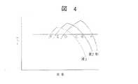
図4に、各圧縮機の標準状態の予測した性能曲線(流量に対するヘッドの関係を示す曲線)と、実際に運転した時の圧縮機の性能曲線の一例を示す。予測された標準状態の性能曲線H2から実際に圧縮機を運転した時の性能曲線が大流量側にずれている例H1と、小流量側にずれている例H3とを併せて示している。予測した性能曲線H2では、圧縮機の流量は点Bから点Eの間で変化するのに対して、性能曲線H1では圧縮機の流量は、点Aから点Dまで変化する。そのため、この圧縮機を性能曲線H2を有する圧縮機とみなして流量制御すると、チョークが起こりやすくなる。また、流量を減らして吐出圧を下げようとしても、流量が低下せず圧縮機の性能を十分に発揮できないという不具合を生じる。
【0038】
同様に、実際の性能曲線がH3となっているときは、圧縮機の流量範囲が点Cから点Fの間にシフトしている。したがって、流量を増やす制御時にはチョーク現象は生じにくくなるものの、流量を減らす制御時は予想よりも早くサージに突入し、不安定な現象を生じるという不具合を生じる。
【0039】
図5に、圧縮機の吸込み条件の変化による、圧縮機の作動範囲が変化する様子を示す。吸込み温度が高いと圧縮機の運転範囲が狭くなり(図5の実線)、吸込み温度が低いと運転範囲が広くなる(図5の破線)。吸込み温度が低い時の運転条件のまま圧縮機を動かし続けると、圧縮機の吸込み温度が上昇した時にはサージやチョークを生ずる恐れがある。また、吸込み温度が高い時の運転条件で圧縮機を動かし続けると、圧縮機の吸込み温度が低下した時には、圧縮機の性能を十分に発揮できないまま圧縮機を運転することなり、消費動力が大きくなる恐れがある。そこで、圧縮機の吐出圧力の変動を測定して各々の圧縮機の運転状態を知れば、複数台の圧縮機を省エネルギー運転できる。なお、図5でG1はインレットガイドベーンを最も開いた状態であり、G2はインレットガイドベーン開度が中間の場合、G3はインレットガイドベーン開度が最も少ない場合である。また、S1はサージ限界である。
【0040】
本実施例によれば、たとえ同じ容量型式の圧縮機を複数揃えて並列接続した場合であっても、個々の圧縮機の製品のばらつきによりサージ限界が異なっていることに着目して、各圧縮機を同時に制御するようにしたので、簡単な制御方法で圧縮機システムを安定に運転できる。また、消費動力を抑えることもできる。なお、上記実施例では、各圧縮機の容量が同一の場合について説明したが、各圧縮機の容量が異なっていても同様に本発明を適用できる。さらに、圧縮機の台数は4台に限らないことは言うまでも無い。
【0041】
【発明の効果】
以上述べたように本発明において、負荷が減少したときに各圧縮機の負荷を低減させ、もっとも早くサージに突入した圧縮機をアンロード運転させるようにすれば、複数の圧縮機を並列に接続した圧縮機システムを簡単な制御で容易に部分負荷運転できる。また、吸込み条件や圧縮機個々の状態が変化しても、効果的に運転できる。
【図面の簡単な説明】
【図1】本発明にかかる圧縮機システム一実施例の模式図である。
【図2】圧縮機システムの部分負荷制御を説明する図である。
【図3】圧縮機システムが消費する消費動力を説明する図である。
【図4】圧縮機システムが備える圧縮機の性能を説明する図である。
【図5】外部条件の変化による圧縮機システムの性能の違いを説明する図である。
【符号の説明】
A0…圧縮機装置、A1…差圧計、10…制御装置、20…吸込み部圧力計、30…吸込み部温度計、40…駆動機、50…インレットガイドベーン、60…圧縮機、70…差圧計、71…オリフィス、72、73…逆止弁、74…吐出部配管、75…配管、80…放風弁、85…レシーバータンク、90…吐出部圧力計。[0001]
BACKGROUND OF THE INVENTION
The present invention relates to a control method and a compressor system for a plurality of compressors in which a plurality of compressors are connected in parallel.
[0002]
[Prior art]
An example of a compressor system in which a plurality of compressors are connected in parallel is described in Japanese Patent Laid-Open No. 2000-120583. In this publication, the load demand flow rate is divided into a plurality of flow rate adjustment ranges so that the sum of the maximum values of the operation compressor supply flow rate is equal to or greater than the load demand flow rate and the number of operation compressors is minimized. At the same time, a flow rate control pattern indicating a combination of operating compressors and a control state of the operating compressor is set for each flow rate adjustment range, and each compressor is controlled according to this setting pattern. When a compressor capable of only on / off control is included, a compressor capable of both constant wind pressure control and on / off control is set as the flow regulator. For a range adjacent to the flow rate setting range set for this compressor, a compressor that can only perform on / off control is preferentially used as a flow rate regulator. As a result, waste during no-load operation can be reduced, and at the same time, it is possible to avoid a plurality of compressors from entering a surge standby state as much as possible.
[0003]
[Problems to be solved by the invention]
In the control method of a plurality of compressors described in the above publication, flow characteristics are determined for each of the plurality of compressors, and each compressor is controlled using a flow control pattern set in advance based on the characteristics. Yes. However, the actual operating point of each compressor is expected due to the internal conditions of the compressor such as the inside of the compressor device becoming dirty and the external conditions such as the temperature and pressure of the fluid entering the compressor changing from season to season. May be different. In that case, if you try to control the compressor using a preset control pattern, the operating point may reach the surge limit earlier than expected, or the compressor may be unloaded before the surge limit. Arise. As a result, there is a possibility that each compressor consumes useless power or that the operation of the compressor becomes unstable due to an unexpected surge.
[0004]
The present invention has been made in view of the above problems of the prior art, and an object of the present invention is to facilitate partial load control with a simple control system in a compressor system having a plurality of compressors. . Another object of the present invention is to reduce power consumption in a compressor system having a plurality of compressors. Still another object of the present invention is to effectively operate a plurality of compressors even in a situation where operating conditions vary. The present invention aims to achieve at least any of these objects.
[0005]
[Means for Solving the Problems]
A feature of the present invention for achieving the above object is amethod for controlling a plurality of turbo compressors connected in parallel, wherein a surge limit of at least one compressor is previously determined and stored in a storage means, When the load on one compressor decreases, the flow rate of all compressors that are in load operation is reduced, the compressor that enters the surge first is unloaded, and the compressor other than the compressor that has been unloaded is When the flow rate is increased to enable operation according to the load, and the load is decreased to reduce the generated flow rate of the compressor, the flow rate is increased by a predetermined amount from the surge limit stored in the storage means. Decrease the flow rate quickly, and then change the flow rate more slowly until the surge rush to generate a surge.When all compressors stop and restart, enter the surge and unload There tobe activated in order from those were.
[0006]
Another feature of the present invention for achieving the above object is a method for controlling a plurality of turbo compressors connected in parallel, wherein a surge limit of at least one compressor is obtained in advance and stored in a storage means. When the load on multiple compressors is reduced, the flow rate of all compressors that are in load operation is reduced, and the compressor that has entered the surge first is unloaded and the compressor other than the compressor that has been unloaded is compressed. When the load is decreased and the generated flow rate of the compressor is reduced by increasing the flow rate of the machine and reducing the generated flow rate of the compressor, the point of the flow rate that is larger than the surge limit stored in the storage means by a predetermined amount The flow rate is reduced quickly until the surge starts, and then the flow rate is changed more slowly until the surge enters, and the load increases when there are multiple unloading compressors. When you return the compressor of the rolling in load operation is to be loaded operation in the order is too early to rush to surge.
[0007]
Further,the present invention that achieves the above object is a compressor system having a plurality of turbo compressors connected in parallel, wherein each of the plurality of compressors discharges an inlet guide vane on the suction side. Each having a surge detection means on the side, and provided with a detection means for detecting the discharge pressure of the compressor system downstream of the connection position on the discharge side of the plurality of compressors connected in parallel. If there are three or more compressors in load operation when the number decreases, the flow rate of all the compressors is reduced, the compressor that entered the surge first is unloaded, and the flow rates of the other compressors are reduced. Control means for controlling each compressor so as to increase, and this control means is provided in each inlet guide vane so that the discharge pressure detected by the discharge pressure detection means becomes a predetermined pressure. There to give the rotation angle command.
[0011]
DETAILED DESCRIPTION OF THE INVENTION
Hereinafter, an embodiment of a method for controlling a plurality of compressors according to the present invention will be described with reference to the drawings. FIG. 1 is a schematic diagram of a compressor system in which a plurality of compressors are connected in parallel, and FIG. 2 is a power consumption diagram when four compressors are connected in parallel. FIG. 3 is a diagram showing the difference between the predicted value and the actual measurement value of the compressor performance diagram, and FIG. 4 is a diagram showing the difference in compressor performance depending on the suction conditions of the gas sucked into the compressor. is there.
[0012]
In the compressor system of the present embodiment, four compressors A0, B0, C0, D0 are connected in parallel as shown in FIG. The compressor control device 10 controls the compressors A0, B0, C0, and D0 connected in parallel. Each of the compressors A0, B0, C0, D0 is a small-capacity turbo compressor having the same model and the same capacity. Since each compressor has the same configuration, the following description will be given taking the compressor A0 as an example. The compressor A0 has a compressor body 60a. An inlet guide vane (IGV) 50a is provided on the suction side of the compressor body 60a to adjust the amount of working gas sucked into the compressor body 60a. A pressure sensor 20a for detecting the suction pressure Ps1 and a temperature sensor 30a for detecting the suction temperature Ts1 are attached further upstream of the inlet guide vane 50a. Note that an opening degree command signal from the control device 10, which will be described in detail later, is input to the inlet guide vane 50a via the signal cable 51a.
[0013]
In order to rotationally drive the compressor main body 60a, the
[0014]
The discharge pressure signal of the compressor main body 60a detected by the differential pressure gauge A1 is input to the control device 10 via the signal line 52a. A branch portion 76a is formed downstream of the differential pressure gauge A1, and a discharge valve 80a is attached to the branched pipe 77a. An instruction signal for discharging compressed gas to the atmosphere or other gas storage means (not shown) is sent from the control device 10 to the air discharge valve 80a via the signal line 53a. On the other hand, a
[0015]
The above is the configuration of the compressor A0. Since the configurations of the compressors B0, C0, and D0 are the same, details are omitted. Next, the control device 10 will be described. The control device 10 has storage means 11 for storing surge limit data of the compressor main bodies 60a to 60d. The controller 10 receives the discharge pressure information of the compressor bodies 60a, 60b,... Detected by the differential pressure gauges A1, B1,... And the signal of the discharge pressure Pd of the compressor system. Although not shown, information of temperature sensors 30a, 30b, ... and pressure sensors 20a, 20b, ... provided on the suction side of the compressor bodies 60a, 60b, ... is also input. On the other hand, the control device 10 issues a command for rotating the inlet guide vanes 50a, 50b,... And a command for opening / closing the air discharge valves 80a, 80b,.
[0016]
The operation of the differential pressure gauge A1 of the present embodiment configured as described above will be described in detail. The pressure of the compressed working gas led from the
[0017]
On the other hand, when the pressure in the
[0018]
Next, an operation control method of the compressor system having a plurality of compressors shown in FIG. 1 will be described with reference to FIG. In FIG. 2, the uppermost stage is the time change of the flow rate discharged from the compressor system, and the lower four stages are the time change of the flow rate discharged from the compressors A0 to D0. An example will be described in which the load is reduced from the state in which all four compressors are loaded. The starting point is the state where the compressor system is operating at 100% load, in other words, 100% flow rate. Note that the discharge pressure detected by the pressure sensor 90 is a pressure at which the pressure when reaching the demand source is higher than the necessary pressure.
[0019]
When the usage amount of the compressed gas from the demand source decreases and the control device 10 detects a decrease in load, the control device instructs each of the compressors A0 to D0 to reduce the flow rate. Specifically, the compressor main bodies 60a, 60b,... Are instructed to rotate the inlet guide vanes 50a, 50b,. As a result, the flow rates of the compressors A0 to D0 are all reduced.
[0020]
Each of the inlet guide vanes is rotated at a high speed until the vicinity of the surge limit point of each compressor main body 60a, 60b,... Stored in the storage means 11 included in the control device 10. This is called α mode. When approaching the surge limit point, the rotational speed of the inlet guide vanes 50a, 50b,... Is reduced to about 1/5 of the rotational speed up to that point. This is called β mode.
[0021]
It is assumed that the
[0022]
Since the compressor A0 is unloaded, the flow rate of the compressor system is drastically reduced. Therefore, the flow rates of the remaining three compressors B0 to C0 are adjusted by rotating so as to open the
[0023]
In this embodiment, the four compressor bodies 60a, 60b,... Have the same capacity and the same model number. However, even though they are the same, each compressor has a different surge entry point, unlike mass-produced products. The reason for this is that the blade angle of the compressor impeller is uneven, it is difficult to accurately align the initial setting angle of the inlet guide vane, or the thickness of the compressor is reduced due to changes in the performance of each compressor. This is because of As a result, the surge entry point is different for each compressor. Moreover, since the differential pressure gauge used in this embodiment has a response speed that can sufficiently detect the difference in surge entry point of each individual compressor, a large number of compressors can be used in a surge region that has been a concern. The problem of driving is not caused.
[0024]
When the flow rate is restored to the flow rate before the compressor A0 enters the surge or a predetermined flow rate smaller than that, the inlet guide vanes 50b of the compressors B0 to D0 are rapidly rotated again in the α mode. As with the operation of four compressors, the inlet guide vanes 50b,... Continue to rotate in the α mode until the surge limit data stored in advance in the storage means 11 and approach the limit data. And the inlet guide vanes 50b,.
[0025]
When the differential pressure gauge B1 of the compressor B0 detects that the compressor B0 has entered a surge, the control device 10 does. The compressor B0 is instructed to fully close the inlet guide vane 50b and open the air discharge valve 80b. Thereby, the compressor B0 is in the γ mode unload operation. At this time, the angle data of the inlet guide vane 50b, which is the surge limit data of the compressor B0 stored in the storage means 11, is replaced with the angle data of the inlet guide vane 50b when entering the surge.
[0026]
Since the compressor B0 is also unloading, the discharge flow rate of the compressor system is drastically decreased again. Therefore, the flow rates of the remaining two compressors C0 and D0 are increased. That is, the discharge flow rate is increased by rapidly rotating the inlet guide vane in the α mode to a flow rate immediately before the compressor B0 enters the surge or a predetermined flow rate equal to or lower than the flow rate. When the required flow rate is much smaller than the flow rate before entering the surge, as shown by the dotted line in the upper part of FIG. 2, it is reasonable and not wasteful to restore the original flow rate. When the discharge flow rate is restored to the predetermined amount or the original flow rate, the inlet guide vane is rotated in the α mode, and when it approaches the surge limit, the mode is shifted to the β mode.
[0027]
When the compressor C0 is operated in the β mode and the differential pressure gauge of the compressor C0 detects a surge inrush, the control device 10 avoids the compressor C0 from the surge. That is, the inlet guide vane angle of the compressor C0 is slightly opened quickly. This is called an α ′ mode. When the compressor is unloaded from this state, if the required flow rate is within a certain range, the required flow rate cannot be achieved by the compressor D01 alone in the unload operation and the flow rate control operation by the rotation of the inlet guide vane. Therefore, the operation of the two compressors is continued. And in order to satisfy the request | requirement flow volume of a compressor system, the compressor C0 carries out a ventilation operation. That is, the discharge valve of the compressor C0 is intermittently opened based on the discharge pressure detected by the pressure sensor 90, and the excess flow rate is discharged. This is called a δ mode. The compressor D0 maintains the inlet guide vane angle when the compressor C0 enters the surge. This is called the ε mode. Note that replacing the surge limit data of the compressor C0 stored in the storage means 11 with the inlet guide vane angle when entering the surge is the same as in the case of the compressors A0 and B0.
[0028]
When the time ratio of the air discharge from the air discharge valve included in the compressor C0 becomes longer, the compressor C0 is set to the unload operation (γ mode), and the compressor D0 is set to the δ mode. That is, the air discharge valve of the compressor D0 is intermittently opened based on the discharge pressure detected by the pressure sensor 90. When the compressor C0 or the compressor D0 performs a ventilating operation, the flow rate sent from each compressor to the receiver tank 85 becomes a value as indicated by the two dotted lines at the bottom in FIG. Therefore, the flow rate generated in the compressor system decreases with time as in the uppermost stage of the figure.
[0029]
Changes in power consumption when the compressors A0 to D0 are controlled as described above are indicated by a one-dot chain line (PT , PA0 to PD0 ) in FIG. The power P of the turbo compressor is expressed as P = γQH / η, where Q is the flow rate, H is the head, γ is the specific weight of the gas, and η is the efficiency. If the efficiency is highest when the flow rate is 100%, and the efficiency is lowest when the flow rate is the minimum, the power consumption curve is approximately as shown in FIG. Further, the compressors A0 to C0 are unloaded, but the consumed power does not become zero at the time of unloading and consumes a predetermined amount of power. Furthermore, although the compressors C0 and D0 perform the air discharge operation, the same power is consumed in the air discharge operation as when the air is not discharged.
[0030]
Next, the case where the gas consumption at the demand source is larger than the gas capacity currently generated by the compressor system will be described. In this case, the discharge pressure detected by the pressure sensor 90 is lower than the predetermined pressure. Therefore, when all the compressors are stopped, the compressor control device 10 selects the compressor with the shortest operating time among the four compressors A0 to D0. If the compressor with the shortest operating time is the compressor C0, the inlet guide vane of the compressor is opened, the vent valve is closed, and the compressor C0 is returned to the load operation.
[0031]
In this state, when the required discharge pressure is not reached, the compressor control device 10 further selects the compressor B0 having the shortest operation time from the remaining three compressors A0, B0, D0. Then, the inlet guide vane 50b is opened, the air discharge valve 80b is closed, and the compressor B0 is returned to the load operation. The same operation is repeated. In this embodiment, the compressor to be returned to the load operation is set according to the operation time. However, the compressor that has entered the surge first may be returned to the load operation. The maximum flow point of each compressor is released from the inlet guide vane so that the compressor controller 10 avoids the surging point and choke point of each compressor based on the signals from the differential pressure gauges A1, B1,. Control the wind valve.
[0032]
According to the present embodiment, the following advantages can be obtained as compared with the case where each compressor is individually controlled. When the inlet guide vanes of the three compressors are closed at the same time, the three inlet guide vanes rotate together until the first surge is entered. On the other hand, it is assumed that each compressor is individually controlled, one compressor is unloaded until the desired discharge pressure is reached, and the remaining two are loaded. FIG. 3 shows a comparison between this state and the power consumption when three units are controlled simultaneously.
[0033]
In FIG. 3, the power consumption for one compressor is P100. The power consumed when one compressor is unloaded is about 10 to 20% (15% in FIG. 3) when one compressor is operated 100%. When one unit is unloaded, its power consumption becomes P15 at 15% of P100. If three units are simultaneously rotated to close the inlet guide vanes and the flow rate of the compressor is controlled, about 7% of power consumption is lost.
[0034]
If it is assumed in FIG. 3 that there is no loss and the flow rate of the compressor is controlled, the power consumption changes from point Z to point A by either method. When the flow rate of the compressor is 60%, the power consumption is P180. Taking into account the operating loss assumed above, the power consumption when controlling the flow rate of the compressor by controlling the inlet guide vanes of three units at the same time is P193, which is a loss of 7% to P180.
[0035]
The power consumption when individually controlling the operation of the compressor is P195 obtained by adding the power consumption P15 in the unload operation of one compressor to the power consumption P180 of the two compressors. That is, the power consumption is reduced by about 1.0% when the inlet guide vanes of the three compressors are simultaneously controlled than when the individual compressors are individually controlled.
[0036]
By the way, if the compressor is operated for a long period of time, dirt may adhere to the flow path surface or the blades of the impeller may be thinned, so that only the performance different from the initially assumed performance may be obtained. In addition, when the gas sucked into the compressor is the atmosphere, the suction conditions vary greatly depending on the season. That is, in the compressor, the two conditions of the external condition and the internal condition are changed and are not necessarily in the standard operating state. This is shown in FIGS.
[0037]
FIG. 4 shows an example of a predicted performance curve (curve indicating the relationship of the head to the flow rate) in the standard state of each compressor and an example of the performance curve of the compressor when actually operated. An example H1 in which the performance curve when the compressor is actually operated is shifted from the predicted standard state performance curve H2 to the large flow rate side and an example H3 in which the performance curve is deviated to the small flow rate side are shown together. In the predicted performance curve H2, the compressor flow rate changes from point B to point E, whereas in the performance curve H1, the compressor flow rate changes from point A to point D. Therefore, if this compressor is regarded as a compressor having a performance curve H2 and the flow rate is controlled, chokes are likely to occur. In addition, even if it is attempted to reduce the discharge pressure by reducing the flow rate, there is a problem that the flow rate does not decrease and the performance of the compressor cannot be fully exhibited.
[0038]
Similarly, when the actual performance curve is H3, the flow rate range of the compressor is shifted between point C and point F. Therefore, the choke phenomenon is less likely to occur during the control for increasing the flow rate, but the control enters the surge earlier than expected during the control for reducing the flow rate, resulting in an unstable phenomenon.
[0039]
FIG. 5 shows how the operating range of the compressor changes due to changes in the suction conditions of the compressor. When the suction temperature is high, the operation range of the compressor is narrowed (solid line in FIG. 5), and when the suction temperature is low, the operation range is widened (broken line in FIG. 5). If the compressor is kept running under the operating conditions when the suction temperature is low, surge or choke may occur when the suction temperature of the compressor rises. Also, if the compressor is kept running under the operating conditions when the suction temperature is high, when the compressor suction temperature is lowered, the compressor will be operated without fully exhibiting the performance of the compressor, resulting in a large power consumption. There is a fear. Then, if the fluctuation | variation of the discharge pressure of a compressor is measured and the operating state of each compressor is known, a plurality of compressors can be operated in an energy saving manner. In FIG. 5, G1 is the state where the inlet guide vane is most opened, G2 is when the inlet guide vane opening is in the middle, and G3 is when the inlet guide vane opening is the smallest. S1 is a surge limit.
[0040]
According to this embodiment, even if a plurality of compressors of the same capacity type are aligned and connected in parallel, paying attention to the fact that the surge limit varies depending on the product variation of each compressor, each compression Since the machine is controlled simultaneously, the compressor system can be stably operated with a simple control method. In addition, power consumption can be reduced. In addition, although the said Example demonstrated the case where the capacity | capacitance of each compressor was the same, even if the capacity | capacitance of each compressor differs, this invention is applicable similarly. Furthermore, it goes without saying that the number of compressors is not limited to four.
[0041]
【The invention's effect】
As described above, in the present invention, when the load is reduced, the load of each compressor is reduced, and the compressor that has entered the surge first is unloaded, so that a plurality of compressors are connected in parallel. The partial compressor operation can be easily performed with simple control. Moreover, even if the suction conditions and the state of each compressor change, it can be operated effectively.
[Brief description of the drawings]
FIG. 1 is a schematic diagram of an embodiment of a compressor system according to the present invention.
FIG. 2 is a diagram illustrating partial load control of a compressor system.
FIG. 3 is a diagram illustrating power consumption consumed by a compressor system.
FIG. 4 is a diagram illustrating the performance of a compressor included in the compressor system.
FIG. 5 is a diagram illustrating a difference in performance of a compressor system due to a change in external conditions.
[Explanation of symbols]
A0 ... Compressor device, A1 ... Differential pressure gauge, 10 ... Control device, 20 ... Suction part pressure gauge, 30 ... Suction part thermometer, 40 ... Driver, 50 ... Inlet guide vane, 60 ... Compressor, 70 ... Differential pressure gauge , 71 ... Orifice, 72, 73 ... Check valve, 74 ... Discharge pipe, 75 ... Pipe, 80 ... Air vent valve, 85 ... Receiver tank, 90 ... Discharge pressure gauge.
Claims (3)
Translated fromJapanesePriority Applications (4)
| Application Number | Priority Date | Filing Date | Title |
|---|---|---|---|
| JP2001282573AJP3741014B2 (en) | 2001-09-18 | 2001-09-18 | Control method and compressor system for a plurality of compressors |
| KR10-2002-0014663AKR100481016B1 (en) | 2001-09-18 | 2002-03-19 | Control method of plural compressors and compressor system |
| CNB021074852ACN1247901C (en) | 2001-09-18 | 2002-03-20 | Multi-compressor control method and compressor system |
| US10/101,312US6773224B2 (en) | 2001-09-18 | 2002-03-20 | Control method of plural compressors and compressor system |
Applications Claiming Priority (1)
| Application Number | Priority Date | Filing Date | Title |
|---|---|---|---|
| JP2001282573AJP3741014B2 (en) | 2001-09-18 | 2001-09-18 | Control method and compressor system for a plurality of compressors |
Publications (2)
| Publication Number | Publication Date |
|---|---|
| JP2003090297A JP2003090297A (en) | 2003-03-28 |
| JP3741014B2true JP3741014B2 (en) | 2006-02-01 |
Family
ID=19106206
Family Applications (1)
| Application Number | Title | Priority Date | Filing Date |
|---|---|---|---|
| JP2001282573AExpired - Fee RelatedJP3741014B2 (en) | 2001-09-18 | 2001-09-18 | Control method and compressor system for a plurality of compressors |
Country Status (4)
| Country | Link |
|---|---|
| US (1) | US6773224B2 (en) |
| JP (1) | JP3741014B2 (en) |
| KR (1) | KR100481016B1 (en) |
| CN (1) | CN1247901C (en) |
Families Citing this family (66)
| Publication number | Priority date | Publication date | Assignee | Title |
|---|---|---|---|---|
| US20070151988A1 (en)* | 2005-12-14 | 2007-07-05 | Saucedo Victor M | Constant pressure delivery vessel and system |
| US7874161B2 (en)* | 2007-07-25 | 2011-01-25 | Honeywell International Inc. | Compressor inlet guide vane flow based anti-ice formation control system and method |
| GB2452287B (en)* | 2007-08-29 | 2012-03-07 | Gardner Denver Gmbh | Improvements in compressors control |
| US8532830B2 (en)* | 2008-07-29 | 2013-09-10 | Shell Oil Company | Method and apparatus for controlling a compressor and method of cooling a hydrocarbon stream |
| US9517679B2 (en) | 2009-03-02 | 2016-12-13 | Flir Systems, Inc. | Systems and methods for monitoring vehicle occupants |
| US9998697B2 (en) | 2009-03-02 | 2018-06-12 | Flir Systems, Inc. | Systems and methods for monitoring vehicle occupants |
| US9235876B2 (en) | 2009-03-02 | 2016-01-12 | Flir Systems, Inc. | Row and column noise reduction in thermal images |
| US9451183B2 (en) | 2009-03-02 | 2016-09-20 | Flir Systems, Inc. | Time spaced infrared image enhancement |
| US9756264B2 (en) | 2009-03-02 | 2017-09-05 | Flir Systems, Inc. | Anomalous pixel detection |
| US9674458B2 (en) | 2009-06-03 | 2017-06-06 | Flir Systems, Inc. | Smart surveillance camera systems and methods |
| US9473681B2 (en) | 2011-06-10 | 2016-10-18 | Flir Systems, Inc. | Infrared camera system housing with metalized surface |
| US10244190B2 (en) | 2009-03-02 | 2019-03-26 | Flir Systems, Inc. | Compact multi-spectrum imaging with fusion |
| US9843742B2 (en) | 2009-03-02 | 2017-12-12 | Flir Systems, Inc. | Thermal image frame capture using de-aligned sensor array |
| USD765081S1 (en) | 2012-05-25 | 2016-08-30 | Flir Systems, Inc. | Mobile communications device attachment with camera |
| US9635285B2 (en) | 2009-03-02 | 2017-04-25 | Flir Systems, Inc. | Infrared imaging enhancement with fusion |
| US9208542B2 (en) | 2009-03-02 | 2015-12-08 | Flir Systems, Inc. | Pixel-wise noise reduction in thermal images |
| US10757308B2 (en) | 2009-03-02 | 2020-08-25 | Flir Systems, Inc. | Techniques for device attachment with dual band imaging sensor |
| US9986175B2 (en) | 2009-03-02 | 2018-05-29 | Flir Systems, Inc. | Device attachment with infrared imaging sensor |
| US9948872B2 (en) | 2009-03-02 | 2018-04-17 | Flir Systems, Inc. | Monitor and control systems and methods for occupant safety and energy efficiency of structures |
| CN101509499B (en)* | 2009-03-19 | 2011-07-27 | 广东省电力工业局试验研究所 | Method and system for preventing fan from surging |
| US9843743B2 (en) | 2009-06-03 | 2017-12-12 | Flir Systems, Inc. | Infant monitoring systems and methods using thermal imaging |
| US9292909B2 (en) | 2009-06-03 | 2016-03-22 | Flir Systems, Inc. | Selective image correction for infrared imaging devices |
| US9819880B2 (en) | 2009-06-03 | 2017-11-14 | Flir Systems, Inc. | Systems and methods of suppressing sky regions in images |
| US9756262B2 (en) | 2009-06-03 | 2017-09-05 | Flir Systems, Inc. | Systems and methods for monitoring power systems |
| US10091439B2 (en) | 2009-06-03 | 2018-10-02 | Flir Systems, Inc. | Imager with array of multiple infrared imaging modules |
| US9716843B2 (en) | 2009-06-03 | 2017-07-25 | Flir Systems, Inc. | Measurement device for electrical installations and related methods |
| US9848134B2 (en) | 2010-04-23 | 2017-12-19 | Flir Systems, Inc. | Infrared imager with integrated metal layers |
| US9207708B2 (en) | 2010-04-23 | 2015-12-08 | Flir Systems, Inc. | Abnormal clock rate detection in imaging sensor arrays |
| US9706138B2 (en) | 2010-04-23 | 2017-07-11 | Flir Systems, Inc. | Hybrid infrared sensor array having heterogeneous infrared sensors |
| US9918023B2 (en) | 2010-04-23 | 2018-03-13 | Flir Systems, Inc. | Segmented focal plane array architecture |
| US10051210B2 (en) | 2011-06-10 | 2018-08-14 | Flir Systems, Inc. | Infrared detector array with selectable pixel binning systems and methods |
| CA2838992C (en) | 2011-06-10 | 2018-05-01 | Flir Systems, Inc. | Non-uniformity correction techniques for infrared imaging devices |
| US9961277B2 (en) | 2011-06-10 | 2018-05-01 | Flir Systems, Inc. | Infrared focal plane array heat spreaders |
| US9235023B2 (en) | 2011-06-10 | 2016-01-12 | Flir Systems, Inc. | Variable lens sleeve spacer |
| CN103828343B (en) | 2011-06-10 | 2017-07-11 | 菲力尔系统公司 | Based on capable image procossing and flexible storage system |
| US9058653B1 (en) | 2011-06-10 | 2015-06-16 | Flir Systems, Inc. | Alignment of visible light sources based on thermal images |
| US10169666B2 (en) | 2011-06-10 | 2019-01-01 | Flir Systems, Inc. | Image-assisted remote control vehicle systems and methods |
| US9706137B2 (en) | 2011-06-10 | 2017-07-11 | Flir Systems, Inc. | Electrical cabinet infrared monitor |
| US10389953B2 (en) | 2011-06-10 | 2019-08-20 | Flir Systems, Inc. | Infrared imaging device having a shutter |
| US10841508B2 (en) | 2011-06-10 | 2020-11-17 | Flir Systems, Inc. | Electrical cabinet infrared monitor systems and methods |
| US9900526B2 (en) | 2011-06-10 | 2018-02-20 | Flir Systems, Inc. | Techniques to compensate for calibration drifts in infrared imaging devices |
| US10079982B2 (en) | 2011-06-10 | 2018-09-18 | Flir Systems, Inc. | Determination of an absolute radiometric value using blocked infrared sensors |
| EP2719167B1 (en) | 2011-06-10 | 2018-08-08 | Flir Systems, Inc. | Low power and small form factor infrared imaging |
| US9143703B2 (en) | 2011-06-10 | 2015-09-22 | Flir Systems, Inc. | Infrared camera calibration techniques |
| US9509924B2 (en) | 2011-06-10 | 2016-11-29 | Flir Systems, Inc. | Wearable apparatus with integrated infrared imaging module |
| DE102011055552A1 (en) | 2011-11-21 | 2013-05-23 | Krones Ag | Internal gripping holding element for container sterilization by means of electron beams |
| EP2604960A1 (en)* | 2011-12-15 | 2013-06-19 | Shell Internationale Research Maatschappij B.V. | Method of operating a compressor and system and method for producing a liquefied hydrocarbon stream |
| ITCO20120008A1 (en) | 2012-03-01 | 2013-09-02 | Nuovo Pignone Srl | METHOD AND SYSTEM FOR MONITORING THE CONDITION OF A GROUP OF PLANTS |
| US9811884B2 (en) | 2012-07-16 | 2017-11-07 | Flir Systems, Inc. | Methods and systems for suppressing atmospheric turbulence in images |
| EP2873058B1 (en) | 2012-07-16 | 2016-12-21 | Flir Systems, Inc. | Methods and systems for suppressing noise in images |
| CN102878100B (en)* | 2012-09-21 | 2014-12-24 | 西安陕鼓动力股份有限公司 | Control method for preventing surging generated during normal halting of single-shaft purified terephthalic acid (PTA) compressor unit |
| CN104214123B (en)* | 2013-06-05 | 2016-12-28 | 中国石油天然气股份有限公司 | Linkage control device and method for double compressors |
| US9973692B2 (en) | 2013-10-03 | 2018-05-15 | Flir Systems, Inc. | Situational awareness by compressed display of panoramic views |
| US9695834B2 (en)* | 2013-11-25 | 2017-07-04 | Woodward, Inc. | Load sharing control for compressors in series |
| US11297264B2 (en) | 2014-01-05 | 2022-04-05 | Teledyne Fur, Llc | Device attachment with dual band imaging sensor |
| KR102247596B1 (en)* | 2014-01-24 | 2021-05-03 | 한화파워시스템 주식회사 | Compressor system and method for controlling thereof |
| KR102198069B1 (en)* | 2016-06-08 | 2021-01-05 | 한국조선해양 주식회사 | Multi gas Compressor Systems |
| ES2899387T3 (en) | 2017-04-06 | 2022-03-11 | Carrier Corp | A method to reduce the maximum input current of a compressor system comprising multiple asynchronous electric motors and a compressor system to implement this method |
| KR101983116B1 (en) | 2017-12-22 | 2019-05-30 | 부림전기 주식회사 | Integrated control system of multi-air compressor and method therof |
| CN110107525B (en)* | 2018-12-10 | 2020-05-05 | 杭州能源投资管理有限公司 | Control method for system pressure of centrifugal air compression station |
| US12258973B2 (en) | 2020-02-10 | 2025-03-25 | Khalifa University of Science and Technology | Apparatus for optimal loadsharing between parallel gas compressors |
| CN113323853B (en)* | 2021-07-08 | 2023-05-05 | 北京康吉森自动化技术股份有限公司 | Unmanned full-automatic control method for air compressor group of air compression station |
| CN113482961B (en)* | 2021-07-26 | 2023-06-02 | 杭州哲达科技股份有限公司 | A smart group control method for centrifugal air compressors based on energy efficiency real-time monitoring |
| CN114656052A (en)* | 2022-04-29 | 2022-06-24 | 重庆江增船舶重工有限公司 | Multistage parallel aeration blower operation method for sewage treatment |
| WO2024054552A2 (en) | 2022-09-07 | 2024-03-14 | Wm Intellectual Property Holdings, L.L.C. | System and method for control of feed compressors in an rng recovery facility for biogas or landfill gas |
| CN116146516B (en)* | 2022-12-05 | 2024-03-12 | 广钢气体(广州)有限公司 | Intelligent grid-connected control method and system for multiple compressors |
Family Cites Families (5)
| Publication number | Priority date | Publication date | Assignee | Title |
|---|---|---|---|---|
| JPS608497A (en)* | 1983-06-29 | 1985-01-17 | Hitachi Ltd | Capacity regulation method and system for multi-stage compressor |
| JPS60147585A (en)* | 1984-01-11 | 1985-08-03 | Hitachi Ltd | Compressor control method |
| US5347467A (en)* | 1992-06-22 | 1994-09-13 | Compressor Controls Corporation | Load sharing method and apparatus for controlling a main gas parameter of a compressor station with multiple dynamic compressors |
| US5343384A (en)* | 1992-10-13 | 1994-08-30 | Ingersoll-Rand Company | Method and apparatus for controlling a system of compressors to achieve load sharing |
| JP2000120583A (en) | 1998-10-14 | 2000-04-25 | Kobe Steel Ltd | Compressor control method and device therefor |
- 2001
- 2001-09-18JPJP2001282573Apatent/JP3741014B2/ennot_activeExpired - Fee Related
- 2002
- 2002-03-19KRKR10-2002-0014663Apatent/KR100481016B1/ennot_activeExpired - Fee Related
- 2002-03-20USUS10/101,312patent/US6773224B2/ennot_activeExpired - Lifetime
- 2002-03-20CNCNB021074852Apatent/CN1247901C/ennot_activeExpired - Fee Related
Also Published As
| Publication number | Publication date |
|---|---|
| JP2003090297A (en) | 2003-03-28 |
| CN1247901C (en) | 2006-03-29 |
| CN1405456A (en) | 2003-03-26 |
| US20030053906A1 (en) | 2003-03-20 |
| KR100481016B1 (en) | 2005-04-07 |
| US6773224B2 (en) | 2004-08-10 |
| KR20030024545A (en) | 2003-03-26 |
Similar Documents
| Publication | Publication Date | Title |
|---|---|---|
| JP3741014B2 (en) | Control method and compressor system for a plurality of compressors | |
| CN102124230B (en) | Improvements in compressor control | |
| CN101842599B (en) | Control System | |
| US7922457B2 (en) | System and method for controlling a variable speed compressor during stopping | |
| JP4248077B2 (en) | Compressor device | |
| US4975024A (en) | Compressor control system to improve turndown and reduce incidents of surging | |
| AU2007347705B2 (en) | Anti-bogdown control system for turbine/compressor systems | |
| JPH0650268A (en) | Device and method of controlling main driving machine for compressor | |
| US11686310B2 (en) | Method for controlling a rotary screw compressor | |
| AU2011242422B2 (en) | Method for controlling a compressor | |
| JP4069675B2 (en) | Turbo compressor and capacity control method thereof | |
| JP5646282B2 (en) | Compressor and operation control method thereof | |
| US4976588A (en) | Compressor control system to improve turndown and reduce incidents of surging | |
| JP3930987B2 (en) | Compressed air production facility and operation method thereof | |
| JP2001082380A (en) | Method and apparatus for controlling the capacity of a gas pumping device | |
| CN110566433A (en) | Air compressor system and control method thereof | |
| JP3590033B2 (en) | Surge prevention method for fluid machinery | |
| JPH06249190A (en) | Controller of number of turbo compressor |
Legal Events
| Date | Code | Title | Description |
|---|---|---|---|
| A621 | Written request for application examination | Free format text:JAPANESE INTERMEDIATE CODE: A621 Effective date:20040121 | |
| A977 | Report on retrieval | Free format text:JAPANESE INTERMEDIATE CODE: A971007 Effective date:20050708 | |
| A131 | Notification of reasons for refusal | Free format text:JAPANESE INTERMEDIATE CODE: A131 Effective date:20050726 | |
| A521 | Written amendment | Free format text:JAPANESE INTERMEDIATE CODE: A523 Effective date:20050913 | |
| TRDD | Decision of grant or rejection written | ||
| A01 | Written decision to grant a patent or to grant a registration (utility model) | Free format text:JAPANESE INTERMEDIATE CODE: A01 Effective date:20051018 | |
| A61 | First payment of annual fees (during grant procedure) | Free format text:JAPANESE INTERMEDIATE CODE: A61 Effective date:20051031 | |
| S111 | Request for change of ownership or part of ownership | Free format text:JAPANESE INTERMEDIATE CODE: R313115 | |
| R371 | Transfer withdrawn | Free format text:JAPANESE INTERMEDIATE CODE: R371 | |
| FPAY | Renewal fee payment (event date is renewal date of database) | Free format text:PAYMENT UNTIL: 20081118 Year of fee payment:3 | |
| S111 | Request for change of ownership or part of ownership | Free format text:JAPANESE INTERMEDIATE CODE: R313115 | |
| FPAY | Renewal fee payment (event date is renewal date of database) | Free format text:PAYMENT UNTIL: 20081118 Year of fee payment:3 | |
| R360 | Written notification for declining of transfer of rights | Free format text:JAPANESE INTERMEDIATE CODE: R360 | |
| FPAY | Renewal fee payment (event date is renewal date of database) | Free format text:PAYMENT UNTIL: 20081118 Year of fee payment:3 | |
| R371 | Transfer withdrawn | Free format text:JAPANESE INTERMEDIATE CODE: R371 | |
| FPAY | Renewal fee payment (event date is renewal date of database) | Free format text:PAYMENT UNTIL: 20081118 Year of fee payment:3 | |
| FPAY | Renewal fee payment (event date is renewal date of database) | Free format text:PAYMENT UNTIL: 20081118 Year of fee payment:3 | |
| S111 | Request for change of ownership or part of ownership | Free format text:JAPANESE INTERMEDIATE CODE: R313111 | |
| FPAY | Renewal fee payment (event date is renewal date of database) | Free format text:PAYMENT UNTIL: 20081118 Year of fee payment:3 | |
| R350 | Written notification of registration of transfer | Free format text:JAPANESE INTERMEDIATE CODE: R350 | |
| FPAY | Renewal fee payment (event date is renewal date of database) | Free format text:PAYMENT UNTIL: 20081118 Year of fee payment:3 | |
| FPAY | Renewal fee payment (event date is renewal date of database) | Free format text:PAYMENT UNTIL: 20091118 Year of fee payment:4 | |
| FPAY | Renewal fee payment (event date is renewal date of database) | Free format text:PAYMENT UNTIL: 20101118 Year of fee payment:5 | |
| FPAY | Renewal fee payment (event date is renewal date of database) | Free format text:PAYMENT UNTIL: 20101118 Year of fee payment:5 | |
| FPAY | Renewal fee payment (event date is renewal date of database) | Free format text:PAYMENT UNTIL: 20111118 Year of fee payment:6 | |
| FPAY | Renewal fee payment (event date is renewal date of database) | Free format text:PAYMENT UNTIL: 20111118 Year of fee payment:6 | |
| FPAY | Renewal fee payment (event date is renewal date of database) | Free format text:PAYMENT UNTIL: 20121118 Year of fee payment:7 | |
| FPAY | Renewal fee payment (event date is renewal date of database) | Free format text:PAYMENT UNTIL: 20131118 Year of fee payment:8 | |
| S111 | Request for change of ownership or part of ownership | Free format text:JAPANESE INTERMEDIATE CODE: R313111 | |
| R350 | Written notification of registration of transfer | Free format text:JAPANESE INTERMEDIATE CODE: R350 | |
| S111 | Request for change of ownership or part of ownership | Free format text:JAPANESE INTERMEDIATE CODE: R313111 | |
| R350 | Written notification of registration of transfer | Free format text:JAPANESE INTERMEDIATE CODE: R350 | |
| LAPS | Cancellation because of no payment of annual fees |