JP3740760B2 - Recording device - Google Patents
Recording deviceDownload PDFInfo
- Publication number
- JP3740760B2 JP3740760B2JP29475296AJP29475296AJP3740760B2JP 3740760 B2JP3740760 B2JP 3740760B2JP 29475296 AJP29475296 AJP 29475296AJP 29475296 AJP29475296 AJP 29475296AJP 3740760 B2JP3740760 B2JP 3740760B2
- Authority
- JP
- Japan
- Prior art keywords
- recording
- gear
- recording medium
- carriage
- head
- Prior art date
- Legal status (The legal status is an assumption and is not a legal conclusion. Google has not performed a legal analysis and makes no representation as to the accuracy of the status listed.)
- Expired - Fee Related
Links
Images


Classifications
- B—PERFORMING OPERATIONS; TRANSPORTING
- B41—PRINTING; LINING MACHINES; TYPEWRITERS; STAMPS
- B41J—TYPEWRITERS; SELECTIVE PRINTING MECHANISMS, i.e. MECHANISMS PRINTING OTHERWISE THAN FROM A FORME; CORRECTION OF TYPOGRAPHICAL ERRORS
- B41J15/00—Devices or arrangements of selective printing mechanisms, e.g. ink-jet printers or thermal printers, specially adapted for supporting or handling copy material in continuous form, e.g. webs
- B41J15/04—Supporting, feeding, or guiding devices; Mountings for web rolls or spindles
- B—PERFORMING OPERATIONS; TRANSPORTING
- B41—PRINTING; LINING MACHINES; TYPEWRITERS; STAMPS
- B41J—TYPEWRITERS; SELECTIVE PRINTING MECHANISMS, i.e. MECHANISMS PRINTING OTHERWISE THAN FROM A FORME; CORRECTION OF TYPOGRAPHICAL ERRORS
- B41J11/00—Devices or arrangements of selective printing mechanisms, e.g. ink-jet printers or thermal printers, for supporting or handling copy material in sheet or web form
- B41J11/66—Applications of cutting devices
- B41J11/663—Controlling cutting, cutting resulting in special shapes of the cutting line, e.g. controlling cutting positions, e.g. for cutting in the immediate vicinity of a printed image
- B—PERFORMING OPERATIONS; TRANSPORTING
- B41—PRINTING; LINING MACHINES; TYPEWRITERS; STAMPS
- B41J—TYPEWRITERS; SELECTIVE PRINTING MECHANISMS, i.e. MECHANISMS PRINTING OTHERWISE THAN FROM A FORME; CORRECTION OF TYPOGRAPHICAL ERRORS
- B41J11/00—Devices or arrangements of selective printing mechanisms, e.g. ink-jet printers or thermal printers, for supporting or handling copy material in sheet or web form
- B41J11/66—Applications of cutting devices
- B41J11/666—Cutting partly, e.g. cutting only the uppermost layer of a multiple-layer printing material
- B—PERFORMING OPERATIONS; TRANSPORTING
- B41—PRINTING; LINING MACHINES; TYPEWRITERS; STAMPS
- B41J—TYPEWRITERS; SELECTIVE PRINTING MECHANISMS, i.e. MECHANISMS PRINTING OTHERWISE THAN FROM A FORME; CORRECTION OF TYPOGRAPHICAL ERRORS
- B41J11/00—Devices or arrangements of selective printing mechanisms, e.g. ink-jet printers or thermal printers, for supporting or handling copy material in sheet or web form
- B41J11/66—Applications of cutting devices
- B41J11/70—Applications of cutting devices cutting perpendicular to the direction of paper feed
- B—PERFORMING OPERATIONS; TRANSPORTING
- B41—PRINTING; LINING MACHINES; TYPEWRITERS; STAMPS
- B41J—TYPEWRITERS; SELECTIVE PRINTING MECHANISMS, i.e. MECHANISMS PRINTING OTHERWISE THAN FROM A FORME; CORRECTION OF TYPOGRAPHICAL ERRORS
- B41J3/00—Typewriters or selective printing or marking mechanisms characterised by the purpose for which they are constructed
- B41J3/407—Typewriters or selective printing or marking mechanisms characterised by the purpose for which they are constructed for marking on special material
- B41J3/4075—Tape printers; Label printers
Landscapes
- Handling Of Sheets (AREA)
- Printers Characterized By Their Purpose (AREA)
- Impression-Transfer Materials And Handling Thereof (AREA)
Description
Translated fromJapanese【0001】
【発明の属する技術分野】
本発明は、被記録媒体に文字等のキャラクタやマークを記録する記録装置であって、特に、長尺状の被記録媒体を切断して使用する記録装置に関する。
【0002】
【従来の技術】
従来、この種の記録装置においては、記録ヘッドに対して搬送される記録用紙を支持するプラテンと、このプラテンの下流側に配設された記録用紙を切断する切断装置とを備えている。そして、記録ヘッドが記録用紙に記録した後、記録用紙を切断装置側へ搬送して、切断装置を作動させ、記録用紙を切断している。
【0003】
【発明が解決しようとする課題】
しかし、切断装置が作動して記録用紙を切断する際に、切断装置のカッター等によって、記録用紙が引っ張られて、記録用紙の搬送機構に用いられているギヤトレイン中にバックラッシュが生じることがある。そのため、記録ヘッドが記録用紙に記録した後に切断装置を作動させ、再度記録用紙に記録を行う場合、切断前に記録した部分と切断後に記録した部分との間に、いわゆるホワイトラインとか、もしくは、著しい記録の重なりとかが生じてしまうことがある。
【0004】
本発明は、上記の問題を解決するために為されたものであり、被記録媒体における切断前に記録した部分と切断後に記録する部分との間に、ホワイトラインとか、もしくは、著しい記録の重なりとかが生じることを防止できる記録装置を提供することを目的とする。
【0005】
【課題を解決するための手段】
前記目的を達成するために、請求項1に係る発明の記録装置によれば、記録素子を少なくとも一方向に列設した記録ヘッドと、この記録ヘッドに対して、長尺状の被記録媒体の先端部を前記列設方向に搬送させる搬送手段と、前記被記録媒体の前記搬送方向における記録ヘッドの下流側に配設され、その被記録媒体を切断する切断装置とを備え、前記記録素子の列設長さとほぼ同じ長さ分単位で被記録媒体の先端部を搬送させ、その搬送の停止状態で、記録ヘッドが記録動作を行う記録装置において、前記切断装置の切断動作の直前における被記録媒体の搬送量を、前記記録素子の列設長さとほぼ同じ長さ分より少なくし、切断装置の切断動作を行った後に、残りの搬送量だけ搬送した状態で、前記記録ヘッドが記録を行う制御手段を有することを特徴とする。
【0006】
それにより、制御手段は、切断装置の切断動作の直前における被記録媒体の搬送量を、前記記録素子の列設長さとほぼ同じ長さ分より少なくし、切断装置の切断動作を行った後に、残りの搬送量だけ搬送した状態で、記録ヘッドが記録を行う制御を行うので、切断装置のカッター等によって被記録媒体が引っ張られて、被記録媒体の搬送機構に用いられているギヤトレイン中にバックラッシュが生じても、残りの搬送量だけ搬送する際に、そのバックラッシュ分だけ調整すればよい。それにより、被記録媒体における切断前に記録した部分と切断後に記録する部分との間に、ホワイトラインとか、もしくは、著しい記録の重なりとかが生じることを防止できる。
【0007】
また、請求項2に係る発明の記録装置によれば、前記被記録媒体の裏面側には、片面に剥離紙を重ね合わせた両面粘着テープが貼付けられている。それにより、剥離紙を両面粘着テープから剥せば、例えば、ファイルの背表紙等の被貼付物に、その両面粘着テープを介して、被記録媒体を貼付けることができる。
【0008】
また、請求項3に係る発明の記録装置によれば、記録素子は、発熱素子であって、その列設方向に交差する方向に、記録ヘッドを往復搬送するヘッド搬送手段を設けた。それにより、記録ヘッドは、幅広の被記録媒体に対して記録素子の列設方向と交差する方向に往復搬送し、発熱素子が選択的に発熱すれば、シリアル記録モードで幅広の被記録媒体に記録することができる。
【0009】
【発明の実施の形態】
以下、本発明の実施の形態について、図面に基づいて説明する。
本実施の形態の記録装置は、図1に示されるように、ひらがなや漢字や記号などの多数のキャラクタまたはマーク等を、幅広または幅狭の被記録媒体(テープ)に印字するテープ印字装置1である。このテープ印字装置1の内部には、第1の被記録媒体としての幅狭の被記録媒体D1を単色にて記録するテープステーションTSと、第2の被記録媒体としての幅広の被記録媒体D2をカラー又は単色のいずれかにて記録するワイドステーションWSとの2ステーションが設けられている。それにより、記録終了後、テープ印字装置1の本体フレーム2の一方向(左方)側の側部の排出口(図示せず)から、テープステーションTSで単色で記録された幅狭の被記録媒体D1が排出されるのに対し、本体フレーム2前面中央の排出口2aから、ワイドステーションWSでカラー又は単色で記録された幅広の被記録媒体D2が排出されるようになっている。
【0010】
また、キーボード3上には、改行キー、ひらがななどのキャラクタを入力する為の複数の文字キーやマークキー等の他に、種々のキー、例えば、実行キーや取消しキーなどの編集キー、縦書きもしくは横書きの設定キーなどが配設されている。そして、前記テープ印字装置1とキーボード3との間にケーブル線4を接続すると、このケーブル線4を介して、キーボード3上の各種キーを介して入力されたデータ等の信号を、送受信することができる。また、前記本体フレーム2の前面右方側には、表示装置としてのディスプレイ5が設けられ、このディスプレイ5は、キーボード3から入力されたキャラクタやマーク等を、複数行に渡ってその画面上に表示することができる。
【0011】
その本体フレーム2の前面側部には、手前側に開閉可能なカバーケース7が設けられ、利用者は、このカバーケース7を開け、前記テープカセットTCまたはワイドステーションWS時に使用されるカラー又は単色のリボンカセットRCのいずれかをキャリッジCA上にセットして、カバーケース7を閉じることができる。それにより、利用者は、単色で記録された幅狭の被記録媒体D1を、または、カラー又は単色で記録された幅広の被記録媒体D2のいずれかを希望するかにより、テープカセットTCまたはリボンカセットRCのいずれか一方を選択して、カバーケース7内のキャリッジCA上にセットできる。尚、本実施の形態のテープ印字装置1では、テープステーションTSにおいて、幅狭の被記録媒体D1に単色でのみ記録できるが、必ずしもこの態様に限定される訳ではなく、フルーカラーの記録ができるように変更しても良い。
【0012】
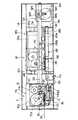
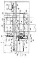
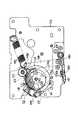
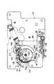
図2及び図3は、本実施の形態のテープ印字装置1内部の記録機構の主要部を示す正面図及び平面図である。前記テープステーションTSとは、図2及び3に示される本体フレーム2内部に、前後に延設された底面側シャーシHSの左側の記録領域をいい、ワイドステーションWSとは、前記底面側シャーシHSの右側の記録領域をいう。そのテープステーションTSでは、ライン記録モードで記録が行われる。このライン記録モードでは、テープカセットTCから引き出される幅狭の被記録媒体D1と、この被記録媒体D1に対して記録を行う際に使用するインクリボンIR等とを一方向、即ち本体フレーム2の側部外方に向かうように搬送させる。そして、固定された状態の記録ヘッドHDが、そのインクリボンIRを介して、幅狭の被記録媒体D1に記録し、その記録された被記録媒体D1のみが本体フレーム2の側部外方に排出される。
【0013】
一方、前記ワイドステーションWSでは、シリアル記録モードで記録が行われる。このシリアル記録モードでは、幅広の被記録媒体D2の搬送方向(即ち、図3の上方から下方の方向)と交差する主走査方向(即ち、図2及び3の左右方向)に記録ヘッドHDを搬送しながら、記録ヘッドHDが被記録媒体D2に対して記録を行い、その記録終了後に被記録媒体D2を前記搬送方向に所定量搬送し、再び主走査方向に搬送しながら記録する。
【0014】
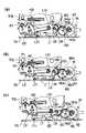
具体的には、キャリッジ搬送機構CHが、キャリッジCAを、幅広の被記録媒体D2の搬送方向と交差する主走査方向に往復搬送させながら、図4(b)に示されるように、記録ヘッドHDは被記録媒体D2の主走査方向に記録を行い(図示のごとく「あ」「い」「う」「え」「お」の行、及び、「か」「き」「く」「け」の行を同時に記録)、その記録終了後に、幅広の被記録媒体D2の搬送機構QHが、図3の上方から下方に向かう搬送方向に被記録媒体D2を所定量(多数の発熱素子の配列分L1(図4(a)参照))、即ち、記録素子の列設長さと同じ長さ分だけ搬送する。そして、キャリッジ搬送機構CHが、再び被記録媒体D2の主走査方向にキャリッジCAを搬送することにより、記録ヘッドHDは被記録媒体D2に記録し(図示のごとく「さ」「す」「し」「せ」「そ」を記録)、更に同様の態様を繰り返す。
尚、前記被記録媒体D2の搬送量は、前記発熱素子の配列分L1よりも発熱素子1個〜数個分少なく設定することも可能である。この場合、被記録媒体D2の搬送方向における1行目の記録結果の後端と2行目の記録結果の前端とが、発熱素子1個(ドット)〜数個(数ドット)分重ねて記録されることになって、1行目の記録結果の後端と2行目の記録結果の前端との間には隙間なくなる。しかし、人間の目の認識能力を考慮すれば、その程度の記録の重なりでは、何等問題が生じないので、被記録媒体D2の搬送量を発熱素子の列設分L1の長さと同じ長さか、あるいは、それよりも発熱素子1個〜数個分少なく設定することが可能となる。従って、被記録媒体D2の搬送量は、発熱素子の列設長さとほぼ同じ長さ分だけ搬送することになる。
【0015】
このキャリッジ搬送機構CHは、本体フレーム2内部の右側端部に設置されたステップモータSMと、このモータSMの駆動軸SM1の上方側に歯合するように取り付けられた小径の駆動ギヤ部SM2と、このギヤ部SM2と歯合する大径の駆動ギヤ部SM3(図3参照)と、このギヤ部SM3と一体的に回動するタイミングベルト用の駆動プーリSP2と、本体フレーム2内部の左側端部に設けられたタイミングベルト用の従動プーリSP1と、これら両プーリSP1、SP2間を掛け渡されるとともに、キャリッジCAの後端部CA1と連結されたタイミングベルトTBと、キャリッジCAの後端支持部CA2を貫通して本体フレーム2内部に架け渡されるキャリッジCA支持用のガイド軸GDとを備えている。
【0016】
それにより、ステップモータSMが正転または逆転駆動すると、前記駆動軸SM1及び駆動ギヤ部SM2、SM3を介して、駆動プーリSP2が一方向または反対方向に回転し、タイミングベルトTBを一方向または反対方向に移動させる。そのため、タイミングベルトTBの移動に伴って、記録ヘッドHDを搭載するキャリッジCAは、前記両プーリSP1、SP2間をガイド軸GDに沿って、図2及び3の左右方向にステップ送りされるので、図2、3の実線で示されるごとく、テープステーションTSに配置されたり、あるいは図2、3の二点鎖線で示されるごとく、ワイドステーションWSの記録領域を往復移動する。尚、前記ステップモータSMの制御パルス量と、タイミングベルトTBの送り量とは、正確に対応しているので、図14に示される制御装置CPが、ステップモータSMにその制御パルスを所定量だけ送れば、タイミングベルトTBが所定量だけ送られて、キャリッジCAは、正確に搬送制御されることになる。
【0017】
前記幅広の被記録媒体D2の搬送機構QHは、本体フレーム2内部の後方側に戴置された巻装状態の被記録媒体D2を支持する支持用突起ST1、ST2と、被記録媒体D2の主走査方向にその順番に所定距離だけ離して並設された用紙送りローラ部JR1、JR2とを備える。具体的には、前記シャーシKS及び長辺側シャーシHS2の間には、支持用突起ST2、ST1がシャーシKS及び長辺側シャーシHS2にそれぞれ取り付けられ、これら支持用突起ST1、ST2は、巻装された被記録媒体D2の中軸空間部D2aに両側から挿入されて、その媒体D2を支持する(図4参照)。尚、図4の二点鎖線で示されるようなカセットケースHS0が、巻装状態の被記録媒体D2を収納するのが望ましいが、必ずしもその態様に限定される必要はない。
【0018】
この場合、底面側シャーシHS側の支持用突起ST1には、圧縮スプリングABが、突起ST1を前記シャーシKSに向かって付勢するように、取り付けられている。一方、シャーシKS側の支持用突起ST2は、被記録媒体D2の用紙幅に対応するように、底面側シャーシHS側の支持用突起ST1側に向かって移動可能となっているので、例えば、図3の実線もしくは二点鎖線で示されるごとく、被記録媒体D2の用紙幅が異なっても、両支持用突起ST1、ST2は、被記録媒体D2を確実に巻装状態に保って、被記録媒体D2の先端側を用紙送りローラ部JR1、JR2方向に送り出すことができる。
【0019】
これらローラ部JR1、JR2は、前記底面側シャーシHS内の長辺側シャーシHS2と、ワイドステーションWS側のシャーシKSとの間にそれぞれ回動可能に架設されている。また、前記底面側シャーシHS内の短辺側シャーシHS1のテープステーションTS側には、ステップモータSNが固着されている。そのため、このモータSNの正転または逆転の駆動力が、前記長辺側シャーシHS2に沿って並設された用紙送り用のギヤトレインGYを構成するギヤY1〜Y7、ST3、ST4等を介して伝達することにより、前記支持用突起ST1、ローラ部JR1、JR2が時計回りまたは反時計回り方向に回動する。
【0020】
前記ローラ部JR1、JR2は、上下一対のローラ軸JR1a、JR2aに複数の用紙送りローラJR1b、JR2bをそれぞれ取り付けてなる。そのため、これらローラJR1b、JR2bが相互に圧着された状態で、それらローラJR1b、JR2b間に、巻装された被記録媒体D2の先端部が挟み込まれて、ローラJR1b、JR2bが回転すると、被記録媒体D2は引き出されるように前方側に向かって搬送されたり、もしくは巻戻されるように後方側に向かって搬送される。
【0021】
また、用紙送りローラ部JR1、JR2間の記録ヘッドHDが通過する底面側には、第2のプラテンP2が設けられており、このプラテンP2は、被記録媒体D2を支持する面が、ほぼ平板状に形成されている。この場合、仮に、第2のプラテンP2に円筒状プラテンを使用すると、記録ヘッドHDの記録を行う発熱素子が円筒状プラテンと直交するため、記録ヘッドHDの発熱素子の上下端部側が、円筒状プラテンと十分に圧接されずに、記録結果に掠れや抜け等が生じやすくなる。それにより、第2のプラテンP2は、ほぼ平板状に形成されていれば、かかる事態を防止できるので、円筒状プラテンよりも平面状プラテンを使用するのが望ましい。
【0022】
このプラテンP2の側方(図3左側)の上面には、センサ用マークSXが設けられており、このマークSXは、記録ヘッドHDが左右方向に往復移動する際に、ワイドステーションWS側における記録ヘッドHDの移動用原点を検出するために使用される。即ち、制御装置CPがステップモータSMに制御パルスを所定量だけ送って、記録ヘッドHDを主走査方向に往動しながら記録させる際、そのマークSXによるワイドステーションWS側の移動用原点は、記録ヘッドHDの位置制御の基準となる。
【0023】
具体的には、そのマークSXは、反射領域と非反射領域を交互に有する2パターンからなっていて、キャリッジCA上に搭載された反射型センサ(図示せず)が、プラテンP2上に貼り付けられたターゲットとしての前記マークSXを検出する。そして、前記反射型センサが、反射状態から非反射状態に変化する変化点を2回検出した位置を、制御装置CPが前記原点と判断する。これは、仮に、変化点が1ヶ所の場合、黒いプラテンに対して白い被記録媒体D2があると、用紙とプラテンの境を、制御装置CPが変化点と判断して誤検出するからである。このような誤検出を防止するためには、上記のような2パターンからなるセンサ用マークSXを設けるのが望ましい。
【0024】
また、ローラ部JR2の下流側の近傍には、被記録媒体D2の先端を検出する検出センサSWが設けられており、このセンサSWの出力信号に基づいて、被記録媒体D2の搬送制御が行われる。例えば、利用者が被記録媒体D2を本体フレーム2内部の後方側の所定位置にセットし、その先端側を用紙送りローラ部JR1、JR2方向に送り出して、用紙送り可能な状態となる。そして、ステップモータSNの正転駆動を、前記ギヤトレインGYを介して伝達し、前記両ローラ部JR1、JR2及び支持用突起ST1を回転させるが、前記制御装置CPは、前記センサSWが被記録媒体D2の先端を検出するまで、ステップモータSNを駆動する。尚、前記ステップモータSNの制御パルス量と、被記録媒体D2の送り量とは、蛇行等の送りエラーが無い限り、正確に対応しているので、制御装置CPが、ステップモータSNにその制御パルスを所定量だけ送れば、被記録媒体D2の搬送制御が行われることになる。
【0025】
また、ローラ部JR2の下流側には、被記録媒体D2をカットする切断装置KCが設けられており、この切断装置KCが、前記被記録媒体D2の搬送制御の下に、所定のタイミングで作動することにより、被記録媒体D2を切断する。その切断装置KCは、例えば、その刃部KC1(図4参照)が、被記録媒体D2の幅方向(図3の左右方向)に往復動して切断するタイプのものであっても良いし、それ以外に、刃部KC1の刃渡りが被記録媒体D2の幅分だけあって、上下動して切断するタイプのものであっても良く、要は被記録媒体D2を切断できればよい。
【0026】
そして、被記録媒体D2における切断前に記録した部分と切断後に記録した部分との間に、ホワイトラインとか、もしくは、著しい記録の重なりとかが生じることを防止するため、制御装置CPは以下の制御を行う。即ち、制御装置CPは、図4(a)に明示されるように、通常、発熱素子の配列分(L1)単位で媒体D2の先端部を搬送させ、その停止状態で記録ヘッドHDが記録動作を行うが、切断装置KCの切断動作の直前における被記録媒体D2の搬送量(L3)を、発熱素子の配列分(L1)より少なくする。そして、切断装置KCの切断動作を行った後に、残りの搬送量L4(=L1−L3)だけ搬送し、記録ヘッドHDが記録を行う。
【0027】
具体的には、制御装置CPは、前記ローラ部JR1、JR2を回動させて、発熱素子の配列分(L1)単位で媒体D2の先端部を搬送させ、その停止状態で、キャリッジ搬送機構CHが駆動することによってキャリッジCAを搬送しながら、記録ヘッドHDが、インクリボンIRを介して、被記録媒体D2の主走査方向に記録動作を行う。その際、制御装置CPは、この実施の形態の場合、被記録媒体D2の切断を行う2行目前の記録か否かを判断し、2行目前の記録でない場合は、通常通り、発熱素子の配列分(L1)単位で媒体D2の先端部を搬送させる。そして、制御装置CPは、被記録媒体D2の切断を行う2行目前の記録であると判断すると、その記録の終了後に、発熱素子の配列分(L1)より少ない搬送量(L3)だけ搬送する。
【0028】
そして、制御装置CPは、切断装置KCの切断動作を行って被記録媒体D2の先端部を切断した後に、残りの搬送量L4(=L1−L3)だけ搬送して、次の記録を行う。それにより、切断装置KC等によって被記録媒体D2が引っ張られて、被記録媒体D2の搬送用ギヤトレインGY等にバックラッシュが生じても、残りの搬送量L4(=L1−L3)だけ搬送する際に、そのバックラッシュ分だけ調整すればよい。そのため、被記録媒体D2における切断前に記録した部分と切断後に記録する部分との間に、ホワイトラインとか、もしくは、著しい記録の重なりとかが生じることがない。
【0029】
もっとも、制御装置CPが被記録媒体D2の切断を行う2行目前の記録であるか否かを判断するのは、切断装置KCと記録ヘッドHDとの位置関係に依存するにすぎないため、それ以外の行の記録終了後に切断装置KCで駆動させてもよい。特に、切断装置KCの駆動によって、被記録媒体D2がギヤのバックラッシュ分以上搬送される機構の場合、そのバックラッシュ分以上の搬送量を予め把握して、切断装置KCの切断動作を行った後残りの搬送量だけ搬送する際に、調整するようにしてもよい。
【0030】
次に、キャリッジCAの構造について説明する。そのキャリッジCAの表面(載置面)側には、幅狭の被記録媒体D1及びインクリボンIR等を収納したテープカセットTC(図2、5、7参照)、もしくは、インクリボンIRのみを収納したインクカセットRC(図8参照)を選択的に戴置することができるのに対し、その裏面側には、ステップモータSL(図3、6参照)を搭載している。そのステップモータSLは、キャリッジCA上にセットされるカセットTC内のインクリボンIR等のテープ送りのために使用される他、ワイドステーションWS時における記録ヘッドHD及び幅広の被記録媒体D2間の圧接及び離間のために使用される。このように二つの用途に駆動源としてのステップモータSLを利用する理由は、ステップモータSLの駆動力を有効に活用するためである。
【0031】
キャリッジCAの下方側には、記録ヘッドHDが取り付けられ、この記録ヘッドHDの記録面側には、1ドット単位で発熱可能な発熱素子が、多数一ライン状に所定距離(印刷幅L1(図4参照))分だけ配設されている。そして、ステップモータSL等の駆動力を使用するテープ送り機構が、キャリッジCA上に戴置された前記カセットTC内の被記録媒体(テープ)D1等を、前記発熱素子の配列方向に交差しながら、記録ヘッドHDの記録面側に搬送するので、発熱素子の発熱がインクリボンIRのインクを溶かして、そのインクを1ドット単位で被記録媒体D1に付着することができる。
【0032】
そのテープカセットTCは、図7に示されるように、テープステーションTS時に使用する幅狭の被記録媒体D1及びインクリボンIRを、ほぼ矩形状のカセットケース内に収納したものである。一方、リボンカセットRCは、図8に示されるように、ワイドステーションWS時に使用する幅狭のインクリボンIRを、ほぼ矩形状のカセットケース内に収納したものであって、テープカセットTCと異なり、幅狭の被記録媒体D1を収納していない。
【0033】
具体的には、テープカセットTCは、図5、7に示されるように、例えば、透明テープ等からなる幅狭の被記録媒体D1、この幅狭の被記録媒体D1に印字を施すためのインクリボンIR、更には、印字がなされた幅狭の被記録媒体D1に裏貼される両面粘着テープYTをそれぞれリールTC1、TC2、TC3に巻回して収納したものであり、更に、使用済みのインクリボンIRを巻取るインクリボン巻取リールTC4を備えている。
【0034】
そして、前記リールTC2に巻回され、このリールTC2から引き出された幅狭の未使用インクリボンIRは、幅狭の被記録媒体D1と重ね合わされ、幅狭の被記録媒体D1と共に開口部TC5に入り、記録ヘッドHD及びプラテンP1間を通過する。その後、インクリボンIRは、幅狭の被記録媒体D1から離され、前記ステップモータSLから駆動を受けるインクリボンIRの巻取リールTC4に至り、このリールTC4により巻取られる。
【0035】
尚、テープカセットTCをキャリッジCA上にセットした状態で、そのリールTC4内には、キャリッジCAの表面側に突設されているリボン巻取用のカム部材PC4aを挿通するが、このリールTC4の内部には、リールTC4と一体的に駆動する駆動カムホロワTC4bが挿着されている。そのため、リールTC4は、駆動カムホロワTC4bとカム部材PC4aとの係合の下に、キャリッジCA上に設けられたギヤトレイン(後述)を介して、ステップモータSLの駆動力を受けて回転し、使用済みのインクリボンIRを巻取ることができる。
【0036】
また、前記両面粘着テープYTは、片面に剥離紙を重ね合わされた状態で、剥離紙を外側にしてリールTC3に巻回されて収納されている。そして、このリールTC3から引き出された両面粘着テープYTは、テープ駆動ローラTC6とテープ貼合せローラP3との間を通過し、剥離紙が重ね合わされない側の粘着面が幅狭の被記録媒体D1に貼着される。尚、前記被記録媒体D2についても、片面に剥離紙を重ね合わせた両面粘着テープが、その媒体D2の裏面側に貼着されているのが望ましい。
【0037】
それにより、前記リールTC1に巻回され、このリールTC1から引き出された幅狭の被記録媒体D1は、終端検出用または色検出用の一対のセンサSE、ガイドピンTB1等を経由して、テープカセットTCの開口部TC5を通過する。その後、両面粘着テープYTが貼合わされる幅狭の被記録媒体D1は、テープカセットTCの片側下方部に回転自在に設けられ、ステップモータSLの駆動を受けて回転するテープ駆動ローラTC6と、このローラTC6に対向配置されるテープ貼合せローラP3との間を通過して、テープカセットTCの外部に至て、前記本体フレーム2から排出される。この場合、両面粘着テープYTは、被記録媒体D1に対して両ローラTC6、P3とによって圧接される。
【0038】
尚、テープ貼合せローラP3は、プラテンP1と並んでローラホルダLDに支持されている。そのため、このローラホルダLDは、テープ駆動ローラTC6とテープ貼合せローラP3とを、更には、記録ヘッドHDと第1のプラテンP1とを相互に圧接及び離間することができる。その場合、第1のプラテンP1は、被記録媒体D1搬送のために回転できる方がよいので、円筒状プラテンを使用するのが望ましい。
【0039】
尚、そのテープ駆動ローラTC6には、図7に示されるように、貫通孔部TC8が設けられており、この貫通孔部TC8には、テープ駆動ローラ用カムホロワTC9が形成されている。そのため、その貫通孔部TC8内に、キャリッジCAの表面側に突設されているテープ駆動用カム部材PC6bを挿通すると(図9参照)、このテープ駆動用カム部材PC6bは、カムホロワTC9と係合できる。一方、前記リールTC3内には、キャリッジCAの表面側に突設されているテープ送り用のカム部材PC3aが挿通されているが、リールTC3の内部には、リールTC3と一体的に回動する駆動カムホロワが装着されておらず、カム部材PC3aは空回転するだけなので、両面粘着テープYTの送りには、なんらの影響を与えない。
【0040】
また、リボンカセットRCは、ワイドステーションWS時に、幅広の被記録媒体D2の記録面D2bに印字を施すため(図4参照)、インクリボンIRの両先端部を、未使用インクリボン巻取り用のリールRC1、使用済みインクリボン巻取り用のリールRC2に巻回して収納したものである。そして、後述するリボン巻取りの態様により、前記リールRC2が回転することによって、前記リールRC1から引き出されたインクリボンIRは、前記センサSEを通過した後、ガイド部材RB1(図8参照)を経由して、リボンカセットRCの開口部RC3を通過し、更に、ガイド部材RB2を経由して、前記リールRC2に巻回される。
【0041】
尚、リボンカセットRCをキャリッジCA上にセットした状態で、キャリッジCAの表面側に突設されているテープ送り用のカム部材PC4a及びテープ駆動用カム部材PC6bが、リールRC4、RC5内にそれぞれ挿通されているが、前記テープカセットTCの場合とは異なって、リールRC4、RC5の内部には、リールRC4、RC5と一体的に回動する駆動カムホロワが装着されていない。そのため、前記ステップモータSLの駆動力を受けるカム部材PC4a及びテープ駆動ローラTC6は空回転するだけなので、インクリボンIRの送りにはなんらの影響を与えず、あえてその駆動を切断する必要はない。
【0042】
前記リボンカセットRC内のインクリボンIRは、カラーの場合、例えば、シアン(C)、マゼンタ(M)、イエロー(Y)等からなる複数のインクを、順番に一定長さ分ずつ、即ち1ラインL2分(図4(b)参照)の記録範囲分ずつその長さ方向に塗布している。これは、記録ヘッドHDを被記録媒体D2の主走査方向に搬送させながら、記録ヘッドHDがマゼンタ、シアン、イエロのいずれか一色の1ライン分のインクリボンIRを介して、被記録媒体D2に1ラインL2分記録する他に、これらインクを混ぜ合わせた色で1ラインL2分記録するためである。(尚、図4(b)のクロスラインは、記録ヘッドHDが主走査して1ラインL2分記録した範囲を示している)。この場合、マゼンタ、シアン、イエロのいずれか一色で1ライン分被記録媒体D2上に記録した後に、記録ヘッドHDが別の色で1ライン分、更に必要があれば、別の色で1ライン分のインクリボンIRを介して、被記録媒体D2の同一位置で重ねて記録することにより、シアン(C)、マゼンタ(M)、イエロー(Y)を混ぜた色、例えば、赤、青等で記録できる。
【0043】
前記テープカセットTCとリボンカセットRCとの相違点としては、図7、8に明示するように、両面粘着テープYT及び被記録媒体D1の存在の有無の他、未使用インクリボン巻取り用のリールTC2、RC1の位置、及び使用済みのインクリボン巻取り用のリールTC4、RC2の位置が大きく異なっている。即ち、テープカセットTCの被記録媒体D1用のリールTC1の位置が、リボンカセットRCの前記リールRC1の位置となっており、また、両面粘着テープYT用のリールTC3の位置が、前記リールRC2の位置となっている。これは、テープカセットTCが単色リボンのため、被記録媒体D1(テープ)長さ分だけインクリボンIRを収納すればよいのに対し、ワイドステーションWS側の多色記録用のリボンカセットRCが、例えば、シアン、マゼンタ、イエロ等の3色のインクを一定長さ(即ち1ライン)分ずつ必要とするため、記録長さの3倍以上のリボン長さを収納する必要があるからである。もっとも、リボンカセットRCが単色用の場合は、シアン、マゼンタ、イエロ等の3色のインクは不要である。
【0044】
従って、両者のカセットTC、RCに於いて、リボンの収納位置を同一にすると、カセットTC、RC内の収納効率が悪くなり、また、必要以上に大きなカセットケースを用意する必要が生じるが、これは、カセットTC、RCの経済的な理由や前記本体フレーム2のサイズが増大してしまう点からも好ましくない。従って、両記録ステーションTS、WSで使用するカセットTC、RCは、その内部構成物がお互いに干渉せず、しかも効率よく配置するために、図7、8で示すような構成となっている。
【0045】
尚、テープカセットTCとリボンカセットRCとを区別するため、テープカセットTC及びリボンカセットRCの右側上部には、複数(例えば、7個)の標識部TC7、RC6が設けられており、これら標識部TC7、RC6が、凹部となっているか、あるいは、凹部になっていないかによって、例えば、テープカセットTC及びリボンカセットRCの区別、更には、テープカセットTCにおいては被記録媒体D1の幅、リボンカセットRCにおいては単色かカラーかの種類を示している。そして、図8に示されるように、この標識部TC7、RC6に配置される検出センサSQが、標識部TC7、RC6の凹部の有無を検出することによって、制御装置CPは、カセットTC、RCの相違、被記録媒体D1の幅、単色かカラーか等を識別することができる。
【0046】
また、前記センサSEは、リボンカセットRCにおいてはインクリボンIRのイエロー・インクを検出できるように設定されているので、イエロー・インクがセンサSEに搬送されると、制御装置CPは、イエロー・インクであることを判別できる。これは、カラー記録の場合に、イエロー・インクの先端を検出して、制御装置CPが、一定長さL2分ずつ有する各シアン、マゼンタ、イエロリボンを正しく搬送制御して、記録ヘッドHDが間違った色で記録しないようにするためである。一方、インクリボンIRが単色の場合、例えば、黒色等の一色のインクが基材全面に塗布されているが、その終端部に検出用のマーク(図示せず)を設けているので、センサSEが検出用のマークを検出し、その検出信号を制御装置CPに出力することにより、制御装置CPはインクリボンIRの終端を判別することができる。
【0047】
次に、ワイドステーションWS時に使用されるインクカセットRC内のインクリボンIRの巻取り機構について図9〜13を参照して説明する。尚、図10〜13は、図9の側面、即ち、矢視I−I、II−II、III−III、IV−IVから見た図面であるが、部品間の位置関係をより理解しやすくするため、部品間の位置を適宜ずらして示したり、省略等している。そのため、図9に示される部品は、図10〜13のそれぞれに示される部品と必ずしも一致していない。例えば、図9のピニオンPNは、正規の位置に配置されているのに対し、図10〜13のピニオンPN及び揺動レバーYBは、ギヤC11等を見やすくするため、位置をずらしてある。また、センサSZ及びカムホロワーCF等は、ギヤC11等を見やすくするため、図13では明示していない。
キャリッジCAの上方側には、図9に示されるようにピニオンPNが設けられ、このピニオンPNは、タイミングベルトTBの長さに渡って図2の左右方向に延設されたラックLA(図5参照)と歯合することができる。そのため、キャリッジCAの移動に伴って、ラックLAにより回転させられるピニオンPNは、その回転力を、次に述べるキャリッジCA上の巻取り用のギヤトレインR1、R2等に伝達して、インクカセットRC内のリールRC2を回転させ、使用済みのインクリボンIRを巻取る。
【0048】
即ち、前記ピニオンPNは、大径ギヤ部PNaと小径ギヤ部PNbとを上下2段に有し(図12、13参照)ており、この小径ギヤ部PNbは、前記ラックLAと歯合する。一方、ピニオンPNの大径ギヤ部PNaは、上下2段に大径ギヤ部R1b及び小径ギヤ部R1aを有する第1の巻取り用ギヤR1の小径ギヤ部R1aと歯合する。そして、前記リールTC3、RC2内に挿入されるカム部材PC3aは、図13(図9〜12では明示せず)で仮想線で示されるように、その回動軸PC3bを覆うように収納している。この回動軸PC3bには、この軸PC3bを回転中心として揺動する揺動バーBDが取り付けられている。
【0049】
この揺動バーBDの先端部には、第2の巻取り用ギヤーR2が回転自在に取り付けられているので、この第2の巻取り用ギヤーR2は、揺動バーBDの揺動によって、第1の巻取り用ギヤR1の大径ギヤ部R1bと歯合したり、あるいは歯合しなかったりする。これは、ワイドステーションWSにおけるキャリッジCAの往動(図2の右方向への移動)の際の記録時には、リールRC2がインクリボンIRを巻取る必要があるからである。それにより、ピニオンPNの回転による駆動力を得て、前記カム部材PC3aを回転させるべく、前記大径ギヤ部R1bと巻取り用ギヤーR2とを歯合させる。それに対し、キャリッジCAの復動(図2の左方向への移動)の際の非記録時には、インクリボンIRの巻取りを防止するため、ピニオンPNの回転による駆動力を得ないようにする必要があるので、前記大径ギヤ部R1bと巻取り用ギヤーR2とは、歯合しないようになっている。
【0050】
そして、前記大径ギヤ部R1bと巻取り用ギヤーR2とが歯合した場合、そのギヤーR2は、回動軸PC3bに回動可能に支持される巻取り用ギヤーR3(図13のみに記載)と歯合して、巻取り用ギヤーR3を回転させることができる。そして、この巻取り用ギヤーR3上に戴置されるバネ部材BZ(図13で仮想線で記載)が、そのギヤーR3の回転により、リボン巻取り用のトルクを発生させてカム部材PC3aを回転させ、前記インクリボンIRを巻取ることができる。
【0051】
次に、テープステーションTS時に装着されるテープカセットTC内のインクリボンIR等の送り機構について説明する。キャリッジCAの裏面側には、上述した如く、駆動源(駆動モータ)としてのステップモータSLが固着されている。図9、10、11に明示するように、キャリッジCAの貫通孔を介して、ステップモータSLの駆動軸SL1が、キャリッジCAの表面側に突き出ており、この駆動軸SL1の先端側には、ギヤG1が取り付けられている。また、キャリッジCAの表面側には、以下に述べるギヤC2、C3等がそれぞれ回動可能に取り付けられて、リボン送り用ギヤトレインをなし、前記駆動軸SL1の駆動力は、キャリッジ用ギヤC1、C2、C4、PC4cの順番に及びC1、C2、C4、C5、PC6aの順番に伝達して、リボンIR巻取用に駆動カムホロワPC4aを回転させるとともに、テープ駆動用カム部材PC6bを回転させる。
【0052】
具体的には、キャリッジCAの表面側には、図9、11に明示するように、小径ギヤ部C1a及び大径ギヤ部C1bが上下2段となって形成されたキャリッジ用第1のギヤC1を回動可能に取り付けており、その大径ギヤ部C1bは、前記駆動軸SL1と一体的に回動するギヤG1と歯合する。また、大径ギヤ部C1bの上方に位置する小径ギヤ部C1aの左側及び右側上方には、キャリッジ用第2のギヤC2及びキャリッジ用第3のギヤC3が回動可能に取り付けられている。
【0053】
キャリッジ用第2のギヤC2は、前記テープカセットTCのテープ送り等のための駆動力を伝達する際に使用され、その駆動力は、このギヤC2と連結するキャリッジ用ギヤC4に伝達される。即ち、キャリッジ用第2のギヤC2は、図9、10に明示するように、大径ギヤ部C2a及び小径ギヤ部C2bが上下2段として形成されており、この大径ギヤ部C2aが、第1のギヤC1の小径ギヤ部C1aと歯合する。また、前記ギヤC2の大径ギヤ部C2aの下方に位置する小径ギヤ部C2bが、キャリッジCAの表面側に回動可能に取り付けられたキャリッジ用第4のギヤC4と歯合する。
【0054】
このキャリッジ用第4のギヤC4の側方には、図9、10に示されるように、前記テープカセットTCにおける、使用済みインクリボンIRの巻取り用のリールTC4に挿入可能なテープ送り用のカム部材PC4aが設けられ、このカム部材PC4aの下部に設けられたギヤPC4cと、キャリッジ用第4のギヤC4とが歯合する。また、キャリッジ用第4のギヤC4は、その左側に配置されたキャリッジ用第5のギヤC5と歯合しており、このキャリッジ用第5のギヤC5の記録ヘッドHD側には、アイドルギヤIGが歯合している。また、キャリッジ用第5のギヤC5の側方には、被記録媒体D1及び両面粘着テープYTを相互に押圧して張り合わせるためのテープ駆動ローラTC6に挿入可能なカム部材PC6bが設けられており、このテープ駆動ローラTC6の下部に設けられたギヤPC6aは、キャリッジ用第5のギヤC5と歯合する。
【0055】
それにより、前記ステップモータSLの駆動軸SL1が、図9に示される時計回り(あるいは反時計回り)に回転すると、キャリッジ用第1のギヤC1が、反時計回り(時計回り)に回転し、以下同様に、キャリッジ用第2のギヤC2が、時計回り(反時計回り)に、キャリッジ用第4のギヤC4が、反時計回り(時計回り)に、キャリッジ用第5のギヤC5が、時計回り(反時計回り)に回転することにより、前記ギヤPC6aが時計回り(反時計回り)に回転させて、テープ駆動用カム部材PC6bを反時計回り(時計回り)に回転させるとともに、前記ギヤPC4cを反時計回り(時計回り)に回転させる。そして、ギヤPC4cの反時計回り方向の回転に伴って、前記カム部材PC4aの下方側に装着されたスプリングOSNの締め付け作用により、テープカセットTCの巻取用のトルクを発生させるので、前記巻取リールTC4が、使用済みのインクリボンIRを巻取る。それに対し、ギヤPC4cが時計回り方向に回転する場合には、スプリングOSNが緩むため、巻取リールTC4は、インクリボンIRを送り出さない。
【0056】
尚、前記アイドルギヤIGは、ローラホルダLDが前記テープカセットTC側に近接し、前記プラテンP1が記録ヘッドHDに当接したときに、プラテンP1側に回動可能に取り付けられたギヤ(図示せず)と歯合して、プラテンP1を回転させるものである。
【0057】
一方、キャリッジ用第3のギヤC3の回動は、ワイドステーションWSにおいて、記録ヘッドHD及びプラテンP1の圧接及び離間用の駆動力を伝達する際に使用され、その駆動力は、以下のキャリッジ用ギヤC3、C6、C7、C8、C9、C10、C11、ヘッド駆動カムギヤCKの順番で伝達される。即ち、キャリッジ用第3のギヤC3は、図9、10、12に示されるように、大径ギヤ部C3a及び小径ギヤ部C3bが上下2段として形成されており、この第3のギヤC3の大径ギヤ部C3aが、第1のギヤC1の小径ギヤ部C1aと歯合する。また、第3のギヤC3の小径ギヤ部C3bが、キャリッジCAの表面側に回動可能に取り付けられたキャリッジ用第6のギヤC6と歯合する。
【0058】
このキャリッジ用第6のギヤC6の左側には、図9、11、12に示されるように、キャリッジCAの外側に向かって円弧状に突き出る揺動レバーYBが設けられ、この揺動レバーYBは、その基部を貫通する回動軸YB1の回りに回動することができる。この回動軸YB1を貫通する揺動レバーYBとキャリッジCAとの間には、キャリッジ用第7のギヤC7が回動可能に取り付けられ、このキャリッジ用第7のギヤC7は、キャリッジ用第6のギヤC6と歯合するとともに、揺動レバーYB基部の先端側に回動可能に取り付けられた第8のギヤC8と歯合する。
【0059】
このキャリッジ用第8のギヤC8の左右両側のわずかに離れた位置には、図9、12に示されるように、一対のキャリッジ用第9のギヤC9が回動可能に取り付けられ、揺動レバーYBが前記回動軸YB1の回りに左右に揺動する際に、キャリッジ用第8のギヤC8が一対のキャリッジ用第9のギヤC9のいずれか一方に歯合する位置に存在する他に、いずれのキャリッジ用第9のギヤC9にも歯合しない位置にも存在することができるようになっている。
【0060】
ここで、前記第8のギヤC8が前記第9のギヤC9のいずれにも歯合しない位置に存在するとは、前記第8のギヤC8が、一対のキャリッジ用第9のギヤC9間のまん中の位置にあることをいう。そして、この位置は、揺動レバーYBの先端部YB2が、前記ラックLAの上方側のガイド部材GIの図2の左方側の上方段部GIaに位置する(図9参照)ときに設定されることになって、上方段部GIaが保持手段となる。その場合、前記ステップモータSLの駆動力は、以下のキャリッジ用ギヤC3、C6、C7、C8まで伝達されるが、ギヤC9以降には伝達されない。その結果、テープステーションTSにおいては、記録ヘッドHD及びプラテンP1の圧接及び離間されないことになる。
【0061】
それに対し、キャリッジ用第8のギヤC8が、一対のキャリッジ用第9のギヤC9のいずれか一方に歯合する場合とは、揺動レバーYBの先端部YB2が、ガイド部材GIの上方段部GIaを下って、キャリッジCAが図2の右方(ワイドステーションWS)側に移動して、ステップモータSLが時計方向に回転したときに上記各ギヤの伝達によって、揺動レバーYBがやや右方側に倒れて前記第8のギヤC8が、右側の前記第9のギヤC9と歯合する場合、あるいは、ステップモータSLが反時計方向に回転したときに上記各ギヤの伝達によって、前記揺動レバーYBがやや左方側に倒れて、第8のギヤC8が、左方側の前記第9のギヤC9と歯合する場合をいう。その場合、前記ステップモータSLの駆動力は、前記キャリッジ用ギヤC9以降伝達されることになる。
【0062】
尚、第8のギヤC8が、ステップモータSLの回転方向により、左右の2個のギヤC9のいずれかに歯合することによって、前記モータSLの駆動力がギヤC9に伝達され、モータSLの双方向の駆動を利用することができる。このように1つのモータによって2つの動作を行う場合、各動作は、一般にモータの1方向回転のみを使用することが多く、揺動レバーYBによって支持されるギヤC8は、揺動レバーYBの一方向の回転方向によって、他のギヤC9に歯合したり、または、歯合しないの切り替えを行えば良かった。ところが、本実施の形態のように前記モータSLの双方向の駆動を利用する場合、単純に揺動レバーYBを用いただけでは、1方向の回転時に揺動ギヤ(即ち、第8のギヤC8)が他のギヤC9から逃げてしまって駆動することができなくなる。そのため、揺動レバーYBの両側位置の2ヶ所に、噛み合い用のギヤ(即ち、第9のギヤC9)をそれぞれ設けて、第8のギヤC8が第9のギヤC9から逃げるのを防止している。その結果、揺動レバーYB及び第8のギヤC8が左右に揺動する場合、2個のギヤC9の内のいずれかと必ず歯合できる。また、揺動レバーYB及び第8のギヤC8が左右に揺動しない場合、第9のギヤC9の設ける位置によっては、第8のギヤC8は、ギヤC9のいずれとも噛み合わないニュートラル状態にすることもできる。
【0063】
また、一対の前記第9のギヤC9は、キャリッジ用第10のギヤC10と歯合している。このキャリッジ用第10のギヤC10は、揺動レバーYBの上方側に位置して前記回動軸YB1に回動可能に取り付けられるとともに、キャリッジ用第11のギヤC11と歯合する。そのため、キャリッジ用第11のギヤC11は、ヘッド駆動カムギヤCKと歯合し、このヘッド駆動カムギヤCKは、前記回動軸PC3bの回りに回動することができる。
【0064】
その結果、前記ステップモータSLの駆動軸SL1が、図9に示される時計回り(あるいは反時計回り)に回転すると、キャリッジ用第1のギヤC1が、反時計回り(時計回り)に回転し、以下同様に、キャリッジ用第3のギヤC3が、時計回り(反時計回り)に、キャリッジ用第6のギヤC6が、反時計回り(時計回り)に、キャリッジ用第7のギヤC7が、時計回り(反時計回り)に、キャリッジ用第8のギヤC8が、反時計回り(時計回り)に、キャリッジ用第9のギヤC9が、時計回り(反時計回り)に、キャリッジ用第10のギヤC10が、反時計回り(時計回り)に、キャリッジ用第11のギヤC11が、時計回り(反時計回り)に回転することにより、前記ヘッド駆動カムギヤCKを反時計回り(時計回り)に回転させることができる。
【0065】
そのヘッド駆動カムギヤCKの下面側、即ち、キャリッジCA側には、記録ヘッドHDとプラテンP1との間の圧接及び離間を行うヘッド駆動カムCKaが一体的に設けられており、このヘッド駆動カムCKaは、図17に示されるように、大径部分CK1と小径部分CK2とを有している。
【0066】
このヘッド駆動カムCKaの外周側では、カムホロワーCFがその外周面に当接するように揺動レバーYPに支持されており、このカムホロワーCFは、ヘッド駆動カムCKaの大径部分CK1と当接する場合は、記録ヘッドHDは、プラテンP1と圧接するのに対し、小径部分CK2の外周と当接する場合は、プラテンP1と離間するようになっている。即ち、前記ヘッドHDは、図15、16に示されるように、その支持軸HD1回りに回動可能であって、プラテンP1に対して圧接及び離間することができる。
【0067】
前記キャリッジCAの裏面側には、図15、16に示されるように、圧接及びリリース部材HBが設けられ、この圧接及びリリース部材HBの一端部HB1が、ヘッドHDの基部側に連結されている。また、圧接及びリリース部材HBの他端部HB2には、リリース用及び圧接用の役割を果たすスプリングAS、RSがそれぞれ連結されており、一本のスプリングASは、前記揺動レバーYPの先端部YP2と連結し、別のスプリングRSは、キャリッジCAの図15、16の右方側に連結している。
【0068】
それにより、カムホロワーCFがヘッド駆動カムCKaの大径部分CK1と当接する場合は、図15に示されるように、前記キャリッジCAの裏面側に取り付けられたスプリングASが大きく引き延ばされて、スプリングRSの引っ張り力に打ち勝ち、前記部材HBの他端部HB2を、ヘッド駆動カムギヤCK側に引き寄せる。すると、圧接及びリリース部材HBの一端部HB1の上方への移動に伴って、ヘッドHDは、支持軸HD1回りに時計方向へ回動し、プラテンP1と圧接する。それに対し、図16に示されるように、カムホロワーCFがヘッド駆動カムCKaの小径部分CK2と近接する場合は、スプリングASが引き延ばされずに、前記スプリングASの引っ張り力が、スプリングRSの引っ張り力とつりあう。
【0069】
そのため圧接及びリリース部材HBの他端部HB2がヘッド駆動カムギヤCKから離れ、圧接及びリリース部材HBの一端部HB1が下方へ移動するので、前記ヘッドHDは、支持軸HD1回りに反時計方向へ回動し、プラテンP1から離間する。それにより圧接及びリリース部材HBは、プラテンP1と記録ヘッドHDとの圧接状態及び離間状態にするための圧接・離間手段を構成する。尚、図15、16は、キャリッジCAの表面側に、多くのギヤが取り付けられる前の状態を示したものであって、駆動カムギヤCK、第11のギヤC11、スプリングRS、AS等の関係を分かりやすく明示するものである。
【0070】
このように駆動カムギヤCKは、駆動モータとしてのステップモータSLの駆動を受けるとともに、他の部材としてのカムホロワーCFに、その駆動を伝達する駆動伝達部材としての機能を果たす。そして、そのギヤCKは、図17に示されるように、その外周に前記第11のギヤC11と歯合する歯部CKgを有している他に、この歯部CKg全体の3分の2程度を覆う鍔部CKbを備えている。そして、その鍔部CKbの存在の有無を検出する透過型のセンサーSZが、キャリッジCAの図9の左方側上方に設けられており、このセンサーSZが、鍔部CKbの存在の有無を検出することによって、記録ヘッドHD及びプラテンP1間の圧接及び離間を行う際の原点を検出する役割を果たしている。尚、図17は、ヘッド駆動カムギヤCKを図15、16に対して、裏面側から見た図である。
【0071】
具体的には、図16に示されるヘッド駆動カムギヤCKが反時計方向に回転して図15に至る途中、即ちカムホロワーCFはヘッド駆動カムCKaの小径部分CK2と大径部分CK1との間を移行する移行動作中では、透過型センサSZの検出位置に、ヘッド駆動カムギヤCKの鍔部CKbがあって、その鍔部CKbで遮蔽される状態になる。そして、記録ヘッドHDが、プラテンP1への圧接位置(カムホロワーCFが大径部分CK1の終端部分)またはプラテンP1から離間位置(カムホロワーCFが小径部分CK2)にあると、前記鍔部CKbが、透過型センサSZの検出位置に存在しなくなって透過状態となる。尚、鍔部CKbがある位置が、ヘッド駆動カムCKaの大径部分CK1及び小径部分CK2の位置と必ずしも一致していないが、この理由は、センサーSZの鍔部CKbを検出する位置がずれているからである。
【0072】
かかる場合、記録ヘッドHDの圧接・リリース用の原点位置を検出する際、センサSZが、鍔部CKbの不存在(透過)または存在(遮蔽)のみを検出したのでは、ヘッド駆動カムギヤCKが、圧接状態及び離間状態、更には、前記移行状態のどの位置にいるのかを判断できない。即ち、制御装置CPは、鍔部CKbが、透過型センサSZの検出位置に存在しない透過状態の時に、前記ヘッドHDがプラテンP1に圧接しているのかあるいは離間しているのか、更には、鍔部CKbが、透過型センサSZの検出位置に存在する場合に、圧接状態から離間状態への移行中か、あるいは前記離間状態から圧接状態への移行中かを判別できない。
【0073】
そのため、ヘッド駆動カムギヤCKの外周歯部CKgの鍔部CKbの存在するところには、歯部CKgがない部分、即ち、欠歯CKcが設けられ、この欠歯CKcでは、前記第11のギヤC11は前記外周歯部CKgと歯合しない状態になる。つまり、駆動伝達部材としてのヘッド駆動カムギヤCKは、ステップモータSLの駆動を他の部材に伝達しない不伝達領域部としての欠歯CKcを備え、この欠歯CKcに第11のギヤC11が至る前までは、ヘッド駆動カムギヤCKが回動する。そして、図17に示されるヘッド駆動カムギヤCKが、時計方向に回転して(図15、16では反時計方向に回転)、前記第11のギヤC11が欠歯CKcにさしかかると、欠歯CKcによりヘッド駆動カムギヤCKはそれ以上回転しなくなる。そのため、制御装置CPが、たとえステップモータSLに必要以上のパルス分を付与しても、ヘッド駆動カムギヤCKを回転させることができず、鍔部CKbが、透過型センサSZの検出位置に存在して、透過状態にはならない。
【0074】
それに対し、図17に示されるヘッド駆動カムギヤCKが、反時計方向に回転すると(図15、16では時計方向に回転)、欠歯CKcに至る前のところで、鍔部CKbが透過型センサSZの検出位置に存在する遮蔽状態から、鍔部CKbが透過型センサSZの検出位置に存在しない透過状態になるので、制御装置CPは、ヘッド駆動カムギヤCKの回転方向を判別できる。そして、制御装置CPがステップモータSLに所定以上のパルス分を付与して、ヘッド駆動カムギヤCKを、ヘッドHDを離間する方向に回転させると、ヘッド駆動カムギヤCKの欠歯CKcが作用し、この位置が記録ヘッドHDの圧接・リリース制御用の原点となっている。それにより、制御装置CPは、ヘッド駆動カムギヤCKの回転方向及び圧接・リリース制御用の原点が判ると、その原点からどれだけのパルス分をステップモータSLに付与すれば、離間状態になったり、あるいは、圧接状態になるか、更には、圧接状態から離間状態への移行状態、あるいは、離間状態から圧接状態への移行状態であるかを判別することができる。
【0075】
従って、本実施の形態のテープ印字装置1を駆動する際には、記録ヘッドHDの圧接・リリース用の原点検出を行う必要があって、最初に、制御装置CPが、ステップモータSLに所定以上のパルス分を付与して、透過型センサSZが前記遮蔽状態の信号から前記透過状態の信号へ変化するか否かを判別すればよい。即ち、遮蔽状態の信号から透過状態の信号への変化を検出しない場合、制御装置CPは、ステップモータSLを反対方向に駆動して、遮蔽状態の信号から前記透過状態の信号へ変化することを確認して、そのカムギヤCKの回転方向を判別する。
【0076】
以上の態様により、判別手段としての制御手段CPは、プラテンP2と記録ヘッドHDとの圧接状態及び離間状態を判別するとともに、その圧接状態から離間状態へあるいは離間状態から圧接状態への移行状態を判別することができ、具体的には、検出手段としての前記検出センサーSZは、前記圧接状態及び離間状態と、前記移行状態とを判別し、この検出センサーSZの結果に基づいて、前記圧接状態と前記離間状態とを判別することができる。
【0077】
また、ヘッド駆動カムギヤCKの欠歯CKcには、切り欠き孔CKdを設け、この切り欠き孔CKdには、歯部CKgの一部を構成する弾性片部CKeが形成されており、この弾性片部CKeは弾性力を有している。そのため、第11のギヤC11がヘッド駆動カムギヤCKにさしかかって、ヘッド駆動カムギヤCKが時計方向の回転する場合、弾性片部CKeはその弾性力で前記第11のギヤC11側に付勢されるにも関わらず、弾性片部CKeは、ヘッド駆動カムギヤCKの中央方向(図18で仮想線で記載)に弾かれて、第11のギヤC11の外周の歯部CKgと歯合できずに、ヘッド駆動カムギヤCKを図17の時計方向に回転させることができない。
【0078】
それに対し、ヘッド駆動カムギヤCKが図17の反時計方向に回転する場合、第11のギヤC11は弾性片部CKeとヘッド駆動カムギヤCKの外周の歯部CKgとに歯合することができるので、ヘッド駆動カムギヤCKが回転させることができる。但し、第11のギヤC11がヘッド駆動カムギヤCKにさしかかって、ヘッド駆動カムギヤCKを図17の時計方向に回転させ続けた後に、ヘッド駆動カムギヤCKを反時計方向に回転させようとしても、第11のギヤC11の歯部とヘッド駆動カムギヤCK外周の歯部CKgとは歯合しない。そのため、キャリッジCAには、第11のギヤC11の歯部とヘッド駆動カムギヤCK外周の歯部CKgとを歯合できるように、図15、16に破線で示される板ばねUBが取り付けられ、この板ばねUBは、ヘッド駆動カムギヤCKを図15、16の時計回り方向に付勢している。
【0079】
また、図9の揺動レバーYBの裏面側のラックLA上、即ち、ライン記録モードが行われる領域には、記録ヘッドHDの存在を検出するためのセンサーSYが設けられており、このセンサーSYは、記録装置のイニシャル動作を検出するための検出手段としての役割を果たす。そして、このセンサーSYは、記録ヘッドHDを搭載するキャリッジCAが、ワイドステーションWSとテープステーションTSとの間を搬送される際に、前記キャリッジCA上に設けられた突起RZが、作動片SY1と当接することにより、キャリッジCAを検出して、制御装置CPは、キャリッジCAの存在位置を判別することができる。
【0080】
次に、この実施の形態の記録ヘッドHD等と、前記被記録媒体D1を搬送支持するためのプラテンP1等とを、相互に圧接もしくは離間させる機構について説明する。
この圧接もしくは離間させる機構は、図6に示されるように、駆動軸SN1を正転及び逆転駆動できる駆動モータSNと、この駆動モータSNの駆動軸SN1の回動を受ける回動伝達手段SDとからなる。この回動伝達手段SDは、駆動軸SN1の一方向への回転を受けることにより、図21に明示するように、プラテンP1及びテープ貼合せローラP3を支持するローラホルダLDを、記録ヘッドHD及びテープ駆動ローラTC6に圧接させる圧接動作を行うのに対し、駆動軸SN1の反対方向への回転を受けることにより、プラテンP1及びテープ貼合せローラP3を支持するローラホルダLDを、記録ヘッドHD及びテープ駆動ローラTC6から離間させる離間動作を行うことができる。
【0081】
具体的には、前記一対のテープステーションTS側には、前記ステップモータSNが固着されており、このステップモータSNは、上述した如くテープステーションTS時における記録ヘッドHD等及びプラテンP1等間の圧接及び離間と、ワイドステーションWS時における用紙送りとを選択的に行うために使用される。このように駆動源としてのステップモータSNを、二つの用途に利用する理由は、ステップモータSNの駆動力を有効に活用するためである。
【0082】
その短辺側シャーシHS1及び長辺側シャーシHS2間には、回動伝達手段SDの一部を構成する用紙送り用及び圧接及び離間用のギヤトレインGY等が設けられている。これらギヤトレインGY等は、図6、19、20に示されるように、ステップモータSNの駆動軸SN1の回動を受け、テープステーションTS時における記録ヘッドHD等とプラテンP1等との間の圧接及び離間用の駆動力の伝達と、ワイドステーションWS時における用紙送り用の駆動力の伝達とを、選択的に切り替えれるように構成されている。具体的には、そのステップモータSNの駆動軸SN1は、短辺側シャーシHS1の切欠部(図示せず)を介して、長辺側シャーシHS2に向かって突き出ており、この駆動軸SN1の先端側には、駆動軸SN1と一体的に回動するギヤG2が取り付けられている。
【0083】
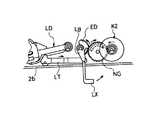
そのため、このギヤG2と歯合するギヤG3の大径ギヤ部G3aは、記録ヘッドHD等とプラテンP1等との間の圧接及び離間用の駆動力の伝達のため、そのギヤG3の小径ギヤ部G3b、スライド可能なスライドギヤSG、第1のかさ歯車付きギヤK1、第2のかさ歯車付きギヤK2、伝達遅延部としての二枚重ねの歯車NG、扇形ギヤED等からなる回動伝達手段SDを介して、前記駆動軸SN1の回動を伝達することができる(図6、20、21参照)。その結果、駆動軸SN1の正転または逆転は、ローラ・リリースロッドLTを左右に往復移動させ(図21(a)(b)(c)参照)、ローラホルダLDに支持されるプラテンP1及びテープ貼合せローラP3を、記録ヘッドHD及びテープ駆動ローラTC6に対して、それぞれ圧接及び離間させることができる。
【0084】
更にプラテンP1等を記録ヘッドHD等に圧接及び離間させる構造について、図21を参照して詳述すると、前記ローラホルダLDは、その先端側にプラテンP1及びテープ貼合せローラP3を回動自在に支持するとともに、その基端側で回動軸LD1によって、キャリッジCAに対して密接及び離間するように回動可能に支持されている。そのローラホルダLDの下面側には、ローラ・リリースロッドLTの先端部に回転ローラを備えたカム部LT1が当接しており、ローラ・リリースロッドLTが左方に向かって移動する(図21(b)参照)と、そのカム部LT1がローラホルダLDを押し上げて、プラテンP1とテープ貼合せローラP3とを、また、記録ヘッドHDとテープ駆動ローラTC6とをそれぞれ圧接させることができる(図21(c)参照)。それに対し、ローラ・リリースロッドLTが右方に向かって移動すると、そのカム部LT1がローラホルダLDの下面側を押し上げずに、ローラホルダLDは自重で下がるため、ローラホルダLDの先端側をキャリッジCAに対して離間させることができる(図21(a)参照)。
【0085】
そのローラ・リリースロッドLTは、その基端側に連結された揺動レバーLBの先端部LB1が、図21の左右に揺動することによって、左右方向に移動されるように構成されている。即ち、この揺動レバーLBの先端部LB1の揺動は、揺動レバーLBの基端部LB2が、第1のかさ歯車付きギヤK1、第2のかさ歯車付きギヤK2、二枚重ねの歯車NGを介して、駆動軸SN1の正転または逆転の駆動力の伝達を受けた扇形ギヤEDと一体的に回動することにより行われる。具体的には、第2のかさ歯車付きギヤK2が、反時計回り(もしくは時計回り)して、二枚重ねの歯車NGが、時計回り(反時計回り)し、更に、扇形ギヤEDが、反時計回り(時計回り)することにより、揺動レバーLBの先端部LB1が、図21の右方向(左方向)に移動し、更にはローラ・リリースロッドLTが、図21の右方向(左方向)に移動する。もっとも、回動伝達手段SDの態様は、必ずしも上記実施の形態に限定されるわけではなく、例えば、上記ギヤトレイン等とは異なった態様を採用してもよい。
【0086】
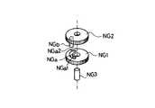
また、その回動伝達手段SDは、前記駆動軸SN1を一方向へ回転(正転)させて、前記圧接動作をした後に、駆動軸SN1を前記反対方向(逆転)へ回転させることにより、前記離間動作する際に、前記駆動軸SN1の反対方向への回転を直ちに伝達させずに、所定時間その伝達を遅延する伝達遅延部としての2枚重ねの歯車NGを備えている。
【0087】
この伝達遅延部は、2枚の歯車NGを、図22に示されるように、その回転軸NG3が相互に一致するように重ね合わせ、一方の歯車NG1の側面に摺動用の空間部としての長孔NGaを設けるとともに、他方の歯車NG2の側面に、その長孔NGaに嵌合する突部NGbを設けてなる。そのため、この突部NGbが、前記長孔NGaの内側の両端部NGa1、NGa2の間を摺動している状態では、前記駆動モータとしてのステップモータSNの駆動軸SN1が、前記反対方向へ回転しても、その回転を直ちに伝達させない。
【0088】
具体的には、前記歯車NG2が図21の紙面手前側に位置し、歯車NG1が図21紙面向こう側に位置するようにして相互に重ねられており、2枚の歯車NGの中心の貫通孔を前記回転軸NG3が貫通するので、歯車NG1、NG2はそれぞれ前記回転軸NG3を回転中心として回動できる。そして、前記歯車NG1は、図6に示されるように、前記扇形ギヤEDとのみ歯合するのに対し、歯車NG2は、第2のかさ歯車付きギヤK2の基端側ギヤ部K2aとのみ歯合する。
【0089】
そのため、第2のかさ歯車付きギヤK2によって、歯車NG2が回転させられ、長孔NGaの内側に嵌め込まれた突部NGbが、長孔NGaの両端部NGa1、NGa2の間を摺動している状態では、前記ステップモータSNの駆動軸SN1が、前記反対方向へ回転しても、歯車NG2は歯車NG1を回転させることなく、駆動軸SN1の回転を直ちに扇形ギヤEDに伝達させない。そして、突部NGbが、長孔NGaの両端部NGa1、NGa2の内のいずれか一方の端部NGa1、NGa2と当接した直後から、歯車NG2は歯車NG1を回転させ始め、駆動軸SN1の回転を扇形ギヤEDに伝達させる。
【0090】
それにより、前記伝達遅延部が動作している所定時間、即ち、突部NGbは、長孔NGaの両端部NGa1、NGa2の間を摺動している時間、前記駆動軸SN1による駆動が直ちに伝達されず、前記回動伝達手段SDにおける駆動の伝達が解除される。そのため、ステップモータSNのディテント・トルクもしくはギヤK1、K2、NG、ED等相互間にかかる負荷等がなくなったり、もしくは小さくなる。もっとも、伝達遅延部の態様は、必ずしも上記実施の形態に限定されるわけではなく、上記とは異なった態様を採用してもよく、例えば、機械部材を相互に組み合わせた回動伝達手段SDに、前記伝達遅延部に対応する「いわゆる遊び」及び「駆動軸による駆動が直ちに伝達されない不感帯分」を機械的あるいは電気的に設けてもよいし、それ以外の構成を採用してもよい。
【0091】
また、ローラリリースロッドLTのカム部LT1は、図2や図21における左方向に移動すると、ローラホルダLDと本体フレーム2の底面2bとに挟まれた状態になり、この状態において、前記プラテンP1及びテープ貼合せローラP3を、記録ヘッドHD及びテープ駆動ローラTC6に対して相互に圧接させた状態に保つ保持手段としての役割を果たしているので、ステップモータSNを回転し続けることなく、プラテンP1等と記録ヘッドHD等との圧接を保つことができ、記録ヘッドHDは、プラテンP1及び記録ヘッドHDの間で支持される被記録媒体D1に記録することができる。そのため、図21(c)において、前記駆動軸SN1を前記反対方向へ回転して、前記突部NGbが長孔NGaの記録ヘッドHD側の一端からステップモータSN側の他端へ移動するように、ステップモータSNの動作を制御するのが望ましい。
【0092】
前記プラテンP1等と記録ヘッドHDとを相互に圧接させた状態を解除して、プラテンP1等と記録ヘッドHDとを相互に離間させる操作部(図示せず)が、本体フレーム2裏側の外側から操作できる位置に設けられている。もっとも、前記操作部は、必ずしもこの態様に限った訳ではなく、図23に示されるように、例えば、操作用レバーLXとして、前記ロッドLTの基端側に取り付けてもよい。それにより、前記突部NGbが長孔NGaの上記他端へ移動した状態で、操作用レバーLXの先端側を摘んで回動させれば、前記回転伝達手段SDにおける駆動の伝達は解除されているので、ステップモータSNのディテントトルク、もしくはギヤK1、K2、KG等の相互間にかかる負荷等が無くなったり、もしくは小さくなっているので、小さな力で容易にプラテンP1等と記録ヘッドHD等とを相互に離間させることができる。
【0093】
次に、用紙送りローラ部JR1、JR2等を回動させる態様について説明する。スライドギヤSGは、スプリングバネSB1、SB2、切替用レバーKBの作用により図19、20の左右方向にスライドして、小径ギヤ部G3bと選択的に歯合することができる。ギヤG3の大径ギヤ部G3aは、ワイドステーションWS時における用紙送り用の駆動力を伝達すべく、前記ギヤG3の小径ギヤ部G3b、スライドギヤSG、前記長辺側シャーシHS2に沿って並設された用紙送り用の第1のギヤY1〜第7のギヤY7等を介して、ステップモータSNの回動を伝達し、用紙送りローラ部JR1、JR2等を回動させる。このようにスライドギヤSGを図19、20の左右方向にスライドさせて、ワイドステーションWS時における用紙送り用の駆動力として使用したり、テープステーションTS時における記録ヘッドHD等及びプラテンP1等間の圧接及び離間させたりして、駆動源としてのステップモータSNの駆動力を有効に活用する。
【0094】
更に詳述すると、前記長辺側シャーシHS2から短辺側シャーシHS1に向かって突き出ている回動軸HS3には、二つのギヤ、即ち、前記ギヤG3及び用紙送り用の第2のギヤY2が、その軸方向に並んで回動可能に取り付けられており、短辺側シャーシHS1に近接するギヤG3は、大径ギヤ部G3a及び小径ギヤ部G3bが一体として形成されているのに対し、長辺側シャーシHS2に近接する用紙送り用の第2のギヤY2は、平板状となっている。そして、ギヤG3の側方には、駆動力を切り替えるためのスライドギヤSGが設けられ、このスライドギヤSGは、ギヤG3の小径ギヤ部G3bと歯合した状態で、長辺側シャーシHS2から短辺側シャーシHS1に向かって突き出ている支持軸HS4に沿ってスライド可能となっている。
【0095】
この支持軸HS4には、長辺側シャーシHS2から短辺側シャーシHS1に向かって、押圧スプリングSB1、スライドギヤSG及びスライド部材F1がその順番に取り付けられ、この押圧スプリングSB1が、スライドギヤSG及びスライド部材F1を、長辺側シャーシHS2から短辺側シャーシHS1に向かって付勢している。また、長辺側シャーシHS2の後方側には、支持軸HS5がワイドステーションWS側からテープステーションTS側に向かって延設されており、この支持軸HS5の先端側の止め具HS6が、スライド部材F1及び押圧スプリングSB2を支持軸HS5に取り付けることにより、押圧スプリングSB2は、スライド部材F1をワイドステーションWS側に付勢している。
【0096】
そして、複数の押圧スプリングSB1、SB2、及び、次に述べる切り替えレバーKBの作用により、前記スライド部材F1がスライドギヤSGを長辺側シャーシHS2側もしくは短辺側シャーシHS1側に近接するように移動して、第1のかさ歯車付きギヤK1もしくは第1のギヤY1のいずれか一方に歯合するようになっている。
【0097】
前記切り替えレバーKBは、スライドギヤSGを、第1のかさ歯車付きギヤK1もしくは第1のギヤY1のいずれか一方に歯合させるための構成要素であって、図24に示されるように、左方側から第1、第2、第3の腕部KB1、KB2、KB3を有する切り替えレバーKBが、長辺側シャーシHS2に取り付けられた軸KB4の回りに回動可能に取り付けられている。この切り替えレバーKBは、スライド部材F1に当接して、スライド部材F1とともにスライドギヤSGを、長辺側シャーシHS2(即ちワイドステーションWS)側、または短辺側シャーシHS1(即ちテープステーションTS)側へ移動可能とする。
【0098】
即ち、キャリッジCAがテープステーションTSに位置する時は、図24の実線に示されるように、第1、第2の腕部KB1、KB2が、軸KB4の回りにテープステーションTS側に向かって倒れた状態で、第3の腕部KB3が立ち上がった状態にあり、第1の腕部KB1の先端部がスライド部材F1を押圧して、テープステーションTS側に移動させた状態にある(図20参照)。それに対し、キャリッジCAがワイドステーションWSに位置する時は、図24の仮想線で示されるように、第1、第2の腕部KB1、KB2は立ち上がった状態にあるとともに、第3の腕部KB3は、ワイドステーションWS側に向かって倒れた状態で、前述のごとく第1の腕部KB1の先端部がスライド部材F1を押圧せずに、スプリングバネSB2によって、スライド部材F1を長辺側シャーシHS2(ワイドステーションWS)側へ移動させ、第1の腕部KB1に当接することになる(図19参照)。
【0099】
そして、キャリッジCAがテープステーションTSからワイドステーションWSへ移動(図24の実線から仮想線へ移動)する際、キャリッジCAの切替作用部としての突起CP1が第3の腕部KB3の側部に当接して、切り替えレバーKBはワイドステーションWS側に押し倒されて、軸KB4の回りにほぼ90度回転し、第1の腕部KB1の先端部とスライド部材F1との係合を外す。それに対し、キャリッジCAがワイドステーションWSからテープステーションTSへ移動(図24の仮想線から実線への移動)する際に、キャリッジCAの突起CP1が、第2の腕部KB2の側部に当接して、切り替えレバーKBはテープステーションTS側に押し倒させて、軸KB4の回りにほぼ90度回転し、第1の腕部KB1の先端部とスライド部材F1とを係合させる。
【0100】
それにより、切り替えレバーKB及び第1の押圧スプリングSB1の作用の下、スライド部材F1を短辺側シャーシHS1(テープステーションTS)側へ移動することによって(図20参照)、スライドギヤSGがギヤG3の小径ギヤ部G3bと歯合する。その結果、スライドギヤSGは、第1のかさ歯車付きギヤK1と歯合して、テープステーションTS時における記録ヘッドHD及びローラホルダ等の間の圧接及び離間用の駆動力を前述のごとく伝達する。
【0101】
一方、切り替えレバーKB及び第2の押圧スプリングSB2の作用の下、スライド部材F1が、長辺側シャーシHS2(ワイドステーションWS)側へ移動することによって(図19参照)、スライドギヤSGが、第2のギヤY2の側方に配置された第1のギヤY1と歯合する。その結果、ワイドステーションWS時における用紙送り用の駆動力を、ギヤトレインとしての第2のギヤY2〜第7のギヤY7等へと伝達することができる。
【0102】
具体的には、第1のギヤY1は、スライドギヤSGと歯合する大径部Y1a及びこの大径部Y1aの長辺側シャーシHS2側の小径部Y1bからなり、その小径部Y1bが、用紙送り用のローラ部JR2の軸部JR2bの端部に取り付けられギヤJR2cと歯合し、被記録媒体D2の先端部を前後に搬送するように、ローラ部JR2の軸部JR2bを回動する。また、第1のギヤY1の大径部Y1aは、前記第2のギヤY2と歯合し、更に、第2のギヤY2は、このギヤY2の側方(図19、20の紙面上方)に取り付けられた第3のギヤY3と歯合し、この第3のギヤY3は、このギヤY3の側方(図19、20の紙面上方)に取り付けられた第4のギヤY4と歯合する。
【0103】
第4のギヤY4は、このギヤY4の側方(図19、20の紙面上方)に取り付けられた第5のギヤY5と歯合し、この第5のギヤY5は、このギヤY5の側方(図19、20の紙面左方)に取り付けられた第6のギヤY6と歯合する。この第6のギヤY6は、このギヤY6の側方(図19、20の紙面手前)に取り付けられた第7のギヤY7と歯合するが、この第7のギヤY7は、前記第6のギヤY6と歯合する大径部Y7a及びこの大径部Y7aの長辺側シャーシHS2側の小径部Y7bからなる。そして、その小径部Y7bが、用紙送り用のローラ部JR1の軸部JR1bの端部に取り付けられギヤJR1cと歯合し、被記録媒体D2の先端部を前後に搬送するように、ローラ部JR1の軸部JR1bを回動する。
【0104】
尚、第7のギヤY7の大径部Y7aの側方(図3の紙面上方)には、前記支持用突起ST1を回動させるため、支持用突起ST1と一体的に回動するギヤST3と前記大径部Y7aとを連結するギヤST4が設けられており、前記支持用突起ST1は、ステップモータSNの回動を受けて、巻装状態の被記録媒体D2の先端部を巻戻したり、あるいは引き出したりする。
【0105】
それにより、この実施の形態においては、スプリングバネSB1、SB2、切替用レバーKB、当接部材としての突起CP1が、切り替え手段を構成するが、必ずしもこの態様に限ったわけではなく、他の態様を採用しても良い。
【0106】
次に、記録装置の一例としてのテープ印字装置1の制御系について図14に基づいて説明する。図14において、テープ印字装置1の制御装置CPは、中央制御装置(以下CPUという)を中核として構成されており、そのCPUには、読み出し専用メモリ(以下ROMという)及び読み書き自在メモリ(以下RAMという)が内蔵されている。ROMには、モータSL、SM、SNの駆動制御プログラム、キーボード3の各キーを介して入力された文字等をディスプレイ5に表示させる表示プログラム、その他テープ印字装置1の操作上必要な各種のプログラム等が記憶されている。尚、前記CPUに接続されるCG−ROMは、文字等の表示時や印字時にそのイメージデータを発生するためのキャラクタジェネレータである。一方、RAMには、表示バッファ、印字バッファ等の各種のデータ記憶領域が設けられており、この種のデータが一時的に記憶される。
【0107】
また、モータ駆動回路SLk、SMk、SNkは、前記ステップモータSL、SM、SNを駆動するための回路である。更に、上述した各種センサSQ、SY、SE、SZ等は、既述したごとく、キャリッジCAの存在の有無、カセットTC、RCの装着の有無、被記録媒体D1、D2の種類、幅、存在の有無等を検出し、その信号をCPUに送出する。また、記録ヘッドHDは、記述した如く、列状に形成された多数の発熱素子を有しおり、CPUを介して各発熱素子を選択的に発熱駆動することによりインクリボンIRを介して被記録媒体D1、D2上に文字等の印字を行うことができる。
【0108】
以上詳述した如く、この実施の形態のテープ印字装置1によれば、記録素子を少なくとも一方向に列設した記録ヘッドHDと、この記録ヘッドHDに対して、長尺状の被記録媒体D2の先端部を前記列設方向に搬送させるステップモータSN、ギヤトレインGYと、被記録媒体D2の搬送方向における記録ヘッドHDの下流側に配設され、その被記録媒体HDを切断する切断装置KCとを備えており、記録素子の配列(L1)分単位で被記録媒体D2の先端部を搬送させ、その搬送の停止状態で、記録ヘッドHDが記録動作を行う。そして、制御装置CPは、前記切断装置KCの切断動作の直前における被記録媒体D2の搬送量(L3)を、記録素子の配列(L1)分より少なくし、切断装置KCの切断動作を行った後に、残りの搬送量(L4)だけ搬送した状態で、前記記録ヘッドHDが記録を行うを有する。それにより、被記録媒体D2における切断前に記録した部分と切断後に記録した部分との間に、ホワイトラインとか、もしくは、著しい記録の重なりとかが生じることを防止でき、切断前に記録した部分と切断後に記録する部分とがきれいにつながって、被記録媒体D2には鮮明な記録ができる。
【0109】
尚、本発明は前記実施の形態に限定されるものではなく、本発明の要旨を逸脱しない範囲において種々の変形、改良が可能であることは勿論である。例えば、ライン記録モードでは、被記録媒体ID及びインクリボンIRを収納する第1のカセットTCを使用し、シリアル記録モードでは、インクリボンIRのみを収納する第2のカセットRCを使用しているが、必ずしもこの態様に限定される訳ではなく、例えば、被記録媒体IDのみを収納するカセットTCを使用してもよい。また、第2のカセットRCが収納するインクリボンIRは、複数色のインクが順番に塗布されているインクリボンである必要はなく、例えば、単色のインクリボンであってもよい。また、駆動モータとしては、ステップモータ以外のモータを使用してもよい。
【0110】
また、被記録媒体D1を搬送するためのステップモータSLを、シリアル記録モードにおける、記録ヘッドHDと被記録媒体D2との間の圧接及び離間のために使用すること、もしくは、被記録媒体D2を搬送するためのステップモータSNを、ライン記録モードにおける、記録ヘッドHDと被記録媒体D1との間の圧接及び離間のために使用することは、望ましい態様であるが、必ずしもその態様に限定される訳ではない。また、第1のプラテンP1は、円筒状に形成され、前記第2のプラテンP2は、被記録媒体D2の支持する面が平面状に形成されているのが好ましいが、その態様でなくてもよい。
【0111】
また、幅広の被記録媒体D2を巻装した状態で保持するカセットHS0(図4参照)は、例えば、用紙送り出し口内側に、送りローラを設けてもよい。また、プラテンと駆動ローラとは、前記実施の形態では、別の部材であったが、同一部材からなっていてもよい。更には、プラテンもしくは駆動ローラのいずれか一方のみ、または、双方を備えていてもよい。
【0112】
また、本発明の記録装置は、必ずしもテープ印字装置である必要はなく、例えば、一般的なサーマルプリンター等の他、被記録媒体として感熱性孔版原紙、多孔性樹脂板等をスタンプの版下として用いる記録装置であってよい。また、記録ヘッドは、サーマルヘッド以外であってもよい。
【0113】
【発明の効果】
請求項1に記載された記録装置によれば、記録素子を少なくとも一方向に列設した記録ヘッドと、この記録ヘッドに対して、長尺状の被記録媒体の先端部を前記列設方向に搬送させる搬送手段と、前記被記録媒体の前記搬送方向における記録ヘッドの下流側に配設され、その被記録媒体を切断する切断装置とを備え、前記記録素子の列設長さとほぼ同じ長さ分単位で被記録媒体の先端部を搬送させ、その搬送の停止状態で、記録ヘッドが記録動作を行う記録装置において、前記切断装置の切断動作の直前における被記録媒体の搬送量を、前記記録素子の列設長さとほぼ同じ長さ分より少なくし、切断装置の切断動作を行った後に、残りの搬送量だけ搬送した状態で、前記記録ヘッドが記録を行う制御手段を有するので、切断装置のカッター等によって被記録媒体が引っ張られて、被記録媒体の搬送機構に用いられているギヤトレイン中にバックラッシュが生じても、残りの搬送量だけ搬送する際に、そのバックラッシュ分だけ調整すればよい。それにより、被記録媒体における切断前に記録した部分と切断後に記録する部分との間に、ホワイトラインとか、もしくは、著しい記録の重なりとかが生じることを防止でき、切断前に記録した部分と切断後に記録する部分とがきれいにつながって、被記録媒体には鮮明な記録ができる。
【0114】
また、請求項2に記載された記録装置によれば、被記録媒体の裏面側には、片面に剥離紙を重ね合わせた両面粘着テープが貼付けられているので、剥離紙を両面粘着テープから剥せば、例えば、ファイルの背表紙等の被貼付物に、その両面粘着テープを介して、被記録媒体を容易に貼付けることができる。
【0115】
また、請求項3に記載された記録装置によれば、記録素子は、発熱素子であって、その列設方向に交差する方向に、記録ヘッドを往復搬送するヘッド搬送手段を設けたので、記録ヘッドが幅広の被記録媒体に対して記録素子の列設方向と交差する方向に往復搬送し、発熱素子が選択的に発熱すれば、シリアル記録モードで幅広の被記録媒体に記録することができる。
【図面の簡単な説明】
【図1】本発明に係る記録装置の一実施の形態であるテープ印字装置の外観図である。
【図2】図1に示すテープ印字装置の内部構造を示す正面図である。
【図3】図1に示すテープ印字装置の内部構造を示す平面図である。
【図4】前記テープ印字装置における幅広の被記録媒体と記録へッドとの位置関係を示す図である。
【図5】図2のテープステーションの一部を拡大して示す正面図である。
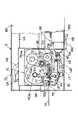
【図6】図3のテープステーションの一部を拡大して示す平面図である。
【図7】この実施の形態のテープカセットを示す拡大正面図である。
【図8】この実施の形態のリボンカセットを示す拡大正面図である。
【図9】この実施の形態のキャリッジを示す拡大正面図である。
【図10】図9のキャリッジ上に取り付けられた主要部品を、I−I線側からみた側面図である。
【図11】図9のキャリッジ上に取り付けられた主要部品を、II−II線側からみた側面図である。
【図12】図9のキャリッジ上に取り付けられた主要部品を、III−III線側からみた側面図である。
【図13】図9のキャリッジ上に取り付けられた主要部品を、IV−IV線側からみた側面図である。
【図14】この実施の形態のテープ記録装置の制御構成を示すブロック図である。
【図15】図9のキャリッジからギヤ等を取り除いた状態であって、記録ヘッドがプラテンに圧接される状態を示す拡大正面図である。
【図16】図9のキャリッジからギヤ等を取り除いた状態であって、記録ヘッドがプラテンに離間される状態を示す拡大正面図である。
【図17】この実施の形態のヘッド駆動カムギヤを示す拡大正面図である。
【図18】図17のヘッド駆動カムギヤの一部と、ギヤと関係を拡大して示す正面図である。
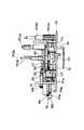
【図19】この実施の形態の幅広の被記録媒体の搬送、及び、記録ヘッドと第1のプラテンとを圧接・離間するための主要部品を示す拡大平面図である。
【図20】この実施の形態の幅広の被記録媒体の搬送、及び、記録ヘッドと第1のプラテンとを圧接・離間するための主要部品を示す拡大平面図である。
【図21】この実施の形態の記録ヘッドとプラテンとを圧接・離間する際の、相対的な位置関係を示す図である。
【図22】この実施の形態の伝達遅延部を分解して示す斜視図である。
【図23】この実施の形態の記録ヘッドからプラテンを離間させるための操作部材の他の実施例を示す正面図である。
【図24】この実施の形態のキャリッジの移動と切り替えレバーとの関係を示す図である。
【符号の説明】
1 テープ印字装置(記録装置)
HD 記録ヘッド
D1 幅狭の被記録媒体(被記録媒体)
CH ヘッド搬送手段
D2 幅広の被記録媒体(被記録媒体)
SN ステップモータ(搬送手段)
R1、R2 搬送ローラ部(搬送手段)
GY ギヤトレイン(搬送手段)
KC 切断装置
CP 制御装置(制御手段)
L3、L4 搬送量
L1 配列分(列設長さ分)[0001]
BACKGROUND OF THE INVENTION
The present invention relates to a recording apparatus that records characters and marks such as characters on a recording medium, and more particularly to a recording apparatus that cuts and uses a long recording medium.
[0002]
[Prior art]
Conventionally, this type of recording apparatus includes a platen that supports a recording sheet conveyed to the recording head, and a cutting device that cuts the recording sheet disposed on the downstream side of the platen. After the recording head records on the recording paper, the recording paper is conveyed to the cutting device side, the cutting device is operated, and the recording paper is cut.
[0003]
[Problems to be solved by the invention]
However, when the cutting device operates to cut the recording paper, the recording paper is pulled by a cutter of the cutting device, and backlash may occur in the gear train used in the recording paper transport mechanism. is there. Therefore, when the recording head operates on the recording paper after recording on the recording paper and performs recording on the recording paper again, between the part recorded before cutting and the part recorded after cutting, a so-called white line, or There may be significant recording overlap.
[0004]
The present invention has been made in order to solve the above-described problem, and a white line or a significant overlap of recording between a recorded part of a recording medium before cutting and a recorded part after cutting. An object of the present invention is to provide a recording apparatus capable of preventing the occurrence of slack.
[0005]
[Means for Solving the Problems]
In order to achieve the above object, according to the recording apparatus of the first aspect of the present invention, there is provided a recording head in which recording elements are arranged in at least one direction, and a recording medium that is long with respect to the recording head. A transport unit that transports the front end portion in the row direction; and a cutting device that is disposed on the downstream side of the recording head in the transport direction of the recording medium and cuts the recording medium. In a recording apparatus in which the leading end portion of the recording medium is transported in units substantially the same as the arrangement length, and the recording head performs a recording operation in the stopped state, the recording target immediately before the cutting operation of the cutting apparatus The recording head performs recording in a state where the conveyance amount of the medium is less than the length substantially equal to the line arrangement length of the recording elements, and after the cutting operation of the cutting device, the remaining conveyance amount is conveyed. With control means And wherein the door.
[0006]
Thereby, the control means reduces the conveyance amount of the recording medium immediately before the cutting operation of the cutting device by less than the same length as the row length of the recording elements, and after performing the cutting operation of the cutting device, Since the recording head controls to perform recording in the state where the remaining transport amount is transported, the recording medium is pulled by a cutter of the cutting device, etc., during the gear train used for the transport mechanism of the recording medium Even if backlash occurs, when the remaining amount of conveyance is carried, it is only necessary to adjust the amount corresponding to the backlash. Accordingly, it is possible to prevent a white line or a significant recording overlap between a portion recorded before cutting on the recording medium and a portion recorded after cutting.
[0007]
According to the recording apparatus of the invention relating to
[0008]
According to the recording apparatus of the invention of
[0009]
DETAILED DESCRIPTION OF THE INVENTION
Hereinafter, embodiments of the present invention will be described with reference to the drawings.
As shown in FIG. 1, the recording apparatus of the present embodiment is a
[0010]
On the
[0011]
A cover case 7 that can be opened and closed is provided on the front side of the
[0012]
2 and 3 are a front view and a plan view showing the main part of the recording mechanism inside the
[0013]
On the other hand, recording is performed in the serial recording mode in the wide station WS. In this serial recording mode, the recording head HD is conveyed in the main scanning direction (that is, the horizontal direction in FIGS. 2 and 3) that intersects the conveying direction of the wide recording medium D2 (that is, the direction from the upper side to the lower side in FIG. 3). Then, the recording head HD performs recording on the recording medium D2, and after the recording is completed, the recording medium D2 is transported by a predetermined amount in the transport direction, and recording is performed while transporting again in the main scanning direction.
[0014]
Specifically, as shown in FIG. 4B, the carriage transport mechanism CH reciprocates the carriage CA in the main scanning direction intersecting the transport direction of the wide recording medium D2, as shown in FIG. Performs recording in the main scanning direction of the recording medium D2 (as shown in the lines “A”, “I”, “U”, “E”, “O”, and “KA”, “KI”, “KU”, “KE”). After the recording is completed, the conveyance mechanism QH of the wide recording medium D2 moves the recording medium D2 by a predetermined amount in the conveyance direction from the upper side to the lower side in FIG. (Refer to FIG. 4A)), that is, the sheet is transported by the same length as the array length of the recording elements. Then, the carriage transport mechanism CH transports the carriage CA in the main scanning direction of the recording medium D2 again, whereby the recording head HD records on the recording medium D2 (as shown in the figure, “sa” “su” “shi”). “Set” and “So” are recorded), and the same manner is repeated.
The transport amount of the recording medium D2 can be set to be smaller by one to several heating elements than the arrangement amount L1 of the heating elements. In this case, the rear end of the recording result of the first row and the front end of the recording result of the second row in the transport direction of the recording medium D2 are recorded by overlapping one heating element (dot) to several (several dots). As a result, there is no gap between the trailing edge of the first line recording result and the leading edge of the second line recording result. However, considering the recognition ability of the human eye, there is no problem with such a degree of recording overlap, so the transport amount of the recording medium D2 is the same length as the length L1 of the heating elements. Alternatively, the number of heating elements can be set to be one to several less than that. Therefore, the recording medium D2 is transported by a length substantially the same as the arrangement length of the heating elements.
[0015]
The carriage transport mechanism CH includes a step motor SM installed at the right end inside the
[0016]
Accordingly, when the step motor SM is driven forward or reversely, the drive pulley SP2 rotates in one direction or the opposite direction via the drive shaft SM1 and the drive gear portions SM2 and SM3, and the timing belt TB is unidirectionally or oppositely driven. Move in the direction. Therefore, as the timing belt TB is moved, the carriage CA on which the recording head HD is mounted is stepped between the pulleys SP1 and SP2 along the guide axis GD in the left and right directions in FIGS. As shown by the solid line in FIGS. 2 and 3, it is arranged at the tape station TS, or as shown by the two-dot chain line in FIGS. 2 and 3, the recording area of the wide station WS is reciprocated. Incidentally, since the control pulse amount of the step motor SM and the feed amount of the timing belt TB correspond exactly, the control device CP shown in FIG. 14 applies the control pulse to the step motor SM by a predetermined amount. If sent, the timing belt TB is sent by a predetermined amount, and the carriage CA is accurately transported.
[0017]
The transport mechanism QH for the wide recording medium D2 includes support protrusions ST1 and ST2 that support the recording medium D2 mounted on the rear side inside the
[0018]
In this case, a compression spring AB is attached to the supporting projection ST1 on the bottom chassis HS side so as to urge the projection ST1 toward the chassis KS. On the other hand, the support protrusion ST2 on the chassis KS side is movable toward the support protrusion ST1 side on the bottom chassis HS side so as to correspond to the paper width of the recording medium D2, for example, FIG. 3, even if the recording medium D2 has a different paper width, both the support protrusions ST1 and ST2 reliably keep the recording medium D2 in a wound state, even if the recording medium D2 has a different paper width. The leading end side of D2 can be sent out in the direction of the paper feed roller portions JR1 and JR2.
[0019]
These roller portions JR1 and JR2 are rotatably mounted between the long side chassis HS2 in the bottom surface side chassis HS and the chassis KS on the wide station WS side. Further, a step motor SN is fixed to the tape station TS side of the short side chassis HS1 in the bottom side chassis HS. Therefore, the forward or reverse driving force of the motor SN is transmitted through gears Y1 to Y7, ST3, ST4, etc. constituting the paper feed gear train GY arranged in parallel along the long side chassis HS2. As a result, the support protrusion ST1 and the roller portions JR1 and JR2 rotate clockwise or counterclockwise.
[0020]
The roller portions JR1 and JR2 are formed by attaching a plurality of paper feed rollers JR1b and JR2b to a pair of upper and lower roller shafts JR1a and JR2a, respectively. Therefore, when the rollers JR1b and JR2b are pressed against each other, the leading end of the wound recording medium D2 is sandwiched between the rollers JR1b and JR2b, and the rollers JR1b and JR2b rotate. The medium D2 is conveyed toward the front side so as to be pulled out, or is conveyed toward the rear side so as to be rewound.
[0021]
Further, a second platen P2 is provided on the bottom surface side through which the recording head HD between the paper feed roller portions JR1 and JR2 passes. The surface of the platen P2 that supports the recording medium D2 is substantially flat. Is formed. In this case, if a cylindrical platen is used for the second platen P2, the heating element that performs recording of the recording head HD is orthogonal to the cylindrical platen, so that the upper and lower ends of the heating element of the recording head HD are cylindrical. Insufficient pressure contact with the platen tends to cause the recording result to be wrinkled or missing. Accordingly, if the second platen P2 is formed in a substantially flat plate shape, such a situation can be prevented. Therefore, it is desirable to use a planar platen rather than a cylindrical platen.
[0022]
A sensor mark SX is provided on the upper surface of the side of the platen P2 (left side in FIG. 3). This mark SX is recorded on the wide station WS side when the recording head HD reciprocates in the left-right direction. Used to detect the moving origin of the head HD. That is, when the control device CP sends a control pulse by a predetermined amount to the step motor SM and performs recording while moving the recording head HD in the main scanning direction, the origin of movement on the wide station WS side by the mark SX is recorded. It becomes a reference for the position control of the head HD.
[0023]
Specifically, the mark SX is composed of two patterns having alternately reflective and non-reflective areas, and a reflective sensor (not shown) mounted on the carriage CA is pasted on the platen P2. The mark SX is detected as the target. Then, the control device CP determines the position where the reflective sensor has detected the change point where the reflective state changes to the non-reflective state twice. This is because, if there is one change point, and there is a white recording medium D2 with respect to the black platen, the control device CP determines that the boundary between the paper and the platen is a change point and erroneously detects it. . In order to prevent such erroneous detection, it is desirable to provide the sensor mark SX having the two patterns as described above.
[0024]
In addition, a detection sensor SW for detecting the leading end of the recording medium D2 is provided in the vicinity of the downstream side of the roller portion JR2, and the conveyance control of the recording medium D2 is performed based on the output signal of the sensor SW. Is called. For example, the user sets the recording medium D2 at a predetermined position on the rear side inside the
[0025]
Further, a cutting device KC for cutting the recording medium D2 is provided on the downstream side of the roller portion JR2, and this cutting device KC operates at a predetermined timing under the conveyance control of the recording medium D2. By doing so, the recording medium D2 is cut. The cutting device KC may be, for example, a type in which the blade portion KC1 (see FIG. 4) reciprocates in the width direction of the recording medium D2 (left and right direction in FIG. 3) and cuts. In addition, the blade portion KC1 may be of a type in which the blade span is equal to the width of the recording medium D2 and is moved up and down to cut the recording medium D2, as long as the recording medium D2 can be cut.
[0026]
In order to prevent a white line or significant recording overlap between the portion recorded before cutting and the portion recorded after cutting in the recording medium D2, the control device CP performs the following control. I do. That is, as clearly shown in FIG. 4A, the control device CP normally conveys the leading end of the medium D2 in units of the heating element arrangement (L1), and the recording head HD performs the recording operation in the stopped state. However, the transport amount (L3) of the recording medium D2 immediately before the cutting operation of the cutting device KC is made smaller than the arrangement of the heating elements (L1). Then, after the cutting operation of the cutting device KC is performed, the remaining transport amount L4 (= L1-L3) is transported, and the recording head HD performs recording.
[0027]
Specifically, the control device CP rotates the roller portions JR1 and JR2 to transport the leading end portion of the medium D2 in units of the heating element arrangement (L1), and in the stopped state, the carriage transport mechanism CH Is driven, the recording head HD performs a recording operation in the main scanning direction of the recording medium D2 via the ink ribbon IR. At this time, in the case of this embodiment, the control device CP determines whether or not the recording is performed before the second line for cutting the recording medium D2, and when the recording is not performed before the second line, as usual, The leading end of the medium D2 is transported in units of arrangement (L1). When the control device CP determines that the recording is performed before the second line in which the recording medium D2 is cut, the control device CP transports the transport amount (L3) smaller than the arrangement of the heating elements (L1) after the end of the recording. .
[0028]
Then, the control device CP performs the cutting operation of the cutting device KC to cut the leading end portion of the recording medium D2, and then transports the remaining transport amount L4 (= L1-L3) to perform the next recording. As a result, even if the recording medium D2 is pulled by the cutting device KC or the like and a backlash occurs in the conveyance gear train GY or the like of the recording medium D2, the remaining conveyance amount L4 (= L1-L3) is conveyed. Just adjust the backlash. Therefore, no white line or significant recording overlap occurs between the portion recorded before cutting and the portion recorded after cutting in the recording medium D2.
[0029]
However, since it is only dependent on the positional relationship between the cutting device KC and the recording head HD that the control device CP determines whether or not the recording is for the second line before the recording medium D2 is cut. It may be driven by the cutting device KC after the recording of other rows is completed. In particular, in the case of a mechanism in which the recording medium D2 is transported more than the backlash of the gear by driving the cutting device KC, the amount of transport beyond the backlash is grasped in advance and the cutting operation of the cutting device KC is performed. Adjustment may be made when the remaining transport amount is transported.
[0030]
Next, the structure of the carriage CA will be described. On the surface (mounting surface) side of the carriage CA, a tape cassette TC (see FIGS. 2, 5 and 7) containing a narrow recording medium D1 and an ink ribbon IR or the like, or only the ink ribbon IR is stored. The ink cassette RC (see FIG. 8) can be selectively placed, while a step motor SL (see FIGS. 3 and 6) is mounted on the back side thereof. The step motor SL is used for feeding the tape such as the ink ribbon IR in the cassette TC set on the carriage CA, and is pressed between the recording head HD and the wide recording medium D2 in the wide station WS. And used for spacing. The reason for using the step motor SL as a drive source for two applications in this way is to effectively utilize the drive force of the step motor SL.
[0031]
A recording head HD is attached to the lower side of the carriage CA, and a number of heating elements capable of generating heat in units of one dot are formed on the recording surface side of the recording head HD in a line at a predetermined distance (printing width L1 ( (See FIG. 4))). Then, a tape feed mechanism using a driving force such as a step motor SL crosses the recording medium (tape) D1 in the cassette TC placed on the carriage CA while intersecting the arrangement direction of the heating elements. Since the ink is conveyed to the recording surface side of the recording head HD, the heat generated by the heat generating element melts the ink of the ink ribbon IR, and the ink can adhere to the recording medium D1 in units of one dot.
[0032]
As shown in FIG. 7, the tape cassette TC is one in which a narrow recording medium D1 and an ink ribbon IR used at the time of the tape station TS are stored in a substantially rectangular cassette case. On the other hand, as shown in FIG. 8, the ribbon cassette RC is one in which a narrow ink ribbon IR used in the wide station WS is stored in a substantially rectangular cassette case. Unlike the tape cassette TC, The narrow recording medium D1 is not accommodated.
[0033]
Specifically, as shown in FIGS. 5 and 7, the tape cassette TC includes a narrow recording medium D1 made of, for example, a transparent tape, and ink for printing on the narrow recording medium D1. Ribbon IR, and further, a double-sided adhesive tape YT to be back-coated on a narrow recording medium D1 on which printing has been performed, are wound around reels TC1, TC2, and TC3, respectively. An ink ribbon take-up reel TC4 for taking up the ribbon IR is provided.
[0034]
Then, the narrow unused ink ribbon IR wound around the reel TC2 and drawn out from the reel TC2 is overlapped with the narrow recording medium D1, and together with the narrow recording medium D1, the opening TC5. Enters and passes between the recording head HD and the platen P1. Thereafter, the ink ribbon IR is separated from the narrow recording medium D1, reaches the take-up reel TC4 of the ink ribbon IR that is driven by the step motor SL, and is taken up by the reel TC4.
[0035]
In the state where the tape cassette TC is set on the carriage CA, a ribbon winding cam member PC4a protruding from the surface of the carriage CA is inserted into the reel TC4. A drive cam follower TC4b that is integrally driven with the reel TC4 is inserted inside. Therefore, the reel TC4 is rotated by receiving the driving force of the step motor SL via a gear train (described later) provided on the carriage CA under the engagement of the driving cam follower TC4b and the cam member PC4a. The used ink ribbon IR can be wound up.
[0036]
The double-sided pressure-sensitive adhesive tape YT is wound and stored on a reel TC3 with the release paper on the outer side, with the release paper superimposed on one side. The double-sided adhesive tape YT drawn from the reel TC3 passes between the tape driving roller TC6 and the tape laminating roller P3, and the adhesive surface on the side where the release paper is not superimposed is applied to the recording medium D1 having a narrow width. Affixed. Note that, also for the recording medium D2, it is desirable that a double-sided adhesive tape with release paper superimposed on one side is stuck to the back side of the medium D2.
[0037]
As a result, the narrow recording medium D1 wound around the reel TC1 and pulled out from the reel TC1 is passed through a pair of sensors SE for detecting the end or color detection, the guide pins TB1, and the like. It passes through the opening TC5 of the cassette TC. After that, the narrow recording medium D1 to which the double-sided adhesive tape YT is bonded is rotatably provided at the lower part on one side of the tape cassette TC, and the tape driving roller TC6 that rotates by receiving the drive of the step motor SL, It passes between the tape laminating roller P3 disposed opposite to the roller TC6, reaches the outside of the tape cassette TC, and is discharged from the
[0038]
The tape laminating roller P3 is supported by the roller holder LD along with the platen P1. Therefore, the roller holder LD can press and separate the tape driving roller TC6 and the tape laminating roller P3, and the recording head HD and the first platen P1 from each other. In this case, it is desirable that the first platen P1 can be rotated for transporting the recording medium D1, and therefore it is desirable to use a cylindrical platen.
[0039]
As shown in FIG. 7, the tape drive roller TC6 is provided with a through hole TC8, and a tape drive roller cam follower TC9 is formed in the through hole TC8. Therefore, when the tape driving cam member PC6b protruding from the front surface side of the carriage CA is inserted into the through hole TC8 (see FIG. 9), the tape driving cam member PC6b engages with the cam follower TC9. it can. On the other hand, a tape feeding cam member PC3a protruding from the surface of the carriage CA is inserted into the reel TC3. The reel TC3 rotates integrally with the reel TC3. Since the drive cam follower is not mounted and the cam member PC3a only idles, there is no influence on the feeding of the double-sided adhesive tape YT.
[0040]
Further, the ribbon cassette RC prints on the recording surface D2b of the wide recording medium D2 at the wide station WS (see FIG. 4), so that both ends of the ink ribbon IR are used for winding the unused ink ribbon. A reel RC1 and a reel RC2 for winding a used ink ribbon are wound and stored. Then, according to a ribbon winding mode, which will be described later, the ink ribbon IR drawn from the reel RC1 passes through the sensor SE and then passes through the guide member RB1 (see FIG. 8). Then, it passes through the opening RC3 of the ribbon cassette RC, and is further wound around the reel RC2 via the guide member RB2.
[0041]
In the state where the ribbon cassette RC is set on the carriage CA, the tape feeding cam member PC4a and the tape driving cam member PC6b protruding from the surface side of the carriage CA are inserted into the reels RC4 and RC5, respectively. However, unlike the case of the tape cassette TC, a drive cam follower that rotates integrally with the reels RC4 and RC5 is not mounted inside the reels RC4 and RC5. Therefore, the cam member PC4a and the tape driving roller TC6 that receive the driving force of the step motor SL only rotate idly, so there is no influence on the feeding of the ink ribbon IR, and it is not necessary to cut the driving.
[0042]
In the case of color, the ink ribbon IR in the ribbon cassette RC is, for example, a plurality of inks composed of cyan (C), magenta (M), yellow (Y), etc., in order for a certain length, that is, one line. Coating is performed in the length direction by the recording range of L2 (see FIG. 4B). This is because the recording head HD is conveyed to the recording medium D2 via the ink ribbon IR for one line of any one of magenta, cyan, and yellow while the recording head HD is conveyed in the main scanning direction of the recording medium D2. This is because, in addition to recording for one line L2, recording is performed for one line L2 with a color obtained by mixing these inks. (Note that the cross line in FIG. 4 (b) indicates a range in which the recording head HD performs main scanning and records for one line L2). In this case, after recording on the recording medium D2 for one line in any one color of magenta, cyan, and yellow, the recording head HD corresponds to one line in another color, and if necessary, one line in another color. By overlapping and recording at the same position on the recording medium D2 via the ink ribbon IR of the minute, in a mixed color of cyan (C), magenta (M), yellow (Y), for example, red, blue, etc. Can record.
[0043]
Differences between the tape cassette TC and the ribbon cassette RC include, as clearly shown in FIGS. 7 and 8, the presence or absence of the double-sided adhesive tape YT and the recording medium D1, and the reel for winding up the unused ink ribbon. The positions of TC2, RC1 and the positions of used ink ribbon take-up reels TC4, RC2 are greatly different. That is, the position of the reel TC1 for the recording medium D1 of the tape cassette TC is the position of the reel RC1 of the ribbon cassette RC, and the position of the reel TC3 for the double-sided adhesive tape YT is the position of the reel RC2. Is in position. This is because the tape cassette TC is a single color ribbon, and it is sufficient to store the ink ribbon IR for the length of the recording medium D1 (tape), whereas the ribbon cassette RC for multicolor recording on the wide station WS side is This is because, for example, inks of three colors such as cyan, magenta, and yellow are required for a certain length (that is, one line), and therefore, it is necessary to store a ribbon length that is at least three times the recording length. However, when the ribbon cassette RC is for a single color, inks of three colors such as cyan, magenta and yellow are unnecessary.
[0044]
Therefore, if the ribbon storage position is the same in both cassettes TC and RC, the storage efficiency in the cassettes TC and RC will deteriorate, and it will be necessary to prepare a larger cassette case than necessary. Is not preferable from the economical reason of the cassettes TC and RC and the point that the size of the
[0045]
In order to distinguish between the tape cassette TC and the ribbon cassette RC, a plurality of (for example, seven) label portions TC7 and RC6 are provided on the upper right side of the tape cassette TC and the ribbon cassette RC. Depending on whether TC7 and RC6 are recessed or not, for example, the tape cassette TC and the ribbon cassette RC are distinguished. In the tape cassette TC, the width of the recording medium D1, the ribbon cassette In RC, the type of monochrome or color is shown. Then, as shown in FIG. 8, the detection sensor SQ disposed in the label portions TC7 and RC6 detects the presence or absence of the recesses in the label portions TC7 and RC6, so that the control device CP can detect the cassettes TC and RC. It is possible to identify the difference, the width of the recording medium D1, whether it is monochrome or color, and the like.
[0046]
Further, since the sensor SE is set so that the yellow ink of the ink ribbon IR can be detected in the ribbon cassette RC, when the yellow ink is conveyed to the sensor SE, the control device CP Can be determined. This is because, in the case of color recording, the front end of yellow ink is detected, and the control device CP correctly controls each cyan, magenta, and yellow ribbon each having a predetermined length L2, and the recording head HD is incorrect. This is to avoid recording with different colors. On the other hand, when the ink ribbon IR is a single color, for example, one color ink such as black is applied to the entire surface of the substrate, but a detection mark (not shown) is provided at the end of the ink ribbon IR. Detects the detection mark and outputs the detection signal to the control device CP, so that the control device CP can determine the end of the ink ribbon IR.
[0047]
Next, the winding mechanism of the ink ribbon IR in the ink cassette RC used at the wide station WS will be described with reference to FIGS. 10 to 13 are drawings viewed from the side of FIG. 9, that is, arrows I-I, II-II, III-III, and IV-IV, but the positional relationship between the components is more easily understood. For this reason, the positions between the components are appropriately shifted or omitted. Therefore, the parts shown in FIG. 9 do not necessarily match the parts shown in FIGS. For example, the pinion PN of FIG. 9 is disposed at a normal position, whereas the pinion PN and the swing lever YB of FIGS. 10 to 13 are shifted in position so that the gear C11 and the like can be easily seen. Further, the sensor SZ, the cam follower CF, and the like are not explicitly shown in FIG. 13 in order to make the gear C11 and the like easier to see.
As shown in FIG. 9, a pinion PN is provided on the upper side of the carriage CA. The pinion PN extends in the left-right direction of FIG. 2 over the length of the timing belt TB (FIG. 5). See). Therefore, as the carriage CA moves, the pinion PN rotated by the rack LA transmits the rotational force to the take-up gear trains R1, R2, etc. on the carriage CA, which will be described below, and the ink cassette RC The inner reel RC2 is rotated to wind up the used ink ribbon IR.
[0048]
That is, the pinion PN has a large-diameter gear part PNa and a small-diameter gear part PNb in two upper and lower stages (see FIGS. 12 and 13), and the small-diameter gear part PNb meshes with the rack LA. On the other hand, the large-diameter gear portion PNa of the pinion PN meshes with the small-diameter gear portion R1a of the first winding gear R1 having the large-diameter gear portion R1b and the small-diameter gear portion R1a in two upper and lower stages. The cam member PC3a inserted into the reels TC3 and RC2 is accommodated so as to cover the rotation shaft PC3b as shown by the phantom line in FIG. 13 (not shown in FIGS. 9 to 12). Yes. A swing bar BD that swings about the shaft PC3b as a rotation center is attached to the rotation shaft PC3b.
[0049]
Since the second take-up gear R2 is rotatably attached to the tip of the swing bar BD, the second take-up gear R2 is moved by the swing of the swing bar BD. It meshes with or does not mesh with the large-diameter gear portion R1b of one winding gear R1. This is because the reel RC2 needs to take up the ink ribbon IR during recording during the forward movement of the carriage CA (movement in the right direction in FIG. 2) in the wide station WS. Accordingly, the large-diameter gear portion R1b and the winding gear R2 are engaged with each other in order to obtain a driving force due to the rotation of the pinion PN and rotate the cam member PC3a. On the other hand, at the time of non-recording when the carriage CA is moved backward (moving leftward in FIG. 2), it is necessary to prevent the driving force due to the rotation of the pinion PN from being taken up in order to prevent winding of the ink ribbon IR. Therefore, the large-diameter gear portion R1b and the winding gear R2 do not mesh with each other.
[0050]
When the large-diameter gear portion R1b and the take-up gear R2 mesh with each other, the take-up gear R3 (described only in FIG. 13) is supported by the turn shaft PC3b. And the winding gear R3 can be rotated. Then, the spring member BZ (shown in phantom lines in FIG. 13) placed on the winding gear R3 generates a ribbon winding torque by rotating the gear R3 to rotate the cam member PC3a. The ink ribbon IR can be wound up.
[0051]
Next, the feeding mechanism for the ink ribbon IR and the like in the tape cassette TC mounted at the time of the tape station TS will be described. As described above, the step motor SL as a drive source (drive motor) is fixed to the back side of the carriage CA. As clearly shown in FIGS. 9, 10, and 11, the drive shaft SL1 of the step motor SL protrudes from the front surface side of the carriage CA through the through hole of the carriage CA. A gear G1 is attached. Further, gears C2, C3 and the like described below are rotatably attached to the surface side of the carriage CA to form a ribbon feed gear train. The driving force of the drive shaft SL1 is the carriage gear C1, Transmission is performed in the order of C2, C4, PC4c and in the order of C1, C2, C4, C5, PC6a, and the drive cam follower PC4a is rotated for winding the ribbon IR, and the tape drive cam member PC6b is rotated.
[0052]
Specifically, as clearly shown in FIGS. 9 and 11, on the surface side of the carriage CA, a first gear C1 for carriage formed with a small-diameter gear portion C1a and a large-diameter gear portion C1b formed in two upper and lower stages. The large-diameter gear portion C1b meshes with a gear G1 that rotates integrally with the drive shaft SL1. Further, a second gear C2 for carriage and a third gear C3 for carriage are rotatably attached to the left side and the upper right side of the small diameter gear part C1a located above the large diameter gear part C1b.
[0053]
The second gear C2 for carriage is used when transmitting a driving force for tape feeding or the like of the tape cassette TC, and the driving force is transmitted to a carriage gear C4 connected to the gear C2. That is, as clearly shown in FIGS. 9 and 10, the carriage second gear C2 has a large-diameter gear portion C2a and a small-diameter gear portion C2b formed in two upper and lower stages, and the large-diameter gear portion C2a It meshes with the small-diameter gear portion C1a of the first gear C1. A small-diameter gear portion C2b positioned below the large-diameter gear portion C2a of the gear C2 meshes with a fourth gear C4 for carriage that is rotatably attached to the surface side of the carriage CA.
[0054]
As shown in FIGS. 9 and 10, on the side of the fourth gear C4 for carriage, a tape feeding tape that can be inserted into the reel TC4 for winding the used ink ribbon IR in the tape cassette TC. The cam member PC4a is provided, and the gear PC4c provided at the lower portion of the cam member PC4a and the fourth gear C4 for carriage mesh with each other. The fourth carriage gear C4 meshes with the fifth carriage gear C5 disposed on the left side of the carriage gear C4. The idle gear IG is disposed on the recording head HD side of the fifth carriage gear C5. Are in mesh. A cam member PC6b that can be inserted into a tape drive roller TC6 for pressing and sticking the recording medium D1 and the double-sided adhesive tape YT to each other is provided on the side of the fifth gear C5 for carriage. The gear PC6a provided at the lower portion of the tape drive roller TC6 meshes with the fifth gear C5 for carriage.
[0055]
Thereby, when the drive shaft SL1 of the step motor SL rotates clockwise (or counterclockwise) as shown in FIG. 9, the first gear C1 for carriage rotates counterclockwise (clockwise) Similarly, the second gear C2 for carriage is clockwise (counterclockwise), the fourth gear C4 for carriage is counterclockwise (clockwise), and the fifth gear C5 for carriage is clockwise. By rotating clockwise (counterclockwise), the gear PC6a is rotated clockwise (counterclockwise), and the tape driving cam member PC6b is rotated counterclockwise (clockwise), and the gear PC4c is rotated. Rotate counterclockwise (clockwise). As the gear PC4c rotates in the counterclockwise direction, a torque for winding the tape cassette TC is generated by the tightening action of the spring OSN mounted on the lower side of the cam member PC4a. The reel TC4 winds up the used ink ribbon IR. On the other hand, when the gear PC4c rotates in the clockwise direction, the spring OSN is loosened, so that the take-up reel TC4 does not send out the ink ribbon IR.
[0056]
The idle gear IG is a gear (not shown) that is rotatably attached to the platen P1 when the roller holder LD is close to the tape cassette TC and the platen P1 contacts the recording head HD. And the platen P1 is rotated.
[0057]
On the other hand, the rotation of the carriage third gear C3 is used in the wide station WS to transmit the driving force for pressing and separating the recording head HD and the platen P1, and the driving force is as follows. The gears C3, C6, C7, C8, C9, C10, C11 and the head drive cam gear CK are transmitted in this order. That is, as shown in FIGS. 9, 10, and 12, the third gear C3 for carriage has a large-diameter gear portion C3a and a small-diameter gear portion C3b formed in two upper and lower stages, and the third gear C3 The large diameter gear portion C3a meshes with the small diameter gear portion C1a of the first gear C1. Further, the small-diameter gear portion C3b of the third gear C3 meshes with the sixth gear C6 for carriage that is rotatably attached to the surface side of the carriage CA.
[0058]
On the left side of the sixth gear C6 for carriage, as shown in FIGS. 9, 11, and 12, a swing lever YB that protrudes in an arc shape toward the outside of the carriage CA is provided. , And can be rotated around a rotation axis YB1 penetrating the base. A seventh carriage gear C7 is rotatably mounted between the swing lever YB penetrating the rotation shaft YB1 and the carriage CA. The seventh carriage gear C7 is a sixth carriage gear C7. And an eighth gear C8 that is rotatably attached to the distal end side of the base of the swing lever YB.
[0059]
As shown in FIGS. 9 and 12, a pair of ninth carriage gears C9 are rotatably attached to the left and right sides of the eighth carriage gear C8, as shown in FIGS. When YB swings left and right around the rotation axis YB1, the eighth gear C8 for carriage is present at a position where it meshes with one of the ninth gear C9 for carriage. It can also exist at a position that does not mesh with any of the ninth gear C9 for carriage.
[0060]
Here, the fact that the eighth gear C8 is present at a position where it does not mesh with any of the ninth gear C9 means that the eighth gear C8 is in the middle between the pair of carriage ninth gears C9. Says being in position. This position is set when the tip YB2 of the swing lever YB is positioned at the upper step GIa on the left side of FIG. 2 of the guide member GI on the upper side of the rack LA (see FIG. 9). Thus, the upper step GIa serves as a holding unit. In this case, the driving force of the step motor SL is transmitted to the following carriage gears C3, C6, C7, and C8, but not transmitted after the gear C9. As a result, in the tape station TS, the recording head HD and the platen P1 are not pressed and separated from each other.
[0061]
On the other hand, when the carriage eighth gear C8 meshes with one of the pair of carriage ninth gears C9, the tip YB2 of the swing lever YB is the upper step of the guide member GI. When the carriage CA moves to the right side (wide station WS) in FIG. 2 below GIa and the stepping motor SL rotates clockwise, the transmission of the gears causes the swing lever YB to move slightly to the right. When the eighth gear C8 falls to the side and meshes with the ninth gear C9 on the right side, or when the step motor SL rotates counterclockwise, the oscillation of the eighth gear C8 is caused by the transmission of each gear. The case where the lever YB is tilted slightly to the left and the eighth gear C8 meshes with the ninth gear C9 on the left side. In this case, the driving force of the step motor SL is transmitted after the carriage gear C9.
[0062]
The eighth gear C8 meshes with one of the left and right gears C9 depending on the rotation direction of the step motor SL, whereby the driving force of the motor SL is transmitted to the gear C9, and the motor SL Bidirectional driving can be used. Thus, when two operations are performed by one motor, each operation generally uses only one-direction rotation of the motor, and the gear C8 supported by the swing lever YB is one of the swing lever YB. Depending on the direction of rotation of the direction, it is only necessary to switch between meshing with another gear C9 or not meshing. However, when the bidirectional driving of the motor SL is used as in the present embodiment, the swinging gear (that is, the eighth gear C8) is rotated when rotating in one direction simply by using the swinging lever YB. Escapes from the other gear C9 and cannot be driven. Therefore, meshing gears (that is, the ninth gear C9) are provided at two positions on both sides of the swing lever YB to prevent the eighth gear C8 from escaping from the ninth gear C9. Yes. As a result, when the swing lever YB and the eighth gear C8 swing left and right, they can always mesh with either of the two gears C9. In addition, when the swing lever YB and the eighth gear C8 do not swing left and right, the eighth gear C8 is in a neutral state that does not mesh with any of the gears C9 depending on the position where the ninth gear C9 is provided. You can also.
[0063]
Further, the pair of ninth gears C9 mesh with the carriage tenth gear C10. The tenth gear C10 for carriage is positioned on the upper side of the swing lever YB, is rotatably attached to the rotation shaft YB1, and meshes with the eleventh gear C11 for carriage. Therefore, the eleventh gear C11 for carriage meshes with the head drive cam gear CK, and the head drive cam gear CK can rotate around the rotation axis PC3b.
[0064]
As a result, when the drive shaft SL1 of the step motor SL rotates clockwise (or counterclockwise) as shown in FIG. 9, the carriage first gear C1 rotates counterclockwise (clockwise) Similarly, the third gear C3 for carriage is clockwise (counterclockwise), the sixth gear C6 for carriage is counterclockwise (clockwise), and the seventh gear C7 for carriage is clockwise. The eighth gear C8 for carriage rotates counterclockwise (counterclockwise), and the ninth gear C9 for carriage counterclockwise (clockwise) rotates tenth gear for carriage clockwise (counterclockwise). C10 rotates counterclockwise (clockwise) and the eleventh gear C11 for carriage rotates clockwise (counterclockwise), thereby rotating the head drive cam gear CK counterclockwise (clockwise). thing It can be.
[0065]
A head drive cam CKa that presses and separates between the recording head HD and the platen P1 is integrally provided on the lower surface side of the head drive cam gear CK, that is, the carriage CA side, and this head drive cam CKa. As shown in FIG. 17, it has a large diameter portion CK1 and a small diameter portion CK2.
[0066]
On the outer peripheral side of the head drive cam CKa, the cam follower CF is supported by the swing lever YP so as to contact the outer peripheral surface. When the cam follower CF contacts the large diameter portion CK1 of the head drive cam CKa, The recording head HD is in pressure contact with the platen P1, but is separated from the platen P1 when contacting the outer periphery of the small diameter portion CK2. That is, as shown in FIGS. 15 and 16, the head HD can be rotated around its support shaft HD1 and can be pressed against and separated from the platen P1.
[0067]
As shown in FIGS. 15 and 16, a pressure contact and release member HB is provided on the rear surface side of the carriage CA, and one end HB1 of the pressure contact and release member HB is connected to the base side of the head HD. . The other end HB2 of the press contact and release member HB is connected to springs AS and RS that play the role of release and press contact, respectively, and one spring AS is the tip of the swing lever YP. The other spring RS is connected to YP2 and is connected to the right side of the carriage CA in FIGS.
[0068]
Thereby, when the cam follower CF contacts the large diameter portion CK1 of the head drive cam CKa, the spring AS attached to the back side of the carriage CA is greatly extended as shown in FIG. Overcoming the pulling force of RS, the other end HB2 of the member HB is pulled toward the head drive cam gear CK side. Then, the head HD rotates clockwise around the support shaft HD1 and comes into pressure contact with the platen P1 in accordance with the upward contact and the upward movement of the one end HB1 of the release member HB. On the other hand, as shown in FIG. 16, when the cam follower CF is close to the small-diameter portion CK2 of the head drive cam CKa, the spring AS is not stretched, and the tensile force of the spring AS is equal to the tensile force of the spring RS. Balance.
[0069]
For this reason, the other end HB2 of the press contact / release member HB is separated from the head drive cam gear CK, and the one end HB1 of the press contact / release member HB moves downward, so that the head HD rotates counterclockwise around the support shaft HD1. Move away from the platen P1. Accordingly, the press contact and release member HB constitutes a press contact / separation means for bringing the platen P1 and the recording head HD into a press contact state and a separated state. 15 and 16 show a state before many gears are attached to the surface side of the carriage CA. The relationship between the drive cam gear CK, the eleventh gear C11, the spring RS, AS, and the like is shown. It should be clearly indicated.
[0070]
Thus, the drive cam gear CK functions as a drive transmission member that receives the drive of the step motor SL as a drive motor and transmits the drive to the cam follower CF as another member. As shown in FIG. 17, the gear CK has a tooth portion CKg that meshes with the eleventh gear C11 on its outer periphery, and about two-thirds of the entire tooth portion CKg. The cover CKb is provided. A transmissive sensor SZ for detecting the presence / absence of the collar CKb is provided on the upper left side of the carriage CA in FIG. 9, and the sensor SZ detects the presence / absence of the collar CKb. By doing so, it plays the role of detecting the origin when performing the press contact and separation between the recording head HD and the platen P1. FIG. 17 is a view of the head drive cam gear CK as viewed from the back side with respect to FIGS.
[0071]
Specifically, the head drive cam gear CK shown in FIG. 16 rotates counterclockwise to reach FIG. 15, that is, the cam follower CF moves between the small diameter portion CK2 and the large diameter portion CK1 of the head drive cam CKa. During the transition operation to be performed, the flange portion CKb of the head drive cam gear CK is located at the detection position of the transmission sensor SZ and is shielded by the flange portion CKb. When the recording head HD is in a pressure contact position with the platen P1 (the cam follower CF is a terminal portion of the large diameter portion CK1) or at a position away from the platen P1 (the cam follower CF is a small diameter portion CK2), the flange portion CKb is transmitted. It no longer exists at the detection position of the mold sensor SZ and enters a transmission state. Note that the position where the collar portion CKb is located does not necessarily coincide with the positions of the large diameter portion CK1 and the small diameter portion CK2 of the head drive cam CKa. This is because the position where the collar portion CKb of the sensor SZ is detected is shifted. Because.
[0072]
In this case, when detecting the origin position for press contact / release of the recording head HD, if the sensor SZ detects only the absence (transmission) or presence (shielding) of the collar CKb, the head drive cam gear CK It is impossible to determine the position in the pressed state, the separated state, or the transition state. That is, the control device CP determines whether the head HD is pressed against or separated from the platen P1 when the collar portion CKb is in a transmission state that does not exist at the detection position of the transmission sensor SZ. When the part CKb is present at the detection position of the transmissive sensor SZ, it cannot be determined whether it is in the transition from the pressure contact state to the separation state or the transition from the separation state to the pressure contact state.
[0073]
For this reason, a portion where there is no tooth portion CKg, that is, a missing tooth CKc, is provided where the collar portion CKb of the outer peripheral tooth portion CKg of the head drive cam gear CK exists, and in the missing tooth CKc, the eleventh gear C11. Is not in mesh with the outer peripheral tooth portion CKg. That is, the head drive cam gear CK as the drive transmission member includes a missing tooth CKc as a non-transmission region portion that does not transmit the drive of the step motor SL to other members, and before the eleventh gear C11 reaches this missing tooth CKc. Until then, the head drive cam gear CK rotates. When the head drive cam gear CK shown in FIG. 17 rotates clockwise (rotates counterclockwise in FIGS. 15 and 16) and the eleventh gear C11 approaches the missing tooth CKc, the missing tooth CKc causes The head drive cam gear CK does not rotate any more. Therefore, even if the control device CP gives more pulses than necessary to the step motor SL, the head drive cam gear CK cannot be rotated, and the collar CKb exists at the detection position of the transmission sensor SZ. Therefore, it does not become a transparent state.
[0074]
In contrast, when the head drive cam gear CK shown in FIG. 17 rotates counterclockwise (clockwise in FIGS. 15 and 16), the collar CKb of the transmission sensor SZ is positioned before reaching the missing tooth CKc. From the shield state present at the detection position, the control unit CP can determine the rotation direction of the head drive cam gear CK, since the ridge CKb is in a transmission state where it does not exist at the detection position of the transmission sensor SZ. When the control device CP applies a pulse more than a predetermined amount to the step motor SL and rotates the head drive cam gear CK in the direction of separating the head HD, the missing tooth CKc of the head drive cam gear CK acts, The position is the origin for pressure contact / release control of the recording head HD. Thereby, when the control device CP knows the rotation direction of the head drive cam gear CK and the origin for pressure contact / release control, it can be in a separated state by applying how many pulses from the origin to the step motor SL, Alternatively, it is possible to determine whether the pressure state is reached, or whether the state is the transition state from the pressure state to the separation state, or the transition state from the separation state to the pressure state.
[0075]
Therefore, when driving the
[0076]
According to the above aspect, the control means CP as the discrimination means discriminates the pressure contact state and the separation state between the platen P2 and the recording head HD, and changes the transition state from the pressure contact state to the separation state or from the separation state to the pressure contact state. Specifically, the detection sensor SZ as a detection unit determines the pressure contact state, the separation state, and the transition state, and based on the result of the detection sensor SZ, the pressure contact state And the separated state can be discriminated.
[0077]
Further, the notch CKc of the head drive cam gear CK is provided with a notch hole CKd, and the notch hole CKd is formed with an elastic piece CKE that constitutes a part of the tooth part CKg. The part CKe has an elastic force. Therefore, when the eleventh gear C11 reaches the head drive cam gear CK and the head drive cam gear CK rotates in the clockwise direction, the elastic piece CKe is urged toward the eleventh gear C11 by the elastic force. Nevertheless, the elastic piece CKe is bounced in the center direction of the head drive cam gear CK (shown in phantom lines in FIG. 18) and cannot engage with the teeth CKg on the outer periphery of the eleventh gear C11. The drive cam gear CK cannot be rotated clockwise in FIG.
[0078]
On the other hand, when the head drive cam gear CK rotates counterclockwise in FIG. 17, the eleventh gear C11 can mesh with the elastic piece CKe and the tooth CKg on the outer periphery of the head drive cam gear CK. The head drive cam gear CK can be rotated. However, even if the head drive cam gear CK is rotated counterclockwise after the eleventh gear C11 reaches the head drive cam gear CK and the head drive cam gear CK continues to rotate clockwise in FIG. The tooth portion of the gear C11 does not mesh with the tooth portion CKg on the outer periphery of the head drive cam gear CK. Therefore, a leaf spring UB indicated by a broken line in FIGS. 15 and 16 is attached to the carriage CA so that the tooth portion of the eleventh gear C11 and the tooth portion CKg on the outer periphery of the head drive cam gear CK can be engaged. The leaf spring UB biases the head drive cam gear CK in the clockwise direction of FIGS.
[0079]
Further, a sensor SY for detecting the presence of the recording head HD is provided on the rack LA on the back side of the swing lever YB in FIG. 9, that is, in the area where the line recording mode is performed. Serves as a detecting means for detecting the initial operation of the recording apparatus. The sensor SY includes a protrusion RZ provided on the carriage CA when the carriage CA on which the recording head HD is mounted is transported between the wide station WS and the tape station TS. By contact, the carriage CA is detected, and the control device CP can determine the position of the carriage CA.
[0080]
Next, a mechanism for pressing or separating the recording head HD and the like of this embodiment and the platen P1 and the like for conveying and supporting the recording medium D1 will be described.
As shown in FIG. 6, this pressure contact or separation mechanism includes a drive motor SN that can drive the drive shaft SN1 forward and backward, and a rotation transmission means SD that receives the rotation of the drive shaft SN1 of the drive motor SN. Consists of. The rotation transmission means SD receives rotation in one direction of the drive shaft SN1, and, as clearly shown in FIG. 21, the roller holder LD that supports the platen P1 and the tape laminating roller P3, and the recording head HD. While performing the press-contact operation to press-contact the tape drive roller TC6, the roller holder LD supporting the platen P1 and the tape laminating roller P3 is moved to the recording head HD and the tape by receiving the rotation in the opposite direction of the drive shaft SN1. A separation operation for separating the drive roller TC6 from the drive roller TC6 can be performed.
[0081]
Specifically, the step motor SN is fixed to the pair of tape stations TS, and the step motor SN is pressed between the recording head HD and the platen P1 at the time of the tape station TS as described above. And the separation and the sheet feeding at the time of the wide station WS are selectively used. The reason why the step motor SN as the drive source is used in two applications as described above is to effectively use the drive force of the step motor SN.
[0082]
Between the short-side chassis HS1 and the long-side chassis HS2, there are provided a gear train GY for paper feeding, pressure contact, and separation that constitutes a part of the rotation transmission means SD. 6, 19 and 20, the gear train GY receives the rotation of the drive shaft SN1 of the step motor SN and presses between the recording head HD and the platen P1 at the time of the tape station TS. The transmission of the driving force for separating and the transmission of the driving force for paper feeding at the time of the wide station WS can be selectively switched. Specifically, the drive shaft SN1 of the step motor SN protrudes toward the long-side chassis HS2 via a notch (not shown) of the short-side chassis HS1, and the tip of the drive shaft SN1 On the side, a gear G2 that rotates integrally with the drive shaft SN1 is attached.
[0083]
Therefore, the large-diameter gear portion G3a of the gear G3 that meshes with the gear G2 is a small-diameter gear portion of the gear G3 in order to transmit driving force for pressure contact and separation between the recording head HD and the platen P1 and the like. G3b, a slidable slide gear SG, a gear K1 with a first bevel gear, a gear K2 with a second bevel gear, a double-layered gear NG as a transmission delay unit, a rotation transmission means SD comprising a sector gear ED, etc. Thus, the rotation of the drive shaft SN1 can be transmitted (see FIGS. 6, 20, and 21). As a result, the forward or reverse rotation of the drive shaft SN1 causes the roller / release rod LT to reciprocate left and right (see FIGS. 21A, 21B, and 21C), and the platen P1 and tape supported by the roller holder LD. The laminating roller P3 can be pressed against and separated from the recording head HD and the tape drive roller TC6, respectively.
[0084]
Further, the structure for pressing and separating the platen P1 and the like from the recording head HD and the like will be described in detail with reference to FIG. In addition to being supported, the base end side thereof is rotatably supported by the rotation shaft LD1 so as to be in close contact with and away from the carriage CA. On the lower surface side of the roller holder LD, a cam portion LT1 having a rotating roller is in contact with the tip of the roller / release rod LT, and the roller / release rod LT moves to the left (FIG. 21 ( b)), the cam portion LT1 pushes up the roller holder LD, and the platen P1 and the tape laminating roller P3 can be brought into pressure contact with the recording head HD and the tape driving roller TC6, respectively (FIG. 21). (See (c)). On the other hand, when the roller release rod LT moves to the right, the cam portion LT1 does not push up the lower surface side of the roller holder LD, and the roller holder LD is lowered by its own weight. It can be separated from CA (see FIG. 21A).
[0085]
The roller / release rod LT is configured to move in the left-right direction when the distal end portion LB1 of the swing lever LB connected to the base end side swings left and right in FIG. That is, the rocking lever LB is rocked at the distal end portion LB1 such that the base end portion LB2 of the rocking lever LB includes a first gear K1 with a bevel gear, a second gear K2 with a bevel gear, and a double gear NG. Then, the rotation is performed by rotating integrally with the sector gear ED that has received the transmission force of the forward rotation or the reverse rotation of the drive shaft SN1. Specifically, the gear K2 with the second bevel gear rotates counterclockwise (or clockwise), the two-layered gear NG rotates clockwise (counterclockwise), and the sector gear ED rotates counterclockwise. By rotating (clockwise), the tip LB1 of the swing lever LB moves in the right direction (left direction) in FIG. 21, and further, the roller / release rod LT moves in the right direction (left direction) in FIG. Move to. But the aspect of the rotation transmission means SD is not necessarily limited to the said embodiment, For example, you may employ | adopt the aspect different from the said gear train etc.
[0086]
Further, the rotation transmission means SD rotates the drive shaft SN1 in one direction (forward rotation), performs the pressure contact operation, and then rotates the drive shaft SN1 in the opposite direction (reverse rotation), thereby When the separating operation is performed, a two-layered gear NG is provided as a transmission delay unit that delays the transmission for a predetermined time without immediately transmitting the rotation of the drive shaft SN1 in the opposite direction.
[0087]
As shown in FIG. 22, the transmission delay unit overlaps two gears NG so that their rotation axes NG3 coincide with each other, and the side of one gear NG1 has a long space as a sliding space. The hole NGa is provided, and a protrusion NGb that fits into the long hole NGa is provided on the side surface of the other gear NG2. Therefore, in a state where the protrusion NGb slides between both end portions NGa1 and NGa2 inside the long hole NGa, the drive shaft SN1 of the step motor SN as the drive motor rotates in the opposite direction. However, the rotation is not transmitted immediately.
[0088]
Specifically, the gears NG2 are overlapped with each other so that the gear NG2 is positioned on the front side of the page of FIG. 21, and the gear NG1 is positioned on the other side of the page of FIG. Since the rotation shaft NG3 passes through the gears NG1 and NG2, the gears NG1 and NG2 can rotate about the rotation shaft NG3. As shown in FIG. 6, the gear NG1 meshes only with the sector gear ED, whereas the gear NG2 engages only with the base end side gear portion K2a of the second bevel gear with gear K2. Match.
[0089]
Therefore, the gear NG2 is rotated by the second bevel gear K2, and the protrusion NGb fitted inside the long hole NGa slides between both end portions NGa1 and NGa2 of the long hole NGa. In this state, even if the drive shaft SN1 of the step motor SN rotates in the opposite direction, the gear NG2 does not immediately rotate the rotation of the drive shaft SN1 to the sector gear ED without rotating the gear NG1. The gear NG2 starts to rotate the gear NG1 immediately after the protrusion NGb comes into contact with either one of the ends NGa1 and NGa2 of the both ends NGa1 and NGa2 of the long hole NGa, and the rotation of the drive shaft SN1. Is transmitted to the sector gear ED.
[0090]
As a result, a predetermined time during which the transmission delay unit is operating, that is, the time during which the protrusion NGb slides between both ends NGa1 and NGa2 of the long hole NGa, and the drive by the drive shaft SN1 is immediately transmitted. Instead, the drive transmission in the rotation transmission means SD is released. For this reason, the detent torque of the step motor SN or the load applied between the gears K1, K2, NG, ED, etc. is eliminated or reduced. However, the mode of the transmission delay unit is not necessarily limited to the above embodiment, and a mode different from the above may be adopted. For example, the rotation transmission unit SD in which mechanical members are combined with each other may be adopted. In addition, “so-called play” and “dead zone where the drive shaft cannot be transmitted immediately” corresponding to the transmission delay unit may be provided mechanically or electrically, or other configurations may be employed.
[0091]
Further, when the cam portion LT1 of the roller release rod LT is moved in the left direction in FIG. 2 or FIG. 21, the cam portion LT1 is sandwiched between the roller holder LD and the
[0092]
An operation unit (not shown) for releasing the state where the platen P1 and the recording head HD are in pressure contact with each other and separating the platen P1 and the recording head HD from each other is provided from the outside on the back side of the
[0093]
Next, a mode in which the paper feed roller portions JR1, JR2, etc. are rotated will be described. The slide gear SG can slide in the left-right direction in FIGS. 19 and 20 by the action of the spring springs SB1 and SB2 and the switching lever KB, and can selectively mesh with the small-diameter gear portion G3b. The large-diameter gear portion G3a of the gear G3 is provided in parallel along the small-diameter gear portion G3b of the gear G3, the slide gear SG, and the long-side chassis HS2 so as to transmit a driving force for paper feeding at the time of the wide station WS. The rotation of the step motor SN is transmitted via the first gear Y1 to the seventh gear Y7 for feeding the paper, and the paper feeding roller portions JR1, JR2, etc. are rotated. In this way, the slide gear SG is slid in the left and right directions in FIGS. 19 and 20 to be used as a driving force for paper feeding at the time of the wide station WS, or between the recording head HD and the platen P1 at the time of the tape station TS. In addition, the driving force of the step motor SN as a driving source is effectively utilized by separating them.
[0094]
More specifically, the rotary shaft HS3 protruding from the long side chassis HS2 toward the short side chassis HS1 has two gears, that is, the gear G3 and the second gear Y2 for paper feeding. The gear G3, which is rotatably mounted side by side in the axial direction, has a large-diameter gear portion G3a and a small-diameter gear portion G3b that are integrally formed with the long-side gear HS3. The second gear Y2 for paper feeding adjacent to the side chassis HS2 has a flat plate shape. A slide gear SG for switching the driving force is provided on the side of the gear G3. The slide gear SG is short from the long-side chassis HS2 in a state of meshing with the small-diameter gear portion G3b of the gear G3. It is slidable along a support shaft HS4 protruding toward the side chassis HS1.
[0095]
A pressing spring SB1, a slide gear SG, and a slide member F1 are attached to the support shaft HS4 in this order from the long side chassis HS2 to the short side chassis HS1, and the pressing spring SB1 is connected to the slide gear SG and The slide member F1 is biased from the long side chassis HS2 toward the short side chassis HS1. Further, on the rear side of the long side chassis HS2, a support shaft HS5 extends from the wide station WS side toward the tape station TS side, and a stopper HS6 on the tip side of the support shaft HS5 is a slide member. By attaching F1 and the pressing spring SB2 to the support shaft HS5, the pressing spring SB2 biases the slide member F1 toward the wide station WS.
[0096]
The slide member F1 moves the slide gear SG closer to the long-side chassis HS2 side or the short-side chassis HS1 side by the action of the plurality of pressing springs SB1, SB2 and the switching lever KB described below. Thus, the gear meshes with either the first bevel gear K1 or the first gear Y1.
[0097]
The switching lever KB is a component for engaging the slide gear SG with either the first bevel gear K1 or the first gear Y1, and as shown in FIG. A switching lever KB having first, second, and third arm portions KB1, KB2, and KB3 from the side is attached so as to be rotatable around an axis KB4 attached to the long-side chassis HS2. The switching lever KB abuts on the slide member F1, and moves the slide gear SG together with the slide member F1 toward the long side chassis HS2 (ie, the wide station WS) or the short side chassis HS1 (ie, the tape station TS). It can be moved.
[0098]
That is, when the carriage CA is positioned at the tape station TS, as shown by the solid line in FIG. 24, the first and second arms KB1 and KB2 are tilted toward the tape station TS around the axis KB4. In this state, the third arm part KB3 is in a standing state, and the tip part of the first arm part KB1 presses the slide member F1 and moves to the tape station TS side (see FIG. 20). ). On the other hand, when the carriage CA is positioned at the wide station WS, the first and second arm portions KB1 and KB2 are in the raised state and the third arm portion as shown by the phantom lines in FIG. In the state where KB3 is tilted toward the wide station WS, as described above, the distal end portion of the first arm portion KB1 does not press the slide member F1, and the slide member F1 is moved to the long side chassis by the spring spring SB2. It is moved to the HS2 (wide station WS) side and comes into contact with the first arm KB1 (see FIG. 19).
[0099]
Then, when the carriage CA moves from the tape station TS to the wide station WS (moves from the solid line to the virtual line in FIG. 24), the projection CP1 serving as a switching action portion of the carriage CA hits the side of the third arm KB3. In contact therewith, the switching lever KB is pushed down to the wide station WS side, rotates about 90 degrees around the axis KB4, and disengages the distal end portion of the first arm portion KB1 from the slide member F1. On the other hand, when the carriage CA moves from the wide station WS to the tape station TS (movement from the imaginary line to the solid line in FIG. 24), the protrusion CP1 of the carriage CA abuts on the side of the second arm part KB2. Thus, the switching lever KB is pushed down to the tape station TS side and rotated about 90 degrees around the axis KB4 to engage the distal end portion of the first arm portion KB1 with the slide member F1.
[0100]
Accordingly, the slide gear SG is moved to the gear G3 by moving the slide member F1 toward the short side chassis HS1 (tape station TS) under the action of the switching lever KB and the first pressing spring SB1 (see FIG. 20). Mesh with the small-diameter gear portion G3b. As a result, the slide gear SG meshes with the first bevel gear K1 and transmits the driving force for pressure contact and separation between the recording head HD and the roller holder at the time of the tape station TS as described above. .
[0101]
On the other hand, under the action of the switching lever KB and the second pressing spring SB2, the slide member F1 moves toward the long side chassis HS2 (wide station WS) (see FIG. 19), so that the slide gear SG is It meshes with the first gear Y1 arranged on the side of the second gear Y2. As a result, it is possible to transmit the driving force for paper feeding at the time of the wide station WS to the second gear Y2 to the seventh gear Y7 as a gear train.
[0102]
Specifically, the first gear Y1 includes a large-diameter portion Y1a that meshes with the slide gear SG and a small-diameter portion Y1b on the long-side chassis HS2 side of the large-diameter portion Y1a. The shaft portion JR2b of the roller portion JR2 is rotated so that the end portion of the recording medium D2 is forwardly and backwardly engaged with the gear JR2c attached to the end portion of the shaft portion JR2b of the roller portion JR2. Further, the large-diameter portion Y1a of the first gear Y1 meshes with the second gear Y2, and further, the second gear Y2 is located on the side of the gear Y2 (above the paper surface in FIGS. 19 and 20). The third gear Y3 meshes with the attached third gear Y3, and the third gear Y3 meshes with the fourth gear Y4 attached to the side of the gear Y3 (above the paper surface in FIGS. 19 and 20).
[0103]
The fourth gear Y4 meshes with the fifth gear Y5 attached to the side of the gear Y4 (above the paper surface of FIGS. 19 and 20), and the fifth gear Y5 is the side of the gear Y5. It meshes with a sixth gear Y6 attached to the left side of the paper in FIGS. The sixth gear Y6 meshes with a seventh gear Y7 attached to the side of the gear Y6 (front of the paper in FIGS. 19 and 20). The seventh gear Y7 is connected to the sixth gear Y7. A large-diameter portion Y7a that meshes with the gear Y6 and a small-diameter portion Y7b on the long side chassis HS2 side of the large-diameter portion Y7a. The small-diameter portion Y7b is attached to the end portion of the shaft portion JR1b of the roller portion JR1 for paper feeding and meshes with the gear JR1c, so that the front end portion of the recording medium D2 is conveyed back and forth. The shaft portion JR1b is rotated.
[0104]
A gear ST3 that rotates integrally with the support protrusion ST1 is provided on the side of the large-diameter portion Y7a of the seventh gear Y7 (above the paper surface in FIG. 3) to rotate the support protrusion ST1. A gear ST4 that connects the large-diameter portion Y7a is provided, and the support protrusion ST1 receives the rotation of the step motor SN to rewind the leading end of the recording medium D2 in a wound state, Or pull it out.
[0105]
Thereby, in this embodiment, the spring springs SB1 and SB2, the switching lever KB, and the projection CP1 as the contact member constitute the switching means, but the present invention is not necessarily limited to this mode, and other modes are possible. It may be adopted.
[0106]
Next, a control system of the
[0107]
Motor drive circuits SLk, SMk, and SNk are circuits for driving the step motors SL, SM, and SN. Further, as described above, the various sensors SQ, SY, SE, SZ and the like described above indicate the presence / absence of the carriage CA, the presence / absence of the cassettes TC and RC, the type, width, and presence of the recording media D1 and D2. The presence or absence is detected and the signal is sent to the CPU. Further, as described above, the recording head HD has a large number of heating elements formed in a row, and a recording medium is connected via the ink ribbon IR by selectively driving each heating element via the CPU. Characters and the like can be printed on D1 and D2.
[0108]
As described above in detail, according to the
[0109]
The present invention is not limited to the above-described embodiment, and various modifications and improvements can be made without departing from the scope of the present invention. For example, in the line recording mode, the first cassette TC that stores the recording medium ID and the ink ribbon IR is used, and in the serial recording mode, the second cassette RC that stores only the ink ribbon IR is used. However, the present invention is not necessarily limited to this mode. For example, a cassette TC that stores only the recording medium ID may be used. Further, the ink ribbon IR stored in the second cassette RC does not have to be an ink ribbon in which a plurality of colors of ink are applied in order, and may be a single color ink ribbon, for example. Moreover, you may use motors other than a step motor as a drive motor.
[0110]
Further, the step motor SL for transporting the recording medium D1 is used for pressure contact and separation between the recording head HD and the recording medium D2 in the serial recording mode, or the recording medium D2 is used. Although it is a desirable mode to use the stepping motor SN for conveyance for the pressure contact and separation between the recording head HD and the recording medium D1 in the line recording mode, it is not necessarily limited to this mode. Not a translation. In addition, the first platen P1 is preferably formed in a cylindrical shape, and the second platen P2 is preferably formed in a planar shape on the surface supported by the recording medium D2. Good.
[0111]
Further, the cassette HS0 (see FIG. 4) that holds the wide recording medium D2 in a wound state may be provided with, for example, a feed roller inside the paper feed port. Further, the platen and the driving roller are separate members in the above-described embodiment, but may be the same member. Furthermore, only one or both of the platen and the driving roller may be provided.
[0112]
The recording apparatus of the present invention is not necessarily a tape printing apparatus. For example, in addition to a general thermal printer or the like, a heat sensitive stencil sheet, a porous resin plate, or the like as a recording medium is used as a stamp plate. It may be a recording device to be used. The recording head may be other than the thermal head.
[0113]
【The invention's effect】
According to the recording apparatus of the first aspect, the recording head in which the recording elements are arranged in at least one direction, and the leading end portion of the long recording medium with respect to the recording head is arranged in the arrangement direction. A conveying means for conveying, and a cutting device disposed on the downstream side of the recording head in the conveying direction of the recording medium and cutting the recording medium, the length being substantially the same as the arrangement length of the recording elements In the recording apparatus in which the leading end of the recording medium is transported in units of minutes and the recording head performs a recording operation in the stopped state, the transport amount of the recording medium immediately before the cutting operation of the cutting apparatus is Since the recording head has a control means for performing recording in a state in which the recording head is transported by the remaining transport amount after performing the cutting operation of the cutting device, the cutting head is less than the length substantially equal to the arrangement length of the elements. Cutter etc. Therefore, even if the recording medium is pulled and backlash occurs in the gear train used in the recording medium conveyance mechanism, when the remaining conveyance amount is conveyed, it is only necessary to adjust the backlash. . As a result, it is possible to prevent a white line or significant recording overlap between the recorded part of the recording medium before cutting and the recorded part after cutting. The portion to be recorded later is clearly connected, and clear recording can be performed on the recording medium.
[0114]
Further, according to the recording apparatus of the second aspect, since the double-sided adhesive tape with the release paper superimposed on one side is attached to the back side of the recording medium, the release paper is peeled off from the double-sided adhesive tape. In this case, for example, a recording medium can be easily attached to an object to be attached such as a back cover of a file via the double-sided adhesive tape.
[0115]
According to the recording apparatus of the third aspect, the recording element is a heat generating element, and the head conveying means for reciprocally conveying the recording head is provided in a direction intersecting with the arrangement direction. If the head reciprocates in a direction intersecting the direction in which the recording elements are arranged with respect to the wide recording medium, and the heating element selectively generates heat, recording can be performed on the wide recording medium in the serial recording mode. .
[Brief description of the drawings]
FIG. 1 is an external view of a tape printer which is an embodiment of a recording apparatus according to the present invention.
FIG. 2 is a front view showing the internal structure of the tape printer shown in FIG.
3 is a plan view showing an internal structure of the tape printer shown in FIG. 1. FIG.
FIG. 4 is a diagram showing a positional relationship between a wide recording medium and a recording head in the tape printer.
FIG. 5 is an enlarged front view showing a part of the tape station of FIG. 2;
6 is an enlarged plan view showing a part of the tape station of FIG. 3. FIG.
FIG. 7 is an enlarged front view showing the tape cassette of this embodiment.
FIG. 8 is an enlarged front view showing the ribbon cassette of this embodiment.
FIG. 9 is an enlarged front view showing the carriage of this embodiment.
10 is a side view of main components mounted on the carriage shown in FIG. 9 as seen from the line II.
11 is a side view of main components mounted on the carriage shown in FIG. 9 as viewed from the line II-II.
12 is a side view of main parts mounted on the carriage of FIG. 9 as seen from the line III-III.
13 is a side view of main components mounted on the carriage of FIG. 9 as seen from the IV-IV line side.
FIG. 14 is a block diagram showing a control configuration of the tape recording apparatus according to the embodiment.
15 is an enlarged front view showing a state where a gear or the like is removed from the carriage of FIG. 9 and the recording head is pressed against the platen.
16 is an enlarged front view showing a state where a gear or the like is removed from the carriage of FIG. 9 and the recording head is separated from the platen.
FIG. 17 is an enlarged front view showing the head drive cam gear of this embodiment.
18 is an enlarged front view showing a part of the head drive cam gear of FIG. 17 and the relationship with the gear.
FIG. 19 is an enlarged plan view showing main parts for conveying a wide recording medium and pressing and separating the recording head and the first platen according to this embodiment.
FIG. 20 is an enlarged plan view showing main parts for conveying a wide recording medium and pressing and separating the recording head and the first platen according to this embodiment.
FIG. 21 is a diagram showing a relative positional relationship when the recording head and the platen of this embodiment are pressed and separated.
FIG. 22 is an exploded perspective view showing a transmission delay unit of this embodiment.
FIG. 23 is a front view showing another example of the operating member for separating the platen from the recording head according to the embodiment.
FIG. 24 is a diagram illustrating a relationship between carriage movement and a switching lever according to this embodiment.
[Explanation of symbols]
1 Tape printer (recording device)
HD recording head
D1 Narrow recording medium (recording medium)
CH head transport means
D2 Wide recording medium (recording medium)
SN step motor (conveying means)
R1, R2 Conveying roller section (conveying means)
GY Gear train (conveying means)
KC cutting device
CP control device (control means)
L3, L4 Transport amount
L1 array (for the length of the line)
Claims (3)
Translated fromJapaneseこの記録ヘッドに対して、長尺状の被記録媒体の先端部を前記列設方向に搬送させる搬送手段と、
前記被記録媒体の前記搬送方向における記録ヘッドの下流側に配設され、その被記録媒体を切断する切断装置とを備え、
前記記録素子の列設長さとほぼ同じ長さ分単位で被記録媒体の先端部を搬送させ、その搬送の停止状態で、記録ヘッドが記録動作を行う記録装置において、
前記切断装置の切断動作の直前における被記録媒体の搬送量を、前記記録素子の列設長さとほぼ同じ長さ分より少なくし、切断装置の切断動作を行った後に、残りの搬送量だけ搬送した状態で、前記記録ヘッドが記録を行う制御手段を有することを特徴とする記録装置。A recording head in which recording elements are arranged in at least one direction;
Conveying means for conveying the leading end of the long recording medium in the row direction with respect to the recording head;
A cutting device disposed on the downstream side of the recording head in the transport direction of the recording medium and cutting the recording medium;
In the recording apparatus in which the leading end portion of the recording medium is transported by a unit substantially equal to the arrangement length of the recording elements, and the recording head performs a recording operation in a state where the transport is stopped,
The transport amount of the recording medium immediately before the cutting operation of the cutting device is made less than the length substantially equal to the array length of the recording elements, and the remaining transport amount is transported after the cutting operation of the cutting device is performed. A recording apparatus, wherein the recording head has a control means for performing recording in a state in which the recording head is in operation.
前記被記録媒体の裏面側には、片面に剥離紙を重ね合わせた両面粘着テープが貼付けられていることを特徴とする記録装置。The recording apparatus according to claim 1,
A recording apparatus, wherein a double-sided adhesive tape having release paper superimposed on one side is affixed to the back side of the recording medium.
前記記録素子は、発熱素子であって、その列設方向に交差する方向に、記録ヘッドを往復搬送するヘッド搬送手段を設けたことを特徴とする記録装置。The recording apparatus according to claim 1 or 2,
The recording device according to claim 1, wherein the recording element is a heat generating element, and a head transporting unit for reciprocally transporting the recording head is provided in a direction intersecting the direction in which the recording elements are arranged.
Priority Applications (4)
| Application Number | Priority Date | Filing Date | Title |
|---|---|---|---|
| JP29475296AJP3740760B2 (en) | 1996-11-07 | 1996-11-07 | Recording device |
| US08/962,837US5913623A (en) | 1996-11-07 | 1997-11-03 | Recording apparatus |
| EP19970119467EP0841183B1 (en) | 1996-11-07 | 1997-11-06 | Recording apparatus |
| DE1997601613DE69701613T2 (en) | 1996-11-07 | 1997-11-06 | Recorder |
Applications Claiming Priority (1)
| Application Number | Priority Date | Filing Date | Title |
|---|---|---|---|
| JP29475296AJP3740760B2 (en) | 1996-11-07 | 1996-11-07 | Recording device |
Publications (2)
| Publication Number | Publication Date |
|---|---|
| JPH10138580A JPH10138580A (en) | 1998-05-26 |
| JP3740760B2true JP3740760B2 (en) | 2006-02-01 |
Family
ID=17811852
Family Applications (1)
| Application Number | Title | Priority Date | Filing Date |
|---|---|---|---|
| JP29475296AExpired - Fee RelatedJP3740760B2 (en) | 1996-11-07 | 1996-11-07 | Recording device |
Country Status (3)
| Country | Link |
|---|---|
| EP (1) | EP0841183B1 (en) |
| JP (1) | JP3740760B2 (en) |
| DE (1) | DE69701613T2 (en) |
Families Citing this family (3)
| Publication number | Priority date | Publication date | Assignee | Title |
|---|---|---|---|---|
| JP4877222B2 (en)* | 2007-06-11 | 2012-02-15 | ブラザー工業株式会社 | Tape cassette and printing device |
| US8109684B2 (en) | 2007-06-11 | 2012-02-07 | Brother Kogyo Kabushiki Kaisha | Tape printing system with auxiliary cassette containing auxiliary medium for contacting printed tape |
| CN101909896B (en)* | 2007-12-27 | 2012-08-29 | 兄弟工业株式会社 | Tape printing device, and tape cassette |
Family Cites Families (5)
| Publication number | Priority date | Publication date | Assignee | Title |
|---|---|---|---|---|
| JPS60248375A (en)* | 1984-05-24 | 1985-12-09 | Fujitsu Ltd | Printer paper feed control method |
| EP0288089B1 (en)* | 1987-04-23 | 1993-11-24 | Brother Kogyo Kabushiki Kaisha | Recording paper transporting device in a recording apparatus |
| JPH0323966A (en)* | 1989-06-21 | 1991-01-31 | Brother Ind Ltd | paper feeder |
| JP3166206B2 (en)* | 1990-08-29 | 2001-05-14 | セイコーエプソン株式会社 | Tape printer and control method thereof |
| US5645359A (en)* | 1994-04-19 | 1997-07-08 | Kabushiki Kaisha Tec | Bidirectional serial printer |
- 1996
- 1996-11-07JPJP29475296Apatent/JP3740760B2/ennot_activeExpired - Fee Related
- 1997
- 1997-11-06DEDE1997601613patent/DE69701613T2/ennot_activeExpired - Lifetime
- 1997-11-06EPEP19970119467patent/EP0841183B1/ennot_activeExpired - Lifetime
Also Published As
| Publication number | Publication date |
|---|---|
| DE69701613D1 (en) | 2000-05-11 |
| JPH10138580A (en) | 1998-05-26 |
| EP0841183B1 (en) | 2000-04-05 |
| EP0841183A1 (en) | 1998-05-13 |
| DE69701613T2 (en) | 2000-09-07 |
Similar Documents
| Publication | Publication Date | Title |
|---|---|---|
| JP4994829B2 (en) | Card recorder | |
| EP0641663A2 (en) | Tape printer | |
| JP2001121797A (en) | Tape printer and cassette for tape printer | |
| JP2004155150A (en) | Thermal recording device | |
| US6739777B2 (en) | Printer and roll-shaped printing medium therefor | |
| JP5188143B2 (en) | Printing apparatus and printing method | |
| US5913623A (en) | Recording apparatus | |
| JPH10138595A (en) | Recording device | |
| JP3740760B2 (en) | Recording device | |
| US6014159A (en) | Recording apparatus | |
| JP4783303B2 (en) | Printing device | |
| JP2009006662A (en) | Ribbon spool, ribbon cassette and printer | |
| JP2009006666A (en) | Ribbon spool, ribbon cassette, and printing apparatus | |
| JPH10138532A (en) | Recording device | |
| JPH10138537A (en) | Recording device | |
| JPH10138582A (en) | Recording device | |
| JPH10138579A (en) | Recording device | |
| JPH10138618A (en) | Recording device | |
| JPH10138536A (en) | Recording device | |
| JPH10138608A (en) | Recording device | |
| JPH10138615A (en) | Recording medium | |
| JP3864865B2 (en) | Label tape cartridge for tape printer | |
| JPH0825706A (en) | Tape label producing device and tape label producing tape | |
| JP3747535B2 (en) | Recording device | |
| US5839838A (en) | Image printer |
Legal Events
| Date | Code | Title | Description |
|---|---|---|---|
| A977 | Report on retrieval | Free format text:JAPANESE INTERMEDIATE CODE: A971007 Effective date:20050905 | |
| TRDD | Decision of grant or rejection written | ||
| A01 | Written decision to grant a patent or to grant a registration (utility model) | Free format text:JAPANESE INTERMEDIATE CODE: A01 Effective date:20051018 | |
| A61 | First payment of annual fees (during grant procedure) | Free format text:JAPANESE INTERMEDIATE CODE: A61 Effective date:20051031 | |
| R150 | Certificate of patent or registration of utility model | Free format text:JAPANESE INTERMEDIATE CODE: R150 | |
| FPAY | Renewal fee payment (event date is renewal date of database) | Free format text:PAYMENT UNTIL: 20091118 Year of fee payment:4 | |
| FPAY | Renewal fee payment (event date is renewal date of database) | Free format text:PAYMENT UNTIL: 20091118 Year of fee payment:4 | |
| FPAY | Renewal fee payment (event date is renewal date of database) | Free format text:PAYMENT UNTIL: 20101118 Year of fee payment:5 | |
| FPAY | Renewal fee payment (event date is renewal date of database) | Free format text:PAYMENT UNTIL: 20101118 Year of fee payment:5 | |
| FPAY | Renewal fee payment (event date is renewal date of database) | Free format text:PAYMENT UNTIL: 20111118 Year of fee payment:6 | |
| FPAY | Renewal fee payment (event date is renewal date of database) | Free format text:PAYMENT UNTIL: 20111118 Year of fee payment:6 | |
| FPAY | Renewal fee payment (event date is renewal date of database) | Free format text:PAYMENT UNTIL: 20121118 Year of fee payment:7 | |
| FPAY | Renewal fee payment (event date is renewal date of database) | Free format text:PAYMENT UNTIL: 20131118 Year of fee payment:8 | |
| LAPS | Cancellation because of no payment of annual fees |