JP3740629B2 - Dripping container - Google Patents
Dripping containerDownload PDFInfo
- Publication number
- JP3740629B2 JP3740629B2JP13467198AJP13467198AJP3740629B2JP 3740629 B2JP3740629 B2JP 3740629B2JP 13467198 AJP13467198 AJP 13467198AJP 13467198 AJP13467198 AJP 13467198AJP 3740629 B2JP3740629 B2JP 3740629B2
- Authority
- JP
- Japan
- Prior art keywords
- top plate
- lid
- container
- nozzle
- neck
- Prior art date
- Legal status (The legal status is an assumption and is not a legal conclusion. Google has not performed a legal analysis and makes no representation as to the accuracy of the status listed.)
- Expired - Fee Related
Links
- 230000002093peripheral effectEffects0.000claimsdescription19
- 239000000463materialSubstances0.000claimsdescription2
- 239000007788liquidSubstances0.000description12
- 229920003002synthetic resinPolymers0.000description4
- 239000000057synthetic resinSubstances0.000description4
- 239000003889eye dropSubstances0.000description3
- 239000006196dropSubstances0.000description1
- 230000000694effectsEffects0.000description1
- 239000013013elastic materialSubstances0.000description1
- 229920001971elastomerPolymers0.000description1
- 239000000806elastomerSubstances0.000description1
- 229940012356eye dropsDrugs0.000description1
- 238000004519manufacturing processMethods0.000description1
Images


Landscapes
- Details Of Rigid Or Semi-Rigid Containers (AREA)
- Closures For Containers (AREA)
- Medical Preparation Storing Or Oral Administration Devices (AREA)
Description
Translated fromJapanese【0001】
【発明の属する技術分野】
本発明は滴下容器に関し、詳しくは、収納した液体を滴下分取可能に設けた滴下容器に関する。
【0002】
【従来の技術】
収納液を少量ずつ滴下分取して使用する滴下容器として、例えば、目薬容器等が挙げられるが、これらは、口頚部を起立するとともに、口頚部先端にノズルを嵌着してなる容器体と、口頚部外周に周壁を嵌合させた周壁上端縁より頂壁を延設して着脱自在に装着したキャップとからなるものが極一般に知られている。
【0003】
これら容器では、口頚部外周に螺着或いは突条相互の乗り越え係合により嵌合係止させてキャップを装着しており、キャップを外してノズルを注出対象物に向け、胴部を圧搾する等して液を滴下する如く構成している。
【0004】
【発明が解決しようとする課題】
従来の容器のうちキャップを螺着させているものは、何回も回動させなければならない等その着脱が面倒であり、また、外したキャップを手に持って液を滴下しなければならない煩わしさもあり、それを何処かに置いておいて紛失する虞もある。
【0005】
また、キャップを突条相互の乗り越え係合により嵌合係止させる如く構成したものでは、螺着の場合と比較してキャップの着脱が容易ではあるが、この場合、容器体胴部をもってキャップを引っ張る様に抜くため胴部に力が入り、キャップが外れた途端に液が注出口より漏出してしまうという様な不都合を生じる場合がある。また、同様に外したキャップを手に持って液を滴下しなければならず、紛失の虞も同様にある。
【0006】
本発明はこの様な点を考慮してなされたもので、キャップの着脱が簡単に行えるとともに、その紛失の虞もなく、また、キャップを外した際に誤って液を漏出する等の不都合を生じる虞もなく、使勝手の極めて良い滴下容器を提案するものである。
【0007】
【課題を解決するための手段】
本発明滴下容器は上記課題を解決するため、胴部6より口頚部7を起立した容器体2と、口頚部外周に嵌合させた嵌合筒9を頂板10裏面より垂設するとともに、頂板10中央部に基端を開口して容器体内へ連通するノズル11を上方へ立設してなるキャップ本体3と、頂板10後部に薄肉ヒンジ17を介して後部下端を連結してキャップ本体上面を開閉可能に設けるとともに、前部をキャップ本体前部に係止可能に構成した蓋体4とを備えてなる滴下容器であって、ノズル11の外面を被覆して嵌着し、且つ上面中央にノズルの注出口aに連通する注出用透孔a1を穿設した筒状部23と、該筒状部23後部下端縁より後方へ延設するとともに、頂板10上面から薄肉ヒンジ17上面を介して該ヒンジと連続する開蓋状態の蓋体4底面に至る帯状部24とからなり、且つ、柔軟で弾力性に富む材質により形成された弾性部材5を設けてなることを特徴とする滴下容器として構成した。
【0008】
また、請求項2発明の容器は、上記帯状部24の先端部を、開蓋状態の蓋体4内面まで延設してなる請求項1記載の滴下容器として構成した。
【0009】
また、請求項3発明の容器は、上記ノズル11外周面を凹凸面bに形成するとともに、該凹凸面と密接嵌合する凹凸面cに筒状部23内周面を形成してなる請求項1記載の滴下容器として構成した。
【0010】
【発明の実施の形態】
以下、本発明の実施例の形態を図面を参照して説明する。
本発明の滴下容器1は、容器体2と、キャップ本体3と、蓋体4と、弾性部材5とを備えている。
【0011】
容器体2は、合成樹脂等により形成されたもので、筒状の胴部6より縮径した口頚部7を起立して構成している。図示例では、前後方向に長い矩形筒状の胴部6の上端中央より円筒状の口頚部7を起立させ、口頚部7外周上下方向中央部にキャップ本体3を係止するための係止突条8を周設している。
【0012】
キャップ本体3も合成樹脂等により形成されたもので、口頚部7外周に嵌合させた嵌合筒9を頂板10裏面より垂設するとともに、頂板10中央部に基端を開口して容器体内へ連通するノズル11を上方へ立設している。
【0013】
図示例では、嵌合筒9内周面下端部に突設した係合突条12を上記係止突条8に乗り越え係合させて、嵌合筒9を口頚部7外周に抜け出し不能に嵌合させている。また、頂板10中央部のノズル11基端部と上端を連通するシール筒13を下方に垂設し、その外周面を口頚部7内周面に密嵌させることにより、この部分からの液漏れを防止する如く構成している。更に頂板10は、容器体胴部6の平面形状と同様の前後方向に長い矩形状をなしており、その上面前部には、蓋体4を係止して閉蓋状態を維持させるためのフック14を立設している。また、頂板10の周縁部からは容器体胴部6の上面周縁部位置に矩形筒状の周壁15を垂設しており、周壁15の前面上部には指掛け用の凹部16を形成している。
【0014】
蓋体4も合成樹脂等により形成したもので、キャップ本体の頂板10の後部に薄肉ヒンジ17を介して後部下端を回動可能に連結してキャップ本体上面を開閉可能に設けるとともに、前部をキャップ本体前部に係止可能に構成している。図示例では、上記頂板10上面周縁部に底面を当接する中空蒲鉾状に形成し、その頂板部18裏面中央より垂設した棒栓19により注出口aを液密に閉塞する如く構成している。また、周壁部20前部内面には上記フック14と乗り越え係合する係合突起21を突設して閉蓋状態を維持可能に構成しており、周壁部20前面下端中央より、上記指掛け用の凹部16上方に臨む指掛け突起22を突設している。また、蓋体4はキャップ本体3と合成樹脂により一体に成形すると良く、その場合、図示例の如く、開蓋状態で且つその底面がキャップ本体頂板10上面と同一平面状にある如く形成すると良い。
【0015】
弾性部材5は、エラストマー等の柔軟で弾力性に富む材質で形成されたもので、ノズル11の外面を被覆して嵌着し、且つ上面中央にノズルの注出口aと連通する注出用透孔a1を穿設した筒状部23と、該筒状部後部下端縁より延設するとともに、頂板10上面から薄肉ヒンジ17上面を介して該ヒンジと連続する開蓋状態の蓋体底面に至る帯状部24とから構成している。
【0016】
この弾性部材5を設けることにより、閉蓋係止状態の蓋体4の係止を解除すると自動的に開蓋し、また、目薬容器として使用した場合、一般に比較的固く形成されているノズルからの眼の保護を行える如く構成している。
【0017】
この弾性部材5の帯状部24先端は上記した如く、少なくとも開蓋状態の蓋体底面まで延設していれば用をたせるが、図示例の如く、開蓋状態の蓋体内面まで延設すると、蓋体の開蓋状態をより安定的に維持できる。この場合、蓋体内面に当接する先端部は曲がった状態で形成すると良い。
【0018】
また、弾性部材5をより確実に固定する目的で、ノズル11外周面を凹凸面bに形成するとともに、該凹凸面と密接嵌合する凹凸面cに筒状部23内周面を形成すると良い。
【0019】
上記の如く構成した容器を使用する場合に付いて説明すると、まず、図2に示す状態から指でフック14と係合突起21との係合を解除すると、弾性部材5の帯状部24の弾性復元力により蓋体4が開き、次いで胴部6を圧搾する等して点眼を行う。使用後は、蓋体4を閉じて係合突起21をフック14に乗り越え係合させれば、帯状部24は図2の元の状態に弾性変形して閉蓋状態を維持する。
【0020】
【発明の効果】
以上説明した如く、本発明容器は、既述構成としたことにより、例えば、蓋体前部の係合を解除するという簡単な操作で自動的に開蓋して液の滴下を行え、従来容器の如くキャップを持って行う煩わしさもなく、また、キャップを紛失する等の不都合を生じることもなく、使用上すこぶる便利である。
【0021】
また、開蓋の際胴部を強く握らなくても行えるため、不必要に胴部を圧搾して液の漏出を生じる虞はない。
更に、本発明容器を目薬用容器として使用すれば、弾性部材の筒状部の存在で、従来比較的固く形成されていたノズルをカバーして、点眼時の眼の保護を行えるものである。また、弾性部材は簡単な構造で、従来のこの種の容器に嵌着することにより容易に取り付けられて上記機能を発揮できるものであり、製造上の煩雑さがなく得られるという利点も兼ね備えている。
【0022】
また、帯状部の先端部を、開蓋状態の蓋体内面まで延設してなるものにあっては、開蓋時の蓋体をより確実に固定させておくことができ、液の滴下時に蓋体がふらふらする等の不都合をより解消し、より液の滴下を行い易くできるものである。
更に、ノズル外周面を凹凸面に形成するとともに、該凹凸面と密接嵌合する凹凸面に筒状部内周面を形成したものにあっては、単純に嵌着固定しただけの弾性部材をより確実に固定させることができ、度重なる蓋体の開閉を行っても、弾性部材が外れる等の不都合を極力防止できるものである。
【図面の簡単な説明】
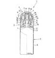
【図1】本発明の一実施例を示す一部切欠き側面図である。
【図2】同実施例の閉蓋状態の一部切欠き側面図である。
【図3】同実施例の斜視図である。
【符号の説明】
2…容器体,3…キャップ本体,4…蓋体,5…弾性部材,6…胴部,
7…口頚部,9…嵌合筒,10…頂板,11…ノズル,17…薄肉ヒンジ,
23…筒状部,24…帯状部,a…注出口,a1…注出用透孔,b…凹凸面,
c…凹凸面[0001]
BACKGROUND OF THE INVENTION
The present invention relates to a dropping container, and more particularly to a dropping container provided with a stored liquid so as to be able to be dropped and collected.
[0002]
[Prior art]
Examples of the dripping container to be used by dropping and storing the stored liquid little by little include, for example, eye drop containers, etc., and these include a container body in which the mouth and neck are raised and a nozzle is fitted to the tip of the mouth and neck. In general, there is known a cap composed of a cap that is detachably mounted by extending a top wall from an upper end edge of a peripheral wall in which a peripheral wall is fitted to the outer periphery of the neck and neck.
[0003]
In these containers, the caps are mounted by screwing on the outer periphery of the neck of the neck or by engaging over and protruding between the protrusions, and the caps are removed. In this way, the liquid is dropped.
[0004]
[Problems to be solved by the invention]
A conventional container with a cap screwed in is troublesome to attach and detach, such as having to be rotated many times. Also, it is troublesome to drop the liquid by holding the removed cap in your hand. There is also a risk of losing it somewhere.
[0005]
Further, in the case where the cap is configured to be fitted and locked by mutual engagement between the protrusions, the cap can be easily attached and detached as compared with the case of screwing. In order to pull out as if pulling, force is applied to the body, and there is a case where the liquid leaks from the spout as soon as the cap is removed. Similarly, the liquid must be dropped while holding the removed cap in the hand, and there is a risk of loss.
[0006]
The present invention has been made in consideration of such points, and it is easy to attach and detach the cap, there is no risk of losing the cap, and there is a problem that the liquid leaks accidentally when the cap is removed. We propose a dripping container that is extremely easy to use without fear of occurrence.
[0007]
[Means for Solving the Problems]
In order to solve the above problems, the dripping container of the present invention hangs the
[0008]
In addition, the container of the invention of
[0009]
According to a third aspect of the present invention, the outer peripheral surface of the
[0010]
DETAILED DESCRIPTION OF THE INVENTION
Hereinafter, embodiments of the present invention will be described with reference to the drawings.
The dropping
[0011]
The
[0012]
The
[0013]
In the illustrated example, the
[0014]
The lid 4 is also made of synthetic resin or the like, and is provided with a rear lower end pivotably connected to the rear portion of the
[0015]
The
[0016]
By providing this
[0017]
As described above, the tip of the belt-
[0018]
For the purpose of fixing the
[0019]
The case where the container constructed as described above is used will be described. First, when the engagement between the
[0020]
【The invention's effect】
As described above, since the container of the present invention has the above-described configuration, for example, the lid can be automatically opened and the liquid can be dropped by a simple operation of releasing the engagement of the front part of the lid. Thus, there is no inconvenience of holding the cap, and there is no inconvenience such as losing the cap.
[0021]
Further, since it can be performed without strongly gripping the body part when opening the lid, there is no possibility that the body part will be unnecessarily squeezed to cause liquid leakage.
Furthermore, if the container of the present invention is used as a container for eye drops, the presence of the cylindrical portion of the elastic member covers the nozzle that has been formed relatively hard heretofore, and can protect the eye when instilled. In addition, the elastic member has a simple structure, can be easily attached by fitting it into a conventional container of this type, and can exhibit the above functions, and has the advantage that it can be obtained without inconvenience in manufacturing. Yes.
[0022]
In addition, in the case where the end of the belt-like portion is extended to the inner surface of the lid in the opened state, the lid at the time of opening can be more securely fixed, and when the liquid is dropped Inconveniences such as the lid swaying can be further eliminated, and the liquid can be more easily dropped.
Furthermore, in the case where the outer peripheral surface of the nozzle is formed as an uneven surface, and the inner peripheral surface of the cylindrical portion is formed on the uneven surface closely fitting with the uneven surface, an elastic member simply fitted and fixed is used. Even if the lid is repeatedly opened and closed, inconveniences such as the elastic member coming off can be prevented as much as possible.
[Brief description of the drawings]
FIG. 1 is a partially cutaway side view showing an embodiment of the present invention.
FIG. 2 is a partially cutaway side view of the embodiment with the lid closed.
FIG. 3 is a perspective view of the same embodiment.
[Explanation of symbols]
2 ... container body, 3 ... cap body, 4 ... lid body, 5 ... elastic member, 6 ... trunk part,
7 ... neck and neck, 9 ... fitting tube, 10 ... top plate, 11 ... nozzle, 17 ... thin-walled hinge,
23 ... Cylindrical part, 24 ... Strip-like part, a ... Pouring port, a1 ... Pouring through hole, b ... Uneven surface,
c ... Uneven surface
Claims (3)
Translated fromJapanesePriority Applications (1)
| Application Number | Priority Date | Filing Date | Title |
|---|---|---|---|
| JP13467198AJP3740629B2 (en) | 1998-04-27 | 1998-04-27 | Dripping container |
Applications Claiming Priority (1)
| Application Number | Priority Date | Filing Date | Title |
|---|---|---|---|
| JP13467198AJP3740629B2 (en) | 1998-04-27 | 1998-04-27 | Dripping container |
Publications (2)
| Publication Number | Publication Date |
|---|---|
| JPH11310259A JPH11310259A (en) | 1999-11-09 |
| JP3740629B2true JP3740629B2 (en) | 2006-02-01 |
Family
ID=15133853
Family Applications (1)
| Application Number | Title | Priority Date | Filing Date |
|---|---|---|---|
| JP13467198AExpired - Fee RelatedJP3740629B2 (en) | 1998-04-27 | 1998-04-27 | Dripping container |
Country Status (1)
| Country | Link |
|---|---|
| JP (1) | JP3740629B2 (en) |
Families Citing this family (3)
| Publication number | Priority date | Publication date | Assignee | Title |
|---|---|---|---|---|
| JP2002362603A (en)* | 2001-06-06 | 2002-12-18 | Kitano Seisaku Kk | Eye drops container |
| JP5112755B2 (en)* | 2007-06-13 | 2013-01-09 | 伸晃化学株式会社 | Chemical container |
| JP7672910B2 (en)* | 2021-08-03 | 2025-05-08 | サーモス株式会社 | Cap unit and beverage container |
- 1998
- 1998-04-27JPJP13467198Apatent/JP3740629B2/ennot_activeExpired - Fee Related
Also Published As
| Publication number | Publication date |
|---|---|
| JPH11310259A (en) | 1999-11-09 |
Similar Documents
| Publication | Publication Date | Title |
|---|---|---|
| EP0404841A1 (en) | CLOSURE WITH A DONATION COMPONENT. | |
| JP4456306B2 (en) | cap | |
| JP3740629B2 (en) | Dripping container | |
| JP5590554B2 (en) | Application container | |
| JP3904788B2 (en) | Beverage container | |
| JP3916820B2 (en) | Synthetic resin tube container | |
| JP4018017B2 (en) | Liquid ejector | |
| JP2592498Y2 (en) | Container for mounting liquid ejection pump | |
| JP3828348B2 (en) | Inner stopper and fragrance container using the stopper | |
| JP3904753B2 (en) | Creamy product extraction container | |
| JP3720561B2 (en) | Synthetic resin pouring container | |
| JP4345914B2 (en) | Cap with lid | |
| JP3964103B2 (en) | Container with cap | |
| JP3771024B2 (en) | Eye drops container | |
| JPS6229406Y2 (en) | ||
| JP4392739B2 (en) | Liquid dispensing container | |
| JP3740628B2 (en) | Dripping container | |
| JP3579172B2 (en) | Liquid storage container | |
| JP4125852B2 (en) | Plastic container | |
| JP2601658Y2 (en) | Container lid with measuring cup | |
| JP4067741B2 (en) | Container with lid | |
| JPH0627604U (en) | cap | |
| JP3791749B2 (en) | Tube container | |
| JPH063862U (en) | Bottle stopper | |
| JP4010410B2 (en) | Container with stand |
Legal Events
| Date | Code | Title | Description |
|---|---|---|---|
| A977 | Report on retrieval | Free format text:JAPANESE INTERMEDIATE CODE: A971007 Effective date:20051017 | |
| TRDD | Decision of grant or rejection written | ||
| A01 | Written decision to grant a patent or to grant a registration (utility model) | Free format text:JAPANESE INTERMEDIATE CODE: A01 Effective date:20051025 | |
| A61 | First payment of annual fees (during grant procedure) | Free format text:JAPANESE INTERMEDIATE CODE: A61 Effective date:20051026 | |
| R150 | Certificate of patent or registration of utility model | Free format text:JAPANESE INTERMEDIATE CODE: R150 | |
| FPAY | Renewal fee payment (event date is renewal date of database) | Free format text:PAYMENT UNTIL: 20091118 Year of fee payment:4 | |
| FPAY | Renewal fee payment (event date is renewal date of database) | Free format text:PAYMENT UNTIL: 20101118 Year of fee payment:5 | |
| FPAY | Renewal fee payment (event date is renewal date of database) | Free format text:PAYMENT UNTIL: 20111118 Year of fee payment:6 | |
| FPAY | Renewal fee payment (event date is renewal date of database) | Free format text:PAYMENT UNTIL: 20121118 Year of fee payment:7 | |
| FPAY | Renewal fee payment (event date is renewal date of database) | Free format text:PAYMENT UNTIL: 20121118 Year of fee payment:7 | |
| FPAY | Renewal fee payment (event date is renewal date of database) | Free format text:PAYMENT UNTIL: 20131118 Year of fee payment:8 | |
| LAPS | Cancellation because of no payment of annual fees |