JP3739911B2 - Application tool - Google Patents
Application toolDownload PDFInfo
- Publication number
- JP3739911B2 JP3739911B2JP28906297AJP28906297AJP3739911B2JP 3739911 B2JP3739911 B2JP 3739911B2JP 28906297 AJP28906297 AJP 28906297AJP 28906297 AJP28906297 AJP 28906297AJP 3739911 B2JP3739911 B2JP 3739911B2
- Authority
- JP
- Japan
- Prior art keywords
- valve
- slit
- application
- wall
- container
- Prior art date
- Legal status (The legal status is an assumption and is not a legal conclusion. Google has not performed a legal analysis and makes no representation as to the accuracy of the status listed.)
- Expired - Fee Related
Links
- 230000002093peripheral effectEffects0.000claimsdescription11
- 239000011248coating agentSubstances0.000claimsdescription4
- 238000000576coating methodMethods0.000claimsdescription4
- 239000007788liquidSubstances0.000description20
- 239000000126substanceSubstances0.000description7
- 229920003002synthetic resinPolymers0.000description4
- 239000000057synthetic resinSubstances0.000description4
- 239000002537cosmeticSubstances0.000description3
- 230000000694effectsEffects0.000description3
- 230000015572biosynthetic processEffects0.000description2
- 239000008155medical solutionSubstances0.000description2
- 238000007789sealingMethods0.000description2
- 229920002379silicone rubberPolymers0.000description2
- 239000000806elastomerSubstances0.000description1
- 238000005507sprayingMethods0.000description1
- 238000010186stainingMethods0.000description1
Images
Landscapes
- Nozzles (AREA)
Description
Translated fromJapanese【0001】
【発明の属する技術分野】
本発明は、塗布用具、とくにスリットバルブを用いた塗布部材を容器口筒部に取着した薬液あるいは化粧液の塗布用具に関する。
【0002】
【発明が解決しようとする課題】
用液の塗布用具として、容器の口部に注出部材を取着し、容器の胴部を押圧して一定量の内容液を注出し、所要個所に噴射塗布するようにした塗布用具は従来より周知である。
しかしながら、従来の塗布用具では、容器胴部の押圧は手操作によるため、押圧量を加減して適量の内容液を注出することは困難であり、内容液が必要以上に多くなるという問題点があった。
また、少量の内容液を注出することができないという問題点があった。
【0003】
そのため、従来の塗布用具を毛髪用の液塗布具に用いた場合には、余分の内容液によって毛髪を汚したり、毛髪がべたついたりするという問題があった。
また、皮膚用薬液の塗布に用いる場合には、適量の薬液を少範囲の患部に塗布することはできないという問題があった。
【0004】
本発明は、上記の問題点を解決することを技術的課題とし、少量の内容液を限られた範囲に効率的に塗布することができる塗布用具を提供することを目的とする。
【0005】
【課題を解決するための手段】
本発明は、上記の技術的課題を達成するため、塗布用具として、容器の口筒部に塗布部材を取着した塗布用具であって、前記塗布部材が、バルブヘッドを露出するよう取り付けられたスリットバルブを具備しており、スリットバルブは、外側表面を球面状の凹面とし、中央部にスリットを形成したオリフィス形成壁とオリスィス形成壁の周縁に連設され、上部を放物面状の曲面としたバルブ周壁とからなるバルブヘッドを備えていることを特徴とする構成を採用する。
前記スリットバルブは、容器の口筒部に嵌着される中栓に保持筒を介して取り付けられる。
【0006】
【発明の実施の形態】
次に、本発明の実施形態について、図面を参照して説明する。
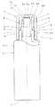
図1において、Aは容器、Bは容器に取着された塗布部材、Cはキャップである。
容器Aは、口筒部1と胴部2、底部3とからなり、合成樹脂によって合成されている。
口筒部1の外周には、ネジ4が刻設されており、上端には、突出環5が設けられ、その下方は、嵌合溝6となっている。
容器Aには、内容液として、毛髪用あるいは皮膚用薬液、化粧料などが収納される。
【0007】
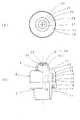
図2に示すように、塗布部材Bは、中栓7と保持筒8、両者によって挟持されたスリットバルブ9とからなっている。
中栓7は、上端にフランジ10を設けた嵌合筒11を有しており、嵌合筒11の中間部外周には、環状の突出板12が設けられ、該突出板12の周縁から嵌合筒13が垂設されており、嵌合筒13下端には内方に突出する膨出環14が設けられている。
前記保持筒8は、頂壁15と側筒壁16とを有しており、頂壁15には、スリットバルブ9を嵌挿する開口17が設けられ、側筒壁16の下端には、内方に突出する膨出環18が設けられている。
前記中栓7、保持筒8は、いずれも合成樹脂によって成型されている。
【0008】
スリットバルブ9は、側筒壁20とオリフィス形成壁21とからなっており、シリコンゴム、エラストマーまたは軟質の合成樹脂によって成型されている。
側筒壁20の中間部にはフランジ22が設けられており、側筒壁20の上部は放物面状のバルブ周壁23となっており、オリフィス形成壁21とともにバルブヘッド24を形成している。
オリフィス形成壁21の表面は、球面状の凹面25となっており、その周縁26は、バルブ周壁23に連続されている。
オリフィス形成壁21の中央部には、スリット27が切り込まれ、フラップ28が形成されており、フラップ28の開閉によってオリフィスが形成されるようになっている。
【0009】
図1に示すように、キャップCは、頂壁30と側筒壁31とからなっており、合成樹脂によって成型されている。
頂壁30下面中央には、突出部32が設けられ、その周辺は、閉蓋時にオリフィス形成壁21の周縁26を押圧する押圧面33となっており、押圧面33を囲んで下端面に膨出環34を設けた密封リング35が垂設されている。
側筒壁31の内周下方部には、容器Aの口筒部1に設けられたネジ4に螺合するネジ36が刻設されている。
【0010】
次に、塗布用具の形成について説明すると、スリットバルブ9の側筒壁20を中栓7の嵌合筒11内に嵌挿して、フランジ22を中栓7上端のフランジ10に接合させ、次いで、保持筒8を被せて、保持筒8の膨出環18を中栓7のフランジ10下面に係合させると、スリットバルブ9を組み込んだ塗布部材Bを得ることができる。
次いで、塗布部材Bの中栓7を容器Aの口筒部1内周に嵌挿させ、嵌合筒13の膨出環14を容器Aの口筒部1の突出環5の下面に嵌合させることによって、容器Aへの取付が行われ塗布用具が完成される。
【0011】
次に、本塗布用具の使用態様と作用効果について説明する。
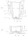
使用にあたって、キャップCを取り外し、スリットバルブ9を所要個所に押しあて、塗布用具を押しつけると、図3に示すようにスリットバルブ9のバルブ周壁23が膨らむよう変形されて、オリフィス形成壁21がその外側表面の曲率半径を小さくするよう湾曲して、スリット27が開かれ、オリフィスが形成される。 そして塗布用具の押しつけに応じて内圧が高められ、オリフィス形成壁21と塗布面との間に形成される空間内に、内容液が押出されることになる。
【0012】
塗布用具の押しつけを解くと、バルブ周壁23が復元し、スリット27が閉じるように作用する。その際、容器内は減圧状態となり、オリフィス形成壁21の凹面25内の内容液を引き戻すように作用し、塗布面aに付着した内容液を残して部分的に吸収される。
塗布用具を塗布面aから離すと、スリット27を通じて内圧が大気圧と同一になるまで空気が導入され、同一になるとスリット27が閉じられる。
塗布用具を塗布面から瞬時的に離すと、凹面25内の内容液の大部分が塗布面に残され、空気が導入されることになる。
したがって、極く少量の内容液を塗布することができ、多くともオリフィス形成壁21の凹面25の容積以上の内容液は吐出されないのである。
【0013】
使用後にキャップCを被嵌すると、キャップCの押圧面33によってオリフィス形成壁21の周縁26を押え、スリットバルブ9の妄動を阻止し、密封リング35によって気密が保たれるので液洩れが防止される。
【0014】
【発明の効果】
本発明は、上記のように構成されているから、次の効果を奏する。
塗布部材にスリットバルブを用いたことによって、少範囲の塗布面に適量の内容液を塗布することができるようになった。
そのため、毛髪用に薬液、化粧料を塗布する場合には、余分な内容液で毛髪を汚すことなく、また、皮膚面に薬液を塗布する場合にも、患部に適量の薬液を適用することができるようになった。
【図面の簡単な説明】
【図1】 本発明塗布用具の一部断面正面図である。
【図2】塗布部材を示す図で、(a)は平面図、(b)は一部断面正面図である。
【図3】塗布時のスリットバルブの説明図で、(a)は塗布用具の押しつけ時、(b)は離脱時の説明図である。
【符号の説明】
A 容器
B 塗布部材
C キャップ
1 口筒部
7 中栓
8 保持筒
9 スリットバルブ
20 側筒壁
21 オリフィス形成壁
23 バルブ周壁
24 バルブヘッド
25 凹面
26 周縁
27 スリット[0001]
BACKGROUND OF THE INVENTION
TECHNICAL FIELD The present invention relates to an application tool, and more particularly to a chemical liquid or cosmetic liquid application tool in which an application member using a slit valve is attached to a container mouth tube.
[0002]
[Problems to be solved by the invention]
Conventionally, as a liquid application tool, a dispensing member is attached to the mouth of a container, a predetermined amount of content liquid is poured by pressing the body of the container, and spray coating is applied to the required place. More well known.
However, in the conventional application tool, since the pressure on the container body is manually operated, it is difficult to dispense the appropriate amount of content liquid by adjusting the amount of pressure, and the content liquid becomes more than necessary. was there.
Moreover, there was a problem that a small amount of the content liquid could not be poured out.
[0003]
Therefore, when the conventional applicator is used for the liquid applicator for hair, there is a problem that the hair is soiled with extra content liquid or the hair becomes sticky.
Moreover, when using it for application | coating of the chemical | medical solution for skin, there existed a problem that an appropriate quantity of chemical | medical solutions could not be apply | coated to a small range of an affected part.
[0004]
This invention makes it a technical subject to solve said problem, and it aims at providing the applicator which can apply | coat a small amount of content liquids efficiently in the limited range.
[0005]
[Means for Solving the Problems]
In order to achieve the above technical problem, the present invention is an application tool in which an application member is attached to a mouth tube portion of a container as an application tool, and the application member is attached so as to expose the valve head. The slit valve has a spherical concave surface on the outer surface and isconnected to the periphery of the orifice-forming wall and the Orisis-forming wall with a slit in the center, with a parabolic curved surface at the top. A configuration characterized by comprising a valve head composed ofa valve peripheral wall is adopted.
The slit valve is attached to an inner plug fitted to the mouth tube portion of the container via a holding tube.
[0006]
DETAILED DESCRIPTION OF THE INVENTION
Next, embodiments of the present invention will be described with reference to the drawings.
In FIG. 1, A is a container, B is an application member attached to the container, and C is a cap.
The container A includes a
A screw 4 is engraved on the outer periphery of the
In the container A, hair or skin chemicals, cosmetics, and the like are stored as content liquids.
[0007]
As shown in FIG. 2, the application member B includes an
The
The
The
[0008]
The
A
The surface of the
A
[0009]
As shown in FIG. 1, the cap C includes a
A
A
[0010]
Next, the formation of the applicator will be described. The
Next, the
[0011]
Next, the usage mode and operation effects of the present application tool will be described.
In use, when the cap C is removed, the
[0012]
When the application tool is released, the valve
When the applicator is separated from the application surface a, air is introduced through the
When the application tool is instantaneously separated from the application surface, most of the content liquid in the
Therefore, a very small amount of content liquid can be applied, and at most, the content liquid exceeding the volume of the
[0013]
When the cap C is fitted after use, the
[0014]
【The invention's effect】
Since this invention is comprised as mentioned above, there exists the following effect.
By using a slit valve for the application member, an appropriate amount of content liquid can be applied to a small range of application surfaces.
Therefore, when applying chemicals and cosmetics for hair, it is possible to apply an appropriate amount of chemicals to the affected area without staining the hair with excess content liquids and also when applying chemicals to the skin surface. I can do it now.
[Brief description of the drawings]
FIG. 1 is a partially sectional front view of a coating tool of the present invention.
2A and 2B are views showing an application member, in which FIG. 2A is a plan view and FIG. 2B is a partial cross-sectional front view;
FIGS. 3A and 3B are explanatory views of a slit valve at the time of application, in which FIG. 3A is an explanatory view when the application tool is pressed, and FIG.
[Explanation of symbols]
A Container B Application
Claims (2)
Translated fromJapanese前記塗布部材が、バルブヘッドを露出するよう取り付けられたスリットバルブを具備しており、スリットバルブは、外側表面を球面状の凹面とし、中央部にスリットを形成したオリフィス形成壁とオリスィス形成壁の周縁に連設され、上部を放物面状の曲面としたバルブ周壁とからなるバルブヘッドを備えていることを特徴とする塗布用具。An application tool having an application member attached to the mouth tube portion of the container,
The coating member includes a slit valve attached to expose the valve head, and the slit valve has a spherical concave surface on the outer surface, and an orifice-forming wall and an Oris-forming wall formed with a slit in the center. An applicator characterized by comprising a valve head that is connected to the periphery and includesa valve peripheral wallhaving a parabolic curved surface at the top .
前記塗布部材が、容器の口筒部に嵌着される中栓と、該中栓に保持筒を介してバルブヘッドを露出するよう取り付けられたスリットバルブとを具備しており、スリットバルブは、外側表面を球面状の凹面とし、中央部にスリットを形成したオリフィス形成壁とオリスィス形成壁の周縁に連設され、上部を放物面状の曲面としたバルブ周壁とからなるバルブヘッドを備えていることを特徴とする塗布用具。An application tool having an application member attached to the mouth tube portion of the container,
The application member includes an inner plug fitted into the mouth tube portion of the container, and a slit valve attached to the inner plug so as to expose the valve head via the holding cylinder, A valve head comprising an orifice-forming wall having a spherical concave surface on the outer surface and a peripheral wall of an orifice-forming wall having a slit formed at the centerand a valve-shaped wallhaving a parabolic curved surface at the top. An application tool characterized in that the application tool.
Priority Applications (1)
| Application Number | Priority Date | Filing Date | Title |
|---|---|---|---|
| JP28906297AJP3739911B2 (en) | 1997-10-06 | 1997-10-06 | Application tool |
Applications Claiming Priority (1)
| Application Number | Priority Date | Filing Date | Title |
|---|---|---|---|
| JP28906297AJP3739911B2 (en) | 1997-10-06 | 1997-10-06 | Application tool |
Publications (2)
| Publication Number | Publication Date |
|---|---|
| JPH11104532A JPH11104532A (en) | 1999-04-20 |
| JP3739911B2true JP3739911B2 (en) | 2006-01-25 |
Family
ID=17738337
Family Applications (1)
| Application Number | Title | Priority Date | Filing Date |
|---|---|---|---|
| JP28906297AExpired - Fee RelatedJP3739911B2 (en) | 1997-10-06 | 1997-10-06 | Application tool |
Country Status (1)
| Country | Link |
|---|---|
| JP (1) | JP3739911B2 (en) |
- 1997
- 1997-10-06JPJP28906297Apatent/JP3739911B2/ennot_activeExpired - Fee Related
Also Published As
| Publication number | Publication date |
|---|---|
| JPH11104532A (en) | 1999-04-20 |
Similar Documents
| Publication | Publication Date | Title |
|---|---|---|
| US3961635A (en) | Hair treating liquid applicator | |
| US5154328A (en) | Unit for dispensing at least one fluid product, in particular a cosmetic or pharmaceutical product, having a pressure actuated, self-sealing, closure outlet | |
| US5388728A (en) | Unit for dispensing at least one fluid product, in particular a cosmetic or pharmaceutical product | |
| JP3095736B2 (en) | Assemblies for containing and dispensing liquid formulations | |
| AU748025B2 (en) | Container valve | |
| US5846011A (en) | Bottle with built-in telescoping applicator head and spout for applying fluid to a body | |
| US5860571A (en) | Dispensing bottle having two openings | |
| US6050274A (en) | Applicator | |
| RU2225817C2 (en) | Liquid container | |
| JP3771370B2 (en) | Container with applicator | |
| JP3739911B2 (en) | Application tool | |
| JP4282290B2 (en) | Liquid application container | |
| JP4565809B2 (en) | Liquid container with dispensing tool | |
| JPH11138086A (en) | Liquid application container | |
| JPH0451706Y2 (en) | ||
| JP4037145B2 (en) | Comb type container | |
| JP2002337911A (en) | Cap with slit valve | |
| JP4397605B2 (en) | Liquid container with dispensing tool | |
| WO1999007614A1 (en) | Container | |
| JP3657310B2 (en) | Discharge container | |
| JPH09142500A (en) | Tube container | |
| JPS589530Y2 (en) | Application type container with backflow prevention mechanism | |
| JPH0539092Y2 (en) | ||
| JPS6346027Y2 (en) | ||
| KR101946993B1 (en) | Cosmetic applicator head and cosmetic container having the same |
Legal Events
| Date | Code | Title | Description |
|---|---|---|---|
| A977 | Report on retrieval | Free format text:JAPANESE INTERMEDIATE CODE: A971007 Effective date:20050218 | |
| A131 | Notification of reasons for refusal | Free format text:JAPANESE INTERMEDIATE CODE: A131 Effective date:20050315 | |
| A521 | Written amendment | Free format text:JAPANESE INTERMEDIATE CODE: A523 Effective date:20050509 | |
| TRDD | Decision of grant or rejection written | ||
| A01 | Written decision to grant a patent or to grant a registration (utility model) | Free format text:JAPANESE INTERMEDIATE CODE: A01 Effective date:20051101 | |
| A61 | First payment of annual fees (during grant procedure) | Free format text:JAPANESE INTERMEDIATE CODE: A61 Effective date:20051104 | |
| R150 | Certificate of patent or registration of utility model | Free format text:JAPANESE INTERMEDIATE CODE: R150 | |
| FPAY | Renewal fee payment (event date is renewal date of database) | Free format text:PAYMENT UNTIL: 20091111 Year of fee payment:4 | |
| FPAY | Renewal fee payment (event date is renewal date of database) | Free format text:PAYMENT UNTIL: 20101111 Year of fee payment:5 | |
| FPAY | Renewal fee payment (event date is renewal date of database) | Free format text:PAYMENT UNTIL: 20111111 Year of fee payment:6 | |
| FPAY | Renewal fee payment (event date is renewal date of database) | Free format text:PAYMENT UNTIL: 20121111 Year of fee payment:7 | |
| FPAY | Renewal fee payment (event date is renewal date of database) | Free format text:PAYMENT UNTIL: 20131111 Year of fee payment:8 | |
| LAPS | Cancellation because of no payment of annual fees |