JP3737121B2 - Apparatus and method for pressure and temperature waveform analysis - Google Patents
Apparatus and method for pressure and temperature waveform analysisDownload PDFInfo
- Publication number
- JP3737121B2 JP3737121B2JP51987097AJP51987097AJP3737121B2JP 3737121 B2JP3737121 B2JP 3737121B2JP 51987097 AJP51987097 AJP 51987097AJP 51987097 AJP51987097 AJP 51987097AJP 3737121 B2JP3737121 B2JP 3737121B2
- Authority
- JP
- Japan
- Prior art keywords
- patient
- pressure
- signal
- thermistor
- monitoring device
- Prior art date
- Legal status (The legal status is an assumption and is not a legal conclusion. Google has not performed a legal analysis and makes no representation as to the accuracy of the status listed.)
- Expired - Fee Related
Links
- 238000004458analytical methodMethods0.000titleclaimsabstractdescription8
- 238000000034methodMethods0.000titledescription12
- 230000000241respiratory effectEffects0.000claimsdescription11
- 208000008784apneaDiseases0.000claimsdescription10
- 206010021079HypopnoeaDiseases0.000claimsdescription9
- 239000012530fluidSubstances0.000claimsdescription3
- 238000004891communicationMethods0.000claimsdescription2
- 238000012806monitoring deviceMethods0.000claims7
- 230000029058respiratory gaseous exchangeEffects0.000abstractdescription22
- 208000019116sleep diseaseDiseases0.000abstractdescription8
- 238000012544monitoring processMethods0.000abstractdescription6
- 208000020685sleep-wake diseaseDiseases0.000abstractdescription3
- 238000003745diagnosisMethods0.000abstractdescription2
- 239000003570airSubstances0.000description9
- 230000001771impaired effectEffects0.000description8
- 210000001331noseAnatomy0.000description8
- 201000002859sleep apneaDiseases0.000description8
- 208000001797obstructive sleep apneaDiseases0.000description7
- 208000023504respiratory system diseaseDiseases0.000description5
- 210000003928nasal cavityAnatomy0.000description4
- 230000008569processEffects0.000description4
- 208000004756Respiratory InsufficiencyDiseases0.000description3
- 206010038678Respiratory depressionDiseases0.000description3
- 230000002159abnormal effectEffects0.000description3
- 208000037265diseases, disorders, signs and symptomsDiseases0.000description3
- 208000035475disorderDiseases0.000description3
- 230000000694effectsEffects0.000description3
- 230000008901benefitEffects0.000description2
- 238000006243chemical reactionMethods0.000description2
- 238000010586diagramMethods0.000description2
- 230000000737periodic effectEffects0.000description2
- 230000010349pulsationEffects0.000description2
- 208000022925sleep disturbanceDiseases0.000description2
- 208000011580syndromic diseaseDiseases0.000description2
- 206010020591HypercapniaDiseases0.000description1
- 206010021143HypoxiaDiseases0.000description1
- 206010024264LethargyDiseases0.000description1
- 208000001705Mouth breathingDiseases0.000description1
- 208000031481Pathologic ConstrictionDiseases0.000description1
- 206010062519Poor quality sleepDiseases0.000description1
- 206010036790Productive coughDiseases0.000description1
- 206010038669Respiratory arrestDiseases0.000description1
- 241000287181Sturnus vulgarisSpecies0.000description1
- 239000000853adhesiveSubstances0.000description1
- 230000001070adhesive effectEffects0.000description1
- 238000004378air conditioningMethods0.000description1
- 239000012080ambient airSubstances0.000description1
- 230000003321amplificationEffects0.000description1
- 230000037007arousalEffects0.000description1
- QVGXLLKOCUKJST-UHFFFAOYSA-Natomic oxygenChemical compound[O]QVGXLLKOCUKJST-UHFFFAOYSA-N0.000description1
- 208000006218bradycardiaDiseases0.000description1
- 230000036471bradycardiaEffects0.000description1
- 230000006735deficitEffects0.000description1
- 238000001514detection methodMethods0.000description1
- 206010015037epilepsyDiseases0.000description1
- 238000001914filtrationMethods0.000description1
- 210000003128headAnatomy0.000description1
- 208000018875hypoxemiaDiseases0.000description1
- 230000003434inspiratory effectEffects0.000description1
- 230000003993interactionEffects0.000description1
- 238000007620mathematical functionMethods0.000description1
- 238000005259measurementMethods0.000description1
- 238000012986modificationMethods0.000description1
- 230000004048modificationEffects0.000description1
- 238000003199nucleic acid amplification methodMethods0.000description1
- 229910052760oxygenInorganic materials0.000description1
- 239000001301oxygenSubstances0.000description1
- 230000007310pathophysiologyEffects0.000description1
- 230000002085persistent effectEffects0.000description1
- 230000009467reductionEffects0.000description1
- 230000035945sensitivityEffects0.000description1
- 238000001228spectrumMethods0.000description1
- 210000003802sputumAnatomy0.000description1
- 208000024794sputumDiseases0.000description1
- 230000036262stenosisEffects0.000description1
- 208000037804stenosisDiseases0.000description1
- 230000000638stimulationEffects0.000description1
- 238000012546transferMethods0.000description1
Images


Classifications
- A—HUMAN NECESSITIES
- A61—MEDICAL OR VETERINARY SCIENCE; HYGIENE
- A61B—DIAGNOSIS; SURGERY; IDENTIFICATION
- A61B5/00—Measuring for diagnostic purposes; Identification of persons
- A61B5/08—Measuring devices for evaluating the respiratory organs
- A61B5/087—Measuring breath flow
- A61B5/0878—Measuring breath flow using temperature sensing means
Landscapes
- Health & Medical Sciences (AREA)
- Life Sciences & Earth Sciences (AREA)
- Medical Informatics (AREA)
- Molecular Biology (AREA)
- Pulmonology (AREA)
- Biophysics (AREA)
- Pathology (AREA)
- Engineering & Computer Science (AREA)
- Biomedical Technology (AREA)
- Heart & Thoracic Surgery (AREA)
- Physiology (AREA)
- Physics & Mathematics (AREA)
- Surgery (AREA)
- Animal Behavior & Ethology (AREA)
- General Health & Medical Sciences (AREA)
- Public Health (AREA)
- Veterinary Medicine (AREA)
- Measurement Of The Respiration, Hearing Ability, Form, And Blood Characteristics Of Living Organisms (AREA)
- Turbine Rotor Nozzle Sealing (AREA)
- Respiratory Apparatuses And Protective Means (AREA)
- Measuring And Recording Apparatus For Diagnosis (AREA)
- Measuring Fluid Pressure (AREA)
Abstract
Description
Translated fromJapanese本特許出願は、1995年11月17日付けで出願された、U.S.特許出願No.60/006,883の特典を請求するものである。
発明の背景
一般的には、本発明は睡眠障害の診断に関わり、より詳しくは睡眠中の患者の呼吸の監視に関するものである。ひとたび睡眠障害の原因が明らかにされれば、適当な治療を処方することができる。
睡眠に関わる問題は、種々の呼吸障害を包含する多数の原因の何れかに起因する可能性がある。例えば、閉塞性睡眠時無呼吸症候群(OSAS)は成人世代の1-5%程度が罹っている可能性のある、十分に認識された障害である。OSASは、過度の日中の嗜眠の最も一般的な原因の一つである。OSASは肥満した男性において最も頻繁に見られ、また睡眠障害クリニックに紹介される、唯一の、最も頻度の高い理由である。
OSASは、患者の上部気道の解剖学的または機能的な狭窄がある、あらゆる状態と関連し、また睡眠中に生ずる該上部気道の間欠的な妨害によって特徴付けられる。この妨害は、たゆまぬ呼吸努力にも拘らず、完全な空気流不在(無呼吸)状態から、空気流の低下したまたは低下しないかなりの妨害(呼吸低下および鼾)に及び呼吸妨害スペクトルをもたらす。この症候群の罹患状態は、低酸素血症、高炭酸症、徐拍および無呼吸、および睡眠からの覚醒に関連した睡眠妨害により発生する。
OSASの病理生理学は、完全には明らかにされていない。しかしながら、今や睡眠中の該上部気道の妨害は、部分的には呼気努力によって発生する負の管腔内圧が作用している間の、声門上部区域の圧潰性によるものである。かくして、睡眠中のヒトの上部気道はスターリングレジスター(Starling registor)として挙動し、該レジスターは、該空気流が作動(吸気)圧とは無関係に、一定値に制限されるという特徴によって定義される。次に、部分的または完全な気道の圧潰が、気道音の喪失と関連して発生する可能性があり、該気道音は睡眠開始の特徴であり、かつOSASにおいて大きくなる。主な睡眠無呼吸症は、空気調節、即ち適当な時点での呼吸サイクルに必要な、神経−筋肉刺激を、身体が自動的に発生できないことと関連している。穏健な(central)睡眠呼吸低下症は同様な原因をもち、またこの障害を減少するための電気的な刺激の利用と関連する作用は、持続している。
呼吸の検出は睡眠中に行われている、心臓における生理的監視である。対象が正常であることを立証すること、あるいは呼気中の休止、および異常な空気流が障害性の無呼吸、上部空気流抵抗症候群および重度の鼾等の症状をもつ患者に見られる覚醒の原因となっている、障害性のエピソードを同定することが必須である。呼吸監視の通常の標準的な形態は、鼻または口の近傍に配置して、温度変化を検出する(呼気中の高温空気、および吸気中のより低温の周囲空気)のためのサーミスタまたは熱伝対、温度感受性デバイスである。しかしながら、該サーミスタまたは熱伝対デバイスは、これらが殆ど「オールオアナッシングデバイス」であることから、一旦検出された空気流を正確に定量化する能力に欠けている。それにも拘らず、このようなデバイスが、温度変化を大雑把に定量化する試みにおいて、一般的に使用されている。直接空気流を監視するために、他のデバイスが利用されている(呼吸流量計)が、これらは全て、鼻または口を通して通過した空気の体積を直接的に捕獲し、かつ測定することに依っており、従って該空気を捕獲するためにマスクを必要とする。
より最近になって、(温度等の間接的なモニターとは逆に)真の流動シグナルから、その空気流シグナルのグラフを使用して、低い空気流(呼吸低下)または完全な呼吸停止(無呼吸)の存在以外に、空気流の減少を示さない高い気道抵抗をもたらす異常な上部気道能力の状態を示すことができることが、提案されている。以前に提案された技術は、鼻カニューレと高感度の圧力変換器との組み合わせを必要としている。酸素を放出するデバイス等とは対照的に、この方法を利用した場合、該カニューレチップとヒト外鼻腔との相互作用が、呼吸流量計ヘッドの形状を形成し、そのため鼻内部から外部に渡る圧力降下(鼻カニューレにより検出される)は、該空気流に比例する。このシグナルは、真のマスクに取り付けられ、較正された呼吸流量計からのシグナルに顕著に比例し、その結果睡眠中の呼吸を監視するための快適かつ高感度な方法を与える。しかしながら、このようなデバイスの使用においては、口からの呼吸を検出できず、また極めて小さな呼吸に対する感度が低いという2つの固有の制限がある。
従って、空気流の正確な測定並びに口の呼吸および極めて小さな呼吸を検出する能力をもたらす、より正確な方法が必要とされている。更に、比較的安価であって、使用が容易であり、また患者に対するあらゆる不快感を最小化する能力をもつデバイスを提供することが最も望ましい。
発明の概要
本発明は、従来技術の該諸欠点を克服して、患者の呼吸を正確に監視できるデバイスおよび方法を提供するものである。本発明のデバイスは、比較的安価であり、部分的に再利用可能であり、使用が容易であり、かつ監視中の患者にとっては比較的快適である。睡眠中の患者の呼吸パターンに関連する正確なデータがひとたび収集されれば、特定の呼吸障害が同定でき、あるいは該患者の睡眠に関わる問題の原因として解消し、かつ適当な治療に着手することができる。
本発明は、鼻カニューレを介して患者と連絡している高感度圧力変換器と、適当に配置されたサーミスタとを組み合わせたデバイスを提供する。該サーミスタは、2つの別々のセンサを取付けかつ配置することに対する不快感を緩和する、鼻の錐状突起に取り付けることによって、所定の位置に維持される。更に、この比較的高価で再利用可能なサーミスタは、比較的安価で使い捨て可能な該カニューレおよび鼻錐状突起から着脱可能である。
これら2つのデバイスの出力は、該患者の呼吸パターンを解析するように組み合わされる。結果として、該患者の呼吸は正常なものとして、穏健なまたは障害性の無呼吸のエピソード状態にあるものとして、あるいは穏健なまたは障害性の呼吸低下のエピソード状態にあるものとして特徴付けられる。
本発明のこれらのおよびその他の特徴並びに利点は、添付図面と共に記載される、本発明の原理を例示する以下の好ましい態様の説明から明らかとなろう。
【図面の簡単な説明】
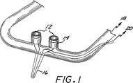
第1〜3図は、非−着脱式のサーミスタ構成をもつ、本発明の態様の斜視図である。
第4図は、鼻錐状突起に取り付けられた、着脱式のサーミスタを示す斜視図である。
第5図は、着脱式サーミスタエレメントを示す斜視図である。
第6図は、もう一つの着脱式サーミスタエレメントを示す斜視図である。
第7aおよび7b図は、着脱式のサーミスタ構成を使用した他の態様のデバイスの正面および側面図である。
第8図は、患者の鼻上の所定位置に配置された圧力検知デバイスを示す側面図である。
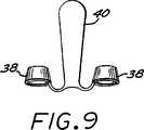
第9図は、第8図に示されたデバイスの正面図である。
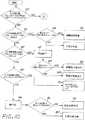
第10および11図は、圧力センサとサーミスタとの組み合わせからの出力を解釈するための一方法を示す流れ図である。
好ましい態様の詳細な説明
以下の態様は、本発明に従って、圧力検知装置と温度検知デバイスとを組み合わせることのできる方法の種々の例を与える。得られたデバイスは、容易に患者に取付けられ、かつ呼吸障害を迅速に診断するのに必要なデータを提供する。
第1図は鼻錐状突起と熱センサとの組み合わせを例示する。該鼻の錐状突起12は、患者の外鼻腔内に伸びており、また高感度圧力センサと流体接続18状態にある。サーミスタは、ほぼ各鼻の錐状突起と等しくなるように被覆14され、下方16に伸びて、該患者の口を覆っている。このサーミスタは電子検知装置と電気的に接続20されていて、温度にほぼ比例するシグナルを与える。
第2図は、もう一つの態様を示し、ここでサーミスタ22は該鼻の錐状突起の回りに巻付けられ、あるいはそこで螺旋状となっている。このサーミスタは、また該患者の口の上方を、下方16に伸びている。
第3図は、更に別の態様を示し、この態様においてサーミスタ24は、カニューレ内に配置され、該鼻の錐状突起から上方に伸び、かつ該患者の口上を、下方16に伸びている。
第4図は、サーミスタエレメント26が着脱式であり、またクリップ28によって所定の位置に保持されている一構成を示す。第5図は、一着脱式の構成を示し、該構成において該サーミスタはバンド30を含み、該バンドは該鼻の錐状突起上を滑動し、一方で第6図は、該サーミスタがコイル32を含む一態様を示し、該コイルは同様に該鼻の錐状突起上に取り付けられている。
第7aおよび7b図は、着脱式サーミスタ構成のもう一つの態様を示し、この態様において該鼻用のカニューレは、その前部表面上に延長部分34を含み、該表面はそこに形成された孔をもち、該孔を介して該サーミスタ36の下向きの部分16が通過している。これは、該デバイスを所定の位置に着脱可能に維持するように機能している。該サーミスタの該下向きの部分35は、該鼻の錐状突起12に沿って伸びている。
第8図は、該圧力センサの感度を高める構成を示す。各外鼻腔35内に配置された漏斗−状のインサート38が、該鼻の流入および流出中の圧力降下を発生する。該インサートは支持体40に取り付けられ、該支持体はテープ42または接着性の裏材により鼻37に支持されている。導管44は、18において、該外鼻腔内部と圧力検知デバイスとを流体接続状態にしている。
第9図は、このような態様を正面図として示す図である。このデバイスは、更に着脱式または非−着脱式に、サーミスタと接続されていてもよい。
動作に際して、該鼻のカニューレ/サーミスタの組み合わせが、患者に取り付けられ、かつ該圧力検知および温度検知デバイスと相互に接続される。患者が睡眠状態に入ると、その呼吸パターンが連続的に追跡される。これらデータの分析は、このような呼吸パターンが正常であるか、あるいは穏健な呼吸低下または障害性の呼吸低下の徴候であるかを明らかにする。着脱式構成においては、比較的安価で、かつ滅菌が困難なカニューレおよび鼻の錐状突起を廃棄し、一方で比較的高価なサーミスタを滅菌し、再利用する。
第10および11図は、本発明のデバイスの発生したデータを利用して、呼吸障害を診断する方法を例示するものである。
第10図に示したように、この監視シーケンスを開始する際には、先ず段階50において、該圧力センサが所定期間内に、例えば2分以内に呼吸を検出するか否かを決定する。そうでない場合には、該シーケンスは第11図につながり、単にサーミスタのみに頼ることになる。一呼吸が所定の期限内に検出された場合には、段階52においては、圧力振幅が第一の所定の限界、例えば、前の5分間等といった所定の期間中に検知された平均振幅の50%を越えるか否かについて、決定がなされる。該圧力波形の解析は、段階54にて行われ、該段階においてこのような解析は今や当分野で周知であり、実質的に米国特許第5,335,654号に記載のものと一致している。この特許を本発明の参考文献とする。一般的に、「制限流動」の形状は、実質的に正弦波形からのずれにより、曲線の平坦化、即ち該患者の吸気に対応する波形部分におけるプラトー部分の存在によって示される。流動制限事象56であることが示された場合においても、検出された呼吸振幅によって、該事象が呼吸低下であるということにはならない。出現する正常な波形は、正常な呼吸58を表す。
他方、該呼吸の振幅が、52において、該第一の限界未満であると決定された場合には、これは再度段階60で検査され、第二の振幅限界、例えば10%を越えるか否かが決定される。このような場合には、呼吸低下であることが示され62、かつその波形は64において再度チェックされ、制限流動形状が障害性呼吸低下である部分において、障害呼吸低下と穏健呼吸低下との間の識別を行う。段階60において、該呼吸振幅が該第二の振幅限界以下であると決定された場合には、該サーミスタの振幅を、予め選択された限界、例えば、前の5分間等の所定の期間において検知された平均の振幅の10%と比較する。このような限界を越えた場合には、未だ特定されていない呼吸低下であることが示される72。該サーミスタの振幅が該予め選択された限界に達しない場合には、無呼吸であることが示され74、また圧力波形は段階76で、心臓の拍動、即ち心拍数の範囲内の頻度をもつ、規則性ある低振幅の脈動であるかについて検査する。これらの脈動は、これらの振幅を増幅するように、適当に濾波し、かつ変換した後に、該流動シグナルから検出することができる。このシグナル変換関数(これは優先的に、平均値近傍のシグナルの振幅を増大する)は、非線形の数学的関数(例えば、平方根)およびルック−アップ表とを含むことができるが、これらに限定されない。従って、これらの周期的な揺らぎは、心臓拍動サイクルの頻度(例えば、40-120/分)と同様な頻度で揺らぎを同定する周期増幅技術および/または分散をもつ変換されたシグナル中に検出される。このような振動が存在しない場合には、障害性の無呼吸であることが示され78、他方このような振動が同定された場合には、穏健な無呼吸であることが示される80。
段階50にもどると、該所定の期間内に該圧力センサにより如何なる呼吸も検出されないことが、初期に決定された場合には、該サーミスタの出力が、段階82においてチェックされ、どのようにして例えば2分間の所定の期間内にどれほどの呼吸が検出されるかを決定する。サーミスタ活性が何等記録されなかった場合には、連絡の途絶を示し84、警告音を発することもできる。82において、幾らかのサーミスタ活性が記録される場合には、その振幅は段階86でチェックされる。所定の限界よりも大きな振幅は、口を介するとはいえ、正常な呼吸88を表す。このような限界を達成できないと、段階90において、大幅に低い限界と該振幅とが比較される。このような限界を越える振幅は、92において、未だ特定されていない型の呼吸低下を表し、一方でこのような限界よりも低い振幅は、未だ特定されていない型の無呼吸を表す。圧力シグナルがないことは、呼吸低下または無呼吸の障害性と穏健性との間の識別努力における、波形の分析を妨害する。
要するに、高度に正確な圧力シグナルは、まず呼吸障害を診断しようとの努力に依っている。強力な圧力シグナルのない状況では、分析の目的で、より不正確な温度シグナルが再分類される。該2つのシグナルの組み合わせは、排他的に何れかのシグナルに基づいて得ることのできるよりも、より一層正確な、患者の呼吸性能の指標を与える。
このような監視を、任意の所定の期間に渡って継続する。その後、呼吸出現の型および異常な呼吸のかかる出現の頻度を解析して、呼吸障害の存在を示し、結果として任意の睡眠障害に関する洞察を与えるか否かに関する見解を与える。
以上、本発明の特定の型を例示し、かつ記載してきたが、当業者には、本発明の精神並びに範囲を逸脱することなく、種々の改良をなし得ることも明らかであろう。より詳細には、異なる種々の温度センサを使用することができ、またこのようなセンサは、種々の方法の何れかで、鼻カニューレおよび錐状突起と組み合わせて、適当な配置を保証し、かつ場合により着脱性を与えることができる。圧力センサと温度センサとの組み合わせにより発生するデータの分析においては、上記の好ましい態様において記載したものとは、異なる限界を設定することができる。従って、本発明の範囲を、添付した請求の範囲以外によって限定するつもりはない。This patent application claims the benefit of US Patent Application No. 60 / 006,883, filed November 17, 1995.
BACKGROUND OF THE INVENTION Generally, the present invention relates to the diagnosis of sleep disorders, and more particularly to monitoring patient breathing during sleep. Once the cause of sleep disturbance is identified, appropriate treatment can be prescribed.
Sleep problems can result from any of a number of causes, including various respiratory disorders. For example, obstructive sleep apnea syndrome (OSAS) is a well-recognized disorder that can affect as much as 1-5% of the adult generation. OSAS is one of the most common causes of excessive daytime lethargy. OSAS is the most frequent reason seen most often in obese men and is referred to sleep disorder clinics.
OSAS is associated with any condition where there is an anatomical or functional stenosis of the patient's upper airway and is characterized by intermittent obstruction of the upper airway that occurs during sleep. This disturbance results in substantial disturbances (hypopnea and sputum) with reduced or unreduced airflow, from a complete absence of airflow (apnea), despite persistent breathing effort, and a respiratory disturbance spectrum. The morbidity of this syndrome arises from sleep disturbances associated with hypoxemia, hypercapnia, bradycardia and apnea, and arousal from sleep.
The pathophysiology of OSAS has not been fully elucidated. However, the obstruction of the upper airway during sleep is now due, in part, to the collapse of the upper glottic area during the negative intraluminal pressure generated by expiratory effort. Thus, the human upper airway during sleep behaves as a Starling registor, which is defined by the feature that the air flow is limited to a constant value, independent of the working (inspiratory) pressure . Second, partial or complete airway collapse may occur in association with the loss of airway sound, which is a feature of sleep onset and increases in OSAS. The main sleep apnea is associated with the inability of the body to automatically generate the nerve-muscle stimulation necessary for air conditioning, that is, the respiratory cycle at the appropriate time. Central sleep hypopnea has a similar cause and the effects associated with the use of electrical stimuli to reduce this disorder persist.
Respiration detection is a physiological monitoring in the heart that occurs during sleep. Causes of wakefulness seen in patients with evidence that the subject is normal or in exhalation pauses, and abnormal airflow, such as impaired apnea, upper airflow resistance syndrome and severe epilepsy It is essential to identify the impaired episodes. The usual standard form of respiratory monitoring is placed near the nose or mouth to detect temperature changes (hot air during exhalation and cooler ambient air during inspiration) or a thermistor or heat transfer. Vs. temperature sensitive devices. However, the thermistor or thermocouple device lacks the ability to accurately quantify the air flow once detected because they are mostly “all-or-nothing devices”. Nevertheless, such devices are commonly used in an attempt to roughly quantify temperature changes. Other devices have been utilized to directly monitor air flow (respiratory flow meters), all of which rely on directly capturing and measuring the volume of air that has passed through the nose or mouth. And therefore requires a mask to capture the air.
More recently, from a true flow signal (as opposed to an indirect monitor such as temperature), use a graph of its air flow signal to reduce low air flow (respiratory depression) or complete respiratory arrest (no In addition to the presence of (breathing), it has been proposed that abnormal upper airway capacity conditions can be shown that result in high airway resistance that does not show a reduction in airflow. Previously proposed techniques require a combination of a nasal cannula and a sensitive pressure transducer. In contrast to devices that release oxygen, etc., when this method is used, the interaction between the cannula tip and the human external nasal cavity forms the shape of the respiratory flow meter head, so that the pressure across the nose from the outside The descent (detected by the nasal cannula) is proportional to the air flow. This signal is attached to a true mask and is significantly proportional to the signal from a calibrated respiratory flow meter, thus providing a comfortable and sensitive way to monitor breathing during sleep. However, the use of such a device has two inherent limitations: it cannot detect breathing from the mouth and is insensitive to very small breaths.
Therefore, there is a need for a more accurate method that provides an accurate measurement of airflow and the ability to detect mouth breathing and extremely small breaths. Furthermore, it would be most desirable to provide a device that is relatively inexpensive, easy to use, and capable of minimizing any discomfort to the patient.
SUMMARY OF THE INVENTION The present invention overcomes the disadvantages of the prior art and provides a device and method that can accurately monitor patient breathing. The device of the present invention is relatively inexpensive, partially reusable, easy to use, and relatively comfortable for the patient being monitored. Once accurate data related to the patient's breathing pattern during sleep is collected, specific breathing disorders can be identified or resolved as the cause of the patient's sleep problems and appropriate treatment initiated Can do.
The present invention provides a device that combines a sensitive pressure transducer in communication with a patient via a nasal cannula and a suitably positioned thermistor. The thermistor is maintained in place by attaching it to the nasal cone, which alleviates the discomfort associated with attaching and placing two separate sensors. Furthermore, the relatively expensive and reusable thermistor is removable from the relatively inexpensive and disposable cannula and nasal cone.
The outputs of these two devices are combined to analyze the patient's breathing pattern. As a result, the patient's breathing is characterized as normal, as being in a moderate or impaired apnea episode state, or as being in a moderate or impaired hypopnea episode state.
These and other features and advantages of the present invention will become apparent from the following description of the preferred embodiments, illustrating the principles of the invention, described in conjunction with the accompanying drawings.
[Brief description of the drawings]
1-3 are perspective views of embodiments of the present invention having a non-detachable thermistor configuration.
FIG. 4 is a perspective view showing a detachable thermistor attached to a nasal cone projection.
FIG. 5 is a perspective view showing a detachable thermistor element.
FIG. 6 is a perspective view showing another detachable thermistor element.
Figures 7a and 7b are front and side views of another embodiment of the device using a detachable thermistor configuration.
FIG. 8 is a side view showing the pressure sensing device disposed at a predetermined position on the patient's nose.
FIG. 9 is a front view of the device shown in FIG.
FIGS. 10 and 11 are flow diagrams illustrating one method for interpreting the output from the combination of the pressure sensor and the thermistor.
Detailed Description of Preferred Embodiments The following embodiments provide various examples of how a pressure sensing device and a temperature sensing device can be combined in accordance with the present invention. The resulting device is easily attached to the patient and provides the data necessary to quickly diagnose a respiratory disorder.
FIG. 1 illustrates a combination of a nose cone process and a thermal sensor. The
FIG. 2 shows another embodiment, in which the thermistor 22 is wrapped around or spiraled around the nasal cone. The thermistor also extends down 16 above the patient's mouth.
FIG. 3 shows yet another embodiment, in which the thermistor 24 is disposed within the cannula and extends upwardly from the nasal conical process and extends downwardly 16 above the patient's mouth.
FIG. 4 shows a configuration in which the thermistor element 26 is detachable and is held in place by a
FIGS. 7a and 7b show another embodiment of a removable thermistor configuration, in which the nasal cannula includes an
FIG. 8 shows a configuration for increasing the sensitivity of the pressure sensor. A funnel-shaped
FIG. 9 is a diagram showing such a mode as a front view. This device may be further connected to the thermistor in a detachable or non-detachable manner.
In operation, the nasal cannula / thermistor combination is attached to a patient and interconnected with the pressure and temperature sensing device. As the patient enters sleep, their breathing pattern is continuously tracked. Analysis of these data reveals whether such a breathing pattern is normal or is a sign of moderate or impaired hypopnea. In a detachable configuration, the cannula and nasal cones that are relatively inexpensive and difficult to sterilize are discarded, while the relatively expensive thermistor is sterilized and reused.
FIGS. 10 and 11 illustrate a method of diagnosing a respiratory disorder using data generated by the device of the present invention.
As shown in FIG. 10, when starting this monitoring sequence, first, at
On the other hand, if the respiration amplitude is determined to be below the first limit at 52, it is again checked at
Returning to step 50, if it is initially determined that no respiration is detected by the pressure sensor within the predetermined time period, the thermistor output is checked in
In short, a highly accurate pressure signal relies first on an effort to diagnose a respiratory disorder. In the absence of a strong pressure signal, a more inaccurate temperature signal is reclassified for analytical purposes. The combination of the two signals gives a more accurate indication of the patient's respiratory performance than can be obtained exclusively based on either signal.
Such monitoring is continued for any predetermined period. The type of respiratory appearance and the frequency of such abnormal breathing occurrences are then analyzed to indicate the presence of a respiratory disorder and, as a result, give an insight about whether to give insight into any sleep disorder.
While specific forms of the invention have been illustrated and described, it will be apparent to those skilled in the art that various modifications can be made without departing from the spirit and scope of the invention. More specifically, a variety of different temperature sensors can be used, and such sensors can be combined with the nasal cannula and conical process in any of a variety of ways to ensure proper placement, and In some cases, detachability can be provided. In the analysis of the data generated by the combination of the pressure sensor and the temperature sensor, a limit different from that described in the above preferred embodiment can be set. Accordingly, it is not intended that the scope of the invention be limited except by the appended claims.
Claims (8)
Translated fromJapanese該患者の鼻内部および該患者の口近傍の温度を表すシグナルを発生するように動作する温度センサと、
該圧力シグナルと該温度シグナルとを同時に評価して、呼吸低下および無呼吸に関する、該患者の呼吸パターンの解析を簡略化する、シグナル処理器と、を含む、呼吸監視デバイス。A pressure transducer, wherein the transducer is in fluid communication with the patient's nose and operates to generate a signal representative of air pressure therein;
A temperature sensor operative to generate a signal representative of the temperature within the patient's nose and near the patient's mouth;
And a signal processor that simultaneously evaluates the pressure signal and the temperature signal to simplify analysis of the patient's respiratory pattern for hypopnea and apnea.
Applications Claiming Priority (3)
| Application Number | Priority Date | Filing Date | Title |
|---|---|---|---|
| US688395P | 1995-11-17 | 1995-11-17 | |
| US60/006,883 | 1995-11-17 | ||
| PCT/US1996/018619WO1997018752A1 (en) | 1995-11-17 | 1996-11-15 | Apparatus and method for pressure and temperature waveform analysis |
Publications (2)
| Publication Number | Publication Date |
|---|---|
| JP2000500379A JP2000500379A (en) | 2000-01-18 |
| JP3737121B2true JP3737121B2 (en) | 2006-01-18 |
Family
ID=21723093
Family Applications (1)
| Application Number | Title | Priority Date | Filing Date |
|---|---|---|---|
| JP51987097AExpired - Fee RelatedJP3737121B2 (en) | 1995-11-17 | 1996-11-15 | Apparatus and method for pressure and temperature waveform analysis |
Country Status (10)
| Country | Link |
|---|---|
| US (1) | US6165133A (en) |
| EP (1) | EP0955881B1 (en) |
| JP (1) | JP3737121B2 (en) |
| AT (1) | ATE201315T1 (en) |
| AU (1) | AU722212B2 (en) |
| CA (1) | CA2237985C (en) |
| DE (1) | DE69613009T2 (en) |
| DK (1) | DK0955881T3 (en) |
| ES (1) | ES2157469T3 (en) |
| WO (1) | WO1997018752A1 (en) |
Cited By (1)
| Publication number | Priority date | Publication date | Assignee | Title |
|---|---|---|---|---|
| JP2014008160A (en)* | 2012-06-28 | 2014-01-20 | Fukuda Denshi Co Ltd | Biological information collection device |
Families Citing this family (67)
| Publication number | Priority date | Publication date | Assignee | Title |
|---|---|---|---|---|
| US6675797B1 (en) | 1993-11-05 | 2004-01-13 | Resmed Limited | Determination of patency of the airway |
| AUPO247496A0 (en) | 1996-09-23 | 1996-10-17 | Resmed Limited | Assisted ventilation to match patient respiratory need |
| US6076520A (en)* | 1997-05-12 | 2000-06-20 | Cooper; Emily L. | Device for nasal therapeutic inhalation |
| AUPP026997A0 (en) | 1997-11-07 | 1997-12-04 | Resmed Limited | Administration of cpap treatment pressure in presence of apnea |
| IL122875A0 (en)* | 1998-01-08 | 1998-08-16 | S L P Ltd | An integrated sleep apnea screening system |
| US6017315A (en)* | 1998-02-25 | 2000-01-25 | Respironics, Inc. | Patient monitor and method of using same |
| US20050121033A1 (en)* | 1998-02-25 | 2005-06-09 | Ric Investments, Llc. | Respiratory monitoring during gas delivery |
| US6544192B2 (en) | 1998-02-25 | 2003-04-08 | Respironics, Inc. | Patient monitor and method of using same |
| US6398727B1 (en)* | 1998-12-23 | 2002-06-04 | Baxter International Inc. | Method and apparatus for providing patient care |
| US6679265B2 (en)* | 2001-10-25 | 2004-01-20 | Worldwide Medical Technologies | Nasal cannula |
| US7052470B2 (en)* | 2002-02-11 | 2006-05-30 | Gannon Mark D | Breathing detection/confirmation device |
| DE10248590B4 (en)* | 2002-10-17 | 2016-10-27 | Resmed R&D Germany Gmbh | Method and device for carrying out a signal-processing observation of a measurement signal associated with the respiratory activity of a person |
| US8020555B2 (en)* | 2003-06-18 | 2011-09-20 | New York University | System and method for improved treatment of sleeping disorders using therapeutic positive airway pressure |
| US7066180B2 (en)* | 2003-07-09 | 2006-06-27 | Airmatrix Technologies, Inc. | Method and system for measuring airflow of nares |
| US7118536B2 (en)* | 2003-07-25 | 2006-10-10 | Ric Investments, Llc. | Apnea/hypopnea detection system and method |
| US6988994B2 (en)* | 2003-08-14 | 2006-01-24 | New York University | Positive airway pressure system and method for treatment of sleeping disorder in patient |
| WO2005034750A1 (en)* | 2003-10-07 | 2005-04-21 | Olympus Corporation | Sleep aspiration state measurement device |
| JP4751338B2 (en)* | 2003-12-30 | 2011-08-17 | ユニバーシティ オブ フロリダ リサーチファウンデーション インコーポレイティッド | New and specially configured nasal pulse oximeter |
| US7276031B2 (en)* | 2004-05-12 | 2007-10-02 | New York University | System and method for classifying patient's breathing using artificial neural network |
| US7213594B2 (en)* | 2004-05-20 | 2007-05-08 | Acoba, L.L.C. | Method and system to determine nasal resistance to airflow |
| US20050268912A1 (en)* | 2004-06-04 | 2005-12-08 | Norman Robert G | System and method for automated titration of continuous positive airway pressure |
| US7037272B2 (en)* | 2004-07-26 | 2006-05-02 | Ohlan Silpachai | Infant respiratory monitoring system |
| US8061357B2 (en) | 2004-12-08 | 2011-11-22 | Ventus Medical, Inc. | Adhesive nasal respiratory devices |
| EP1824544B1 (en) | 2004-12-08 | 2013-06-05 | Ventus Medical, Inc. | Respiratory devices and methods of use |
| US10610228B2 (en) | 2004-12-08 | 2020-04-07 | Theravent, Inc. | Passive nasal peep devices |
| US9833354B2 (en) | 2004-12-08 | 2017-12-05 | Theravent, Inc. | Nasal respiratory devices |
| JP2006198093A (en)* | 2005-01-19 | 2006-08-03 | Izumi Products Co | Rotary electric shaver |
| JP2006212271A (en)* | 2005-02-04 | 2006-08-17 | Ngk Spark Plug Co Ltd | Respiration sensor, using method of respiration sensor and respiration state-monitoring device |
| JPWO2006095687A1 (en)* | 2005-03-09 | 2008-08-14 | 日本特殊陶業株式会社 | Breathing sensor, method of using the breathing sensor, and respiratory condition monitoring device |
| US8287460B2 (en)* | 2005-10-04 | 2012-10-16 | Ric Investments, Llc | Disordered breathing monitoring device and method of using same including a study status indicator |
| CA2653139C (en)* | 2006-05-23 | 2016-01-05 | Ventus Medical, Inc. | Nasal respiratory devices |
| EP2032213A4 (en) | 2006-06-07 | 2014-02-19 | Theravent Inc | DEVICES FOR THE NOSE |
| US20090145441A1 (en)* | 2007-12-06 | 2009-06-11 | Rajiv Doshi | Delayed resistance nasal devices and methods of use |
| CN101489630B (en) | 2006-06-07 | 2013-10-23 | 温吐斯医学公司 | Layered nasal devices |
| WO2008012625A2 (en)* | 2006-07-20 | 2008-01-31 | Cnr Consiglio Nazionale Delle Ricerche | Apparatus for controlled and automatic medical gas dispensing |
| WO2008061252A2 (en) | 2006-11-16 | 2008-05-22 | Ventus Medical, Inc. | Nasal devices applicators |
| CA2676119C (en) | 2007-01-29 | 2021-01-19 | Simon Fraser University | Transvascular nerve stimulation apparatus and methods |
| TW200836781A (en)* | 2007-03-07 | 2008-09-16 | Ventus Medical Inc | Nasal devices |
| US8020700B2 (en) | 2007-12-05 | 2011-09-20 | Ventus Medical, Inc. | Packaging and dispensing nasal devices |
| US8475369B2 (en)* | 2008-04-30 | 2013-07-02 | Ambu A/S | Integrated pressure and temperature cannula |
| WO2009149336A2 (en)* | 2008-06-06 | 2009-12-10 | Salter Labs | Adaptive temperature sensor for breath monitoring device |
| US20100168600A1 (en)* | 2008-06-06 | 2010-07-01 | Salter Labs | Support structure for airflow temperature sensor and the method of using the same |
| US20090306529A1 (en)* | 2008-06-06 | 2009-12-10 | Salter Labs | Adaptive temperature sensor for breath monitoring device |
| US20090306528A1 (en)* | 2008-06-06 | 2009-12-10 | Salter Labs | Adaptive temperature sensor for breath monitoring device |
| WO2010097718A1 (en) | 2009-02-25 | 2010-09-02 | Koninklijke Philips Electronics, N.V. | Automatic pressure titration |
| US8911380B1 (en) | 2009-04-17 | 2014-12-16 | Linshom, L.P. | Respiration monitoring system and method |
| WO2010120891A2 (en)* | 2009-04-17 | 2010-10-21 | Linshom L.P. | System and method for monitoring breathing |
| US8985106B2 (en)* | 2009-06-05 | 2015-03-24 | Resmed Limited | Methods and devices for the detection of hypopnoea |
| EP2440276B1 (en)* | 2009-06-09 | 2016-08-31 | Koninklijke Philips N.V. | Interface appliance carrying one or more sensors detecting parameters related to a flow of fluid delivered through the appliance |
| US8875711B2 (en) | 2010-05-27 | 2014-11-04 | Theravent, Inc. | Layered nasal respiratory devices |
| US20120150058A1 (en)* | 2010-12-09 | 2012-06-14 | Marc Zubrow | System and method for monitoring a patient for a respiratory arrest/death event |
| US20120226182A1 (en)* | 2011-03-04 | 2012-09-06 | Braebon Medical Corporation | Disposable thermal sensor for use with a cannula |
| US9789273B2 (en) | 2011-05-13 | 2017-10-17 | Koninklijke Philips N.V. | Sensor and valve integrated into a patient interface |
| EP2863987B1 (en) | 2012-06-21 | 2023-08-02 | Lungpacer Medical Inc. | Transvascular diaphragm pacing systems |
| JP6137823B2 (en)* | 2012-09-04 | 2017-05-31 | 日本光電工業株式会社 | Airway adapter, biological information acquisition system, and oxygen mask |
| US10112022B2 (en) | 2014-09-18 | 2018-10-30 | Devilbiss Healthcare Llc | Method for detecting an inspiratory flow limitation during sleep-disordered breathing |
| US11298074B2 (en) | 2015-12-08 | 2022-04-12 | Fisher & Paykel Healthcare Limited | Flow-based sleep stage determination |
| CN110325110B (en) | 2016-11-10 | 2022-08-09 | 纽约州立大学研究基金会 | Systems, methods, and biomarkers for airway obstruction |
| JP2018201724A (en) | 2017-05-31 | 2018-12-27 | 日本光電工業株式会社 | Respiratory pressure sensor |
| JP6952500B2 (en) | 2017-05-31 | 2021-10-20 | 日本光電工業株式会社 | Bio-information processing device |
| CN111163834A (en) | 2017-06-30 | 2020-05-15 | 隆佩瑟尔医疗公司 | Device for preventing, reducing and/or treating cognitive impairment |
| US10195429B1 (en) | 2017-08-02 | 2019-02-05 | Lungpacer Medical Inc. | Systems and methods for intravascular catheter positioning and/or nerve stimulation |
| WO2020232333A1 (en) | 2019-05-16 | 2020-11-19 | Lungpacer Medical Inc. | Systems and methods for sensing and stimulation |
| WO2020252037A1 (en) | 2019-06-12 | 2020-12-17 | Lungpacer Medical Inc. | Circuitry for medical stimulation systems |
| CN111803030A (en)* | 2020-06-25 | 2020-10-23 | 北京大众益康科技有限公司 | Sleep breathing result display system and method |
| WO2022047387A1 (en)* | 2020-08-31 | 2022-03-03 | Resmed Corp. | Systems and methods for determining a mask recommendation |
| WO2023107401A1 (en)* | 2021-12-06 | 2023-06-15 | Vyaire Medical, Inc. | Oxygenation cannula with flexible measurement circuit |
Family Cites Families (11)
| Publication number | Priority date | Publication date | Assignee | Title |
|---|---|---|---|---|
| US4648407A (en)* | 1985-07-08 | 1987-03-10 | Respitrace Corporation | Method for detecting and differentiating central and obstructive apneas in newborns |
| US4803997A (en)* | 1986-07-14 | 1989-02-14 | Edentec Corporation | Medical monitor |
| US5069222A (en)* | 1990-08-31 | 1991-12-03 | Mcdonald Jr Lewis D | Respiration sensor set |
| US5251636A (en)* | 1991-03-05 | 1993-10-12 | Case Western Reserve University | Multiple thin film sensor system |
| US5190048A (en)* | 1991-09-17 | 1993-03-02 | Healthdyne, Inc. | Thermistor airflow sensor assembly |
| US5335654A (en) | 1992-05-07 | 1994-08-09 | New York University | Method and apparatus for continuous adjustment of positive airway pressure for treating obstructive sleep apnea |
| US5490502A (en)* | 1992-05-07 | 1996-02-13 | New York University | Method and apparatus for optimizing the continuous positive airway pressure for treating obstructive sleep apnea |
| US5513646A (en)* | 1992-11-09 | 1996-05-07 | I Am Fine, Inc. | Personal security monitoring system and method |
| US5311875A (en)* | 1992-11-17 | 1994-05-17 | Peter Stasz | Breath sensing apparatus |
| US5546952A (en)* | 1994-09-21 | 1996-08-20 | Medtronic, Inc. | Method and apparatus for detection of a respiratory waveform |
| US5540733A (en)* | 1994-09-21 | 1996-07-30 | Medtronic, Inc. | Method and apparatus for detecting and treating obstructive sleep apnea |
- 1996
- 1996-11-15CACA002237985Apatent/CA2237985C/ennot_activeExpired - Lifetime
- 1996-11-15EPEP96940556Apatent/EP0955881B1/ennot_activeExpired - Lifetime
- 1996-11-15DKDK96940556Tpatent/DK0955881T3/enactive
- 1996-11-15JPJP51987097Apatent/JP3737121B2/ennot_activeExpired - Fee Related
- 1996-11-15DEDE69613009Tpatent/DE69613009T2/ennot_activeExpired - Lifetime
- 1996-11-15ATAT96940556Tpatent/ATE201315T1/enactive
- 1996-11-15USUS09/068,799patent/US6165133A/ennot_activeExpired - Lifetime
- 1996-11-15WOPCT/US1996/018619patent/WO1997018752A1/enactiveIP Right Grant
- 1996-11-15ESES96940556Tpatent/ES2157469T3/ennot_activeExpired - Lifetime
- 1996-11-15AUAU10211/97Apatent/AU722212B2/ennot_activeExpired
Cited By (1)
| Publication number | Priority date | Publication date | Assignee | Title |
|---|---|---|---|---|
| JP2014008160A (en)* | 2012-06-28 | 2014-01-20 | Fukuda Denshi Co Ltd | Biological information collection device |
Also Published As
| Publication number | Publication date |
|---|---|
| EP0955881A1 (en) | 1999-11-17 |
| DE69613009T2 (en) | 2001-11-15 |
| ATE201315T1 (en) | 2001-06-15 |
| EP0955881B1 (en) | 2001-05-23 |
| CA2237985A1 (en) | 1997-05-29 |
| DE69613009D1 (en) | 2001-06-28 |
| JP2000500379A (en) | 2000-01-18 |
| WO1997018752A1 (en) | 1997-05-29 |
| EP0955881A4 (en) | 1999-11-17 |
| US6165133A (en) | 2000-12-26 |
| DK0955881T3 (en) | 2001-09-10 |
| AU722212B2 (en) | 2000-07-27 |
| AU1021197A (en) | 1997-06-11 |
| ES2157469T3 (en) | 2001-08-16 |
| CA2237985C (en) | 2005-07-05 |
Similar Documents
| Publication | Publication Date | Title |
|---|---|---|
| JP3737121B2 (en) | Apparatus and method for pressure and temperature waveform analysis | |
| US6142950A (en) | Non-tethered apnea screening device | |
| US6936011B2 (en) | Analysis of sleep apnea | |
| US4860766A (en) | Noninvasive method for measuring and monitoring intrapleural pressure in newborns | |
| US4648407A (en) | Method for detecting and differentiating central and obstructive apneas in newborns | |
| US20180338743A1 (en) | Acoustic detection mask systems and/or methods | |
| US6363270B1 (en) | Monitoring the occurrence of apneic and hypopneic arousals | |
| JP5334091B2 (en) | Device for identifying various symptoms of patients | |
| JPH10155755A (en) | Medical apparatus | |
| JP2011522618A (en) | Temperature detector applicable to respiratory monitoring device | |
| US20090306528A1 (en) | Adaptive temperature sensor for breath monitoring device | |
| US10004452B2 (en) | System and methods for estimating respiratory airflow | |
| CN101309716A (en) | System and method for diagnosing and treating breathing patterns of a patient | |
| US12186072B2 (en) | Techniques for quantifying respiration using a wearable device and related systems and methods | |
| WO2011023961A1 (en) | Relational thermorespirometer spot vitals monitor | |
| WO2018096335A1 (en) | Apparatus comprising a nasal airflow sensing device and a computing system | |
| Penzel et al. | Physics and applications for tracheal sound recordings in sleep disorders | |
| JP2010131264A (en) | Respired air information measurement sensor | |
| CN108634954A (en) | A kind of simple apnea monitoring device of household | |
| Alves de Mesquita et al. | Respiratory monitoring system based on the nasal pressure technique for the analysis of sleep breathing disorders: Reduction of static and dynamic errors, and comparisons with thermistors and pneumotachographs | |
| CN209826731U (en) | Sleep respiratory disorder detection device | |
| WO2021177923A1 (en) | Sleep apnea diagnostic device | |
| AU743765B2 (en) | Monitoring the occurence of apneic and hypopneic arousals | |
| CA1263447A (en) | Noninvasive method for measuring and monitoring intrapleural pressure in newborns | |
| Das | A Low-Cost and Portable Apnea Detector for Healthcare System |
Legal Events
| Date | Code | Title | Description |
|---|---|---|---|
| A131 | Notification of reasons for refusal | Free format text:JAPANESE INTERMEDIATE CODE: A131 Effective date:20050510 | |
| A521 | Request for written amendment filed | Free format text:JAPANESE INTERMEDIATE CODE: A523 Effective date:20050810 | |
| TRDD | Decision of grant or rejection written | ||
| A01 | Written decision to grant a patent or to grant a registration (utility model) | Free format text:JAPANESE INTERMEDIATE CODE: A01 Effective date:20050927 | |
| A61 | First payment of annual fees (during grant procedure) | Free format text:JAPANESE INTERMEDIATE CODE: A61 Effective date:20051026 | |
| R150 | Certificate of patent or registration of utility model | Free format text:JAPANESE INTERMEDIATE CODE: R150 | |
| FPAY | Renewal fee payment (event date is renewal date of database) | Free format text:PAYMENT UNTIL: 20091104 Year of fee payment:4 | |
| FPAY | Renewal fee payment (event date is renewal date of database) | Free format text:PAYMENT UNTIL: 20091104 Year of fee payment:4 | |
| FPAY | Renewal fee payment (event date is renewal date of database) | Free format text:PAYMENT UNTIL: 20101104 Year of fee payment:5 | |
| FPAY | Renewal fee payment (event date is renewal date of database) | Free format text:PAYMENT UNTIL: 20111104 Year of fee payment:6 | |
| FPAY | Renewal fee payment (event date is renewal date of database) | Free format text:PAYMENT UNTIL: 20121104 Year of fee payment:7 | |
| FPAY | Renewal fee payment (event date is renewal date of database) | Free format text:PAYMENT UNTIL: 20121104 Year of fee payment:7 | |
| FPAY | Renewal fee payment (event date is renewal date of database) | Free format text:PAYMENT UNTIL: 20131104 Year of fee payment:8 | |
| LAPS | Cancellation because of no payment of annual fees |