JP3735257B2 - Container processing equipment using microwave plasma - Google Patents
Container processing equipment using microwave plasmaDownload PDFInfo
- Publication number
- JP3735257B2 JP3735257B2JP2000615424AJP2000615424AJP3735257B2JP 3735257 B2JP3735257 B2JP 3735257B2JP 2000615424 AJP2000615424 AJP 2000615424AJP 2000615424 AJP2000615424 AJP 2000615424AJP 3735257 B2JP3735257 B2JP 3735257B2
- Authority
- JP
- Japan
- Prior art keywords
- chamber
- container
- microwave
- inner diameter
- electric field
- Prior art date
- Legal status (The legal status is an assumption and is not a legal conclusion. Google has not performed a legal analysis and makes no representation as to the accuracy of the status listed.)
- Expired - Fee Related
Links
- 230000005684electric fieldEffects0.000claimsabstractdescription14
- 239000004020conductorSubstances0.000claimsabstractdescription5
- 238000000151depositionMethods0.000claimsdescription14
- 239000000463materialSubstances0.000claimsdescription14
- 238000006243chemical reactionMethods0.000claimsdescription13
- 239000012530fluidSubstances0.000claimsdescription13
- 230000008859changeEffects0.000claimsdescription10
- 230000008878couplingEffects0.000claimsdescription6
- 238000010168coupling processMethods0.000claimsdescription6
- 238000005859coupling reactionMethods0.000claimsdescription6
- 238000005192partitionMethods0.000claimsdescription6
- 230000005284excitationEffects0.000claimsdescription2
- 238000011900installation processMethods0.000claims1
- 230000000644propagated effectEffects0.000abstract1
- 238000000034methodMethods0.000description11
- 230000008021depositionEffects0.000description8
- 238000000576coating methodMethods0.000description7
- 230000005672electromagnetic fieldEffects0.000description6
- 239000007789gasSubstances0.000description6
- 239000011248coating agentSubstances0.000description5
- 229920000139polyethylene terephthalatePolymers0.000description5
- 239000005020polyethylene terephthalateSubstances0.000description5
- VYPSYNLAJGMNEJ-UHFFFAOYSA-NSilicium dioxideChemical compoundO=[Si]=OVYPSYNLAJGMNEJ-UHFFFAOYSA-N0.000description4
- 230000004888barrier functionEffects0.000description4
- 230000008569processEffects0.000description4
- 238000005137deposition processMethods0.000description3
- 230000005670electromagnetic radiationEffects0.000description3
- 239000000203mixtureSubstances0.000description3
- -1polyethylene terephthalatePolymers0.000description3
- 239000002243precursorSubstances0.000description3
- 239000010453quartzSubstances0.000description3
- 230000005855radiationEffects0.000description3
- 239000012815thermoplastic materialSubstances0.000description3
- XKRFYHLGVUSROY-UHFFFAOYSA-NArgonChemical compound[Ar]XKRFYHLGVUSROY-UHFFFAOYSA-N0.000description2
- IJGRMHOSHXDMSA-UHFFFAOYSA-NAtomic nitrogenChemical compoundN#NIJGRMHOSHXDMSA-UHFFFAOYSA-N0.000description2
- QVGXLLKOCUKJST-UHFFFAOYSA-Natomic oxygenChemical compound[O]QVGXLLKOCUKJST-UHFFFAOYSA-N0.000description2
- 239000003575carbonaceous materialSubstances0.000description2
- 239000001301oxygenSubstances0.000description2
- 229910052760oxygenInorganic materials0.000description2
- 230000035699permeabilityEffects0.000description2
- 229910052786argonInorganic materials0.000description1
- 230000015572biosynthetic processEffects0.000description1
- 229910052799carbonInorganic materials0.000description1
- 239000012159carrier gasSubstances0.000description1
- 238000004925denaturationMethods0.000description1
- 230000036425denaturationEffects0.000description1
- 238000010586diagramMethods0.000description1
- 230000000694effectsEffects0.000description1
- 230000002349favourable effectEffects0.000description1
- 229910010272inorganic materialInorganic materials0.000description1
- 239000011147inorganic materialSubstances0.000description1
- 230000003993interactionEffects0.000description1
- 229910052751metalInorganic materials0.000description1
- 239000002184metalSubstances0.000description1
- 229910052757nitrogenInorganic materials0.000description1
- 239000011368organic materialSubstances0.000description1
- TWNQGVIAIRXVLR-UHFFFAOYSA-Noxo(oxoalumanyloxy)alumaneChemical compoundO=[Al]O[Al]=OTWNQGVIAIRXVLR-UHFFFAOYSA-N0.000description1
- 238000002360preparation methodMethods0.000description1
- 229910052814silicon oxideInorganic materials0.000description1
- 238000004381surface treatmentMethods0.000description1
Images
Classifications
- C—CHEMISTRY; METALLURGY
- C23—COATING METALLIC MATERIAL; COATING MATERIAL WITH METALLIC MATERIAL; CHEMICAL SURFACE TREATMENT; DIFFUSION TREATMENT OF METALLIC MATERIAL; COATING BY VACUUM EVAPORATION, BY SPUTTERING, BY ION IMPLANTATION OR BY CHEMICAL VAPOUR DEPOSITION, IN GENERAL; INHIBITING CORROSION OF METALLIC MATERIAL OR INCRUSTATION IN GENERAL
- C23C—COATING METALLIC MATERIAL; COATING MATERIAL WITH METALLIC MATERIAL; SURFACE TREATMENT OF METALLIC MATERIAL BY DIFFUSION INTO THE SURFACE, BY CHEMICAL CONVERSION OR SUBSTITUTION; COATING BY VACUUM EVAPORATION, BY SPUTTERING, BY ION IMPLANTATION OR BY CHEMICAL VAPOUR DEPOSITION, IN GENERAL
- C23C16/00—Chemical coating by decomposition of gaseous compounds, without leaving reaction products of surface material in the coating, i.e. chemical vapour deposition [CVD] processes
- C23C16/04—Coating on selected surface areas, e.g. using masks
- C—CHEMISTRY; METALLURGY
- C08—ORGANIC MACROMOLECULAR COMPOUNDS; THEIR PREPARATION OR CHEMICAL WORKING-UP; COMPOSITIONS BASED THEREON
- C08J—WORKING-UP; GENERAL PROCESSES OF COMPOUNDING; AFTER-TREATMENT NOT COVERED BY SUBCLASSES C08B, C08C, C08F, C08G or C08H
- C08J7/00—Chemical treatment or coating of shaped articles made of macromolecular substances
- C08J7/12—Chemical modification
- C08J7/123—Treatment by wave energy or particle radiation
- C—CHEMISTRY; METALLURGY
- C08—ORGANIC MACROMOLECULAR COMPOUNDS; THEIR PREPARATION OR CHEMICAL WORKING-UP; COMPOSITIONS BASED THEREON
- C08J—WORKING-UP; GENERAL PROCESSES OF COMPOUNDING; AFTER-TREATMENT NOT COVERED BY SUBCLASSES C08B, C08C, C08F, C08G or C08H
- C08J2367/00—Characterised by the use of polyesters obtained by reactions forming a carboxylic ester link in the main chain; Derivatives of such polymers
- C08J2367/02—Polyesters derived from dicarboxylic acids and dihydroxy compounds
Landscapes
- Chemical & Material Sciences (AREA)
- General Chemical & Material Sciences (AREA)
- Chemical Kinetics & Catalysis (AREA)
- Organic Chemistry (AREA)
- Health & Medical Sciences (AREA)
- Medicinal Chemistry (AREA)
- Polymers & Plastics (AREA)
- Materials Engineering (AREA)
- Engineering & Computer Science (AREA)
- Mechanical Engineering (AREA)
- Metallurgy (AREA)
- Chemical Vapour Deposition (AREA)
- Details Of Rigid Or Semi-Rigid Containers (AREA)
- Drying Of Semiconductors (AREA)
- Treatment Of Fiber Materials (AREA)
- Application Of Or Painting With Fluid Materials (AREA)
- Treatments Of Macromolecular Shaped Articles (AREA)
Abstract
Description
Translated fromJapanese【0001】
本発明は、たとえば熱可塑性材料の容器上の表面処理方法の分野に関する。
【0002】
本発明はたとえば、テレフタル酸ポリエチレンなどの熱可塑性材料のボトルまたはポット上に、バリア効果を有する薄層を堆積させる分野に適用される。
【0003】
現在、特に、これら容器のガス透過性を下げるか、ある放射、特に紫外線に対する不透過性を増して、これら容器内に充填された製品の保存期間を長くするために、これら容器のバリア特性を向上させる試みがなされている。
【0004】
この目的のために、少なくとも表面において容器の材料を直接変えるか、容器の特性を改良することができる有機または無機材料層で容器を被覆することをねらいとする種々の方法が提案された。このような処理を実現するにあたりきわめて有利な方法は低圧プラズマにより処理を行うことである。このような方法においては、チャンバの内部に真空を作り、同時に、好ましくは1mbar未満の絶対圧力下で反応流体を注入する。反応流体は堆積させる材料の性質によって異なる。反応流体は、通常、気体または混合気体の形態の下で、堆積すべき材料の前駆体を含む。反応流体は担体ガスを含むこともできる。
【0005】
この反応流体は、活性分子を生み出すプラズマを形成するための前駆体を励起するのに適したマイクロ波型電磁放射により制御される。堆積処理の場合、これらの分子は、堆積材料の安定性を保証するきわめて強い物理化学的結合により、容器の表面上に堆積することができる。しかしながら場合によっては、処理は、容器を構成する材料の表面を単に変性することであることもある。その場合、新しい材料層の堆積はなく、プラズマの活性分子またはその種のものとの相互作用による容器の材料の変性がある。
【0006】
マイクロ波型電磁放射を使用することにより、特に、広く使用されている無線周波数型放射など他の放射では得ることが不可能な特別な構造を有する堆積を得ることが可能である。
【0007】
これらの方法の実施において直面する困難の1つは、被覆すべき全表面の処理の均質性を得るという点に存在する。堆積処理の場合、これらの均質性の問題が付着層の厚さおよびこの層の組成に関して影響を及ぼすことがある。もちろん、堆積層のこの均質性の不良は満足できるものではない。
【0008】
ところで、均質な処理の実現は、特にできるだけ高い均質性を有するプラズマを使用することにより行なわれる。
【0009】
したがって本発明は、プラズマの良好な均質性を保証することができるマイクロ波の最適な伝播を得ることが可能な装置を提供することを目的とする。堆積処理の場合、この装置はさらに、工業的使用に適合する処理時間で、すなわち比較的高い堆積速度で、この均質性を得ることを可能にするものでなくてはならない。
【0010】
この目的のため本発明は、反応流体の励起による低圧プラズマを用いてマイクロ波型の電磁波により処理が実施される種類であって、かつ、容器が、結合装置を介してマイクロ波が投入される導体材料のチャンバ内に設置される種類の、容器の表面処理用の装置であって、チャンバが、容器の主軸を中心とする回転円筒であること、結合装置が、チャンバの軸に対しほぼ直角な方向に延び、短辺がチャンバの軸の方向の寸法に対応する矩形をチャンバの接線面上の投影において有する窓の形状のチャンバの側壁内に開口する導波トンネルを含むこと、およびチャンバの内径が、マイクロ波の伝播によって生じる電界が軸回転対称を有するモードでチャンバ内を主に伝播するような内径であることを特徴とする装置を提供する。
【0011】
本発明の他の特徴によれば、
− 容器がない状態でマイクロ波がチャンバに投入される時、電界強度の変化がチャンバの半径上で2つの最大値を有し、
− マイクロ波が2.45GHzの周波数を有し、チャンバの内径が213mmから217mmであり、
− 容器がない状態でマイクロ波がチャンバに投入される時、電界強度の変化がチャンバの半径上で3つの最大値を有し、
− マイクロ波が2.45GHzの周波数を有し、チャンバの内径が334mmから340mmであり、
− 容器がない状態でマイクロ波がチャンバに投入される時、電界強度の変化がチャンバの半径上で4つの最大値を有し、
− マイクロ波が2.45GHzの周波数を有し、チャンバの内径が455mmから465mmであり、
− 導波トンネルが矩形断面であり、
− マイクロ波が2.45GHzの周波数を有し、導波トンネルの断面がチャンバの軸方向におよそ43mmの寸法を有し、直角方向におよそ86mmの寸法を有し、
− 容器の内面上で処理が行われるように反応流体が容器の内部に投入され、
− 容器の外面上で処理が行われるように反応流体が容器の外部のチャンバに投入され、
− チャンバの内部において、マイクロ波をほぼ透過させる材料で作成された隔壁によってキャビティが画定され、容器がキャビティの内部に収納され、
− 処理が、低圧プラズマにより材料を堆積させる段階を含む。
【0012】
本発明の他の特徴は、以下の詳細な記述を読み、単一図が本発明の趣旨に合致した装置の概略を示す添付の図面を参照することにより明らかになろう。
【0013】
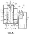
単一図に概略を示す装置は本発明の趣旨に合致した処理装置10である。この装置は、特に、熱塑性材料の容器の内面へ低圧プラズマによる被覆の堆積方法の実施をはかるためのものである。
【0014】
たとえば、容器はテレフタル酸ポリエチレン(PET)製ボトルとすることができ、形成すべき被覆はカーボンを主とする材料で構成することができる。しかしながら本発明は、他の容器、ならびに、たとえば酸化ケイ素または酸化アルミニウムを主材とする被覆などについて有利に実施することができよう。事実、これらの被覆はすべて酸素および過酸化炭素などの気体に対するPET製ボトルの透過性を大幅に減らすことができるため、きわめて有利である。
【0015】
処理装置10は一度に1つのボトルを処理するようになっている。しかしながらこの処理装置は、一連の同一な装置を含む回転機械内に組み込まれるのが好ましい、というのは、所与の時間内に多数のボトルを処理することができるようにする目的からである。
【0016】
したがって装置10は、たとえば金属などの導体材料の外部チャンバ12を含む。チャンバ12は軸A1を中心として円筒形であり、本発明によれば、マイクロ波型電磁場の特別結合モードを容易にするように寸法が決められる。
【0017】
事実、装置10は、チャンバ12の外部に配置され、マイクロ波領域の電磁界を発生することができる発生器14を含む。発生器14によって発生されるマイクロ波の電界周波数はたとえば2.45GHzである。
【0018】
発生器14はチャンバ12の外部の箱13内に取り付けられ、発生器が発生する電磁放射は、円筒形チャンバの半径方向に延び、チャンバのほぼ中間の高さのところのチャンバ内に設けられた窓を通して開口するトンネル形状の導波路15により、チャンバ12まで送られる。
【0019】
以下で詳細に開示するように、導波路15の形状および寸法も、チャンバ12内でのマイクロ波電界の好ましい結合ができるように調節される。
【0020】
チャンバ12の内部には、チャンバと同軸であり、マイクロ波をほぼ透過し、チャンバ12の内部において、チャンバ12に同軸な円筒形キャビティ18を画定する管16を配置した。管16はたとえば石英で作成される。キャビティ18は、その軸端のうちの1つ、この例では下端において、チャンバ12の下部横断隔壁26により閉じられる。反対にキャビティ18の上端は、ボトルが処理を受けることになるキャビティの内部にボトルを挿入することができるように開口している。ボトルは、チャンバ12およびキャビティ18に対しほぼ同軸に配置される。
【0021】
蓋20は、キャビティ内を真空にできるようにキャビティ18の上端を気密的に閉じるためのものである。容器24をキャビティ18の内部に挿入できるよう、蓋20は軸方向において可動である。
【0022】
蓋20上には、ネックで容器24を固定するための手段22と、キャビティ18内に様々な水準の真空を作り出す手段とが設けられる。したがってたとえば、容器の内面の処理の場合、およそ0.1mbarの絶対圧力に相当する真空を容器24に作り、ボトルの外部には、およそ50mbarの絶対圧力に相当する真空を作る。容器24の周囲に作られる真空により、容器が、その変形をもたらす可能性のある過大な圧力差を受けるのが防止される。しかしながらこの真空度はプラズマの形成を可能にするほど高くはない。それは、マイクロ波により供給されるエネルギーが、堆積を所望しないボトルの外側に散逸しないようにするためである。別の動作モードは、プラズマが開始できないよう、たとえば0.01mbar未満の十分に低い真空を容器24の周囲に作ることである。この動作モードは技術的にあまり有利ではない。なぜなら、この低い圧力レベルに到達するまで、より多くの時間を要するからである。
【0023】
もちろん蓋20は、チャンバ内、すなわちここでは容器24の内部に、容器の内部隔壁上に堆積させたい材料の少なくとも1つの前駆体を含む反応流体を注入するための手段も含む。容器24の処理には、堆積方法に対し追加となる方法の実施も含まれることに留意されたい。したがって、堆積を実行する前、あるいは堆積の後処理を実行する前に、容器の表面の第1準備処理を実行することを考えることができる。
【0024】
本装置は、石英管16の周囲のチャンバ12内に配置された軸A1の環状板28、30も含む。2つの環状板28、30は、導波路15がチャンバ12内に開口する際に通過する窓の両側に軸方向に配置されるように、相互に軸方向に変位している。しかしながら、それぞれの軸の位置は、処理すべき容器24の形状に応じて変化することができる。事実、導電材料で作製される環状板28、30は、チャンバ12内に投入される電磁界のための短絡を形成し、有効処理ゾーンのレベルにおいて強度の最大値を得るために電界を軸方向に閉じ込める。したがって環状板28、30は、環状板の軸位置の迅速かつ容易な調整を可能にする軸方向滑動ロッド32、34により支承される。
【0025】
本発明によれば、提供される装置により、チャンバの内部において、可能な限り高い均質性を有するプラズマを得ることができる。これを行うためには、電磁界強度が可能な限り均一に分布すること、および特に、チャンバのある点における電界強度が、当該点の軸位置とはほぼ無関係であること、また、軸A1を中心とするこの点の角度位置ともほぼ無関係であることが必要である。
【0026】
これを行うのに、以下に記述するような処理位置により最良の結果が得られたことがわかった。
【0027】
導波路15は、軸A1に対し半径方向に延びることを見てきたが、軸A1からほぼ185mmのところに配置される底面隔壁36により、半径方向において外側に画定される。導波路15は、軸A1方向の高さがおよそ43mm、幅がおよそ86mmの一定矩形断面を有する。
【0028】
発生器14は、導波路の下部隔壁内に設けられた開口部から導波路15内に入るそのアンテナ38が、底面隔壁36に対し半径方向に、発生器の製造者により推奨された、あらかじめ決められた距離に配置される。
【0029】
しかしながら、電磁界強度の最適な分布を得るための決定的なパラメータはチャンバ12の内径であることがわかった。
【0030】
事実、2.45GHzのマイクロ波発生器の使用の一環として、以下の3つの場合に関してきわめて納得のゆく結果が得られた。
【0031】
− チャンバの内径が213mmから217mmで、容器がなく、キャビティ内が真空でない状態では、電界強度の変化はチャンバの半径上で2つの最大値を有する。
【0032】
− チャンバの内径が334mmから340mmで、容器がなく、キャビティ内が真空でない状態では、電界強度の変化はチャンバの半径上で3つの最大値を有する。
【0033】
− チャンバの内径が455mmから465mmで、容器がなく、キャビティ内が真空でない状態では、電界強度の変化はチャンバの半径上で4つの最大値を有する。
【0034】
これらの結果は、チャンバ内に存在する電磁界の像を得るために、チャンバの内部において種々の方向(半径方向、外周方向、横断方向)に感熱紙を配置することにより明らかにすることができる。3つの場合、電磁界が軸A1を中心とする軸回転対称を有していることに注目することができた。
【0035】
およそ215mmの内径を有するチャンバの場合、たとえば、およそ85mmの内径を有する石英管16を使用することができる。このような装置を用いた試験により、500mlの体積のPET製ボトルの内面に、炭素を主とする材料の均質な被覆を毎秒300〜400オングストローム程度の平均堆積速度で付着させることができた。したがって、有効バリア層を得ることができる処理時間は1〜3秒程度であり、産業レベルでこの装置を使用することが可能である。
【0036】
以上の如く、本発明により、特にバリア特性に関して必要な全品質を有する堆積を容器の内部隔壁上できわめて短時間に実行するための実用的装置を得ることが可能である。さらにこの装置は十分に単純でコンパクトであるため、1時間あたりに多数の容器を処理することができる回転機械上に設置することができる。
【0037】
さらにこのような装置は、たとえば、材料の堆積を発生しないが、プラズマ状態になった時、容器を構成する材料の構造の表面を変化させる酸素、窒素、またはアルゴンなどの気体または混合気を使用する処理など、被覆の堆積以外の種類の処理を実行するのに使用することができる。この装置は容器の外表面を処理するのに使用することもできる。その場合、当然のことながら反応流体はキャビティ内ではあるが容器の外側に注入されなければならない。
【図面の簡単な説明】
【図1】 本発明の趣旨に合致した装置の概略図である。[0001]
The present invention relates to the field of surface treatment methods, for example on containers of thermoplastic material.
[0002]
The invention applies, for example, to the field of depositing a thin layer having a barrier effect on a bottle or pot of thermoplastic material such as polyethylene terephthalate.
[0003]
At present, in order to increase the shelf life of the products filled in these containers, in particular to reduce their gas permeability or increase their impermeability to certain radiation, especially ultraviolet light, the barrier properties of these containers are improved. Attempts have been made to improve.
[0004]
For this purpose, various methods have been proposed aiming at coating the container with an organic or inorganic material layer that can directly change the material of the container at least on the surface or improve the properties of the container. A very advantageous method for realizing such a process is to perform the process using a low-pressure plasma. In such a method, a vacuum is created inside the chamber and at the same time the reaction fluid is injected, preferably under an absolute pressure of less than 1 mbar. The reaction fluid depends on the nature of the material being deposited. The reaction fluid usually contains a precursor of the material to be deposited, in the form of a gas or gas mixture. The reaction fluid can also include a carrier gas.
[0005]
This reaction fluid is controlled by microwave electromagnetic radiation suitable for exciting a precursor to form a plasma that produces active molecules. In the case of a deposition process, these molecules can be deposited on the surface of the container by extremely strong physicochemical bonds that ensure the stability of the deposited material. In some cases, however, the treatment may simply be to modify the surface of the material comprising the container. In that case, there is no deposition of a new material layer and there is a denaturation of the material of the vessel by interaction with the active molecules of the plasma or the like.
[0006]
By using microwave-type electromagnetic radiation, it is possible to obtain a deposit having a special structure that cannot be obtained with other radiation, especially the widely used radio frequency-type radiation.
[0007]
One of the difficulties faced in the implementation of these methods resides in obtaining a homogeneity of treatment of the entire surface to be coated. In the case of a deposition process, these homogeneity issues can affect the thickness of the deposited layer and the composition of this layer. Of course, this poor uniformity of the deposited layer is not satisfactory.
[0008]
By the way, the realization of the homogeneous treatment is performed by using a plasma having a particularly high homogeneity.
[0009]
The object of the present invention is therefore to provide a device capable of obtaining an optimal propagation of microwaves which can guarantee good plasma homogeneity. In the case of a deposition process, the apparatus must also make it possible to obtain this homogeneity with a processing time compatible with industrial use, ie with a relatively high deposition rate.
[0010]
For this purpose, the present invention is a type in which processing is performed by a microwave type electromagnetic wave using low-pressure plasma by excitation of a reaction fluid, and a microwave is introduced into a container through a coupling device. A device for treating the surface of a container of the kind installed in a chamber of conductive material, wherein the chamber is a rotating cylinder about the main axis of the container, and the coupling device is substantially perpendicular to the axis of the chamber. Including a waveguide tunnel that extends into a side wall of the chamber in the form of a window that extends in any direction and has a rectangle whose short side corresponds to a dimension in the direction of the axis of the chamber in a projection on the tangential plane of the chamber; There is provided an apparatus characterized in that the inner diameter is such that an electric field generated by the propagation of microwaves propagates mainly in a chamber in a mode having axial rotational symmetry.
[0011]
According to another aspect of the invention,
When the microwave is injected into the chamber without the container, the change in electric field strength has two maximum values on the radius of the chamber;
The microwave has a frequency of 2.45 GHz and the inner diameter of the chamber is 213 mm to 217 mm;
-When microwaves are injected into the chamber without a container, the change in field strength has three maximum values on the radius of the chamber;
The microwave has a frequency of 2.45 GHz and the inner diameter of the chamber is 334 mm to 340 mm;
When the microwave is injected into the chamber without the container, the change in electric field strength has four maximum values on the radius of the chamber;
The microwave has a frequency of 2.45 GHz and the inner diameter of the chamber is 455 mm to 465 mm;
The waveguide tunnel has a rectangular cross section;
The microwave has a frequency of 2.45 GHz and the cross section of the waveguide tunnel has a dimension of approximately 43 mm in the axial direction of the chamber and a dimension of approximately 86 mm in the perpendicular direction;
-The reaction fluid is introduced into the container so that the treatment is carried out on the inner surface of the container;
-The reaction fluid is put into a chamber outside the container so that the treatment takes place on the outer surface of the container;
-Inside the chamber, a cavity is defined by a septum made of a material that is substantially transparent to microwaves, and a container is housed inside the cavity;
The treatment comprises depositing the material with a low-pressure plasma;
[0012]
Other features of the present invention will become apparent upon reading the following detailed description and upon reference to the accompanying drawings in which a single drawing outlines an apparatus consistent with the spirit of the invention.
[0013]
The apparatus schematically shown in a single figure is a
[0014]
For example, the container can be a polyethylene terephthalate (PET) bottle, and the coating to be formed can be composed of a carbon-based material. However, the invention may be advantageously practiced with other containers, as well as coatings based on, for example, silicon oxide or aluminum oxide. In fact, all these coatings are very advantageous because they can greatly reduce the permeability of PET bottles to gases such as oxygen and carbon peroxide.
[0015]
The
[0016]
Thus, the
[0017]
In fact, the
[0018]
The
[0019]
As will be disclosed in detail below, the shape and dimensions of the
[0020]
Arranged inside the
[0021]
The
[0022]
On the
[0023]
Of course, the
[0024]
The apparatus also includes an
[0025]
According to the present invention, a plasma having the highest possible homogeneity can be obtained inside the chamber by the provided apparatus. To do this, the field strength is distributed as uniformly as possible, and in particular that the electric field strength at a point in the chamber is almost independent of the axial position of the point, and the axis A1 is It needs to be almost independent of the angular position of this point as the center.
[0026]
To do this, it was found that the best results were obtained with processing positions as described below.
[0027]
The
[0028]
The
[0029]
However, it has been found that the critical parameter for obtaining the optimal distribution of electromagnetic field strength is the inner diameter of the
[0030]
In fact, as part of the use of a 2.45 GHz microwave generator, very satisfactory results were obtained for the following three cases:
[0031]
-With a chamber inner diameter of 213 mm to 217 mm, no container and no vacuum in the cavity, the change in electric field strength has two maxima on the chamber radius.
[0032]
-With a chamber inner diameter of 334 mm to 340 mm, no container, and no vacuum in the cavity, the change in electric field strength has three maximum values on the radius of the chamber.
[0033]
-With a chamber inner diameter of 455 mm to 465 mm, no container, and no vacuum in the cavity, the change in electric field strength has four maximum values on the radius of the chamber.
[0034]
These results can be clarified by placing thermal paper in various directions (radial, circumferential, transverse) in the chamber to obtain an image of the electromagnetic field present in the chamber. . In the three cases, it could be noted that the electromagnetic field has axial rotation symmetry about the axis A1.
[0035]
For a chamber having an inner diameter of approximately 215 mm, for example, a
[0036]
As described above, according to the present invention, it is possible to obtain a practical apparatus for executing deposition having the total quality required particularly on the barrier properties on the inner partition wall of the container in a very short time. Furthermore, the device is sufficiently simple and compact that it can be installed on a rotating machine capable of processing a large number of containers per hour.
[0037]
Further, such an apparatus uses a gas or gas mixture such as oxygen, nitrogen, or argon that does not cause material deposition, but changes the surface of the material structure that makes up the vessel when in a plasma state, for example. Can be used to perform other types of processing than coating deposition. This device can also be used to treat the outer surface of the container. In that case, of course, the reaction fluid must be injected into the cavity but outside the container.
[Brief description of the drawings]
FIG. 1 is a schematic diagram of an apparatus consistent with the spirit of the present invention.
Claims (13)
Translated fromJapaneseチャンバ(12)が、容器(24)の主軸(A1)を中心とする回転対称の円筒であること、結合装置が、チャンバの軸(A1)に対しほぼ直角な方向に延び、短辺がチャンバの軸の方向の寸法に対応する矩形をチャンバの接線面上の投影において呈する窓の形状のチャンバの側壁内に開口する導波トンネル(15)を含むこと、およびチャンバ(12)の内径が、マイクロ波の伝播によって生じる電界が軸回転対称を呈するモードでマイクロ波がチャンバ内を主に伝播するような内径であることを特徴とする装置。Installationprocess,subjectedLimited by the electromagnetic wave of the microwave type using a low-pressure plasma by excitation of the reactionfluid and the container, the chamber of the conductive material microwave is introduced via a coupling device (12) An apparatus for treating the surface ofa container,
The chamber (12) is a rotationallysymmetric cylinder about the main axis (A1) of the container (24), the coupling device extends in a direction substantially perpendicular to the chamber axis (A1), and the short side is the chamber. Including a waveguide tunnel (15) that opens into the side wall of the chamber in the shape of a window that presents a rectangle corresponding to a dimension in the axial direction of the chamber, and the inner diameter of the chamber (12), An apparatus having an inner diameter such that the microwave mainly propagates in the chamber in a mode in which the electric field generated by the propagation of the microwave exhibits axial rotation symmetry.
Applications Claiming Priority (3)
| Application Number | Priority Date | Filing Date | Title |
|---|---|---|---|
| FR99/06178 | 1999-04-29 | ||
| FR9906178AFR2792854B1 (en) | 1999-04-29 | 1999-04-29 | DEVICE FOR MICROWAVE PLASMA DEPOSITION OF A COATING ON A CONTAINER OF THERMOPLASTIC MATERIAL |
| PCT/FR2000/000916WO2000066804A1 (en) | 1999-04-29 | 2000-04-11 | Device for treating a container with microwave plasma |
Publications (2)
| Publication Number | Publication Date |
|---|---|
| JP2002543292A JP2002543292A (en) | 2002-12-17 |
| JP3735257B2true JP3735257B2 (en) | 2006-01-18 |
Family
ID=9545610
Family Applications (1)
| Application Number | Title | Priority Date | Filing Date |
|---|---|---|---|
| JP2000615424AExpired - Fee RelatedJP3735257B2 (en) | 1999-04-29 | 2000-04-11 | Container processing equipment using microwave plasma |
Country Status (15)
| Country | Link |
|---|---|
| US (1) | US7670453B1 (en) |
| EP (1) | EP1198611B9 (en) |
| JP (1) | JP3735257B2 (en) |
| KR (1) | KR100467160B1 (en) |
| CN (1) | CN1158405C (en) |
| AT (1) | ATE244320T1 (en) |
| AU (1) | AU772766B2 (en) |
| BR (1) | BR0010064B1 (en) |
| CA (1) | CA2370337C (en) |
| DE (1) | DE60003690T2 (en) |
| ES (1) | ES2202094T3 (en) |
| FR (1) | FR2792854B1 (en) |
| MX (1) | MXPA01010669A (en) |
| PT (1) | PT1198611E (en) |
| WO (1) | WO2000066804A1 (en) |
Families Citing this family (18)
| Publication number | Priority date | Publication date | Assignee | Title |
|---|---|---|---|---|
| DE10138697B4 (en)* | 2001-08-07 | 2005-02-24 | Schott Ag | Method and device for coating and spray-blowing a three-dimensional body |
| US7926446B2 (en)* | 2002-05-24 | 2011-04-19 | Schott Ag | Multi-place coating apparatus and process for plasma coating |
| EP1572786A2 (en)* | 2002-11-12 | 2005-09-14 | Dow Global Technologies Inc. | Process and apparatus for depositing plasma coating onto a container |
| CN100347229C (en)* | 2002-11-12 | 2007-11-07 | 陶氏环球技术公司 | Method and apparatus for depositing a plasma coating in a vessel |
| FR2847912B1 (en)* | 2002-11-28 | 2005-02-18 | Sidel Sa | METHOD AND DEVICE FOR PLASMA MICROWAVE DEPOSITION A COATING ON A SIDE OF A CONTAINER IN THERMOPLASTIC MATERIAL |
| DE10331946B4 (en)* | 2003-07-15 | 2008-06-26 | Schott Ag | Device for the treatment of workpieces |
| JP3970229B2 (en)* | 2003-09-10 | 2007-09-05 | 三菱重工食品包装機械株式会社 | Vacuum processing equipment |
| EP1595913A1 (en)* | 2004-05-14 | 2005-11-16 | Inergy Automotive Systems Research (SA) | Method for preparing a hollow element of a fuel system |
| FR2871813B1 (en)* | 2004-06-17 | 2006-09-29 | Sidel Sas | DEVICE FOR PLASMA MICROWAVE DEPOSITION OF A COATING ON A SIDE OF A CONTAINER IN THERMOPLASTIC MATERIAL |
| FR2872555B1 (en)* | 2004-06-30 | 2006-10-06 | Sidel Sas | VACUUM PUMPING CIRCUIT AND CONTAINER TREATMENT MACHINE EQUIPPED WITH SAID CIRCUIT |
| MX2007004481A (en)* | 2004-10-13 | 2007-05-09 | Dow Global Technologies Inc | Process for plasma coating. |
| FR2892425B1 (en)* | 2005-10-24 | 2008-01-04 | Sidel Sas | COOLING APPARATUS FOR PLASMA DEPOSITION OF A BARRIER LAYER ON A CONTAINER. |
| FR2903622B1 (en)* | 2006-07-17 | 2008-10-03 | Sidel Participations | DEVICE FOR DEPOSITING A COATING ON AN INTERNAL SIDE OF A CONTAINER |
| FR2908009B1 (en) | 2006-10-25 | 2009-02-20 | Sidel Participations | METHOD AND DEVICE FOR CONTROLLING THE ELECTRIC POWER SUPPLY OF A MAGNETRON, AND INSTALLATION FOR TREATING THERMOPLASTIC CONTAINERS WHICH MAKES IT APPLY |
| FR2932395B1 (en)* | 2008-06-13 | 2011-06-10 | Sidel Participations | METHOD FOR PROTECTING MEASURING APPARATUS (S) OR OTHER (S) |
| US10081864B2 (en) | 2011-03-10 | 2018-09-25 | Kaiatech, Inc | Method and apparatus for treating containers |
| FR3091875B1 (en) | 2019-01-17 | 2021-09-24 | Innovative Systems Et Tech Isytech | Process and treatment device for the deposition of a barrier effect coating |
| KR102596216B1 (en) | 2021-10-29 | 2023-11-01 | 현대제철 주식회사 | Galvanizing steel sheet and manufacturing method thereof |
Family Cites Families (17)
| Publication number | Priority date | Publication date | Assignee | Title |
|---|---|---|---|---|
| JPH0740566B2 (en)* | 1986-02-04 | 1995-05-01 | 株式会社日立製作所 | Plasma processing method and apparatus |
| KR960014434B1 (en)* | 1987-12-09 | 1996-10-15 | 후세 노보루 | Plasma processing equipment |
| US4893584A (en)* | 1988-03-29 | 1990-01-16 | Energy Conversion Devices, Inc. | Large area microwave plasma apparatus |
| FR2631199B1 (en)* | 1988-05-09 | 1991-03-15 | Centre Nat Rech Scient | PLASMA REACTOR |
| DE69004908T2 (en)* | 1989-09-20 | 1994-03-24 | Sumitomo Electric Industries | Device for the synthesis of diamonds. |
| DE4203369C2 (en)* | 1992-02-06 | 1994-08-11 | Ceramoptec Gmbh | Method and device for producing preforms for optical fibers |
| US5225740A (en)* | 1992-03-26 | 1993-07-06 | General Atomics | Method and apparatus for producing high density plasma using whistler mode excitation |
| DE4316349C2 (en)* | 1993-05-15 | 1996-09-05 | Ver Foerderung Inst Kunststoff | Process for the internal coating of hollow bodies with organic cover layers by plasma polymerization, and device for carrying out the process |
| US5679412A (en)* | 1993-10-28 | 1997-10-21 | Manfred R. Kuehnle | Method and apparatus for producing gas impermeable, chemically inert container structures for food and volatile substances |
| US5565248A (en)* | 1994-02-09 | 1996-10-15 | The Coca-Cola Company | Method and apparatus for coating hollow containers through plasma-assisted deposition of an inorganic substance |
| BR9505649A (en)* | 1994-02-16 | 1996-03-19 | Coca Cola Co | Process and system for forming a polymer coating on a container surface and system and process for forming an inert / impermeable inner surface of a container |
| KR970071945A (en)* | 1996-02-20 | 1997-11-07 | 가나이 쯔도무 | Plasma treatment method and apparatus |
| JPH09321030A (en)* | 1996-05-31 | 1997-12-12 | Tokyo Electron Ltd | Microwave plasma treatment apparatus |
| TW392215B (en)* | 1997-02-19 | 2000-06-01 | Anelva Corp | Surface processing apparatus |
| DE19722205A1 (en)* | 1997-05-27 | 1998-12-03 | Leybold Systems Gmbh | Method and device for coating plastic or glass containers by means of a PCVD coating method |
| PL339616A1 (en)* | 1997-09-30 | 2001-01-02 | Tetra Laval Holdings & Finance | Method of and apparatus for treating internal surface of a plastic bottle in a plasma-assisted process |
| FR2776540B1 (en)* | 1998-03-27 | 2000-06-02 | Sidel Sa | BARRIER-EFFECT CONTAINER AND METHOD AND APPARATUS FOR ITS MANUFACTURING |
- 1999
- 1999-04-29FRFR9906178Apatent/FR2792854B1/ennot_activeExpired - Fee Related
- 2000
- 2000-04-11CNCNB008069026Apatent/CN1158405C/ennot_activeExpired - Lifetime
- 2000-04-11JPJP2000615424Apatent/JP3735257B2/ennot_activeExpired - Fee Related
- 2000-04-11ATAT00918933Tpatent/ATE244320T1/ennot_activeIP Right Cessation
- 2000-04-11AUAU39712/00Apatent/AU772766B2/ennot_activeCeased
- 2000-04-11CACA002370337Apatent/CA2370337C/ennot_activeExpired - Fee Related
- 2000-04-11WOPCT/FR2000/000916patent/WO2000066804A1/enactiveIP Right Grant
- 2000-04-11KRKR10-2001-7013643Apatent/KR100467160B1/ennot_activeExpired - Fee Related
- 2000-04-11MXMXPA01010669Apatent/MXPA01010669A/enactiveIP Right Grant
- 2000-04-11DEDE60003690Tpatent/DE60003690T2/ennot_activeExpired - Lifetime
- 2000-04-11USUS10/501,718patent/US7670453B1/ennot_activeExpired - Fee Related
- 2000-04-11BRBRPI0010064-1Apatent/BR0010064B1/ennot_activeIP Right Cessation
- 2000-04-11PTPT00918933Tpatent/PT1198611E/enunknown
- 2000-04-11EPEP00918933Apatent/EP1198611B9/ennot_activeExpired - Lifetime
- 2000-04-11ESES00918933Tpatent/ES2202094T3/ennot_activeExpired - Lifetime
Also Published As
| Publication number | Publication date |
|---|---|
| DE60003690T2 (en) | 2004-06-03 |
| CA2370337A1 (en) | 2000-11-09 |
| BR0010064A (en) | 2002-01-15 |
| ES2202094T3 (en) | 2004-04-01 |
| DE60003690D1 (en) | 2003-08-07 |
| CN1158405C (en) | 2004-07-21 |
| PT1198611E (en) | 2003-11-28 |
| AU3971200A (en) | 2000-11-17 |
| CA2370337C (en) | 2004-10-12 |
| CN1349567A (en) | 2002-05-15 |
| EP1198611B1 (en) | 2003-07-02 |
| EP1198611B9 (en) | 2003-11-05 |
| ATE244320T1 (en) | 2003-07-15 |
| KR20020028874A (en) | 2002-04-17 |
| FR2792854A1 (en) | 2000-11-03 |
| KR100467160B1 (en) | 2005-01-24 |
| US7670453B1 (en) | 2010-03-02 |
| AU772766B2 (en) | 2004-05-06 |
| EP1198611A1 (en) | 2002-04-24 |
| BR0010064B1 (en) | 2010-10-05 |
| FR2792854B1 (en) | 2001-08-03 |
| WO2000066804A1 (en) | 2000-11-09 |
| JP2002543292A (en) | 2002-12-17 |
| MXPA01010669A (en) | 2003-10-15 |
Similar Documents
| Publication | Publication Date | Title |
|---|---|---|
| JP3735257B2 (en) | Container processing equipment using microwave plasma | |
| US6376028B1 (en) | Device and method for treating the inside surface of a plastic container with a narrow opening in a plasma enhanced process | |
| JPH08208860A (en) | Apparatus for surface-treating hollow member | |
| US20030159654A1 (en) | Apparatus for plasma treatment of dielectric bodies | |
| KR0145302B1 (en) | Formation method of thin film | |
| CA1281082C (en) | Apparatus for producing a plasma and for the treatment of substrates therein | |
| US5517085A (en) | Apparatus including ring-shaped resonators for producing microwave plasmas | |
| JP3070037B2 (en) | Method of attaching barrier film to three-dimensional article | |
| KR960014436B1 (en) | Large area microwave plasma apparatus | |
| KR101401826B1 (en) | Low temperature plasma treatment method of plastic bottle | |
| CN101645386B (en) | Device and method for plasma treating hollow bodies | |
| JP4732685B2 (en) | Equipment for coating articles | |
| KR20050086510A (en) | Process and apparatus for depositing plasma coating onto a container | |
| EP0547868A1 (en) | Apparatus and method for controlling plasma size and position in plasma-activated chemical vapor deposition processes | |
| KR960043012A (en) | Plasma processing method and apparatus | |
| JPH10330945A (en) | Method for coating hollow body, device for coating hollow body and vessel having at least one closable opening | |
| US20090229521A1 (en) | Method and device for microwave plasma deposition of a coating on a thermoplastic container surface | |
| US11898241B2 (en) | Method for a treatment to deposit a barrier coating | |
| WO1997044503A1 (en) | Method and apparatus for treating inside surfaces of containers | |
| US5324362A (en) | Apparatus for treating substrates in a microwave-generated gas-supported plasma | |
| KR100430641B1 (en) | Method and apparatus for plasma processing | |
| JP4752503B2 (en) | Microwave plasma processing method | |
| JPH08165194A (en) | Method and device for forming thin film with microwave plasma cvd | |
| BR112021013958B1 (en) | METHOD FOR TREATMENT IN A WRAP OF AN INTERNAL SURFACE OF A CONTAINER MADE OF POLYMERIC MATERIAL, AND DEVICE FOR TREATMENT OF AN INTERNAL SURFACE OF A CONTAINER MADE OF POLYMERIC MATERIAL | |
| JPH01117317A (en) | plasma equipment |
Legal Events
| Date | Code | Title | Description |
|---|---|---|---|
| A131 | Notification of reasons for refusal | Free format text:JAPANESE INTERMEDIATE CODE: A131 Effective date:20050607 | |
| A521 | Request for written amendment filed | Free format text:JAPANESE INTERMEDIATE CODE: A523 Effective date:20050906 | |
| TRDD | Decision of grant or rejection written | ||
| A01 | Written decision to grant a patent or to grant a registration (utility model) | Free format text:JAPANESE INTERMEDIATE CODE: A01 Effective date:20051004 | |
| A61 | First payment of annual fees (during grant procedure) | Free format text:JAPANESE INTERMEDIATE CODE: A61 Effective date:20051021 | |
| R150 | Certificate of patent or registration of utility model | Ref document number:3735257 Country of ref document:JP Free format text:JAPANESE INTERMEDIATE CODE: R150 Free format text:JAPANESE INTERMEDIATE CODE: R150 | |
| FPAY | Renewal fee payment (event date is renewal date of database) | Free format text:PAYMENT UNTIL: 20091028 Year of fee payment:4 | |
| R250 | Receipt of annual fees | Free format text:JAPANESE INTERMEDIATE CODE: R250 | |
| FPAY | Renewal fee payment (event date is renewal date of database) | Free format text:PAYMENT UNTIL: 20101028 Year of fee payment:5 | |
| R250 | Receipt of annual fees | Free format text:JAPANESE INTERMEDIATE CODE: R250 | |
| FPAY | Renewal fee payment (event date is renewal date of database) | Free format text:PAYMENT UNTIL: 20111028 Year of fee payment:6 | |
| R250 | Receipt of annual fees | Free format text:JAPANESE INTERMEDIATE CODE: R250 | |
| FPAY | Renewal fee payment (event date is renewal date of database) | Free format text:PAYMENT UNTIL: 20111028 Year of fee payment:6 | |
| FPAY | Renewal fee payment (event date is renewal date of database) | Free format text:PAYMENT UNTIL: 20121028 Year of fee payment:7 | |
| R250 | Receipt of annual fees | Free format text:JAPANESE INTERMEDIATE CODE: R250 | |
| FPAY | Renewal fee payment (event date is renewal date of database) | Free format text:PAYMENT UNTIL: 20121028 Year of fee payment:7 | |
| FPAY | Renewal fee payment (event date is renewal date of database) | Free format text:PAYMENT UNTIL: 20131028 Year of fee payment:8 | |
| R250 | Receipt of annual fees | Free format text:JAPANESE INTERMEDIATE CODE: R250 | |
| R250 | Receipt of annual fees | Free format text:JAPANESE INTERMEDIATE CODE: R250 | |
| R250 | Receipt of annual fees | Free format text:JAPANESE INTERMEDIATE CODE: R250 | |
| R250 | Receipt of annual fees | Free format text:JAPANESE INTERMEDIATE CODE: R250 | |
| R250 | Receipt of annual fees | Free format text:JAPANESE INTERMEDIATE CODE: R250 | |
| R250 | Receipt of annual fees | Free format text:JAPANESE INTERMEDIATE CODE: R250 | |
| R250 | Receipt of annual fees | Free format text:JAPANESE INTERMEDIATE CODE: R250 | |
| LAPS | Cancellation because of no payment of annual fees |