JP3734236B2 - Electric vehicle air conditioner power supply input circuit - Google Patents
Electric vehicle air conditioner power supply input circuitDownload PDFInfo
- Publication number
- JP3734236B2 JP3734236B2JP34008397AJP34008397AJP3734236B2JP 3734236 B2JP3734236 B2JP 3734236B2JP 34008397 AJP34008397 AJP 34008397AJP 34008397 AJP34008397 AJP 34008397AJP 3734236 B2JP3734236 B2JP 3734236B2
- Authority
- JP
- Japan
- Prior art keywords
- voltage
- electric vehicle
- input circuit
- charging
- air conditioner
- Prior art date
- Legal status (The legal status is an assumption and is not a legal conclusion. Google has not performed a legal analysis and makes no representation as to the accuracy of the status listed.)
- Expired - Fee Related
Links
- 239000003990capacitorSubstances0.000claimsdescription32
- 238000004378air conditioningMethods0.000claimsdescription30
- 238000001514detection methodMethods0.000description36
- 230000000052comparative effectEffects0.000description9
- 238000010586diagramMethods0.000description5
- 230000000903blocking effectEffects0.000description3
- 230000000694effectsEffects0.000description2
- 238000007599dischargingMethods0.000description1
- 238000009413insulationMethods0.000description1
- 238000012423maintenanceMethods0.000description1
- 238000000034methodMethods0.000description1
Images


Classifications
- B—PERFORMING OPERATIONS; TRANSPORTING
- B60—VEHICLES IN GENERAL
- B60L—PROPULSION OF ELECTRICALLY-PROPELLED VEHICLES; SUPPLYING ELECTRIC POWER FOR AUXILIARY EQUIPMENT OF ELECTRICALLY-PROPELLED VEHICLES; ELECTRODYNAMIC BRAKE SYSTEMS FOR VEHICLES IN GENERAL; MAGNETIC SUSPENSION OR LEVITATION FOR VEHICLES; MONITORING OPERATING VARIABLES OF ELECTRICALLY-PROPELLED VEHICLES; ELECTRIC SAFETY DEVICES FOR ELECTRICALLY-PROPELLED VEHICLES
- B60L1/00—Supplying electric power to auxiliary equipment of vehicles
- B60L1/02—Supplying electric power to auxiliary equipment of vehicles to electric heating circuits
- B—PERFORMING OPERATIONS; TRANSPORTING
- B60—VEHICLES IN GENERAL
- B60H—ARRANGEMENTS OF HEATING, COOLING, VENTILATING OR OTHER AIR-TREATING DEVICES SPECIALLY ADAPTED FOR PASSENGER OR GOODS SPACES OF VEHICLES
- B60H1/00—Heating, cooling or ventilating [HVAC] devices
- B60H1/00357—Air-conditioning arrangements specially adapted for particular vehicles
- B60H1/00385—Air-conditioning arrangements specially adapted for particular vehicles for vehicles having an electrical drive, e.g. hybrid or fuel cell
- B60H1/00392—Air-conditioning arrangements specially adapted for particular vehicles for vehicles having an electrical drive, e.g. hybrid or fuel cell for electric vehicles having only electric drive means
- B—PERFORMING OPERATIONS; TRANSPORTING
- B60—VEHICLES IN GENERAL
- B60H—ARRANGEMENTS OF HEATING, COOLING, VENTILATING OR OTHER AIR-TREATING DEVICES SPECIALLY ADAPTED FOR PASSENGER OR GOODS SPACES OF VEHICLES
- B60H1/00—Heating, cooling or ventilating [HVAC] devices
- B60H1/00421—Driving arrangements for parts of a vehicle air-conditioning
- B60H1/00428—Driving arrangements for parts of a vehicle air-conditioning electric
- Y—GENERAL TAGGING OF NEW TECHNOLOGICAL DEVELOPMENTS; GENERAL TAGGING OF CROSS-SECTIONAL TECHNOLOGIES SPANNING OVER SEVERAL SECTIONS OF THE IPC; TECHNICAL SUBJECTS COVERED BY FORMER USPC CROSS-REFERENCE ART COLLECTIONS [XRACs] AND DIGESTS
- Y02—TECHNOLOGIES OR APPLICATIONS FOR MITIGATION OR ADAPTATION AGAINST CLIMATE CHANGE
- Y02T—CLIMATE CHANGE MITIGATION TECHNOLOGIES RELATED TO TRANSPORTATION
- Y02T10/00—Road transport of goods or passengers
- Y02T10/80—Technologies aiming to reduce greenhouse gasses emissions common to all road transportation technologies
- Y02T10/88—Optimized components or subsystems, e.g. lighting, actively controlled glasses
Landscapes
- Engineering & Computer Science (AREA)
- Mechanical Engineering (AREA)
- Physics & Mathematics (AREA)
- Thermal Sciences (AREA)
- Power Engineering (AREA)
- Life Sciences & Earth Sciences (AREA)
- Sustainable Development (AREA)
- Sustainable Energy (AREA)
- Transportation (AREA)
- Electric Propulsion And Braking For Vehicles (AREA)
- Inverter Devices (AREA)
Description
Translated fromJapanese【0001】
【発明の属する技術分野】
本発明は、主として電気自動車に搭載される空調装置を制御する空調制御装置の電気回路であって、空調装置の圧縮機を駆動する駆動装置へ高圧直流電源からの高圧直流電流を供給する電気自動車用空調装置の電源入力回路に関する。
【0002】
【従来の技術】
従来、この種の電気自動車用空調装置の電源入力回路を含む空調制御装置としては、例えば図3に示すような構成のものが挙げられる。
【0003】
この空調制御装置1´は、電気自動車に搭載される空調装置の圧縮機へ供給される高圧直流電源3からの高圧直流電流を遮断する電流遮断装置である正極側電流遮断装置4a及び負極側電流遮断装置4bと、高圧直流電流を交流電源に変換して圧縮機を駆動する駆動装置であるインバータ6と、インバータ6に接続される圧縮機のモータ(以下、コンプレッサモータとする)7と、高圧直流電源3からの高圧直流電流をインバータ6へ供給する電源入力回路と、負極側電流遮断装置4b及びインバータ6間の接続線に接続され、高圧直流電源3及び車体アース間の漏電抵抗の大きさを検出して漏電の有無を判定する漏電検出回路5とを含んでいる。
【0004】
ここでの電源入力回路は、高圧直流電源3側の正極側に接続された逆接続防止用のダイオードDと、高圧直流電源3の正極側及び負極側間に接続されて高圧直流電流からの充電を行うコンデンサ16と、高圧直流電源3の正極側及び負極側間に接続されてコンデンサ16からの放電を行う放電抵抗17と、正極側電流遮断装置4aの両端に直列接続されて配置された充電スイッチ21及び充電抵抗22とから成っている。因みに、この電源入力回路では、ダイオードDに対して正極側電流遮断装置4aと充電スイッチ21及び充電抵抗22とが並列接続される関係となっている。尚、ここでのダイオードDは、高圧直流電源3の正極と負極とを誤って逆に接続した場合に空調制御装置1´側の回路が破壊されないように設けられている。
【0005】
又、この空調制御装置1´の場合、漏電検出回路5を駆動して漏電検出回路5から得た漏電検出結果や、或いはコンデンサ16の充電状態を検出した結果に応じて正極側電流遮断装置4a及び負極側電流遮断装置4b,充電スイッチ21,並びにインバータ6の開閉制御や駆動制御を行うための動作制御回路であるモータ制御回路20´を含んでいる。
【0006】
こうした構成のため、モータ制御回路20´と開閉制御や駆動制御の対象となる各部との間において、漏電検出回路5との間では駆動信号及び漏電検出信号の授受を行うための信号線S2,S3が接続され、コンデンサ16との間では充電電圧を入力検出するための信号線S4が接続され、インバータ6との間では駆動制御信号を送出するための信号線S5が接続され、充電スイッチ21との間では開閉を制御するための開閉制御信号を送出するための信号線S6が接続され、正極側電流遮断装置4aとの間では同様に開閉を制御するための開閉制御信号を送出するための信号線S7が接続され、負極側電流遮断装置4bとの間では同様に開閉を制御するための開閉制御信号を送出するための信号線S8が接続されている。
【0007】
尚、ここでの空調制御装置1´には高圧直流電源3から高圧直流電流が供給されるが、高圧直流電源3には走行制御装置2が接続されている。
【0008】
このような空調制御装置1´の電源入力回路においてコンデンサ16への充電を行う場合、最初に高圧直流電源3からの高圧直流電流を空調制御装置1´へ投入する際、モータ制御回路20´により正極側電流遮断装置4a及び負極側電流遮断装置4bを閉成して高圧直流電流を直にダイオードDへ供給すると、瞬間的に過大な電流が流れてダイオードDを破損させる危険がある他、コンデンサ16の寿命低下を招いてしまう。
【0009】
従って、こうした手順ではなく、モータ制御回路20´では開閉制御信号により信号線S6,信号線S8を介して充電スイッチ21及び負極側電流遮断装置4bを閉成すると共に、信号線S7を介して正極側電流遮断装置4aを開成し、充電抵抗22を通すことで徐々にコンデンサ16を充電した後に開閉制御信号により信号線S7を介して正極側電流遮断装置4aを閉成するようにしている。即ち、モータ制御回路20´は充電が完了した状態を信号線S4を通して確認した時点で開閉制御信号により信号線S6を介して充電スイッチ21を開成すると共に、信号線S7を介して正極側電流遮断装置4aを閉成してから駆動制御信号により信号線S5を介してインバータ6を駆動する。
【0010】
一方、漏電検出回路5により空調装置側のみでの漏電検出する場合、モータ制御回路20´は開閉制御信号により信号線S6,信号線S7,信号線S8を介して全部のスイッチ部である充電スイッチ21,正極側電流遮断装置4a,及び負極側電流遮断装置4bを開成してから駆動信号により信号線S2を介して漏電検出回路5を駆動し、漏電検出回路5により漏電検出された結果の漏電検出信号を信号線S3を通して得る。
【0011】
【発明が解決しようとする課題】
上述した電気自動車用空調装置の電源入力回路の場合、高圧直流電源からの高圧直流電流に耐え得るように大容量のダイオードを使用しなければならないため、コスト高や大型化を招き、コンデンサの寿命も短くなってしまうという問題がある他、モータ制御回路で開閉制御される充電スイッチや正極及び負極の両方の電流遮断装置を用いてその間に信号線を接続配線する必要があるため、部品点数が多くなって構成が複雑となり、これが結果としてコスト高や大規模化を招いてしまうという問題がある。
【0012】
又、電気自動車に搭載されている高圧直流電源は通常車体と絶縁されているが、万一絶縁が破壊された場合に感電事故を引き起こす危険があるため、これを防止すべく空調制御装置に漏電検出回路を設けてモータ制御回路によりインバータを駆動制御しているが、空調装置側のみの漏電検出を行う場合には空調制御装置側の回路と走行制御装置側の回路とを遮断しなければならないため、少なくとも電流遮断装置における負極側のものが必要不可欠であるという事情もある。
【0013】
本発明は、このような問題点を解決すべくなされたもので、その技術的課題は、簡単な構成でデバイスへ負担をかけずに常時安定して迅速に充電できる電気自動車用空調装置の電源入力回路を提供することにある。
【0014】
【課題を解決するための手段】
本発明によれば、電気自動車に搭載される空調装置の圧縮機を駆動する駆動装置へ高圧直流電源からの高圧直流電流を供給し、且つ該高圧直流電源の正極側及び負極側間に接続されて該高圧直流電流からの充電を行うコンデンサを含む電気自動車用空調装置の電源入力回路において、高圧直流電源の正極側に接続されたダイオードと、高圧直流電源の負極側に接続されたスイッチング素子とを含む電気自動車用空調装置の電源入力回路が得られる。
【0015】
又、本発明によれば、上記電気自動車用空調装置の電源入力回路において、コンデンサの充電状態を検出した結果に応じてスイッチング素子の動作制御を行う動作制御回路を含み、スイッチング素子は、コンデンサの充電時に動作制御回路からの動作制御信号によりパルス動作する電気自動車用空調装置の電源入力回路が得られる。
【0016】
更に、本発明によれば、上記電気自動車用空調装置の電源入力回路において、動作制御回路は、コンデンサの充電電圧を検出すると共に、動作制御信号により該充電電圧の大きさに比例させてパルス動作のパルス幅を可変させる電気自動車用空調装置の電源入力回路が得られる。
【0017】
【発明の実施の形態】
以下に実施例を挙げ、本発明の電気自動車用空調装置の電源入力回路について、図面を参照して詳細に説明する。
【0018】
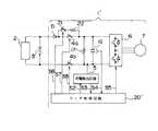
図1は、本発明の一実施例に係る電気自動車用空調装置の電源入力回路を含む空調制御装置の基本構成を示した回路ブロック図である。
【0019】
この空調制御装置1の場合、電気自動車に搭載される空調装置の圧縮機へ供給される高圧直流電源3からの高圧直流電流を交流電源に変換して圧縮機を駆動する駆動装置であるインバータ6と、インバータ6に接続されるコンプレッサモータ7と、高圧直流電源3からの高圧直流電流をインバータ6へ供給する電源入力回路と、高圧直流電源3の負極側のインバータ6入力前段の接続線に接続され、高圧直流電源3及び車体アース間の漏電抵抗の大きさを検出して漏電の有無を判定する漏電検出回路5とを含んでいる。
【0020】
ここでの電源入力回路は、高圧直流電源3側の正極側に接続された逆接続防止用のダイオードDと、高圧直流電源3の正極側及び負極側間に接続されて高圧直流電流からの充電を行うコンデンサ16と、高圧直流電源3の正極側及び負極側間に接続されてコンデンサ16からの放電を行う放電抵抗17と、高圧直流電源3側の負極側に接続されたスイッチング素子Qとから成っている。即ち、この電源入力回路では、図3に示した従来のもののように電流遮断装置や充電用のスイッチを使用しない簡素な構成となっている。
【0021】
又、この空調制御装置1の場合、漏電検出回路5を駆動して漏電検出回路5から得た漏電検出結果や、コンデンサ16の充電状態を検出した結果に応じてスイッチング素子Qの動作制御やインバータ6の駆動制御を行う動作制御回路であるモータ制御回路20を含んでいる。即ち、このモータ制御回路20は、コンデンサ16の充電時に動作制御信号を伝送してスイッチング素子Qを断続的なオン状態でパルス動作させる(このパルス動作は、スイッチング素子Qのスイッチング動作上では充電期間にオン,オフが繰り返される状態を示す)が、具体的にはコンデンサ16の充電電圧を検出し、動作制御信号により充電電圧の大きさに比例させてスイッチング素子Qのパルス動作のパルス幅を可変させる。これにより、パルス幅は充電電圧が小さいときには小さく、大きいときには大きくなる。こうしたスイッチング素子Qのパルス幅を可変させた上でのパルス動作は、できるだけ早くコンデンサ16の充電を完了させると共に、スイッチング素子Qを破損させないために行うものである。仮に、充電始めから大きなパルス幅で充電を行えばスイッチング素子Qが破損される危険を生じ、充電始めから終わりまで小さなパルス幅で充電を行えば充電時間がかかってしまうことになる。尚、スイッチング素子Qとしては、図中ではIGBT仕様としたが、トランジスタやFET等も使用することができる。
【0022】
こうした構成のため、モータ制御回路20と駆動制御や動作制御の対象となる各部との間において、漏電検出回路5との間では駆動信号及び漏電検出信号の授受を行うための信号線S2,S3が接続され、コンデンサ16との間では充電電圧を入力検出するための信号線S4が接続され、インバータ6との間では駆動制御信号を送出するための信号線S5が接続され、スイッチング素子Qとの間では動作制御信号を送出するための信号線S1が接続されており、全体として図3の従来の場合と比べて構成が簡素になっている。
【0023】
尚、ここでの空調制御装置1にも高圧直流電源3から高圧直流電流が供給されるが、高圧直流電源3には走行制御装置2が接続されている。
【0024】
このような空調制御装置1の電源入力回路においてコンデンサ16への充電を行う場合、コンデンサ16の端子間電圧としてインバータ6に印加される直流電圧が充電電圧として信号線S4を介してモータ制御回路20で検出されるため、モータ制御回路20では信号線S1を介して動作制御信号をスイッチング素子Qへ伝送してスイッチング素子Qを断続的にオン状態とし、この断続的なオン状態で動作制御信号により充電電圧の大きさに比例させてパルス幅を可変させた上でスイッチング素子Qをパルス駆動させる。即ち、充電期間では上述したようにスイッチング素子Qのスイッチング動作がオン,オフの繰り返し状態となるが、充電完了時にはスイッチング素子Qを連続的にオン状態としてインバータ6によるコンプレッサモータ7の駆動を行わせるようにする。
【0025】
ところで、こうしたスイッチング素子Qのパルス動作によるコンデンサ16への充電の際、コンデンサ16の充電電圧が小さいとき(充電量が少ないとき)にはダイオードD及びスイッチング素子Qに大きな電流が流れるため、ダイオードDやスイッチング素子Qが破壊されないようにパルス幅を小さくして充電を行わせる。又、コンデンサ16の充電電圧が大きいとき(充電量が多いとき)にはできるだけ早く充電が完了するようにパルス幅を大きくして充電を行わせる。このようなスイッチング素子Qのパルス駆動制御による充電を行えば、デバイスへ負担をかけずに常時安定して迅速に充電できる。
【0026】
尚、放電抵抗17は、例えばメンテナンス時に際してコンデンサ16に電荷が残っている場合等の危険を回避させるためのものである。コンデンサ16の電荷を放電させる場合、モータ制御回路20は信号線S1を介して動作制御信号をスイッチング素子Qへ伝送してスイッチング素子Qをオフ状態とし、このオフ状態で放電抵抗17においてコンデンサ16からの電荷放電が行われる。
【0027】
因みに、空調制御装置1における通常動作の場合、モータ制御回路20はコンデンサ16に所定の電圧が充電された後に信号線S5を介して駆動制御信号によりインバータ6を駆動する。
【0028】
一方、漏電検出回路5により漏電検出する場合、モータ制御回路20は信号線S1を介して動作制御信号をスイッチング素子Qへ伝送してスイッチング素子Qをオフ状態とし、このオフ状態で駆動信号により信号線S2を介して漏電検出回路5を駆動し、漏電検出回路5により漏電検出された結果の漏電検出信号を信号線S3を通して得る。
【0029】
ここでは、漏電検出電流の空調制御装置1側への流入がダイオードD及びスイッチング素子Qにより阻止されるため、空調装置側のみで簡単にして適確に漏電検出が行われることになる。因みに、モータ制御回路20は漏電検出の結果として、漏電が著しい場合にはコンプレッサモータ7を停止させるための駆動制御信号をインバータ6へ送出したり、或いは必要に応じて使用者へのその旨の通報を行う。
【0030】
図2は、上述した空調制御装置1における電源入力回路の構成をそれぞれ変形した比較例の動作性を検証するために示した回路ブロック図で、同図(a)は比較例1に関するもの,同図(b)は比較例2に関するもの,同図(c)は比較例3に関するものである。
【0031】
これらの比較例1〜3の何れの電源入力回路の場合も、コンデンサ16の充電は可能であるが、漏電検出に際しては走行制御装置2側にも漏電検出電流が流れてしまうため、空調装置側のみでの漏電検出を適確に行うことができない。即ち、図2(a)の場合には高圧直流電源3の負極側に接続したダイオードDから漏電検出電流が走行制御装置2側に流れ、図2(b)の場合には高圧直流電源3の負極側から直接漏電検出電流が走行制御装置2側に流れ、図2(c)の場合にはインバータ6又は放電抵抗17を通して高圧直流電源3の正極側から漏電検出電流が走行制御装置2側に流れてしまう。従って、これらの比較例1〜3の電源入力回路は、何れも漏電が走行装置側で発生したのか、空調装置側で発生したのかを区別できないため、機能的に好ましくない。
【0032】
【発明の効果】
以上に述べた通り、本発明の電気自動車用空調装置の電源入力回路によれば、従来の回路で必要とされた電流遮断装置の正極側及び負極側でのスイッチや充電スイッチを不要とし、高圧直流電源の負極側に接続された一個のスイッチング素子を設け、モータ制御回路によりコンデンサの充電時に動作制御信号を伝送してスイッチング素子をオン状態でパルス動作させ、動作制御信号により充電電圧の大きさに比例させてパルス動作のパルス幅を可変させているので、簡素な構成でデバイスへ負担をかけずに常時安定して迅速に充電できるようになる。この結果、早く充電が完了するため、空調装置の運転開始時間も短縮されて車内温度を早く設定温度に到達させられるものとなる。
【0033】
又、この電源入力回路の場合、高圧直流電源の負極側のスイッチング素子以外に高圧直流電源の正極側にダイオードが接続されており、これらのスイッチング素子及びダイオードが漏電検出する場合に漏電検出電流の空調制御装置側への流入を阻止するため、空調装置側のみでの漏電検出が簡単にして適確に行い得るようになる。この結果、最小容量のダイオードでコンデンサの長寿命化を計り得るものとなる。
【図面の簡単な説明】
【図1】本発明の一実施例に係る電気自動車用空調装置の電源入力回路を含む空調制御装置の基本構成を示した回路ブロック図である。
【図2】図1に示す電源入力回路の構成をそれぞれ変形した比較例の動作性を検証するために示した回路ブロック図で、(a)は比較例1に関するもの,(b)は比較例2に関するもの,(c)は比較例3に関するものである。
【図3】従来の電気自動車用空調装置の電源入力回路を含む空調制御装置の基本構成を示した回路ブロック図である。
【符号の説明】
1,1´ 空調制御装置
2 走行制御装置
3 高圧直流電源
4a 正極側電流遮断装置
4b 負極側電流遮断装置
5 漏電検出回路
6 インバータ
7 コンプレッサモータ
16 コンデンサ
17 放電抵抗
20,20´ モータ制御回路
21 充電スイッチ
22 充電抵抗
D ダイオード
Q スイッチング素子
S1〜S8 信号線[0001]
BACKGROUND OF THE INVENTION
The present invention is an electric circuit of an air-conditioning control device that mainly controls an air-conditioning device mounted on an electric vehicle, and supplies the high-voltage DC current from a high-voltage DC power source to a drive device that drives a compressor of the air-conditioning device. The present invention relates to a power input circuit for an air conditioner.
[0002]
[Prior art]
2. Description of the Related Art Conventionally, as an air conditioning control device including a power input circuit of this kind of electric vehicle air conditioner, for example, a configuration as shown in FIG.
[0003]
This air-
[0004]
Here, the power input circuit includes a diode D for preventing reverse connection connected to the positive side of the high-voltage DC power source 3, and charging from the high-voltage DC current connected between the positive side and the negative side of the high-voltage DC power source 3. A
[0005]
Further, in the case of this air
[0006]
Due to such a configuration, the signal line S2 for transmitting / receiving the drive signal and the leakage detection signal to / from the
[0007]
The air
[0008]
When charging the
[0009]
Therefore, instead of such a procedure, the
[0010]
On the other hand, when leakage detection is performed only on the air conditioner side by the
[0011]
[Problems to be solved by the invention]
In the case of the power input circuit for the electric vehicle air conditioner described above, a large-capacity diode must be used to withstand the high-voltage DC current from the high-voltage DC power supply. In addition, there is a problem that the number of parts is reduced because it is necessary to connect and wire the signal line between the charge switch that is controlled to open and close by the motor control circuit and both the positive and negative current interrupting devices. There is a problem that the configuration becomes complicated by increasing the number, and this results in an increase in cost and scale.
[0012]
In addition, the high-voltage DC power supply installed in electric vehicles is normally insulated from the vehicle body, but if the insulation is broken, there is a risk of causing an electric shock. Although a detection circuit is provided and the inverter is driven and controlled by the motor control circuit, when the leakage detection is performed only on the air conditioner side, the circuit on the air conditioner control unit side and the circuit on the travel control unit side must be shut off. Therefore, there is also a situation that at least the negative electrode side in the current interrupting device is indispensable.
[0013]
The present invention has been made to solve such problems, and its technical problem is to provide a power supply for an air conditioner for an electric vehicle that can be stably and quickly charged without burdening the device with a simple configuration. To provide an input circuit.
[0014]
[Means for Solving the Problems]
According to the present invention, a high-voltage DC current from a high-voltage DC power supply is supplied to a drive device that drives a compressor of an air conditioner mounted on an electric vehicle, and the high-voltage DC power supply is connected between the positive electrode side and the negative electrode side. A power input circuit of an air conditioner for an electric vehicle including a capacitor for charging from the high-voltage DC current, a diode connected to the positive electrode side of the high-voltage DC power source, and a switching element connected to the negative electrode side of the high-voltage DC power source. A power input circuit for an air conditioner for an electric vehicle is obtained.
[0015]
According to the present invention, the power input circuit of the air conditioner for an electric vehicle includes an operation control circuit that controls the operation of the switching element in accordance with the result of detecting the charged state of the capacitor. A power input circuit for an air conditioner for an electric vehicle that operates in a pulsed manner by an operation control signal from the operation control circuit during charging is obtained.
[0016]
Furthermore, according to the present invention, in the power input circuit of the air conditioner for an electric vehicle, the operation control circuit detects the charging voltage of the capacitor and performs a pulse operation in proportion to the magnitude of the charging voltage by the operation control signal. A power input circuit for an air conditioner for an electric vehicle that can vary the pulse width of the electric vehicle is obtained.
[0017]
DETAILED DESCRIPTION OF THE INVENTION
The power input circuit of the air conditioner for an electric vehicle according to the present invention will be described in detail with reference to the drawings.
[0018]
FIG. 1 is a circuit block diagram showing a basic configuration of an air conditioning control device including a power input circuit of an air conditioning system for an electric vehicle according to an embodiment of the present invention.
[0019]
In the case of this air
[0020]
Here, the power input circuit includes a diode D for preventing reverse connection connected to the positive side of the high-voltage DC power source 3, and charging from the high-voltage DC current connected between the positive side and the negative side of the high-voltage DC power source 3. A
[0021]
Further, in the case of this air
[0022]
Due to such a configuration, signal lines S2 and S3 for exchanging drive signals and leakage detection signals with the
[0023]
The air
[0024]
When charging the
[0025]
By the way, when the
[0026]
The
[0027]
Incidentally, in the case of normal operation in the air
[0028]
On the other hand, when the leakage detection is performed by the
[0029]
Here, since the inflow of the leakage detection current to the air
[0030]
FIG. 2 is a circuit block diagram shown in order to verify the operability of the comparative example in which the configuration of the power input circuit in the above-described air
[0031]
In any of the power supply input circuits of Comparative Examples 1 to 3, the
[0032]
【The invention's effect】
As described above, according to the power input circuit of the air conditioner for an electric vehicle of the present invention, the switch and the charge switch on the positive electrode side and the negative electrode side of the current interrupt device required in the conventional circuit are unnecessary, and the high voltage One switching element connected to the negative side of the DC power supply is provided, and the motor control circuit transmits an operation control signal when charging the capacitor to pulse the switching element in the ON state, and the magnitude of the charging voltage is determined by the operation control signal. Since the pulse width of the pulse operation is varied in proportion to the above, it is possible to constantly and quickly charge the battery with a simple configuration without imposing a burden on the device. As a result, since the charging is completed quickly, the operation start time of the air conditioner is shortened, and the in-vehicle temperature can quickly reach the set temperature.
[0033]
In the case of this power input circuit, a diode is connected to the positive side of the high-voltage DC power supply in addition to the switching element on the negative side of the high-voltage DC power source. In order to prevent inflow to the air conditioning control device side, the leakage detection only on the air conditioning device side can be performed easily and accurately. As a result, the life of the capacitor can be extended with the diode having the minimum capacity.
[Brief description of the drawings]
FIG. 1 is a circuit block diagram showing a basic configuration of an air conditioning control device including a power input circuit of an air conditioning system for an electric vehicle according to an embodiment of the present invention.
2 is a circuit block diagram for verifying the operability of a comparative example in which the configuration of the power input circuit shown in FIG. 1 is modified, where (a) relates to comparative example 1, and (b) shows a comparative example. (C) relates to Comparative Example 3.
FIG. 3 is a circuit block diagram showing a basic configuration of an air conditioning control device including a power supply input circuit of a conventional electric vehicle air conditioning device.
[Explanation of symbols]
DESCRIPTION OF
Claims (3)
Translated fromJapanesePriority Applications (2)
| Application Number | Priority Date | Filing Date | Title |
|---|---|---|---|
| JP34008397AJP3734236B2 (en) | 1997-12-10 | 1997-12-10 | Electric vehicle air conditioner power supply input circuit |
| US09/207,573US6049185A (en) | 1997-12-10 | 1998-12-08 | Power circuit of an air conditioner for electric vehicles |
Applications Claiming Priority (1)
| Application Number | Priority Date | Filing Date | Title |
|---|---|---|---|
| JP34008397AJP3734236B2 (en) | 1997-12-10 | 1997-12-10 | Electric vehicle air conditioner power supply input circuit |
Publications (2)
| Publication Number | Publication Date |
|---|---|
| JPH11178101A JPH11178101A (en) | 1999-07-02 |
| JP3734236B2true JP3734236B2 (en) | 2006-01-11 |
Family
ID=18333562
Family Applications (1)
| Application Number | Title | Priority Date | Filing Date |
|---|---|---|---|
| JP34008397AExpired - Fee RelatedJP3734236B2 (en) | 1997-12-10 | 1997-12-10 | Electric vehicle air conditioner power supply input circuit |
Country Status (2)
| Country | Link |
|---|---|
| US (1) | US6049185A (en) |
| JP (1) | JP3734236B2 (en) |
Families Citing this family (30)
| Publication number | Priority date | Publication date | Assignee | Title |
|---|---|---|---|---|
| EP0812049A4 (en)* | 1995-02-21 | 2000-06-07 | Hitachi Ltd | APPARATUS AND METHOD FOR PROVIDING ELECTRICITY TO A VEHICLE, SEMICONDUCTOR CIRCUIT DEVICE FOR USE IN SAID APPARATUS AND WIRING DEVICE FOR A MOTOR VEHICLE OR OTHER VEHICLE |
| JP2001165056A (en)* | 1999-12-13 | 2001-06-19 | Matsushita Electric Ind Co Ltd | Drive device for electric compressor |
| US6304056B1 (en) | 2000-09-21 | 2001-10-16 | Ford Global Technologies, Inc. | Pulsed charge power delivery circuit for a vehicle having a combined starter/alternator |
| US6580178B1 (en) | 2000-09-21 | 2003-06-17 | Ford Global Technologies, Inc. | Pulsed charge starter/alternator control system |
| US6420793B1 (en) | 2000-09-21 | 2002-07-16 | Ford Global Technologies, Inc. | Power delivery circuit with boost for energetic starting in a pulsed charge starter/alternator system |
| JP3644409B2 (en)* | 2001-06-06 | 2005-04-27 | 松下電器産業株式会社 | Automotive air conditioner |
| JP2002369584A (en)* | 2001-06-06 | 2002-12-20 | Sanden Corp | Drive apparatus of motor-driven compressor for automotive air conditioner |
| JP4418259B2 (en)* | 2004-02-27 | 2010-02-17 | 株式会社日立製作所 | Electric brake device |
| DE602005020085D1 (en)* | 2004-05-17 | 2010-05-06 | Sanyo Electric Co | Inverter with a detection of fusion of the relay contacts |
| JP4760000B2 (en)* | 2004-12-09 | 2011-08-31 | ダイキン工業株式会社 | Multiphase current supply circuit, driving device, compressor, and air conditioner |
| JP4635710B2 (en)* | 2005-05-11 | 2011-02-23 | トヨタ自動車株式会社 | AC voltage output device |
| TWI271328B (en)* | 2005-12-27 | 2007-01-21 | Memetics Technology Co Ltd | Air conditioning system having self-sustained power supply apparatus for engine-driven transportation tools |
| KR101045903B1 (en)* | 2006-01-27 | 2011-07-01 | 메메틱스 테크놀로지 컴퍼니 리미티드 | Transportation air conditioning system using engine with its own power supply |
| FR2900241B1 (en)* | 2006-04-21 | 2008-07-11 | Alstom Transport Sa | METHOD FOR SCREENING A RESISTIVE SHORT CIRCUIT, SYSTEM, MODULE, AND RECORDING MEDIUM FOR THIS METHOD |
| CN100380768C (en)* | 2006-07-25 | 2008-04-09 | 株洲时代广创变流技术有限公司 | Locomotive air conditioner electric power controlling method and apparatus |
| FR2928058B1 (en)* | 2008-02-21 | 2010-02-19 | Schneider Toshiba Inverter | SPEED DRIVE INCLUDING A DEVICE FOR PROTECTION AGAINST OVERCURRENTS AND OVERVOLTAGES. |
| JP4839357B2 (en)* | 2008-09-02 | 2011-12-21 | 本田技研工業株式会社 | Fuel cell vehicle |
| US8558492B2 (en)* | 2009-11-13 | 2013-10-15 | Lg Electronics Inc. | Apparatus for driving motor of electric vehicle |
| JP6027366B2 (en)* | 2012-07-31 | 2016-11-16 | マツダ株式会社 | Discharge device for power storage device |
| JP5987532B2 (en)* | 2012-07-31 | 2016-09-07 | マツダ株式会社 | Discharge device for power storage device |
| JP5742814B2 (en)* | 2012-10-17 | 2015-07-01 | トヨタ自動車株式会社 | Vehicle power supply |
| CN103884950B (en)* | 2012-12-20 | 2016-12-28 | 东莞钜威动力技术有限公司 | The current leakage detection system of a kind of energy-accumulating power station and electrical leakage detecting method |
| JP5953240B2 (en)* | 2013-01-25 | 2016-07-20 | カルソニックカンセイ株式会社 | Motor control device and electric compressor |
| CN103192679A (en)* | 2013-04-03 | 2013-07-10 | 苏州高创特新能源发展有限公司 | Solar photovoltaic power generation automotive air conditioner device |
| KR101951675B1 (en)* | 2017-03-28 | 2019-02-25 | 엘지전자 주식회사 | Air conditioner having power saving function |
| JP2019213271A (en)* | 2018-05-31 | 2019-12-12 | サンデン・オートモーティブコンポーネント株式会社 | Discharge control device |
| JP7518333B2 (en)* | 2020-01-20 | 2024-07-18 | 株式会社今仙電機製作所 | Vehicle power supply device |
| JP7506300B2 (en)* | 2020-03-13 | 2024-06-26 | 株式会社今仙電機製作所 | Vehicle power supply device |
| JP7568908B2 (en)* | 2020-11-02 | 2024-10-17 | 株式会社今仙電機製作所 | Vehicle power supply device |
| JP7380543B2 (en)* | 2020-12-24 | 2023-11-15 | 株式会社豊田自動織機 | In-vehicle inverter equipment and in-vehicle fluid machinery |
Family Cites Families (14)
| Publication number | Priority date | Publication date | Assignee | Title |
|---|---|---|---|---|
| US4326386A (en)* | 1979-09-18 | 1982-04-27 | Sankyo Electric Company Limited | Temperature control circuit for automobile air-conditioning system |
| JPS5863082A (en)* | 1981-10-09 | 1983-04-14 | Fanuc Ltd | Inverter circuit |
| JPS58145519A (en)* | 1982-02-20 | 1983-08-30 | Sanden Corp | Controller for cooler of vehicle |
| FR2613554B1 (en)* | 1987-03-30 | 1993-05-07 | Telemecanique Electrique | PULSE WIDTH MODULATION CONVERTER |
| US4879639A (en)* | 1987-05-11 | 1989-11-07 | Fuji Electric Co., Ltd. | Power converter for driving an AC motor at a variable speed |
| US5127085A (en)* | 1991-04-01 | 1992-06-30 | General Motors Corporation | Ride-through protection circuit for a voltage source inverter traction motor drive |
| JPH062901A (en)* | 1992-06-23 | 1994-01-11 | Matsushita Seiko Co Ltd | Controller for ventilation fan |
| JPH0632141A (en)* | 1992-07-20 | 1994-02-08 | Matsushita Electric Ind Co Ltd | Rush preventive circuit for electric automobile air conditioner |
| JPH07147767A (en)* | 1993-11-22 | 1995-06-06 | Sanden Corp | Power controller motor driver |
| JPH07241002A (en)* | 1994-02-24 | 1995-09-12 | Toyota Motor Corp | Leakage detection device for electric vehicles |
| JP3290031B2 (en)* | 1994-07-06 | 2002-06-10 | サンデン株式会社 | Vehicle air conditioner |
| JPH09201066A (en)* | 1996-01-16 | 1997-07-31 | Sanden Corp | Inverter protective device |
| JP3746334B2 (en)* | 1996-08-22 | 2006-02-15 | トヨタ自動車株式会社 | Permanent magnet type synchronous motor drive control apparatus and method |
| JP3736933B2 (en)* | 1997-04-23 | 2006-01-18 | 本田技研工業株式会社 | Electric vehicle control device |
- 1997
- 1997-12-10JPJP34008397Apatent/JP3734236B2/ennot_activeExpired - Fee Related
- 1998
- 1998-12-08USUS09/207,573patent/US6049185A/ennot_activeExpired - Lifetime
Also Published As
| Publication number | Publication date |
|---|---|
| JPH11178101A (en) | 1999-07-02 |
| US6049185A (en) | 2000-04-11 |
Similar Documents
| Publication | Publication Date | Title |
|---|---|---|
| JP3734236B2 (en) | Electric vehicle air conditioner power supply input circuit | |
| JP3729228B2 (en) | Electric leakage prevention control device for air conditioner for electric vehicle | |
| CN102047368B (en) | Relay controller | |
| EP3300237B1 (en) | Power supply control device and power supply control method | |
| JP4595248B2 (en) | Automotive air conditioner | |
| US7443643B2 (en) | Inverter device for automobile | |
| KR940006839A (en) | Brake Control of Electric Motor Vehicles | |
| JPH11205909A (en) | Charging device for electric vehicles | |
| JP2001165056A (en) | Drive device for electric compressor | |
| CN113039714B (en) | Control device for high-voltage equipment | |
| KR20180068370A (en) | Pre-charge method and system for high voltage link capacitor of vehicle | |
| KR20200045836A (en) | System of determining state of power relay assembly | |
| JP2018098959A (en) | On-vehicle unit | |
| US5600227A (en) | Electrical storage battery charger and conditioner | |
| JP3196416B2 (en) | Automotive air conditioners | |
| JP3152126B2 (en) | Automotive air conditioners | |
| JP3678165B2 (en) | Automotive air conditioner | |
| US20050198982A1 (en) | Vehicle air conditioniner | |
| EP1610453B1 (en) | Inverter device | |
| CN100481688C (en) | Inverter device | |
| JP6344334B2 (en) | Power control unit | |
| JP3640682B2 (en) | Battery connection control device for electric vehicle | |
| JP3047696B2 (en) | Air conditioner | |
| JP3166453B2 (en) | Automotive air conditioners | |
| JP3705278B2 (en) | Battery connection control device for electric vehicle |
Legal Events
| Date | Code | Title | Description |
|---|---|---|---|
| A621 | Written request for application examination | Free format text:JAPANESE INTERMEDIATE CODE: A621 Effective date:20040728 | |
| A977 | Report on retrieval | Free format text:JAPANESE INTERMEDIATE CODE: A971007 Effective date:20050913 | |
| TRDD | Decision of grant or rejection written | ||
| A01 | Written decision to grant a patent or to grant a registration (utility model) | Free format text:JAPANESE INTERMEDIATE CODE: A01 Effective date:20050928 | |
| A61 | First payment of annual fees (during grant procedure) | Free format text:JAPANESE INTERMEDIATE CODE: A61 Effective date:20051017 | |
| R150 | Certificate of patent or registration of utility model | Free format text:JAPANESE INTERMEDIATE CODE: R150 | |
| FPAY | Renewal fee payment (event date is renewal date of database) | Free format text:PAYMENT UNTIL: 20081028 Year of fee payment:3 | |
| FPAY | Renewal fee payment (event date is renewal date of database) | Free format text:PAYMENT UNTIL: 20091028 Year of fee payment:4 | |
| FPAY | Renewal fee payment (event date is renewal date of database) | Free format text:PAYMENT UNTIL: 20101028 Year of fee payment:5 | |
| FPAY | Renewal fee payment (event date is renewal date of database) | Free format text:PAYMENT UNTIL: 20101028 Year of fee payment:5 | |
| FPAY | Renewal fee payment (event date is renewal date of database) | Free format text:PAYMENT UNTIL: 20111028 Year of fee payment:6 | |
| FPAY | Renewal fee payment (event date is renewal date of database) | Free format text:PAYMENT UNTIL: 20121028 Year of fee payment:7 | |
| FPAY | Renewal fee payment (event date is renewal date of database) | Free format text:PAYMENT UNTIL: 20121028 Year of fee payment:7 | |
| FPAY | Renewal fee payment (event date is renewal date of database) | Free format text:PAYMENT UNTIL: 20131028 Year of fee payment:8 | |
| R250 | Receipt of annual fees | Free format text:JAPANESE INTERMEDIATE CODE: R250 | |
| S533 | Written request for registration of change of name | Free format text:JAPANESE INTERMEDIATE CODE: R313533 | |
| R350 | Written notification of registration of transfer | Free format text:JAPANESE INTERMEDIATE CODE: R350 | |
| R250 | Receipt of annual fees | Free format text:JAPANESE INTERMEDIATE CODE: R250 | |
| R250 | Receipt of annual fees | Free format text:JAPANESE INTERMEDIATE CODE: R250 | |
| LAPS | Cancellation because of no payment of annual fees |