JP3733359B2 - Disparity estimation method, image transmission method, image display method, multi-view image transmission method, multi-view image restoration method, and disparity estimation apparatus - Google Patents
Disparity estimation method, image transmission method, image display method, multi-view image transmission method, multi-view image restoration method, and disparity estimation apparatusDownload PDFInfo
- Publication number
- JP3733359B2 JP3733359B2JP2003154401AJP2003154401AJP3733359B2JP 3733359 B2JP3733359 B2JP 3733359B2JP 2003154401 AJP2003154401 AJP 2003154401AJP 2003154401 AJP2003154401 AJP 2003154401AJP 3733359 B2JP3733359 B2JP 3733359B2
- Authority
- JP
- Japan
- Prior art keywords
- parallax
- image
- initial
- estimation
- evaluation value
- Prior art date
- Legal status (The legal status is an assumption and is not a legal conclusion. Google has not performed a legal analysis and makes no representation as to the accuracy of the status listed.)
- Expired - Fee Related
Links
Images


Landscapes
- Processing Or Creating Images (AREA)
- Image Processing (AREA)
- Testing, Inspecting, Measuring Of Stereoscopic Televisions And Televisions (AREA)
- Compression Or Coding Systems Of Tv Signals (AREA)
- Image Analysis (AREA)
Description
Translated fromJapanese【0001】
【発明の属する技術分野】
本発明は、多視点画像の伝送方法及び多視点画像の表示方法に関する。また、本発明は、多視点画像の中間視点画像生成方法及び視差推定方法及びその装置に関するものである。
【0002】
【従来の技術】
従来、立体映像方式には様々なものが提案されているが、特殊な眼鏡をかけることなく立体動画像を複数人数で観察できる方式として、多視点画像による多眼式立体映像方式が有望である。多眼式立体映像方式においては、使用するカメラ台数及び表示装置台数が多いほど、観察者に対して自然な運動視差を感じさせることができ、また、多人数での観察が容易になる。しかしながら、撮像系の規模やカメラの光軸の設定等の制約により、実用的に用いることができるカメラ台数には限度がある。また、伝送、蓄積過程においては、カメラ台数に比例して増大する情報量を低減することが望まれる。
【0003】
そこで、表示側において、2眼式ステレオ画像から中間視点画像を生成することにより多眼式立体画像を表示できれば、撮像系の負担を軽減し、伝送、蓄積時の情報量を低減することができることになる。視点の異なる複数の画像から、その異なる視点間の任意の視点で見えるべき中間視点画像を生成するためには、画像間で画素の対応を求めて奥行きを推定する必要がある。
【0004】
また、動画像をデジタル伝送するための画像圧縮方式として、MPEG−1、MPEG−2が提案されている。さらに、MPEG−2を拡張して多視点画像を伝送する試みも行われている(ISO/IEC13818-2/PDAM3)。図28は、MPEG−2シンタックスの概略図である。MPEG−2による伝送は、Sequence、GOP(Group Of Picture)、Picture という階層構造を持つ画像データの符号化、復号化によって行われる。ISO/IEC13818-2/PDAM3によると、MPEG−2の拡張による多視点画像の伝送は、(明記されていないためはっきりしないが)GOP層を拡張して実現されるようである。
【0005】
図29は、伝送される多視点画像の時空間方向の関係を示すものである。従来のMPEG−2で用いられてきた動き補償に加えて、視差補償を用いることによって符号化効率を高めようとしている。多視点画像を伝送する際には、各カメラに関する情報(カメラの位置、カメラの光軸の向き等のカメラパラメータ)を付加して伝送する必要がある。ISO/IEC13818-2/PDAM3には、カメラパラメータは図28のPic.Extension(Picture層の拡張)に含めて伝送することが述べられているが、具体的なカメラパラメータの記述については述べられていない。
【0006】
カメラパラメータの記述に関しては、CG言語であるOpenGLにおいて、カメラの位置、カメラの光軸の向き、カメラの位置と画像面との距離がカメラパラメータとして定義されている(「オープン ジーエル プログラミングガイド」(OpenGL Programming Guide,The Official Guide to Learning OpenGL,Release 1,Addison-Wesley Publishing Company,1993))。
【0007】
図30は、OpenGLによるカメラパラメータの定義を示す説明図である。図30において、Aはレンズ中心、Bは画像面(すなわち撮像面)の中心、CはBから画像上端におろした垂線と画像上端の交点を示す。A,B,Cの座標値はそれぞれ、
(opticalcenterX,opticalcenterY,opticalcenterZ),(imageplanecenterX,imageplanecenterY,imageplanecenterZ),(imageplaneverticalX,imageplaneverticalY,imageplaneverticalZ)として定義されている。
【0008】
上記のOpenGLで定義されるカメラパラメータの情報をPic.Extensionに付加して多視点画像を伝送することが容易に考えられる。
【0009】
【発明が解決しようとする課題】
しかしながら上記のような従来の方法では、中間視点画像生成のための画像間の対応づけにおける根本的な問題は、奥行きが不連続に変化する物体輪郭線において、オクルージョンが生じるために画像間の対応を精度よく求めるのは困難なことである。しかし、この物体輪郭線近傍での視差の推定値は、生成される中間視点画像における物体の輪郭位置を決定するため、中間視点画像の合成時には非常に重要である。すなわち、視差推定時に物体輪郭線近傍で視差の推定誤差が生じると、前景領域の画素が背景側にはりついたり、逆に背景領域の画素が前景にはりつき、物体の輪郭線が乱れたり、物体輪郭線近傍の背景領域に偽輪郭が生じることになる。
【0010】
本発明はかかる点に鑑み、物体輪郭線近傍での視差の急激な変化(不連続な変化)を精度よく推定する視差推定方法およびその装置を提供することを目的とする。
【0011】
【課題を解決するための手段】
第1の本発明(請求項1対応)は、2つの撮像画像の初期視差と前記初期視差の信頼性評価値とを計算し、前記信頼性評価値と前記画像のエッジ検出結果とを用いて視差が不連続に変化する物体輪郭線を抽出し、前記信頼性評価値に基づき、前記物体輪郭線を含む前記初期視差の信頼性の低い領域を抽出し、その抽出した初期視差の信頼性の低い領域における視差は、前記信頼性の低い領域の周囲の視差に対して滑らかに接続するように、かつ、前記物体輪郭線においては変化するように決定し、前記物体輪郭線において不連続に変化する視差推定を行うことを特徴とする視差推定方法である。
また、第2の本発明(請求項2対応)は、初期視差の信頼性の低い領域における視差は、前記視差と、前記物体輪郭線とを用いて定義した視差分布のエネルギーを最小化するように決定することを特徴とする第1の本発明の視差推定方法である。
また、第3の本発明(請求項3対応)は、前記エッジ検出は、周波数特性の異なる方向別フィルタの各出力を統合して行うことを特徴とする第1又は第2の本発明の視差推定方法である。
また、第4の本発明(請求項4対応)は、前記エッジ検出は、前記周波数特性の異なる方向別フィルタの各出力の統合結果に対して、更に稜線抽出を行うことを特徴とする第3の本発明の視差推定方法である。
また、第5の本発明(請求項5対応)は、前記初期視差の信頼性評価値は、初期視差計算時の残差平方和を用いることを特徴とする第1〜第4のいずれか本発明の視差推定方法である。
また、第6の本発明(請求項6対応)は、前記初期視差の信頼性評価値は、初期視差計算時の1画素当たりの残差平方和を用いることを特徴とする第1〜第4のいずれか本発明の視差推定方法である。
また、第7の本発明(請求項7対応)は、前記初期視差の信頼性評価値は、初期視差計算時の残差平方和、画像のノイズレベル、及び輝度勾配を用いて計算することを特徴とする第1〜第4のいずれか本発明の視差推定方法である。
また、第8の本発明(請求項8対応)は、前記初期視差の信頼性評価値は、左右双方の画像を基準として計算した初期視差の対応の差異を用いて計算することを特徴とする第1〜第4のいずれか本発明の視差推定方法である。
また、第9の本発明(請求項9対応)は、前記初期視差の信頼性評価値は、第5〜第8のいずれか本発明の前記視差推定方法の2つ以上を組み合わせて計算することを特徴とする視差推定方法である。
また、第10の本発明(請求項10対応)は、2眼式画像から左右それぞれの画像を基準とした初期視差と前記初期視差の信頼性評価値を計算し、初期視差が正しく計算できない領域での視差は請求項1〜9のいずれかに記載の方法によって再計算し、前記2眼式画像の一方の画像と当該一方の画像を基準とした前記再計算後の視差から前記2眼式画像の他方の画像を予測して予測誤差を計算し、前記一方の画像を基準とした視差から他方の画像を基準とした前記再計算後の視差を予測して予測誤差を計算し、前記2眼式画像の一方の画像と当該一方の画像を基準とした前記再計算後の視差と前記2眼式画像の他方の画像の予測誤差と前記他方の画像を基準とした再計算後の視差の予測誤差とを符号化し伝送する画像伝送方法である。
また、第11の本発明(請求項11対応)は、第10の本発明の画像伝送方法により伝送された符号化信号を受信し、その受信信号から2眼式画像及び再計算後の視差を復号化し、その復号化された2眼式画像及び復号化された再計算後の視差を用いて中間視点画像を生成し、その中間視点画像及び前記2眼式画像を併せて多眼式画像として表示する画像表示方法である。
また、第12の本発明(請求項12対応)は、多眼式画像から代表画像を選択し、選択されなかった画像は、2枚の代表画像をそれぞれ基準画像として、2つの撮像画像の初期視差と前記初期視差の信頼性評価値とを計算し、前記信頼性評価値と前記画像のエッジ検出結果とを用いて視差が不連続に変化する物体輪郭線を抽出し、前記信頼性評価値に基づき前記初期視差の信頼性の低い領域を抽出し、その抽出した初期視差の信頼性の低い領域における視差は、周囲の視差に対して滑らかに接続するように、かつ、前記物体輪郭線においては変化するように決定することにより、前記物体輪郭線において不連続に変化する視差推定を行う視差推定方法によって計算した視差と前記2枚の代表画像とを用いて予測し、前記選択されなかった画像と予測画像の残差を計算し、前記代表画像と前記選択されなかった画像の予測誤差を符号化して伝送することを特徴とする多視点画像伝送方法である。
また、第13の本発明(請求項13対応)は、第12の本発明の画像伝送方法により伝送された符号化信号を受信し、前記代表画像を復号化し、前記代表画像をそれぞれ基準画像として第1〜第4のいずれかの本発明の方法によって視差を計算し、送信部で代表画像に選択されなかった画像を前記代表画像と前記視差を用いて予測し、前記選択されなかった画像の予測誤差を復号化し、前記予測誤差を前記予測画像に重畳して多視点画像を復元することを特徴とする多視点画像復元方法である。
また、第14の本発明(請求項14対応)は、前記代表画像の符号化は、1枚の代表画像と当該代表画像を基準として他の代表画像について計算した視差から他の代表画像を予測し、前記一枚の代表画像と前記他の代表画像の予測誤差を符号化することにより行うことを特徴とする第12の本発明の多視点画像伝送方法である。
また、第15の本発明(請求項15対応)は、2つの撮像画像の初期視差を計算する初期視差推定部と、前記初期視差の信頼性評価値と計算する信頼性評価部と、前記画像のエッジを検出する輪郭検出部と、前記信頼性評価値と前記画像のエッジ検出結果とを用いて視差が不連続に変化する物体輪郭線を抽出し、前記信頼性評価値に基づき、前記物体輪郭線を含む前記初期視差の信頼性の低い領域を抽出し、その抽出した初期視差の信頼性の低い領域における視差は、前記信頼性の低い領域の周囲の視差に対して滑らかに接続するように、かつ、前記物体輪郭線においては変化するように決定し、前記物体輪郭線において不連続に変化する視差推定を行う視差推定部を備えたことを特徴とする視差推定装置である。
【0012】
【発明の実施の形態】
以下に、本発明をその実施の形態を示す図面に基づいて説明する。
(第1の実施の形態)
図4は、本発明の第1の実施の形態における画像伝送方法で定義するパラメータを示す図である。図4において、A1,A2はカメラのレンズ中心の位置を示し、B1,B2は撮像面の中心を示す(説明を簡単にするために、撮像面をレンズ中心に対して被写体側に折り返して考えている)。
【0013】
OpenGLでは図4のA1B1,A2B2の距離をカメラのレンズの焦点距離として定義しているが、本発明においては、カメラのレンズ中心と撮像面の距離を該レンズの焦点距離とは独立に定義する。この定義により、合焦時のレンズ中心と撮像面との距離を被写体の距離に応じて計算でき、正確な視野角を計算できる。視野角は、撮像面のサイズと、レンズ中心と撮像面との距離から計算できる。
【0014】
以下に図2を用いて、合焦時のレンズ中心と撮像面との距離が、被写体とレンズ中心との距離によって変化することを説明する。図2は、被写体の位置、合焦時の撮像面の位置と焦点距離の関係を示す図である。図2において、Aは被写体の位置、BはAからの光が結像する点、Oはレンズの中心、Fは平行光がレンズにより結像する点、aは被写体とレンズ中心Oとの距離、bはAからの光が結像する点Bとレンズ中心Oとの距離、fはレンズの焦点距離を示す。a,b,fの間には(数1)の関係が成り立つことが知られている。
【0015】
【数1】
(数1)より、被写体が焦点距離を無視できるくらいレンズから遠い(a>>f)場合には、1/a → 0となりb = fと近似できる。しかし、被写体が比較的レンズに近い場合には、1/aの項を無視できず、b≠fとなる。従って、被写体が比較的レンズに近い場合にも正しく視野角を計算するためには、レンズ中心と結像面との距離を焦点距離とは独立に定義する必要がある。そして、撮像面の幅をwin、高さをhinとすると、撮像時の視野角は(数2)で表される。
【0017】
【数2】
よって、表示時の画像の幅をwout、高さをhoutとすると、撮像時の視野角を再現する観察距離は、
【0019】
【数3】
となる。
【0021】
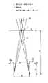
次に、画像内の最近点、最遠点に基づく表示側における見やすさの改善について説明する。図3は、2つのプロジェクタを用いて輻輳投影をする場合の輻輳距離、最近点、最遠点の位置関係を説明するための図である。図3において、Cは輻輳点、Aは最近点、Bは最遠点を示す。
【0022】
輻輳のある投射においては、観察者が輻輳点Cを見る場合に視差が0となる(図3において、両眼とも画像の中心を見ることになるので、左右の目が見る画像内の相対的な位置の違いはなくなる)。そして、最近点Aを見る場合にはいわゆる寄り目の状態となり、画像上で寄り目の方向にDaの視差が生じる。図3において観察者は、輻輳点Cを見るときと比べて、両目とも内側にDa/2ずれた点を見る。また、逆に最遠点Bを見る場合にはいわゆる離れ目の状態となり、画像上で離れ目の方向にDbの視差が生じる。
【0023】
また、図1は平行投影の場合の最近点、最遠点、観察者の輻輳と調節が一致する点の位置関係を示す図である。図1において、Aは表示される画像の最近点、Bは最遠点、Cは観察者の輻輳と調節が一致する点を示す。図1に示す平行投影の場合、Dc の視差がある画像を表示すると、スクリーン上では同じ点に表示され、観察者の輻輳と調節が一致する。
【0024】
上述の図3と図1の画像内における視差は、観察者にスクリーン面(Cを含む面)に対して手前か奥かという立体感として知覚されるが、視差が大きくなると融合しなくなったり(2重に見える状態)、観察者に違和感・不快感を与えたりする。
【0025】
観察者の見やすさの改善は、最近点、最遠点、撮像時の輻輳点をもとに、画像を図3に示す方向(画像1、画像2を各々の投射軸の垂直面内で水平方向)にずらすことにより、輻輳点と最遠距離、最近距離との位置関係を変化させることで可能となる。画像のずらし方については、例えば画像間の視差の平均値を相殺するようにずらすことによって、画像全体を均一に見やすくできる。
【0026】
図5は、そのような処理のブロック図である。図5では、簡単のために2眼式(2視点)のデータについての例を示している。図5において、1は画像復号手段、2は視差推定手段、3は平均視差演算手段、4a,4bは画像シフト手段、5a,5bは画像表示手段である。以下に各手段の動作について説明する。
【0027】
画像復号手段1は、送信側で符号化された多視点画像データを受信し、これを復号する。画像復号手段1により復号された左右の画像は視差推定手段2に送られる。視差推定手段2は、画像復号手段1によって復号された左右の画像から各画素における視差(視差地図)を計算する。例えば、左画像を基準としてブロックマッチングにより視差を計算する場合について、図6を用いて以下に説明する。まず、左画像中に窓領域を設定する。次に、(数4)に示す残差平方和(SSD)を計算する。
【0028】
【数4】
(数4)の計算は、dminからdmaxの範囲のdについて1画素間隔で計算する。そして、dminからdmaxの範囲でSSDを最小にするdの値を、設定した窓領域での視差とする。画像の各画素における視差は、窓領域を順次ずらして設定し、上記の計算をすることによって得られる。
【0030】
SSDを計算する範囲dmin、dmaxは、最近点、最遠点の情報より計算できる。図7、図8を用いて、平行撮影時と輻輳撮影時の場合のdmin、dmaxの求め方について以下に説明する。
【0031】
図7は、平行撮影の場合を示す図である。図7に示す座標系において、左右のレンズ中心の座標値を(−D/2,0)、(D/2,0)、撮像面とレンズ中心との距離をb、3次元空間中の物体位置の水平座標値をX0 、奥行き方向の座標値をZ0 、左右の撮像面で位置(X0、Z0)の物体からの光が撮像される水平位置をそれぞれxl0, xr0とする(xl0, xr0はカメラの光軸と撮像面の交点を原点とする平面座標系の水平座標)と、図形的な関係より、
【0032】
【数5】
となる。よって、左右の画像を基準とした視差はそれぞれ、(数6)に示す式で表される。
【0034】
【数6】
ここで、画像中の最近点の奥行き値をZmin、最遠点の奥行き値をZmaxとすると、SSDを計算する範囲の上限dmaxと下限dminは(数7)で表される。
【0036】
【数7】
また、図8は輻輳撮影の場合を示す図である。図8に示す座標系において、輻輳点(左右のカメラの光軸の交点)の座標値を(0,C)、左右のレンズ中心の座標値を(−D/2,0)、(D/2,0)、撮像面とレンズ中心との距離をb、3次元空間中の物体位置の水平座標値をX0、奥行き方向の座標値をZ0、左右の撮像面で位置(X0、Z0)の物体からの光が撮像される水平位置をそれぞれxl0,xr0とする(xl0,xr0はカメラの光軸と撮像面の交点を原点とする平面座標系の水平座標)と、図形的な関係より、
【0038】
【数8】
となる。したがって、左右の画像を基準とした時の視差はそれぞれ、(数9)に示す式で表される。
【0040】
【数9】
(数9)の式中にX0が残っていることから、輻輳撮像では奥行きが同じであっても、水平方向の位置によって視差が異なる(即ち、再生される立体像が歪む)ことがわかる。今、簡単のためにX0=0(即ちZ軸)上の点における視差を考えると、(数9)にX0=0を代入して(数10)を得る。
【0042】
【数10】
(数10)より、画像中の最近点の奥行き値Zmin、最遠点の奥行き値Zmax、輻輳点の奥行き値Cの位置関係と、水平画素数nx、撮像面(CCD)の幅winから視差の上限画素数dmax、下限画素数dminを決定できる。
【0044】
Z軸上以外の点における視差を考慮する場合には、(数9)の最大値、最小値を計算することによって、視差の上限dmax、下限dminを決定できる。
【0045】
以上説明したように、画像中の最近点の奥行き値、最遠点の奥行き値、カメラの位置、カメラの光軸の向きが与えられると、視差の取るべき値の範囲を計算でき、視差演算時にSSDを計算する範囲を決定できる。平均視差演算手段3は、視差推定手段2によって計算された視差地図の平均を演算する。視差地図の平均は(数11)を計算することによって得られる。
【0046】
【数11】
画像シフト手段4a、4bは、平均視差演算手段3によって得られる平均視差を有する奥行きの点が、表示面と同じ奥行き(すなわち表示面上で視差0となるように)に表示されるように画像をシフトする。
【0048】
平行投影による表示を示す図1において、Aは表示する画像中の最近点の奥行き、Bは最遠点の奥行き、Cは平均視差の奥行きを示す。図1から、平行投影では左右の画像間で(数12)で示すDc の視差がある場合に、スクリーン上で視差がなくなり、輻輳と調節が一致した自然な表示となることがわかる。
【0049】
【数12】
画像シフト手段4aは、(数13)に示すシフト量(右方向へのシフトを正としている)だけ左画像をシフトする。
【0051】
【数13】
そして、画像シフト手段4bは、逆方向に同じ量だけ右画像をシフトする。画像シフト手段4aおよび4bによるシフトの結果、平均視差を有する点がスクリーンと同一の奥行きに表示されるようになる。
【0053】
また、輻輳投影による表示を示す図3において、Aは表示する画像中の最近点の奥行き、Bは最遠点の奥行き、Cは平均視差の奥行きを示す。輻輳投影では、画像の中心で視差が0の場合に、スクリーンと同一の奥行きに表示されることになる。したがって、輻輳投影の場合画像シフト手段4aおよび4bは平均視差を−1/2倍した値だけ左右の画像をシフトする。
【0054】
以上のように本実施の形態によれば、多視点画像を伝送する際に、画像内の最近点、最遠点の情報を付加することにより、表示側で目の疲れない表示(視差制御)を行うことができる。
【0055】
また、カメラの撮像面(CCD)のサイズ、撮像面とレンズ中心との距離、及びレンズの焦点距離に関する情報を付加して伝送することにより、撮影時の視野角に応じた表示を行おうとする際、被写体に接近して撮影した映像についても、表示側で撮影時の視野角を精度よく計算することができる。
【0056】
なお、多視点画像中の最近点、最遠点に関する情報を付加せずに伝送する場合には、最近点、最遠点に関する情報の変わりに、最近点、最遠点に関する情報が付加されていないことを示す専用の符号を付加して伝送し、表示側において、予め設定した範囲内で視差の計算を行うことにより、画像内の最近点、最遠点での視差を推定することができ、本発明に含まれる。
【0057】
さらに、伝送側において、多視点画像中の最近点、最遠点に関する情報を特定の奥行き値に設定することにより、その設定された特定の奥行き範囲での視差が融合範囲に入るように視差制御することができ、本発明に含まれる。
【0058】
また、本発明においては視差の計算を表示側で行う例について説明したが、符号化された画像中に含まれる視差を用いてもよく、本発明に含まれる。図10を用いてそのような例について説明する。
【0059】
図10において、画像復号手段6以外の構成の動作は、図5に示す視差制御方式と同一であるので説明を省略し、以下画像復号手段6の動作について説明する。画像復号手段6は、符号化された画像データを復号し、左右の画像と左画像を基準とした視差を出力する。MPEG−2による多視点画像伝送方式で2眼式画像を伝送する際には、左画像を基準とする視差補償により圧縮率を高めている。符合化された画像データ中から視差を取り出すことにより、表示側で視差の計算をする必要がなくなり、表示側での演算量を低減できる。
【0060】
なお、平均視差演算手段3による視差の平均の計算は、画面の中央部を重視して(数14)による重み付け平均値を用いてもよい。こうのようにすれば、画像の中心部で、より融合しやすい視差制御を行え、本発明に含まれる。
【0061】
【数14】
図9(a)(b)(c)は、(数14)による重み付け平均の計算に用いる重みの分布の例を示す。簡単のため1次元的に示しているが、実際には、画像中央部で周辺部よりも大きな値となる2次元的な分布である。また、重みの値はすべて0以上の値(負でない値)である。
(第2の実施の形態)
図11は、本発明の第2の実施の形態における視差制御方式のブロック図である。図11において、頻度計算手段7、シフト量演算手段8以外の構成は、第1の実施の形態におけるものと同一の動作を行うものであるため、第1の実施の形態での説明図と同一の符号を付し、説明を省略する。以下に頻度計算手段7、シフト量演算手段8の動作について説明する。
【0063】
頻度計算手段7は、画像復号手段6によって復号された左画像基準の視差の頻度を計算する。視差の頻度とは、画像のある領域(たとえば、画像全体でもよいし、いっての基準で決めた特定の領域でもよい)内における視差の各値毎に計算した画素数である。シフト量演算手段8は、頻度計算手段7によって計算された(画像間での)視差の頻度と画像の視野角に応じた人の目の融合範囲とから、融合範囲内の視差の頻度の和が最大になるシフト量を演算し、画像シフト手段4a, 4bに出力する。
【0064】
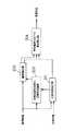
図12は、シフト演算手段8の構成の一例を示す。図12において、9はMPU、10は融合範囲テーブルである。MPU9は画像表示面の幅と観察距離から(数15)に示す水平方向の視野角を計算し、該視野角における融合範囲を融合範囲テーブル10から読み出す。
【0065】
【数15】
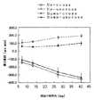
図13は融合範囲テーブルの特性の1例を示す。図13において、横軸は画像表示面の水平方向の視野角であり、縦軸は視差の融合範囲((数16)により角度換算している)である。
【0067】
【数16】
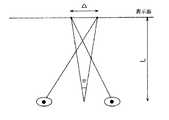
なお、図13の縦軸の符号は負の側が表示面よりも手前に知覚される視差、正の側が表示面よりも奥に知覚される視差を示している。図14は、(数16)の図形的な意味を示す図である。図14は、角度換算した視差θは画像表示面上での視差Δを視野角に換算したものであることを示す。
【0069】
一方、図1および図3に示す平行投影と輻輳投影において、画像の位置(例えば液晶プロジェクタであれば液晶上の画素の位置)xl1,xr1 と表示面上での位置Xl,Xr の位置関係は、それぞれ(数17)(数19)となり、表示面上での視差は(数18)(数20)となる。
【0070】
【数17】
【数18】
【数19】
【数20】
そして、撮影時の撮影面上での座標値(xl0,yl0),(xr0,yr0)と、投影時の画像の位置(xl1,yl0),(xr1,yr1)(例えば液晶プロジェクタであれば液晶上の画素の位置)との関係は、(数21)で表される。
【0075】
【数21】
ここで、撮像面の幅winはカメラパラメータから得られ、表示時の画像幅woutは表示系固有の値である。
【0077】
撮像時の条件(平行撮影/輻輳撮影)に応じて(数5)もしくは(数8)を用いてxl0,xr0を計算し、(数21)によりxl1,xr1に変換する。更に、投影時の条件(平行投影/輻輳投影)に応じて、(数18)もしくは(数20)を計算することにより、撮像条件、投影条件の双方を考慮して、表示画面上での視差を計算できる。
【0078】
MPU9は、融合範囲テーブル10から読み出した融合範囲を表示面上での視差(距離)に換算し、画像表示面上での視差の融合範囲を決定する。そして、MPU9は、上述した画像データにおける視差と画像表示面上での視差の関係とを用いて、融合範囲内の視差の頻度の和が最大になるような、画像データに対するシフト量を計算する(視差制御による画像のシフトは、視差の頻度分布を図15において水平方向に移動させることを意味する)。
【0079】
画像シフト手段4a,4bによって該出力シフト量だけ逆方向に画像をシフトし、画像表示手段5a,5bによって表示することにより、融合範囲内での視差の頻度の和が最大(すなわち画像内で融合する画素の面積が最大)になる表示を行うことができる。
【0080】
以上説明したように、本実施の形態によれば、人の目の融合範囲に応じた視差制御を行うことによって、表示時に画像のより多くの部分で視差を融合範囲内に入るようにすることができる。
【0081】
なお、本実施の形態では、融合範囲内での視差頻度の和が最大になる視差制御について説明したが、視差の平均値が融合範囲の中央になるように視差制御してもほぼ同等の効果を得ることができ、本発明に含まれる。
【0082】
また、伝送側において、最近点及び最遠点を、実際の画像中の最近点及び最遠点とは異なる値に設定し、表示側において該設定値の最近点及び最遠点に相当する各々の視差の平均の視差が、融合範囲の中央になるように視差制御することにより、画像作成者の意図する奥行きでの画像を優先的に観察者に提示することができ、本発明に含まれる。
(第3の実施の形態)
本発明の第3の実施の形態は、1組の画像対を入力し、初期視差と初期視差の信頼性とを計算し、基準画像と初期視差の信頼性とから物体輪郭線を検出し、初期視差と初期視差の信頼性と検出された物体輪郭線とから、物体輪郭線近傍の初期視差の信頼性の低い領域での視差を決定する。このとき視差は、物体輪郭線において変化し、かつ、周囲の視差とは滑らかに接続するように決定する視差推定方法およびその装置である。
【0083】
本実施の形態では前述した構成により、基準画像と参照画像の1組の画像対から、初期視差と初期視差の信頼性とを計算し、基準画像と初期視差の信頼性とから物体輪郭線を検出し、初期視差と初期視差の信頼性と検出された物体輪郭線とから、物体輪郭線近傍の初期視差の信頼性の低い領域での視差が、物体輪郭線において変化し、かつ、周囲の視差とは滑らかに接続するように決定する。
【0084】
図16は、本発明の第3の実施の形態における視差推定装置のブロック図である。
【0085】
図16において、201はブロックマッチングによる初期視差を計算する初期視差推定部、202は初期視差推定時の信頼性評価部、203は輪郭検出部、204は物体輪郭付近での視差推定部である。
【0086】
以下に上記構成の動作について説明する。
【0087】
初期視差推定部201は、(数22)に示す残差平方和(Sum of Squared differences 以下SSD)の計算を行う。(数22)によるSSDの値は、基準画像に設定した窓領域と参照画像中に設定した窓領域内の画素値の分布が似ているところでは小さな値となり、逆に双方の窓領域内での画素値の分布が異なるところでは大きな値となる。初期視差推定部201は、所定の探索範囲内でSSDの値を最小とする画像間のずれ量dを着目点(x,y)における視差とし、その視差の値を物体輪郭付近での視差推定部204に出力し、探索範囲内でのSSDの最小値を初期視差推定時の信頼性評価部202に出力する。
【0088】
【数22】
図17は、初期視差推定部201による上記初期視差推定(ブロックマッチング)を説明する図である。図17において、着目点(x,y)を中心にして設定した窓領域が、(数22)の積分領域Wを示す。窓領域を順次ずらして設定し、上記のSSDの計算を行うことにより画像全体での初期視差を得ることができる。
【0090】
初期視差推定時の信頼性評価部202は、初期視差推定部201による視差計算で得られたSSDの探索範囲中での最小値、窓領域(ブロック)内の画素数、画像間のノイズの分散、窓領域内での基準画像の水平垂直方向の輝度こう配の2乗の平均値から、(数23)に示す対応付けの信頼性評価値を計算する。
【0091】
【数23】
(数23)の値は、小さいほど視差推定の信頼性が高いことを示し、逆に大きいほど信頼性が低いことを示す。
【0093】
図18は、輪郭検出部203の構成の一例を示すブロック図である。図18において、205は基準画像を輝度成分と色成分に分離するYC分離回路、206A,206B,206Cは、上記分離された輝度成分Y、色成分R−Y,B−Yからそれぞれエッジを検出するエッジ検出回路、207はエッジ検出結果の稜線における強度のみを出力する稜線検出部、208は初期視差推定値の信頼性の低い領域で1の重みを出力し、初期視差推定値の信頼性の高い領域では0の重みを出力する重み発生回路である。
【0094】
以下に上記構成の動作について説明する。
【0095】
YC分離回路205は、基準画像を輝度成分Y、色成分R−Y,B−Yに分離し出力する。
【0096】
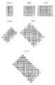
エッジ検出回路206A,206B,206Cはそれぞれ、上記Y,R−Y,B−Y成分からエッジ成分を検出する。図19は、エッジ検出回路206の構成の一例を示すブロック図である。図19において、209A,209B,209Cはそれぞれ低空間周波数域、中空間周波数域、高空間周波数域におけるエッジ成分を検出する方向別フィルタ群である。210、211、212、213は、それぞれの方向別フィルタ群を構成する方向別フィルタである。図20は、上記方向別フィルタの空間的な重みの一例であり。図20(a),(b),(c)は垂直方向に連続するエッジを、(d),(e),(f)は斜め方向のエッジを検出するものである。
【0097】
尚、(a),(d)が高空間周波数域、(b),(e)が中空間周波数域、(c),(f)が低空間周波数域用の重みの分布の一例を示す。水平および他方の斜め方向のエッジ検出は、図20の計数の配置を90度回転させればよい。また、エッジの方向は45度刻みに限る必要はなく、30度刻みなどでもよいのは当然である。
【0098】
また、方向別フィルタの空間的な重みは図20に示すものに限る必要はなく、方向毎についての微分型の重み分布になっていればよいのは当然である。各方向別のエッジ強度の算出法を式で示すと(数24)になる。
【0099】
【数24】
統合部214は方向別フィルタ210,211,212,213の出力を統合する。統合部214による統合の一例を式で示すと(数25)になる。
【0101】
【数25】
尚、統合部214による統合は(数25)で示される2乗和の形式のものに限る必要はなく、絶対値和の形式のものなどでもよいのは当然である。
【0103】
輝度成分Y、色成分R−Y,B−Yについて、高空間周波数域、中空間周波数域、低空間周波数域でそれぞれ統合部214A,214B,214Cにより統合されたエッジ強度は、乗算され出力される。そして、Y,R−Y,B−Y各成分についての上記エッジ強度は、加算され稜線検出部7に転送される。
【0104】
尚、輪郭検出部203における基準画像の輝度成分、色成分への分離はY,R−Y,B−Yに限る必要はなく、R,G,B等他の成分へ分離してもよいのは当然である。また、Y,R−Y,B−Yについての上記エッジ強度は加算後に稜線検出部207に転送するものに限る必要はなく、乗算後に稜線検出部207に転送してもよい。
【0105】
図18に戻って、稜線検出部207は、上記Y,R−Y,B−Yについて加算されたエッジ強度の稜線における値のみを出力する。図21は、稜線検出部207の構成の一例である。図21において、水平稜線検出回路215は着目画素でのエッジ強度が着目点の上下の画素でのエッジ強度の双方よりも大きい場合に1を出力し、そうでない場合には0を出力する。
【0106】
同様に、垂直稜線検出回路216は着目画素でのエッジ強度が着目点の左右の画素でのエッジ強度の双方よりも大きい場合に1を出力し、そうでない場合には0を出力する。水平稜線検出回路215と垂直稜線検出回路216の出力は、OR演算され、更に入力信号と乗算して出力される。すなわち、稜線検出部207は、水平方向もしくは垂直方向に隣接する画素でのエッジ強度よりも強いエッジ強度を有する画素(すなわち稜線となっている画素)におけるエッジ強度のみを出力し、その他の画素については0を出力する。
【0107】
再び図18に戻って、重み発生回路208は、初期視差推定値の信頼性評価値がしきい値以上の時1を出力し、しきい値未満の時には0を出力する。重み発生回路208の出力を稜線検出部207の出力と乗算することにより、初期視差推定値の信頼性が低いところでのエッジ、すなわち視差が不連続に変化する物体輪郭線を抽出できる。また、重み発生回路208の出力は、後述する物体輪郭付近での視差推定部204の演算領域メモリに記憶される。物体輪郭線の抽出を式で示すと(数26)となる。
【0108】
【数26】
尚、エッジ検出結果206A,206B,206Cの出力を加算して稜線検出部7に入力するように限る必要はなく、乗算して稜線検出部207に入力してもよい。また、稜線検出部207の出力と乗算される重み発生回路208による重み発生の方法は、0と1の2値に限る必要はなく、初期視差推定時の信頼性に応じて連続的な値を出力してもよいのは当然である。
【0110】
物体輪郭付近での視差推定部204は、物体輪郭線近傍の初期視差推定値の信頼性の低い領域での視差を、輪郭強度、初期視差から再計算する。物体輪郭付近での視差推定部204は、(数27)で定義される視差の分布についてのエネルギーを最小化する視差分布を計算する。
【0111】
【数27】
重み関数w(x,y)は滑らかさのパラメータと輪郭強度により(数28)として定義する。
【0113】
【数28】
(数27)を最小にする視差分布の条件は(数29)である。
【0115】
【数29】
(数29)の微分方程式は、有限要素法(FEM)等の公知の技術によって数値的に解くことができる。
【0117】
図22は、物体輪郭付近での視差推定部204の構成の一例を示すブロック図である。図22において、217は視差分布エネルギー用の重みを発生する視差分布エネルギー用重み発生回路、218は演算領域メモリ、219は視差メモリ、220は重みメモリ、221はFEM演算回路である。
【0118】
視差分布エネルギー用重み発生回路217は、輪郭強度と滑らかさのパラメータλから(数28)の重み関数の値を計算し、重みメモリ220に書き込む。FEM演算回路221は、(数29)を有限要素法により解き、視差分布を計算する。
【0119】
以上のように本実施の形態によれば、ブロックマッチングによる視差推定値の信頼性が低い領域において、物体輪郭線を検出し、検出した物体輪郭線の所で視差が不連続に変化するように視差推定を行うことができる。
【0120】
また、本実施の形態によれば、任意の形状の物体輪郭線の所で視差が不連続に変化するように視差推定を行うことができる。
【0121】
尚、物体輪郭付近での視差推定は、視差が物体輪郭線の所で変化し、かつ、周囲の視差と滑らかに接続すればよく、(数27)に示すエネルギーを最小化する視差として計算する方法に限る必要はない。そのような例について、以下に説明する。
(第4の実施の形態)
図23は、本発明の第4の実施の形態における視差推定装置の構成を示すブロック図である。図23において、201はブロックマッチングによる初期視差を計算する初期視差推定部、202は初期視差推定時の信頼性評価部、222は輪郭検出部、223は物体輪郭付近での視差推定部である。
【0122】
上記構成において、輪郭検出部222、物体輪郭付近での視差推定部223以外の構成の動作は本発明の第3の実施の形態と同一であるので説明を省略し、以下に輪郭検出部222、物体輪郭付近での視差推定部223の動作について説明する。
【0123】
まず、輪郭検出部222は、本発明の第3の実施の形態における輪郭検出部と同様の輪郭検出を行ない、検出結果を2値化(例えば、0と1)して出力する。物体輪郭付近での視差推定部223は、物体輪郭線近傍の初期視差推定値の信頼性の低い領域での視差を、初期視差と輪郭検出部222によって検出された物体輪郭線とから計算する。
【0124】
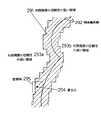
図24は、物体輪郭付近での視差推定部223による視差推定の様子を示す図である。図24において、291は初期視差推定値の信頼性の低い領域、292は輪郭検出部222によって検出された物体輪郭線、293は初期視差推定値の信頼性の高い領域、294は視差を計算しようとする着目点、295は着目点を含むように設定した窓領域である。
【0125】
着目点294(x,y)における視差は、設定窓領域内で初期視差推定値の信頼性の低い領域291と接する周囲の領域(この場合は、初期視差推定値の信頼性の高い領域293a)での視差を用い、着目点294での視差が、周囲の領域と着目点294との距離に応じて、周囲の領域での視差の値の影響を受けるように決定する。この時、周囲の領域における視差は、物体輪郭線292を越えて着目点294に影響を与えないようにすることにより、物体輪郭線292の所で変化し、かつ、周囲の視差と滑らかに接続するするように視差を決定できる。物体輪郭付近での視差推定部223による視差推定を一例として式で表すと(数30)となる。
【0126】
【数30】
ただし、物体輪郭付近での視差推定部223による視差推定は、(数30)に限る必要はなく、視差が物体輪郭線で変化し、かつ、周囲の視差と滑らかに接続するものであればよいのは当然である。
【0128】
以上のように本実施の形態によれば、ブロックマッチングによる視差推定値の信頼性が低い領域において、物体輪郭線を検出し、検出した物体輪郭線の所で視差が不連続に変化するように視差推定を行うことができる。
【0129】
また、本実施の形態によれば、任意の形状の物体輪郭線の所で視差が不連続に変化するように視差推定を行うことができる。
【0130】
さらに、本実施の形態によれば、初期視差推定値の信頼性の低い領域において、着目点近傍で比較的少数の周囲の視差を参照して視差を計算することにより、少ないメモリ容量と演算量で視差の計算を行うことができる。
【0131】
また、第3と第4の実施の形態で説明した視差推定の結果を用いて、左右の画像をシフトし統合することにより、それら左右の画像に対応する各々の視点の間の所定の中間視点における画像を生成できる。ここで、視差推定と中間視点画像生成とは異なる場所で行ってもよい。以下に、視差推定と中間視点画像生成とを異なる場所で行う際の伝送、受信方法について説明する。
(第5の実施の形態)
図25は、本発明の第5の実施の形態において、送信側で視差推定(もしくは動き推定)を行うシステムの送信ブロックの一例である。
【0132】
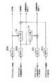
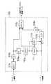
図25において、170は左画像を基準とした視差VL を推定する視差推定手段、171は右画像を基準とした視差VR を推定する視差推定手段、172a〜dは符号化器、173a,bは復号化器、174は左画像Lと左画像を基準とした視差VL から右画像Rを予測する予測手段、175は左画像を基準とした視差VLから右画像を基準とした視差VRを予測する予測手段、176a,bは視差が正しく推定されない領域での視差を決定する穴埋め手段である。以下に上記構成の動作について説明する。
【0133】
まず、左画像Lは符号化器172aによって符号化される。また、視差推定手段170、171によって左右の画像をそれぞれ基準とした視差VL,VRが推定される。オクルージョン等により視差が正しく推定されない領域については、第3または第4の実施の形態で説明した視差推定方法を用いた穴埋め手段176a,176bによって視差が決定される。
【0134】
次に、左画像を基準とした穴埋め後の視差は符号化器172bにより符号化される。符号化された左画像を基準とした穴埋め後の視差は、復号化器173aにより復号化され、予測器174による右画像Rの予測と、予測器175による穴埋め後の右画像を基準とした視差の予測に用いられる。予測器175による右画像を基準とした視差VR の予測は、左画像を基準とした視差を用いて、(数31)として計算する。
【0135】
【数31】
右画像Rは予測器174による予測画像との残差をとり、符号化器172dによって符号化される。右画像を基準とした穴埋め後の視差VR は、予測器175による予測視差との残差をとり、符号化器172cにより符号化される。
【0137】
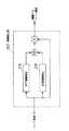
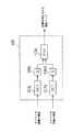
図26は、受信側で視差推定を行うシステムの受信ブロックの一例である。図26において、181a〜dは復号化器、174は右画像Rの予測器、175は右画像を基準とした視差の予測器である。符号化された左画像L、左画像基準の視差VL、右画像基準の視差VRの予測誤差、右画像Rの予測誤差はそれぞれ復号化器181a〜181dにより復号化される。右画像Rは予測器174による予測結果と復号化された右画像の予測誤差とを加算して復元される。右画像基準の視差VR は、予測器175による予測結果と復号化された予測誤差とを加算して復元される。
【0138】
左画像L、右画像R、左画像基準の視差VL、右画像基準の視差VRが復元されると、例えば特願平7−109821号に示される中間視点画像生成方法により左右の画像の中間視点での画像を生成することができ、左画像、右画像と併せて多視点画像として表示することができる。
【0139】
以上説明したように、上記の構成により、送信側で視差推定と穴埋め処理を行うことにより、受信側での演算量を低減することができ、受信側の装置規模を縮小することができる。
【0140】
また、多視点画像を伝送する際に、送信側で中間視点画像生成を行うことにより伝送量を低減した画像伝送を行うことができる。そのような例について以下に説明する。
(第6の実施の形態)
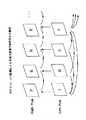
図27は、本発明の第6の実施の形態における多視点画像圧縮伝送システムの送信側の構成図である。図27において、101a〜101dは各視点位置での画像を撮像するカメラ、102はカメラ1の画像とカメラ4の画像を圧縮し符号化する画像圧縮符号化部、103aは画像圧縮符号化部102が圧縮符号化した画像データを復号化伸長する復号化画像伸長部、104aは復号化画像伸長部103aが復号化伸長したカメラ1の画像とカメラ4の画像から、カメラ2の視点とカメラ3の視点での画像を予測し生成する中間視点画像生成部、105はカメラ2の画像とカメラ3の画像について中間視点画像生成部104aが生成した画像との残差を圧縮し符号化する残差圧縮符号化部である。以下に上記構成の動作について説明する。
【0141】
画像圧縮符号化部102は、多視点画像中の複数の画像(本実施の形態では4視点の画像の両端の視点の画像)を、画像間のブロック相関等を利用した既存の技術により圧縮し符号化する。図31は、画像圧縮符号化部102の構成の一例を示す。図31において、107a,107bは8×8画素もしくは16×16画素毎にDCT計算を行いDCT係数を計算するDCT手段、108a,108bはDCT係数を量子化する量子化手段、109aは逆量子化手段、110aは逆DCT計算をおこなう逆DCT手段、111は視差検出手段、112aは視差補償手段、113aは量子化されたDCT係数と視差を符号化する符号化手段である。以下に上記構成の動作について説明する。
【0142】
DCT手段107aは、カメラ1の画像をブロック毎に処理し、各ブロックについてDCT係数を計算する。量子化手段108aは、そのDCT係数を量子化する。逆量子化手段109aは、その量子化されたDCT係数を逆量子化する。逆DCT手段110aは、その逆量子化されたDCT係数を逆変換し、受信側で得られるカメラ1の画像を復元する。視差検出手段111は復元されたカメラ1の画像とカメラ4の画像間でブロックマッチングを行い、カメラ1の画像を基準とした視差をブロック毎に計算する。視差補償手段112aは、上記復元されたカメラ1の画像とブロック毎の視差を用いてカメラ4の画像を予測する(すなわち、動画像の動き補償に相当する処理を行う)。DCT手段107bは、カメラ4の画像と上記予測画像の残差をブロック毎に処理しDCT係数を計算する。量子化手段108bはその残差のDCT係数を量子化する。符号化手段113aは、カメラ1の画像の量子化されたDCT係数、ブロック毎の視差、視差補償の残差の量子化されたDCT係数を符号化する。
【0143】
また、復号化画像伸長部103aは、画像圧縮符号化部102によって圧縮符号化された画像データを復号化し伸長する。図32は、復号化画像伸長部103aの構成の一例を示す図である。図32において、114aは復号化手段、109b、109cは逆量子化手段、110b,110cは逆DCT手段、112bは視差補償手段である。以下に上記構成の動作について説明する。
【0144】
復号化手段114aは、圧縮符号化されたデータを復号化し、カメラ1の画像の量子化されたDCT係数、ブロック毎の視差、視差補償の残差の量子化されたDCT係数を伸長する。カメラ1の画像の量子化されたDCT係数は、逆量子化手段109bによって逆量子化され、逆DCT手段110bによって画像として伸長される。動き補償手段112bは、その伸長されたカメラ1の画像と復号化された視差から、カメラ4の予測画像を生成する。そして、逆量子化手段109c、逆DCT手段110cによって伸長された残差を上記予測画像に加えることにより、カメラ4の画像を伸長する。
【0145】
中間視点画像生成部104aは、本発明の第3もしくは第4のいずれかの実施の形態に示す方法によって、カメラ1とカメラ4の画像から画素毎の視差を計算し、カメラ2とカメラ3の画像を予測し生成する。
【0146】
残差圧縮符号化部105は、カメラ2とカメラ3の画像と上記予測画像の残差を圧縮し符号化する。中間視点画像生成部104aは、視差を画素毎に計算するため、ブロックマッチングによるブロック毎の視差計算と比較して、精度よく視差を推定できる。その結果、中間視点画像の予測誤差(すなわち残差)を小さくすることができ、圧縮効率を高めることができるとともに、より有効なビット割り当てを行うことができ、画質を維持した圧縮を行える。図33は、残差圧縮符号化部の構成の一例を示す。図33において、107c,107dはDCT手段、108c,108dは量子化手段、113bは符号化手段である。カメラ2、カメラ3の画像の残差はそれぞれDCT手段107c,107dによってDCT係数に変換され、量子化手段108c,108dによって量子化され、符号化手段113bによって符号化される。
【0147】
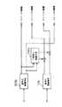
図34は、本発明の第6の実施の形態における多視点画像圧縮伝送システムの受信側の構成図である。図34において、103bは送信側の画像圧縮符号化部102が圧縮符号化したカメラ1とカメラ4の画像データを復号化伸長する復号化画像伸長部、104bは復号化画像伸長部103bが復号化伸長したカメラ1とカメラ4の画像から、カメラ2とカメラ3の視点での画像を予測し生成する中間視点画像生成部、106はカメラ2とカメラ3の視点での予測画像の予測誤差(残差)を復号化し伸長する復号化残差伸長部である。復号化画像伸長部103bおよび中間視点画像生成部104bの動作については、送信側の復号化画像伸長部103aおよび中間視点画像生成部104aの動作と同一であるので説明を省略し、以下に復号化残差伸長部の動作について説明する。
【0148】
復号化残差伸長部106は、送信側の残差圧縮符号化部105によって圧縮符号化されたカメラ2とカメラ3の視点での予測画像の予測誤差(残差)を復号化し伸長する。図35は、復号化残差伸長部106の構成の一例を示す。図35において、114bは復号化手段、109d,109eは逆量子化手段、110d,110eは逆DCT手段である。圧縮符号化されたカメラ2とカメラ3の画像の残差データは、復号化手段114bによって復号化され、それぞれ、逆量子化手段109d,109eにより逆量子化され、逆DCT手段110d,110eにより伸長される。復号化伸長されたカメラ2とカメラ3の画像の残差を、中間視点画像生成部104bによって生成された画像にそれぞれ重畳することにより、カメラ2とカメラ3の視点の画像を復元する。
【0149】
以上のように、本実施の形態によれば、送信側で、多視点画像中の隣接しない2つの画像からその中間視点の画像を生成し、その生成した中間視点画像とその中間視点の実際の画像との残差を求め、上記2つの画像と中間視点画像の残差とを圧縮符号化して伝送する。受信側で、伝送されてきた2つの画像と中間視点画像の残差とを復号化伸長し、2つの画像から中間視点の画像を生成し、復号化伸長した中間視点画像の残差を重畳して中間視点での実際の画像に対応する画像を復元する。このようにすることにより、多視点画像を効率よく、また、画質を維持して圧縮伝送することができる。
【0150】
なお、中間視点画像の生成は、多視点画像の両端の2視点(カメラ1とカメラ4の視点)での画像から中間視点での画像を生成する構成に限る必要はなく、例えば、カメラ2とカメラ4の画像からカメラ1とカメラ3の視点での画像を生成してもよく、カメラ1とカメラ3の画像からカメラ2とカメラ4の視点での画像を生成してもよい。更には、カメラ2とカメラ3の画像からカメラ1とカメラ4の視点での画像を生成してもよく、それぞれ本発明に含まれる。
【0151】
また、多視点画像の視点数は4視点に限る必要はなく、また、2視点以上の視点での画像からそれぞれの視点間の中間視点画像を生成してもよいのは明らかであり、本発明に含まれる。
【0152】
また、本発明の第3および第4の実施の形態において、初期視差推定値の信頼性評価値としては、(数23)に示すものに限る必要はなく、(数23)の分子のみを信頼性評価値としても、参照画像の輝度こう配の影響を受けるがほぼ同様の効果を得ることができ本発明に含まれる。
【0153】
また、画像のノイズレベルが低い場合には、信頼性評価値としてノイズ項を無視した値を計算しても同様の効果が得られるのは当然であり本発明に含まれる。
【0154】
さらに簡略化して、信頼性評価値として、1画素当たりの残差平方和の最小値、あるいは残差平方和の最小値を用いてもよく、より簡単な回路で計算が可能となり、本発明に含まれる。
【0155】
また、初期視差推定値の信頼性評価値としては、(数32)に示す双方向に推定した視差の差異を用いてもよく、本発明に含まれる。
【0156】
【数32】
また、初期視差推定の信頼性評価値としては、上記のものを2つ以上組み合わせて用いることにより、より安定した信頼性評価をすることができ、本発明に含まれる。
【0158】
また、本発明の第3および第4の実施の形態において、初期視差推定のための画像間の相関演算は残差平方和(SSD)に限る必要はなく、残差絶対値和(SAD)を用いても同様の効果を得ることができ、そのような実施の形態ももちろん本発明に含まれる。
【0159】
また、本発明の第6の実施の形態において、隣接しない2つの視点での画像の圧縮符号化の方法としては、画像間(視点間)の相関を利用したものに限る必要はなく、時間方向の相関を利用したものを用いてもよく、本発明に含まれる。
【0160】
【発明の効果】
以上のように本発明によれば、カメラの撮像面(CCD)のサイズと、撮像面とレンズ中心との距離と、レンズの焦点距離に関する情報とを付加して伝送することにより、撮影時の視野角に応じた表示を行おうとする際、被写体に接近して撮影した映像についても、表示側で撮影時の視野角を精度よく計算することができ、撮影時と同一の視野角を再現する観察距離を精度よく決定できる。
【0161】
また、多視点画像を伝送する際に画像内の最近点、最遠点の情報を付加することにより、表示時に目の疲れない表示(視差制御)を行うことができる。
【0162】
また、人の目の融合範囲に応じた視差制御を行うことによって、表示時に画像のより多くの部分で視差を融合範囲内に入るようにすることができる。
【0163】
また、伝送側において、付加する最近点、最遠点の情報として、実際の画像中の最近点、最遠点とは異なる値を設定し、表示側において該設定値の最近点に相当する視差と、最遠点に相当する視差の平均の視差が、融合範囲の中央になるように視差制御することにより、画像作成者の意図する奥行きでの画像を優先的に観察者に提示することができる。
【0164】
また、本発明によれば、ブロックマッチングによる視差推定値の信頼性が低い領域において、物体輪郭線を検出し、検出した物体輪郭線の所で視差が不連続に変化するように視差推定を行うことができる。
【0165】
また、任意の形状の物体輪郭線の所で視差が不連続に変化するように視差推定を行うことができる。。
【0166】
また、送信側で視差の穴埋め処理(本発明による、視差が物体輪郭線の所で変化し、かつ、周囲の視差と滑らかに接続する視差推定処理)を行うことにより、受信側での演算量を低減することができ、受信側の装置規模を縮小することができる。
【0167】
また、多視点画像伝送システムの送信側と受信側の双方で中間視点画像の生成を行うことにより、中間視点画像の伝送量(残差の伝送量)を少なくすることができ、その結果多視点画像を効率よく、また、画質を維持して圧縮伝送することができる。
【図面の簡単な説明】
【図1】本発明の第1の実施の形態における平行投影の場合の最近点、最遠点、観察者の輻輳と調節が一致する点の位置関係を示す図
【図2】同被写体の位置、合焦時の撮像面の位置と焦点距離の関係を示す図
【図3】同2つのプロジェクタを用いて輻輳投影をする場合の輻輳距離、最近点、最遠点の位置関係を示す図
【図4】本発明の第1の実施の形態における画像伝送方法で定義するパラメータを示す図
【図5】画像間の視差の平均値を相殺するようにずらす処理のブロック図
【図6】左画像を基準としてブロックマッチングにより視差を計算する場合を示す図
【図7】平行撮影の場合を示す図
【図8】輻輳撮影の場合を示す図
【図9】(a)〜(c)は、(数14)による重み付け平均の計算に用いる重みの分布の例を示す図
【図10】画像復号手段の動作を示す図
【図11】本発明の第2の実施の形態における視差制御方式のブロック図
【図12】シフト演算手段の構成の一例を示す図
【図13】融合範囲テーブルの特性図
【図14】(数16)の図形的な意味を示す図
【図15】視差の頻度分布図
【図16】本発明の第3の実施の形態による視差推定装置の構成図
【図17】同ブロックマッチングを示す図
【図18】同輪郭検出部の構成図
【図19】同エッジ検出部の構成の一例を示す構成図
【図20】(a)〜(f)は、同方向別のフィルタの重み係数の例を示す図
【図21】同稜線検出部の構成図
【図22】同物体輪郭付近での視差推定部の構成図
【図23】本発明の第4の実施の形態による視差推定装置の構成図
【図24】同物体輪郭線近傍での視差推定を示す図
【図25】本発明の第5の実施の形態で送信側で視差推定を行うシステムの送信部の構成図
【図26】本発明の第5の実施の形態で送信側で視差推定を行うシステムの受信部の構成図
【図27】本発明の第6の実施の形態における多視点画像伝送システムの送信部の構成図
【図28】MPEG−2シンタックスの概略図
【図29】伝送される多視点画像の時空間方向の関係図
【図30】OpenGLによるカメラパラメータの定義を示す図
【図31】本発明の第6の実施の形態における多視点画像伝送システムの画像圧縮符号化部の構成の一例を示す図
【図32】本発明の第6の実施の形態における多視点画像伝送システムの復号化画像伸長部の構成の一例を示す図
【図33】本発明の第6の実施の形態における多視点画像伝送システムの残差圧縮符号化部の構成の一例を示す図
【図34】本発明の第6の実施の形態における多視点画像伝送システムの受信部の構成図
【図35】本発明の第6の実施の形態における多視点画像伝送システムの復号化残差伸長部の構成の一例を示す図
【符号の説明】
A 表示される画像の最近点
B 最遠点
C 観察者の輻輳と調節が一致する点
A1,A2 カメラのレンズ中心
B1,B2 画像面の中心
C1 輻輳点
201 初期視差推定部
202 初期視差推定時の信頼性評価部
203 輪郭検出部
204 物体輪郭付近での視差推定部[0001]
BACKGROUND OF THE INVENTION
The present invention relates to a multi-view image transmission method and a multi-view image display method. The present invention also relates to a method for generating an intermediate viewpoint image of a multi-viewpoint image, a parallax estimation method, and an apparatus therefor.
[0002]
[Prior art]
Conventionally, various stereoscopic video methods have been proposed, but a multi-view stereoscopic video method using multi-viewpoint images is promising as a method for observing a stereoscopic moving image by a plurality of people without wearing special glasses. . In the multi-view stereoscopic video system, the more the number of cameras and display devices used, the more the observer can feel natural motion parallax, and the observation with a large number of people becomes easier. However, there are limits to the number of cameras that can be used practically due to restrictions such as the scale of the imaging system and the setting of the optical axis of the camera. In the transmission and storage processes, it is desired to reduce the amount of information that increases in proportion to the number of cameras.
[0003]
Therefore, if a multi-view stereoscopic image can be displayed by generating an intermediate viewpoint image from a binocular stereo image on the display side, the burden on the imaging system can be reduced, and the amount of information during transmission and storage can be reduced. become. In order to generate an intermediate viewpoint image that should be seen at an arbitrary viewpoint between the different viewpoints from a plurality of images having different viewpoints, it is necessary to estimate the depth by obtaining the correspondence of the pixels between the images.
[0004]
Further, MPEG-1 and MPEG-2 have been proposed as image compression methods for digital transmission of moving images. Furthermore, an attempt has been made to extend MPEG-2 and transmit multi-viewpoint images (ISO / IEC13818-2 / PDAM3). FIG. 28 is a schematic diagram of MPEG-2 syntax. Transmission by MPEG-2 is performed by encoding and decoding image data having a hierarchical structure of Sequence, GOP (Group Of Picture), and Picture. According to ISO / IEC13818-2 / PDAM3, transmission of multi-viewpoint images by extension of MPEG-2 seems to be realized by extending the GOP layer (although it is not clear because it is not specified).
[0005]
FIG. 29 shows the relationship in the spatio-temporal direction of transmitted multi-viewpoint images. In addition to the motion compensation that has been used in the conventional MPEG-2, an attempt is made to increase the coding efficiency by using parallax compensation. When transmitting a multi-viewpoint image, it is necessary to add and transmit information about each camera (camera parameters such as the position of the camera and the direction of the optical axis of the camera). In ISO / IEC13818-2 / PDAM3, it is described that the camera parameters are included in the Pic.Extension (extension of the Picture layer) in FIG. 28 and transmitted, but specific description of the camera parameters is described. Absent.
[0006]
Regarding the description of camera parameters, in OpenGL, which is a CG language, the camera position, the direction of the optical axis of the camera, and the distance between the camera position and the image plane are defined as camera parameters ("Open GL Programming Guide" ( OpenGL Programming Guide, The Official Guide to Learning OpenGL,
[0007]
FIG. 30 is an explanatory diagram showing the definition of camera parameters by OpenGL. In FIG. 30, A is the lens center, B is the center of the image plane (that is, the imaging plane), and C is the intersection of the perpendicular line from B to the upper end of the image and the upper end of the image. The coordinate values of A, B, and C are respectively
(OpticalcenterX, opticalcenterY, opticalcenterZ), (imageplanecenterX, imageplanecenterY, imageplanecenterZ), (imageplaneverticalX, imageplaneverticalY, imageplaneverticalZ).
[0008]
It is easily conceivable to transmit the multi-viewpoint image by adding the camera parameter information defined in the above OpenGL to Pic.Extension.
[0009]
[Problems to be solved by the invention]
However, in the conventional method as described above, the fundamental problem in the correspondence between images for generating the intermediate viewpoint image is that the occlusion occurs in the object contour line in which the depth changes discontinuously, and thus the correspondence between the images. It is difficult to obtain the value accurately. However, the estimated parallax value in the vicinity of the object contour line is very important when the intermediate viewpoint image is synthesized because it determines the contour position of the object in the generated intermediate viewpoint image. That is, if a parallax estimation error occurs in the vicinity of the object outline during parallax estimation, the pixels in the foreground area stick to the background side, or conversely, the pixels in the background area stick to the foreground, and the object outline is distorted. A false contour is generated in the background region in the vicinity of the line.
[0010]
In view of this point, an object of the present invention is to provide a parallax estimation method and apparatus for accurately estimating an abrupt change (discontinuous change) in the vicinity of an object outline.
[0011]
[Means for Solving the Problems]
FirstThe present invention (corresponding to claim 1) calculates the initial parallax of two captured images and the reliability evaluation value of the initial parallax, and uses the reliability evaluation value and the edge detection result of the image to determine that the parallax is not present. Extract continuously changing object outlines and based on the reliability evaluation value, Including the object outlineExtracting the region with low reliability of the initial parallax, and the parallax in the region with low reliability of the extracted initial parallax isIn the unreliable areaDecide to connect smoothly to the surrounding parallax and change in the object outline.,The parallax estimation method is characterized by performing parallax estimation that changes discontinuously in the object outline.
Also,SecondAccording to the present invention (corresponding to claim 2), the parallax in the region where the initial parallax is low in reliability is determined so as to minimize the energy of the parallax distribution defined using the parallax and the object contour line. CharacterizeOf the first inventionThis is a parallax estimation method.
Also,ThirdThe present invention (corresponding to claim 3) is characterized in that the edge detection is performed by integrating the outputs of the direction filters having different frequency characteristics.Of the first or second inventionThis is a parallax estimation method.
Also,4thThe present invention (corresponding to claim 4) is characterized in that the edge detection further performs ridge line extraction on the integrated result of the outputs of the direction-specific filters having different frequency characteristics.Of the third inventionThis is a parallax estimation method.
Also,5thAccording to the present invention (corresponding to claim 5), the reliability evaluation value of the initial parallax uses a residual sum of squares at the time of initial parallax calculation.Any one of the first to fourth aspects of the present inventionThis is a parallax estimation method.
Also,6thThe present invention (corresponding to claim 6) is characterized in that the initial parallax reliability evaluation value uses a residual sum of squares per pixel at the time of initial parallax calculation.Any one of the first to fourth aspects of the present inventionThis is a parallax estimation method.
Also,7thThe present invention (corresponding to claim 7) is characterized in that the reliability evaluation value of the initial parallax is calculated using a residual sum of squares at the time of initial parallax calculation, an image noise level, and a luminance gradient.Any one of the first to fourth aspects of the present inventionThis is a parallax estimation method.
Also,8thThe present invention (corresponding to claim 8) is characterized in that the reliability evaluation value of the initial parallax is calculated using a difference in correspondence of the initial parallax calculated with reference to both the left and right images.Any one of the first to fourth aspects of the present inventionThis is a parallax estimation method.
Also,9thAccording to the present invention (corresponding to claim 9), the reliability evaluation value of the initial parallax isAny of the fifth to eighth aspects of the present inventionThe parallax estimation method is characterized by calculating by combining two or more of the parallax estimation methods.
Also,10thAccording to the present invention (corresponding to claim 10), the initial parallax and the reliability evaluation value of the initial parallax are calculated based on the left and right images from the binocular image, and the parallax in the region where the initial parallax cannot be calculated correctly The recalculation is performed by the method according to any one of
Also,EleventhThe present invention (corresponding to claim 11)10th inventionThe encoded signal transmitted by the image transmission method is received, the binocular image and the recalculated disparity are decoded from the received signal, the decoded binocular image and the decoded recalculated This is an image display method for generating an intermediate viewpoint image using parallax and displaying the intermediate viewpoint image and the binocular image together as a multi-view image.
Also,12thAccording to the present invention (corresponding to claim 12), a representative image is selected from a multi-view image, and an unselected image is:2Each representative image as a reference imageThe initial parallax of the two captured images and the reliability evaluation value of the initial parallax are calculated, and the reliability evaluation value and the edge detection of the image are calculated.Using the output result, an object contour line in which the parallax changes discontinuously is extracted, a region with low reliability of the initial parallax is extracted based on the reliability evaluation value, and the reliability of the extracted initial parallax is low The parallax in the region performs disparity estimation that changes discontinuously in the object outline by determining to be smoothly connected to the surrounding parallax and to change in the object outline EstimatedPrediction using the parallax calculated by the method and the two representative images, calculating a residual between the unselected image and the predicted image, and encoding a prediction error between the representative image and the unselected image This is a multi-viewpoint image transmission method characterized in that it is transmitted in the form of an image.
Also,ThirteenthThe present invention (corresponding to claim 13)Of the twelfth aspect of the present inventionThe encoded signal transmitted by the image transmission method is received, the representative image is decoded, and each of the representative images is used as a reference image.Any of the first to fourth aspects of the present inventionThe parallax is calculated by the method, the image that is not selected as the representative image by the transmission unit is predicted using the representative image and the parallax, the prediction error of the unselected image is decoded, and the prediction error is A multi-viewpoint image restoration method is characterized in that a multi-viewpoint image is restored by being superimposed on a predicted image.
Also,14thAccording to the present invention (corresponding to claim 14), the representative image is encoded by predicting another representative image from one representative image and a parallax calculated with respect to the other representative image on the basis of the representative image. And encoding the prediction error between the representative image and the other representative image.Of the twelfth aspect of the present inventionThis is a multi-viewpoint image transmission method.
Also,15thThe present invention (corresponding to claim 15) detects an initial parallax estimation unit that calculates initial parallax between two captured images, a reliability evaluation value that calculates a reliability evaluation value of the initial parallax, and an edge of the image Using the contour detection unit, the reliability evaluation value and the edge detection result of the image to extract an object contour line in which the parallax changes discontinuously, and based on the reliability evaluation value, Including the object outlineExtracting the region with low reliability of the initial parallax, and the parallax in the region with low reliability of the extracted initial parallax isIn the unreliable areaA parallax estimation unit that performs smooth parallax estimation that discontinuously changes in the object contour line so as to smoothly connect to surrounding parallaxes, and to change in the object contour line This is a featured parallax estimation apparatus.
[0012]
DETAILED DESCRIPTION OF THE INVENTION
Hereinafter, the present invention will be described with reference to the drawings illustrating embodiments thereof.
(First embodiment)
FIG. 4 is a diagram showing parameters defined in the image transmission method according to the first embodiment of the present invention. In FIG. 4, A1 and A2 indicate the position of the camera lens center, and B1 and B2 indicate the center of the imaging surface (for the sake of simplicity, the imaging surface is folded back toward the subject with respect to the lens center. ing).
[0013]
In OpenGL, the distance between A1B1 and A2B2 in FIG. 4 is defined as the focal length of the camera lens. In the present invention, the distance between the lens center of the camera and the imaging surface is defined independently of the focal length of the lens. . With this definition, the distance between the center of the lens and the imaging surface at the time of focusing can be calculated according to the distance of the subject, and an accurate viewing angle can be calculated. The viewing angle can be calculated from the size of the imaging surface and the distance between the lens center and the imaging surface.
[0014]
Hereinafter, it will be described with reference to FIG. 2 that the distance between the lens center and the imaging surface at the time of focusing varies depending on the distance between the subject and the lens center. FIG. 2 is a diagram illustrating the relationship between the position of the subject, the position of the imaging surface at the time of focusing, and the focal length. 2, A is the position of the subject, B is the point where the light from A forms an image, O is the center of the lens, F is the point where parallel light is imaged by the lens, and a is the distance between the subject and the lens center O. B represents the distance between the point B where the light from A forms an image and the lens center O, and f represents the focal length of the lens. It is known that the relationship of (Equation 1) holds between a, b, and f.
[0015]
[Expression 1]
From (Equation 1), when the subject is far from the lens so that the focal length can be ignored (a >> f), 1 / a → 0, so that b = f can be approximated. However, if the subject is relatively close to the lens, the 1 / a term cannot be ignored and b ≠ f. Therefore, in order to correctly calculate the viewing angle even when the subject is relatively close to the lens, it is necessary to define the distance between the lens center and the imaging plane independently of the focal length. Then, assuming that the width of the imaging surface is win and the height is fin, the viewing angle at the time of imaging is expressed by (Equation 2).
[0017]
[Expression 2]
Therefore, if the width of the image at the time of display is wout and the height is hout, the observation distance for reproducing the viewing angle at the time of imaging is
[0019]
[Equation 3]
It becomes.
[0021]
Next, improvement in the visibility on the display side based on the nearest point and the farthest point in the image will be described. FIG. 3 is a diagram for explaining the positional relationship between the convergence distance, the nearest point, and the farthest point when performing projection of convergence using two projectors. In FIG. 3, C represents a convergence point, A represents the nearest point, and B represents the farthest point.
[0022]
In a projection with congestion, the parallax is 0 when the observer views the convergence point C (in FIG. 3, since both eyes see the center of the image, the right and left eyes see the relative The difference in position is eliminated). When the closest point A is viewed, a so-called crossing state is obtained, and Da parallax occurs in the crossing direction on the image. In FIG. 3, the observer sees a point shifted by Da / 2 inward for both eyes compared to when viewing the convergence point C. On the contrary, when the farthest point B is viewed, a so-called distant state is obtained, and a parallax of Db is generated in the direction of the distant eye on the image.
[0023]
FIG. 1 is a diagram showing the positional relationship between the closest point, the farthest point, and the point where the convergence of the observer coincides with the adjustment in the case of parallel projection. In FIG. 1, A is the closest point of the displayed image, B is the farthest point, and C is the point where the observer's convergence and adjustment coincide. In the case of parallel projection shown in FIG. 1, when an image having a Dc parallax is displayed, it is displayed at the same point on the screen, and the convergence and adjustment of the observer coincide.
[0024]
The parallax in the images shown in FIGS. 3 and 1 is perceived by the observer as a three-dimensional effect on the front or back of the screen surface (the surface including C). It looks double), and it makes the viewer feel uncomfortable and uncomfortable.
[0025]
The improvement in the visibility of the observer is based on the closest point, the farthest point, and the convergence point at the time of imaging, with the images in the direction shown in FIG. 3 (
[0026]
FIG. 5 is a block diagram of such processing. FIG. 5 shows an example of binocular (two viewpoints) data for simplicity. In FIG. 5, 1 is an image decoding means, 2 is a parallax estimation means, 3 is an average parallax calculation means, 4a and 4b are image shift means, and 5a and 5b are image display means. The operation of each means will be described below.
[0027]
The image decoding means 1 receives the multi-view image data encoded on the transmission side and decodes it. The left and right images decoded by the
[0028]
[Expression 4]
Calculation of (Equation 4) is performed at intervals of one pixel for d in the range from dmin to dmax. Then, the value of d that minimizes the SSD in the range from dmin to dmax is set as the parallax in the set window region. The parallax at each pixel of the image can be obtained by sequentially shifting the window area and performing the above calculation.
[0030]
The ranges dmin and dmax for calculating the SSD can be calculated from information on the nearest point and the farthest point. A method for obtaining dmin and dmax in parallel shooting and convergence shooting will be described below with reference to FIGS.
[0031]
FIG. 7 is a diagram illustrating the case of parallel shooting. In the coordinate system shown in FIG. 7, the coordinate values of the left and right lens centers are (−D / 2, 0) and (D / 2, 0), the distance between the imaging surface and the lens center is b, and the object in the three-dimensional space. The horizontal coordinate value of the position is X0, the coordinate value in the depth direction is Z0, and the horizontal positions at which light from the object at the position (X0, Z0) is imaged on the left and right imaging surfaces are respectively xl0 and xr0 (xl0 and xr0 are From the graphical relationship between the horizontal coordinate of the plane coordinate system with the origin of the intersection of the camera's optical axis and the imaging surface,
[0032]
[Equation 5]
It becomes. Therefore, the parallax with reference to the left and right images is expressed by the equation shown in (Equation 6).
[0034]
[Formula 6]
Here, assuming that the depth value of the nearest point in the image is Zmin and the depth value of the farthest point is Zmax, the upper limit dmax and the lower limit dmin of the range for calculating the SSD are expressed by (Equation 7).
[0036]
[Expression 7]
FIG. 8 is a diagram showing a case of convergence imaging. In the coordinate system shown in FIG. 8, the coordinate value of the convergence point (intersection of the optical axes of the left and right cameras) is (0, C), the coordinate value of the left and right lens centers is (−D / 2, 0), (D / 2, 0), the distance between the imaging surface and the lens center, b, the horizontal coordinate value of the object position in the three-dimensional space, X0, the coordinate value in the depth direction, Z0, and the position (X0, Z0) on the left and right imaging surfaces. The horizontal positions at which the light from the object is imaged are denoted by xl0 and xr0 (where xl0 and xr0 are the horizontal coordinates of the plane coordinate system with the intersection of the optical axis of the camera and the imaging surface as the origin) and the graphic relationship,
[0038]
[Equation 8]
It becomes. Therefore, the parallax when the left and right images are used as references is expressed by the equation shown in (Equation 9).
[0040]
[Equation 9]
Since X0 remains in the equation (Equation 9), it can be seen that the parallax varies depending on the position in the horizontal direction (that is, the reproduced stereoscopic image is distorted) even if the depth is the same in the convergence imaging. Considering the parallax at a point on X0 = 0 (that is, the Z axis) for simplicity, substituting X0 = 0 into (Equation 9) gives (Equation 10).
[0042]
[Expression 10]
From (Equation 10), the disparity from the positional relationship of the depth value Zmin of the nearest point in the image, the depth value Zmax of the farthest point, the depth value C of the convergence point, the number of horizontal pixels nx, and the width win of the imaging surface (CCD) The upper limit pixel number dmax and the lower limit pixel number dmin can be determined.
[0044]
When the parallax at points other than on the Z-axis is taken into account, the upper limit dmax and the lower limit dmin of the parallax can be determined by calculating the maximum value and the minimum value of (Equation 9).
[0045]
As explained above, given the depth value of the nearest point in the image, the depth value of the farthest point, the position of the camera, and the direction of the optical axis of the camera, the range of values to be taken for the parallax can be calculated, and the parallax calculation Sometimes the range over which the SSD is calculated can be determined. The average parallax calculation means 3 calculates the average of the parallax maps calculated by the parallax estimation means 2. The average of the parallax map is obtained by calculating (Equation 11).
[0046]
## EQU11 ##
The image shift means 4a and 4b display images so that the depth point having the average parallax obtained by the average parallax calculation means 3 is displayed at the same depth as the display surface (that is, the parallax is 0 on the display surface). To shift.
[0048]
In FIG. 1 showing the display by parallel projection, A is the depth of the nearest point in the image to be displayed, B is the depth of the farthest point, and C is the depth of the average parallax. From FIG. 1, it can be seen that in parallel projection, when there is a Dc parallax expressed by (Equation 12) between the left and right images, the parallax disappears on the screen and a natural display in which the convergence and the adjustment coincide with each other.
[0049]
[Expression 12]
The image shift means 4a shifts the left image by the shift amount shown in (Equation 13) (a shift in the right direction is positive).
[0051]
[Formula 13]
Then, the image shift means 4b shifts the right image by the same amount in the reverse direction. As a result of the shift by the image shift means 4a and 4b, the points having the average parallax are displayed at the same depth as the screen.
[0053]
In FIG. 3 showing the display by the convergence projection, A indicates the depth of the nearest point in the displayed image, B indicates the depth of the farthest point, and C indicates the depth of the average parallax. In the convergence projection, when the parallax is 0 at the center of the image, the image is displayed at the same depth as the screen. Therefore, in the case of convergence projection, the image shift means 4a and 4b shift the left and right images by a value obtained by multiplying the average parallax by -1/2.
[0054]
As described above, according to the present embodiment, when transmitting a multi-viewpoint image, information on the nearest point and the farthest point in the image is added, so that the display side does not get tired of eyes (parallax control). It can be performed.
[0055]
In addition, by adding information about the size of the imaging surface (CCD) of the camera, the distance between the imaging surface and the center of the lens, and the focal length of the lens and transmitting the information, the display according to the viewing angle at the time of shooting is performed. At this time, the viewing angle at the time of photographing can be accurately calculated on the display side even for an image photographed close to the subject.
[0056]
In addition, when transmitting without adding information on the nearest point and the farthest point in the multi-viewpoint image, information on the nearest point and the farthest point is added instead of the information on the nearest point and the farthest point. It is possible to estimate the parallax at the nearest and farthest points in the image by adding a dedicated code indicating that there is no transmission and calculating the parallax within the preset range on the display side. Are included in the present invention.
[0057]
Furthermore, on the transmission side, parallax control is performed so that parallax within the set specific depth range falls within the fusion range by setting information on the nearest point and the farthest point in the multi-viewpoint image to a specific depth value. And is included in the present invention.
[0058]
In the present invention, an example in which parallax calculation is performed on the display side has been described. However, parallax included in an encoded image may be used and is included in the present invention. Such an example will be described with reference to FIG.
[0059]
In FIG. 10, the operation of the configuration other than the
[0060]
Note that the average parallax calculation by the average parallax calculation means 3 may use the weighted average value according to (Equation 14) with emphasis on the center of the screen. In this way, parallax control that facilitates fusion at the center of the image can be performed, and is included in the present invention.
[0061]
[Expression 14]
FIGS. 9A, 9B, and 9C show examples of weight distributions used for calculating the weighted average according to (Equation 14). Although it is shown one-dimensionally for simplicity, it is actually a two-dimensional distribution having a larger value at the center of the image than at the periphery. The weight values are all 0 or more (non-negative values).
(Second Embodiment)
FIG. 11 is a block diagram of a parallax control method according to the second embodiment of the present invention. In FIG. 11, the configuration other than the frequency calculation means 7 and the shift amount calculation means 8 performs the same operation as that in the first embodiment, and therefore is the same as the explanatory diagram in the first embodiment. The description will be omitted. The operations of the frequency calculation means 7 and the shift amount calculation means 8 will be described below.
[0063]
The frequency calculation unit 7 calculates the frequency of the parallax based on the left image decoded by the
[0064]
FIG. 12 shows an example of the configuration of the shift calculation means 8. In FIG. 12, 9 is an MPU, and 10 is a fusion range table. The MPU 9 calculates the viewing angle in the horizontal direction shown in (Equation 15) from the width of the image display surface and the observation distance, and reads the fusion range at the viewing angle from the fusion range table 10.
[0065]
[Expression 15]
FIG. 13 shows an example of the characteristics of the fusion range table. In FIG. 13, the horizontal axis represents the viewing angle in the horizontal direction of the image display surface, and the vertical axis represents the parallax fusion range (converted into an angle using (Equation 16)).
[0067]
[Expression 16]
In addition, the code | symbol of the vertical axis | shaft of FIG. 13 has shown the parallax by which the negative side is perceived before the display surface, and the positive side is perceived behind the display surface. FIG. 14 is a diagram showing the graphical meaning of (Equation 16). FIG. 14 shows that the parallax θ converted into an angle is obtained by converting the parallax Δ on the image display surface into a viewing angle.
[0069]
On the other hand, in the parallel projection and the convergence projection shown in FIGS. 1 and 3, the positional relationship between the position of the image (for example, the position of the pixel on the liquid crystal in the case of a liquid crystal projector) xl1, xr1 and the position Xl, Xr on the display surface is , (Equation 17) and (Equation 19) respectively, and the parallax on the display surface becomes (Equation 18) and (Equation 20).
[0070]
[Expression 17]
[Formula 18]
[Equation 19]
[Expression 20]
Then, the coordinate values (xl0, yl0), (xr0, yr0) on the photographing surface at the time of photographing and the positions (xl1, yl0), (xr1, yr1) of the image at the time of projection (for example, liquid crystal in the case of a liquid crystal projector) The relationship with the upper pixel position is expressed by (Equation 21).
[0075]
[Expression 21]
Here, the width win of the imaging surface is obtained from camera parameters, and the image width wout at the time of display is a value unique to the display system.
[0077]
Xl0 and xr0 are calculated using (Equation 5) or (Equation 8) according to the imaging conditions (parallel imaging / convergence imaging), and converted into xl1 and xr1 using (Equation 21). Further, by calculating (Equation 18) or (Equation 20) according to the projection condition (parallel projection / convergence projection), the parallax on the display screen is considered in consideration of both the imaging condition and the projection condition. Can be calculated.
[0078]
The MPU 9 converts the fusion range read from the fusion range table 10 into a parallax (distance) on the display surface and determines a parallax fusion range on the image display surface. Then, the MPU 9 uses the above-described parallax in the image data and the relationship between the parallax on the image display surface and calculates the shift amount with respect to the image data so that the sum of the parallax frequencies within the fusion range is maximized. (Image shift by parallax control means that the frequency distribution of parallax is moved in the horizontal direction in FIG. 15).
[0079]
The image is shifted in the reverse direction by the output shift amount by the image shift means 4a and 4b, and displayed by the image display means 5a and 5b, so that the sum of the parallax frequencies within the fusion range is maximized (that is, fusion within the image). Display with a maximum area of pixels to be performed can be performed.
[0080]
As described above, according to the present embodiment, by performing parallax control according to the fusion range of human eyes, parallax is included in the fusion range in a larger part of the image at the time of display. Can do.
[0081]
In the present embodiment, the parallax control in which the sum of the parallax frequencies within the fusion range is maximized has been described. However, even if the parallax control is performed so that the average value of the parallax is at the center of the fusion range, substantially the same effect is obtained. Is included in the present invention.
[0082]
Further, on the transmission side, the nearest point and the farthest point are set to values different from the nearest point and the farthest point in the actual image, and the display side respectively corresponds to the nearest point and the farthest point of the set value. By controlling the parallax so that the average parallax of the parallax becomes the center of the fusion range, an image at the depth intended by the image creator can be preferentially presented to the observer, and is included in the present invention. .
(Third embodiment)
The third embodiment of the present invention inputs a set of image pairs, calculates initial parallax and initial parallax reliability, detects an object outline from the reference image and initial parallax reliability, From the initial parallax, the reliability of the initial parallax, and the detected object contour line, the parallax in the region with low initial parallax in the vicinity of the object contour line is determined. At this time, the parallax is a parallax estimation method and apparatus for determining so that the parallax changes in the object outline and is smoothly connected to the surrounding parallax.
[0083]
In the present embodiment, with the above-described configuration, the initial parallax and the reliability of the initial parallax are calculated from a pair of image pairs of the standard image and the reference image, and the object contour line is calculated from the reliability of the standard image and the initial parallax. Detected, the initial parallax, the reliability of the initial parallax, and the detected object contour line, the parallax in the region with low initial parallax in the vicinity of the object contour line changes in the object contour line, and The parallax is determined so as to connect smoothly.
[0084]
FIG. 16 is a block diagram of a disparity estimation apparatus according to the third embodiment of the present invention.
[0085]
In FIG. 16, 201 is an initial parallax estimation unit that calculates initial parallax by block matching, 202 is a reliability evaluation unit at the time of initial parallax estimation, 203 is a contour detection unit, and 204 is a parallax estimation unit near the object contour.
[0086]
The operation of the above configuration will be described below.
[0087]
The initial
[0088]
[Expression 22]
FIG. 17 is a diagram for explaining the initial parallax estimation (block matching) performed by the initial
[0090]
The
[0091]
[Expression 23]
The smaller the value of (Equation 23), the higher the reliability of the parallax estimation, and the higher the value, the lower the reliability.
[0093]
FIG. 18 is a block diagram illustrating an example of the configuration of the
[0094]
The operation of the above configuration will be described below.
[0095]
The
[0096]
The
[0097]
In addition, (a), (d) shows an example of the distribution of weights for the high spatial frequency region, (b), (e) for the middle spatial frequency region, and (c), (f) for the low spatial frequency region. In order to detect edges in the horizontal and other diagonal directions, the arrangement of the counts in FIG. 20 may be rotated by 90 degrees. Further, the direction of the edge need not be limited to 45 degrees, and may be 30 degrees.
[0098]
Further, the spatial weights of the direction-specific filters need not be limited to those shown in FIG. 20, and it is a matter of course that a differential weight distribution for each direction is sufficient. The calculation method of the edge strength for each direction is expressed by equation (24).
[0099]
[Expression 24]
The integration unit 214 integrates the outputs of the direction-specific filters 210, 211, 212, and 213. An example of integration by the integration unit 214 is expressed by Equation (25).
[0101]
[Expression 25]
It should be noted that the integration by the integration unit 214 is not limited to the square sum format represented by (Equation 25), but may be of the absolute value sum format.
[0103]
For the luminance component Y and the color components RY and BY, the edge strengths integrated by the
[0104]
Note that the separation into the luminance component and the color component of the reference image in the
[0105]
Returning to FIG. 18, the ridge
[0106]
Similarly, the vertical ridge
[0107]
Returning to FIG. 18 again, the
[0108]
[Equation 26]
Note that the outputs of the edge detection results 206A, 206B, and 206C need not be added and input to the ridge line detection unit 7, but may be multiplied and input to the ridge
[0110]
The
[0111]
[Expression 27]
The weight function w (x, y) is defined as (Equation 28) by the smoothness parameter and the contour strength.
[0113]
[Expression 28]
The condition of the parallax distribution that minimizes (Equation 27) is (Equation 29).
[0115]
[Expression 29]
The differential equation of (Equation 29) can be numerically solved by a known technique such as the finite element method (FEM).
[0117]
FIG. 22 is a block diagram illustrating an example of the configuration of the
[0118]
The
[0119]
As described above, according to the present embodiment, an object contour line is detected in a region where the reliability of the parallax estimation value by block matching is low, and the parallax changes discontinuously at the detected object contour line. Parallax estimation can be performed.
[0120]
Further, according to the present embodiment, it is possible to perform parallax estimation so that parallax changes discontinuously at an object contour line having an arbitrary shape.
[0121]
The parallax estimation in the vicinity of the object outline is calculated as a parallax that minimizes the energy shown in (Equation 27), as long as the parallax changes at the object outline and is smoothly connected to the surrounding parallax. It need not be limited to the method. Such an example will be described below.
(Fourth embodiment)
FIG. 23 is a block diagram illustrating a configuration of a disparity estimation apparatus according to the fourth embodiment of the present invention. In FIG. 23, 201 is an initial parallax estimation unit that calculates initial parallax by block matching, 202 is a reliability evaluation unit at the time of initial parallax estimation, 222 is a contour detection unit, and 223 is a parallax estimation unit near the object contour.
[0122]
In the above configuration, the operations of the configuration other than the
[0123]
First, the
[0124]
FIG. 24 is a diagram illustrating a state of parallax estimation performed by the
[0125]
The parallax at the point of interest 294 (x, y) is a surrounding area that is in contact with the area 291 with low initial parallax estimation value reliability in the setting window area (in this case, the area with high reliability of initial parallax estimation value 293a). The parallax at the point of interest 294 is determined so as to be affected by the value of the parallax in the surrounding region according to the distance between the surrounding region and the point of interest 294. At this time, the parallax in the surrounding area changes at the object outline 292 by not exceeding the object outline 292 and affecting the point of interest 294 and is smoothly connected to the surrounding parallax. The parallax can be determined to do so. When the parallax estimation by the
[0126]
[30]
However, the parallax estimation by the
[0128]
As described above, according to the present embodiment, an object contour line is detected in a region where the reliability of the parallax estimation value by block matching is low, and the parallax changes discontinuously at the detected object contour line. Parallax estimation can be performed.
[0129]
Further, according to the present embodiment, it is possible to perform parallax estimation so that parallax changes discontinuously at an object contour line having an arbitrary shape.
[0130]
Furthermore, according to the present embodiment, in a region where the initial parallax estimation value is low in reliability, the parallax is calculated with reference to a relatively small number of surrounding parallaxes in the vicinity of the point of interest, thereby reducing the memory capacity and the calculation amount. To calculate the parallax.
[0131]
In addition, by using the result of parallax estimation described in the third and fourth embodiments and shifting and integrating the left and right images, a predetermined intermediate viewpoint between the respective viewpoints corresponding to the left and right images Images can be generated. Here, the parallax estimation and the intermediate viewpoint image generation may be performed at different places. Hereinafter, transmission and reception methods when performing disparity estimation and intermediate viewpoint image generation at different locations will be described.
(Fifth embodiment)
FIG. 25 is an example of a transmission block of a system that performs disparity estimation (or motion estimation) on the transmission side in the fifth embodiment of the present invention.
[0132]
In FIG. 25, 170 is a parallax estimation means for estimating the parallax VL based on the left image, 171 is a parallax estimation means for estimating the parallax VR based on the right image, 172a to d are encoders, and 173a and b are
[0133]
First, the left image L is encoded by the
[0134]
Next, the parallax after hole filling with the left image as a reference is encoded by the encoder 172b. The parallax after filling with the encoded left image as a reference is decoded by the
[0135]
[31]
The right image R takes a residual from the predicted image by the
[0137]
FIG. 26 is an example of a reception block of a system that performs parallax estimation on the reception side. In FIG. 26, 181a to 181d are decoders, 174 is a predictor of the right image R, and 175 is a predictor of parallax with the right image as a reference. The encoded left image L, left image reference parallax VL, right image reference parallax prediction error, and right image R prediction error are decoded by
[0138]
When the left image L, the right image R, the left image reference parallax VL, and the right image reference parallax VR are restored, for example, an intermediate viewpoint of the left and right images is generated by the intermediate viewpoint image generation method disclosed in Japanese Patent Application No. 7-109821. Can be generated, and can be displayed as a multi-viewpoint image together with the left image and the right image.
[0139]
As described above, with the above configuration, by performing parallax estimation and hole filling processing on the transmission side, it is possible to reduce the amount of computation on the reception side and to reduce the apparatus scale on the reception side.
[0140]
Further, when transmitting a multi-viewpoint image, it is possible to perform image transmission with a reduced transmission amount by generating an intermediate viewpoint image on the transmission side. Such an example will be described below.
(Sixth embodiment)
FIG. 27 is a configuration diagram of the transmission side of the multi-viewpoint image compression transmission system according to the sixth embodiment of the present invention. In FIG. 27, 101a to 101d are cameras that capture images at the respective viewpoint positions, 102 is an image compression encoding unit that compresses and encodes the images of the
[0141]
The image
[0142]
The DCT means 107a processes the image of the
[0143]
Also, the decoded
[0144]
The
[0145]
The intermediate viewpoint
[0146]
The residual
[0147]
FIG. 34 is a block diagram of the reception side of the multi-viewpoint image compression transmission system in the sixth embodiment of the present invention. In FIG. 34,
[0148]
The decoding
[0149]
As described above, according to the present embodiment, on the transmission side, an intermediate viewpoint image is generated from two non-adjacent images in a multi-viewpoint image, and the generated intermediate viewpoint image and the actual intermediate viewpoint image are generated. A residual with the image is obtained, and the two images and the residual of the intermediate viewpoint image are compressed and transmitted. The receiving side decodes and decompresses the two transmitted images and the residual of the intermediate viewpoint image, generates an intermediate viewpoint image from the two images, and superimposes the residual of the decoded intermediate viewpoint image. Thus, the image corresponding to the actual image at the intermediate viewpoint is restored. By doing so, it is possible to efficiently compress and transmit a multi-viewpoint image while maintaining the image quality.
[0150]
The generation of the intermediate viewpoint image is not limited to the configuration in which the image at the intermediate viewpoint is generated from the images at the two viewpoints (the viewpoints of the
[0151]
In addition, the number of viewpoints of the multi-viewpoint image need not be limited to four viewpoints, and it is obvious that an intermediate viewpoint image between the viewpoints may be generated from an image with two or more viewpoints. include.
[0152]
In the third and fourth embodiments of the present invention, the reliability evaluation value of the initial parallax estimation value need not be limited to that shown in (Equation 23), and only the numerator of (Equation 23) is trusted. The sex evaluation value is affected by the luminance gradient of the reference image, but substantially the same effect can be obtained and is included in the present invention.
[0153]
Further, when the noise level of the image is low, it is natural that the same effect can be obtained even if a value ignoring the noise term is calculated as the reliability evaluation value, and is included in the present invention.
[0154]
Further, the minimum value of the residual sum of squares per pixel or the minimum value of the residual sum of squares may be used as the reliability evaluation value in a simplified manner, and the calculation can be performed with a simpler circuit. included.
[0155]
Also, as the reliability evaluation value of the initial parallax estimation value, the bi-directionally estimated parallax difference shown in (Expression 32) may be used, and is included in the present invention.
[0156]
[Expression 32]
Further, as the reliability evaluation value of the initial parallax estimation, by using a combination of two or more of the above, a more stable reliability evaluation can be performed, which is included in the present invention.
[0158]
In the third and fourth embodiments of the present invention, the correlation calculation between images for initial parallax estimation need not be limited to the residual sum of squares (SSD), and the residual absolute value sum (SAD) is calculated. Even if it is used, the same effect can be obtained, and such an embodiment is also included in the present invention.
[0159]
In the sixth embodiment of the present invention, the method of compressing and encoding images at two non-adjacent viewpoints need not be limited to the one using the correlation between images (inter-viewpoints). Those utilizing the correlation may be used and are included in the present invention.
[0160]
【The invention's effect】
As described above, according to the present invention, the size of the imaging surface (CCD) of the camera, the distance between the imaging surface and the center of the lens, and information on the focal length of the lens are added and transmitted. When trying to display according to the viewing angle, the viewing angle can be accurately calculated on the display side even for images taken close to the subject, and the same viewing angle as when shooting is reproduced. The observation distance can be determined with high accuracy.
[0161]
Further, by adding information on the nearest point and the farthest point in an image when transmitting a multi-viewpoint image, it is possible to perform display (parallax control) without eye fatigue during display.
[0162]
Further, by performing parallax control according to the fusion range of human eyes, it is possible to make the parallax fall within the fusion range at a larger portion of the image during display.
[0163]
Also, on the transmission side, as the information on the nearest point and the farthest point to be added, a value different from the nearest point and the farthest point in the actual image is set, and the disparity corresponding to the nearest point of the set value on the display side By controlling the parallax so that the average parallax corresponding to the farthest point becomes the center of the fusion range, an image at the depth intended by the image creator can be preferentially presented to the viewer. it can.
[0164]
Further, according to the present invention, an object outline is detected in an area where the reliability of the parallax estimation value by block matching is low, and the parallax is estimated so that the parallax changes discontinuously at the detected object outline. be able to.
[0165]
In addition, parallax estimation can be performed so that the parallax changes discontinuously at an object contour line having an arbitrary shape. .
[0166]
Also, the amount of computation on the receiving side is performed by performing a parallax filling process (a parallax estimation process in which the parallax changes at the object contour line and smoothly connects to the surrounding parallax) on the transmitting side. Can be reduced, and the device scale on the receiving side can be reduced.
[0167]
In addition, by generating the intermediate viewpoint image on both the transmission side and the reception side of the multi-view image transmission system, the transmission amount (residual transmission amount) of the intermediate viewpoint image can be reduced. An image can be efficiently transmitted and compressed and transmitted while maintaining the image quality.
[Brief description of the drawings]
FIG. 1 is a diagram showing a positional relationship between a closest point, a farthest point, and a point where the convergence and adjustment of an observer coincide with each other in the case of parallel projection in the first embodiment of the present invention.
FIG. 2 is a diagram showing the relationship between the position of the subject, the position of the imaging surface at the time of focusing, and the focal length
FIG. 3 is a diagram illustrating a positional relationship between a convergence distance, a nearest point, and a farthest point when performing convergence projection using the two projectors.
FIG. 4 is a diagram showing parameters defined in the image transmission method according to the first embodiment of the present invention.
FIG. 5 is a block diagram of processing for shifting so as to cancel the average value of parallax between images;
FIG. 6 is a diagram illustrating a case where parallax is calculated by block matching using the left image as a reference;
FIG. 7 shows a case of parallel shooting.
FIG. 8 is a diagram showing the case of congestion shooting
FIGS. 9A to 9C are diagrams illustrating examples of weight distributions used for calculating a weighted average according to Equation 14; FIGS.
FIG. 10 is a diagram showing the operation of the image decoding means.
FIG. 11 is a block diagram of a parallax control method according to the second embodiment of the present invention.
FIG. 12 is a diagram showing an example of the configuration of shift calculation means
FIG. 13 is a characteristic diagram of a fusion range table.
FIG. 14 is a diagram showing the graphical meaning of (Equation 16).
FIG. 15 is a frequency distribution diagram of parallax.
FIG. 16 is a configuration diagram of a disparity estimation apparatus according to a third embodiment of the present invention.
FIG. 17 is a diagram showing the block matching
FIG. 18 is a configuration diagram of the contour detection unit.
FIG. 19 is a configuration diagram showing an example of the configuration of the edge detection unit
FIGS. 20A to 20F are diagrams illustrating examples of filter weighting factors for the same direction;
FIG. 21 is a block diagram of the ridge line detection unit.
FIG. 22 is a configuration diagram of a parallax estimation unit in the vicinity of the same object contour.
FIG. 23 is a configuration diagram of a disparity estimation apparatus according to a fourth embodiment of the present invention.
FIG. 24 is a diagram showing parallax estimation in the vicinity of the same object outline.
FIG. 25 is a configuration diagram of a transmission unit of a system that performs parallax estimation on the transmission side according to the fifth embodiment of the present invention;
FIG. 26 is a configuration diagram of a reception unit of a system that performs disparity estimation on the transmission side according to the fifth embodiment of the present invention.
FIG. 27 is a configuration diagram of a transmission unit of a multi-viewpoint image transmission system according to a sixth embodiment of the present invention.
FIG. 28 is a schematic diagram of MPEG-2 syntax.
FIG. 29 is a relationship diagram in the spatio-temporal direction of transmitted multi-viewpoint images.
FIG. 30 is a diagram showing the definition of camera parameters by OpenGL.
FIG. 31 is a diagram illustrating an example of a configuration of an image compression encoding unit of a multi-view image transmission system according to a sixth embodiment of the present invention.
FIG. 32 is a diagram illustrating an example of a configuration of a decoded image decompression unit of a multi-view image transmission system according to a sixth embodiment of the present invention.
FIG. 33 is a diagram illustrating an example of a configuration of a residual compression encoding unit of a multi-view image transmission system according to a sixth embodiment of the present invention.
FIG. 34 is a configuration diagram of a receiving unit of a multi-viewpoint image transmission system according to a sixth embodiment of the present invention.
FIG. 35 is a diagram illustrating an example of a configuration of a decoding residual expansion unit of a multi-view image transmission system according to a sixth embodiment of the present invention.
[Explanation of symbols]
A The latest point of the displayed image
B Farthest point
C. Consistency of observer's convergence and adjustment
A1, A2 Camera lens center
B1, B2 Center of image plane
C1 Convergence point
201 Initial parallax estimation unit
202 Reliability evaluation unit at initial parallax estimation
203 Contour detection unit
204 Parallax estimation unit near object contour
Claims (15)
Translated fromJapanesePriority Applications (1)
| Application Number | Priority Date | Filing Date | Title |
|---|---|---|---|
| JP2003154401AJP3733359B2 (en) | 1996-04-05 | 2003-05-30 | Disparity estimation method, image transmission method, image display method, multi-view image transmission method, multi-view image restoration method, and disparity estimation apparatus |
Applications Claiming Priority (3)
| Application Number | Priority Date | Filing Date | Title |
|---|---|---|---|
| JP8368896 | 1996-04-05 | ||
| JP11871196 | 1996-05-14 | ||
| JP2003154401AJP3733359B2 (en) | 1996-04-05 | 2003-05-30 | Disparity estimation method, image transmission method, image display method, multi-view image transmission method, multi-view image restoration method, and disparity estimation apparatus |
Related Parent Applications (1)
| Application Number | Title | Priority Date | Filing Date |
|---|---|---|---|
| JP08359997ADivisionJP3477023B2 (en) | 1996-04-05 | 1997-04-02 | Multi-view image transmission method and multi-view image display method |
Publications (3)
| Publication Number | Publication Date |
|---|---|
| JP2004007707A JP2004007707A (en) | 2004-01-08 |
| JP2004007707A5 JP2004007707A5 (en) | 2005-05-26 |
| JP3733359B2true JP3733359B2 (en) | 2006-01-11 |
Family
ID=30448913
Family Applications (1)
| Application Number | Title | Priority Date | Filing Date |
|---|---|---|---|
| JP2003154401AExpired - Fee RelatedJP3733359B2 (en) | 1996-04-05 | 2003-05-30 | Disparity estimation method, image transmission method, image display method, multi-view image transmission method, multi-view image restoration method, and disparity estimation apparatus |
Country Status (1)
| Country | Link |
|---|---|
| JP (1) | JP3733359B2 (en) |
Cited By (1)
| Publication number | Priority date | Publication date | Assignee | Title |
|---|---|---|---|---|
| US9070223B2 (en) | 2010-12-03 | 2015-06-30 | Sharp Kabushiki Kaisha | Image processing device, image processing method, and image processing program |
Families Citing this family (11)
| Publication number | Priority date | Publication date | Assignee | Title |
|---|---|---|---|---|
| EP2300987B1 (en)* | 2008-06-24 | 2014-01-22 | Thomson Licensing | System and method for depth extraction of images with motion compensation |
| JP5409107B2 (en)* | 2009-05-13 | 2014-02-05 | 任天堂株式会社 | Display control program, information processing apparatus, display control method, and information processing system |
| JP5405264B2 (en) | 2009-10-20 | 2014-02-05 | 任天堂株式会社 | Display control program, library program, information processing system, and display control method |
| JP4754031B2 (en) | 2009-11-04 | 2011-08-24 | 任天堂株式会社 | Display control program, information processing system, and program used for stereoscopic display control |
| JP5625342B2 (en) | 2009-12-10 | 2014-11-19 | ソニー株式会社 | Image processing method, image processing apparatus, and program |
| JP5041382B2 (en)* | 2010-03-25 | 2012-10-03 | Necシステムテクノロジー株式会社 | Stereo matching processing device, stereo matching processing method, and program |
| JP2015215235A (en)* | 2014-05-09 | 2015-12-03 | トヨタ自動車株式会社 | Object detection device and object detection method |
| US9762893B2 (en)* | 2015-12-07 | 2017-09-12 | Google Inc. | Systems and methods for multiscopic noise reduction and high-dynamic range |
| JP7147292B2 (en) | 2018-06-29 | 2022-10-05 | 株式会社デンソー | Gradient direction calculator |
| CN110933441B (en)* | 2019-12-12 | 2023-05-30 | 西安邮电大学 | Parallel implementation method for depth map contour prediction |
| CN113963018B (en)* | 2020-07-20 | 2025-07-01 | 合肥君正科技有限公司 | Method and device for judging image motion and stillness |
- 2003
- 2003-05-30JPJP2003154401Apatent/JP3733359B2/ennot_activeExpired - Fee Related
Cited By (1)
| Publication number | Priority date | Publication date | Assignee | Title |
|---|---|---|---|---|
| US9070223B2 (en) | 2010-12-03 | 2015-06-30 | Sharp Kabushiki Kaisha | Image processing device, image processing method, and image processing program |
Also Published As
| Publication number | Publication date |
|---|---|
| JP2004007707A (en) | 2004-01-08 |
Similar Documents
| Publication | Publication Date | Title |
|---|---|---|
| JP3477023B2 (en) | Multi-view image transmission method and multi-view image display method | |
| US6163337A (en) | Multi-view point image transmission method and multi-view point image display method | |
| US5625408A (en) | Three-dimensional image recording/reconstructing method and apparatus therefor | |
| KR101185870B1 (en) | Apparatus and method for processing 3 dimensional picture | |
| JP5414947B2 (en) | Stereo camera | |
| JP5140210B2 (en) | Imaging apparatus and image processing method | |
| US7944444B2 (en) | 3D image processing apparatus and method | |
| EP3104603B2 (en) | Efficient image receiver for multiple views | |
| US8063930B2 (en) | Automatic conversion from monoscopic video to stereoscopic video | |
| JP5204350B2 (en) | Imaging apparatus, playback apparatus, and image processing method | |
| JP5204349B2 (en) | Imaging apparatus, playback apparatus, and image processing method | |
| JP4942106B2 (en) | Depth data output device and depth data receiver | |
| US20120139906A1 (en) | Hybrid reality for 3d human-machine interface | |
| US20080205791A1 (en) | Methods and systems for use in 3d video generation, storage and compression | |
| JPH10191396A (en) | Intermediate viewpoint image generation method, disparity estimation method, and image transmission method | |
| JPH09289638A (en) | Three-dimensional image encoding/decoding system | |
| JP3733359B2 (en) | Disparity estimation method, image transmission method, image display method, multi-view image transmission method, multi-view image restoration method, and disparity estimation apparatus | |
| WO2013108339A1 (en) | Stereo imaging device | |
| JP3733358B2 (en) | Image transmission apparatus, transmission apparatus, reception apparatus, transmission method, and reception method | |
| JP3735617B2 (en) | Multi-view image transmission method, multi-view image display method, and multi-view image display device | |
| JP4815004B2 (en) | Multi-view image encoding device | |
| Kim et al. | Efficient disparity vector coding for multiview sequences | |
| Lagendijk et al. | Stereoscopic image processing | |
| JP2004242000A (en) | Encoding device and method, and decoding device and method | |
| Franic et al. | Stereoscopic Image Processing |
Legal Events
| Date | Code | Title | Description |
|---|---|---|---|
| A621 | Written request for application examination | Free format text:JAPANESE INTERMEDIATE CODE: A621 Effective date:20040317 | |
| A521 | Written amendment | Free format text:JAPANESE INTERMEDIATE CODE: A523 Effective date:20040726 | |
| A131 | Notification of reasons for refusal | Free format text:JAPANESE INTERMEDIATE CODE: A131 Effective date:20050607 | |
| A521 | Written amendment | Free format text:JAPANESE INTERMEDIATE CODE: A523 Effective date:20050803 | |
| TRDD | Decision of grant or rejection written | ||
| A01 | Written decision to grant a patent or to grant a registration (utility model) | Free format text:JAPANESE INTERMEDIATE CODE: A01 Effective date:20050920 | |
| A61 | First payment of annual fees (during grant procedure) | Free format text:JAPANESE INTERMEDIATE CODE: A61 Effective date:20051017 | |
| R150 | Certificate of patent or registration of utility model | Free format text:JAPANESE INTERMEDIATE CODE: R150 | |
| FPAY | Renewal fee payment (event date is renewal date of database) | Free format text:PAYMENT UNTIL: 20091021 Year of fee payment:4 | |
| FPAY | Renewal fee payment (event date is renewal date of database) | Free format text:PAYMENT UNTIL: 20091021 Year of fee payment:4 | |
| FPAY | Renewal fee payment (event date is renewal date of database) | Free format text:PAYMENT UNTIL: 20101021 Year of fee payment:5 | |
| FPAY | Renewal fee payment (event date is renewal date of database) | Free format text:PAYMENT UNTIL: 20111021 Year of fee payment:6 | |
| FPAY | Renewal fee payment (event date is renewal date of database) | Free format text:PAYMENT UNTIL: 20121021 Year of fee payment:7 | |
| FPAY | Renewal fee payment (event date is renewal date of database) | Free format text:PAYMENT UNTIL: 20131021 Year of fee payment:8 | |
| LAPS | Cancellation because of no payment of annual fees |