JP3730177B2 - Porous material and method for producing the same - Google Patents
Porous material and method for producing the sameDownload PDFInfo
- Publication number
- JP3730177B2 JP3730177B2JP2002024461AJP2002024461AJP3730177B2JP 3730177 B2JP3730177 B2JP 3730177B2JP 2002024461 AJP2002024461 AJP 2002024461AJP 2002024461 AJP2002024461 AJP 2002024461AJP 3730177 B2JP3730177 B2JP 3730177B2
- Authority
- JP
- Japan
- Prior art keywords
- layer
- thermoplastic resin
- skin
- porous
- breathable
- Prior art date
- Legal status (The legal status is an assumption and is not a legal conclusion. Google has not performed a legal analysis and makes no representation as to the accuracy of the status listed.)
- Expired - Fee Related
Links
Images


Landscapes
- Vehicle Interior And Exterior Ornaments, Soundproofing, And Insulation (AREA)
- Synthetic Leather, Interior Materials Or Flexible Sheet Materials (AREA)
- Laminated Bodies (AREA)
Description
Translated fromJapanese【0001】
【発明の属する技術分野】
本発明は、吸音特性に優れた多孔質材料及びその製造方法に関し、特に、吸音特性、剛性、表皮接着性をさらに向上させるために有効な技術に関する。
【0002】
【従来の技術】
自動車内の騒音を低減させるために、その天井などの内装材に吸音機能を付与した材料が広く適用されている。ここで、自動車用内装材として用いられる材料には、優れた吸音特性のみならず、軽量で、優れた剛性を有し、且つ、良好な加工成形性が望まれている。また、内装材における車内側の表面に貼合される表皮層との接着性に優れ、且つ、この表皮層の汚れを防止するため、車内側から車外側へ非通気性が確保された構造であることが要望されている。
【0003】
そこで、近年、自動車用内装材として、スタンパブルシートを膨張成形して、強化用繊維とそれらを相互に接着する熱可塑性樹脂とからなる多孔質材料が注目されつつあり、その吸音特性、表皮接着性、剛性をさらに向上させるための種々な手段が提案されている。
例えば、特開平10−100299号公報において、図5に示す多孔質材料101Aのように、多孔質基材層11の音源側(図5における上側)となる面に、メルトフローレイト(MFR:Melt Flow Rate)の小さな熱可塑性樹脂(例えばMFR=2g/10分のポリプロピレン)を含浸させて微細な空隙を設けた含浸層31を形成するとともに、音源とは反対側(図5における下側)となる面に非通気性層21を積層するという手段が提案されている。
【0004】
この手段によれば、多孔質材料101Aにおける非通気性を確保することで表皮層41の汚れを防止できるとともに、音源側に微細な空隙を有する含浸層31を設けたことによって、吸音特性を向上させることが可能となった。
また、表皮接着性や剛性を向上させる手段としては、例えば、特開2000−15729号公報において、図6に示す多孔質材料101Bのように、多孔質基材層11の音源側 (図6における上側)となる面に、非通気性層21を介して、MFRの大きな熱可塑性樹脂層(例えばMFR=3〜50g/10分の直鎖状低密度ポリエチレン)32を積層するという手段が提案されている。
【0005】
この手段によれば、非通気性層21を、多孔質基材層11と熱可塑性樹脂層32との間に介装するとともに、熱可塑性樹脂層32としてMFRの大きな樹脂を適用したことによって、多孔質材料101Bにおける表皮接着性を向上させることが可能となった。
【0006】
【発明が解決するための課題】
しかしながら、上記特開平10−100299号公報においては、MFRが小さい熱可塑性樹脂が含浸した含浸層31を形成しているため、多孔質基材層11と表皮層41との表皮接着強度が低いという不具合があった。ここで、表皮接着性を改善するために、熱可塑性樹脂の厚みを大きくするという手段が考えられるが、含浸層31の厚みも大きくなってしまうため、通気性が低下し、吸音特性が良好ではなくなるという恐れがあった。また、多孔質材料101Aの重量が増大してしまうため、自動車用内装材として要望される軽量化が確保できなくなるという恐れもあった。
【0007】
また、上記特開2000−15729号公報においては、非通気性層21が音源側に積層されているため、この非通気性層21で音を反射し、吸音特性が劣るという不具合があった。
そこで、本発明は、上記事情に鑑みてなされたものであり、吸音特性及び表皮接着性をともに向上させることを可能とした多孔質材料及びその製造方法を提供することを課題としている。
【0008】
【課題を解決するための手段】
このような課題を解決するために、本発明における多孔質材料は、熱可塑性樹脂と強化用繊維とを含んでなる多孔質基材層の一方の面に、非通気性層が設けられ、他方の面に、前記熱可塑性樹脂よりも高く、前記非通気性層よりも低い融点を有する耐熱用熱可塑性樹脂層及び表皮接着用熱可塑性樹脂層を少なくとも含む多層構造からなる通気性層と、表皮層とが順次設けられているとともに、前記通気性層には、前記多孔質基材層に至る複数の孔が形成されていることを特徴としている。
【0009】
本発明における多孔質材料によれば、多孔質基材層の音源側となる面に、この多孔質基材層を構成する熱可塑性樹脂よりも高く、非通気性層よりも低い融点を有する耐熱用熱可塑性樹脂層及び表皮接着用熱可塑性樹脂を少なくとも含む多層構造からなる通気性層が積層され、この通気性層には多孔質基材層に至る複数の孔が形成されていることによって、音がこの孔を通過し多孔質基材層に吸音されるようになるため、吸音特性を向上させることが可能となる。
【0010】
また、複数の孔が形成された通気性層の上面に、表皮層が積層されていることによって、この孔の周囲の通気性層と表皮層とが確実に接着されるため、表皮接着性を向上させることが可能となる。
さらに、多孔質基材層の音源とは反対側の面に、非通気性層が積層されていることによって、多孔質材料の音源側から反対側への非通気性が確保できるため、表皮層の汚れを防止することが可能となる。
【0011】
本発明における多孔質材料の製造方法は、熱可塑性樹脂と強化用繊維とを含んでなるスタンパブルシートの一方の面に、非通気性層が設けられ、他方の面に、前記熱可塑性樹脂よりも高く、前記非通気性層よりも低い融点を有する耐熱用熱可塑性樹脂層及び表皮接着用熱可塑性樹脂層を少なくとも含んだ多層構造からなる通気性層が設けられたスタンパブルシートを、前記熱可塑性樹脂、前記耐熱用熱可塑性樹脂層及び前記表皮接着用熱可塑性樹脂層の融点よりも高く、前記非通気性層の融点よりも低い温度で加熱することにより、前記通気性層を加熱溶融させ、前記通気性層の表面から前記多孔質基材層に至る複数の孔を形成するとともに、表皮層を貼合することを特徴としている。
【0012】
本発明における多孔質材料の製造方法によれば、非通気性層及び通気性層が両面に形成されたスタンパブルシートを、熱可塑性樹脂、耐熱用熱可塑性樹脂層及び表皮接着用熱可塑性樹脂層の融点よりも高く、非通気性層の融点よりも低い温度で加熱することによって、通気性層である耐熱用熱可塑性樹脂層及び表皮接着用熱可塑性樹脂層がともに溶融し、複数の孔が形成される。このため、通気性層に形成された孔によって音が確実に吸音されるとともに、孔の周囲の通気性層によって表皮と確実に接着されるようになる。よって、吸音特性及び表皮接着性をともに向上させた多孔質材料を提供することが可能となる。
【0013】
また、非通気性層の融点よりも低い温度で加熱することによって、多孔質材料の音源側となる表皮層とは反対側に非通気性層が積層されるため、多孔質材料の音源側から反対側への非通気性を確保でき、表皮層の汚れ防止を可能とした多孔質材料を提供することが可能となる。
【0014】
【発明の実施の形態】
以下、本発明の一実施の形態について図面を参照して説明する。
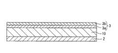
図1は、本発明における多孔質材料の一構成例を示す断面図である。
本実施形態における多孔質材料100は、例えば自動車用内装材として使用され、多孔質基材層1における音源となる車内側(図1における上側)の面に、音が透過可能な通気性層3と表皮層4とが設けられ、多孔質基材層1における車外側(図1における下側)の面に、車内側から車外側への非通気性を確保する非通気性層2が設けられている。
【0015】
ここで、多孔質基材層1は、強化用繊維と、この強化用繊維を相互に点接着する熱可塑性樹脂と、から構成された微細な空隙構造を有している。
強化用繊維は、無機繊維或いは有機繊維のいずれかを単独で使用してもよいし、これらの複合体を使用してもよい。無機繊維としては、例えば、ガラス繊維、炭素繊維、ボロン繊維、ステンレス繊維、 その他の金属繊維などが挙げられ、これら一種を単独で用いても良いし、二種以上で組み合わせて用いてもよい。また、有機繊維としては、例えば、アラミド繊維、ポリエステル繊維、ポリアミド繊維、麻などの天然繊維などが挙げられ、これら一種を単独で用いても良いし、二種以上で組み合わせて用いてもよい。なお、低コストで高い補強効果を得るために、ガラス繊維を用いることがさらに好ましい。
【0016】
この強化用繊維の繊維長さは、補強効果、膨張性、及び賦形性を確保するという点から、5〜30mmが好ましく、さらに好ましくは10〜26mmとするのがよい。また、強化用繊維の直径は、補強効果及び膨張性を確保するという点から、5〜30μmが好ましく、さらに好ましくは10〜25μmとするのがよい。さらに、熱可塑性樹脂との濡れ性や接着性を改良するために、シランカップリング剤などによる処理が施されることが好ましい。
【0017】
熱可塑性樹脂は、多孔質基材層1におけるマトリックスを構成する成分であり、例えば、ポリエチレン、ポリプロピレンなどのポリオレフィン樹脂や、ポリスチレン、ポリ塩化ビニル、ポリエチレンテレフタレート、ポリカーボネート、ポリアミド、ポリアセタールや、ポリアミド共重合体、エチレンー塩化ビニル共重合体、エチレンー酢酸ビニル共重合体、スチレンーブタジエンーアクリロニトリル共重合体などの共重合体や、EPM、EPDMなどの熱可塑性エラストマーを単独或いは二種以上を組み合わせて用いることができる。なお、強度、剛性及び成形性を向上させるために、ポリエチレン、ポリプロピレンなどのポリオレフィン系樹脂が好ましい。この中でも、強度、剛性及び成形性のバランスに優れ、且つ、低コストであるポリプロピレンを用いることがさらに好ましく、具体的には、MFR(測定条件:JISK6758に準拠、210℃、21.6N)が1〜200g/10分の範囲であるポリプロピレンが最適である。ここで、強化用繊維との接着性を向上させるために、不飽和カルボン酸、不飽和カルボン酸無水物などの酸や、エポキシ化合物などの種々の化合物で変性処理を行った熱可塑性樹脂を用いることもできる。例えば、ポリプロピレンを、マレイン酸、無水マレイン酸、アクリル酸などをグラフト共重合することで、分子内に酸無水物基、カルボキシル基などの変性基が形成された熱可塑性樹脂を用いると、強度を向上させることが可能となる。
【0018】
なお、多孔質基材層1における強化用繊維と熱可塑性樹脂との含有割合は、曲げ強度及び曲げ弾性率などの機械的強度の高い多孔質材料を得るために、強化用繊維/熱可塑性樹脂の重量比が、10/90〜70/30の範囲が好ましい。
通気性層3は、多孔質基材層1を構成する熱可塑性樹脂よりも高く、非通気性層2よりも低い融点を有する耐熱用熱可塑性樹脂層3aと、表皮接着用熱可塑性樹脂層3bとを少なくとも積層した多層構造を有しており、多孔質基材層1中に含浸した含浸層Gと、含浸せずに残った通気性層3の残留層Zとによって、表皮接着用熱可塑性樹脂層3bの表面から多孔質基材層1に至る孔Hが複数形成されている。
【0019】
耐熱用熱可塑性樹脂層3aは、多孔質基材層1の形成時や多孔質材料100の形成時において、表皮接着用熱可塑性樹脂層3bが多孔質基材層1に含浸するのを抑制するために積層されており、多孔質基材層1を構成する熱可塑性樹脂よりも高く、非通気性層2よりも低い融点を有する熱可塑性樹脂であれば、上述した多孔質基材層1を構成可能な熱可塑性樹脂を用いることが可能である。例えば、多孔質基材層1を構成する熱可塑性樹脂がポリプロピレンである場合には、この耐熱用熱可塑性樹脂層3aは、例えば、ポリアミド(PA)、ポリアミド(PA)共重合体、ポリエチレンテレフタレート(PET)などで構成することが好ましい。また、耐熱用熱可塑性樹脂層3aの厚みは、通常5μm以上であり、多孔質材料100の形成時に孔Hが形成されやすいように、5〜50μmであることが好ましい。
【0020】
表皮接着用熱可塑性樹脂層3bは、多孔質材料100の形成時において、多孔質基材層1と表皮層4とを接着するために積層されており、少なくとも多孔質材料100の形成時の加熱温度で溶融可能な融点を有するものであれば、いずれの熱可塑性樹脂を用いても構わない。例えば、密度ポリエチレン、直鎖状低密度ポリエチレン、エチレンー酢酸ビニル共重合樹脂、エチレンーエチルアクリレート共重合樹脂、エチレンーアクリル酸共重合樹脂、エチレンーメチルアクリレート共重合樹脂、エチレンーメチルメタクリレート共重合樹脂、エチレンーメタクリル酸共重合樹脂などを単独或いは二種以上の組み合わせたものが挙げられる。
【0021】
この表皮接着用熱可塑性樹脂層3bを構成する熱可塑性樹脂の融点は、90〜140℃であることが望ましい。ここで、90℃以下においては、高温雰囲気中での表皮層4との接着性が低下してしまい、140℃以上においては、冷却プレス成形時に表皮接着用熱可塑性樹脂層3bが固化し、表皮接着強度を確保することが困難となってしまう。また、表皮接着用熱可塑性樹脂層3bの厚みは、通常10μm以上であり、十分な接着性を実現するために、30〜100μmの範囲とすることが望ましい。
【0022】
表皮層4は、通気性を確保でき、通気性層3を構成する表皮接着用熱可塑性樹脂層3bとの接着を可能とする材料であれば、いずれの材料から構成しても構わない。例えば、植物繊維、動物繊維などの天然繊維や、セルロース系、ポリアミド系、ポリエステル系、ポリアクリル系、ポリプロピレン系の合成樹脂繊維などからなる織布或いは不織布が好適に用いられる。また、例えばポリウレタン発泡体のように連続気泡を有する発泡シートを、表皮接着用熱可塑性樹脂層3bと表皮層4との間の面に設けてもよい。発砲シートを設けることで、吸音特性をさらに向上させることが可能となる。
【0023】
非通気性層2は、多孔質材料100の非通気性を確保することで、通気性層3側がフィルタとして機能することを抑制し、表皮層4の汚れを防止するために積層されており、耐熱用熱可塑性樹脂層3aよりも高い融点を有する樹脂であれば、熱可塑性樹脂から構成してもよいし、熱硬化性樹脂から構成しても構わない。この中でも、成形性を向上させるという観点から、熱可塑性樹脂を用いることが好ましく、具体的には、上述した多孔質基材層1を構成可能な熱可塑性樹脂を用いることができる。例えば、多孔質基材層1を構成する熱可塑性樹脂がポリプロピレンで、耐熱用熱可塑性樹脂層3aがポリアミド(PA)共重合体である場合には、非通気性層2をポリアミド、ポリエチレンテレフタレートなどで構成することが望ましい。
【0024】
この非通気性層2の厚みは、非通気性を維持するために、5μm以上が好ましく、さらに好ましくは10〜50μmの範囲とすることが望ましい。
なお、本実施形態における非通気性とは、ASTM(American Society of Test Materials:アメリカ材料試験協会)−D737に準拠して測定された通気度が0cm3/cm2・secのものを指す。
【0025】
ここで、多孔質基材層1と、通気性層3および非通気性層2との接着性を向上させるために、多孔質基材層1と接着する通気性層3および非通気性層2とのそれぞれの間に基材接着樹脂層(図示しない)を設けるようにしても構わない。
基材接着樹脂層は、多孔質基材層1を構成する熱可塑性樹脂と同一或いは類似の構造を有する熱可塑性樹脂によって構成されていることが好ましい。この類似の構造とは、ホモポリマーに対する共重合体やブレンド品、或いはグラフト品などを意味する。特に、多孔質基材層1としてポリプロピレンを用いる場合には、多孔質基材1に対する接着性の観点から、ポリオレフィン系樹脂を用いることが好ましく、より好ましくは、ポリプロピレン、酸変性ポリプロピレンを用いるとよい。
【0026】
また、この基材接着樹脂層のほか、通気性層3および非通気性層2のそれぞれの層間に、別の樹脂層を設けた三層以上の多層構造としても構わない。例えば、このような樹脂層としては、隣接層間をなじませるための仲介層や、内層及び外層をともに溶融することでその流動性を調整するための層などが挙げられ、様々な機能を発現させることが可能となる。
【0027】
なお、通気性層3および非通気性層2に他の樹脂層を積層して多層化を実現させる方法としては、例えば、ドライラミネート法や共押し出し法など、いずれの方法を用いることができる。
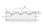
次に、本発明における多孔質材料100の製造方法について、図2〜図3を参照して説明する。
【0028】
まず、強化用繊維と粒状の熱可塑性樹脂とを、空気の微小気泡が分散した界面活性剤水溶液に分散させる。そして、得られた分散液を、多孔性支持体を介して脱水することにより、分散液中の固形分を堆積させ、その堆積物を乾燥して、不織布状のウェブを得る。ここで、このウェブの厚みは、1〜10mmであり、強化用繊維の中に、熱可塑性樹脂の粒子が均一に分散された構成をしている(ウェブ形成工程)。なお、強化用繊維と熱可塑性樹脂は、界面活性剤水溶液などの分散媒を用いずに、乾式で混合しても構わない。
【0029】
次に、このウェブの一方の面に、耐熱用熱可塑性樹脂層3aと、表皮接着用熱可塑性樹脂層3bとを順次積層し、他方の面に、非通気性層2を積層した積層体を形成する。そして、この積層体を、ウェブを構成する熱可塑性樹脂の融点以上、且つ、耐熱用熱可塑性樹脂層3a及び非通気性層2の融点以下の温度で加熱することで熱可塑性樹脂を溶融させたのち、冷却盤間で加圧してシート状に固化し、図2に示すような、緻密なスタンパブルシート10を形成する(スタンパブルシート形成工程)。
【0030】
なお、熱可塑性樹脂がポリプロピレン(融点162℃)で、耐熱性熱可塑性樹脂層3aがナイロン共重合体(融点200℃)で、非通気性層2がナイロン(融点220℃)である場合には、このスタンパブルシート形成工程における加熱温度は170〜200℃、より好ましくは、180〜195℃とするとよい。ここで、200℃以上の温度で加熱してしまうと、耐熱性熱可塑性樹脂層3aを構成するナイロン共重合体が溶融し、最外層である表皮接着用熱可塑性樹脂層3bが多孔質基材層1中に含浸してしまうからである。また、冷却盤間における加圧は、10〜500N/cm2の範囲とすることが望ましい。ここで、500N/cm2を超える圧力を加えると、スタンパブルシート10を構成する強化用繊維の破損を招きやすいからである。さらに、スタンパブルシート10中には、酸化防止剤や対光安定剤、金属不活性化剤、難燃剤、カーボンブラックなどの添加剤・着色剤などを含有させることもできる。これらは、例えば、粒状の熱可塑性樹脂に予め配合したり、コーティングしたりする方法や、ウェブの製造工程中に、スプレーなどで添加する方法などによって含有させることが可能である。
【0031】
次いで、このスタンパブルシート10を、スタンパブルシート10を構成する熱可塑性樹脂、耐熱用熱可塑性樹脂層3a、及び表皮接着用熱可塑性樹脂3bの融点以上、且つ、非通気性層2の融点以下の温度で再加熱することで、スタンパブルシート10を構成する熱可塑性樹脂並びに通気性層3を構成する耐熱用熱可塑性樹脂層3a及び表皮接着用熱可塑性樹脂層3bを溶融させる。すると、スタンパブルシート10は、強化用繊維の拘束が解かれて厚み方向に膨張するとともに、熱可塑性樹脂が強化用繊維どうしを互いに接着した多孔質基材層1となる。また、加熱溶融過程において、通気性層3は熱収縮し、図3に示すように、多孔質基材層1に含浸した含浸層Gと、含浸しないで残留する残留層Zとを形成し、通気性層3の最表面(表皮接着用熱可塑性樹脂3b)から多孔質基材層1に至る複数の孔Hが形成される。そして、複数の孔Hが形成された通気性層3の上面に、表皮層4を積層した後、成形金型内に設置し、金型スペーサの高さやプレスの型締め高さなどを調整した後加圧成形することで、図1に示すように、多孔質基材層1に表皮層4が一体化された多孔質材料100を完成させることができる(多孔質材料形成工程)。
【0032】
なお、熱可塑性樹脂がポリプロピレン(融点162℃)で、耐熱性熱可塑性樹脂がナイロン共重合体(融点200℃)で、非通気性層2がナイロン(融点220℃)である場合には、この多孔質材料形成工程における加熱温度は205〜215℃、より好ましくは、205〜210℃とするとよい。
ここで、スタンパブルシート10の加熱方法としては、熱盤加熱や遠赤外線加熱、近赤外線加熱、通風式加熱などが挙げられ、特に限定されるものではない。また、金型温度は、ウェブを構成する熱可塑性樹脂の凝固点以下であればよく、ハンドリング性や生産性の点から、通常、室温〜60℃の範囲とすることが好ましい。さらに、成形圧力は、製品形状により異なるが、過剰の圧力は強化用繊維を破断させてしまうため、通常は10〜500N/cm2の範囲とすることが好ましい。
【0033】
上記構成の本実施形態における多孔質材料100によれば、多孔質基材層1の音源側となる面に、この多孔質基材層1を構成する熱可塑性樹脂よりも高く、非通気性層2よりも低い融点を有する耐熱用熱可塑性樹脂層3a及び表皮接着用熱可塑性樹脂層3bを少なくとも含む多層構造からなる通気性層3が積層され、この通気性層3には多孔質基材層1に至る複数の孔Hが形成されていることによって、音がこの孔Hを通過し多孔質基材層1に吸音されるようになるため、吸音特性を向上させることが可能となる。
【0034】
また、複数の孔Hが形成された通気性層3の上面に、表皮層4が積層されていることによって、この孔Hの周囲の通気性層3(含浸しないで残留する残留層Z)と表皮層4とが確実に接着されるため、表皮接着性を向上させることが可能となる。
さらに、多孔質基材層1の音源とは反対側の面に、非通気性層2が積層されていることによって、多孔質材料100の音源側から反対側への非通気性が確保できるため、表皮層4の汚れを防止することが可能となる。
【0035】
本発明における多孔質材料100の製造方法によれば、多孔質材料形成工程における加熱温度を、多孔質基材層1の音源側に形成される通気性層3の融点よりも高く、多孔質基材層の音源とは反対側に形成される非通気性層2の融点よりも低い温度とすることによって、通気性層3の一部が溶融・収縮し、通気性層3が多孔質基材層1に含浸した含浸層Gと、含浸しないで残留した残留層Zとを形成するため、通気性層3には複数の孔Hが形成されるようになる。このため、通気性層3が含浸することで形成された孔Hにより、音が多孔質基材層1に吸音され、吸音特性を向上させることが可能となる。
【0036】
また、通気層3が含浸せずに残留した残留層Zと、表皮層4とが確実に接着するようになるため、表皮接着性を向上させることが可能となる。
さらに、多孔質材料100における音源とは反対側の面に、非通気性層2が確実に形成されることによって、音源側から反対側への非通気性が確保されるため、表皮層4の汚れを防止することが可能となる。
【0037】
ここで、本実施形態において、多孔質基材層1となるスタンパブルシート10への通気性層3及び非通気性層2の貼合方法として、予め順次積層しておいた非通気性層2、スタンパブルシート10を形成するウェブ、及び通気性層3を加熱圧縮によって貼合させたが、この貼合方法はこれに限らない。例えば、まず、ウェブのみを加熱圧縮させてスタンパブルシート10を形成したのち、このスタンパブルシート10の両面に通気性層3および非通気性層2を熱融着させる貼合方法を用いても構わない。
【0038】
【実施例】
以下、本実施形態における多孔質材料における吸音特性、表皮接着性、及び剛性を、比較例と比べて確認した結果について説明する。
表1は、実施例及び比較例における多孔質材料に用いた通気性層及び非通気性層の構成材料を示す。なお、実施例及び比較例において、多孔質基材層を構成する熱可塑性樹脂及び強化用繊維と、表皮層の構成材料は、下記に示す同様の条件で行った。
(構成材料)
熱可塑性樹脂:ポリプロピレン粒子(ホモポリプロピレン、融点162℃、MFR65g/10min)
強化用繊維:ガラス繊維、繊維長さ25mm、直径17μm
表皮層:ポリエチレンテレフタレート不織布、目付け量180g/m2、ホットメルト層なし
【0039】
【表1】
<実施例1>
まず、乾燥重量で、ポリプロピレン50%、ガラス繊維50%の割合となるように泡液中で混合分散し、脱泡後乾燥して目付け量700g/m2のウェブを得た。
次に、得られたウェブの両面に、表1に示す構成の通気性層と非通気性層とを積層し積層体を形成する。そして、この積層体をスタンパブルシート形成工程における加熱温度として190℃で加熱した後、25℃の冷却盤間に配置して30N/cm2の圧力でプレス成形し、ガラス繊維とポリプロピレンとが一体的に緻密に固化したスタンパブルシートを得た。
【0041】
次いで、このスタンパブルシートを、多孔質材料形成工程における加熱温度として210℃で加熱したのち、通気性層との貼合面に表皮層を積層し、膨張成形用金型(温度:室温)内に配置し、圧力0.2N/cm2で金型を型閉じして、平板状の多孔質材料を得た。このとき、表皮層が貼合された多孔質基材層の厚みは3.0mmであった。
<実施例2>
実施例1と同様の方法によって、実施例1とは通気性層及び非通気性層の構成材料と、多孔質材料形成工程における加熱温度とを変え、多孔質材料を形成した。ここで、多孔質材料形成工程における加熱温度は、表2に示すように、225℃とした。
<比較例1>
実施例1と同様の方法によって、実施例1とは通気性層と、多孔質材料形成工程における加熱温度とを変え、多孔質材料を形成した。ここで、多孔質材料形成工程における加熱温度は、表2に示すように200℃とした。
<比較例2>
実施例1と同様の構成材料及び方法によって、実施例とは多孔質材料形成工程における加熱温度のみを変え、多孔質材料を形成した。ここで、多孔質材料形成工程における加熱温度は、表2に示すように190℃とした。
【0042】
次に、上記実施例及び比較例によって得られた多孔質材料において、孔形成調査を行うとともに、曲げ試験、常温での表皮剥離強度測定試験、垂直入射吸音率測定試験を行い、多孔質材料の剛性、 表皮接着性、及び吸音特性の評価として表2及び図4に示す。
ここで、孔形成調査は、図1に示す多孔質材料の通気性層及び表皮層をシールし、多孔質基材層の側面から真空吸引を行い、表皮層から煙を通過させた後、表皮層の汚れの有無から孔形成を確認した。結果は表2に示す。
【0043】
また、曲げ試験は、多孔質材料から長さ150mm、 幅50mmの試験片を切り出し、スパン100mm、クロスヘッドスピード50mm/minで表皮層側から荷重をかける三点曲げ試験を実施し、最大荷重及び弾性勾配を23℃で測定した。結果は表2に示す。
さらに、表皮剥離強度測定試験は、多孔質材料から長さ150mm、幅25mmの剥離試験(Tピール試験)片を切り出し、端から50mmの長さで表皮層を多孔質基材層から剥離する。そして、剥離した表皮層と多孔質基材層とをそれぞれチャックに把持させて、180°の方向に引張速度50mm/min、温度23度で、引張試験を行った。結果は表2に示す。
【0044】
さらに、垂直入射吸音率測定試験は、JIS A 1405に準拠して垂直入射吸音率の測定を行った。垂直入射吸音率が1.0のとき、音は完全に吸音されることを示す。結果は図4に示す。
【0045】
【表2】
表2に示すように、スタンパブルシート形成工程における加熱温度よりも低い融点を有する通気性層を一層しか設けなかった比較例1と比べて、スタンパブルシート形成工程における加熱温度よりも高い融点を有する通気層を少なくとも一層以上備えた実施例1、実施例2、比較例2においては、剛性も、表皮接着強度もともに兼ね備えていることが分かる。
【0047】
これは、比較例1のように、スタンパブルシート形成工程における加熱温度(つまり、多孔質基材層の融点よりも高い加熱温度)よりも低い融点を有する通気性層のみで形成すると、スタンパブルシート形成時において通気性層が多孔質基材層中に含浸してしまうため、剛性や表皮接着強度が低下してしまうからである。
【0048】
また、図4に示すように、多孔質材料形成工程における加熱温度を、通気性層を構成する耐熱用熱可塑性樹脂層の融点よりも低い温度とした比較例2と比べて、耐熱用熱可塑性樹脂層の融点よりも高く、非通気性層の融点よりも低い温度とした実施例1、実施例2においては、垂直入射吸音率が良好であるということが分かる。このとき、垂直入射吸音率が良好であった実施例1、実施例2においては、目視による孔形成も確認できた。
【0049】
これは、比較例2において、耐熱用熱可塑性樹脂層の融点よりも低い温度で多孔質材料形成工程を行うと、耐熱用熱可塑性樹脂層が溶解せず、音源となる表皮層側に非通気性層が形成されてしまうため、吸音特性が低下してしまうためであると考えられる。
以上の結果より、通気性層を、少なくとも多孔質基材よりも高い融点を有する材料を含んで構成するとともに、多孔質材料形成工程において通気性層の融点よりも高い温度で加熱するようにしたことによって、音源側の通気層が多孔質基材中に含浸せず、表面に複数の孔が形成されるため、吸音特性及び表皮接着強度をともに向上させていることが確認できた。なお、実施例1及び実施例2と、比較例1及び2との厚み方向の通気度は、いずれも0cm3/cm2・secであった。
【0050】
【発明の効果】
以上説明したように、本発明における多孔質材料によれば、本発明における多孔質材料によれば、多孔質基材層の一方の面に、非通気性層が設けられ、他方の面に、多孔質基材層を構成する熱可塑性樹脂よりも高く、非通気性層よりも低い融点を有する耐熱用熱可塑性樹脂層及び表皮接着用熱可塑性樹脂を少なくとも含む多層構造からなる通気性層と、表皮層とが順次設けられているとともに、通気性層には多孔質基材層に至る複数の孔が形成されていることによって、多孔質材料の積層方向における非通気性を確保できるとともに、吸音特性及び表皮接着性をともに向上させることが可能となる。
【0051】
本発明における多孔質材料の製造方法によれば、多孔質材料の形成工程における加熱温度を、多孔質基材層を構成する熱可塑性樹脂、通気性層を構成する耐熱用熱可塑性樹脂及び表皮接着用熱可塑性樹脂の融点よりも高く、非通気性層の融点よりも低い温度としたことによって、通気性層に多孔質基材層に至る複数の孔が形成されるため、非通気性を確保しつつ、吸音特性及び表皮接着性をともに向上させた多孔質材料を製造することが可能となる。
【図面の簡単な説明】
【図1】本発明における多孔質材料の一構成例を示す断面図である。
【図2】本発明における多孔質材料の一製造過程を示す断面図である。
【図3】本発明における多孔質材料の一製造過程を示す断面図である。
【図4】垂直入射吸音率測定試験の結果を示す図である。
【図5】従来の多孔質材料の一構成例を示す断面図である。
【図6】従来の多孔質材料の他の構成例を示す断面図である。
【符号の説明】
1、11 多孔質基材層
2、21 非通気性層
3 通気性層
3a 耐熱用熱可塑性樹脂
3b 表皮接着用熱可塑性樹脂
4、41 表皮層
10 スタンパブルシート
31 含浸層
32 熱可塑性樹脂層(通気性層)
100、101A、101B 多孔質材料
G 含浸層
Z 残留層
H 孔[0001]
BACKGROUND OF THE INVENTION
The present invention relates to a porous material excellent in sound absorption characteristics and a method for producing the same, and more particularly to a technique effective for further improving sound absorption characteristics, rigidity, and skin adhesion.
[0002]
[Prior art]
In order to reduce the noise in the automobile, a material provided with a sound absorbing function is widely applied to interior materials such as the ceiling. Here, materials used as interior materials for automobiles are desired to have not only excellent sound absorption characteristics but also light weight, excellent rigidity, and good workability. In addition, in the interior material, it has excellent adhesion to the skin layer bonded to the inner surface of the vehicle, and in order to prevent this skin layer from being soiled, it has a structure that ensures air permeability from the vehicle inner side to the vehicle outer side. There is a desire to be.
[0003]
Therefore, in recent years, porous materials comprising expansion fibers of stampable sheets and reinforcing fibers and a thermoplastic resin that adheres them to each other are attracting attention as interior materials for automobiles. Various means for further improving the performance and rigidity have been proposed.
For example, in Japanese Patent Application Laid-Open No. 10-1002909, a melt flow rate (MFR: Melt) is formed on a surface on the sound source side (upper side in FIG. 5) of the porous
[0004]
According to this means, it is possible to prevent the
Further, as means for improving the skin adhesion and rigidity, for example, in Japanese Patent Application Laid-Open No. 2000-15729, the porous material layer 11B shown in FIG. A means is proposed in which a thermoplastic resin layer (for example, MFR = 3 to 50 g / 10 min linear low density polyethylene) 32 having a large MFR is laminated on the surface to be the upper side) through the air-
[0005]
According to this means, the air-
[0006]
[Problem to be Solved by the Invention]
However, in the above-mentioned Japanese Patent Application Laid-Open No. 10-100269, since the impregnation layer 31 impregnated with a thermoplastic resin having a small MFR is formed, the skin adhesion strength between the porous
[0007]
Moreover, in the said Unexamined-Japanese-Patent No. 2000-15729, since the air-
Then, this invention is made | formed in view of the said situation, and makes it a subject to provide the porous material which made it possible to improve both a sound absorption characteristic and skin adhesiveness, and its manufacturing method.
[0008]
[Means for Solving the Problems]
In order to solve such problems, the porous material in the present invention is provided with a non-breathable layer on one surface of a porous base material layer comprising a thermoplastic resin and reinforcing fibers, A breathable layer having a multilayer structure including at least a heat-resistant thermoplastic resin layer having a melting point higher than that of the thermoplastic resin and lower than that of the non-breathable layer and a thermoplastic resin layer for skin adhesion, and a skin And a plurality of pores reaching the porous base material layer are formed in the breathable layer.
[0009]
According to the porous material of the present invention, the heat-resistant side of the porous base material layer having a melting point higher than that of the thermoplastic resin constituting the porous base material layer and lower than that of the air-impermeable layer is provided on the surface on the sound source side. A breathable layer having a multilayer structure including at least a thermoplastic resin layer for use and a thermoplastic resin for skin adhesion is laminated, and a plurality of holes reaching the porous base material layer are formed in this breathable layer. Since sound passes through the holes and is absorbed by the porous base material layer, it is possible to improve sound absorption characteristics.
[0010]
In addition, since the skin layer is laminated on the upper surface of the air permeable layer in which a plurality of holes are formed, the air permeable layer and the skin layer around the hole are securely bonded, so that the skin adhesion is improved. It becomes possible to improve.
Furthermore, since the non-breathable layer is laminated on the surface of the porous base material layer opposite to the sound source, it is possible to ensure the non-breathability from the sound source side to the opposite side of the porous material. It becomes possible to prevent soiling.
[0011]
In the method for producing a porous material according to the present invention, a non-breathable layer is provided on one side of a stampable sheet comprising a thermoplastic resin and reinforcing fibers, and the other side is made of the thermoplastic resin. A stampable sheet provided with a breathable layer having a multilayer structure including at least a heat-resistant thermoplastic resin layer having a melting point lower than that of the non-breathable layer and a thermoplastic resin layer for skin adhesion. The breathable layer is heated and melted by heating at a temperature higher than the melting point of the plastic resin, the heat-resistant thermoplastic resin layer, and the skin-adhesive thermoplastic resin layer, and lower than the melting point of the non-breathable layer. A plurality of holes extending from the surface of the breathable layer to the porous base material layer are formed, and a skin layer is bonded.
[0012]
According to the method for producing a porous material in the present invention, a stampable sheet in which a non-breathable layer and a breathable layer are formed on both sides is used as a thermoplastic resin, a heat-resistant thermoplastic resin layer, and a skin-bonding thermoplastic resin layer. By heating at a temperature that is higher than the melting point of the non-breathable layer and lower than the melting point of the non-breathable layer, both the heat-resistant thermoplastic resin layer and the skin-bonding thermoplastic resin layer that are breathable layers are melted, and a plurality of pores are formed. It is formed. For this reason, sound is reliably absorbed by the holes formed in the air-permeable layer, and is securely adhered to the skin by the air-permeable layer around the holes. Therefore, it is possible to provide a porous material with improved sound absorption characteristics and skin adhesion.
[0013]
In addition, by heating at a temperature lower than the melting point of the non-breathable layer, the non-breathable layer is laminated on the side opposite to the skin layer that is the sound source side of the porous material, so from the sound source side of the porous material It is possible to provide a porous material that can ensure air permeability to the opposite side and prevent the skin layer from being soiled.
[0014]
DETAILED DESCRIPTION OF THE INVENTION
Hereinafter, an embodiment of the present invention will be described with reference to the drawings.
FIG. 1 is a cross-sectional view showing a structural example of a porous material according to the present invention.
The
[0015]
Here, the porous
As the reinforcing fiber, either an inorganic fiber or an organic fiber may be used alone, or a composite of these may be used. Examples of the inorganic fiber include glass fiber, carbon fiber, boron fiber, stainless steel fiber, and other metal fibers. One kind of these may be used alone, or two or more kinds may be used in combination. Examples of the organic fibers include natural fibers such as aramid fibers, polyester fibers, polyamide fibers, and hemp, and these may be used alone or in combination of two or more. In order to obtain a high reinforcing effect at low cost, it is more preferable to use glass fiber.
[0016]
The fiber length of the reinforcing fiber is preferably 5 to 30 mm, more preferably 10 to 26 mm, from the viewpoint of securing a reinforcing effect, expandability, and shapeability. Further, the diameter of the reinforcing fiber is preferably 5 to 30 μm, more preferably 10 to 25 μm, from the viewpoint of securing a reinforcing effect and expandability. Furthermore, in order to improve wettability and adhesiveness with a thermoplastic resin, it is preferable to perform a treatment with a silane coupling agent or the like.
[0017]
The thermoplastic resin is a component constituting the matrix in the porous
[0018]
The content ratio of the reinforcing fiber and the thermoplastic resin in the
The
[0019]
The heat-resistant
[0020]
The
[0021]
The melting point of the thermoplastic resin constituting the
[0022]
The skin layer 4 may be made of any material as long as the material can ensure air permeability and can be adhered to the skin adhesive
[0023]
The
[0024]
The thickness of the air-
In addition, the non-breathability in this embodiment means that the air permeability measured in accordance with ASTM (American Society of Test Materials) -D737 is 0 cm.Three / Cm2 ・ This refers to sec.
[0025]
Here, in order to improve the adhesion between the
The base material adhesive resin layer is preferably made of a thermoplastic resin having the same or similar structure as the thermoplastic resin constituting the porous
[0026]
In addition to the base material adhesive resin layer, a multilayer structure of three or more layers in which another resin layer is provided between each of the air-
[0027]
In addition, as a method of laminating another resin layer on the air-
Next, the manufacturing method of the
[0028]
First, the reinforcing fibers and the granular thermoplastic resin are dispersed in a surfactant aqueous solution in which fine air bubbles are dispersed. Then, the obtained dispersion is dehydrated through the porous support to deposit the solid content in the dispersion, and the deposit is dried to obtain a nonwoven web. Here, the thickness of the web is 1 to 10 mm, and the thermoplastic resin particles are uniformly dispersed in the reinforcing fibers (web forming step). The reinforcing fiber and the thermoplastic resin may be mixed in a dry manner without using a dispersion medium such as an aqueous surfactant solution.
[0029]
Next, a laminated body in which the heat-resistant
[0030]
When the thermoplastic resin is polypropylene (melting point: 162 ° C.), the heat-resistant
[0031]
Next, the
[0032]
When the thermoplastic resin is polypropylene (melting point 162 ° C.), the heat-resistant thermoplastic resin is nylon copolymer (melting point 200 ° C.), and the air-
Here, the heating method of the
[0033]
According to the
[0034]
Further, the skin layer 4 is laminated on the upper surface of the air-
Further, since the
[0035]
According to the method for manufacturing the
[0036]
Further, since the residual layer Z remaining without being impregnated by the air-
Furthermore, since the air-
[0037]
Here, in this embodiment, as a method for bonding the air-
[0038]
【Example】
Hereinafter, the results of confirming the sound absorption characteristics, skin adhesion, and rigidity of the porous material according to the present embodiment as compared with the comparative example will be described.
Table 1 shows the constituent materials of the breathable layer and the non-breathable layer used for the porous materials in Examples and Comparative Examples. In Examples and Comparative Examples, the thermoplastic resin and reinforcing fibers constituting the porous base material layer and the constituent material of the skin layer were performed under the same conditions as described below.
(Constituent materials)
Thermoplastic resin: polypropylene particles (homopolypropylene, melting point 162 ° C., MFR 65 g / 10 min)
Reinforcing fiber: glass fiber, fiber length 25 mm, diameter 17 μm
Skin layer: Polyethylene terephthalate nonwoven fabric, basis weight 180 g / m2 Without hot melt layer
[0039]
[Table 1]
<Example 1>
First, it is mixed and dispersed in a foam liquid so as to have a ratio of 50% polypropylene and 50% glass fiber by dry weight, and after drying, it is dried to a basis weight of 700 g / m2 Got the web.
Next, a breathable layer and a non-breathable layer having the structure shown in Table 1 are laminated on both surfaces of the obtained web to form a laminate. And after heating this laminated body at 190 degreeC as a heating temperature in a stampable sheet formation process, it arrange | positions between 25 degreeC cooling boards, and is 30 N / cm2 A stampable sheet in which glass fiber and polypropylene were solidified in an integrated manner was obtained.
[0041]
Next, this stampable sheet is heated at 210 ° C. as the heating temperature in the porous material forming step, and then a skin layer is laminated on the bonding surface with the breathable layer, and inside the expansion mold (temperature: room temperature) At a pressure of 0.2 N / cm2 The mold was closed with a flat plate-like porous material. At this time, the thickness of the porous base material layer to which the skin layer was bonded was 3.0 mm.
<Example 2>
By the same method as in Example 1, the porous material was formed by changing the constituent materials of the breathable layer and the non-breathable layer and the heating temperature in the porous material forming step. Here, the heating temperature in the porous material forming step was 225 ° C. as shown in Table 2.
<Comparative Example 1>
By the same method as in Example 1, the porous material was formed by changing the breathable layer and the heating temperature in the porous material forming step from Example 1. Here, the heating temperature in the porous material forming step was set to 200 ° C. as shown in Table 2.
<Comparative example 2>
By the same constituent materials and methods as in Example 1, only the heating temperature in the porous material forming step was changed from that in Example, and a porous material was formed. Here, the heating temperature in the porous material forming step was set to 190 ° C. as shown in Table 2.
[0042]
Next, in the porous materials obtained by the above examples and comparative examples, while conducting pore formation investigation, bending test, skin peel strength measurement test at normal temperature, normal incidence sound absorption coefficient measurement test, Table 2 and FIG. 4 show the evaluation of rigidity, skin adhesion, and sound absorption characteristics.
Here, in the pore formation investigation, the breathable layer and the skin layer of the porous material shown in FIG. 1 are sealed, vacuum suction is performed from the side surface of the porous base material layer, and smoke is passed through the skin layer. Hole formation was confirmed from the presence or absence of contamination of the layer. The results are shown in Table 2.
[0043]
In addition, the bending test is a three-point bending test in which a test piece having a length of 150 mm and a width of 50 mm is cut out from a porous material and a load is applied from the skin layer side at a span of 100 mm and a crosshead speed of 50 mm / min. The elastic gradient was measured at 23 ° C. The results are shown in Table 2.
Further, in the skin peel strength measurement test, a peel test (T peel test) piece having a length of 150 mm and a width of 25 mm is cut out from the porous material, and the skin layer is peeled from the porous base material layer at a length of 50 mm from the end. The peeled skin layer and porous substrate layer were each held by a chuck, and a tensile test was performed in a 180 ° direction at a tensile speed of 50 mm / min and a temperature of 23 degrees. The results are shown in Table 2.
[0044]
Further, in the normal incident sound absorption coefficient measurement test, the normal incident sound absorption coefficient was measured according to JIS A 1405. When the normal incident sound absorption coefficient is 1.0, the sound is completely absorbed. The results are shown in FIG.
[0045]
[Table 2]
As shown in Table 2, compared with Comparative Example 1 in which only one breathable layer having a melting point lower than the heating temperature in the stampable sheet forming step was provided, the melting point higher than the heating temperature in the stampable sheet forming step. It can be seen that in Example 1, Example 2, and Comparative Example 2 having at least one air-permeable layer having both the rigidity and the skin adhesion strength.
[0047]
This is because, as in Comparative Example 1, when only a breathable layer having a melting point lower than the heating temperature in the stampable sheet forming step (that is, the heating temperature higher than the melting point of the porous base material layer) is used, the stampable This is because the air permeability layer impregnates the porous base material layer when forming the sheet, so that the rigidity and the skin adhesion strength are lowered.
[0048]
Moreover, as shown in FIG. 4, compared with the comparative example 2 which made the heating temperature in a porous material formation process the temperature lower than melting | fusing point of the heat-resistant thermoplastic resin layer which comprises a breathable layer, heat-resistant thermoplasticity In Example 1 and Example 2 in which the temperature is higher than the melting point of the resin layer and lower than the melting point of the air-impermeable layer, it can be seen that the normal incident sound absorption coefficient is good. At this time, in Example 1 and Example 2 in which the normal incident sound absorption coefficient was good, the formation of holes by visual observation was also confirmed.
[0049]
This is because, in Comparative Example 2, when the porous material forming step is performed at a temperature lower than the melting point of the heat-resistant thermoplastic resin layer, the heat-resistant thermoplastic resin layer is not dissolved, and the skin layer serving as a sound source is not vented. This is considered to be because the sound-absorbing property is deteriorated because the conductive layer is formed.
From the above results, the breathable layer is configured to include at least a material having a melting point higher than that of the porous base material, and is heated at a temperature higher than the melting point of the breathable layer in the porous material forming step. As a result, the sound source side ventilation layer was not impregnated in the porous base material, and a plurality of pores were formed on the surface, so that it was confirmed that both the sound absorption characteristics and the skin adhesion strength were improved. The air permeability in the thickness direction of each of Examples 1 and 2 and Comparative Examples 1 and 2 is 0 cm.Three / Cm2 ・ It was sec.
[0050]
【The invention's effect】
As described above, according to the porous material of the present invention, according to the porous material of the present invention, the non-breathable layer is provided on one surface of the porous base material layer, and the other surface, A breathable layer having a multilayer structure including at least a heat-resistant thermoplastic resin layer having a melting point higher than that of the thermoplastic resin constituting the porous base material layer and lower than that of the non-breathable layer, and a skin-bonding thermoplastic resin; The skin layer is sequentially provided, and the air permeable layer is formed with a plurality of holes reaching the porous base material layer, so that air permeability in the stacking direction of the porous material can be secured and sound absorption It is possible to improve both the properties and the skin adhesion.
[0051]
According to the method for producing a porous material in the present invention, the heating temperature in the porous material forming step is set such that the thermoplastic resin constituting the porous base material layer, the heat-resistant thermoplastic resin constituting the breathable layer, and the skin adhesion. By making the temperature higher than the melting point of the thermoplastic resin for use and lower than the melting point of the non-breathable layer, a plurality of holes reaching the porous base material layer are formed in the breathable layer, ensuring non-breathability However, it is possible to produce a porous material with improved sound absorption characteristics and skin adhesion.
[Brief description of the drawings]
FIG. 1 is a cross-sectional view showing a structural example of a porous material according to the present invention.
FIG. 2 is a cross-sectional view showing one manufacturing process of a porous material according to the present invention.
FIG. 3 is a cross-sectional view showing one manufacturing process of a porous material according to the present invention.
FIG. 4 is a diagram showing the results of a normal incidence sound absorption coefficient measurement test.
FIG. 5 is a cross-sectional view showing a structural example of a conventional porous material.
FIG. 6 is a cross-sectional view showing another configuration example of a conventional porous material.
[Explanation of symbols]
1,11 Porous base material layer
2, 21 Non-breathable layer
3 Breathable layer
3a Thermoplastic resin for heat resistance
3b Thermoplastic resin for skin adhesion
4, 41 Skin layer
10 Stampable seat
31 Impregnated layer
32 Thermoplastic resin layer (breathable layer)
100, 101A, 101B Porous material
G impregnation layer
Z residual layer
H hole
Claims (2)
Translated fromJapanese前記通気性層には、前記多孔質基材層に至る複数の孔が形成されていることを特徴とする多孔質材料。A non-breathable layer is provided on one surface of a porous base material layer comprising a thermoplastic resin and reinforcing fibers, and the other surface is higher than the thermoplastic resin and more than the non-breathable layer. A breathable layer having a multilayer structure including at least a heat-resistant thermoplastic resin layer having a low melting point and a thermoplastic resin layer for skin adhesion, and a skin layer are sequentially provided,
A porous material, wherein the breathable layer has a plurality of pores reaching the porous substrate layer.
Priority Applications (1)
| Application Number | Priority Date | Filing Date | Title |
|---|---|---|---|
| JP2002024461AJP3730177B2 (en) | 2002-01-31 | 2002-01-31 | Porous material and method for producing the same |
Applications Claiming Priority (1)
| Application Number | Priority Date | Filing Date | Title |
|---|---|---|---|
| JP2002024461AJP3730177B2 (en) | 2002-01-31 | 2002-01-31 | Porous material and method for producing the same |
Publications (2)
| Publication Number | Publication Date |
|---|---|
| JP2003225959A JP2003225959A (en) | 2003-08-12 |
| JP3730177B2true JP3730177B2 (en) | 2005-12-21 |
Family
ID=27746900
Family Applications (1)
| Application Number | Title | Priority Date | Filing Date |
|---|---|---|---|
| JP2002024461AExpired - Fee RelatedJP3730177B2 (en) | 2002-01-31 | 2002-01-31 | Porous material and method for producing the same |
Country Status (1)
| Country | Link |
|---|---|
| JP (1) | JP3730177B2 (en) |
Families Citing this family (3)
| Publication number | Priority date | Publication date | Assignee | Title |
|---|---|---|---|---|
| JP4702828B2 (en)* | 2004-01-20 | 2011-06-15 | 株式会社竹中工務店 | Antibacterial air duct |
| KR101062679B1 (en) | 2007-12-05 | 2011-09-06 | 코오롱인더스트리 주식회사 | Artificial leather and its manufacturing method |
| US11186236B2 (en) | 2016-02-19 | 2021-11-30 | Suminoe Textile Co., Ltd. | Sheet for interior or exterior materials for automobiles and method for producing same |
- 2002
- 2002-01-31JPJP2002024461Apatent/JP3730177B2/ennot_activeExpired - Fee Related
Also Published As
| Publication number | Publication date |
|---|---|
| JP2003225959A (en) | 2003-08-12 |
Similar Documents
| Publication | Publication Date | Title |
|---|---|---|
| CN1954126B (en) | Decorative interior sound absorbing panel | |
| US12053969B2 (en) | Method of producing automotive interior articles including frims | |
| US20220161516A1 (en) | Prepregs, cores and composite articles including powder coated layers | |
| KR102507982B1 (en) | Acoustic prepregs, cores and composite articles and methods of use thereof | |
| EP0758577B1 (en) | Stampable sheet made by papermaking technique and method for manufacturing lightweight molded stampable sheet | |
| JP2021008119A (en) | Composite product with film with tie layer | |
| JP2018522755A (en) | Underbody shield composition, articles with improved peel strength, and methods of use thereof | |
| JP4381941B2 (en) | Laminate for automotive interior ceiling materials | |
| US20200290310A1 (en) | Lightweight reinforced thermoplastic composite articles including bicomponent fibers | |
| KR100949783B1 (en) | Headliner of having a height acoustic-absorptivity for vehicle | |
| JP3730177B2 (en) | Porous material and method for producing the same | |
| JPH079632A (en) | Molded composite and production thereof | |
| US6756099B2 (en) | Laminated resin material | |
| JP3773044B2 (en) | Porous material | |
| JP2004122545A (en) | Thermoformable core material and interior finish material for car using the core material | |
| JP3654821B2 (en) | Thermoformable core material and manufacturing method thereof | |
| JP6751278B1 (en) | Laminated sound absorbing material | |
| JP3574209B2 (en) | Lightweight stampable sheet skin bonded product | |
| JP3853077B2 (en) | Dispersion method stampable sheet expansion molded body and dispersion method stampable sheet | |
| JP2000015729A (en) | Dispersion stampable sheet and expanded molded product thereof | |
| AU2020214836A1 (en) | Lightweight reinforced thermoplastic composite articles including bicomponent fibers | |
| JP2005186334A (en) | Porous stampable sheet, its manufacturing method, expanded molded product of porous stampable sheet and its manufacturing method | |
| KR102280425B1 (en) | Porous fiber reinforced composite material and method of preparing the same | |
| JP2872896B2 (en) | Thermoformable core material, production method thereof and interior material | |
| JP3095503B2 (en) | Thermoformable core material and method for producing the same |
Legal Events
| Date | Code | Title | Description |
|---|---|---|---|
| A621 | Written request for application examination | Free format text:JAPANESE INTERMEDIATE CODE: A621 Effective date:20040414 | |
| A977 | Report on retrieval | Free format text:JAPANESE INTERMEDIATE CODE: A971007 Effective date:20050901 | |
| TRDD | Decision of grant or rejection written | ||
| A01 | Written decision to grant a patent or to grant a registration (utility model) | Free format text:JAPANESE INTERMEDIATE CODE: A01 Effective date:20050920 | |
| A61 | First payment of annual fees (during grant procedure) | Free format text:JAPANESE INTERMEDIATE CODE: A61 Effective date:20051005 | |
| R150 | Certificate of patent or registration of utility model | Free format text:JAPANESE INTERMEDIATE CODE: R150 | |
| FPAY | Renewal fee payment (event date is renewal date of database) | Free format text:PAYMENT UNTIL: 20081014 Year of fee payment:3 | |
| FPAY | Renewal fee payment (event date is renewal date of database) | Free format text:PAYMENT UNTIL: 20091014 Year of fee payment:4 | |
| FPAY | Renewal fee payment (event date is renewal date of database) | Free format text:PAYMENT UNTIL: 20091014 Year of fee payment:4 | |
| FPAY | Renewal fee payment (event date is renewal date of database) | Free format text:PAYMENT UNTIL: 20101014 Year of fee payment:5 | |
| FPAY | Renewal fee payment (event date is renewal date of database) | Free format text:PAYMENT UNTIL: 20111014 Year of fee payment:6 | |
| LAPS | Cancellation because of no payment of annual fees |