JP3729807B2 - Sample transport holder transfer system - Google Patents
Sample transport holder transfer systemDownload PDFInfo
- Publication number
- JP3729807B2 JP3729807B2JP2002378598AJP2002378598AJP3729807B2JP 3729807 B2JP3729807 B2JP 3729807B2JP 2002378598 AJP2002378598 AJP 2002378598AJP 2002378598 AJP2002378598 AJP 2002378598AJP 3729807 B2JP3729807 B2JP 3729807B2
- Authority
- JP
- Japan
- Prior art keywords
- holder
- holding mechanism
- sample transport
- sample
- transport
- Prior art date
- Legal status (The legal status is an assumption and is not a legal conclusion. Google has not performed a legal analysis and makes no representation as to the accuracy of the status listed.)
- Expired - Lifetime
Links
- 238000012546transferMethods0.000titleclaimsdescription70
- 230000007246mechanismEffects0.000claimsdescription68
- 239000000758substrateSubstances0.000claimsdescription2
- 230000002093peripheral effectEffects0.000description6
- 230000003028elevating effectEffects0.000description5
- 230000000694effectsEffects0.000description3
- 238000012423maintenanceMethods0.000description3
- 238000012986modificationMethods0.000description2
- 230000004048modificationEffects0.000description2
- 239000000725suspensionSubstances0.000description2
- 238000012360testing methodMethods0.000description2
- 239000008280bloodSubstances0.000description1
- 210000004369bloodAnatomy0.000description1
- 238000010586diagramMethods0.000description1
- 238000012545processingMethods0.000description1
- 210000002700urineAnatomy0.000description1
Images
Classifications
- G—PHYSICS
- G01—MEASURING; TESTING
- G01N—INVESTIGATING OR ANALYSING MATERIALS BY DETERMINING THEIR CHEMICAL OR PHYSICAL PROPERTIES
- G01N35/00—Automatic analysis not limited to methods or materials provided for in any single one of groups G01N1/00 - G01N33/00; Handling materials therefor
- G01N35/02—Automatic analysis not limited to methods or materials provided for in any single one of groups G01N1/00 - G01N33/00; Handling materials therefor using a plurality of sample containers moved by a conveyor system past one or more treatment or analysis stations
- G01N35/04—Details of the conveyor system
- G—PHYSICS
- G01—MEASURING; TESTING
- G01N—INVESTIGATING OR ANALYSING MATERIALS BY DETERMINING THEIR CHEMICAL OR PHYSICAL PROPERTIES
- G01N35/00—Automatic analysis not limited to methods or materials provided for in any single one of groups G01N1/00 - G01N33/00; Handling materials therefor
- G01N35/02—Automatic analysis not limited to methods or materials provided for in any single one of groups G01N1/00 - G01N33/00; Handling materials therefor using a plurality of sample containers moved by a conveyor system past one or more treatment or analysis stations
- G01N35/04—Details of the conveyor system
- G01N2035/0401—Sample carriers, cuvettes or reaction vessels
- G01N2035/0406—Individual bottles or tubes
- G—PHYSICS
- G01—MEASURING; TESTING
- G01N—INVESTIGATING OR ANALYSING MATERIALS BY DETERMINING THEIR CHEMICAL OR PHYSICAL PROPERTIES
- G01N35/00—Automatic analysis not limited to methods or materials provided for in any single one of groups G01N1/00 - G01N33/00; Handling materials therefor
- G01N35/02—Automatic analysis not limited to methods or materials provided for in any single one of groups G01N1/00 - G01N33/00; Handling materials therefor using a plurality of sample containers moved by a conveyor system past one or more treatment or analysis stations
- G01N35/04—Details of the conveyor system
- G01N2035/046—General conveyor features
- G01N2035/0465—Loading or unloading the conveyor
- G—PHYSICS
- G01—MEASURING; TESTING
- G01N—INVESTIGATING OR ANALYSING MATERIALS BY DETERMINING THEIR CHEMICAL OR PHYSICAL PROPERTIES
- G01N35/00—Automatic analysis not limited to methods or materials provided for in any single one of groups G01N1/00 - G01N33/00; Handling materials therefor
- G01N35/02—Automatic analysis not limited to methods or materials provided for in any single one of groups G01N1/00 - G01N33/00; Handling materials therefor using a plurality of sample containers moved by a conveyor system past one or more treatment or analysis stations
- G01N35/04—Details of the conveyor system
- G01N2035/046—General conveyor features
- G01N2035/0467—Switching points ("aiguillages")
- G—PHYSICS
- G01—MEASURING; TESTING
- G01N—INVESTIGATING OR ANALYSING MATERIALS BY DETERMINING THEIR CHEMICAL OR PHYSICAL PROPERTIES
- G01N35/00—Automatic analysis not limited to methods or materials provided for in any single one of groups G01N1/00 - G01N33/00; Handling materials therefor
- G01N35/02—Automatic analysis not limited to methods or materials provided for in any single one of groups G01N1/00 - G01N33/00; Handling materials therefor using a plurality of sample containers moved by a conveyor system past one or more treatment or analysis stations
- G01N35/04—Details of the conveyor system
- G01N2035/0474—Details of actuating means for conveyors or pipettes
- G01N2035/0482—Transmission
- G01N2035/0484—Belt or chain
- G—PHYSICS
- G01—MEASURING; TESTING
- G01N—INVESTIGATING OR ANALYSING MATERIALS BY DETERMINING THEIR CHEMICAL OR PHYSICAL PROPERTIES
- G01N35/00—Automatic analysis not limited to methods or materials provided for in any single one of groups G01N1/00 - G01N33/00; Handling materials therefor
- G01N35/10—Devices for transferring samples or any liquids to, in, or from, the analysis apparatus, e.g. suction devices, injection devices
- G01N2035/1027—General features of the devices
- G01N2035/1048—General features of the devices using the transfer device for another function
- G01N2035/1051—General features of the devices using the transfer device for another function for transporting containers, e.g. retained by friction
Landscapes
- Physics & Mathematics (AREA)
- Health & Medical Sciences (AREA)
- Life Sciences & Earth Sciences (AREA)
- Chemical & Material Sciences (AREA)
- Analytical Chemistry (AREA)
- Biochemistry (AREA)
- General Health & Medical Sciences (AREA)
- General Physics & Mathematics (AREA)
- Immunology (AREA)
- Pathology (AREA)
- Automatic Analysis And Handling Materials Therefor (AREA)
- Sampling And Sample Adjustment (AREA)
Description
Translated fromJapanese【0001】
【発明の属する技術分野】
本発明は、ガイドレール付きのベルトコンベアによって搬送可能な如く設けられた検体搬送ホルダーを、一方のベルトコンベアから他方のベルトコンベアに移し変える検体搬送ホルダー移載システムに関する。
【0002】
【従来の技術】
血液や尿などの検体を入れた所謂試験管などを含むチューブ形検体容器を搬送する場合、上記検体容器は検体搬送ホルダーによって保持された状態で搬送される。
【0003】
最も一般的な検体搬送ホルダーとして、いわゆる円柱状ラックがある。この円柱状ラックは、円柱状基体の軸心部に設けた収容部に、チューブ形検体容器を収容し、外周部に設けた環状溝またはリングをベルトコンベアのガイドレールに対して係合させ、チューブ形検体容器を一本づつベルトコンベアで搬送し得るものとなっている。
【0004】
この円柱状ラックタイプの検体搬送ホルダーを用いれば、各チューブ形検体容器をそれぞれ独立して所定の場所へ搬送可能である。しかしその搬送範囲は、同一のベルトコンベアによる搬送範囲内に限られる。
【0005】
従来、複数のベルトコンベアを備えた検体処理システムにおいて、検体容器を一方のベルトコンベア(正搬送レーン)から他方のベルトコンベア(副搬送レーン)へ移載する場合に、移動アーム(ロボット)を用いて一方のベルトコンベアにある検体搬送ホルダーから検体容器のみを抜き取り、これを他方のベルトコンベアにある検体搬送ホルダーに移し変えるように構成されたものがある(特許文献1参照)。
【0006】
【特許文献1】
特開2001−124786公報(段落[0022]、図1)
【0007】
【発明が解決しようとする課題】
上記公報に開示されている技術的手段では、検体容器を移し変える場合、一方の検体搬送ホルダーに保持されているチューブ形検体容器を、他方の検体搬送ホルダーに一本づつ移し変えなければならない。従って極めて非能率的である。又、一方のベルトコンベアには検体容器を引き抜かれた後の検体搬送ホルダーのみが残り、他方のベルトコンベアには空の検体搬送ホルダーを予め待機させておかねばならない。したがって周辺整備作業を含めた移し変え作業全体が非常に煩雑なものとなる。
【0008】
本発明は、上記事情を考慮してなされたものであり、その目的は下記のような利点を有する検体搬送ホルダー移載システムを提供することにある。
【0009】
a.検体容器を一方のベルトコンベアから他方のベルトコンベアへ能率よく移載可能である。
【0010】
b.移し変え作業は容易である。
【0011】
【課題を解決するための手段】
上記課題を解決し目的を達成するために、本発明の検体搬送ホルダー移載システムは、下記のような特徴ある構成を有している。なお下記以外の特徴ある構成については実施形態の中で明らかにする。
【0012】
本発明の検体搬送ホルダー移載システムは、検体を垂直に収容保持する円柱状基体6の外周部に上下に離間する二つのフランジ7,7を有するとともに、前記二つのフランジ7,7間に環状溝8を有する検体搬送ホルダー1の移載システムにおいて、
前記検体搬送ホルダー1を一列に搬送可能な如く前記環状溝8に係合するガイド片11a、12aを有する一対の平行なガイドレール11,12を備えた並行する複数のベルトコンベア10A,10Bと、
これら複数のベルトコンベア10A,10Bのうち、少なくとも二つのコンベア10A,10Bにおける長手方向の特定位置に対応して設けられ、前記ガイド片11a、12aを含む一対のガイドレール11,12が部分的に取り除かれた態様をなすホルダー移載エリアEa,Efと、
このホルダー移載エリアEa,Efに対して着脱自在に装填セット可能な如く設けられ、一端側にホルダー搬入口V、他端側にホルダー搬出口Wを有するホルダー保持機構20と、
このホルダー保持機構20に設けられ、下端部に前記部分的に取り除かれた前記ガイド片11a、12aを含む一対のガイドレール11,12の代替機能を備え、前記検体搬送ホルダー1の環状溝8と係合するガイドレール部片21,22と検体搬送ホルダー1の基体6側面と対向する一対の平行なガイドレール板21a,22aを備え、前記ホルダー移載エリアEa,Efに対して装填セットされたとき、前記ガイドレール部片21,22が前記ガイド片11a、12aと前記ガイドレール板21a,22aが前記ガイドレール11,12とそれぞれ同一平面上に位置して前記検体搬送ホルダー1を前記ホルダー搬入口Vから前記ホルダー搬出口Wにガイドするホルダーガイド部材23aと、
前記ホルダー保持機構20を吊持して上下動及び横移動し、前記ホルダー移載エリアEa,Efが形成されているコンベア間の移動操作及び上記ホルダー移載エリアEa,Efに対する着脱操作を行なう移動機構30と、
この移動機構30を前記検体搬送ホルダー1の搬送制御と関連付けて駆動制御するコントローラー40と、を備えたことを特徴としている。
【0013】
上記検体搬送ホルダー移載システムにおいては、検体容器の行き先変更あるいは迂回を要する場合、検体容器を収容保持した複数の検体搬送ホルダーを、ホルダーごと一方のベルトコンベアから他方のベルトコンベアへ移載することができる。このため検体容器を極めて能率よく他のコンベアへ移載することが可能である。しかも空の検体搬送ホルダーを、予め用意するといった周辺整備作業を一切要さないので、移し変え作業は極めて容易である。
【0014】
【発明の実施の形態】
(第一実施形態)
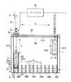
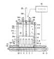
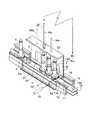
図1は、本発明の第一実施形態に係る検体搬送ホルダー移載システムの構成を示す正面図である。図2は図1のZーZ線矢視断面図である。図3は上記検体搬送ホルダー移載システムの主要部の構成を示す斜視図である。
【0015】
図1〜図3に示すように、並行配設されている複数のベルトコンベア10A,10B,〜は、いずれも円柱状ラックと呼ばれる検体搬送ホルダー1,2,〜を所定方向へ搬送可能な如く設けられている。すなわちベルトコンベア10A,10B,〜の各々は、両側に一対の平行なガイドレール11,12を対設した支持フレーム13,14を有している。上記支持フレーム13,14の下方部位には、モーター15で回転移送される搬送用無端ベルト16が配置されている。
【0016】
上記検体搬送ホルダー1,2,〜は、円柱状基体の軸心部に設けた収容部に、チューブ形検体容器(試験管)Tを垂直に収容保持し得るものとなっている。上記円柱状基体6の外周部には、二つのフランジ7,7が所定間隔で配設されている。二つのフランジ7,7間に存在する環状溝8は、検体搬送ホルダー1,2,〜が前記搬送用無端ベルト16上に載置されたとき、前記一対の平行なガイドレール11,12のガイド片11a,12aに対して係合する。これによって搬送時における振動で検体搬送ホルダー1,2,〜が転倒するのを防止できる。
【0017】
かくして検体搬送ホルダー1,2,〜を、例えばベルトコンベア10Aの無端ベルト16上に載せ、各環状溝を一対のガイドレール11,12に係合させた状態でモーター15を回転させると、検体搬送ホルダー1,2,〜は、無端ベルト16の回転移送に伴って所定方向へ安定に搬送される。
【0018】
前記複数のベルトコンベア10A,10B,〜のうち、少なくとも二つのコンベア、例えば10Aと10Fにおける長手方向の特定箇所には、ホルダー移載エリアEa,Ef(不図示)が対応して設けられている。このホルダー移載エリアEa,Efは、各一対のガイドレール11,12を含む支持フレーム13,14の対応箇所を部分的に取り除いた態様をなしている。
【0019】
上記ホルダー移載エリアEa,Efに対し、ホルダー保持機構20が着脱自在に装填セットし得るものとなっている。このホルダー保持機構20は、全体が縦長のコの字形をなすホルダーガイド部材23aのフレーム23を主体として形成されている。フレーム23の下端部には、前記部分的に取り除かれたガイドレール11,12の代替機能を持ち、検体搬送ホルダー1,2,〜の環状溝8に係合する一対の平行なガイドレール部片21,22を有するガイドレール板21a,22aが対設されている。このガイドレール部片21,22を有するガイドレール板21a,22aの一端側がホルダー搬入口Vとなっており、他端側がホルダー搬出口Wとなっている。
【0020】
ホルダー保持機構20は移動機構30により移動操作される。この移動機構30は、前記ホルダー保持機構20を吊持し、かつ前記ホルダー移載エリアEa,Efが形成されているコンベア10Aと10Fとの間の移動操作及び上記ホルダー移載エリアEa,Efに対する着脱操作を行なう。
【0021】
すなわち移動機構30は、前記複数のベルトコンベア10A,10B,〜を跨ぐ形で設置された垂直支持部材31V及び水平支持部材31Hからなる架体31の水平支持部材31Hに沿って、移動体32が矢印Xで示す水平方向に移動可能となっている。この移動体32には、昇降機構33と一対のガイド機構34,35が取付けられている。昇降機構33は、下端が前記ホルダー保持機構20のフレーム23の上側壁センターに結合している吊り下げ棒33aと、この吊り下げ棒33aを矢印Yで示す上下方向に昇降駆動するエア式ピストン/シリンダー・デバイスからなる駆動源33bとからなる。一対のガイド機構34,35は、下端が前記ホルダー保持機構20のフレーム23の前記センターから両側へ若干離れた位置にそれぞれ結合しているガイド棒34a,35aと、これらガイド棒34a,35aを上下方向にスライド自在に保持する保持筒34b,35bとからなる。
【0022】
コントローラー40はCPU等を含む電子制御回路からなり、前記移動機構30を前記検体搬送ホルダー1,2,〜の搬送制御と関連付けて駆動制御する。
【0023】
シャッター50は、エア式ピストン/シリンダー・デバイスからなる駆動源51と、この駆動源51により進退動作するシャッター板52とからなり、前記ホルダー保持機構20が前記ホルダー移載エリアEaまたはEfに装填セットされたとき、当該ホルダー保持機構20のホルダー搬入口Vから搬入された前記検体搬送ホルダー1,2,〜を、当該ホルダー保持機構20の内部に貯留するように前記ホルダー搬出口Wを閉鎖する。
【0024】
次に上記の如く構成されたシステムの動作を、ベルトコンベア10Aによって搬送されてきた検体搬送ホルダー1,2,〜を、ベルトコンベア10Fに移載する場合に例をとって説明する。
【0025】
コントローラー40からの制御信号に基づいて移動機構30が始動する。そうすると移動体32はベルトコンベア10Aの上方まで移動する。次いで昇降機構33が下降動作する。このため、ホルダー保持機構20はベルトコンベア10Aの長手方向の特定位置に設けられたホルダー移載エリアEaに装填セットされる。同時にシャッター50が作動し、シャッター板52が上記装填セットされたホルダー保持機構20の搬出口を閉鎖する。
【0026】
この状態において、複数の検体搬送ホルダー1,2,〜が、ベルトコンベア10Aによって上記ホルダー移載エリアEaまで搬送されてくると、これらの検体搬送ホルダー1,2,〜は、上記ホルダー移載エリアEaに装填セットされているホルダー保持機構20の中へ搬入口Vから搬入される。このとき各検体搬送ホルダー1,2,〜の環状溝は、ホルダー保持機構20のガイドレール部片21,22に対して係合した状態となる。
【0027】
このようにして、例えば5本分の検体搬送ホルダー1,2,〜5がホルダー保持機構20の中に搬入されると、コントローラー40からの制御信号に基づいて移動機構30が再び動作する。そうすると先ず昇降機構33が上昇動作する。このためホルダー保持機構20は5本分の検体搬送ホルダー1,2,〜5をガイドレール部片21,22の部分で保持した状態のまま上限まで引き上げられる。次いで移動体32が水平移動する。このため上限まで引き上げられたホルダー保持機構20は、移動体32の移動に伴ってベルトコンベア10Fの上方まで移動する。そして昇降機構33が下降動作する。このためホルダー保持機構20は、ベルトコンベア10Fの長手方向の特定位置に設けられたホルダー移載エリアEfに装填セットされる。このときベルトコンベア10Fのシャッター50は開放されている。したがってホルダー保持機構20で保持されている5本分の検体搬送ホルダー1,2,〜5は、無端ベルト16の移送に伴って所定方向へ搬送されていく。
【0028】
このようにして、例えば5本分の検体搬送ホルダー1,2,〜5がホルダー保持機構20の外へ搬出されると、コントローラー40からの制御信号により移動機構30が復帰動作を開始する。このためホルダー保持機構20は、前述の移載とは逆の経過を辿り、ベルトコンベア10Aのホルダー移載エリアEaに再セットされる。そして次の移載動作に対する待機状態となる。移載動作が全て完了すると、ホルダー保持機構20は初期状態に戻る。
【0029】
(第二実施形態)
本発明の第二実施形態に係る検体搬送ホルダー移載システムにおいては、ホルダー移載エリアEa,Ef(不図示)における一対のガイドレール11,12を含む対応箇所が、ホルダー移載が行なわれるときだけ部分的に両側へ外展回動し、ベルトコンベア10A,10B,〜の搬送経路外へ退避し得るように設けられている。上記の点以外は第一実施形態と同じである。したがってその説明は省略する。
【0030】
(実施形態における特徴点)
[1]実施形態に示された検体搬送ホルダー移載システムは、
検体搬送ホルダー1,2,〜を一対の平行なガイドレール11,12に沿って搬送可能な如く並行配設された複数のベルトコンベア10A,10B,〜と、
これら複数のベルトコンベア10A,10B,〜のうち、少なくとも二つのコンベア10A,10Fにおける長手方向の特定位置に対応して設けられ、少なくとも各一対のガイドレール11,12を含む対応箇所が部分的に取り除かれた態様をなすホルダー移載エリアEa,Ef(不図示)と、
このホルダー移載エリアEa,Efに対して着脱自在に装填セット可能な如く設けられ、下端部に前記部分的に取り除かれたガイドレール11,12の代替機能を有する一対の平行なガイドレール部片21,22を備えたホルダー保持機構20と、
このホルダー保持機構20を吊持し、かつ前記ホルダー移載エリアEa,Efが形成されているコンベア10A,10F間の移動操作及び上記ホルダー移載エリアEa,Efに対する着脱操作を行なう移動機構30と、
この移動機構30を前記検体搬送ホルダー1,2,〜の搬送制御と関連付けて駆動制御するコントローラー40と、
を備えたことを特徴としている。
【0031】
上記検体搬送ホルダー移載システムにおいては、検体容器Tの行き先変更あるいは迂回を要する場合、検体容器Tを収容保持した複数の検体搬送ホルダー1,2,〜を、ホルダーごと一方のベルトコンベアから他方のベルトコンベアへ移載することができる。このため検体容器Tを極めて能率よく他のコンベアへ移載することが可能である。しかも空の検体搬送ホルダーを、予め用意するといった周辺整備作業を一切要さないので、移し変え作業は極めて容易である。
【0032】
[2]実施形態に示された検体搬送ホルダー移載システムは、
検体搬送ホルダー1,2,〜を一対の平行なガイドレール11,12に沿って搬送可能な如く並行配設された複数のベルトコンベア10A,10B,〜と、
これら複数のベルトコンベア10A,10B,〜のうち、少なくとも二つのコンベア10A,10Fにおける長手方向の特定位置に対応して設けられ、少なくとも各一対のガイドレール11,12を含む対応箇所が、ホルダー移載時において、部分的にベルトコンベア10A,10B,〜の搬送経路外へ退避するように設けられているホルダー移載エリアEa,Ef(不図示)と、
このホルダー移載エリアEa,Efに対して着脱自在に装填セット可能な如く設けられ、下端部に前記部分的に取り除かれたガイドレール11,12の代替機能を有する一対の平行なガイドレール部片21,22を備えたホルダー保持機構20と、
このホルダー保持機構20を吊持し、かつ前記ホルダー移載エリアEa,Efが形成されているコンベア10A,10F間の移動操作及び上記ホルダー移載エリアEa,Efに対する着脱操作を行なう移動機構30と、
この移動機構30を前記検体搬送ホルダー1,2,〜の搬送制御と関連付けて駆動制御するコントローラー40と、
を備えたことを特徴としている。
【0033】
上記検体搬送ホルダー移載システムにおいては、前記[1]と同様の作用効果を奏する上、移載動作が行なわれない場合においては、ホルダー移載エリアは通常の搬送経路として回復する。したがって通常の検体搬送ホルダーの搬送動作に支障が生じるおそれがない。
【0034】
[3]実施形態に示された検体搬送ホルダー移載システムは、前記[1]又は[2]に記載の検体搬送ホルダー移載システムであって、
前記ホルダー保持機構20が、前記ホルダー移載エリアEaまたはEfに装填装填セットされたとき、当該ホルダー保持機構20に搬入された前記検体搬送ホルダー1,2,〜が当該ホルダー保持機構20の内部に貯留するように、当該ホルダー保持機構20の搬出口Wを閉鎖するシャッター50を更に備えたことを特徴としている。
【0035】
上記検体搬送ホルダー移載システムにおいては、ホルダー保持機構20の中に検体搬送ホルダー1,2,〜を確実に貯留し、安定に移載する事が可能となる。
【0036】
(変形例)
実施形態に示された検体搬送ホルダー移載システムは、下記の変形例を含んでいる。
【0037】
・前記シャッター50がホルダー保持機構20に付設されたもの。
【0038】
【発明の効果】
本発明によれば、下記のような作用効果を奏する検体搬送ホルダー移載システムを提供できる。
【0039】
a.検体容器の行き先変更あるいは迂回を要する場合、検体容器を収容保持した複数の検体搬送ホルダーを、ホルダーごと一方のベルトコンベアから他方のベルトコンベアへ移載することができる。このため検体容器を極めて能率よく他のコンベアへ移載することが可能である。
【0040】
b.空の検体搬送ホルダーを、予め用意するといった準備作業を一切要さないので、移し変え作業は極めて容易である。
【図面の簡単な説明】
【図1】本発明の第一実施形態に係る検体搬送ホルダー移載システムの構成を示す正面図である。
【図2】本発明の第一実施形態に係る検体搬送ホルダー移載システムの構成を示す図で、図1のZーZ線矢視断面図である。
【図3】本発明の第一実施形態に係る検体搬送ホルダー移載システムの主要部の構成を示す斜視図である。
【符号の説明】
1,2,〜 検体搬送ホルダー
10A,10B,〜 ベルトコンベア
Ea,Ef ホルダー移載エリア
11,12 一対のガイドレール
13,14 支持フレーム
20 ホルダー保持機構
21,22 ガイドレール部片
23 フレーム
30 移動機構
31 架体
31V 垂直支持部材
31H 水平支持部材
32 移動体
33 昇降機構
34,35 一対のガイド機構
40 コントローラー
50 シャッター[0001]
BACKGROUND OF THE INVENTION
The present invention relates to a sample transport holder transfer system for transferring a sample transport holder provided so as to be transported by a belt conveyor with a guide rail from one belt conveyor to the other belt conveyor.
[0002]
[Prior art]
When transporting a tube-shaped sample container including a so-called test tube containing a sample such as blood or urine, the sample container is transported while being held by a sample transport holder.
[0003]
The most common sample transport holder is a so-called cylindrical rack. This cylindrical rack accommodates a tube-shaped specimen container in the accommodating portion provided in the axial center portion of the cylindrical substrate, and engages an annular groove or ring provided in the outer peripheral portion with the guide rail of the belt conveyor, Tube-shaped specimen containers can be transported one by one on a belt conveyor.
[0004]
If this cylindrical rack type sample transport holder is used, each tube-shaped sample container can be independently transported to a predetermined place. However, the conveyance range is limited to the conveyance range by the same belt conveyor.
[0005]
Conventionally, in a sample processing system including a plurality of belt conveyors, a moving arm (robot) is used when transferring a sample container from one belt conveyor (forward conveyance lane) to the other belt conveyor (sub conveyance lane). In some cases, only the sample container is extracted from the sample transport holder on one belt conveyor and transferred to the sample transport holder on the other belt conveyor (see Patent Document 1).
[0006]
[Patent Document 1]
JP 2001-124786 A (paragraph [0022], FIG. 1)
[0007]
[Problems to be solved by the invention]
According to the technical means disclosed in the above publication, when the sample container is transferred, the tube-shaped sample container held in one sample transport holder must be transferred one by one to the other sample transport holder. It is therefore very inefficient. Further, only the sample transport holder after the sample container is pulled out remains on one belt conveyor, and an empty sample transport holder must be kept on standby on the other belt conveyor. Therefore, the entire transfer work including the peripheral maintenance work becomes very complicated.
[0008]
The present invention has been made in view of the above circumstances, and an object thereof is to provide a specimen transport holder transfer system having the following advantages.
[0009]
a. The sample container can be efficiently transferred from one belt conveyor to the other belt conveyor.
[0010]
b. The transfer work is easy.
[0011]
[Means for Solving the Problems]
In order to solve the above problems and achieve the object, the sample transport holder transfer system of the present invention has the following characteristic configuration. Note that features other than those described below will be clarified in the embodiments.
[0012]
The sample transport holder transfer system according to the present inventionhas two
A plurality of
Of the plurality of
A
The
The
And a
[0013]
In the above sample transport holder transfer system, when it is necessary to change the destination or detour of the sample container, a plurality of sample transport holders containing and holding the sample containers are transferred from one belt conveyor to the other belt conveyor together with the holders. Can do. For this reason, it is possible to transfer the sample container to another conveyor extremely efficiently. In addition, since no peripheral maintenance work such as preparing an empty sample transport holder in advance is required, the transfer work is extremely easy.
[0014]
DETAILED DESCRIPTION OF THE INVENTION
(First embodiment)
FIG. 1 is a front view showing the configuration of the sample transport holder transfer system according to the first embodiment of the present invention. 2 is a cross-sectional view taken along the line ZZ in FIG. FIG. 3 is a perspective view showing a configuration of a main part of the sample transport holder transfer system.
[0015]
As shown in FIGS. 1 to 3, the plurality of belt conveyors 10 </ b> A, 10 </ b> B, which are arranged in parallel so that the
[0016]
The
[0017]
Thus, when the
[0018]
Among the plurality of
[0019]
The
[0020]
The
[0021]
That is, the moving
[0022]
The
[0023]
The
[0024]
Next, the operation of the system configured as described above will be described by taking an example when the
[0025]
The moving
[0026]
In this state, when the plurality of
[0027]
In this way, for example, when five
[0028]
In this way, for example, when five
[0029]
(Second embodiment)
In the sample transport holder transfer system according to the second embodiment of the present invention, when the holder is transferred at a corresponding location including the pair of
[0030]
(Feature points in the embodiment)
[1] The sample transport holder transfer system shown in the embodiment includes:
A plurality of
Among the plurality of
A pair of parallel guide rail pieces which are provided so as to be detachably loaded and set in the holder transfer areas Ea and Ef and have a function of substituting the guide rails 11 and 12 partially removed at the lower end. A
A moving
A
It is characterized by having.
[0031]
In the sample transport holder transfer system, when the destination change or detour of the sample container T is required, a plurality of
[0032]
[2] The sample transport holder transfer system shown in the embodiment includes:
A plurality of
Among the plurality of
A pair of parallel guide rail pieces which are provided so as to be detachably loaded and set in the holder transfer areas Ea and Ef and have a function of substituting the guide rails 11 and 12 partially removed at the lower end. A
A moving
A
It is characterized by having.
[0033]
In the sample transport holder transfer system, the same effect as [1] is obtained, and when the transfer operation is not performed, the holder transfer area is restored as a normal transport path. Therefore, there is no possibility that troubles occur in the normal transport operation of the sample transport holder.
[0034]
[3] The sample transport holder transfer system according to the embodiment is the sample transport holder transfer system according to [1] or [2],
When the
[0035]
In the sample transport holder transfer system, the
[0036]
(Modification)
The sample transport holder transfer system shown in the embodiment includes the following modifications.
[0037]
The
[0038]
【The invention's effect】
ADVANTAGE OF THE INVENTION According to this invention, the sample conveyance holder transfer system which has the following effects can be provided.
[0039]
a. When the destination of the sample container needs to be changed or detoured, a plurality of sample transport holders accommodating and holding the sample containers can be transferred from one belt conveyor to the other belt conveyor together with the holders. For this reason, it is possible to transfer the sample container to another conveyor extremely efficiently.
[0040]
b. Since there is no need for any preparation work such as preparing an empty sample transport holder in advance, the transfer work is extremely easy.
[Brief description of the drawings]
FIG. 1 is a front view showing a configuration of a sample transport holder transfer system according to a first embodiment of the present invention.
2 is a diagram showing the configuration of the sample transport holder transfer system according to the first embodiment of the present invention, and is a cross-sectional view taken along the line ZZ in FIG.
FIG. 3 is a perspective view showing a configuration of a main part of the sample transport holder transfer system according to the first embodiment of the present invention.
[Explanation of symbols]
1, 2, ~
Claims (2)
Translated fromJapanese前記検体搬送ホルダーを一列に搬送可能な如く前記環状溝に係合するガイド片を有する一対の平行なガイドレールを備えた並行する複数のベルトコンベアと、
これら複数のベルトコンベアのうち、少なくとも二つのコンベアにおける長手方向の特定位置に対応して設けられ、前記ガイド片を含む一対のガイドレールが部分的に取り除かれた態様をなすホルダー移載エリアと、
このホルダー移載エリアに対して着脱自在に装填セット可能な如く設けられ、一端側にホルダー搬入口、他端側にホルダー搬出口を有するホルダー保持機構と、
このホルダー保持機構に設けられ、下端部に前記部分的に取り除かれた前記ガイド片を含む一対のガイドレールの代替機能を備え、前記検体搬送ホルダーの環状溝と係合するガイドレール部片と検体搬送ホルダーの基体側面と対向する一対の平行なガイドレール板を備え、前記ホルダー移載エリアに対して装填セットされたとき、前記ガイドレール部片が前記ガイド片と前記ガイドレール板が前記ガイドレールとそれぞれ同一平面上に位置して前記検体搬送ホルダーを前記ホルダー搬入口から前記ホルダー搬出口にガイドするホルダーガイド部材と、
前記ホルダー保持機構を吊持して上下動及び横移動し、前記ホルダー移載エリアが形成されているコンベア間の移動操作及び上記ホルダー移載エリアに対する着脱操作を行なう移動機構と、
この移動機構を前記検体搬送ホルダーの搬送制御と関連付けて駆動制御するコントローラーと、
を備えたことを特徴とする検体搬送ホルダー移載システム。In the transfer system of the sample transport holder having two flanges vertically spaced on the outer periphery of the cylindrical base body for vertically storing and holding the sample, and having an annular groove between the two flanges,
A plurality ofparallel belt conveyorshaving a pair of parallel guide rails having guide pieces engaged with the annular groove so that the sample transport holdercan be transported ina row ;
Among these belt conveyors, a holder transfer area that is provided corresponding to a specific position in the longitudinal direction of at least two conveyors, and inwhich a pair of guide railsincluding the guide pieces is partially removed,
A holder holding mechanism provided so as to be detachably loaded and set with respect to the holder transfer area, a holder carry-in port on one end side, and a holder carry-out port on the other end side;
A guide rail piece provided in the holder holding mechanism and having a function of replacing a pair of guide rails including the guide piece partially removed at the lower end portion, and a specimen that engages with the annular groove of the specimen transport holder and the specimen A pair of parallel guide rail plates opposed to the side surface of the substrate of the transport holder, and when loaded into the holder transfer area, the guide rail piece is the guide piece and the guide rail plate is the guide rail. A holder guide member that is positioned on the same plane and guides the sample transport holder from the holder carry-in port to the holder carry-out port,
Amoving mechanism that suspends the holder holding mechanism tomove up and down and move horizontally, and performs a moving operation between conveyors in which the holder transfer area is formed and a detaching operation with respect to the holder transfer area;
A controller that controls the movement mechanism in association with the transport control of the sample transport holder; and
A specimen transport holder transfer system comprising:
Priority Applications (4)
| Application Number | Priority Date | Filing Date | Title |
|---|---|---|---|
| JP2002378598AJP3729807B2 (en) | 2002-12-26 | 2002-12-26 | Sample transport holder transfer system |
| US10/743,414US20040136869A1 (en) | 2002-12-26 | 2003-12-23 | Specimen conveyance holder moving system |
| KR1020030095960AKR100582103B1 (en) | 2002-12-26 | 2003-12-24 | Specimen conveyance holder moving system |
| CNB2003101243089ACN1312481C (en) | 2002-12-26 | 2003-12-26 | Sample transfer frame moving system |
Applications Claiming Priority (1)
| Application Number | Priority Date | Filing Date | Title |
|---|---|---|---|
| JP2002378598AJP3729807B2 (en) | 2002-12-26 | 2002-12-26 | Sample transport holder transfer system |
Publications (2)
| Publication Number | Publication Date |
|---|---|
| JP2004212064A JP2004212064A (en) | 2004-07-29 |
| JP3729807B2true JP3729807B2 (en) | 2005-12-21 |
Family
ID=32708341
Family Applications (1)
| Application Number | Title | Priority Date | Filing Date |
|---|---|---|---|
| JP2002378598AExpired - LifetimeJP3729807B2 (en) | 2002-12-26 | 2002-12-26 | Sample transport holder transfer system |
Country Status (4)
| Country | Link |
|---|---|
| US (1) | US20040136869A1 (en) |
| JP (1) | JP3729807B2 (en) |
| KR (1) | KR100582103B1 (en) |
| CN (1) | CN1312481C (en) |
Families Citing this family (20)
| Publication number | Priority date | Publication date | Assignee | Title |
|---|---|---|---|---|
| EP1803499A1 (en)* | 2005-12-27 | 2007-07-04 | F.Hoffmann-La Roche Ag | Sample tube holder |
| JP4758307B2 (en)* | 2006-09-07 | 2011-08-24 | 株式会社日立ハイテクノロジーズ | Sample transport rack and analysis system |
| ITMI20072254A1 (en)* | 2007-11-30 | 2009-06-01 | Dachi S R L | "PLANT FOR IDENTIFICATION, TRANSPORT AND AUTOMATIC ADDRESSING OF SAMPLES OF BIOLOGICAL MATERIAL" |
| US8459462B2 (en)† | 2008-10-10 | 2013-06-11 | Quest Diagnostics Investments Incorporated | System and method for sorting specimen |
| JP2010139370A (en)* | 2008-12-11 | 2010-06-24 | Beckman Coulter Inc | Rack tray, rack and rack transport system |
| CN103675303B (en)* | 2010-07-23 | 2016-02-03 | 贝克曼考尔特公司 | Sensing system |
| CN101995480B (en)* | 2010-12-10 | 2012-07-11 | 安图实验仪器(郑州)有限公司 | Sample frame transmission device with emergency diagnosis position |
| EP2734823B1 (en) | 2011-07-22 | 2023-03-15 | Roche Diagnostics Hematology, Inc. | Sample transport systems and methods |
| JP6134503B2 (en)* | 2012-09-21 | 2017-05-24 | あおい精機株式会社 | Sample processing apparatus and sample processing method |
| CA2890131C (en)* | 2012-11-01 | 2020-12-29 | Siemens Healthcare Diagnostics Inc. | Multiple carrier and sleeve tray |
| CN102923476B (en)* | 2012-11-13 | 2015-08-12 | 东莞市雅康精密机械有限公司 | Battery cell classification-stackdevice device |
| US9632103B2 (en) | 2013-03-15 | 2017-04-25 | Abbott Laboraties | Linear track diagnostic analyzer |
| US9993820B2 (en) | 2013-03-15 | 2018-06-12 | Abbott Laboratories | Automated reagent manager of a diagnostic analyzer system |
| US9513303B2 (en) | 2013-03-15 | 2016-12-06 | Abbott Laboratories | Light-blocking system for a diagnostic analyzer |
| CN111060377B (en)* | 2014-04-28 | 2023-01-03 | 深圳迈瑞生物医疗电子股份有限公司 | Sample basket conveying system and method |
| CN108303557B (en)* | 2018-03-28 | 2024-07-09 | 苏州鼎实医疗科技有限公司 | Sample feeding mechanism for combined assembly line |
| JP2019194578A (en)* | 2018-04-25 | 2019-11-07 | あおい精機株式会社 | Holder transport device |
| EP3561517B1 (en) | 2018-04-25 | 2021-04-21 | Aoi Seiki Co., Ltd. | Holder transport apparatus |
| CN110618285B (en)* | 2019-09-06 | 2020-08-04 | 中国石油大学(北京) | Automatic sample feeding device for rock pyrolysis instrument |
| JP7267886B2 (en)* | 2019-09-24 | 2023-05-02 | 東芝Itコントロールシステム株式会社 | Radiographic inspection equipment |
Family Cites Families (7)
| Publication number | Priority date | Publication date | Assignee | Title |
|---|---|---|---|---|
| JPH01185455A (en)* | 1988-01-20 | 1989-07-25 | Nec Home Electron Ltd | Function inspection system |
| CA2113785A1 (en)* | 1993-01-29 | 1994-07-30 | Teruaki Itoh | Sample sorting apparatus |
| CN1153254A (en)* | 1995-09-28 | 1997-07-02 | 开拓贸易株式会社 | Method and apparatus for modification of combustion fluid for IC engine and the like |
| FR2739935B1 (en)* | 1995-10-12 | 1997-12-19 | Genomic Sa | DEVICE FOR TRANSFERRING MICRO QUANTITY SAMPLES OF LIQUIDS |
| JP3560706B2 (en)* | 1995-11-06 | 2004-09-02 | 松下電器産業株式会社 | Component mounting equipment |
| US5714388A (en)* | 1996-08-14 | 1998-02-03 | Bayer Corporation | Apparatus and method for detecting chemiluminescent light |
| US6836960B2 (en)* | 2000-05-15 | 2005-01-04 | Matsushita Electric Industrial Co., Ltd. | Board transfer apparatus, board transfer method, and component mounting apparatus |
- 2002
- 2002-12-26JPJP2002378598Apatent/JP3729807B2/ennot_activeExpired - Lifetime
- 2003
- 2003-12-23USUS10/743,414patent/US20040136869A1/ennot_activeAbandoned
- 2003-12-24KRKR1020030095960Apatent/KR100582103B1/ennot_activeExpired - Fee Related
- 2003-12-26CNCNB2003101243089Apatent/CN1312481C/ennot_activeExpired - Lifetime
Also Published As
| Publication number | Publication date |
|---|---|
| KR20040057993A (en) | 2004-07-02 |
| US20040136869A1 (en) | 2004-07-15 |
| KR100582103B1 (en) | 2006-05-22 |
| CN1512184A (en) | 2004-07-14 |
| JP2004212064A (en) | 2004-07-29 |
| CN1312481C (en) | 2007-04-25 |
Similar Documents
| Publication | Publication Date | Title |
|---|---|---|
| JP3729807B2 (en) | Sample transport holder transfer system | |
| JP2008214073A (en) | Article conveying apparatus | |
| JP2009256004A (en) | Article storage facility | |
| US7510683B2 (en) | Sample-conveying system having mobile unit | |
| CN111573091A (en) | Article storage facility | |
| CN114906529A (en) | Wafer storage smart warehouse and method for accessing and storing materials | |
| CN208746869U (en) | An automatic logistics handling device | |
| CN115069653B (en) | Groove type wafer cleaning equipment and use method | |
| JP2019043698A (en) | Picking facility | |
| KR100592131B1 (en) | The conveying apparatus of a manufacturing object and the conveying method of a manufacturing object | |
| CN1882485B (en) | Arrangement for the filling and/or emptying of containers filled and/or for filling with articles and manipulation device for transporting the containers | |
| JPH05116877A (en) | Article carrier device | |
| JP3823979B2 (en) | Microplate processing apparatus and microplate transfer method | |
| JPH09226721A (en) | Box conveyer | |
| JPH04169419A (en) | Carrier device for plate work | |
| JP2019131277A (en) | Conveying device and conveying method | |
| JPH05270660A (en) | Cleaning treatment | |
| CN107878983B (en) | Article carrying apparatus | |
| JPH01152632A (en) | Semiconductor assembly device | |
| KR100426003B1 (en) | Tire Bead Material Handling System | |
| CN118811340B (en) | Blood storage management system and blood box providing device thereof | |
| TW491005B (en) | Transport device and method for displacing product carriers for electronic components | |
| KR102533482B1 (en) | Apparatus for carrying semiconductor package tray | |
| TW202503269A (en) | Classification device and classification method | |
| JPH0758494A (en) | Substrate supply device |
Legal Events
| Date | Code | Title | Description |
|---|---|---|---|
| A977 | Report on retrieval | Free format text:JAPANESE INTERMEDIATE CODE: A971007 Effective date:20050125 | |
| A131 | Notification of reasons for refusal | Free format text:JAPANESE INTERMEDIATE CODE: A131 Effective date:20050201 | |
| A521 | Request for written amendment filed | Free format text:JAPANESE INTERMEDIATE CODE: A523 Effective date:20050225 | |
| TRDD | Decision of grant or rejection written | ||
| A01 | Written decision to grant a patent or to grant a registration (utility model) | Free format text:JAPANESE INTERMEDIATE CODE: A01 Effective date:20050913 | |
| A61 | First payment of annual fees (during grant procedure) | Free format text:JAPANESE INTERMEDIATE CODE: A61 Effective date:20051004 | |
| R150 | Certificate of patent or registration of utility model | Ref document number:3729807 Country of ref document:JP Free format text:JAPANESE INTERMEDIATE CODE: R150 Free format text:JAPANESE INTERMEDIATE CODE: R150 | |
| FPAY | Renewal fee payment (event date is renewal date of database) | Free format text:PAYMENT UNTIL: 20081014 Year of fee payment:3 | |
| FPAY | Renewal fee payment (event date is renewal date of database) | Free format text:PAYMENT UNTIL: 20091014 Year of fee payment:4 | |
| R250 | Receipt of annual fees | Free format text:JAPANESE INTERMEDIATE CODE: R250 | |
| FPAY | Renewal fee payment (event date is renewal date of database) | Free format text:PAYMENT UNTIL: 20101014 Year of fee payment:5 | |
| R250 | Receipt of annual fees | Free format text:JAPANESE INTERMEDIATE CODE: R250 | |
| FPAY | Renewal fee payment (event date is renewal date of database) | Free format text:PAYMENT UNTIL: 20101014 Year of fee payment:5 | |
| FPAY | Renewal fee payment (event date is renewal date of database) | Free format text:PAYMENT UNTIL: 20111014 Year of fee payment:6 | |
| R250 | Receipt of annual fees | Free format text:JAPANESE INTERMEDIATE CODE: R250 | |
| S111 | Request for change of ownership or part of ownership | Free format text:JAPANESE INTERMEDIATE CODE: R313113 | |
| FPAY | Renewal fee payment (event date is renewal date of database) | Free format text:PAYMENT UNTIL: 20111014 Year of fee payment:6 | |
| R350 | Written notification of registration of transfer | Free format text:JAPANESE INTERMEDIATE CODE: R350 | |
| FPAY | Renewal fee payment (event date is renewal date of database) | Free format text:PAYMENT UNTIL: 20111014 Year of fee payment:6 | |
| FPAY | Renewal fee payment (event date is renewal date of database) | Free format text:PAYMENT UNTIL: 20121014 Year of fee payment:7 | |
| R250 | Receipt of annual fees | Free format text:JAPANESE INTERMEDIATE CODE: R250 | |
| FPAY | Renewal fee payment (event date is renewal date of database) | Free format text:PAYMENT UNTIL: 20121014 Year of fee payment:7 | |
| FPAY | Renewal fee payment (event date is renewal date of database) | Free format text:PAYMENT UNTIL: 20131014 Year of fee payment:8 | |
| R250 | Receipt of annual fees | Free format text:JAPANESE INTERMEDIATE CODE: R250 | |
| R250 | Receipt of annual fees | Free format text:JAPANESE INTERMEDIATE CODE: R250 | |
| R250 | Receipt of annual fees | Free format text:JAPANESE INTERMEDIATE CODE: R250 | |
| R250 | Receipt of annual fees | Free format text:JAPANESE INTERMEDIATE CODE: R250 | |
| R250 | Receipt of annual fees | Free format text:JAPANESE INTERMEDIATE CODE: R250 | |
| R250 | Receipt of annual fees | Free format text:JAPANESE INTERMEDIATE CODE: R250 | |
| R250 | Receipt of annual fees | Free format text:JAPANESE INTERMEDIATE CODE: R250 | |
| R250 | Receipt of annual fees | Free format text:JAPANESE INTERMEDIATE CODE: R250 | |
| R250 | Receipt of annual fees | Free format text:JAPANESE INTERMEDIATE CODE: R250 | |
| R250 | Receipt of annual fees | Free format text:JAPANESE INTERMEDIATE CODE: R250 | |
| R250 | Receipt of annual fees | Free format text:JAPANESE INTERMEDIATE CODE: R250 | |
| EXPY | Cancellation because of completion of term |