JP3729572B2 - Surgical stapler - Google Patents
Surgical staplerDownload PDFInfo
- Publication number
- JP3729572B2 JP3729572B2JP22562096AJP22562096AJP3729572B2JP 3729572 B2JP3729572 B2JP 3729572B2JP 22562096 AJP22562096 AJP 22562096AJP 22562096 AJP22562096 AJP 22562096AJP 3729572 B2JP3729572 B2JP 3729572B2
- Authority
- JP
- Japan
- Prior art keywords
- drive
- surgical stapler
- loading unit
- disposable loading
- rack
- Prior art date
- Legal status (The legal status is an assumption and is not a legal conclusion. Google has not performed a legal analysis and makes no representation as to the accuracy of the status listed.)
- Expired - Lifetime
Links
- 230000000903blocking effectEffects0.000claimsdescription34
- 230000008878couplingEffects0.000claimsdescription25
- 238000010168coupling processMethods0.000claimsdescription25
- 238000005859coupling reactionMethods0.000claimsdescription25
- 210000000078clawAnatomy0.000claimsdescription21
- 238000010304firingMethods0.000claimsdescription13
- 230000004044responseEffects0.000claimsdescription9
- 238000003860storageMethods0.000claimsdescription5
- 230000000694effectsEffects0.000claimsdescription3
- 230000007246mechanismEffects0.000description14
- 230000003993interactionEffects0.000description9
- 238000000034methodMethods0.000description8
- 238000002355open surgical procedureMethods0.000description7
- 238000001356surgical procedureMethods0.000description6
- 238000003780insertionMethods0.000description4
- 230000037431insertionEffects0.000description4
- 238000012976endoscopic surgical procedureMethods0.000description3
- 238000004519manufacturing processMethods0.000description3
- 238000013459approachMethods0.000description2
- 230000006835compressionEffects0.000description2
- 238000007906compressionMethods0.000description2
- 238000001125extrusionMethods0.000description2
- 230000007935neutral effectEffects0.000description2
- 206010019909HerniaDiseases0.000description1
- 238000012084abdominal surgeryMethods0.000description1
- 230000005540biological transmissionEffects0.000description1
- 238000005520cutting processMethods0.000description1
- 238000007667floatingMethods0.000description1
- 230000000977initiatory effectEffects0.000description1
- 238000009434installationMethods0.000description1
- 238000002350laparotomyMethods0.000description1
- 238000012423maintenanceMethods0.000description1
- 239000000463materialSubstances0.000description1
- 230000002093peripheral effectEffects0.000description1
- 230000000452restraining effectEffects0.000description1
- 238000004804windingMethods0.000description1
Images


Classifications
- A—HUMAN NECESSITIES
- A61—MEDICAL OR VETERINARY SCIENCE; HYGIENE
- A61B—DIAGNOSIS; SURGERY; IDENTIFICATION
- A61B17/00—Surgical instruments, devices or methods
- A61B17/068—Surgical staplers, e.g. containing multiple staples or clamps
- A61B17/072—Surgical staplers, e.g. containing multiple staples or clamps for applying a row of staples in a single action, e.g. the staples being applied simultaneously
- A61B17/07207—Surgical staplers, e.g. containing multiple staples or clamps for applying a row of staples in a single action, e.g. the staples being applied simultaneously the staples being applied sequentially
- A—HUMAN NECESSITIES
- A61—MEDICAL OR VETERINARY SCIENCE; HYGIENE
- A61B—DIAGNOSIS; SURGERY; IDENTIFICATION
- A61B17/00—Surgical instruments, devices or methods
- A61B2017/0046—Surgical instruments, devices or methods with a releasable handle; with handle and operating part separable
- A—HUMAN NECESSITIES
- A61—MEDICAL OR VETERINARY SCIENCE; HYGIENE
- A61B—DIAGNOSIS; SURGERY; IDENTIFICATION
- A61B17/00—Surgical instruments, devices or methods
- A61B17/068—Surgical staplers, e.g. containing multiple staples or clamps
- A61B2017/0688—Packages or dispensers for surgical staplers
- A—HUMAN NECESSITIES
- A61—MEDICAL OR VETERINARY SCIENCE; HYGIENE
- A61B—DIAGNOSIS; SURGERY; IDENTIFICATION
- A61B17/00—Surgical instruments, devices or methods
- A61B17/068—Surgical staplers, e.g. containing multiple staples or clamps
- A61B17/072—Surgical staplers, e.g. containing multiple staples or clamps for applying a row of staples in a single action, e.g. the staples being applied simultaneously
- A61B2017/07214—Stapler heads
- A61B2017/07271—Stapler heads characterised by its cartridge
- A—HUMAN NECESSITIES
- A61—MEDICAL OR VETERINARY SCIENCE; HYGIENE
- A61B—DIAGNOSIS; SURGERY; IDENTIFICATION
- A61B17/00—Surgical instruments, devices or methods
- A61B17/068—Surgical staplers, e.g. containing multiple staples or clamps
- A61B17/072—Surgical staplers, e.g. containing multiple staples or clamps for applying a row of staples in a single action, e.g. the staples being applied simultaneously
- A61B2017/07214—Stapler heads
- A61B2017/07285—Stapler heads characterised by its cutter
- A—HUMAN NECESSITIES
- A61—MEDICAL OR VETERINARY SCIENCE; HYGIENE
- A61B—DIAGNOSIS; SURGERY; IDENTIFICATION
- A61B17/00—Surgical instruments, devices or methods
- A61B17/28—Surgical forceps
- A61B17/29—Forceps for use in minimally invasive surgery
- A61B17/2909—Handles
- A61B2017/2912—Handles transmission of forces to actuating rod or piston
- A61B2017/2923—Toothed members, e.g. rack and pinion
Landscapes
- Health & Medical Sciences (AREA)
- Life Sciences & Earth Sciences (AREA)
- Surgery (AREA)
- Heart & Thoracic Surgery (AREA)
- Engineering & Computer Science (AREA)
- Biomedical Technology (AREA)
- Nuclear Medicine, Radiotherapy & Molecular Imaging (AREA)
- Medical Informatics (AREA)
- Molecular Biology (AREA)
- Animal Behavior & Ethology (AREA)
- General Health & Medical Sciences (AREA)
- Public Health (AREA)
- Veterinary Medicine (AREA)
- Surgical Instruments (AREA)
Description
Translated fromJapanese【0001】
【発明の属する技術分野】
本発明は、外科用のステープル止め装置に関するものであり、さらに詳細には、複数の外科用ファスナーを生体組織に連続的に付与し、さらに付加的に、固定された組織を切開するための装置に関するものである。
【0002】
【従来の技術】
まず最初に対向するあご構造間に組織を把持または固定し、次に外科用ファスナーにより結合させるような外科用装置は、従来からよく知られている。いくつかの器具においては、ナイフが設けられており、このナイフによって、ファスナーにより既に結合された組織がカットされる。ファスナーは、典型的には、外科用ファスナーの形態とされている。しかしながら、2部材高分子的ファスナー(two part polymeric fasteners)も、また、利用可能である。
【0003】
この目的のための器具は、それぞれが組織を捕獲または固定するために使用される2つの長尺部材を備えている。典型的には、長尺部材の一方は、少なくとも2つの側方列をなして設けられた複数のステープルを収納するステープルカートリッジを備えている。一方、長尺部材の他方は、ステープルカートリッジからステープルが駆動されたときにステープルの脚を形成するための表面を画成するアンビル(anvil) を有している。一般に、ステープル止め操作は、ステープルカートリッジ中を長さ方向に移動するカムバーによってもたらされる。この場合、カムバーは、ステープルカートリッジからステープルを連続的に押し出すために、ステープルプッシャー上を作動する。ナイフは、ステープル列間においてステープル止めされた組織を長さ方向に切削するために、および/または、開くために、ステープル列間を移動することができる。このような器具は、例えば、米国特許No.3,079,606、および、米国特許No.3,490,675において開示されている。
【0004】
米国特許No.3,499,591において開示されているより最近のステープラーは、切開口の両側にそれぞれ2列のステープルを付与している。これは、使い捨ての導入ユニットを設けることにより達成される。この場合、導入ユニット内においては、カム部材が、千鳥状配置のステープルを備える2組の溝の間に位置する長尺ガイドパス中を移動する。ステープル駆動部材は、溝内に配置され、長さ方向に移動するカムが使い捨て導入ユニットのステープルカートリッジからステープルを発射し得るような接触状態にあるように位置される。このようなステープラーの他の例は、米国特許No.4,429,695、および、米国特許No.5,065,929において開示されている。
【0005】
上記において記載された各器具は、外科医が操作領域に対して直接的に手動アクセスを行うような、従来の外科的手法において使用されるよう構成されていた。しかしながら、内視鏡的手法あるいは開腹的手法においては、外科的処置は、小さな切開口を通して、あるいは、皮膚に開けられた小さな入口から挿入された狭いカニューラ(cannula) を通して行われる。内視鏡的および/または開腹的外科処置の特定の要求に対応するために、内視鏡向き外科用ステープル止めデバイスが開発されてきた。そして、これらは、例えば、米国特許No.5,040,715(Green氏他)、米国特許No.5,307,976(Olson氏他)、米国特許No.5,312,023(Green氏他)、米国特許No.5,318,221(Green氏他)、米国特許No.5,326,013(Green氏他)、米国特許No.5,332,142(Robinson氏他)において開示されている。
【0006】
本発明の出願人であるU.S.Surgical社は、数年間にわたって、Multifire ENDO GIA* 30、Multifire ENDO GIA* 60のような、内視鏡向けステープル止め器具を製造し、販売してきた。これらの器具は、意義深い臨床的成果をもたらしてきた。それでもなお、改良が可能である。例えば、コストを低減すること、製造をより容易に行うことである。
【0007】
【発明が解決しようとする課題】
現在の開腹的直線型ステープル止めデバイスは、1サイズだけの使い捨てローディングユニット(U.S.Surgical社)およびステープルカートリッジ(Ethicon社)を使用して操作されるよう構成されている。例えば、個々の直線型ステープラーは、現時点においては、長さが30mm、45mm、60mmであるような平行なステープル列を付与し得るよう利用することができる。したがって、通常の操作時には、外科医は、ただ1つの開腹的外科手法を行う際であっても、複数の異なったステープル止め器具を使用する必要がある。このようなやり方においては、開腹的外科手法に関する時間、複雑さ、全体的コストが増加することになる。加えて、多種のサイズのステープラーを設計・製造することは、ただ1つの多目的型ステープラーを作ることと比較して、コストが非常にかさむことになる。
【0008】
開腹的および/または内視鏡的外科施述時に使用されて、このような手法に関連する全体コストを低減し得るように、複数の異なるサイズの使い捨てローディングユニットの使用が可能な外科用デバイスを提供することは、非常に有用なことである。また、異なるサイズの、および、例えばステープル止め、クリップ止め、および/または、切削のように異なる目的の使い捨てローディングユニットを使用して、多種の作業をこなし得るデバイスは、特に有効である。
【0009】
現在の器具を改良するあるいは修正するにあたっては、他の市販製品、例えばEthicon社により製造・販売されている内視鏡向けステープル止め器具と比較した場合の、Multifire ENDO GIA* 30および60のいかなる重要な利点をも損なわないことが強く要望される。改良により、例えば、器具の各発射のための新鮮なナイフ刃が有効に提供されることになり、また、ステープル止め器具において、操作者が動かそうとしない限りまた動かそうとするまでは、使い捨てローディングユニットが確実に維持されていることが確保されることとなった。これらの利点は、U.S.Surgical社の器具においてこれまでになされたものであり、Ethicon社の器具においては、なされてはいない。
【0010】
したがって、信頼性の高い外科用ステープラー、および、このステープラーとともに使用される使い捨てローディングユニットに対して、出願人が現在市販している器具のすべての利点を有したままで、加えて、コストおよび製造の複雑さを低減することが要望されている。
【0011】
【課題を解決するための手段】
本発明は、主には、生体組織に対して複数列の外科用ファスナーを付与するための、そして好ましくは、それに伴って、内視鏡的あるいは開腹的外科施述時にステープルの列間に切開口を形成するようなステープル止めデバイスに関してなされたものである。ここで説明されるステープル止めデバイスの格別に独自の特徴点は、多数の異なる使い捨てローディングユニットを使用することができる点にある。さらに、本発明のステープル止めデバイスは、長さが約15mm〜約60mmの直線状のステープル列を付与し得るよう構成された使い捨てローディングユニットとともに使用することができる。
【0012】
本発明の外科用ステープラーの好ましい実施形態においては、デバイスは、長尺のバレル部、および、駆動ストロークによる移動が可能な駆動ハンドルを備えるハンドルアセンブリと、ハンドルアセンブリのバレル部から先端側に延在するとともに長さ方向軸を画成する長尺のボディとを具備している。長尺の駆動シャフトが、ハンドルアセンブリのバレル部内の少なくとも一部に支持されて設けられており、この駆動シャフトは、特定の直線寸法とされている。駆動ハンドルは、完全な駆動ストロークによる駆動ハンドルの操作が所定の直線距離の駆動シャフトの移動を引き起こすように、駆動シャフトと相互作用する。
【0013】
使い捨てローディングユニットは、長尺ボディの先端部に操作可能に係合される。使い捨てローディングユニットは、好ましくは、キャリア、複数のステープルを含有するステープルカートリッジ、(ハウジングおよびステープルカートリッジを挿通して移動可能な)駆動手段、および、アンビルを備えている。器具の駆動シャフトは、特定の直線長さを有するステープルラインを形成するために、アンビルに対してステープルを押し出すよう、ステープルカートリッジ内にわたって駆動手段を駆動する。ステープルラインの直線長さは、1回よりも多い特定回数にわたる完全なまたは部分的な駆動ストロークにわたる駆動ハンドルの操作に対応して駆動シャフトが移動する距離に対応していることが好ましい。
【0014】
駆動シャフトは、少なくとも部分的には、特定ラック長さとされた歯状ラックにより画成されることが好ましい。また、駆動ハンドルは、歯状ラックと選択的に係合して、駆動ハンドルの操作に応じて駆動シャフトを前進させる爪部材を有している。ステープルの直線列を有する使い捨てローディングユニットが使用されたときには、ステープル止めユニットにより付与されたステープルラインの直線寸法は、駆動シャフトの長さ方向移動距離に比例することが好ましい。最も好ましい実施形態においては、ステープルラインの最小直線寸法は、常に、駆動シャフトが完全な駆動ストロークに対応して移動する最大直線距離よりも大きい。
【0015】
アンビルを有する使い捨てローディングユニットが使用されたときには、駆動ハンドルは、駆動シャフトがアンビルを開放位置から閉塞位置へと移動させるための所定クランプ距離だけ移動するクランプ用ストロークにわたって移動可能であることが好ましい。クランプ用ストロークは、任意数の完全なまたは部分的な駆動ストロークの最初になされる。好ましい実施形態においては、クランプ距離の移動後に、駆動シャフトを選択的に特定の位置に維持させるために、ハンドルアセンブリのバレル部内に、係合フックが設けられている。そして、係合フックを受けるために、また、着脱可能に保持するために、駆動シャフトの先端部には、歯状ラックの先端において、ノッチが形成されている。
【0016】
好ましい実施形態の使用実施形態においては、駆動ハンドルがクランプ用ストロークとは逆方向に移動すると、係合フックは、駆動シャフトを解放する。これにより、アンビルの開放位置への移動が可能とされる。駆動ハンドルから延在するフランジには、持ち上げフィンガーが設けられている。持ち上げフィンガーは、駆動ハンドルがクランプ用ストロークとは逆方向に移動したときには、係合フックのノッチとの係合を解除させるよう係合フックを移動させる。好ましくは、第1付勢スプリングが、駆動ハンドルを時計方向に付勢するために、ハンドルアセンブリ内に設けられる。また、第2付勢スプリングが、駆動ハンドルをハンドル回転中心回りに反時計方向に付勢するために、ハンドルアセンブリ内に設けられる。反時計方向は、クランプ用、および、駆動用ストロークの方向に対応している。
【0017】
係合フックは、駆動ストローク時において、駆動シャフトを特定の長さ位置に維持するために、歯状ラックと相互作用し得るよう構成されていることが好ましい。そして、常態においては、係合フックは、駆動シャフトに係合する向きに付勢されている。使い捨てローディングユニットが長尺ボディの先端部に操作可能に係合されるまでは係合フックを駆動シャフトとは係合しない位置に維持させるために、ステープラーボディの基端部に関連して操作可能に当接支柱または梁が設けられる。当接支柱は、使い捨てローディングユニットが長尺の器具のボディの先端部に操作可能に係合された後には、係合フックが駆動シャフトに係合することを許容する。
【0018】
ここで開示される外科用ステープラー止め装置の他の好ましい実施形態においては、ハンドルアセンブリには、任意回数の引き続くステープル止めストロークにわたる駆動ハンドルの操作に応じた駆動シャフトの引き続く先端側への前進を可能とするために、係合フックの駆動シャフトからの係合解除をもたらすための解除機構が操作可能に設けられている。加えて、ハンドルアセンブリには、アンビルの閉塞位置から開放位置までの移動を可能とするよう駆動手段を引き込み得るように、駆動ストロークの任意の時点における駆動シャフトの手動引込をもたらすための引込機構が操作可能に設けられている。
【0019】
ここで説明されるデバイスの好ましい実施形態においては、使い捨てローディングユニットは、複数の直線状のステープル列を付与するために使用されるものであって、長尺の器具ボディの先端部に対して着脱可能に結合される基端部を有するキャリアと;キャリア内に支持されるとともに、複数の外科用ファスナー、および、ファスナーを押し出すための複数のファスナープッシャーを含有する長尺のステープルカートリッジと;ファスナープッシャーに当接する駆動手段と;キャリアに支持されるとともに、ステープルカートリッジに対して開放位置と閉塞位置との間を移動可能とされたアンビルとを具備している。アンビルは、ファスナープッシャーによりステープルカートリッジからファスナーが押し出されたときに駆動されるファスナー形成表面を有していることが好ましい。また、アンビルは、ファスナー形成表面とは反対側にカム表面を有していることが好ましい。駆動手段は、ステープルカートリッジからファスナーを押し出すために、ファスナープッシャーに対して次々と相互作用するようステープルカートリッジ内を移動する楔状駆動手段であることが好ましい。
【0020】
使い捨てローディングユニットは、さらに、基端係合部、当接表面を有する先端作業部、および、カム部材を備える長尺の駆動梁を具備することが好ましい。基端係合部は、当接表面が発射時にステープルカートリッジからのステープルを押し出すために駆動手段と係合する際に、駆動アセンブリの先端部と係合し得るよう構成されている。カム部材は、発射時には、アンビルのカム表面に当接する。使用時においては、ステープラー駆動アセンブリは、駆動梁をキャリア内にわたって移動させて、カム部材によるアンビルの閉塞、または、アンビルの閉塞状態の維持をもたらす。これと同時に、ステープラー駆動アセンブリは、駆動手段をステープルカートリッジ内にわたって移動させる。これにより、ステープルを発射させるための複数のファスナーとの漸次的な相互作用がもたらされる。
【0021】
好ましくは、カム部材は、駆動梁の先端作業部から延在するフランジにとりつけられた円柱状カムローラーの形態とされている。アンビル内には、駆動梁の作業部の直線移動を可能とするために、長さ方向スロットが形成されている。そして、作業部には、カムローラーとは反対側に、カムローラーがアンビルのカム表面と係合する際にキャリアの下面と係合するための縦方向支持フランジが設けられている。長さ方向スロットは、また、駆動梁の作業部の直線移動を可能とするために、キャリアの下面にも形成されている。発射時において、生体組織が不注意に駆動梁またはカムローラーに接触しないように、付加的にアンビルカバーを設けることができる。
【0022】
好ましくは、ナイフ刃が、駆動梁の作業部の先端近傍において、ステープル止めされた生体組織に切開口を形成するために、操作可能に支持されている。また、駆動手段は、平面状基部、および、各々がステープルカートリッジ内においてファスナープッシャーと相互作用するための傾斜付先端を有して互いに離間された直立カム楔を備えるスレッドであることが好ましい。
【0023】
ここで説明されるステープル止めデバイスの好ましい実施形態においては、長尺ボディの先端部およびキャリアの基端部は、バヨネット型結合を形成するための部分を有している。バヨネット型結合は、長さが約30mm、45mm、60mmであるステープル列を付与するよう構成された使い捨てローディングユニットを含む様々な異なるサイズの使い捨てローディングユニットの便利な取り外し、および、係合を容易とする。したがって、デバイスは、コンパチブルな使い捨てローディングユニットを駆動するよう構成された少なくとも1つの外科用器具と、サイズおよび種類において様々に異なる複数の使い捨てローディングユニットとから構成されるキットとして市販されることが予想される。使い捨てローディングユニットは、直線的なステープル列、クリップ、あるいは他の形態のファスナーを付与するために使用することができる。これら使い捨てローディングユニットに共通した特徴点は、ファスナーを付与するために、器具の駆動制御ロッドの長さ方向移動を使用するということである。
【0024】
本発明のこれらの特徴点、および、他の特徴点については、以下における図面を参照したデバイスの好ましい実施形態の詳細な説明により、当業者には、より明瞭となるであろう。
【0025】
【発明の実施の形態】
本発明の外科用ステープル止め装置の様々な実施の形態について、添付図面を参照しつつ、以下において説明する。
【0026】
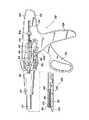
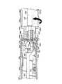
図1は、本発明の好ましい実施形態に基づいて構成された外科用ステープル止め装置の斜視図である。図において、各々がステープル止め装置において使用されるよう構成された3つの異なるサイズの使い捨てローディングユニットが設けられている。
図2は、図1に示す外科用ステープル止め装置のハンドルアセンブリの分解斜視図である。
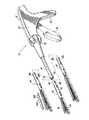
図3は、本発明の好ましい実施形態に基づいて構成された使い捨てローディングユニットの分解斜視図である。
図4は、図1に示す外科用ステープル止め装置におけるのハンドルアセンブリおよびボディの一部断面を含む斜視図である。この場合、図3に示す使い捨てローディングユニットが、ボディの先端に挿入される様子が図示されている。
図5は、図4と同様の一部断面を含む斜視図である。この場合、外科用ステープル止め装置のボディに取り付けられた使い捨てローディングユニット、および、使い捨てローディングユニットの挿入の結果として可能とされるハンドル部内での駆動機構が示されている。
【0027】
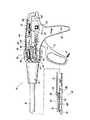
図6は、本発明の外科用ステープル止め装置の駆動前の側面図である。図においては、駆動前において、ハンドル部内に収容された駆動アセンブリの各部材の相対的位置関係を図示するために、ハンドル部が断面で示されている。
図7は、本発明の外科用ステープル止め装置において、駆動ハンドルが部分的に圧縮されたときの側面図である。図においては、使い捨てローディングユニットのアンビルを閉塞位置へと移動させるために、駆動ハンドルが部分的に圧縮されたときの、駆動アセンブリの各部材の相対的位置関係を図示するために、ハンドル部が断面で示されている。
図8は、本発明の外科用ステープル止め装置において、駆動ハンドルが解放されたときの側面図である。図においては、使い捨てローディングユニットのアンビルを開放位置へと移動させるために、駆動ハンドルが解放されたときの、駆動アセンブリの各部材の相対的位置関係を図示するために、ハンドル部が断面で示されている。
図9は、本発明の外科用ステープル止め装置において、アンビルが開放位置を維持する位置にまで駆動ハンドルを移動したときの側面図である。図においては、使い捨てローディングユニットのアンビルが開放位置を維持する位置にまで駆動ハンドルを移動したときの、駆動アセンブリの各部材の相対的位置関係を図示するために、ハンドル部が断面で示されている。
図10は、本発明の外科用ステープル止め装置において、駆動ハンドルを1回の完全な駆動ストローク分だけ操作したときの側面図である。図においては、使い捨てローディングユニットのステープルカートリッジからステープルの一部を生体組織に対して付与するために、駆動ハンドルを1回の完全な駆動ストローク分だけ操作したときの、駆動アセンブリの各部材の相対的位置関係を図示するために、ハンドル部が断面で示されている。
【0028】
図11は、本発明の外科用ステープル止め装置において、使い捨てローディングユニットをステープラーのボディの先端から取り外すときの側面図である。図においては、この場合の、駆動アセンブリの各部材の相対的位置関係を図示するために、ハンドル部が断面で示されている。
図12は、本発明における使い捨てローディングユニットの側面図である。図においては、管状ベッセルを固定するためのアンビルの閉塞前の、各部材の相対的位置関係を図示するために、使い捨てローディングユニットの本体が断面で示されている。
図13は、本発明における使い捨てローディングユニットの側面図である。図においては、装置が完全に発射した後の、各部材の相対的位置関係を図示するために、使い捨てローディングユニットの本体が断面で示されている。
図14は、図13と同様の使い捨てローディングユニットの側面図である。図においては、解放用スプリングの付勢のもとに、アンビルが開放位置へと移動する様子が示されている。
図15は、使い捨てローディングユニットの代替可能な実施形態を示す斜視図である。図においては、外科用クリップを付与するために適用される使い捨てローディングユニットが示されている。
【0029】
図16は、使い捨てローディングユニットの代替可能な実施形態を示す斜視図である。図においては、ただ1つの外科用ステープルを付与するために適用される使い捨てローディングユニットが示されている。
図17は、本発明の好ましい実施形態に基づいて構成された他の外科用ステープル止め装置の斜視図である。図において、装置には、使用可能な複数の異なるサイズの使い捨てローディングユニットのうちの1つが設けられている。
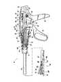
図18は、図17に示す外科用ステープル止め装置のハンドルアセンブリの分解斜視図である。ハンドルアセンブリを構成する各部材は、図示の容易化のために離間して示されている。
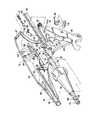
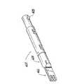
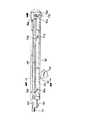
図19は、図17に示す外科用ステープル止め装置のボディの分解斜視図である。ボディ中を延在する長尺制御ロッドが示されている。
図20は、図19に示す制御ロッドの先端部を示す斜視図である。
【0030】
図21は、図17に示す外科用ステープル止め装置のボディ内に収容された内部支持チューブの基端部を示す断面図であって、図19における21−21線矢視断面に対応している。
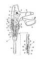
図22は、図17に示す外科用ステープル止め装置の一部断面を含む側面図である。図においては、使い捨てローディングユニットをボディの先端に取り付ける前のラックロックの向きを示している。
図23は、図17に示す外科用ステープル止め装置の一部断面を含む側面図である。図においては、使い捨てローディングユニットをボディの先端に取り付けた後のラックロックの向きを示している。
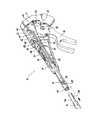
図24は、本発明の好ましい実施形態に基づいて構成された使い捨てローディングユニットの分解斜視図である。図において、使い捨てローディングユニットは、図19および図20に示す制御シャフトの長さ方向移動を制限するよう機能するロックアウトアセンブリを備えている。
図25は、図24に示すロックアウトアセンブリを、制御ロッドの先端とともに拡大して示す分解斜視図である。
【0031】
図26は、図24に示す使い捨てローディングユニットの基端部を示す一部断面を含む側面図である。図においては、使い捨てローディングユニットが、駆動準備状態とされたロックアウトアセンブリを備えるボディの先端に挿入されるときの様子が示されている。
図27は、図24に示す使い捨てローディングユニットの基端部を示す一部断面を含む側面図である。図においては、使い捨てローディングユニットの取付部が、ボディの先端に完全に挿入されたときの様子が示されている。
図28は、図24に示す使い捨てローディングユニットの基端部を示す一部断面を含む側面図である。図においては、使い捨てローディングユニットが、操作位置へと回転されるときの様子が示されている。
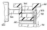
図29は、図26における29−29線矢視断面図である。図においては、制御ロッドのヘッドのノッチと、軸方向駆動アセンブリの基端における係合フィンガーとの軸合わせを示している。
図30は、図28における30−30線矢視断面図である。図においては、使い捨てローディングユニットが操作位置へと回転された後の、係合フィンガーに対する制御ロッドのヘッドの位置を示している。
【0032】
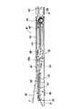
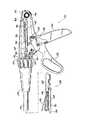
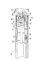
図31は、ステープル止め操作前における、図17に示す外科用ステープル止め装置を示す一部断面を含む側面図である。図において、アンビルは、開放位置にあり、駆動シャフトおよび歯状ラックは、ハンドルアセンブリ内において最も基端側の位置に配置されている。
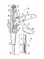
図32は、図17に示す外科用ステープル止め装置を示す一部断面を含む側面図である。図において、駆動シャフトおよび歯状ラックは、アンビルの図31に示す開放位置から閉塞位置への移動をもたらすために、クランプ用ストロークに伴って先端側に前進する。
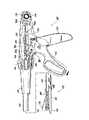
図33は、図17に示す外科用ステープル止め装置を示す一部断面を含む側面図である。図において、アンビルの図32に示す閉塞位置から開放位置への移動をもたらすために、引き抜き機構により、駆動シャフトおよび歯状ラックに対してラックロックおよび爪の係合が解除される様子が示されている。
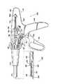
図34は、図32に対応する図であり、外科用ステープル止め装置を示す図である。図においては、駆動ハンドルがクランプ用ストローク分だけ操作された後であり、アンビルは、閉塞状態とされている。
図35は、図17に示す外科用ステープル止め装置を示す一部断面を含む側面図である。図においては、連続するステープル止めストローク時における、駆動シャフトの先端側への移動を可能とするための、ラックロックの手動解放を示している。
【0033】
図36は、図17に示す外科用ステープル止め装置を示す一部断面を含む側面図である。図においては、カートリッジからのステープルの部分的な連続する押出をもたらすための、駆動ハンドルの完全なステープル止めストロークに対応する駆動シャフトおよび歯状ラックの先端側への前進を示している。
図37は、図17に示す外科用ステープル止め装置を示す一部断面を含む側面図である。図においては、引き続いてのカートリッジからのステープルの押出を行うための、駆動ハンドルの2回目の完全なステープル止めストロークに対応する駆動シャフトおよび歯状ラックの先端側への前進を示している。
図38は、図17に示す外科用ステープル止め装置を示す一部断面を含む側面図である。図においては、駆動シャフトを引っ込めて、アンビルを図37に示す閉塞位置から開放位置へと移動させるために、引込ノブが基端側に引かれたときの、解放プレートによるラックロックと歯状ラックからの爪との係合解除を示している。
図39は、歯状ラックと、この歯状ラックに関連する解放プレートとを拡大して示す側面図である。図においては、歯状ラックに係合されたラックロックを示している。
図40は、歯状ラックと、この歯状ラックに関連する解放プレートとを拡大して示す側面図である。図においては、ラックロックを歯状ラックから係合解除するよう移動した解放プレートを示している。
【0034】
図41は、図39における41−41線矢視断面図である。
図42は、図40における42−42線矢視断面図である。
図43は、ラックロック(あるいは係合部材)を拡大して示す斜視図である。図においては、ラックロックの構造的幾何形状が示されている。
図44は、使い捨てローディングユニットを示す一部断面を含む側面図である。図においては、ステープル止め操作の完了時における、軸方向駆動アセンブリ、および、制御ロッドの位置を示している。
図45は、図24の使い捨てローディングユニットを示す一部断面を含む側面図である。図においては、発射後の基端位置に向けて引き抜かれている制御ロッドに対応する位置におけるロックアウトアセンブリの部材を示している。
【0035】
図46は、図24の使い捨てローディングユニットを示す一部断面を含む側面図である。図においては、制御ロッドが最も基端側の位置に近づいたときのロックアウトアセンブリの部材の向きを示している。
図47は、図24の使い捨てローディングユニットを示す一部断面を含む側面図である。図においては、制御ロッドが最も基端側の位置に引っ込められたときのロックアウトアセンブリの部材の向きを示している。
図48は、図24の使い捨てローディングユニットを示す一部断面を含む側面図である。図においては、バヨネット結合を解除するためにローディングユニットがボディに関して先端側に移動したときのロックアウトアセンブリの部材の向きを示している。
図49は、図24の使い捨てローディングユニットを示す一部断面を含む側面図である。図においては、ローディングユニットの連続使用を阻止するための阻止位置に図示されたロックアウトアセンブリの部材とともに、ステープル止め操作の完了時において、ボディの先端から係合が解除された使い捨てローディングユニットを示している。
図50は、図46における50−50線矢視断面図である。図においては、使い捨てローディングユニットがボディの先端から取り外される前の、阻止プレート、および、制御ロッドを示している。
図51は、使い捨てローディングユニットがボディの先端から取り外された後の、使い捨てローディングユニットを示す一部断面を含む拡大された斜視図である。図においては、制御ロッドの先端が、軸方向駆動アセンブリの駆動ブロック内に入らないような、阻止位置におけるロックアウトアセンブリを示している。
【0036】
以下の図面中、および、説明中においては、慣例にしたがって、”基端部”という用語は、ステープル止め装置のうち、操作者に最も近い側の端部を指すものとする。また、”先端部”という用語は、ステープル止め装置のうち、操作者に最も遠い側の端部を指すものとする。
【0037】
さて、図面においては、本発明の同様の部材には、同様の参照符号を付すものとする。そして、図1においては、本発明の好ましい実施形態に基づいて構成された外科用装置が、全体的に符号10で示されている。簡単に言えば、外科用装置10は、外科用ステープル止め装置である。外科用ステープル止め装置は、生体組織に係合し、生体組織に対して複数の外科用ファスナーを付与し、そして開腹的外科施述時には、結合された生体組織に切開口を形成するよう構成されている。装置10は、また、外科用クリップ、あるいは他のファスナー(以下において、より詳細に説明される)を付与するためにも使用することができる。しかしながら、この説明中においては、使い捨てローディングユニット内に配設されたステープルカートリッジから平行な複数のステープル列を付与する場合について、主に説明する。
【0038】
外科用装置10は、複数の異なるサイズの使い捨てローディングユニットを使用することができるという点において、公知の開腹用デバイスに対して、特有のものである。しかも、装置10は、長さが30mm、45mm、あるいは60mmである直線状のステープル列(図1)を付与する、あるいは、他のタイプのファスナー(図15および図16)を付与する個々の使い捨てローディングユニットとともに操作可能であるよう構成されていることが好ましい。よって、開腹的外科施述時においては、複数の作業をこなすために、複数の相互交換可能な使い捨てローディングユニットを使用するに際しても、ただ1つだけの器具で済ませることができる。詳細に説明される好ましい実施形態は、主に、直線的なステープル列を付与するために使用される使い捨てローディングユニットに関連している。
【0039】
図1に示すように、外科用装置10は、ハンドルアセンブリ12、および、長尺のボディ14を備えている。装置10は、使い捨てローディングユニット30、45、60とともに使用される。使い捨てローディングユニット30、45、60は、各々が、キャリア32、ステープルカートリッジ34、アンビル36を有している。アンビル36に対しては、ハウジングから押し出されたステープルが駆動されることになる。以下の説明により、装置およびこの装置に関して使用される使い捨てローディングユニットの、構成および操作が詳細に理解されるであろう。
【0040】
図2に示すように、ハンドルアセンブリ12は、長尺のバレル部22により画成されるハウジング20と、バレル部から垂下された固定ハンドル24と、バレル部に対して回転可能に取り付けられかつ固定ハンドルに対して移動可能とされた駆動ハンドル26とを備えている。駆動ハンドル26は、ハウジング20内において回転ピン28により支持されており、また、コイル状ねじりスプリング38により反時計方向の移動を妨げるよう付勢されている。
【0041】
駆動ハンドル26は、バレル部22内に取り付けられた駆動シャフト40の直線移動を制御する。さらに詳細には、駆動シャフト40は、上部に形成された歯状ラック42を有している。また、駆動ハンドル26は、ラチェット爪44を有している。ラチェット爪44は、駆動ハンドル26に取り付けられており、前進方向に係合して、駆動シャフト40を前進させるためのものである。爪44は、回転ピン46により取り付けられており、また、コイル状ねじりスプリング48は、爪44を、歯状ラック42に対して係合する向きに付勢している。直線状付勢用支柱50は、バレル部内に支持されており、爪を付勢するためのかつ駆動ハンドルを回転ピン28回りの時計方向回転を阻止するよう付勢するためのコイル状圧縮スプリング52により先端側に向けて付勢されている。付勢用支柱50は、また、爪44の傾斜付後方カム面に対して作用するよう機能する。この場合、支柱50に対してカム表面が接触することにより、爪44が時計方向に(ラック42から離れる向きに)回転することになる。器具が静止状態にあるときには、爪44は、歯状ラック42から離れるよう付勢されている。駆動ハンドル26が基端側に引かれたときには、爪44は、支柱50から移動し、反時計方向に回転する。そして、爪44は、駆動シャフト40の歯と係合する。この結果、駆動ハンドル26により、駆動シャフト40を先端側に移動させることが可能となる。
【0042】
駆動シャフト40は、常態においては、バレル部22内において、付勢力の一定なスプリング54により基端側に向けて付勢されている。スプリング54は、駆動シャフト40の先端近傍に、従来より公知の固定手段により、駆動シャフト40に取り付けられている。付勢力の一定なスプリング54は、ハンドルアセンブリ12のハウジング20内に設けられたボス56に支持されている。駆動シャフト40の先端部の下面には、キャビティ58が形成されている。このキャビティ58は、制御ロッド64のフランジ付基端部62に係合してこれを保持するためのものである。制御ロッド64は、外科用ステープラー10の長尺ボディ14内にわたって同軸に延在しており、使い捨てローディングユニットの基端部において、使い捨てローディングユニットと相互作用を行う。よって、駆動ハンドル26を操作することにより、駆動シャフト40を直線的に前進させれば、これに対応して、制御ロッド64が長さ方向に移動することになる。そして、これとともに、以下において詳細に説明するように、使い捨てローディングユニットが駆動されることになる。
【0043】
さらに、図2に示すように、外科用ステープラー10の長尺ボディ14の基端部は、この基端部上に形成された環状フランジ66を有している。この環状フランジ66は、バレル部22内においてバレル部22の先端近傍に形成された環状凹所68に係合する。この係合により、2つの構造部材は、固定的に取り付けられる。凹所68内へのフランジ66の係合により、バレル部22に対するボディ14の長さ方向軸回りの回転運動が案内される。カラー70は、ステープラーのボディ14の基端部に、一対の対向する突起72、74により、固定的に取り付けられている。よって、カラー70の回転は、ボディ14の回転に対応して引き起こされ、外科用ステープラー10の操作応用範囲を増大させる。
【0044】
ハンドルアセンブリ12内には、ラックロック80と駆動シャフト40の歯状ラック42との係合を開始させるための機構が設けられている。ラックロック80は、付勢力の一定なスプリング54の付勢のもとに、駆動シャフト40の長さ方向位置を維持する。ラックロック80は、使い捨てローディングユニットがボディ14の先端部に操作可能に係合されない限りはまた係合されるまでは、ラックと係合することはない。上記係合開始機構は、図2に示されており、それのラックロック80との相互作用は、また、図4、5を参照することによりよく理解される。係合開始機構は、長尺の梁または支柱82を有している。長尺の梁または支柱82には、先端タング84が設けられている。先端タング84は、ステープラーのボディ14内にスライド可能に取り付けられている支持チューブ88の基端部近傍に形成されたキーパーノッチ86に係合する。梁82は、コイル状付勢スプリング92の基端部を係合するための中央フック80を有している。コイル状付勢スプリング92の先端部は、バレル部22内に設けられたボス94に取り付けられている。付勢スプリング92は、梁82を、また支持チューブ88を、基端側へ移動することを阻止するよう付勢する。アーチ状カムフィンガー96は、ラックロック80の本体100の下部表面に画成された傾斜カム表面98と相互作用するために、梁82から基端側に突出している。ラックロック80は、さらに、楔状クラスプ部102を有している。楔状クラスプ部102は、器具10の操作時に、駆動シャフト40の長さ方向位置を維持するために、歯状ラック42の歯と係合する寸法とされ、また係合するよう構成されている。ラックロック80の本体100は、ハウジング20のバレル部22内に設けられたボス104に取り付けられている。また、ボス104には、コイル状ねじりスプリング106が取り付けられている。コイル状ねじりスプリング106は、本体100に対して、ラックロックが歯状ラック42に係合するよう付勢するよう接続されている。
【0045】
図4、5に示すように、使い捨てローディングユニット30のキャリア32の基端部が長尺ボディ14の先端部内に挿入されたときには、支持チューブ88は、スプリング92の付勢力に抗して、基端方向に駆動される。それに伴って、梁82は、基端側に移動し、アーチ状カムフィンガー96は、傾斜カム表面98に当接する。これにより、ラックロック80が持ち上げられ、ラックロックがねじりスプリング106の付勢力に抗して反時計方向に回転する。この時点において、梁82のカムフィンガー96は、ラックロック80の本体100内に形成された凹所108内に収容される。ラックロックがこの位置にあるときには、ラックロックは、駆動ハンドルの操作に伴って駆動シャフト40が先端側に前進する際に、駆動シャフト40と係合することになる。ラックロック80と駆動シャフト40との相互作用については、器具10が生体組織を拘束して生体組織にファスナーを付与する方法に関連して、以下において詳細に説明する。
【0046】
さて、図3には、使い捨てローディングユニットの一例が示されており、使い捨てローディングユニットには、全体として符号30が付されている。既に述べたように、使い捨てローディングユニット30は、長さが約30mmである直線状の複数のステープル列を付与するために特に構成されたものであって、外科施述時に器具10とともに使用し得る複数のサイズまたはタイプの使い捨てローディングユニットのうちの1種にすぎない。ステープル止めユニット30のキャリア32は、長尺のチャネル(先端収納部)110を備えている。チャネル110は、ベース112と、ステープルカートリッジ34およびアンビル36を支持するための複数の取付構造を有する2つの平行直立壁114、116とを備えている。キャリア32は、また、取付部(基端取付部)120を備えている。取付部120は、互いに離間して設けられた複数の矩形タング122がチャネル110の対向壁114、116に形成された複数の対応するスロット124に係合することにより、チャネル110の基端部に取り付けられている。取付部120の基端領域126は、長尺ボディ14の先端部内に挿入可能な寸法とされまた挿入可能に構成されている。また、制御ロッド64の先端を受け入れるための同軸孔125が設けられている。
【0047】
基端領域126からは、結合用ステム128が径方向外方に突出している。この結合用ステム128は、長尺ボディ14の先端部の壁に形成されたJ字形結合用スロット130(図4、5を参照)と相互作用するためのものである。ステム128およびスロット130は、共に従来のバヨネット型結合をもたらすものであり、外科施述時におけるステープル止めユニットのステープラーに対する、素早くかつ容易な係合および取外しを促進する。一旦、ステープラーの長尺体14の先端部に係合した後には、支持チューブ88の先端部は、コイル状スプリング92の付勢のもとに基端領域126を先端側に向けて付勢する。これにより、結合用ステム128は、結合用スロット130内での拘束が維持される。
【0048】
さらに、図3に示すように、チャネル110の先端部は、ステープルカートリッジ34を支持している。ステープルカートリッジ34は、複数の外科用ファスナー(ステープル)132、および、複数の対応する押出機またはプッシャー(ステープルプッシャー)134を含有している。押出機またはプッシャー134は、駆動スレッド140によりファスナー駆動力が与えられたときには、カートリッジ34からファスナーを駆動する。ステープルカートリッジ34は、側方支柱136がチャネル壁114、116の上部表面に対して摩擦係合することにより、また、タブ138のようなハウジングタブがノッチ139に対して凹凸嵌合することにより、チャネル110内に維持される。これらの構造は、チャネル11内におけるステープルカートリッジ34の横方向の、長さ方向の、および浮き上がり方向の移動を制限するように機能する。
【0049】
互いに離間した複数の長さ方向スロット142は、駆動スレッド140の直立カム楔144を収容し得るよう、ステープルカートリッジ34にわたって延在している。スロット142は、内部に複数のファスナー132およびプッシャー134がそれぞれ支持されている横断保持スロット146と連通している。操作時に、駆動スレッド140がステープルカートリッジ34内を移動したときには、カム楔144の傾斜した前端は、次々と、プッシャー134に当接する。これによって、プッシャーは、スロット146内を縦方向に移動し、スロット146からファスナー132を飛び出させる。駆動スレッド140とプッシャー134との間の相互作用の結果は、図12〜図14に示されている。これについては、図面を参照して以下において説明する。合わせて、Green氏と共有で出願した米国特許No.4,978,049を参照されたい。この文献中の開示は、その全体が参考のためにここに組み込まれる。
【0050】
さらに、図3に示すように、使い捨てローディングユニット30のアンビル36には、チャネル壁114、116の回転孔154、156に係合するような寸法とされまた係合するような構成とされた反対向きに突出する取付ウィング150、152が設けられている。スプリングアーム158a、158bを有する付勢部材158が、アンビル36の基端部に固定されている。スプリングアームは、アンビル36を常態において開放位置に向けて付勢するように、取付部120内に形成された内部抵抗表面に対して抵抗する。この場合、アンビル36の内部ファスナー形成表面155は、ステープルカートリッジ34から離間している。
【0051】
使い捨てローディングユニット30は、さらに、軸方向駆動アセンブリ160を備えている。軸方向駆動アセンブリ160は、ステープル止め操作時において、制御ロッド64により引き起こされる長さ方向駆動力を、駆動スレッド140に対して伝達するためのものである。駆動アセンブリ160は、先端作業ヘッド164および基端係合領域166を有する長尺の駆動梁162を備えている。係合領域166は、一対の係合フィンガー166a、166bを有している。一対の係合フィンガー166a、166bは、駆動ブロック168内に形成された対応する一対の保持スロット168a、168bに対して、取付可能に係合するような寸法とされまた係合するような構成とされている。駆動ブロック168は、基端丸孔170を有している。基端丸孔170は、使い捨てローディングユニット30の基端部がステープルのボディ14の先端内に挿入されたときには、制御ロッド64の先端を受け入れるためのものである。長尺ボディ14と結合用ステム128との結合において図示したのと同様に、バヨネット型の結合を形成するために、駆動ブロック168には、制御ロッド64の先端からステム(図示せず)を受け入れるための内部スロットを設けることができる。そのような結合は、制御ロッド64の移動に伴う操作者による駆動梁162の操作を可能とすることになる。駆動梁162の作業端部164は、ナイフ刃174を支持する直立支持支柱(支持フランジ)172と、駆動スレッド140の中央支持楔145に係合する当接表面176とから構成されている。ナイフ刃174は、ステープル操作時に生体組織のステープル列間に切開口を形成するために、駆動スレッド140のわずかに後方を移動する。直立支柱172からは、円柱状カムローラー180を保持するために、保持フランジ178が先端側に突出している。カムローラー180は、発射時に生体組織に対してアンビルを次第にクランプするために、アンビル36の外部カム表面182に対して、結合可能かつ移動可能な寸法とされまた結合可能かつ移動可能な構成とされている。
【0052】
長さ方向スロット184は、保持フランジ178および直立支柱172の移動を可能とするために、アンビル36にわたって延在している。バランスフランジ186は、フランジ186に形成された対応する保持ポート190内への保持脚188の係合を介して、駆動梁162の作業端部に固定されている。フランジ186は、アンビル36が次第にクランプされる際に、カムローラー180により発生するクランプ力をバランスさせるよう機能する。長さ方向スロット192が、発射時の保持脚188の長さ方向移動を可能とするために、チャネル110のベース112に形成されている。
【0053】
図1に示す使い捨てローディングユニット45においては、アンビル36の外部に沿って移動する部材から組織を保護するために、アンビルカバーが設けられている。特に、アンビルカバー400は、アンビルカバー400の下面に形成されたチャネル402を有しており、アンビル36との間にチャネルを形成するために、アンビル36の上面に固定されている。カムローラー180は、発射時には、カバー400とアンビル36との間のチャネル402内を移動する。アンビルカバー400は、プラスチックであることが好ましいが、適切な生体適合性を有する任意の材料から構成することができる。
【0054】
再度、図3を参照すると、付勢力の一定な2つのスプリング部材194、196がチャネルのベース112の基端部に接続されており、また、駆動ブロック168の先端側に配置されている。これにより、駆動ブロック168の先端側への移動を阻止するよう付勢している。図12〜図14に示すように、駆動ブロック168が先端側に移動したときには、スプリング部材194、196は、駆動ブロック168の移動端部が通り過ぎるまでは、巻き戻される。完全に巻き戻されると同時に、スプリング部材は、それらの通常の巻き位置へと復帰し、取付ブロックのためのバッファを形成する。したがって、発射後にブロックを最も基端側の位置に戻そうとしてもできないことになる。
【0055】
次に、図4〜図11を順に参照して説明する。器具10の操作を開始するために、まず、所望の使い捨てローディングユニットが選択される。このような使い捨てローディングユニットは、図1に示す異なるサイズの使い捨てローディングユニットのうちの1つ、あるいは、外科用クリップを付与するために使用される使い捨てローディングユニット(図15)のうちの1つ、あるいは、他のタイプの外科用ステープルを付与するために使用される使い捨てローディングユニット(図16)のうちの1つとすることができる。ここでは、直線状のステープル列を付与するために適用される使い捨てローディングユニットを使用した場合の器具の使用について説明する。使い捨てローディングユニット30は、図4に示すように、長尺ボディ14の先端内に、使い捨てローディングユニット30の基端取付領域を挿入することにより、ステープラーに対して取り付けられる。挿入に先立って、支持チューブ88は、長尺ボディ14内において最も先端側の位置にある。そして、スプリング92により、その位置に維持される。したがって、梁82のカムフィンガー96は、ラックロック80を、駆動シャフト40の歯状ラック42から離間した上方係合解除位置に維持する。
【0056】
一旦、使い捨てローディングユニットの基端が長尺ボディの先端部内に挿入されると、結合用ステム128を結合用スロットのベース内に位置させるよう、約10゜〜15゜回転させる。この場合、スプリング92の付勢力により支持チューブ88が先端側に移動し、ステム128がスロット130のベース内にロックされる。制御ロッド64と駆動ブロック168との間に結合システム(前述)が設けられている場合には、この回転により、これら部材が同様に結合されることになる。加えて、図5に示すように、取付部120の基端領域126が長尺ボディ14内に挿入されることにより支持チューブ88が基端側に移動したときには、梁82のアーチ状カムフィンガー96は、凹所108に到達するまで、カム表面98に沿って基端側に移動する。この場合、ラックロック80は、ねじりスプリング106の付勢のもとに、係合位置へと移動する。以上により、器具10は、使用準備状態となる。
【0057】
使用前においては、図6に示すように、駆動ハンドル26は、図示のような中立位置とされている。この位置においては、爪44は、駆動シャフト40の歯状ラック42からは離間した位置にある。加えて、駆動ハンドル26から先端側に突出しているリフトアーム210は、楔状クラスプ部102の近傍においてラックロック80の基端部に形成された張出フィンガー212の下部に係合している。リフトアーム210は、クラスプ部102を、ある操作条件のもとに、駆動シャフト40に対して係合しないようにする機能を有している。これについては、図8、9を参照して、以下において説明する。
【0058】
駆動ハンドル26を操作するに先立って、駆動シャフト40は、制御ロッド64と同様に、付勢力が一定のスプリング54により先端側への移動が阻止されるような向きに付勢されていることにより、最も基端側の位置にある。したがって、アンビル36は、スプリングアーム158a、158bにより閉塞を阻止する向きに付勢されていることにより、開放位置にある。よって、この場合、管状ベッセル200のような生体組織は、アンビル36の表面に形成されたファスナーとステープルカートリッジ34の組織接触表面との間に捕捉されることができる。
【0059】
図7に示すように、矢印”A”で示す方向に駆動ハンドル26が操作されると、爪44は、先端方向に移動して、反時計方向に回転し、歯状ラック42と係合する。そして、駆動シャフト40は、スプリング54の付勢力に抗して先端側に駆動される。結果的に、制御ロッド64が先端側に駆動され、使い捨てローディングユニット30内において駆動ブロック168を前方側に押し込む。したがって、駆動梁162の作業端部164は、先端側に移動する。そして、カムローラー180が、アンビル36のカム表面の基端部に係合し、アンビルは、ステープルカートリッジ34の組織接触表面に対して管状ベッセル200をクランプしながら、閉塞位置へと移動することになる。加えて、駆動シャフト40が先端側へ前進したときには、ラックロック80のクラスプ部102は、ねじりスプリング106による付勢のもとに、駆動シャフト40の先端近傍において歯状ラック42の先端に形成されたノッチ領域214に係合する。この場合、バレル部22内における駆動シャフト40の長さ方向位置は、維持され、アンビル36は、閉塞状態にロックされる。
【0060】
状況によっては、アンビルを開放して捕捉したベッセルまたは生体組織を開放すること、すなわち、ベッセルの異なる箇所を捕捉し直すことが要求されることがある。アンビルを開放するには、図8に示すように、矢印”B”で示す方向に向けて、直線状圧縮スプリング52の付勢力に抗して、駆動ハンドル26が操作される。結果的に、アーム210は、フィンガー212を持ち上げ、図9に示すように、ラックロック80をねじりスプリング106の付勢力に抗して反時計方向に回転させる。ラックロック80のクラスプ部102は、これにより、ノッチ領域214からの係合が解除され、駆動シャフト40および制御ロッド64の最も基端側位置への復帰が許容される。この時点において、駆動ブロック168は、スプリング部材194、196の付勢力により基端側に移動する。したがって、カムローラー180は、アンビル36の外部カム表面182から引っ込められ、そして、アンビルは、スプリング部材158の付勢のもとに開放位置へと移動する。引き続くアンビルの閉塞は、図7に関して上述した方法により得ることができる。
【0061】
器具10により発射を行って、アンビル36とステープルカートリッジ34との間にクランプされた組織に複数の外科用ファスナー132を付与するには、図10に示すように、矢印”C”で示す方向に固定ハンドル24に向けて、ねじりスプリング38の付勢力に抗して、駆動ハンドル26が操作される。この場合、爪44は、歯状ラック42と係合し、駆動シャフト40を付勢力が一定のスプリング54の付勢力に抗して先端側に駆動する。直線状のステープル列を有する使い捨てローディングユニットにより発射を行うという好ましい実施形態においては、駆動ハンドル26の1回の完全なストロークにより、駆動シャフト40のバレル部22内における約15mmの前進が引き起こされる。これとともに、制御シャフト64が駆動梁162に対して長さ方向の駆動力を伝達することにより、使い捨てローディングユニット30内においては、駆動梁162が、同じ距離だけ移動する。結果として、30mmのステープルカートリッジ34内における外科用ファスナー132の半分が、駆動ハンドル26の1回の完全なストロークにより、ステープルカートリッジ34から押し出される。駆動シャフト40は、ラックロック80のクラスプ部102と歯状ラック42との係合により、この長さ方向に前進した位置に維持される。引き続く解放、および、駆動ハンドル26の緩和位置への移動は、したがって、駆動シャフト40の長さ方向位置に影響を与えることはない。
【0062】
ステープルの発射操作を完了させるために、駆動ハンドル26は、再度、固定ハンドル24に向けて接近させられる。これにより、爪44は、歯状ラック42に係合し、駆動シャフト40をさらに15mmだけ先端方向に前進させる。よって、駆動シャフト26の2回の完全なストロークが行われたことになり、駆動シャフトは、バレル部22内において、30mm前進することになる。このとき、駆動梁162の作業端部164は、ステープルカートリッジ34内を通って、ステープルカートリッジ34からすべての外科用ファスナーを連続的に発射する。要望によっては、操作者は、複数回の短いストロークにより制御シャフト64を徐々に先端方向に前進させることができる。この場合、最小前進距離は、ラック42の歯間の直線間隔により決定される。したがって、15mmの好ましいストローク距離からなる2回の完全なストロークを(30mmの使い捨てローディングユニットにおいて発射を行うために)使用することができるけれども、完全なストロークは、必要ではなく、あるいは、要求されない。
【0063】
図12〜図14に示すように、駆動ハンドル26の2回の完全なストロークは、駆動シャフト40および関連する制御ロッド64を、駆動ブロック168がチャネル110の基端近傍に位置している図12に示すような最も基端側位置から、駆動ブロック168がステープルカートリッジ34の先端に向けて移動している図13に示すような最も先端側位置へと移動させる。移動の途中においては、駆動ブロック168は、駆動梁166を先端側へ移動させ、管状ベッセル200に対してのアンビル36の漸次的な閉塞をもたらす。そして、駆動スレッド140がステープルカートリッジ34内を挿通移動することにより、生体組織に対して外科用ファスナー132が次々と押し出される。図13に示すように、カムローラー180が行程の先端まで到達したときには、カムローラー180は、アンビルスロット184の先端に形成された横断スロット185内に落ち込む。結果として、アンビル36は、スプリング部材158による付勢のもとに、図14に示すようにステープル止めされた生体組織を解放して、開放位置へと復帰する。さらに、スプリング部材194、196は、巻き戻されて、チャネル110の基端部においてコイル状態に復帰する。
【0064】
上記のような発射操作が完了すると、使い捨てローディングユニット30は、図11に示すように、長尺ボディ14の先端から取り外される。同時に、支持チューブ88は、スプリング92の付勢力のもとに最も先端側位置へと復帰することが許容される。したがって、梁82は、先端側へ移動し、これに伴って、アーチ状カムフィンガー96は、ラックロック80を持ち上げて、駆動シャフト40の歯状ラック42との係合を解除させる。結果として、駆動シャフト40は、バレル部22内において、付勢力が一定のスプリング54の付勢のもとに、最も基端側位置へと復帰する。この場合、新たな使い捨てローディングユニットを器具の連結して、さらなる外科手法を施すことができる。
【0065】
各々の長さが約45mmの平行なステープル列を付与することを外科医が所望する場合には、使い捨てローディングユニット45(図1)が、長尺ボディ14の先端に取り付けられる。取付後に、駆動シャフト40および制御ロッド64を45mmだけ先端方向に前進させるために、3回の完全な駆動ストロークに等しいストローク分だけ、駆動ハンドル26が複数回にわたって操作される。これに代えて、長さが約60mmのステープル列を付与するために使い捨てローディングユニット60が選択された場合には、駆動シャフト40および制御ロッド64を60mmだけ先端方向に前進させるために、4回の完全な駆動ストロークに等しいストローク分だけ、駆動ハンドル26が複数回にわたって操作されなければならない。
【0066】
図15および図16には、使い捨てローディングユニットの2つの代替可能な実施形態が示されている。図15に示す使い捨てローディングユニット410は、外科用クリップを付与するために構成されている。使い捨てローディングユニット410は、あご構造412、および、ハウジング414内に収容された複数のクリップを有している。共有で出願した米国特許No.5,100,420における開示は、その全体が参考のためにここに組み込まれる。この文献中においては、クリップをあご構造412に供給する方法、および、クリップを付与する方法が開示されている。図16に示す使い捨てローディングユニット420は、例えば、ヘルニアの治療に有効なような個々の外科用ステープルを付与するために構成されている。使い捨てローディングユニット420は、あご構造422、および、ハウジング424内に収容された複数のステープルを有している。共有で出願した米国特許No.5,289,963における開示は、その全体が参考のためにここに組み込まれる。この文献中においては、ステープルをあご構造422に供給する方法、および、ステープルを付与する方法が開示されている。使い捨てローディングユニット410、420は、上述の使い捨てローディングユニットと同様の方法で外科用器具に固定され、そして、駆動シャフト40および制御ロッド64の長さ方向移動により駆動される。
【0067】
駆動シャフトにより移動されるストローク距離が所望の外科施述に応じて調整可能であるべきことは、望ましいことであり、当業者の要求するところである。例えば、長さが40mm、60mm、あるいは80mmの平行なステープル列を付与するような使い捨てローディングユニットが要望されることもある。この場合は、駆動シャフトにより移動される前進方向のストローク距離は、約20mm単位で調整することができる。加えて、当業者は、制御ロッド64の前進を制御するための代替可能な構造、あるいは、代替可能な構造の向きを要望するかもしれない。歯状ラック42は、回転させた向きで配置しても良い。その場合、歯面はハンドルの側を向いて下向きに設けられることとなり、ロックおよび爪は、下側からラックに係合するよう移動する。また、例えば、使い捨てローディングユニットの実際の発射前に取り外さなければならないハンドルのロックアウトのような様々な安全機構を付加することもできる。これらの特徴点、および、他の特徴点について、以下において詳細に説明する。
【0068】
図17には、本発明の好ましい実施形態に基づいて構成された他の外科用ステープル止め装置が、全体的に符号500で示されている。上記実施形態と同様に、外科用ステープル止め装置500は、生体組織に係合し、生体組織に対して複数の外科用ファスナーを付与し、そして開腹的外科施述時には、結合された生体組織に切開口を形成するよう構成されている。装置は、長さが30mm、45mm、あるいは60mmである直線状のステープル列を付与する個々の使い捨てローディングユニット(図1)、あるいは、他のタイプの使い捨てローディングユニット(図15および図16)とともに操作可能であるよう構成されていることが好ましい。
【0069】
図17に示すように、外科用ステープラー500は、ハンドルアセンブリ512、および、長尺のボディ514を備えている。ステープラー500は、使い捨てローディングユニット530、あるいは図示しない他の使い捨てローディングユニットとともに使用される。使い捨てローディングユニット530は、キャリア532、ステープルカートリッジ534、アンビル536を有している。アンビル536に対しては、カートリッジから押し出されたステープルが駆動されることになる。
【0070】
図18に示すように、上記実施形態と同様に、ハンドルアセンブリ512は、バレル部522により画成されるハウジング520と、固定ハンドル524と、回転駆動ハンドル526とを備えている。駆動ハンドル526は、ハウジング520内において回転ピン528により支持されており、また、ねじりスプリング538により固定ハンドル524から遠ざかるように付勢されている。駆動ハンドル526は、ハウジング520のバレル部522内に支持された駆動シャフト540の直線移動を制御する。さらに詳細には、駆動シャフト540は、駆動シャフト540の下面に形成された歯状ラック542を有している。また、駆動ハンドル526は、爪544を有している。爪544は、歯状ラック542に選択的に係合するよう取り付けられており、駆動ハンドル526の駆動ストローク分の操作に対応して駆動シャフト540を先端方向に前進させるためのものである。爪544は、回転ピン546により駆動ハンドル526に対して取り付けられており、また、コイル状ねじりスプリング548により歯状ラック542に向けて付勢されている。爪544の取付部は、ハンドルアセンブリ512のハウジング520内に形成された当接表面545と相互作用するよう湾曲している。さらに詳細には、爪544の湾曲した取付部が当接表面545に当接したときには、爪は、駆動シャフト540の歯状ラック542との係合を解除するよう回転される。
【0071】
駆動シャフト540は、常態においては、バレル部522内において、付勢力の一定なスプリング554により基端側に向けて付勢されている。スプリング554は、ハウジング520内に設けられたボス556に支持されている。駆動シャフト540の基端近傍において、駆動シャフト540の上面には、ノッチ領域555が形成されている。このノッチ領域555は、付勢力の一定なスプリング554の自由端に設けられた係合タブ557を収容しかつ保持するためのものである。駆動シャフト540の先端には、制御ロッド564のフランジ付基端部564pと係合するための捕獲部材558が設けられている。制御ロッド564は、ハンドルアセンブリ512から長尺ボディ514を通って延在しており、ボディの先端に支持された使い捨てローディングユニット530と相互作用を行う。よって、駆動ハンドル526を操作することにより、駆動シャフト540および制御ロッド564の上記操作に対応した長さ方向の移動を引き起こす。これにより、以下において詳細に説明するような方法で、使い捨てローディングユニットが駆動されることになる。
【0072】
さらに、図18に示すように、外科用ステープラー500の長尺ボディ514の基端部は、この基端部上に形成された環状フランジ566を有している。この環状フランジ566は、バレル部522内においてバレル部522の先端近傍に形成された環状凹所568内に収容される。この係合により、ハンドルアセンブリ512に対するボディ514の長さ方向軸回りのボディ514の回転運動が補助される。カラー570は、ボディ514に対して、少なくとも1つの572により、固定的に取り付けられている。よって、カラー570の回転は、ボディ514の軸回りの回転に対応して引き起こされ、外科用ステープラー500の操作応用範囲を増大させる。
【0073】
上記実施形態と同様に、外科用ステープラー500は、ラックロック(または、係合部材)580を備えている。ラックロック580は、駆動シャフト540の歯状ラック542と相互作用するものであり、バレル部522内での駆動シャフト540の長さ方向位置を付勢力が一定のスプリング554の付勢力に抗して選択的に維持させるものである。ラックロック580は、使い捨てローディングユニットがボディ514の先端部内に挿入されたときにのみ、歯状ラック542と相互作用する位置に移動するような方法で取り付けられている。さらに詳細には、ラックロック580は、回転ピン583に取り付けられておりかつコイル状ねじりスプリング585により歯状ラック542に向けて付勢されているものであって、使い捨てローディングユニットがデバイス内に導入されるまでは、当接支柱582により相互作用しない位置に維持される。当接支柱582は、固定フランジ586に取り付けられる。固定フランジ586は、図21に示すように、ボディ514内において軸方向移動可能に設けられている支持チューブ588の基端部に形成されている。コイル状付勢スプリング592は、ハンドルアセンブリ512のハウジング520内において、当接支柱582をボス593と結合する。付勢スプリング592は、実効的には、支持チューブ88を先端側に付勢する。この結果、使い捨てローディングユニットの挿入時において、支持チューブ588および当接支柱582は、基端方向に移動する。
【0074】
さらに詳細には、図22に示すように、ローディングユニット530の挿入に先立って、当接支柱582から基端側に突出しているアーチ状カムフィンガー596が、ラックロック580に形成された傾斜カム表面598の基端部と相互作用する位置とされる。同時に、ラックロック580は、コイル状ねじりスプリング585の付勢に抗して、相互作用しない位置に維持される。その後、図23に示すように、ローディングユニット530がボディ514の先端内に挿入されて、そして、関連する部材(ステム628a、628b、および、スロット630a、630b)間においてバヨネット結合を形成するよう回転されたときには、支持チューブ588および当接支柱582は、コイルスプリング592(およびコイルスプリング597)の付勢力に抗して、基端側へ移動する。結果として、基端カムフィンガー596がカム表面598に沿って基端方向に移動し、ラックロック580を、ねじりスプリング585の付勢のもとに、ピン583回りに相互作用位置へと回転させる。この場合、駆動シャフト540の歯状ラック542は、駆動シャフト540の先端側への移動により係合することができる。
【0075】
図22、23に示すように、当接支柱582の反対側には、第2の当接支柱584が配設されている。第2の当接支柱584は、当接支柱582と同じ方法で支持チューブ588の基端部に結合されている。当接支柱584と、当接支柱584に係合するとともにボス591によりハウジング520に結合されているスプリング597とは、付加的な付勢力をもたらし、使い捨てローディングユニット530とボディ514との間のバヨネット結合を確実に維持する。
【0076】
図19に示すように、長尺スロット602が、支持チューブ588の部分に沿って延在して設けられており、また、横方向溝604が、制御ロッド564の中央部から径方向外方に延在する支持ピン608を収容し得るように、ボディ514の軸方向孔606に沿って延在して設けられている。この構成は、ボディ514および制御ロッド564に関する支持チューブ588の長さ方向移動を可能とする。しかしながら、3つの同軸構造体の相対的な角度配向は維持されたままであり、カラー570によるこれら3部材の軸方向回転を容易なものとしている。
【0077】
さて、図24には、図3に示す使い捨てローディングユニットと実質的に同様の方法で構成された使い捨てローディングユニット530が示されている。使い捨てローディングユニット530は、ステープルカートリッジ534およびアンビル536を支持するための長尺の支持チャネル(先端収納部)610を有するキャリア532と、ボディ514の先端に着脱可能に係合されるよう構成された取付部(基端取付部)620とを備えている。さらに詳細には、取付部620の基端部626には、一対の結合用ステム628a、628bが設けられている。一対の結合用ステム628a、628bは、ボディ514の先端部に形成されたJ字形結合用スロット630a、630b(図26を参照)と相互作用するためのものである。結合用ステムおよびJ字形スロットは、共に従来のバヨネット型結合をもたらすものであり、ステープラーに対するローディングユニットの係合および取外しを容易とする。上記実施形態と同様に、軸方向孔625は、取付部620の基端部626を挿通して延在しており、制御ロッド564の先端部564dを受け入れる。
【0078】
上記実施形態と同様に、使い捨てローディングユニット530は、軸方向駆動アセンブリ660を備えている。軸方向駆動アセンブリ660は、各部材間において、制御ロッド564により引き起こされる長さ方向駆動力を、ステープルカートリッジ534を挿通して延在しかつ互いに離間した長さ方向スロット642内に配設される駆動スレッド640に対して伝達するためのものである。複数のステープルプッシャー643が、スロット642に関連して操作可能に設けられており、駆動アセンブリ660により駆動スレッド140がステープルカートリッジ534内を挿通駆動されたときには、駆動スレッド640により、次々と接触される。ステープルプッシャーは、ステープルカートリッジ534から次々とステープルが押し出されるように、ステープルカートリッジ534内に収容された複数のステープルと相互作用する。
【0079】
駆動アセンブリ660は、図25に示すように、先端作業ヘッド664を有する2股に分かれた駆動梁662と、駆動ブロック668と組立的に係合するよう構成された一対の係合フィンガー666a、666bを有する基端係合領域665とを備えている。駆動ブロック668は、基端丸孔670を有している。基端丸孔670は、例えば、図27に示すように、使い捨てローディングユニット530の基端取付領域626が長尺ボディ514の先端内に挿入されたときには、制御ロッド564の先端564dを受け入れるためのものである。
【0080】
図20に示すように、制御ロッド564の先端部564dには、フランジ667が形成されている。フランジ667には、図26および図29に示すように、制御ロッドが駆動ブロック668の基端側入口670内に収容されるときに、2つの反対側に位置する係合フィンガー666a、666bを収容し得るような寸法とされた一対の径方向反対側に位置するノッチ669a、669bが形成されている。その後、図28および図30に示すように、ローディングユニット530が結合用ステム628a、628bをJ字形結合用スロット630a、630b内に係合させるよう軸回りに約20゜回転したときには、係合フィンガー666a、666bは、係合ノッチ669a、669bからは位置がずれるように移動し、フランジ667は、使い捨てローディングユニット530に固定される。この固定は、使い捨てローディングユニット530が外科用ステープラー500から取り外されるまで続く。図27と図28とを比較すればわかるように、駆動ブロック668の内部キャビティ671は、ローディングユニット530のボディ514の先端内への挿入時に、制御ロッド564の先端564dの入口670内への侵入を許容し得るような寸法とされている。
【0081】
再度、図24を参照すると、駆動アセンブリ660の作業ヘッド664は、部分的には、ナイフ刃674を支持している直立支持支柱(支持フランジ)672により形成されており、駆動スレッド640に係合するための当接表面675を有している。直立支柱672からは、カムローラー680を保持するために、保持フランジ678が先端側に突出している。カムローラー680は、アンビル536の外部カム表面682に沿って移動し得るよう構成されており、ステープル止め操作時においては、アンビルスプリング676の付勢に抗してのアンビルの閉塞をもたらすものである。長さ方向スロット684は、保持フランジ678の移動を可能とするために、アンビル536にわたって延在している。同様のスロット692が、バランスフランジ686を支持している保持脚688の移動を許容するために、チャネル610のベース612に形成されている。フランジ686は、カムローラー680によりもたらされるアンビル536に対するクランプ力をバランスさせるよう機能する。上記実施形態と同様に、ステープル止め操作時にアンビル536の外部表面682上を移動する部材による接触から生体組織を保護するために、アンビルカバー(図示せず)を設けることができる。
【0082】
図24および図25に示すように、使い捨てローディングユニット530には、識別される2つの段階において動作するよう構成されたロックアウトアセンブリ700が設けられている。要約すれば、動作の第1段階においては、ロックアウトアセンブリは、軸方向駆動アセンブリ660に対する制御ロッド564の長さ方向移動を制限するよう機能する(図46を参照されたい)。動作の第2段階においては、ステープル止め操作後に装置から使い捨てローディングユニットが取り外された後において、ロックアウトアセンブリは、駆動ブロック668の基端側入口670内への制御ロッド564の侵入を妨害することにより、使い捨てローディングユニットの連続使用を阻止するよう機能する(図51を参照されたい)。
【0083】
図25に示すように、好ましいロックアウトアセンブリ700は、阻止プレート710を備えている。阻止プレート710は、阻止プレート710から基端側に延在する一対の平行な支持アーム712a、712bを有している。阻止プレート710には、制御ロッド564の長さ方向移動を許容し得るような寸法とされかつ許容し得るよう構成された中央孔716が形成されている。孔716には、駆動梁662の基端部665の係合フィンガー666a、666bを収容するために、径方向反対側にスロット717a、717bが形成されている。保持スプリング718が、一対の互いに離間したタブ720a、720bが対応する一対のポート722a、722bに係合することにより、阻止プレート710に接続されている。保持スプリング718は、取付フランジ724を有しており、この取付フランジ724により、使い捨てローディングユニット530の取付部620の内部表面における取付領域725に対して固定される(図26を参照されたい)。保持スプリング718の基端部には、一対の互いに離間したカム傾斜部726a、726bが設けられている。カム傾斜部726a、726bは、使い捨てローディングユニット530が装置から取り外されたときに制御ロッド564の先端フランジ667と相互作用し得るよう、基端側に向けて傾斜している(全体的には、図47を参照されたい)。
【0084】
ロックアウトアセンブリ700は、さらに、支持プレート730を備えている。支持プレート730は、保持スプリング718の付勢に抗して阻止プレートを非阻止位置に維持するために阻止プレート710の支持アーム712a、712bと相互作用する一対の突出アーム732a、732bを有している(図26))。支持プレート730には、駆動梁662の下部を案内するための中央スロット領域733が形成されている。スロット領域733内には、駆動梁662の下部に形成された先端側および基端側の係合凹所735a、735bと相互作用するための拘束凸部734が形成されている。
【0085】
使用時において、例えば図44に示すように、駆動梁662が先端側に駆動されたときには、拘束凸部734と基端側凹所735bとの係合により、駆動梁662に連れて移動する。結果として、阻止プレート710は、解放され、保持スプリング718の付勢のもとに、制御ロッド564の長さ方向軸を横切る方向に移動する。例えば図45に示すように、制御ロッド564が孔716を挿通して延在している場合には、阻止プレート710は、非阻止位置のままである。しかしながら、ステープル止め操作後に、制御ロッド564がアンビル536を開放するために完全に引き抜かれたときには、阻止プレート710は、阻止位置に移動し、図46に示すように、制御シャフト564の先端部564dと係合する。この位置においては、阻止プレート710は、制御ロッド564の長さ方向移動範囲を有効的に制限する。範囲は、制御ロッド564の先端における縮径部により決められる。
【0086】
駆動ブロック668からフランジ667が完全に引き抜かれたときには、阻止プレート710は、保持スプリング718の付勢のもとに、図49に示すように、駆動ブロック668の基端側入口670を閉鎖するための完全阻止位置へと自由に移動することができる。ロックアウトアセンブリ700の機能、および、ロックアウトアセンブリ700の制御ロッド564および軸方向駆動アセンブリ660との相互作用について、以下において、さらに詳細に説明する。
【0087】
次に、図31〜図38を順に参照して説明する。外科用ステープラー500の操作を開始するために、まず、一群の異なるユニットの中から所望のサイズおよび種類の使い捨てローディングユニットが選択され、そして、ボディ514の先端内に装着される。ローディングユニット、すなわち、ローディングユニット530が、基端取付部626をボディ514の先端内に挿入して、バヨネット結合を確実に形成するようユニットを回転させることにより、ステープラー500に対して取り付けられる(図22、23を参照されたい)。回転角度は、約5゜〜約40゜が好ましく、約20゜が最も好ましい。挿入とともに、支持チューブ588が、図22に示す位置から、図23に示す位置へと基端側に移動される。結果として、ラックロック580は、図31に示す相互作用位置へと移動する。この場合、駆動シャフト540の歯状ラック542は、駆動シャフト540の先端側への移動に伴って係合されることになる。図31に示すように、駆動シャフト540が付勢力の一定なスプリング554により付勢されて最も基端側の位置にあるときには、アンビル536は、管状ベッセル750のような生体組織を受け入れるための開放位置にある。この場合、爪544は、歯状ラック542の最も先端側に位置する歯に係合しており、また、駆動ハンドル526は、歯状ラックを前進させるために、スプリング538の付勢力に抗して操作することができる。
【0088】
図32に示すように、駆動ハンドル526を駆動ストロークの初期分だけ(すなわち、クランプ用ストローク分だけ)初期操作すると、駆動シャフト540は、爪544と歯状ラック542との相互作用により先端方向に駆動される。この場合、ラックロック580の係合フック752は、駆動シャフト540の先端固定部558近傍に形成されたキーパーノッチ754に係合する。同時に、アンビル536は、アンビル表面682の基端カム部に沿ったカムローラー680の前進により、閉塞位置へと移動する。そして、係合フック752の基端部は、駆動シャフト540の下部表面に形成された支持部755に当接する。結果として、駆動シャフト540のこれ以上の先端側への移動は禁止され、また、アンビル536はクランプした位置に維持される。
【0089】
仮に、この時点で、装置の使用者がアンビル536を開放することにより管状ベッセル750を解放することを所望した場合であっても、それは、ハンドルアセンブリ512に設けられた引込機構(後述)により達成することができる。引込機構は、図33に示すような使用者の基端側への駆動シャフトの引き移動を許容するために、駆動シャフト540からラックロック580および爪544の係合を解除するよう機能する。
【0090】
図18に戻って説明すると、引込機構は、一対の引込ノブ760a、760bを備えていることが好ましい。一対の引込ノブ760a、760bは、結合ロッド762を介して駆動シャフト540の基端部に接続されている。結合ロッド762は、引込ノブ760a、760bを受けるための左右の係合部764a、764bと、駆動シャフト540の基端部近傍に形成された一対の長さ方向スロット766a、766b内において移動可能な寸法とされかつ移動可能に形成された中央部764cとを有している。解放プレート768が、駆動シャフト540に関連して操作可能に設けられている。解放プレート768は、引込ノブ760a、760bの操作に対応して、駆動シャフト540に関して移動可能に取り付けられている。さらに詳細には、一対の離間したピン(カムピン)767a、767bが、解放プレート768に形成された対応する一対の傾斜カムスロット769a、769bに係合するよう、駆動シャフト540の側面から外方に突出して設けられている。カムスロットは、駆動シャフト540に対しての、厳密には歯状ラック542に対しての解放プレートの移動経路を画成する。解放プレート768の基端部には、結合ロッド762の中央部764cを収容するために、縦方向スロット770が形成されている。そして、引込ノブ760a、760bが駆動シャフト540に対して相対移動されたときの結合ロッド760の長さ方向移動を許容するために、ハンドルアセンブリ512のバレル部522内には、長尺スロット772、774が形成されている。結合ロッド762は、スプリング765aにより先端側に付勢されている。スプリング765aは、一端が結合ロッドの一部765cに固定されており、他端が駆動シャフト540のポスト765bに固定されている。
【0091】
再度、図33を参照すると、クランプされた生体組織750を解放するためにアンビル536を開放したい場合には、装置500の使用者は、引込ノブ760a、760bを基端側に引けば良い。この場合、解放プレート768は、傾斜カムスロット769a、769bの経路に沿って全体的に基端側に移動する(図39、40を参照されたい)。これにより、解放プレートは、ラックロック580の係合フック752をキーパーノッチ754から外し、爪544を歯状ラック542から係合解除させる。したがって、使用者は、駆動シャフト540を基端方向に引くことができる。駆動シャフト540が基端方向に引かれると、カムローラー680は、駆動梁662と共に、基端方向に引かれることになる。結果として、アンビル536は、アンビルスプリング676の付勢のもとに、開放位置へと移動する。そして、駆動ハンドル526は、ねじりスプリング538の付勢のもとに、中立位置へと復帰する。一旦、駆動シャフト540が最も基端側の位置に戻ってしまうと、ステープル止め装置は、リセット状態となる。
【0092】
さて、再度、生体組織750をクランプするためには、駆動ハンドル526は、駆動ストロークのクランプ分だけ操作される。すると、ラックロック580の係合フック752が再度キーパーノッチ754と係合しかつ支持部755に当接する状態にまで、駆動シャフト540が先端側に駆動される。この時点において、装置500の使用者が、ステープル止め操作の開始を確信したならば、駆動シャフト540のさらなる先端側への移動を可能とするために、ラックロック580をキーパーノッチ754から手動で外さなければならない。これは、ハンドルアセンブリ512に操作可能に設けられた手動解除機構により達成される。手動解除機構は、図35に示すように、ラックロック580の基端側解除端757と相互作用を行う。ラックロック(または、係合部材)580の好ましい構成の詳細は、図43に示されている。
【0093】
再度、図18に戻って説明すると、手動解除機構は、好ましくは、回転解除部材780を備えている。回転解除部材780は、ボス784に取り付けられているとともに、コイル状ねじりスプリング786によりラックロック580の基端側解除端757から遠ざかるように付勢されている。解除部材780から側方に向けて反対側に突出する一対の小翼、すなわち小翼788が設けられている。一対の小翼788は、それぞれ、解除ノブ790a、790bを支持するためのものである。解除部材780は、下向きノーズ(解除フィンガー)792を備えており、この下向きノーズ792は、使用者により解除ノブ790a、790bが図35における矢印”A”方向に操作されたときにラックロック580の基端側解除端757に当接し得る寸法とされている。
【0094】
再度、図35を参照すると、解除ノブ790a、790bが操作され、これに伴ってラックロック580が解放されたときには、駆動シャフト540は、駆動ハンドル526の操作に応じて先端方向に移動自在とされる。この場合、駆動シャフト540の直線位置は、爪544と歯状ラック542との係合により維持される。
【0095】
図36に示すように、ステープル止め用のストローク分だけの固定ハンドル524に向けての駆動ハンドル526の操作は、爪544による歯状ラック542の前進を引き起こす。これによって、駆動シャフト540および制御ロッド564は、先端方向に前進する。結果として、使い捨てローディングユニット530内に支持された軸方向駆動アセンブリ660は、先端側に駆動される。これにより、軸方向駆動アセンブリ660は、駆動スレッド640をプッシャー643に交差させ、カートリッジ534から次々とステープルを押し打させる。同時に、ナイフ刃674は、駆動スレッド640の後方を進み、ステープル止めされた生体組織に切開口を形成する。図36に示すように、1回の完全なステープル止めストロークは、カートリッジ534内のステープルの一部の発射しかもたらさない。上述のように、駆動ロッド564を前進方向に前進させるために、すなわち、爪544がラック542を1回につき1歯ずつ前進させるように、複数回の部分的なストロークを、また、使用することもできる。
【0096】
図37に示すように、カートリッジ534内のすべてのステープルは発射され、管状ベッセル750に対して付与される。ステープル止め装置500に対して図示のものよりも長いローディングユニットが使用されている場合には、さらに駆動シャフト540を前進させるために、付加的なステープル止め用のストロークが要求されることになる。全体として、駆動シャフト540の歯状ラック542は、少なくとも4回の各々が15mmであるような完全なステープル止め用ストロークを許容し得る寸法とされていることが好ましい。よって、駆動ハンドル526の完全なステープル止め用ストロークの各々が駆動シャフトを15mm前進させる場合には、ステープル止め装置500は、完全なストロークの全回を使用して15mm、30mm、45mm、60mmのステープル列を付与するよう構成された使い捨てローディングユニットを使用して発射することができる。
【0097】
図38に示すように、ステープル止め操作の完了時において、アンビル536を開放位置へと移動して外科用装置500からステープル止めされた生体組織750を解放するためには、使用者は、ハンドルアセンブリ520のバレル部522に設けられた引込ノブ760a、760bを使用する。さらに詳細には、図39〜図42に示すように、ノブ760a、760bが基端側に引かれると、結合ロッド762(図18)が、駆動シャフト540の基端部に形成された長さ方向スロット766a、766b内において基端側に移動する。結果として、解放プレート768は、カムスロット769a、769bにより画成される傾斜通路に沿って移動する。これにより、ラックロック580の係合フック752および爪544(図示せず)の歯状ラック542との係合が解除される。この場合、図38に示すように、駆動シャフト540は、使用者および付勢力の一定なスプリング554による付勢のもとに、基端方向への移動が自由とされる。これに伴って、使い捨てローディングユニット530内の軸方向駆動アセンブリ660は、制御ロッド564のヘッドにより基端側に引かれ、アンビル536は、カムローラー680が引かれることにより開放位置へと移動する。
【0098】
図45に示すように、図44に示す最も先端側の位置から基端側に向けて制御ロッド564が引かれると、阻止プレート710は、制御ロッド564に沿って移動し、保持スプリング718の付勢力に抗して上位置に維持される。しかしながら、図46に示すように、制御ロッド564の縮径先端部564dが最も基端側位置に近づくと、阻止プレート710は、孔716の周縁部が制御ロッド564の先端部564dに係合するよう、制御ロッドに向けて駆動される(図50も合わせて参照されたい)。制御ロッド564がさらに基端側に移動すると、駆動ブロック668は、図47に示すような最も基端側の位置へと引かれる。この場合、フランジ667は、保持スプリング718のカム傾斜部762a、762bと相互作用し、少なくとも部分的に阻止プレート710を持ち上げる。これとともに、制御ロッド564の先端移動は、阻止プレート710とロッド564の径が拡径されている基端部564d側の拡径棚部との間の相互作用により制限される。しかしながら、制御ロッド564は、なお、制御ロッド564の縮径部564dに沿って、制限された範囲における長さ方向移動の余裕を有している。その結果、アンビル536は、開放位置・閉塞位置間で移動することができる。したがって、アンビル536は、トロカー(trocar)および套管デバイスを介した外科用装置500の取り外しを容易とするために容易に閉塞することができる。
【0099】
図47に示すように、軸方向駆動アセンブリ660、および、軸方向駆動アセンブリ660とともに設けられた駆動ブロックが最も基端側位置にあるときには、支持プレート730上の拘束凸部734は、先端凹所735aと係合する。これとともに、支持プレート730は、使い捨てローディングユニット530が外科用装置500から取り外された後に、使い捨てローディングユニット530内における阻止プレート710の浮き上がりを防止するために、最終停止位置に確実に保持される。
【0100】
使い捨てローディングユニット530をボディ514の先端から取り外すには、図48に示すように、ローディングユニットを、基端側に移動させ、バヨネット結合を外すように回転させる。同時に、係合フィンガー666a、666bは、フランジ667内のノッチ669a、669bと再び位置合わせされる。この場合、フランジは、阻止プレート710をさらに上方に付勢して、使い捨てローディングユニット530のボディ514の先端からの取り外しを可能とする。フランジ667がカム傾斜部762a、762bおよび阻止プレート710を超えて移動するとすぐに、阻止プレートは、保持スプリング718による付勢のもとに、完全阻止位置への移動が自由とされる。図51に示すような位置においては、駆動ブロック668の基端側入口670内への制御ロッド564の先端の侵入が、禁止されていることが好ましい。したがって、発射済みのあるいは部分的に発射済みの使い捨てローディングユニットは、外科用装置500からの取り外し後においては、引き続いて使用することはできない。
【0101】
本発明が好ましい実施形態について説明されてきたけれども、本発明は、特許請求の範囲において限定した本発明の精神または範囲を逸脱することなく、変更または修正が可能であることは、当業者にとっては明らかである。
【0102】
なお、本出願は、1995年8月28日出願の継続中の特許出願No.08/520,202の一部継続出願である。
【図面の簡単な説明】
【図1】 本発明の好ましい実施形態に基づいて構成された外科用ステープル止め装置の斜視図である。
【図2】 図1に示す外科用ステープル止め装置のハンドルアセンブリの分解斜視図である。
【図3】 本発明の好ましい実施形態に基づいて構成された使い捨てローディングユニットの分解斜視図である。
【図4】 図1に示す外科用ステープル止め装置におけるのハンドルアセンブリおよびボディの一部断面を含む斜視図である。
【図5】 図4と同様の一部断面を含む斜視図である。
【図6】 本発明の外科用ステープル止め装置の駆動前の側面図である。
【図7】 本発明の外科用ステープル止め装置において、駆動ハンドルが部分的に圧縮されたときの側面図である。
【図8】 本発明の外科用ステープル止め装置において、駆動ハンドルが解放されたときの側面図である。
【図9】 本発明の外科用ステープル止め装置において、アンビルが開放位置を維持する位置にまで駆動ハンドルを移動したときの側面図である。
【図10】 本発明の外科用ステープル止め装置において、駆動ハンドルを1回の完全な駆動ストローク分だけ操作したときの側面図である。
【図11】 本発明の外科用ステープル止め装置において、使い捨てローディングユニットをステープラーのボディの先端から取り外すときの側面図である。
【図12】 本発明における使い捨てローディングユニットの側面図である。
【図13】 本発明における使い捨てローディングユニットの側面図である。
【図14】 図13と同様の使い捨てローディングユニットの側面図である。
【図15】 使い捨てローディングユニットの代替可能な実施形態を示す斜視図である。
【図16】 使い捨てローディングユニットの代替可能な実施形態を示す斜視図である。
【図17】 本発明の好ましい実施形態に基づいて構成された他の外科用ステープル止め装置の斜視図である。
【図18】 図17に示す外科用ステープル止め装置のハンドルアセンブリの分解斜視図である。
【図19】 図17に示す外科用ステープル止め装置のボディの分解斜視図である。
【図20】 図19に示す制御ロッドの先端部を示す斜視図である。
【図21】 図17に示す外科用ステープル止め装置のボディ内に収容された内部支持チューブの基端部を示す断面図であって、図19における21−21線矢視断面に対応している。
【図22】 図17に示す外科用ステープル止め装置の一部断面を含む側面図である。
【図23】 図17に示す外科用ステープル止め装置の一部断面を含む側面図である。
【図24】 本発明の好ましい実施形態に基づいて構成された使い捨てローディングユニットの分解斜視図である。
【図25】 図24に示すロックアウトアセンブリを、制御ロッドの先端とともに拡大して示す分解斜視図である。
【図26】 図24に示す使い捨てローディングユニットの基端部を示す一部断面を含む側面図である。
【図27】 図24に示す使い捨てローディングユニットの基端部を示す一部断面を含む側面図である。
【図28】 図24に示す使い捨てローディングユニットの基端部を示す一部断面を含む側面図である。
【図29】 図26における29−29線矢視断面図である。
【図30】 図28における30−30線矢視断面図である。
【図31】 ステープル止め操作前における、図17に示す外科用ステープル止め装置を示す一部断面を含む側面図である。
【図32】 図17に示す外科用ステープル止め装置を示す一部断面を含む側面図である。
【図33】 図17に示す外科用ステープル止め装置を示す一部断面を含む側面図である。
【図34】 図32に対応する図であり、外科用ステープル止め装置を示す図である。
【図35】 図17に示す外科用ステープル止め装置を示す一部断面を含む側面図である。
【図36】 図17に示す外科用ステープル止め装置を示す一部断面を含む側面図である。
【図37】 図17に示す外科用ステープル止め装置を示す一部断面を含む側面図である。
【図38】 図17に示す外科用ステープル止め装置を示す一部断面を含む側面図である。
【図39】 歯状ラックと、この歯状ラックに関連する解放プレートとを拡大して示す側面図である。
【図40】 歯状ラックと、この歯状ラックに関連する解放プレートとを拡大して示す側面図である。
【図41】 図39における41−41線矢視断面図である。
【図42】 図40における42−42線矢視断面図である。
【図43】 ラックロック(あるいは係合部材)を拡大して示す斜視図である。
【図44】 使い捨てローディングユニットを示す一部断面を含む側面図である。
【図45】 図24の使い捨てローディングユニットを示す一部断面を含む側面図である。
【図46】 図24の使い捨てローディングユニットを示す一部断面を含む側面図である。
【図47】 図24の使い捨てローディングユニットを示す一部断面を含む側面図である。
【図48】 図24の使い捨てローディングユニットを示す一部断面を含む側面図である。
【図49】 図24の使い捨てローディングユニットを示す一部断面を含む側面図である。
【図50】 図46における50−50線矢視断面図である。
【図51】 使い捨てローディングユニットがボディの先端から取り外された後の、使い捨てローディングユニットを示す一部断面を含む拡大された斜視図である。
【符号の説明】
10 外科用ステープラー
12 ハンドルアセンブリ
14 ボディ
22 バレル部
26 駆動ハンドル
30 使い捨てローディングユニット
32 キャリア
34 ステープルカートリッジ
36 アンビル
40 駆動シャフト(歯状駆動ラック)
44 爪部材
45 使い捨てローディングユニット
60 使い捨てローディングユニット
64 制御ロッド
110 チャネル(先端収納部)
120 取付部(基端取付部)
132 外科用ファスナー(ステープル)
134 ステープルプッシャー
140 駆動スレッド
162 駆動梁
172 直立支持支柱(支持フランジ)
174 ナイフ刃
180 カムローラー
182 外部カム表面
410 使い捨てローディングユニット
420 使い捨てローディングユニット
500 外科用ステープラー
512 ハンドルアセンブリ
514 ボディ
522 バレル部
526 駆動ハンドル
530 使い捨てローディングユニット
532 キャリア
534 ステープルカートリッジ
536 アンビル
540 駆動シャフト(歯状駆動ラック)
544 爪部材
554 付勢力の一定なスプリング
564 制御ロッド
610 チャネル(先端収納部)
620 取付部(基端取付部)
634 ステープルプッシャー
640 駆動スレッド
662 駆動梁
672 直立支持支柱(支持フランジ)
674 ナイフ刃
680 カムローラー
682 外部カム表面
700 ロックアウトアセンブリ
710 阻止プレート
730 支持プレート
754 キーパーノッチ
752 係合フック
760a 引込ノブ
760b 引込ノブ
767a ピン(カムピン)
767b ピン(カムピン)
768 解放プレート
769a 傾斜カムスロット
769b 傾斜カムスロット
780 回転解除部材
790a 解除ノブ
790b 解除ノブ
792 下向きノーズ(解除フィンガー)[0001]
BACKGROUND OF THE INVENTION
The present invention relates to a surgical stapling apparatus, and more particularly to a device for continuously applying a plurality of surgical fasteners to a living tissue, and additionally, an incision for a fixed tissue. It is about.
[0002]
[Prior art]
Surgical devices that first grasp or fix tissue between opposing jaw structures and then join with surgical fasteners are well known in the art. In some instruments, a knife is provided, which cuts tissue already joined by a fastener. The fastener is typically in the form of a surgical fastener. However, two part polymeric fasteners are also available.
[0003]
The instrument for this purpose comprises two elongate members, each used to capture or fix tissue. Typically, one of the elongate members includes a staple cartridge that houses a plurality of staples provided in at least two lateral rows. On the other hand, the other of the elongate members has an anvil that defines a surface for forming staple legs when the staples are driven from the staple cartridge. Generally, the stapling operation is effected by a cam bar that moves longitudinally through the staple cartridge. In this case, the cam bar operates on the staple pusher to continuously push the staples out of the staple cartridge. The knife can be moved between the staple rows to cut and / or open the stapled tissue between the staple rows. Such an instrument is described, for example, in US Pat. 3,079,606 and U.S. Pat. 3,490,675.
[0004]
U.S. Pat. More recent staplers disclosed in US Pat. No. 3,499,591 apply two rows of staples on each side of the incision. This is achieved by providing a disposable introduction unit. In this case, in the introduction unit, the cam member moves in a long guide path located between two sets of grooves provided with staggered staples. The staple drive member is disposed in the groove and is positioned such that a longitudinally moving cam is in contact so that staples can be fired from the staple cartridge of the disposable introduction unit. Other examples of such staplers are described in US Pat. 4,429,695 and U.S. Pat. No. 5,065,929.
[0005]
Each instrument described above was configured to be used in a conventional surgical procedure where the surgeon had direct manual access to the operating area. However, in an endoscopic or open procedure, the surgical procedure is performed through a small incision or through a narrow cannula inserted through a small entrance opened into the skin. Endoscopic surgical stapling devices have been developed to meet the specific needs of endoscopic and / or open surgical procedures. These are disclosed, for example, in US Pat. 5,040,715 (Green et al.), US Pat. 5,307,976 (Olson et al.), US Pat. 5,312,023 (Green et al.), US Pat. 5,318,221 (Green et al.), US Pat. 5,326,013 (Green et al.), US Pat. 5,332,142 (Robinson et al.).
[0006]
U.S., the applicant of the present invention. S. Surgical has been working for several years for Multifire Endo GIA.* 30, Multifire ENDO GIA* Endoscopic stapling instruments such as 60 have been manufactured and sold. These instruments have yielded significant clinical results. Nevertheless, improvements are possible. For example, reducing costs and making manufacturing easier.
[0007]
[Problems to be solved by the invention]
Current open linear stapling devices are configured to be operated using a single size disposable loading unit (US Surgical) and a staple cartridge (Ethicon). For example, individual linear staplers can be utilized to provide parallel staple rows that are currently 30 mm, 45 mm, and 60 mm in length. Thus, during normal operation, the surgeon needs to use a plurality of different stapling instruments, even when performing only one open surgical procedure. Such an approach increases the time, complexity and overall cost associated with open surgical procedures. In addition, designing and manufacturing various sizes of staplers can be very costly compared to creating a single multipurpose stapler.
[0008]
Surgical devices that allow the use of multiple different size disposable loading units so that they can be used during open and / or endoscopic surgical procedures to reduce the overall cost associated with such procedures. It is very useful to provide. Also particularly effective are devices of different sizes and capable of performing various tasks using disposable loading units of different purposes, such as stapling, clipping and / or cutting.
[0009]
In improving or modifying current instruments, the Multifire Endo GIA as compared to other commercial products, such as endoscopic stapling instruments manufactured and sold by Ethicon.* It is highly desirable not to compromise any significant advantages of 30 and 60. Improvements, for example, effectively provide a fresh knife blade for each firing of the instrument, and are disposable in the stapling instrument until it is moved again unless the operator attempts to move it. It was ensured that the loading unit was securely maintained. These advantages are described in U.S. Pat. S. This is what has been done so far in Surgical instruments, and not in Ethicon instruments.
[0010]
Thus, for a reliable surgical stapler and the disposable loading unit used with this stapler, it retains all the advantages of the instrument currently marketed by the applicant, in addition to cost and manufacturing. There is a need to reduce the complexity of.
[0011]
[Means for Solving the Problems]
The present invention is primarily for applying multiple rows of surgical fasteners to living tissue, and preferably accompanied by an incision between rows of staples during an endoscopic or open surgical procedure. It has been made with respect to a stapling device that forms a mouth. A particularly unique feature of the stapling device described herein is that many different disposable loading units can be used. Furthermore, the stapling device of the present invention can be used with a disposable loading unit configured to provide a linear staple row having a length of about 15 mm to about 60 mm.
[0012]
In a preferred embodiment of the surgical stapler of the present invention, the device comprises a long barrel portion, a handle assembly comprising a drive handle movable by a drive stroke, and extending distally from the barrel portion of the handle assembly. And a long body defining a longitudinal axis. An elongate drive shaft is provided to be supported on at least a portion of the barrel portion of the handle assembly, and the drive shaft has a specific linear dimension. The drive handle interacts with the drive shaft such that operation of the drive handle with a complete drive stroke causes the drive shaft to move a predetermined linear distance.
[0013]
The disposable loading unit is operably engaged with the distal end of the elongated body. The disposable loading unit preferably comprises a carrier, a staple cartridge containing a plurality of staples, drive means (movable through the housing and staple cartridge), and an anvil. The drive shaft of the instrument drives the drive means across the staple cartridge to push the staples against the anvil to form a staple line having a specific linear length. The linear length of the staple line preferably corresponds to the distance that the drive shaft travels in response to operation of the drive handle over a complete or partial drive stroke over a specified number of times greater than one.
[0014]
The drive shaft is preferably defined at least in part by a toothed rack having a specific rack length. The drive handle has a pawl member that selectively engages with the toothed rack and advances the drive shaft in accordance with the operation of the drive handle. When a disposable loading unit having a linear row of staples is used, the linear dimension of the staple line imparted by the stapling unit is preferably proportional to the longitudinal travel distance of the drive shaft. In the most preferred embodiment, the minimum linear dimension of the staple line is always greater than the maximum linear distance that the drive shaft moves in response to a complete drive stroke.
[0015]
When a disposable loading unit having an anvil is used, the drive handle is preferably movable over a clamping stroke in which the drive shaft moves a predetermined clamping distance for moving the anvil from the open position to the closed position. The clamping stroke is made at the beginning of any number of complete or partial drive strokes. In the preferred embodiment, an engagement hook is provided in the barrel portion of the handle assembly to selectively maintain the drive shaft in a particular position after movement of the clamp distance. And in order to receive an engagement hook and hold | maintain so that attachment or detachment is possible, the notch is formed in the front-end | tip part of a drive shaft in the front-end | tip of a tooth-shaped rack.
[0016]
In a preferred embodiment use embodiment, the engagement hook releases the drive shaft when the drive handle moves in the opposite direction to the clamping stroke. As a result, the anvil can be moved to the open position. Lifting fingers are provided on the flange extending from the drive handle. The lifting finger moves the engagement hook to release the engagement with the notch of the engagement hook when the drive handle moves in the direction opposite to the clamping stroke. Preferably, a first biasing spring is provided in the handle assembly for biasing the drive handle in a clockwise direction. A second biasing spring is also provided in the handle assembly for biasing the drive handle counterclockwise about the handle rotation center. The counterclockwise direction corresponds to the direction of the clamping and driving strokes.
[0017]
The engagement hook is preferably configured to interact with the toothed rack to maintain the drive shaft in a particular length position during the drive stroke. In a normal state, the engagement hook is biased in a direction to engage with the drive shaft. Operable relative to the proximal end of the stapler body to maintain the engagement hook in a position that does not engage the drive shaft until the disposable loading unit is operably engaged to the distal end of the elongated body Abutment struts or beams are provided on the. The abutment strut allows the engagement hook to engage the drive shaft after the disposable loading unit is operably engaged to the distal end of the elongated instrument body.
[0018]
In another preferred embodiment of the surgical stapler disclosed herein, the handle assembly allows for subsequent advancement of the drive shaft in response to operation of the drive handle over any number of subsequent stapling strokes. In order to achieve this, a release mechanism for releasing the engagement of the engagement hook from the drive shaft is operably provided. In addition, the handle assembly has a retraction mechanism for providing manual retraction of the drive shaft at any point in the drive stroke so that the drive means can be retracted to allow movement of the anvil from the closed position to the open position. It is provided so that it can be operated.
[0019]
In a preferred embodiment of the device described herein, the disposable loading unit is used to apply a plurality of linear staple rows and is detachable from the distal end of an elongated instrument body. A carrier having a proximal end operatively coupled thereto; a long staple cartridge supported within the carrier and including a plurality of surgical fasteners and a plurality of fastener pushers for extruding the fasteners; and a fastener pusher And an anvil supported by the carrier and movable between an open position and a closed position with respect to the staple cartridge. The anvil preferably has a fastener forming surface that is driven when the fastener is pushed out of the staple cartridge by the fastener pusher. The anvil preferably has a cam surface on the opposite side of the fastener-forming surface. Preferably, the drive means is wedge-shaped drive means that moves within the staple cartridge to successively interact with the fastener pusher to push the fastener out of the staple cartridge.
[0020]
It is preferable that the disposable loading unit further includes a long driving beam including a proximal end engaging portion, a distal end working portion having an abutting surface, and a cam member. The proximal engagement portion is configured to engage the distal end of the drive assembly when the abutment surface engages the drive means to push the staples from the staple cartridge upon firing. The cam member abuts against the cam surface of the anvil when fired. In use, the stapler drive assembly moves the drive beam across the carrier, resulting in an anvil occlusion or maintenance of the anvil occlusion by the cam member. At the same time, the stapler drive assembly moves the drive means through the staple cartridge. This provides a gradual interaction with the plurality of fasteners for firing the staples.
[0021]
Preferably, the cam member is in the form of a cylindrical cam roller attached to a flange extending from the tip working portion of the drive beam. A longitudinal slot is formed in the anvil to enable linear movement of the working portion of the drive beam. The working unit is provided with a vertical support flange on the side opposite to the cam roller for engaging the lower surface of the carrier when the cam roller is engaged with the cam surface of the anvil. Longitudinal slots are also formed on the underside of the carrier to allow linear movement of the working part of the drive beam. An additional anvil cover can be provided to prevent living tissue from inadvertently touching the drive beam or cam roller during launch.
[0022]
Preferably, a knife blade is operably supported in the vicinity of the distal end of the working portion of the drive beam to form an incision in the stapled biological tissue. Preferably, the drive means is a sled with a planar base and upright cam wedges spaced apart from one another, each having an angled tip for interacting with a fastener pusher within the staple cartridge.
[0023]
In the preferred embodiment of the stapling device described herein, the distal end of the elongate body and the proximal end of the carrier have portions for forming a bayonet type bond. The bayonet type coupling facilitates convenient removal and engagement of a variety of different sizes of disposable loading units including disposable loading units configured to provide staple rows that are approximately 30 mm, 45 mm, and 60 mm in length. To do. Accordingly, the device is expected to be marketed as a kit comprising at least one surgical instrument configured to drive a compatible disposable loading unit and a plurality of disposable loading units that vary in size and type. Is done. The disposable loading unit can be used to apply linear staple rows, clips, or other forms of fasteners. A common feature of these disposable loading units is that they use the longitudinal movement of the drive control rod of the instrument to apply the fastener.
[0024]
These and other features of the present invention will become more apparent to those skilled in the art from the following detailed description of preferred embodiments of the device with reference to the drawings.
[0025]
DETAILED DESCRIPTION OF THE INVENTION
Various embodiments of the surgical stapling apparatus of the present invention will be described below with reference to the accompanying drawings.
[0026]
FIG. 1 is a perspective view of a surgical stapling apparatus constructed in accordance with a preferred embodiment of the present invention. In the figure, three different sized disposable loading units are provided, each configured to be used in a stapling apparatus.
FIG. 2 is an exploded perspective view of the handle assembly of the surgical stapling apparatus shown in FIG.
FIG. 3 is an exploded perspective view of a disposable loading unit constructed according to a preferred embodiment of the present invention.
FIG. 4 is a perspective view including a partial cross section of the handle assembly and body in the surgical stapling apparatus shown in FIG. In this case, a state in which the disposable loading unit shown in FIG. 3 is inserted into the tip of the body is illustrated.
FIG. 5 is a perspective view including a partial cross section similar to FIG. In this case, a disposable loading unit attached to the body of the surgical stapling apparatus and a drive mechanism within the handle portion that is enabled as a result of insertion of the disposable loading unit are shown.
[0027]
FIG. 6 is a side view of the surgical stapling apparatus of the present invention before driving. In the figure, the handle portion is shown in cross-section to illustrate the relative positional relationship of the members of the drive assembly housed within the handle portion prior to driving.
FIG. 7 is a side view of the surgical stapling apparatus of the present invention when the drive handle is partially compressed. In the figure, the handle portion is shown to illustrate the relative position of each member of the drive assembly when the drive handle is partially compressed to move the anvil of the disposable loading unit to the closed position. Shown in cross section.
FIG. 8 is a side view of the surgical stapling apparatus of the present invention when the drive handle is released. In the figure, the handle portion is shown in cross-section to illustrate the relative position of each member of the drive assembly when the drive handle is released to move the anvil of the disposable loading unit to the open position. Has been.
FIG. 9 is a side view of the surgical stapling apparatus of the present invention when the drive handle is moved to a position where the anvil maintains the open position. In the figure, the handle portion is shown in cross section to illustrate the relative positional relationship of each member of the drive assembly when the drive handle is moved to a position where the anvil of the disposable loading unit maintains the open position. Yes.
FIG. 10 is a side view of the surgical stapling apparatus of the present invention when the drive handle is operated for one complete drive stroke. In the figure, the relative position of each member of the drive assembly when the drive handle is operated by one full drive stroke to apply a portion of the staples from the staple cartridge of the disposable loading unit to the living tissue. In order to illustrate the target positional relationship, the handle portion is shown in cross section.
[0028]
FIG. 11 is a side view when the disposable loading unit is removed from the front end of the stapler body in the surgical stapling apparatus of the present invention. In the drawing, in order to illustrate the relative positional relationship of each member of the drive assembly in this case, the handle portion is shown in cross section.
FIG. 12 is a side view of the disposable loading unit according to the present invention. In the figure, the body of the disposable loading unit is shown in cross section to illustrate the relative positional relationship of each member prior to closure of the anvil for securing the tubular vessel.
FIG. 13 is a side view of the disposable loading unit according to the present invention. In the figure, the body of the disposable loading unit is shown in cross section to illustrate the relative position of each member after the device has been fully fired.
FIG. 14 is a side view of a disposable loading unit similar to FIG. In the figure, the anvil moves to the open position under the bias of the release spring.
FIG. 15 is a perspective view showing an alternative embodiment of a disposable loading unit. In the figure, a disposable loading unit applied for applying a surgical clip is shown.
[0029]
FIG. 16 is a perspective view showing an alternative embodiment of a disposable loading unit. In the figure, a disposable loading unit is shown which is applied to apply only one surgical staple.
FIG. 17 is a perspective view of another surgical stapling apparatus constructed in accordance with a preferred embodiment of the present invention. In the figure, the apparatus is provided with one of a plurality of different sized disposable loading units that can be used.
18 is an exploded perspective view of the handle assembly of the surgical stapling apparatus shown in FIG. Each member constituting the handle assembly is shown spaced apart for ease of illustration.
FIG. 19 is an exploded perspective view of the body of the surgical stapling apparatus shown in FIG. An elongate control rod extending through the body is shown.
FIG. 20 is a perspective view showing the tip of the control rod shown in FIG.
[0030]
21 is a cross-sectional view showing a proximal end portion of the internal support tube housed in the body of the surgical stapling apparatus shown in FIG. 17 and corresponds to a cross section taken along line 21-21 in FIG. .
FIG. 22 is a side view including a partial cross-section of the surgical stapling apparatus shown in FIG. In the figure, the direction of the rack lock before the disposable loading unit is attached to the tip of the body is shown.
23 is a side view including a partial cross-section of the surgical stapling apparatus shown in FIG. In the figure, the direction of the rack lock after the disposable loading unit is attached to the tip of the body is shown.
FIG. 24 is an exploded perspective view of a disposable loading unit configured according to a preferred embodiment of the present invention. In the figure, the disposable loading unit includes a lockout assembly that functions to limit the longitudinal movement of the control shaft shown in FIGS.
25 is an exploded perspective view showing the lockout assembly shown in FIG. 24 in an enlarged manner together with the tip of the control rod.
[0031]
FIG. 26 is a side view including a partial cross section showing a proximal end portion of the disposable loading unit shown in FIG. In the figure, the disposable loading unit is shown inserted into the tip of the body with a lockout assembly ready for driving.
FIG. 27 is a side view including a partial cross section showing a proximal end portion of the disposable loading unit shown in FIG. The figure shows a state where the mounting portion of the disposable loading unit is completely inserted into the tip of the body.
FIG. 28 is a side view including a partial cross section showing a proximal end portion of the disposable loading unit shown in FIG. In the figure, a state when the disposable loading unit is rotated to the operation position is shown.
29 is a cross-sectional view taken along line 29-29 in FIG. The figure shows the axial alignment of the control rod head notch and the engagement fingers at the proximal end of the axial drive assembly.
30 is a cross-sectional view taken along line 30-30 in FIG. The figure shows the position of the head of the control rod relative to the engagement fingers after the disposable loading unit has been rotated to the operating position.
[0032]
FIG. 31 is a side view including a partial cross section showing the surgical stapling apparatus shown in FIG. 17 before a stapling operation. In the figure, the anvil is in the open position and the drive shaft and toothed rack are located in the most proximal position within the handle assembly.
FIG. 32 is a side view including a partial cross section showing the surgical stapling apparatus shown in FIG. In the figure, the drive shaft and the toothed rack advance forward with the clamping stroke to effect movement of the anvil from the open position shown in FIG. 31 to the closed position.
33 is a side view including a partial cross section showing the surgical stapling apparatus shown in FIG. In the figure, the pulling mechanism is shown disengaging the rack lock and pawl from the drive shaft and toothed rack to effect movement of the anvil from the closed position shown in FIG. 32 to the open position. ing.
FIG. 34 corresponds to FIG. 32 and shows a surgical stapling apparatus. In the figure, the drive handle has been operated for the clamping stroke, and the anvil is closed.
35 is a side view including a partial cross section showing the surgical stapling apparatus shown in FIG. In the figure, manual release of the rack lock is shown to allow the drive shaft to move toward the tip side during successive stapling strokes.
[0033]
36 is a side view including a partial cross section showing the surgical stapling apparatus shown in FIG. In the figure, the drive shaft and tooth rack advancement corresponding to the full stapling stroke of the drive handle to provide partial continuous extrusion of the staples from the cartridge is shown.
FIG. 37 is a side view including a partial cross-section showing the surgical stapling apparatus shown in FIG. The figure shows the advancement of the drive shaft toward the distal end of the toothed rack corresponding to the second full stapling stroke of the drive handle for subsequent extrusion of the staples from the cartridge.
FIG. 38 is a side view including a partial cross section showing the surgical stapling apparatus shown in FIG. In the figure, the rack lock and toothed rack by the release plate when the retracting knob is pulled proximally to retract the drive shaft and move the anvil from the closed position shown in FIG. 37 to the open position. The disengagement with the nail | claw from is shown.
FIG. 39 is an enlarged side view showing a tooth-shaped rack and a release plate related to the tooth-shaped rack. In the figure, a rack lock engaged with a toothed rack is shown.
FIG. 40 is an enlarged side view showing the tooth-shaped rack and the release plate related to the tooth-shaped rack. In the figure, the release plate is shown moved to disengage the rack lock from the toothed rack.
[0034]
41 is a cross-sectional view taken along line 41-41 in FIG.
42 is a cross-sectional view taken along line 42-42 in FIG.
FIG. 43 is an enlarged perspective view showing the rack lock (or engagement member). In the figure, the structural geometry of the rack lock is shown.
FIG. 44 is a side view including a partial cross section showing the disposable loading unit. The figure shows the position of the axial drive assembly and the control rod at the completion of the stapling operation.
FIG. 45 is a side view including a partial cross section showing the disposable loading unit of FIG. The figure shows the members of the lockout assembly in a position corresponding to the control rod being pulled out towards the proximal position after firing.
[0035]
FIG. 46 is a side view including a partial cross section showing the disposable loading unit of FIG. The figure shows the orientation of the members of the lockout assembly when the control rod is closest to the proximal end position.
47 is a side view including a partial cross section showing the disposable loading unit of FIG. The figure shows the orientation of the members of the lockout assembly when the control rod is retracted to the most proximal position.
FIG. 48 is a side view including a partial cross section showing the disposable loading unit of FIG. The figure shows the orientation of the members of the lockout assembly when the loading unit is moved distally with respect to the body to release the bayonet coupling.
FIG. 49 is a side view including a partial cross section showing the disposable loading unit of FIG. The figure shows the disposable loading unit disengaged from the end of the body when the stapling operation is complete, along with the members of the lockout assembly shown in the blocking position to prevent continuous use of the loading unit. ing.
50 is a cross-sectional view taken along line 50-50 in FIG. In the figure, the blocking plate and the control rod are shown before the disposable loading unit is removed from the tip of the body.
FIG. 51 is an enlarged perspective view including a partial cross-section showing the disposable loading unit after the disposable loading unit has been removed from the tip of the body. The figure shows the lockout assembly in a blocking position such that the tip of the control rod does not enter the drive block of the axial drive assembly.
[0036]
In the following drawings and description, the term “proximal end” refers to the end of the stapling apparatus that is closest to the operator in accordance with common practice. Further, the term “tip portion” refers to an end portion of the stapling apparatus that is farthest from the operator.
[0037]
In the drawings, similar members of the present invention are denoted by the same reference numerals. In FIG. 1, a surgical apparatus constructed in accordance with a preferred embodiment of the present invention is generally indicated at 10. Briefly, the
[0038]
[0039]
As shown in FIG. 1, the
[0040]
As shown in FIG. 2, the
[0041]
The drive handle 26 controls the linear movement of the
[0042]
The
[0043]
Further, as shown in FIG. 2, the proximal end of the
[0044]
A mechanism for starting engagement of the
[0045]
As shown in FIGS. 4 and 5, when the base end portion of the
[0046]
Now, FIG. 3 shows an example of a disposable loading unit, and the disposable loading unit is denoted by
[0047]
From the
[0048]
Further, as shown in FIG. 3, the distal end portion of the
[0049]
A plurality of spaced apart longitudinal slots 142 extend across the
[0050]
Further, as shown in FIG. 3, the
[0051]
The
[0052]
The
[0053]
In the disposable loading unit 45 shown in FIG. 1, an anvil cover is provided to protect the tissue from members moving along the outside of the
[0054]
Referring to FIG. 3 again, two
[0055]
Next, description will be made with reference to FIGS. To begin operation of the
[0056]
Once the proximal end of the disposable loading unit is inserted into the distal end of the elongate body, the
[0057]
Prior to use, as shown in FIG. 6, the
[0058]
Prior to operating the
[0059]
As shown in FIG. 7, when the
[0060]
In some situations, it may be required to open the anvil and release the captured vessel or tissue, that is, recapture a different portion of the vessel. To open the anvil, the
[0061]
To fire with the
[0062]
In order to complete the staple firing operation, the
[0063]
As shown in FIGS. 12-14, the two full strokes of the drive handle 26 cause the
[0064]
When the above-described firing operation is completed, the
[0065]
A disposable loading unit 45 (FIG. 1) is attached to the distal end of the
[0066]
15 and 16 show two alternative embodiments of the disposable loading unit. The
[0067]
It is desirable and required by those skilled in the art that the stroke distance moved by the drive shaft should be adjustable depending on the desired surgical procedure. For example, there may be a need for a disposable loading unit that provides parallel staple rows of
[0068]
In FIG. 17, another surgical stapling apparatus constructed in accordance with a preferred embodiment of the present invention is indicated generally at 500. Similar to the above embodiment, the
[0069]
As shown in FIG. 17, the
[0070]
As shown in FIG. 18, the
[0071]
The
[0072]
Further, as shown in FIG. 18, the proximal end of the
[0073]
Similar to the above embodiment, the
[0074]
More specifically, as shown in FIG. 22, an inclined cam surface formed on the
[0075]
As shown in FIGS. 22 and 23, a
[0076]
As shown in FIG. 19, a long slot 602 is provided extending along the portion of the
[0077]
Now, FIG. 24 shows a
[0078]
Similar to the above embodiment, the
[0079]
The
[0080]
As shown in FIG. 20, a
[0081]
Referring again to FIG. 24, the working head 664 of the
[0082]
As shown in FIGS. 24 and 25, the
[0083]
As shown in FIG. 25, the
[0084]
The
[0085]
In use, for example, as shown in FIG. 44, when the
[0086]
When the
[0087]
Next, description will be made with reference to FIGS. To begin operation of
[0088]
As shown in FIG. 32, when the
[0089]
At this point, even if the user of the device wishes to release the
[0090]
Returning to FIG. 18, the retracting mechanism preferably includes a pair of retracting
[0091]
Referring again to FIG. 33, if it is desired to open the
[0092]
Now, in order to clamp the
[0093]
Returning to FIG. 18 again, the manual release mechanism preferably includes a
[0094]
Referring to FIG. 35 again, when the release knobs 790a and 790b are operated and the
[0095]
As shown in FIG. 36, the operation of the
[0096]
As shown in FIG. 37, all staples in the
[0097]
As shown in FIG. 38, upon completion of the stapling operation, to move the
[0098]
As shown in FIG. 45, when the
[0099]
As shown in FIG. 47, when the
[0100]
In order to remove the
[0101]
While the invention has been described in terms of preferred embodiments, those skilled in the art will recognize that the invention can be changed or modified without departing from the spirit or scope of the invention as defined in the appended claims. it is obvious.
[0102]
In addition, this application is a patent application no. This is a continuation-in-part application of 08 / 520,202.
[Brief description of the drawings]
FIG. 1 is a perspective view of a surgical stapling apparatus constructed in accordance with a preferred embodiment of the present invention.
2 is an exploded perspective view of the handle assembly of the surgical stapling apparatus shown in FIG. 1. FIG.
FIG. 3 is an exploded perspective view of a disposable loading unit configured according to a preferred embodiment of the present invention.
4 is a perspective view including a partial cross section of a handle assembly and body in the surgical stapling apparatus shown in FIG. 1; FIG.
FIG. 5 is a perspective view including a partial cross section similar to FIG.
FIG. 6 is a side view of the surgical stapling apparatus of the present invention before driving.
FIG. 7 is a side view of the surgical stapling apparatus of the present invention when the drive handle is partially compressed.
FIG. 8 is a side view of the surgical stapling apparatus of the present invention when the drive handle is released.
FIG. 9 is a side view of the surgical stapling apparatus according to the present invention when the drive handle is moved to a position where the anvil maintains the open position.
FIG. 10 is a side view of the surgical stapling apparatus of the present invention when the drive handle is operated for one complete drive stroke.
FIG. 11 is a side view of the surgical stapling apparatus of the present invention when the disposable loading unit is removed from the tip of the stapler body.
FIG. 12 is a side view of a disposable loading unit according to the present invention.
FIG. 13 is a side view of a disposable loading unit according to the present invention.
14 is a side view of a disposable loading unit similar to FIG. 13. FIG.
FIG. 15 is a perspective view showing an alternative embodiment of a disposable loading unit.
FIG. 16 is a perspective view showing an alternative embodiment of a disposable loading unit.
FIG. 17 is a perspective view of another surgical stapling apparatus constructed in accordance with a preferred embodiment of the present invention.
18 is an exploded perspective view of the handle assembly of the surgical stapling apparatus shown in FIG.
19 is an exploded perspective view of the body of the surgical stapling apparatus shown in FIG.
20 is a perspective view showing a tip portion of a control rod shown in FIG.
21 is a cross-sectional view showing the proximal end portion of the internal support tube housed in the body of the surgical stapling apparatus shown in FIG. 17, corresponding to the cross section taken along line 21-21 in FIG. .
22 is a side view including a partial cross-section of the surgical stapling apparatus shown in FIG. 17. FIG.
FIG. 23 is a side view including a partial cross section of the surgical stapling apparatus shown in FIG. 17;
FIG. 24 is an exploded perspective view of a disposable loading unit configured according to a preferred embodiment of the present invention.
FIG. 25 is an exploded perspective view showing the lockout assembly shown in FIG. 24 in an enlarged manner together with the tip of the control rod.
26 is a side view including a partial cross section showing a proximal end portion of the disposable loading unit shown in FIG. 24. FIG.
27 is a side view including a partial cross section showing a proximal end portion of the disposable loading unit shown in FIG. 24. FIG.
28 is a side view including a partial cross section showing a proximal end portion of the disposable loading unit shown in FIG. 24. FIG.
29 is a cross-sectional view taken along line 29-29 in FIG.
30 is a cross-sectional view taken along line 30-30 in FIG.
FIG. 31 is a side view including a partial cross section showing the surgical stapling apparatus shown in FIG. 17 before a stapling operation;
32 is a side view including a partial cross section showing the surgical stapling apparatus shown in FIG. 17. FIG.
FIG. 33 is a side view including a partial cross section showing the surgical stapling apparatus shown in FIG. 17;
FIG. 34 is a view corresponding to FIG. 32 and showing a surgical stapling apparatus.
FIG. 35 is a side view including a partial cross section showing the surgical stapling apparatus shown in FIG. 17;
FIG. 36 is a side view including a partial cross section showing the surgical stapling apparatus shown in FIG. 17;
FIG. 37 is a side view including a partial cross section showing the surgical stapling apparatus shown in FIG. 17;
FIG. 38 is a side view including a partial cross section showing the surgical stapling apparatus shown in FIG. 17;
FIG. 39 is an enlarged side view showing a tooth-shaped rack and a release plate related to the tooth-shaped rack.
FIG. 40 is an enlarged side view showing a tooth-shaped rack and a release plate related to the tooth-shaped rack.
41 is a cross-sectional view taken along line 41-41 in FIG. 39;
42 is a cross-sectional view taken along line 42-42 in FIG. 40. FIG.
FIG. 43 is an enlarged perspective view showing a rack lock (or engagement member).
FIG. 44 is a side view including a partial cross section showing the disposable loading unit.
45 is a side view including a partial cross section showing the disposable loading unit of FIG. 24. FIG.
46 is a side view including a partial cross section showing the disposable loading unit of FIG. 24. FIG.
47 is a side view including a partial cross section showing the disposable loading unit of FIG. 24. FIG.
48 is a side view including a partial cross section showing the disposable loading unit of FIG. 24. FIG.
49 is a side view including a partial cross section showing the disposable loading unit of FIG. 24. FIG.
50 is a cross-sectional view taken along line 50-50 in FIG. 46. FIG.
FIG. 51 is an enlarged perspective view including a partial cross-section showing the disposable loading unit after the disposable loading unit has been removed from the tip of the body.
[Explanation of symbols]
10 Surgical stapler
12 Handle assembly
14 Body
22 Barrel
26 Drive handle
30 Disposable loading unit
32 Carrier
34 Staple cartridge
36 Anvil
40 Drive shaft (tooth drive rack)
44 Claw member
45 Disposable loading unit
60 Disposable loading unit
64 Control rod
110 channels (tip storage)
120 Mounting part (base end mounting part)
132 Surgical fasteners (staples)
134 Staple pusher
140 Driving thread
162 Drive beam
172 Upright support column (support flange)
174 Knife blade
180 cam roller
182 External cam surface
410 Disposable loading unit
420 Disposable loading unit
500 Surgical stapler
512 Handle assembly
514 body
522 Barrel
526 Drive handle
530 Disposable loading unit
532 Career
534 Staple cartridge
536 Anvil
540 Drive shaft (tooth drive rack)
544 Claw member
554 Spring with constant urging force
564 Control rod
610 channel (tip storage)
620 Mounting part (base end mounting part)
634 Staple pusher
640 Driving thread
662 Drive Beam
672 Upright support column (support flange)
674 Knife blade
680 Cam roller
682 External cam surface
700 lockout assembly
710 blocking plate
730 Support plate
754 Keeper Notch
752 engagement hook
760a Retraction knob
760b Pull-in knob
767a pin (cam pin)
767b pin (cam pin)
768 Release plate
769a Inclined cam slot
769b Inclined cam slot
780 Rotation release member
790a Release knob
790b Release knob
792 downward nose (release finger)
Claims (19)
Translated fromJapaneseb)前記ハンドルアセンブリの前記バレル部から先端側に延在するとともに、長さ方向軸を画成する長尺のボディと;
c)前記ハンドルアセンブリの前記バレル部内に支持されるとともに、前記駆動ハンドルの操作に応じた直線的な前進方向への移動が可能に取り付けられた歯状駆動ラックと;
d)前記歯状駆動ラックの先端から前記長尺ボディを通って前記長尺ボディの先端部近傍位置にまで延在する長尺の制御ロッドと;
e)前記長尺ボディの先端部に操作可能に係合されるとともに、複数のステープルを含有するステープルカートリッジ、該カートリッジの近傍に取り付けられかつ開放位置と閉塞位置との間を移動可能とされたアンビル、および、前記制御ロッドの先端部に着脱可能に係合するとともに前記クランプ用ストローク時には前記開放位置から前記閉塞位置への前記アンビルの初期移動をもたらしかつその後に引き続く何回かの前記ステープル止めストローク時には前記カートリッジからの前記ステープルの連続的な発射をもたらす駆動手段を備える使い捨てローディングユニットと;
を具備することを特徴とする外科用ステープラー。a) a handle assembly comprising an elongate barrel portion and a drive handle mounted for operation with a complete drive stroke having an initial clamping stroke and at least one subsequent stapling stroke ;
b) a long body extending distally from the barrel portion of the handle assembly and defining a longitudinal axis;
c) a toothed drive rack supported in the barrel portion of the handle assembly and mounted so as to be capable of moving in a straight forward direction in response to operation of the drive handle;
d) a long control rod extending from the tip of the toothed drive rack through the long body to a position near the tip of the long body;
e) A staple cartridge that is operably engaged with the distal end portion of the elongated body, and that is attached in the vicinity of the staple cartridge containing a plurality of staples and is movable between an open position and a closed position. The anvil and removably engaging the tip of the control rod and causing the initial movement of the anvil from the open position to the closed position during the clamping stroke and subsequent several times of stapling A disposable loading unit comprising drive means for effecting continuous firing of the staples from the cartridge during a stroke;
A surgical stapler comprising:
前記ステープルカートリッジは、前記歯状駆動ラックの前記ラック長さよりも短い長さであるかまたは同じ長さである特定の直線寸法を有する一連のステープルを収容していることを特徴とする請求項4記載の外科用ステープラー。The toothed drive rack has a specific rack length;
5. The staple cartridge contains a series of staples having a specific linear dimension that is shorter than or equal to the rack length of the toothed drive rack. The surgical stapler as described.
該ロックアウトアセンブリは、前記キャリア内において前記キャリアの基端部に設けられるとともに、前記歯状駆動ラックが最も基端側の位置に引き抜かれた後において前記駆動梁の前記基端部における前記結合内における前記制御ロッドの長さ方向の移動範囲を制限するために、前記制御ロッドの前記先端部と相互作用し得るよう構成されていることを特徴とする請求項15記載の外科用ステープラー。And further comprising a lockout assembly,
The lockout assembly is provided at the base end of the carrier in the carrier, and the coupling at the base end of the drive beam after the toothed drive rack is pulled out to the most proximal position. 16. The surgical stapler of claim 15, wherein the surgical stapler is configured to interact with the tip of the control rod to limit a range of longitudinal movement of the control rod within the control rod.
前記阻止プレートは、前記阻止プレートの先端から離間した第2位置に向けてのスプリングの付勢力に抗して非阻止位置に維持されていることを特徴とする請求項17記載の外科用ステープラー。The carrier is provided with a support plate capable of linear movement from the first position,
The surgical stapler according to claim 17, wherein the blocking plate is maintained in a non-blocking position against a biasing force of a spring toward a second position spaced from the tip of the blocking plate.
Applications Claiming Priority (4)
| Application Number | Priority Date | Filing Date | Title |
|---|---|---|---|
| US08/520,202US5762256A (en) | 1995-08-28 | 1995-08-28 | Surgical stapler |
| US546,253 | 1995-10-20 | ||
| US520,202 | 1995-10-20 | ||
| US08/546,253US5782396A (en) | 1995-08-28 | 1995-10-20 | Surgical stapler |
Publications (2)
| Publication Number | Publication Date |
|---|---|
| JPH09164144A JPH09164144A (en) | 1997-06-24 |
| JP3729572B2true JP3729572B2 (en) | 2005-12-21 |
Family
ID=27060067
Family Applications (1)
| Application Number | Title | Priority Date | Filing Date |
|---|---|---|---|
| JP22562096AExpired - LifetimeJP3729572B2 (en) | 1995-08-28 | 1996-08-27 | Surgical stapler |
Country Status (7)
| Country | Link |
|---|---|
| US (13) | US5782396A (en) |
| EP (1) | EP0760230B1 (en) |
| JP (1) | JP3729572B2 (en) |
| AU (1) | AU720144B2 (en) |
| CA (1) | CA2183497C (en) |
| DE (1) | DE69601561T2 (en) |
| ES (1) | ES2128134T3 (en) |
Families Citing this family (1474)
| Publication number | Priority date | Publication date | Assignee | Title |
|---|---|---|---|---|
| US5782396A (en) | 1995-08-28 | 1998-07-21 | United States Surgical Corporation | Surgical stapler |
| US5762256A (en) | 1995-08-28 | 1998-06-09 | United States Surgical Corporation | Surgical stapler |
| AU2002300129B2 (en)* | 1997-09-23 | 2005-06-23 | United States Surgical Corporation | Surgical Stapling Apparatus |
| US5865361A (en)* | 1997-09-23 | 1999-02-02 | United States Surgical Corporation | Surgical stapling apparatus |
| US7258869B1 (en) | 1999-02-08 | 2007-08-21 | Alza Corporation | Stable non-aqueous single phase viscous vehicles and formulations utilizing such vehicle |
| US7919109B2 (en)* | 1999-02-08 | 2011-04-05 | Intarcia Therapeutics, Inc. | Stable non-aqueous single phase viscous vehicles and formulations utilizing such vehicles |
| US6981941B2 (en) | 1999-06-02 | 2006-01-03 | Power Medical Interventions | Electro-mechanical surgical device |
| US6793652B1 (en) | 1999-06-02 | 2004-09-21 | Power Medical Interventions, Inc. | Electro-mechanical surgical device |
| US6491201B1 (en) | 2000-02-22 | 2002-12-10 | Power Medical Interventions, Inc. | Fluid delivery mechanism for use with anastomosing, stapling, and resecting instruments |
| US8025199B2 (en) | 2004-02-23 | 2011-09-27 | Tyco Healthcare Group Lp | Surgical cutting and stapling device |
| US7695485B2 (en) | 2001-11-30 | 2010-04-13 | Power Medical Interventions, Llc | Surgical device |
| US6716233B1 (en) | 1999-06-02 | 2004-04-06 | Power Medical Interventions, Inc. | Electromechanical driver and remote surgical instrument attachment having computer assisted control capabilities |
| US6443973B1 (en) | 1999-06-02 | 2002-09-03 | Power Medical Interventions, Inc. | Electromechanical driver device for use with anastomosing, stapling, and resecting instruments |
| US7032798B2 (en) | 1999-06-02 | 2006-04-25 | Power Medical Interventions, Inc. | Electro-mechanical surgical device |
| US6315184B1 (en) | 1999-06-02 | 2001-11-13 | Powermed, Inc. | Stapling device for use with an electromechanical driver device for use with anastomosing, stapling, and resecting instruments |
| US6264087B1 (en) | 1999-07-12 | 2001-07-24 | Powermed, Inc. | Expanding parallel jaw device for use with an electromechanical driver device |
| US7951071B2 (en) | 1999-06-02 | 2011-05-31 | Tyco Healthcare Group Lp | Moisture-detecting shaft for use with an electro-mechanical surgical device |
| US6488197B1 (en) | 2000-02-22 | 2002-12-03 | Power Medical Interventions, Inc. | Fluid delivery device for use with anastomosing resecting and stapling instruments |
| US6533157B1 (en) | 2000-02-22 | 2003-03-18 | Power Medical Interventions, Inc. | Tissue stapling attachment for use with an electromechanical driver device |
| US6348061B1 (en) | 2000-02-22 | 2002-02-19 | Powermed, Inc. | Vessel and lumen expander attachment for use with an electromechanical driver device |
| US8016855B2 (en) | 2002-01-08 | 2011-09-13 | Tyco Healthcare Group Lp | Surgical device |
| US7055730B2 (en)* | 2000-10-13 | 2006-06-06 | Tyco Healthcare Group Lp | Surgical fastener applying apparatus |
| US6835199B2 (en) | 2001-01-31 | 2004-12-28 | Rex Medical, L.P. | Apparatus and method for resectioning gastro-esophageal tissue |
| US11229472B2 (en) | 2001-06-12 | 2022-01-25 | Cilag Gmbh International | Modular battery powered handheld surgical instrument with multiple magnetic position sensors |
| EP1432358B1 (en)* | 2001-10-05 | 2015-08-12 | Covidien LP | Surgical stapling device |
| US10285694B2 (en) | 2001-10-20 | 2019-05-14 | Covidien Lp | Surgical stapler with timer and feedback display |
| US7464847B2 (en) | 2005-06-03 | 2008-12-16 | Tyco Healthcare Group Lp | Surgical stapler with timer and feedback display |
| US9113878B2 (en) | 2002-01-08 | 2015-08-25 | Covidien Lp | Pinion clip for right angle linear cutter |
| AU2003230359B2 (en)* | 2002-05-10 | 2008-11-13 | Covidien Lp | Electrosurgical stapling apparatus |
| CA2489727C (en) | 2002-06-14 | 2011-04-26 | Power Medical Interventions, Inc. | Surgical device |
| EP1515645B1 (en)* | 2002-06-17 | 2006-08-16 | Tyco Healthcare Group Lp | Annular support structures |
| AU2003279854B2 (en) | 2002-10-04 | 2008-12-18 | Covidien Lp | Tool assembly for a surgical stapling device |
| ES2289334T3 (en) | 2002-10-04 | 2008-02-01 | Tyco Healthcare Group Lp | TOOL ASSEMBLY FOR SURGICAL STAPLING DEVICE. |
| ES2730694T3 (en) | 2002-10-04 | 2019-11-12 | Covidien Lp | Surgical stapler with universal joint and prior tissue support |
| ES2319562T3 (en)* | 2002-10-04 | 2009-05-08 | Tyco Healthcare Group Lp | SUTURE SURGICAL DEVICE WITH MEASUREMENT STRUCTURE. |
| US7731947B2 (en)* | 2003-11-17 | 2010-06-08 | Intarcia Therapeutics, Inc. | Composition and dosage form comprising an interferon particle formulation and suspending vehicle |
| RU2342118C2 (en)* | 2002-12-19 | 2008-12-27 | Алза Корпорейшн | Stable nonaqueous single-phase gels and compositions on their basis for delivery from implanted device |
| EP1608272B1 (en) | 2003-03-11 | 2017-01-25 | Covidien LP | Clip applying apparatus with angled jaw |
| US7559449B2 (en)* | 2003-03-26 | 2009-07-14 | Tyco Healthcare Group Lp | Energy stored in spring with controlled release |
| US9597078B2 (en)* | 2003-04-29 | 2017-03-21 | Covidien Lp | Surgical stapling device with dissecting tip |
| US20040243151A1 (en) | 2003-04-29 | 2004-12-02 | Demmy Todd L. | Surgical stapling device with dissecting tip |
| US9060770B2 (en) | 2003-05-20 | 2015-06-23 | Ethicon Endo-Surgery, Inc. | Robotically-driven surgical instrument with E-beam driver |
| US20070084897A1 (en) | 2003-05-20 | 2007-04-19 | Shelton Frederick E Iv | Articulating surgical stapling instrument incorporating a two-piece e-beam firing mechanism |
| US7380696B2 (en)* | 2003-05-20 | 2008-06-03 | Ethicon Endo-Surgery, Inc. | Articulating surgical stapling instrument incorporating a two-piece E-beam firing mechanism |
| EP2474272B1 (en) | 2003-06-17 | 2020-11-04 | Covidien LP | Surgical stapling device |
| US7494039B2 (en) | 2003-06-17 | 2009-02-24 | Tyco Healthcare Group Lp | Surgical stapling device |
| US6905057B2 (en)* | 2003-09-29 | 2005-06-14 | Ethicon Endo-Surgery, Inc. | Surgical stapling instrument incorporating a firing mechanism having a linked rack transmission |
| US7000819B2 (en)* | 2003-09-29 | 2006-02-21 | Ethicon Endo-Surgery, Inc. | Surgical stapling instrument having multistroke firing incorporating a traction-biased ratcheting mechanism |
| US7303108B2 (en)* | 2003-09-29 | 2007-12-04 | Ethicon Endo-Surgery, Inc. | Surgical stapling instrument incorporating a multi-stroke firing mechanism with a flexible rack |
| US7083075B2 (en)† | 2003-09-29 | 2006-08-01 | Ethicon Endo-Surgery, Inc. | Multi-stroke mechanism with automatic end of stroke retraction |
| US7364061B2 (en)* | 2003-09-29 | 2008-04-29 | Ethicon Endo-Surgery, Inc. | Surgical stapling instrument incorporating a multistroke firing position indicator and retraction mechanism |
| US6959852B2 (en)* | 2003-09-29 | 2005-11-01 | Ethicon Endo-Surgery, Inc. | Surgical stapling instrument with multistroke firing incorporating an anti-backup mechanism |
| US7434715B2 (en)* | 2003-09-29 | 2008-10-14 | Ethicon Endo-Surgery, Inc. | Surgical stapling instrument having multistroke firing with opening lockout |
| US10105140B2 (en) | 2009-11-20 | 2018-10-23 | Covidien Lp | Surgical console and hand-held surgical device |
| US11311291B2 (en) | 2003-10-17 | 2022-04-26 | Covidien Lp | Surgical adapter assemblies for use between surgical handle assembly and surgical end effectors |
| US8770459B2 (en)* | 2003-10-17 | 2014-07-08 | Covidien Lp | Surgical stapling device with independent tip rotation |
| US10022123B2 (en) | 2012-07-09 | 2018-07-17 | Covidien Lp | Surgical adapter assemblies for use between surgical handle assembly and surgical end effectors |
| US10041822B2 (en) | 2007-10-05 | 2018-08-07 | Covidien Lp | Methods to shorten calibration times for powered devices |
| US20090090763A1 (en)* | 2007-10-05 | 2009-04-09 | Tyco Healthcare Group Lp | Powered surgical stapling device |
| US8968276B2 (en) | 2007-09-21 | 2015-03-03 | Covidien Lp | Hand held surgical handle assembly, surgical adapters for use between surgical handle assembly and surgical end effectors, and methods of use |
| US9055943B2 (en) | 2007-09-21 | 2015-06-16 | Covidien Lp | Hand held surgical handle assembly, surgical adapters for use between surgical handle assembly and surgical end effectors, and methods of use |
| US8182501B2 (en) | 2004-02-27 | 2012-05-22 | Ethicon Endo-Surgery, Inc. | Ultrasonic surgical shears and method for sealing a blood vessel using same |
| US7367485B2 (en)* | 2004-06-30 | 2008-05-06 | Ethicon Endo-Surgery, Inc. | Surgical stapling instrument incorporating a multistroke firing mechanism having a rotary transmission |
| US7059508B2 (en)* | 2004-06-30 | 2006-06-13 | Ethicon Endo-Surgery, Inc. | Surgical stapling instrument incorporating an uneven multistroke firing mechanism having a rotary transmission |
| US9072535B2 (en) | 2011-05-27 | 2015-07-07 | Ethicon Endo-Surgery, Inc. | Surgical stapling instruments with rotatable staple deployment arrangements |
| US7143926B2 (en)* | 2005-02-07 | 2006-12-05 | Ethicon Endo-Surgery, Inc. | Surgical stapling instrument incorporating a multi-stroke firing mechanism with return spring rotary manual retraction system |
| US8905977B2 (en) | 2004-07-28 | 2014-12-09 | Ethicon Endo-Surgery, Inc. | Surgical stapling instrument having an electroactive polymer actuated medical substance dispenser |
| US7354447B2 (en) | 2005-11-10 | 2008-04-08 | Ethicon Endo-Surgery, Inc. | Disposable loading unit and surgical instruments including same |
| US7143925B2 (en)* | 2004-07-28 | 2006-12-05 | Ethicon Endo-Surgery, Inc. | Surgical instrument incorporating EAP blocking lockout mechanism |
| US8215531B2 (en) | 2004-07-28 | 2012-07-10 | Ethicon Endo-Surgery, Inc. | Surgical stapling instrument having a medical substance dispenser |
| US11890012B2 (en) | 2004-07-28 | 2024-02-06 | Cilag Gmbh International | Staple cartridge comprising cartridge body and attached support |
| US11998198B2 (en) | 2004-07-28 | 2024-06-04 | Cilag Gmbh International | Surgical stapling instrument incorporating a two-piece E-beam firing mechanism |
| AU2005277448B2 (en)* | 2004-08-17 | 2011-04-21 | Covidien Lp | Stapling support structures |
| US7128254B2 (en)* | 2004-09-07 | 2006-10-31 | Ethicon Endo-Surgery, Inc. | Surgical stapling instrument incorporating a multistroke firing mechanism having a rotary slip-clutch transmission |
| CA2809110A1 (en) | 2004-10-08 | 2006-04-20 | Tyco Healthcare Group Lp | Apparatus for applying surgical clips |
| US20060079879A1 (en) | 2004-10-08 | 2006-04-13 | Faller Craig N | Actuation mechanism for use with an ultrasonic surgical instrument |
| EP2641548B1 (en) | 2004-10-08 | 2015-08-19 | Covidien LP | Endoscopic surgical clip applier |
| US9763668B2 (en) | 2004-10-08 | 2017-09-19 | Covidien Lp | Endoscopic surgical clip applier |
| US8372094B2 (en) | 2004-10-15 | 2013-02-12 | Covidien Lp | Seal element for anastomosis |
| US7845536B2 (en) | 2004-10-18 | 2010-12-07 | Tyco Healthcare Group Lp | Annular adhesive structure |
| US7823592B2 (en) | 2004-10-18 | 2010-11-02 | Tyco Healthcare Group Lp | Annular adhesive structure |
| US7938307B2 (en) | 2004-10-18 | 2011-05-10 | Tyco Healthcare Group Lp | Support structures and methods of using the same |
| US7438208B2 (en) | 2005-01-25 | 2008-10-21 | Entrigue Surgical, Inc. | Septal stapler apparatus |
| US11246913B2 (en) | 2005-02-03 | 2022-02-15 | Intarcia Therapeutics, Inc. | Suspension formulation comprising an insulinotropic peptide |
| WO2006083761A2 (en) | 2005-02-03 | 2006-08-10 | Alza Corporation | Solvent/polymer solutions as suspension vehicles |
| US9364229B2 (en) | 2005-03-15 | 2016-06-14 | Covidien Lp | Circular anastomosis structures |
| US20070203510A1 (en)* | 2006-02-28 | 2007-08-30 | Bettuchi Michael J | Annular disk for reduction of anastomotic tension and methods of using the same |
| US7942890B2 (en) | 2005-03-15 | 2011-05-17 | Tyco Healthcare Group Lp | Anastomosis composite gasket |
| US9138226B2 (en) | 2005-03-30 | 2015-09-22 | Covidien Lp | Cartridge assembly for a surgical stapling device |
| US7780055B2 (en) | 2005-04-06 | 2010-08-24 | Tyco Healthcare Group Lp | Loading unit having drive assembly locking mechanism |
| US20100012703A1 (en) | 2005-05-05 | 2010-01-21 | Allison Calabrese | Surgical Gasket |
| US20100016888A1 (en) | 2005-05-05 | 2010-01-21 | Allison Calabrese | Surgical Gasket |
| US20060291981A1 (en) | 2005-06-02 | 2006-12-28 | Viola Frank J | Expandable backspan staple |
| US11291443B2 (en) | 2005-06-03 | 2022-04-05 | Covidien Lp | Surgical stapler with timer and feedback display |
| AU2006344427B2 (en)* | 2005-06-03 | 2012-03-01 | Covidien Lp | Surgical stapler with timer and feedback display |
| US8573462B2 (en) | 2006-05-19 | 2013-11-05 | Ethicon Endo-Surgery, Inc. | Electrical surgical instrument with optimized power supply and drive |
| US8627995B2 (en) | 2006-05-19 | 2014-01-14 | Ethicon Endo-Sugery, Inc. | Electrically self-powered surgical instrument with cryptographic identification of interchangeable part |
| US9662116B2 (en) | 2006-05-19 | 2017-05-30 | Ethicon, Llc | Electrically self-powered surgical instrument with cryptographic identification of interchangeable part |
| US8579176B2 (en) | 2005-07-26 | 2013-11-12 | Ethicon Endo-Surgery, Inc. | Surgical stapling and cutting device and method for using the device |
| US9554803B2 (en) | 2005-07-26 | 2017-01-31 | Ethicon Endo-Surgery, Llc | Electrically self-powered surgical instrument with manual release |
| US7479608B2 (en) | 2006-05-19 | 2009-01-20 | Ethicon Endo-Surgery, Inc. | Force switch |
| US10314583B2 (en) | 2005-07-26 | 2019-06-11 | Ethicon Llc | Electrically self-powered surgical instrument with manual release |
| US11751873B2 (en) | 2005-07-26 | 2023-09-12 | Cilag Gmbh International | Electrically powered surgical instrument with manual release |
| US7500979B2 (en) | 2005-08-31 | 2009-03-10 | Ethicon Endo-Surgery, Inc. | Surgical stapling device with multiple stacked actuator wedge cams for driving staple drivers |
| US10159482B2 (en) | 2005-08-31 | 2018-12-25 | Ethicon Llc | Fastener cartridge assembly comprising a fixed anvil and different staple heights |
| US9237891B2 (en) | 2005-08-31 | 2016-01-19 | Ethicon Endo-Surgery, Inc. | Robotically-controlled surgical stapling devices that produce formed staples having different lengths |
| US11246590B2 (en) | 2005-08-31 | 2022-02-15 | Cilag Gmbh International | Staple cartridge including staple drivers having different unfired heights |
| US11484312B2 (en) | 2005-08-31 | 2022-11-01 | Cilag Gmbh International | Staple cartridge comprising a staple driver arrangement |
| US7669746B2 (en) | 2005-08-31 | 2010-03-02 | Ethicon Endo-Surgery, Inc. | Staple cartridges for forming staples having differing formed staple heights |
| US7934630B2 (en) | 2005-08-31 | 2011-05-03 | Ethicon Endo-Surgery, Inc. | Staple cartridges for forming staples having differing formed staple heights |
| US8800838B2 (en) | 2005-08-31 | 2014-08-12 | Ethicon Endo-Surgery, Inc. | Robotically-controlled cable-based surgical end effectors |
| US7673781B2 (en) | 2005-08-31 | 2010-03-09 | Ethicon Endo-Surgery, Inc. | Surgical stapling device with staple driver that supports multiple wire diameter staples |
| US7467740B2 (en) | 2005-09-21 | 2008-12-23 | Ethicon Endo-Surgery, Inc. | Surgical stapling instruments having flexible channel and anvil features for adjustable staple heights |
| US7407078B2 (en) | 2005-09-21 | 2008-08-05 | Ehthicon Endo-Surgery, Inc. | Surgical stapling instrument having force controlled spacing end effector |
| CA2563147C (en) | 2005-10-14 | 2014-09-23 | Tyco Healthcare Group Lp | Surgical stapling device |
| US20070191713A1 (en) | 2005-10-14 | 2007-08-16 | Eichmann Stephen E | Ultrasonic device for cutting and coagulating |
| US7673783B2 (en) | 2005-11-04 | 2010-03-09 | Ethicon Endo-Surgery, Inc. | Surgical stapling instruments structured for delivery of medical agents |
| US7607557B2 (en) | 2005-11-04 | 2009-10-27 | Ethicon Endo-Surgery, Inc. | Surgical stapling instruments structured for pump-assisted delivery of medical agents |
| US7328828B2 (en) | 2005-11-04 | 2008-02-12 | Ethicon Endo-Surgery, Inc, | Lockout mechanisms and surgical instruments including same |
| US7673780B2 (en) | 2005-11-09 | 2010-03-09 | Ethicon Endo-Surgery, Inc. | Articulation joint with improved moment arm extension for articulating an end effector of a surgical instrument |
| US20070106317A1 (en) | 2005-11-09 | 2007-05-10 | Shelton Frederick E Iv | Hydraulically and electrically actuated articulation joints for surgical instruments |
| US7799039B2 (en) | 2005-11-09 | 2010-09-21 | Ethicon Endo-Surgery, Inc. | Surgical instrument having a hydraulically actuated end effector |
| CN2868208Y (en)* | 2005-12-14 | 2007-02-14 | 苏州天臣国际医疗科技有限公司 | Round Tube Binding Instrument with Automatic Safety Mechanism |
| US7670334B2 (en) | 2006-01-10 | 2010-03-02 | Ethicon Endo-Surgery, Inc. | Surgical instrument having an articulating end effector |
| US7621930B2 (en) | 2006-01-20 | 2009-11-24 | Ethicon Endo-Surgery, Inc. | Ultrasound medical instrument having a medical ultrasonic blade |
| US11278279B2 (en) | 2006-01-31 | 2022-03-22 | Cilag Gmbh International | Surgical instrument assembly |
| US9861359B2 (en) | 2006-01-31 | 2018-01-09 | Ethicon Llc | Powered surgical instruments with firing system lockout arrangements |
| US8161977B2 (en) | 2006-01-31 | 2012-04-24 | Ethicon Endo-Surgery, Inc. | Accessing data stored in a memory of a surgical instrument |
| US7753904B2 (en) | 2006-01-31 | 2010-07-13 | Ethicon Endo-Surgery, Inc. | Endoscopic surgical instrument with a handle that can articulate with respect to the shaft |
| US7464849B2 (en) | 2006-01-31 | 2008-12-16 | Ethicon Endo-Surgery, Inc. | Electro-mechanical surgical instrument with closure system and anvil alignment components |
| US7845537B2 (en) | 2006-01-31 | 2010-12-07 | Ethicon Endo-Surgery, Inc. | Surgical instrument having recording capabilities |
| US20110024477A1 (en) | 2009-02-06 | 2011-02-03 | Hall Steven G | Driven Surgical Stapler Improvements |
| US7575144B2 (en)* | 2006-01-31 | 2009-08-18 | Ethicon Endo-Surgery, Inc. | Surgical fastener and cutter with single cable actuator |
| US7770775B2 (en) | 2006-01-31 | 2010-08-10 | Ethicon Endo-Surgery, Inc. | Motor-driven surgical cutting and fastening instrument with adaptive user feedback |
| US7422139B2 (en) | 2006-01-31 | 2008-09-09 | Ethicon Endo-Surgery, Inc. | Motor-driven surgical cutting fastening instrument with tactile position feedback |
| US8708213B2 (en) | 2006-01-31 | 2014-04-29 | Ethicon Endo-Surgery, Inc. | Surgical instrument having a feedback system |
| US8186555B2 (en) | 2006-01-31 | 2012-05-29 | Ethicon Endo-Surgery, Inc. | Motor-driven surgical cutting and fastening instrument with mechanical closure system |
| US8763879B2 (en) | 2006-01-31 | 2014-07-01 | Ethicon Endo-Surgery, Inc. | Accessing data stored in a memory of surgical instrument |
| US7766210B2 (en) | 2006-01-31 | 2010-08-03 | Ethicon Endo-Surgery, Inc. | Motor-driven surgical cutting and fastening instrument with user feedback system |
| US7464846B2 (en) | 2006-01-31 | 2008-12-16 | Ethicon Endo-Surgery, Inc. | Surgical instrument having a removable battery |
| US7644848B2 (en) | 2006-01-31 | 2010-01-12 | Ethicon Endo-Surgery, Inc. | Electronic lockouts and surgical instrument including same |
| US7416101B2 (en) | 2006-01-31 | 2008-08-26 | Ethicon Endo-Surgery, Inc. | Motor-driven surgical cutting and fastening instrument with loading force feedback |
| US20120292367A1 (en) | 2006-01-31 | 2012-11-22 | Ethicon Endo-Surgery, Inc. | Robotically-controlled end effector |
| US11793518B2 (en) | 2006-01-31 | 2023-10-24 | Cilag Gmbh International | Powered surgical instruments with firing system lockout arrangements |
| US8820603B2 (en) | 2006-01-31 | 2014-09-02 | Ethicon Endo-Surgery, Inc. | Accessing data stored in a memory of a surgical instrument |
| US7568603B2 (en) | 2006-01-31 | 2009-08-04 | Ethicon Endo-Surgery, Inc. | Motor-driven surgical cutting and fastening instrument with articulatable end effector |
| US20110295295A1 (en) | 2006-01-31 | 2011-12-01 | Ethicon Endo-Surgery, Inc. | Robotically-controlled surgical instrument having recording capabilities |
| US20070175950A1 (en)* | 2006-01-31 | 2007-08-02 | Shelton Frederick E Iv | Disposable staple cartridge having an anvil with tissue locator for use with a surgical cutting and fastening instrument and modular end effector system therefor |
| US11224427B2 (en) | 2006-01-31 | 2022-01-18 | Cilag Gmbh International | Surgical stapling system including a console and retraction assembly |
| US9629626B2 (en) | 2006-02-02 | 2017-04-25 | Covidien Lp | Mechanically tuned buttress material to assist with proper formation of surgical element in diseased tissue |
| US7793813B2 (en) | 2006-02-28 | 2010-09-14 | Tyco Healthcare Group Lp | Hub for positioning annular structure on a surgical device |
| US8721630B2 (en) | 2006-03-23 | 2014-05-13 | Ethicon Endo-Surgery, Inc. | Methods and devices for controlling articulation |
| US8236010B2 (en) | 2006-03-23 | 2012-08-07 | Ethicon Endo-Surgery, Inc. | Surgical fastener and cutter with mimicking end effector |
| US8992422B2 (en) | 2006-03-23 | 2015-03-31 | Ethicon Endo-Surgery, Inc. | Robotically-controlled endoscopic accessory channel |
| EP2015681B1 (en) | 2006-05-03 | 2018-03-28 | Datascope Corp. | Tissue closure device |
| EP2018248B1 (en) | 2006-05-19 | 2015-11-04 | Applied Medical Resources Corporation | Surgical stapler |
| AU2013211550B2 (en)* | 2006-05-19 | 2017-02-02 | Ethicon Endo-Surgery, Inc. | Electrical surgical instrument |
| MX2008014870A (en) | 2006-05-30 | 2009-02-12 | Intarcia Therapeutics Inc | Two-piece, internal-channel osmotic delivery system flow modulator. |
| WO2008002417A2 (en)* | 2006-06-26 | 2008-01-03 | Wilson-Cook Medical Inc. | Improved handle for lithotripsy basket device |
| US8322455B2 (en) | 2006-06-27 | 2012-12-04 | Ethicon Endo-Surgery, Inc. | Manually driven surgical cutting and fastening instrument |
| US7431189B2 (en) | 2006-08-02 | 2008-10-07 | Ethicon Endo-Surgery, Inc. | Pneumatically powered surgical cutting and fastening instrument with mechanical linkage coupling end effector and trigger motion |
| US7740159B2 (en) | 2006-08-02 | 2010-06-22 | Ethicon Endo-Surgery, Inc. | Pneumatically powered surgical cutting and fastening instrument with a variable control of the actuating rate of firing with mechanical power assist |
| EP3421031A1 (en) | 2006-08-09 | 2019-01-02 | Intarcia Therapeutics, Inc | Osmotic delivery systems and piston assemblies |
| US8136711B2 (en) | 2006-09-08 | 2012-03-20 | Tyco Healthcare Group Lp | Dissection tip and introducer for surgical instrument |
| US8794496B2 (en)* | 2006-09-11 | 2014-08-05 | Covidien Lp | Rotating knob locking mechanism for surgical stapling device |
| US10130359B2 (en) | 2006-09-29 | 2018-11-20 | Ethicon Llc | Method for forming a staple |
| US20110087276A1 (en) | 2009-10-09 | 2011-04-14 | Ethicon Endo-Surgery, Inc. | Method for forming a staple |
| US10568652B2 (en) | 2006-09-29 | 2020-02-25 | Ethicon Llc | Surgical staples having attached drivers of different heights and stapling instruments for deploying the same |
| US7506791B2 (en) | 2006-09-29 | 2009-03-24 | Ethicon Endo-Surgery, Inc. | Surgical stapling instrument with mechanical mechanism for limiting maximum tissue compression |
| US11980366B2 (en) | 2006-10-03 | 2024-05-14 | Cilag Gmbh International | Surgical instrument |
| US8708210B2 (en) | 2006-10-05 | 2014-04-29 | Covidien Lp | Method and force-limiting handle mechanism for a surgical instrument |
| US8584921B2 (en) | 2006-10-06 | 2013-11-19 | Covidien Lp | Surgical instrument with articulating tool assembly |
| US7866525B2 (en) | 2006-10-06 | 2011-01-11 | Tyco Healthcare Group Lp | Surgical instrument having a plastic surface |
| US7845533B2 (en) | 2007-06-22 | 2010-12-07 | Tyco Healthcare Group Lp | Detachable buttress material retention systems for use with a surgical stapling device |
| US8028883B2 (en) | 2006-10-26 | 2011-10-04 | Tyco Healthcare Group Lp | Methods of using shape memory alloys for buttress attachment |
| US7976458B2 (en)* | 2006-12-05 | 2011-07-12 | Ethicon Endo-Surgery, Inc. | Independent articulating accessory channel |
| US11291441B2 (en) | 2007-01-10 | 2022-04-05 | Cilag Gmbh International | Surgical instrument with wireless communication between control unit and remote sensor |
| US8459520B2 (en) | 2007-01-10 | 2013-06-11 | Ethicon Endo-Surgery, Inc. | Surgical instrument with wireless communication between control unit and remote sensor |
| US8684253B2 (en) | 2007-01-10 | 2014-04-01 | Ethicon Endo-Surgery, Inc. | Surgical instrument with wireless communication between a control unit of a robotic system and remote sensor |
| US7900805B2 (en) | 2007-01-10 | 2011-03-08 | Ethicon Endo-Surgery, Inc. | Surgical instrument with enhanced battery performance |
| US8632535B2 (en) | 2007-01-10 | 2014-01-21 | Ethicon Endo-Surgery, Inc. | Interlock and surgical instrument including same |
| US8652120B2 (en) | 2007-01-10 | 2014-02-18 | Ethicon Endo-Surgery, Inc. | Surgical instrument with wireless communication between control unit and sensor transponders |
| US7721931B2 (en) | 2007-01-10 | 2010-05-25 | Ethicon Endo-Surgery, Inc. | Prevention of cartridge reuse in a surgical instrument |
| US7738971B2 (en) | 2007-01-10 | 2010-06-15 | Ethicon Endo-Surgery, Inc. | Post-sterilization programming of surgical instruments |
| US7954682B2 (en) | 2007-01-10 | 2011-06-07 | Ethicon Endo-Surgery, Inc. | Surgical instrument with elements to communicate between control unit and end effector |
| US7721936B2 (en) | 2007-01-10 | 2010-05-25 | Ethicon Endo-Surgery, Inc. | Interlock and surgical instrument including same |
| US11039836B2 (en) | 2007-01-11 | 2021-06-22 | Cilag Gmbh International | Staple cartridge for use with a surgical stapling instrument |
| US20080169333A1 (en) | 2007-01-11 | 2008-07-17 | Shelton Frederick E | Surgical stapler end effector with tapered distal end |
| US8007432B2 (en)* | 2007-01-26 | 2011-08-30 | Ethicon Endo-Surgery, Inc. | Endoscopic accessory control mechanism |
| US7753246B2 (en) | 2007-01-31 | 2010-07-13 | Tyco Healthcare Group Lp | Surgical instrument with replaceable loading unit |
| US7950562B2 (en)* | 2007-01-31 | 2011-05-31 | Tyco Healthcare Group Lp | Surgical instrument with replaceable loading unit |
| US20080215090A1 (en)* | 2007-02-14 | 2008-09-04 | Entrigue Surgical, Inc. | Method and System for Tissue Fastening |
| AU2008219034B2 (en)* | 2007-02-20 | 2012-01-19 | Solventum Intellectual Properties Company | System and method for distinguishing leaks from a disengaged canister condition in a reduced pressure treatment system |
| US8011550B2 (en) | 2009-03-31 | 2011-09-06 | Tyco Healthcare Group Lp | Surgical stapling apparatus |
| EP3087929B1 (en) | 2007-03-06 | 2020-04-29 | Covidien LP | Surgical stapling apparatus |
| US8011555B2 (en) | 2007-03-06 | 2011-09-06 | Tyco Healthcare Group Lp | Surgical stapling apparatus |
| US7673782B2 (en) | 2007-03-15 | 2010-03-09 | Ethicon Endo-Surgery, Inc. | Surgical stapling instrument having a releasable buttress material |
| US8226675B2 (en) | 2007-03-22 | 2012-07-24 | Ethicon Endo-Surgery, Inc. | Surgical instruments |
| US8142461B2 (en) | 2007-03-22 | 2012-03-27 | Ethicon Endo-Surgery, Inc. | Surgical instruments |
| US8911460B2 (en) | 2007-03-22 | 2014-12-16 | Ethicon Endo-Surgery, Inc. | Ultrasonic surgical instruments |
| US8057498B2 (en) | 2007-11-30 | 2011-11-15 | Ethicon Endo-Surgery, Inc. | Ultrasonic surgical instrument blades |
| US20080234709A1 (en) | 2007-03-22 | 2008-09-25 | Houser Kevin L | Ultrasonic surgical instrument and cartilage and bone shaping blades therefor |
| US8056787B2 (en) | 2007-03-28 | 2011-11-15 | Ethicon Endo-Surgery, Inc. | Surgical stapling and cutting instrument with travel-indicating retraction member |
| US7490749B2 (en) | 2007-03-28 | 2009-02-17 | Ethicon Endo-Surgery, Inc. | Surgical stapling and cutting instrument with manually retractable firing member |
| US8893946B2 (en) | 2007-03-28 | 2014-11-25 | Ethicon Endo-Surgery, Inc. | Laparoscopic tissue thickness and clamp load measuring devices |
| JP2008258530A (en)* | 2007-04-09 | 2008-10-23 | Rohm Co Ltd | Semiconductor light emitting device |
| US11259801B2 (en) | 2007-04-13 | 2022-03-01 | Covidien Lp | Powered surgical instrument |
| US20080255413A1 (en) | 2007-04-13 | 2008-10-16 | Michael Zemlok | Powered surgical instrument |
| MX2009011123A (en) | 2007-04-23 | 2009-11-02 | Intarcia Therapeutics Inc | Suspension formulations of insulinotropic peptides and uses thereof. |
| US8038045B2 (en) | 2007-05-25 | 2011-10-18 | Tyco Healthcare Group Lp | Staple buttress retention system |
| US7549564B2 (en) | 2007-06-22 | 2009-06-23 | Ethicon Endo-Surgery, Inc. | Surgical stapling instrument with an articulating end effector |
| US7810693B2 (en) | 2007-05-30 | 2010-10-12 | Ethicon Endo-Surgery, Inc. | Surgical stapling and cutting instrument with articulatable end effector |
| US7798386B2 (en) | 2007-05-30 | 2010-09-21 | Ethicon Endo-Surgery, Inc. | Surgical instrument articulation joint cover |
| US8157145B2 (en) | 2007-05-31 | 2012-04-17 | Ethicon Endo-Surgery, Inc. | Pneumatically powered surgical cutting and fastening instrument with electrical feedback |
| US11564682B2 (en) | 2007-06-04 | 2023-01-31 | Cilag Gmbh International | Surgical stapler device |
| US8931682B2 (en) | 2007-06-04 | 2015-01-13 | Ethicon Endo-Surgery, Inc. | Robotically-controlled shaft based rotary drive systems for surgical instruments |
| US8534528B2 (en) | 2007-06-04 | 2013-09-17 | Ethicon Endo-Surgery, Inc. | Surgical instrument having a multiple rate directional switching mechanism |
| US7905380B2 (en) | 2007-06-04 | 2011-03-15 | Ethicon Endo-Surgery, Inc. | Surgical instrument having a multiple rate directional switching mechanism |
| US7819299B2 (en) | 2007-06-04 | 2010-10-26 | Ethicon Endo-Surgery, Inc. | Surgical instrument having a common trigger for actuating an end effector closing system and a staple firing system |
| US7832408B2 (en)* | 2007-06-04 | 2010-11-16 | Ethicon Endo-Surgery, Inc. | Surgical instrument having a directional switching mechanism |
| US7665646B2 (en) | 2007-06-18 | 2010-02-23 | Tyco Healthcare Group Lp | Interlocking buttress material retention system |
| US7731072B2 (en) | 2007-06-18 | 2010-06-08 | Ethicon Endo-Surgery, Inc. | Surgical stapling and cutting instrument with improved anvil opening features |
| US7950561B2 (en)* | 2007-06-18 | 2011-05-31 | Tyco Healthcare Group Lp | Structure for attachment of buttress material to anvils and cartridges of surgical staplers |
| US8408439B2 (en) | 2007-06-22 | 2013-04-02 | Ethicon Endo-Surgery, Inc. | Surgical stapling instrument with an articulatable end effector |
| US7753245B2 (en) | 2007-06-22 | 2010-07-13 | Ethicon Endo-Surgery, Inc. | Surgical stapling instruments |
| US7658311B2 (en) | 2007-06-22 | 2010-02-09 | Ethicon Endo-Surgery, Inc. | Surgical stapling instrument with a geared return mechanism |
| US7604150B2 (en) | 2007-06-22 | 2009-10-20 | Ethicon Endo-Surgery, Inc. | Surgical stapling instrument with an anti-back up mechanism |
| US7597229B2 (en) | 2007-06-22 | 2009-10-06 | Ethicon Endo-Surgery, Inc. | End effector closure system for a surgical stapling instrument |
| US7441685B1 (en) | 2007-06-22 | 2008-10-28 | Ethicon Endo-Surgery, Inc. | Surgical stapling instrument with a return mechanism |
| US8062330B2 (en) | 2007-06-27 | 2011-11-22 | Tyco Healthcare Group Lp | Buttress and surgical stapling apparatus |
| US11849941B2 (en) | 2007-06-29 | 2023-12-26 | Cilag Gmbh International | Staple cartridge having staple cavities extending at a transverse angle relative to a longitudinal cartridge axis |
| US8882791B2 (en) | 2007-07-27 | 2014-11-11 | Ethicon Endo-Surgery, Inc. | Ultrasonic surgical instruments |
| US8808319B2 (en) | 2007-07-27 | 2014-08-19 | Ethicon Endo-Surgery, Inc. | Surgical instruments |
| US8348967B2 (en) | 2007-07-27 | 2013-01-08 | Ethicon Endo-Surgery, Inc. | Ultrasonic surgical instruments |
| US8257377B2 (en) | 2007-07-27 | 2012-09-04 | Ethicon Endo-Surgery, Inc. | Multiple end effectors ultrasonic surgical instruments |
| US8523889B2 (en) | 2007-07-27 | 2013-09-03 | Ethicon Endo-Surgery, Inc. | Ultrasonic end effectors with increased active length |
| US8512365B2 (en) | 2007-07-31 | 2013-08-20 | Ethicon Endo-Surgery, Inc. | Surgical instruments |
| US9044261B2 (en) | 2007-07-31 | 2015-06-02 | Ethicon Endo-Surgery, Inc. | Temperature controlled ultrasonic surgical instruments |
| US8430898B2 (en) | 2007-07-31 | 2013-04-30 | Ethicon Endo-Surgery, Inc. | Ultrasonic surgical instruments |
| US8252012B2 (en) | 2007-07-31 | 2012-08-28 | Ethicon Endo-Surgery, Inc. | Ultrasonic surgical instrument with modulator |
| US8061576B2 (en) | 2007-08-31 | 2011-11-22 | Tyco Healthcare Group Lp | Surgical instrument |
| US7624902B2 (en) | 2007-08-31 | 2009-12-01 | Tyco Healthcare Group Lp | Surgical stapling apparatus |
| CN102793571B (en) | 2007-09-21 | 2014-12-17 | 柯惠Lp公司 | Surgical device |
| AU2008302043B2 (en) | 2007-09-21 | 2013-06-27 | Covidien Lp | Surgical device |
| US9023014B2 (en) | 2007-09-21 | 2015-05-05 | Covidien Lp | Quick connect assembly for use between surgical handle assembly and surgical accessories |
| US10779818B2 (en) | 2007-10-05 | 2020-09-22 | Covidien Lp | Powered surgical stapling device |
| US10498269B2 (en) | 2007-10-05 | 2019-12-03 | Covidien Lp | Powered surgical stapling device |
| EP2217157A2 (en) | 2007-10-05 | 2010-08-18 | Ethicon Endo-Surgery, Inc. | Ergonomic surgical instruments |
| USD594983S1 (en)* | 2007-10-05 | 2009-06-23 | Ethicon Endo-Surgery, Inc. | Handle assembly for surgical instrument |
| US8517241B2 (en) | 2010-04-16 | 2013-08-27 | Covidien Lp | Hand-held surgical devices |
| US7922063B2 (en) | 2007-10-31 | 2011-04-12 | Tyco Healthcare Group, Lp | Powered surgical instrument |
| US7954685B2 (en) | 2007-11-06 | 2011-06-07 | Tyco Healthcare Group Lp | Articulation and firing force mechanisms |
| US10010339B2 (en) | 2007-11-30 | 2018-07-03 | Ethicon Llc | Ultrasonic surgical blades |
| US7901423B2 (en) | 2007-11-30 | 2011-03-08 | Ethicon Endo-Surgery, Inc. | Folded ultrasonic end effectors with increased active length |
| US8727199B2 (en) | 2008-01-03 | 2014-05-20 | Covidien Lp | Surgical stapler |
| US8287469B2 (en)* | 2008-01-09 | 2012-10-16 | Ethicon Endo-Surgery, Inc. | Articulating surgical device and method of use |
| US8561870B2 (en) | 2008-02-13 | 2013-10-22 | Ethicon Endo-Surgery, Inc. | Surgical stapling instrument |
| US7766209B2 (en) | 2008-02-13 | 2010-08-03 | Ethicon Endo-Surgery, Inc. | Surgical stapling instrument with improved firing trigger arrangement |
| WO2009102467A2 (en) | 2008-02-13 | 2009-08-20 | Intarcia Therapeutics, Inc. | Devices, formulations, and methods for delivery of multiple beneficial agents |
| US8540133B2 (en) | 2008-09-19 | 2013-09-24 | Ethicon Endo-Surgery, Inc. | Staple cartridge |
| US8453908B2 (en) | 2008-02-13 | 2013-06-04 | Ethicon Endo-Surgery, Inc. | Surgical stapling instrument with improved firing trigger arrangement |
| US7810692B2 (en)* | 2008-02-14 | 2010-10-12 | Ethicon Endo-Surgery, Inc. | Disposable loading unit with firing indicator |
| US8657174B2 (en) | 2008-02-14 | 2014-02-25 | Ethicon Endo-Surgery, Inc. | Motorized surgical cutting and fastening instrument having handle based power source |
| US7793812B2 (en) | 2008-02-14 | 2010-09-14 | Ethicon Endo-Surgery, Inc. | Disposable motor-driven loading unit for use with a surgical cutting and stapling apparatus |
| US7819296B2 (en) | 2008-02-14 | 2010-10-26 | Ethicon Endo-Surgery, Inc. | Surgical stapling apparatus with retractable firing systems |
| US11986183B2 (en) | 2008-02-14 | 2024-05-21 | Cilag Gmbh International | Surgical cutting and fastening instrument comprising a plurality of sensors to measure an electrical parameter |
| US8758391B2 (en) | 2008-02-14 | 2014-06-24 | Ethicon Endo-Surgery, Inc. | Interchangeable tools for surgical instruments |
| US8622274B2 (en) | 2008-02-14 | 2014-01-07 | Ethicon Endo-Surgery, Inc. | Motorized cutting and fastening instrument having control circuit for optimizing battery usage |
| US7913891B2 (en) | 2008-02-14 | 2011-03-29 | Ethicon Endo-Surgery, Inc. | Disposable loading unit with user feedback features and surgical instrument for use therewith |
| US8636736B2 (en) | 2008-02-14 | 2014-01-28 | Ethicon Endo-Surgery, Inc. | Motorized surgical cutting and fastening instrument |
| US9179912B2 (en) | 2008-02-14 | 2015-11-10 | Ethicon Endo-Surgery, Inc. | Robotically-controlled motorized surgical cutting and fastening instrument |
| US7857185B2 (en)* | 2008-02-14 | 2010-12-28 | Ethicon Endo-Surgery, Inc. | Disposable loading unit for surgical stapling apparatus |
| US8584919B2 (en)* | 2008-02-14 | 2013-11-19 | Ethicon Endo-Sugery, Inc. | Surgical stapling apparatus with load-sensitive firing mechanism |
| US8459525B2 (en) | 2008-02-14 | 2013-06-11 | Ethicon Endo-Sugery, Inc. | Motorized surgical cutting and fastening instrument having a magnetic drive train torque limiting device |
| JP5410110B2 (en) | 2008-02-14 | 2014-02-05 | エシコン・エンド−サージェリィ・インコーポレイテッド | Surgical cutting / fixing instrument with RF electrode |
| US7861906B2 (en) | 2008-02-14 | 2011-01-04 | Ethicon Endo-Surgery, Inc. | Surgical stapling apparatus with articulatable components |
| US7819298B2 (en) | 2008-02-14 | 2010-10-26 | Ethicon Endo-Surgery, Inc. | Surgical stapling apparatus with control features operable with one hand |
| US8752749B2 (en) | 2008-02-14 | 2014-06-17 | Ethicon Endo-Surgery, Inc. | Robotically-controlled disposable motor-driven loading unit |
| US7866527B2 (en) | 2008-02-14 | 2011-01-11 | Ethicon Endo-Surgery, Inc. | Surgical stapling apparatus with interlockable firing system |
| US7819297B2 (en) | 2008-02-14 | 2010-10-26 | Ethicon Endo-Surgery, Inc. | Surgical stapling apparatus with reprocessible handle assembly |
| US8573465B2 (en) | 2008-02-14 | 2013-11-05 | Ethicon Endo-Surgery, Inc. | Robotically-controlled surgical end effector system with rotary actuated closure systems |
| US7980443B2 (en) | 2008-02-15 | 2011-07-19 | Ethicon Endo-Surgery, Inc. | End effectors for a surgical cutting and stapling instrument |
| US20090206137A1 (en)* | 2008-02-15 | 2009-08-20 | Ethicon Endo-Surgery, Inc. | Disposable loading units for a surgical cutting and stapling instrument |
| US20090206141A1 (en) | 2008-02-15 | 2009-08-20 | Ethicon Endo-Surgery, Inc. | Buttress material having an activatable adhesive |
| US9585657B2 (en) | 2008-02-15 | 2017-03-07 | Ethicon Endo-Surgery, Llc | Actuator for releasing a layer of material from a surgical end effector |
| US11272927B2 (en) | 2008-02-15 | 2022-03-15 | Cilag Gmbh International | Layer arrangements for surgical staple cartridges |
| US7959051B2 (en) | 2008-02-15 | 2011-06-14 | Ethicon Endo-Surgery, Inc. | Closure systems for a surgical cutting and stapling instrument |
| US20090206131A1 (en) | 2008-02-15 | 2009-08-20 | Ethicon Endo-Surgery, Inc. | End effector coupling arrangements for a surgical cutting and stapling instrument |
| US8608044B2 (en) | 2008-02-15 | 2013-12-17 | Ethicon Endo-Surgery, Inc. | Feedback and lockout mechanism for surgical instrument |
| US8870049B2 (en) | 2008-03-14 | 2014-10-28 | Transenterix, Inc. | Hernia stapler |
| MX2010009586A (en) | 2008-03-14 | 2011-02-22 | Safestitch Medical Inc | Hernia stapler with integrated mesh manipulator. |
| US7926691B2 (en) | 2008-04-14 | 2011-04-19 | Tyco Healthcare Group, L.P. | Variable compression surgical fastener cartridge |
| US8100310B2 (en) | 2008-04-14 | 2012-01-24 | Tyco Healthcare Group Lp | Variable compression surgical fastener apparatus |
| US8231040B2 (en) | 2008-04-14 | 2012-07-31 | Tyco Healthcare Group Lp | Variable compression surgical fastener cartridge |
| US20090255974A1 (en) | 2008-04-14 | 2009-10-15 | Tyco Healthcare Group Lp | Single loop surgical fastener apparatus for applying variable compression |
| US9084599B2 (en)* | 2008-05-01 | 2015-07-21 | Ethicon Endo-Surgery, Inc. | Surgical stapling instrument for applying a large staple through a small delivery port and a method of using the surgical stapler to secure a tissue fold |
| US7997468B2 (en) | 2008-05-05 | 2011-08-16 | Tyco Healthcare Group Lp | Surgical instrument with clamp |
| CA2665017A1 (en)* | 2008-05-05 | 2009-11-05 | Tyco Healthcare Group Lp | Surgical instrument with sequential clamping and cutting |
| US8464922B2 (en) | 2008-05-09 | 2013-06-18 | Covidien Lp | Variable compression surgical fastener cartridge |
| US9016541B2 (en) | 2008-05-09 | 2015-04-28 | Covidien Lp | Varying tissue compression with an anvil configuration |
| US8967446B2 (en) | 2008-05-09 | 2015-03-03 | Covidien Lp | Variable compression surgical fastener cartridge |
| US8091756B2 (en) | 2008-05-09 | 2012-01-10 | Tyco Healthcare Group Lp | Varying tissue compression using take-up component |
| US8186556B2 (en) | 2008-05-09 | 2012-05-29 | Tyco Healthcare Group Lp | Variable compression surgical fastener apparatus |
| US7922061B2 (en) | 2008-05-21 | 2011-04-12 | Ethicon Endo-Surgery, Inc. | Surgical instrument with automatically reconfigurable articulating end effector |
| US8016176B2 (en)* | 2008-06-04 | 2011-09-13 | Tyco Healthcare Group, Lp | Surgical stapling instrument with independent sequential firing |
| US8424738B2 (en) | 2008-06-04 | 2013-04-23 | Covidien Lp | Attachable clamp for surgical stapler |
| US7789283B2 (en) | 2008-06-06 | 2010-09-07 | Tyco Healthcare Group Lp | Knife/firing rod connection for surgical instrument |
| US8701959B2 (en) | 2008-06-06 | 2014-04-22 | Covidien Lp | Mechanically pivoting cartridge channel for surgical instrument |
| US7942303B2 (en) | 2008-06-06 | 2011-05-17 | Tyco Healthcare Group Lp | Knife lockout mechanisms for surgical instrument |
| US8058771B2 (en) | 2008-08-06 | 2011-11-15 | Ethicon Endo-Surgery, Inc. | Ultrasonic device for cutting and coagulating with stepped output |
| US9089360B2 (en) | 2008-08-06 | 2015-07-28 | Ethicon Endo-Surgery, Inc. | Devices and techniques for cutting and coagulating tissue |
| US8465502B2 (en) | 2008-08-25 | 2013-06-18 | Covidien Lp | Surgical clip applier and method of assembly |
| US8409223B2 (en) | 2008-08-29 | 2013-04-02 | Covidien Lp | Endoscopic surgical clip applier with clip retention |
| US9358015B2 (en) | 2008-08-29 | 2016-06-07 | Covidien Lp | Endoscopic surgical clip applier with wedge plate |
| CA2736756C (en) | 2008-09-17 | 2017-10-31 | Entrigue Surgical, Inc. | Methods and systems for medializing a turbinate |
| US8083120B2 (en) | 2008-09-18 | 2011-12-27 | Ethicon Endo-Surgery, Inc. | End effector for use with a surgical cutting and stapling instrument |
| US7837080B2 (en) | 2008-09-18 | 2010-11-23 | Ethicon Endo-Surgery, Inc. | Surgical stapling instrument with device for indicating when the instrument has cut through tissue |
| US20100069942A1 (en)* | 2008-09-18 | 2010-03-18 | Ethicon Endo-Surgery, Inc. | Surgical instrument with apparatus for measuring elapsed time between actions |
| US7954686B2 (en) | 2008-09-19 | 2011-06-07 | Ethicon Endo-Surgery, Inc. | Surgical stapler with apparatus for adjusting staple height |
| PL3476312T3 (en) | 2008-09-19 | 2024-03-11 | Ethicon Llc | Surgical stapler with apparatus for adjusting staple height |
| US9386983B2 (en) | 2008-09-23 | 2016-07-12 | Ethicon Endo-Surgery, Llc | Robotically-controlled motorized surgical instrument |
| US9005230B2 (en) | 2008-09-23 | 2015-04-14 | Ethicon Endo-Surgery, Inc. | Motorized surgical instrument |
| US7896214B2 (en) | 2008-09-23 | 2011-03-01 | Tyco Healthcare Group Lp | Tissue stop for surgical instrument |
| US7988028B2 (en) | 2008-09-23 | 2011-08-02 | Tyco Healthcare Group Lp | Surgical instrument having an asymmetric dynamic clamping member |
| US11648005B2 (en) | 2008-09-23 | 2023-05-16 | Cilag Gmbh International | Robotically-controlled motorized surgical instrument with an end effector |
| US8628544B2 (en) | 2008-09-23 | 2014-01-14 | Covidien Lp | Knife bar for surgical instrument |
| US9050083B2 (en) | 2008-09-23 | 2015-06-09 | Ethicon Endo-Surgery, Inc. | Motorized surgical instrument |
| US8210411B2 (en) | 2008-09-23 | 2012-07-03 | Ethicon Endo-Surgery, Inc. | Motor-driven surgical cutting instrument |
| US8215532B2 (en) | 2008-09-23 | 2012-07-10 | Tyco Healthcare Group Lp | Tissue stop for surgical instrument |
| US8279242B2 (en)* | 2008-09-26 | 2012-10-02 | Microsoft Corporation | Compensating for anticipated movement of a device |
| US8608045B2 (en) | 2008-10-10 | 2013-12-17 | Ethicon Endo-Sugery, Inc. | Powered surgical cutting and stapling apparatus with manually retractable firing system |
| US8020743B2 (en) | 2008-10-15 | 2011-09-20 | Ethicon Endo-Surgery, Inc. | Powered articulatable surgical cutting and fastening instrument with flexible drive member |
| US7918377B2 (en) | 2008-10-16 | 2011-04-05 | Ethicon Endo-Surgery, Inc. | Surgical stapling instrument with apparatus for providing anvil position feedback |
| US20100147921A1 (en) | 2008-12-16 | 2010-06-17 | Lee Olson | Surgical Apparatus Including Surgical Buttress |
| US8397971B2 (en)* | 2009-02-05 | 2013-03-19 | Ethicon Endo-Surgery, Inc. | Sterilizable surgical instrument |
| US8485413B2 (en) | 2009-02-05 | 2013-07-16 | Ethicon Endo-Surgery, Inc. | Surgical stapling instrument comprising an articulation joint |
| US8517239B2 (en) | 2009-02-05 | 2013-08-27 | Ethicon Endo-Surgery, Inc. | Surgical stapling instrument comprising a magnetic element driver |
| US8414577B2 (en) | 2009-02-05 | 2013-04-09 | Ethicon Endo-Surgery, Inc. | Surgical instruments and components for use in sterile environments |
| US8453907B2 (en) | 2009-02-06 | 2013-06-04 | Ethicon Endo-Surgery, Inc. | Motor driven surgical fastener device with cutting member reversing mechanism |
| RU2525225C2 (en) | 2009-02-06 | 2014-08-10 | Этикон Эндо-Серджери, Инк. | Improvement of drive surgical suturing instrument |
| US8444036B2 (en) | 2009-02-06 | 2013-05-21 | Ethicon Endo-Surgery, Inc. | Motor driven surgical fastener device with mechanisms for adjusting a tissue gap within the end effector |
| US8066167B2 (en) | 2009-03-23 | 2011-11-29 | Ethicon Endo-Surgery, Inc. | Circular surgical stapling instrument with anvil locking system |
| US8016178B2 (en)* | 2009-03-31 | 2011-09-13 | Tyco Healthcare Group Lp | Surgical stapling apparatus |
| US7988027B2 (en)* | 2009-03-31 | 2011-08-02 | Tyco Healthcare Group Lp | Crimp and release of suture holding buttress material |
| US9486215B2 (en) | 2009-03-31 | 2016-11-08 | Covidien Lp | Surgical stapling apparatus |
| US8365972B2 (en) | 2009-03-31 | 2013-02-05 | Covidien Lp | Surgical stapling apparatus |
| US8348126B2 (en) | 2009-03-31 | 2013-01-08 | Covidien Lp | Crimp and release of suture holding buttress material |
| US7967179B2 (en) | 2009-03-31 | 2011-06-28 | Tyco Healthcare Group Lp | Center cinch and release of buttress material |
| US8292154B2 (en) | 2009-04-16 | 2012-10-23 | Tyco Healthcare Group Lp | Surgical apparatus for applying tissue fasteners |
| US8127976B2 (en) | 2009-05-08 | 2012-03-06 | Tyco Healthcare Group Lp | Stapler cartridge and channel interlock |
| US9700339B2 (en) | 2009-05-20 | 2017-07-11 | Ethicon Endo-Surgery, Inc. | Coupling arrangements and methods for attaching tools to ultrasonic surgical instruments |
| US8132706B2 (en) | 2009-06-05 | 2012-03-13 | Tyco Healthcare Group Lp | Surgical stapling apparatus having articulation mechanism |
| US8650728B2 (en) | 2009-06-24 | 2014-02-18 | Ethicon Endo-Surgery, Inc. | Method of assembling a transducer for a surgical instrument |
| US9017326B2 (en) | 2009-07-15 | 2015-04-28 | Ethicon Endo-Surgery, Inc. | Impedance monitoring apparatus, system, and method for ultrasonic surgical instruments |
| US8461744B2 (en) | 2009-07-15 | 2013-06-11 | Ethicon Endo-Surgery, Inc. | Rotating transducer mount for ultrasonic surgical instruments |
| US8663220B2 (en) | 2009-07-15 | 2014-03-04 | Ethicon Endo-Surgery, Inc. | Ultrasonic surgical instruments |
| US20110036891A1 (en)* | 2009-08-11 | 2011-02-17 | Tyco Healthcare Group Lp | Surgical stapler with visual positional indicator |
| US8342378B2 (en) | 2009-08-17 | 2013-01-01 | Covidien Lp | One handed stapler |
| NZ598686A (en) | 2009-09-28 | 2014-05-30 | Intarcia Therapeutics Inc | Rapid establishment and/or termination of substantial steady-state drug delivery |
| US10172669B2 (en) | 2009-10-09 | 2019-01-08 | Ethicon Llc | Surgical instrument comprising an energy trigger lockout |
| USRE47996E1 (en) | 2009-10-09 | 2020-05-19 | Ethicon Llc | Surgical generator for ultrasonic and electrosurgical devices |
| US11090104B2 (en) | 2009-10-09 | 2021-08-17 | Cilag Gmbh International | Surgical generator for ultrasonic and electrosurgical devices |
| US9168054B2 (en) | 2009-10-09 | 2015-10-27 | Ethicon Endo-Surgery, Inc. | Surgical generator for ultrasonic and electrosurgical devices |
| US9050093B2 (en) | 2009-10-09 | 2015-06-09 | Ethicon Endo-Surgery, Inc. | Surgical generator for ultrasonic and electrosurgical devices |
| US10441345B2 (en) | 2009-10-09 | 2019-10-15 | Ethicon Llc | Surgical generator for ultrasonic and electrosurgical devices |
| US8152041B2 (en) | 2009-10-14 | 2012-04-10 | Tyco Healthcare Group Lp | Varying tissue compression aided by elastic members |
| US10293553B2 (en) | 2009-10-15 | 2019-05-21 | Covidien Lp | Buttress brachytherapy and integrated staple line markers for margin identification |
| US9610080B2 (en) | 2009-10-15 | 2017-04-04 | Covidien Lp | Staple line reinforcement for anvil and cartridge |
| US20150231409A1 (en) | 2009-10-15 | 2015-08-20 | Covidien Lp | Buttress brachytherapy and integrated staple line markers for margin identification |
| US8157151B2 (en) | 2009-10-15 | 2012-04-17 | Tyco Healthcare Group Lp | Staple line reinforcement for anvil and cartridge |
| US9693772B2 (en) | 2009-10-15 | 2017-07-04 | Covidien Lp | Staple line reinforcement for anvil and cartridge |
| US10842485B2 (en) | 2009-10-15 | 2020-11-24 | Covidien Lp | Brachytherapy buttress |
| US8322590B2 (en)* | 2009-10-28 | 2012-12-04 | Covidien Lp | Surgical stapling instrument |
| US8418907B2 (en) | 2009-11-05 | 2013-04-16 | Covidien Lp | Surgical stapler having cartridge with adjustable cam mechanism |
| US8186558B2 (en) | 2009-11-10 | 2012-05-29 | Tyco Healthcare Group Lp | Locking mechanism for use with loading units |
| US20110114697A1 (en) | 2009-11-19 | 2011-05-19 | Ethicon Endo-Surgery, Inc. | Circular stapler introducer with multi-lumen sheath |
| US9186136B2 (en) | 2009-12-09 | 2015-11-17 | Covidien Lp | Surgical clip applier |
| US8136712B2 (en) | 2009-12-10 | 2012-03-20 | Ethicon Endo-Surgery, Inc. | Surgical stapler with discrete staple height adjustment and tactile feedback |
| US8851354B2 (en) | 2009-12-24 | 2014-10-07 | Ethicon Endo-Surgery, Inc. | Surgical cutting instrument that analyzes tissue thickness |
| US8220688B2 (en) | 2009-12-24 | 2012-07-17 | Ethicon Endo-Surgery, Inc. | Motor-driven surgical cutting instrument with electric actuator directional control assembly |
| US8267300B2 (en) | 2009-12-30 | 2012-09-18 | Ethicon Endo-Surgery, Inc. | Dampening device for endoscopic surgical stapler |
| US8608046B2 (en) | 2010-01-07 | 2013-12-17 | Ethicon Endo-Surgery, Inc. | Test device for a surgical tool |
| US8469254B2 (en)* | 2010-01-22 | 2013-06-25 | Covidien Lp | Surgical instrument having a drive assembly |
| US8328061B2 (en) | 2010-02-02 | 2012-12-11 | Covidien Lp | Surgical instrument for joining tissue |
| US8486096B2 (en) | 2010-02-11 | 2013-07-16 | Ethicon Endo-Surgery, Inc. | Dual purpose surgical instrument for cutting and coagulating tissue |
| US8531064B2 (en) | 2010-02-11 | 2013-09-10 | Ethicon Endo-Surgery, Inc. | Ultrasonically powered surgical instruments with rotating cutting implement |
| US8951272B2 (en) | 2010-02-11 | 2015-02-10 | Ethicon Endo-Surgery, Inc. | Seal arrangements for ultrasonically powered surgical instruments |
| US9259234B2 (en) | 2010-02-11 | 2016-02-16 | Ethicon Endo-Surgery, Llc | Ultrasonic surgical instruments with rotatable blade and hollow sheath arrangements |
| US8469981B2 (en) | 2010-02-11 | 2013-06-25 | Ethicon Endo-Surgery, Inc. | Rotatable cutting implement arrangements for ultrasonic surgical instruments |
| US8419759B2 (en) | 2010-02-11 | 2013-04-16 | Ethicon Endo-Surgery, Inc. | Ultrasonic surgical instrument with comb-like tissue trimming device |
| US8323302B2 (en) | 2010-02-11 | 2012-12-04 | Ethicon Endo-Surgery, Inc. | Methods of using ultrasonically powered surgical instruments with rotatable cutting implements |
| US8382782B2 (en) | 2010-02-11 | 2013-02-26 | Ethicon Endo-Surgery, Inc. | Ultrasonic surgical instruments with partially rotating blade and fixed pad arrangement |
| US8961547B2 (en) | 2010-02-11 | 2015-02-24 | Ethicon Endo-Surgery, Inc. | Ultrasonic surgical instruments with moving cutting implement |
| US8579928B2 (en) | 2010-02-11 | 2013-11-12 | Ethicon Endo-Surgery, Inc. | Outer sheath and blade arrangements for ultrasonic surgical instruments |
| US8403945B2 (en) | 2010-02-25 | 2013-03-26 | Covidien Lp | Articulating endoscopic surgical clip applier |
| US8348127B2 (en) | 2010-04-07 | 2013-01-08 | Covidien Lp | Surgical fastener applying apparatus |
| US8940000B2 (en) | 2010-05-12 | 2015-01-27 | Covidien Lp | Surgical instruments with flexible member attachment structures |
| GB2480498A (en) | 2010-05-21 | 2011-11-23 | Ethicon Endo Surgery Inc | Medical device comprising RF circuitry |
| US8795327B2 (en) | 2010-07-22 | 2014-08-05 | Ethicon Endo-Surgery, Inc. | Electrosurgical instrument with separate closure and cutting members |
| US9192431B2 (en) | 2010-07-23 | 2015-11-24 | Ethicon Endo-Surgery, Inc. | Electrosurgical cutting and sealing instrument |
| US8968337B2 (en) | 2010-07-28 | 2015-03-03 | Covidien Lp | Articulating clip applier |
| US8403946B2 (en) | 2010-07-28 | 2013-03-26 | Covidien Lp | Articulating clip applier cartridge |
| US8783543B2 (en) | 2010-07-30 | 2014-07-22 | Ethicon Endo-Surgery, Inc. | Tissue acquisition arrangements and methods for surgical stapling devices |
| US8801734B2 (en) | 2010-07-30 | 2014-08-12 | Ethicon Endo-Surgery, Inc. | Circular stapling instruments with secondary cutting arrangements and methods of using same |
| US8789740B2 (en) | 2010-07-30 | 2014-07-29 | Ethicon Endo-Surgery, Inc. | Linear cutting and stapling device with selectively disengageable cutting member |
| US8360296B2 (en) | 2010-09-09 | 2013-01-29 | Ethicon Endo-Surgery, Inc. | Surgical stapling head assembly with firing lockout for a surgical stapler |
| US9289212B2 (en) | 2010-09-17 | 2016-03-22 | Ethicon Endo-Surgery, Inc. | Surgical instruments and batteries for surgical instruments |
| US8632525B2 (en) | 2010-09-17 | 2014-01-21 | Ethicon Endo-Surgery, Inc. | Power control arrangements for surgical instruments and batteries |
| US20120078244A1 (en) | 2010-09-24 | 2012-03-29 | Worrell Barry C | Control features for articulating surgical device |
| US8733613B2 (en) | 2010-09-29 | 2014-05-27 | Ethicon Endo-Surgery, Inc. | Staple cartridge |
| US12213666B2 (en) | 2010-09-30 | 2025-02-04 | Cilag Gmbh International | Tissue thickness compensator comprising layers |
| US9386988B2 (en) | 2010-09-30 | 2016-07-12 | Ethicon End-Surgery, LLC | Retainer assembly including a tissue thickness compensator |
| US9307989B2 (en) | 2012-03-28 | 2016-04-12 | Ethicon Endo-Surgery, Llc | Tissue stapler having a thickness compensator incorportating a hydrophobic agent |
| US9277919B2 (en) | 2010-09-30 | 2016-03-08 | Ethicon Endo-Surgery, Llc | Tissue thickness compensator comprising fibers to produce a resilient load |
| US9113862B2 (en) | 2010-09-30 | 2015-08-25 | Ethicon Endo-Surgery, Inc. | Surgical stapling instrument with a variable staple forming system |
| US9301752B2 (en) | 2010-09-30 | 2016-04-05 | Ethicon Endo-Surgery, Llc | Tissue thickness compensator comprising a plurality of capsules |
| US9788834B2 (en) | 2010-09-30 | 2017-10-17 | Ethicon Llc | Layer comprising deployable attachment members |
| US8893949B2 (en) | 2010-09-30 | 2014-11-25 | Ethicon Endo-Surgery, Inc. | Surgical stapler with floating anvil |
| US10945731B2 (en) | 2010-09-30 | 2021-03-16 | Ethicon Llc | Tissue thickness compensator comprising controlled release and expansion |
| US11925354B2 (en) | 2010-09-30 | 2024-03-12 | Cilag Gmbh International | Staple cartridge comprising staples positioned within a compressible portion thereof |
| US9301753B2 (en) | 2010-09-30 | 2016-04-05 | Ethicon Endo-Surgery, Llc | Expandable tissue thickness compensator |
| US11298125B2 (en) | 2010-09-30 | 2022-04-12 | Cilag Gmbh International | Tissue stapler having a thickness compensator |
| US9364233B2 (en) | 2010-09-30 | 2016-06-14 | Ethicon Endo-Surgery, Llc | Tissue thickness compensators for circular surgical staplers |
| RU2013119928A (en) | 2010-09-30 | 2014-11-10 | Этикон Эндо-Серджери, Инк. | A STAPLING SYSTEM CONTAINING A RETAINING MATRIX AND A LEVELING MATRIX |
| US11812965B2 (en) | 2010-09-30 | 2023-11-14 | Cilag Gmbh International | Layer of material for a surgical end effector |
| US9220501B2 (en) | 2010-09-30 | 2015-12-29 | Ethicon Endo-Surgery, Inc. | Tissue thickness compensators |
| US9629814B2 (en) | 2010-09-30 | 2017-04-25 | Ethicon Endo-Surgery, Llc | Tissue thickness compensator configured to redistribute compressive forces |
| US9351730B2 (en) | 2011-04-29 | 2016-05-31 | Ethicon Endo-Surgery, Llc | Tissue thickness compensator comprising channels |
| US9232941B2 (en) | 2010-09-30 | 2016-01-12 | Ethicon Endo-Surgery, Inc. | Tissue thickness compensator comprising a reservoir |
| US9016542B2 (en) | 2010-09-30 | 2015-04-28 | Ethicon Endo-Surgery, Inc. | Staple cartridge comprising compressible distortion resistant components |
| US9332974B2 (en) | 2010-09-30 | 2016-05-10 | Ethicon Endo-Surgery, Llc | Layered tissue thickness compensator |
| EP3120781B1 (en)* | 2010-09-30 | 2018-03-21 | Ethicon LLC | Surgical stapling instrument with interchangeable staple cartridge arrangements |
| US9314246B2 (en) | 2010-09-30 | 2016-04-19 | Ethicon Endo-Surgery, Llc | Tissue stapler having a thickness compensator incorporating an anti-inflammatory agent |
| US9055941B2 (en) | 2011-09-23 | 2015-06-16 | Ethicon Endo-Surgery, Inc. | Staple cartridge including collapsible deck |
| US8979890B2 (en) | 2010-10-01 | 2015-03-17 | Ethicon Endo-Surgery, Inc. | Surgical instrument with jaw member |
| US8888809B2 (en) | 2010-10-01 | 2014-11-18 | Ethicon Endo-Surgery, Inc. | Surgical instrument with jaw member |
| US8899461B2 (en) | 2010-10-01 | 2014-12-02 | Covidien Lp | Tissue stop for surgical instrument |
| US8695866B2 (en) | 2010-10-01 | 2014-04-15 | Ethicon Endo-Surgery, Inc. | Surgical instrument having a power control circuit |
| USD650074S1 (en) | 2010-10-01 | 2011-12-06 | Ethicon Endo-Surgery, Inc. | Surgical instrument |
| WO2013014621A2 (en) | 2011-07-27 | 2013-01-31 | Ecole Polytechnique Federale De Lausanne (Epfl) | Mechanical teleoperated device for remote manipulation |
| EP2627278B1 (en) | 2010-10-11 | 2015-03-25 | Ecole Polytechnique Fédérale de Lausanne (EPFL) | Mechanical manipulator for surgical instruments |
| US12402960B2 (en) | 2010-10-11 | 2025-09-02 | Ecole Polytechnique Federale De Lausanne (Epfl) | Mechanical manipulator for surgical instruments |
| US9011464B2 (en) | 2010-11-02 | 2015-04-21 | Covidien Lp | Self-centering clip and jaw |
| US8292150B2 (en) | 2010-11-02 | 2012-10-23 | Tyco Healthcare Group Lp | Adapter for powered surgical devices |
| US8308041B2 (en) | 2010-11-10 | 2012-11-13 | Tyco Healthcare Group Lp | Staple formed over the wire wound closure procedure |
| US8348130B2 (en) | 2010-12-10 | 2013-01-08 | Covidien Lp | Surgical apparatus including surgical buttress |
| CN102068290B (en)* | 2010-12-16 | 2013-06-05 | 苏州天臣国际医疗科技有限公司 | Linear cutting stapler |
| US9084602B2 (en) | 2011-01-26 | 2015-07-21 | Covidien Lp | Buttress film with hemostatic action for surgical stapling apparatus |
| US9186153B2 (en) | 2011-01-31 | 2015-11-17 | Covidien Lp | Locking cam driver and jaw assembly for clip applier |
| US20120208755A1 (en) | 2011-02-16 | 2012-08-16 | Intarcia Therapeutics, Inc. | Compositions, Devices and Methods of Use Thereof for the Treatment of Cancers |
| US8479968B2 (en) | 2011-03-10 | 2013-07-09 | Covidien Lp | Surgical instrument buttress attachment |
| US9211122B2 (en) | 2011-03-14 | 2015-12-15 | Ethicon Endo-Surgery, Inc. | Surgical access devices with anvil introduction and specimen retrieval structures |
| US8857693B2 (en) | 2011-03-15 | 2014-10-14 | Ethicon Endo-Surgery, Inc. | Surgical instruments with lockable articulating end effector |
| US8800841B2 (en) | 2011-03-15 | 2014-08-12 | Ethicon Endo-Surgery, Inc. | Surgical staple cartridges |
| US9044229B2 (en) | 2011-03-15 | 2015-06-02 | Ethicon Endo-Surgery, Inc. | Surgical fastener instruments |
| US8540131B2 (en) | 2011-03-15 | 2013-09-24 | Ethicon Endo-Surgery, Inc. | Surgical staple cartridges with tissue tethers for manipulating divided tissue and methods of using same |
| US8968293B2 (en) | 2011-04-12 | 2015-03-03 | Covidien Lp | Systems and methods for calibrating power measurements in an electrosurgical generator |
| US8789737B2 (en) | 2011-04-27 | 2014-07-29 | Covidien Lp | Circular stapler and staple line reinforcement material |
| US9775623B2 (en) | 2011-04-29 | 2017-10-03 | Covidien Lp | Surgical clip applier including clip relief feature |
| AU2012250197B2 (en) | 2011-04-29 | 2017-08-10 | Ethicon Endo-Surgery, Inc. | Staple cartridge comprising staples positioned within a compressible portion thereof |
| US9820741B2 (en)* | 2011-05-12 | 2017-11-21 | Covidien Lp | Replaceable staple cartridge |
| US11207064B2 (en) | 2011-05-27 | 2021-12-28 | Cilag Gmbh International | Automated end effector component reloading system for use with a robotic system |
| US9289209B2 (en) | 2011-06-09 | 2016-03-22 | Covidien Lp | Surgical fastener applying apparatus |
| US9451959B2 (en) | 2011-06-09 | 2016-09-27 | Covidien Lp | Surgical fastener applying apparatus |
| US9271728B2 (en) | 2011-06-09 | 2016-03-01 | Covidien Lp | Surgical fastener applying apparatus |
| US8763876B2 (en) | 2011-06-30 | 2014-07-01 | Covidien Lp | Surgical instrument and cartridge for use therewith |
| US20130012958A1 (en) | 2011-07-08 | 2013-01-10 | Stanislaw Marczyk | Surgical Device with Articulation and Wrist Rotation |
| US9259265B2 (en) | 2011-07-22 | 2016-02-16 | Ethicon Endo-Surgery, Llc | Surgical instruments for tensioning tissue |
| US9539007B2 (en) | 2011-08-08 | 2017-01-10 | Covidien Lp | Surgical fastener applying aparatus |
| US9155537B2 (en) | 2011-08-08 | 2015-10-13 | Covidien Lp | Surgical fastener applying apparatus |
| US9724095B2 (en)* | 2011-08-08 | 2017-08-08 | Covidien Lp | Surgical fastener applying apparatus |
| US9492170B2 (en)* | 2011-08-10 | 2016-11-15 | Ethicon Endo-Surgery, Inc. | Device for applying adjunct in endoscopic procedure |
| USD700967S1 (en) | 2011-08-23 | 2014-03-11 | Covidien Ag | Handle for portable surgical device |
| US8833632B2 (en) | 2011-09-06 | 2014-09-16 | Ethicon Endo-Surgery, Inc. | Firing member displacement system for a stapling instrument |
| US9050084B2 (en) | 2011-09-23 | 2015-06-09 | Ethicon Endo-Surgery, Inc. | Staple cartridge including collapsible deck arrangement |
| USD687549S1 (en) | 2011-10-24 | 2013-08-06 | Ethicon Endo-Surgery, Inc. | Surgical instrument |
| US9333025B2 (en) | 2011-10-24 | 2016-05-10 | Ethicon Endo-Surgery, Llc | Battery initialization clip |
| US9492146B2 (en) | 2011-10-25 | 2016-11-15 | Covidien Lp | Apparatus for endoscopic procedures |
| US9480492B2 (en) | 2011-10-25 | 2016-11-01 | Covidien Lp | Apparatus for endoscopic procedures |
| US8672206B2 (en)* | 2011-10-25 | 2014-03-18 | Covidien Lp | Apparatus for endoscopic procedures |
| US8657177B2 (en)* | 2011-10-25 | 2014-02-25 | Covidien Lp | Surgical apparatus and method for endoscopic surgery |
| US11207089B2 (en) | 2011-10-25 | 2021-12-28 | Covidien Lp | Apparatus for endoscopic procedures |
| US9016539B2 (en) | 2011-10-25 | 2015-04-28 | Covidien Lp | Multi-use loading unit |
| US9675351B2 (en) | 2011-10-26 | 2017-06-13 | Covidien Lp | Buttress release from surgical stapler by knife pushing |
| US9364231B2 (en) | 2011-10-27 | 2016-06-14 | Covidien Lp | System and method of using simulation reload to optimize staple formation |
| US8584920B2 (en) | 2011-11-04 | 2013-11-19 | Covidien Lp | Surgical stapling apparatus including releasable buttress |
| US8740036B2 (en) | 2011-12-01 | 2014-06-03 | Covidien Lp | Surgical instrument with actuator spring arm |
| US8967448B2 (en) | 2011-12-14 | 2015-03-03 | Covidien Lp | Surgical stapling apparatus including buttress attachment via tabs |
| US9351732B2 (en) | 2011-12-14 | 2016-05-31 | Covidien Lp | Buttress attachment to degradable polymer zones |
| US9113885B2 (en) | 2011-12-14 | 2015-08-25 | Covidien Lp | Buttress assembly for use with surgical stapling device |
| US9010608B2 (en) | 2011-12-14 | 2015-04-21 | Covidien Lp | Releasable buttress retention on a surgical stapler |
| US9237892B2 (en) | 2011-12-14 | 2016-01-19 | Covidien Lp | Buttress attachment to the cartridge surface |
| US9351731B2 (en) | 2011-12-14 | 2016-05-31 | Covidien Lp | Surgical stapling apparatus including releasable surgical buttress |
| US9364239B2 (en) | 2011-12-19 | 2016-06-14 | Covidien Lp | Jaw closure mechanism for a surgical clip applier |
| US9364216B2 (en) | 2011-12-29 | 2016-06-14 | Covidien Lp | Surgical clip applier with integrated clip counter |
| US9549738B2 (en)* | 2012-01-05 | 2017-01-24 | Ethicon Endo-Surgery, Llc | Ratcheting feature on tissue staple trigger to prevent premature jaw opening |
| US10299815B2 (en) | 2012-01-19 | 2019-05-28 | Covidien Lp | Surgical instrument with clam releases mechanism |
| US8864010B2 (en) | 2012-01-20 | 2014-10-21 | Covidien Lp | Curved guide member for articulating instruments |
| US9010609B2 (en) | 2012-01-26 | 2015-04-21 | Covidien Lp | Circular stapler including buttress |
| US9326773B2 (en) | 2012-01-26 | 2016-05-03 | Covidien Lp | Surgical device including buttress material |
| US9010612B2 (en) | 2012-01-26 | 2015-04-21 | Covidien Lp | Buttress support design for EEA anvil |
| WO2013119545A1 (en) | 2012-02-10 | 2013-08-15 | Ethicon-Endo Surgery, Inc. | Robotically controlled surgical instrument |
| US9931116B2 (en) | 2012-02-10 | 2018-04-03 | Covidien Lp | Buttress composition |
| US9044230B2 (en) | 2012-02-13 | 2015-06-02 | Ethicon Endo-Surgery, Inc. | Surgical cutting and fastening instrument with apparatus for determining cartridge and firing motion status |
| US8820606B2 (en) | 2012-02-24 | 2014-09-02 | Covidien Lp | Buttress retention system for linear endostaplers |
| US8979827B2 (en) | 2012-03-14 | 2015-03-17 | Covidien Lp | Surgical instrument with articulation mechanism |
| US9119617B2 (en)* | 2012-03-16 | 2015-09-01 | Ethicon, Inc. | Clamping devices for dispensing surgical fasteners into soft media |
| US8740919B2 (en)* | 2012-03-16 | 2014-06-03 | Ethicon, Inc. | Devices for dispensing surgical fasteners into tissue while simultaneously generating external marks that mirror the number and location of the dispensed surgical fasteners |
| US9078653B2 (en) | 2012-03-26 | 2015-07-14 | Ethicon Endo-Surgery, Inc. | Surgical stapling device with lockout system for preventing actuation in the absence of an installed staple cartridge |
| JP6224070B2 (en) | 2012-03-28 | 2017-11-01 | エシコン・エンド−サージェリィ・インコーポレイテッドEthicon Endo−Surgery,Inc. | Retainer assembly including tissue thickness compensator |
| MX358135B (en) | 2012-03-28 | 2018-08-06 | Ethicon Endo Surgery Inc | Tissue thickness compensator comprising a plurality of layers. |
| BR112014024098B1 (en) | 2012-03-28 | 2021-05-25 | Ethicon Endo-Surgery, Inc. | staple cartridge |
| US9198662B2 (en) | 2012-03-28 | 2015-12-01 | Ethicon Endo-Surgery, Inc. | Tissue thickness compensator having improved visibility |
| US9724118B2 (en) | 2012-04-09 | 2017-08-08 | Ethicon Endo-Surgery, Llc | Techniques for cutting and coagulating tissue for ultrasonic surgical instruments |
| US9237921B2 (en) | 2012-04-09 | 2016-01-19 | Ethicon Endo-Surgery, Inc. | Devices and techniques for cutting and coagulating tissue |
| US9241731B2 (en) | 2012-04-09 | 2016-01-26 | Ethicon Endo-Surgery, Inc. | Rotatable electrical connection for ultrasonic surgical instruments |
| US9439668B2 (en) | 2012-04-09 | 2016-09-13 | Ethicon Endo-Surgery, Llc | Switch arrangements for ultrasonic surgical instruments |
| US9226766B2 (en) | 2012-04-09 | 2016-01-05 | Ethicon Endo-Surgery, Inc. | Serial communication protocol for medical device |
| US9526497B2 (en) | 2012-05-07 | 2016-12-27 | Covidien Lp | Surgical instrument with articulation mechanism |
| US9868198B2 (en) | 2012-06-01 | 2018-01-16 | Covidien Lp | Hand held surgical handle assembly, surgical adapters for use between surgical handle assembly and surgical loading units, and methods of use |
| US10080563B2 (en) | 2012-06-01 | 2018-09-25 | Covidien Lp | Loading unit detection assembly and surgical device for use therewith |
| US9597104B2 (en) | 2012-06-01 | 2017-03-21 | Covidien Lp | Handheld surgical handle assembly, surgical adapters for use between surgical handle assembly and surgical end effectors, and methods of use |
| US9101358B2 (en) | 2012-06-15 | 2015-08-11 | Ethicon Endo-Surgery, Inc. | Articulatable surgical instrument comprising a firing drive |
| US9364220B2 (en) | 2012-06-19 | 2016-06-14 | Covidien Lp | Apparatus for endoscopic procedures |
| US9282974B2 (en) | 2012-06-28 | 2016-03-15 | Ethicon Endo-Surgery, Llc | Empty clip cartridge lockout |
| US9125662B2 (en) | 2012-06-28 | 2015-09-08 | Ethicon Endo-Surgery, Inc. | Multi-axis articulating and rotating surgical tools |
| US12383267B2 (en) | 2012-06-28 | 2025-08-12 | Cilag Gmbh International | Robotically powered surgical device with manually-actuatable reversing system |
| US9119657B2 (en) | 2012-06-28 | 2015-09-01 | Ethicon Endo-Surgery, Inc. | Rotary actuatable closure arrangement for surgical end effector |
| BR112014032776B1 (en) | 2012-06-28 | 2021-09-08 | Ethicon Endo-Surgery, Inc | SURGICAL INSTRUMENT SYSTEM AND SURGICAL KIT FOR USE WITH A SURGICAL INSTRUMENT SYSTEM |
| US20140001231A1 (en) | 2012-06-28 | 2014-01-02 | Ethicon Endo-Surgery, Inc. | Firing system lockout arrangements for surgical instruments |
| US9408606B2 (en) | 2012-06-28 | 2016-08-09 | Ethicon Endo-Surgery, Llc | Robotically powered surgical device with manually-actuatable reversing system |
| US9561038B2 (en) | 2012-06-28 | 2017-02-07 | Ethicon Endo-Surgery, Llc | Interchangeable clip applier |
| US20140005705A1 (en) | 2012-06-29 | 2014-01-02 | Ethicon Endo-Surgery, Inc. | Surgical instruments with articulating shafts |
| US9072536B2 (en) | 2012-06-28 | 2015-07-07 | Ethicon Endo-Surgery, Inc. | Differential locking arrangements for rotary powered surgical instruments |
| JP6290201B2 (en) | 2012-06-28 | 2018-03-07 | エシコン・エンド−サージェリィ・インコーポレイテッドEthicon Endo−Surgery,Inc. | Lockout for empty clip cartridge |
| US8747238B2 (en) | 2012-06-28 | 2014-06-10 | Ethicon Endo-Surgery, Inc. | Rotary drive shaft assemblies for surgical instruments with articulatable end effectors |
| US9028494B2 (en) | 2012-06-28 | 2015-05-12 | Ethicon Endo-Surgery, Inc. | Interchangeable end effector coupling arrangement |
| US9101385B2 (en) | 2012-06-28 | 2015-08-11 | Ethicon Endo-Surgery, Inc. | Electrode connections for rotary driven surgical tools |
| US20140005718A1 (en) | 2012-06-28 | 2014-01-02 | Ethicon Endo-Surgery, Inc. | Multi-functional powered surgical device with external dissection features |
| US9289256B2 (en) | 2012-06-28 | 2016-03-22 | Ethicon Endo-Surgery, Llc | Surgical end effectors having angled tissue-contacting surfaces |
| US11278284B2 (en) | 2012-06-28 | 2022-03-22 | Cilag Gmbh International | Rotary drive arrangements for surgical instruments |
| US9198714B2 (en) | 2012-06-29 | 2015-12-01 | Ethicon Endo-Surgery, Inc. | Haptic feedback devices for surgical robot |
| US9232944B2 (en) | 2012-06-29 | 2016-01-12 | Covidien Lp | Surgical instrument and bushing |
| US9226767B2 (en) | 2012-06-29 | 2016-01-05 | Ethicon Endo-Surgery, Inc. | Closed feedback control for electrosurgical device |
| US9408622B2 (en) | 2012-06-29 | 2016-08-09 | Ethicon Endo-Surgery, Llc | Surgical instruments with articulating shafts |
| US9326788B2 (en) | 2012-06-29 | 2016-05-03 | Ethicon Endo-Surgery, Llc | Lockout mechanism for use with robotic electrosurgical device |
| US9393037B2 (en) | 2012-06-29 | 2016-07-19 | Ethicon Endo-Surgery, Llc | Surgical instruments with articulating shafts |
| US9351754B2 (en) | 2012-06-29 | 2016-05-31 | Ethicon Endo-Surgery, Llc | Ultrasonic surgical instruments with distally positioned jaw assemblies |
| US20140005702A1 (en) | 2012-06-29 | 2014-01-02 | Ethicon Endo-Surgery, Inc. | Ultrasonic surgical instruments with distally positioned transducers |
| US9820768B2 (en) | 2012-06-29 | 2017-11-21 | Ethicon Llc | Ultrasonic surgical instruments with control mechanisms |
| US9283045B2 (en) | 2012-06-29 | 2016-03-15 | Ethicon Endo-Surgery, Llc | Surgical instruments with fluid management system |
| US9839480B2 (en) | 2012-07-09 | 2017-12-12 | Covidien Lp | Surgical adapter assemblies for use between surgical handle assembly and surgical end effectors |
| US10492814B2 (en) | 2012-07-09 | 2019-12-03 | Covidien Lp | Apparatus for endoscopic procedures |
| US9572576B2 (en) | 2012-07-18 | 2017-02-21 | Covidien Lp | Surgical apparatus including surgical buttress |
| US9402604B2 (en) | 2012-07-20 | 2016-08-02 | Covidien Lp | Apparatus for endoscopic procedures |
| US20140048580A1 (en) | 2012-08-20 | 2014-02-20 | Covidien Lp | Buttress attachment features for surgical stapling apparatus |
| EP2900158B1 (en) | 2012-09-28 | 2020-04-15 | Ethicon LLC | Multi-function bi-polar forceps |
| US9161753B2 (en) | 2012-10-10 | 2015-10-20 | Covidien Lp | Buttress fixation for a circular stapler |
| US9386985B2 (en) | 2012-10-15 | 2016-07-12 | Ethicon Endo-Surgery, Llc | Surgical cutting instrument |
| US9364217B2 (en) | 2012-10-16 | 2016-06-14 | Covidien Lp | In-situ loaded stapler |
| US9421014B2 (en) | 2012-10-18 | 2016-08-23 | Covidien Lp | Loading unit velocity and position feedback |
| US10201365B2 (en) | 2012-10-22 | 2019-02-12 | Ethicon Llc | Surgeon feedback sensing and display methods |
| US9095367B2 (en) | 2012-10-22 | 2015-08-04 | Ethicon Endo-Surgery, Inc. | Flexible harmonic waveguides/blades for surgical instruments |
| US20140131418A1 (en) | 2012-11-09 | 2014-05-15 | Covidien Lp | Surgical Stapling Apparatus Including Buttress Attachment |
| US9192384B2 (en) | 2012-11-09 | 2015-11-24 | Covidien Lp | Recessed groove for better suture retention |
| US20140135804A1 (en) | 2012-11-15 | 2014-05-15 | Ethicon Endo-Surgery, Inc. | Ultrasonic and electrosurgical devices |
| US9681936B2 (en) | 2012-11-30 | 2017-06-20 | Covidien Lp | Multi-layer porous film material |
| US9295466B2 (en) | 2012-11-30 | 2016-03-29 | Covidien Lp | Surgical apparatus including surgical buttress |
| US9522002B2 (en) | 2012-12-13 | 2016-12-20 | Covidien Lp | Surgical instrument with pressure distribution device |
| US9402627B2 (en) | 2012-12-13 | 2016-08-02 | Covidien Lp | Folded buttress for use with a surgical apparatus |
| CN103860223B (en)* | 2012-12-18 | 2015-12-02 | 苏州天臣国际医疗科技有限公司 | The nail-head component of Linear stapling cutter |
| US9113892B2 (en) | 2013-01-08 | 2015-08-25 | Covidien Lp | Surgical clip applier |
| US9968362B2 (en) | 2013-01-08 | 2018-05-15 | Covidien Lp | Surgical clip applier |
| US9204881B2 (en) | 2013-01-11 | 2015-12-08 | Covidien Lp | Buttress retainer for EEA anvil |
| US9345480B2 (en)* | 2013-01-18 | 2016-05-24 | Covidien Lp | Surgical instrument and cartridge members for use therewith |
| US9782187B2 (en) | 2013-01-18 | 2017-10-10 | Covidien Lp | Adapter load button lockout |
| US9750500B2 (en) | 2013-01-18 | 2017-09-05 | Covidien Lp | Surgical clip applier |
| US9433420B2 (en) | 2013-01-23 | 2016-09-06 | Covidien Lp | Surgical apparatus including surgical buttress |
| US10918364B2 (en) | 2013-01-24 | 2021-02-16 | Covidien Lp | Intelligent adapter assembly for use with an electromechanical surgical system |
| US9192383B2 (en) | 2013-02-04 | 2015-11-24 | Covidien Lp | Circular stapling device including buttress material |
| US9414839B2 (en) | 2013-02-04 | 2016-08-16 | Covidien Lp | Buttress attachment for circular stapling device |
| US9386984B2 (en) | 2013-02-08 | 2016-07-12 | Ethicon Endo-Surgery, Llc | Staple cartridge comprising a releasable cover |
| US9421003B2 (en) | 2013-02-18 | 2016-08-23 | Covidien Lp | Apparatus for endoscopic procedures |
| US9216013B2 (en) | 2013-02-18 | 2015-12-22 | Covidien Lp | Apparatus for endoscopic procedures |
| US9504470B2 (en) | 2013-02-25 | 2016-11-29 | Covidien Lp | Circular stapling device with buttress |
| US10092292B2 (en) | 2013-02-28 | 2018-10-09 | Ethicon Llc | Staple forming features for surgical stapling instrument |
| US20140239047A1 (en) | 2013-02-28 | 2014-08-28 | Covidien Lp | Adherence concepts for non-woven absorbable felt buttresses |
| US9468438B2 (en) | 2013-03-01 | 2016-10-18 | Eticon Endo-Surgery, LLC | Sensor straightened end effector during removal through trocar |
| RU2672520C2 (en) | 2013-03-01 | 2018-11-15 | Этикон Эндо-Серджери, Инк. | Hingedly turnable surgical instruments with conducting ways for signal transfer |
| BR112015021082B1 (en) | 2013-03-01 | 2022-05-10 | Ethicon Endo-Surgery, Inc | surgical instrument |
| US10561432B2 (en) | 2013-03-05 | 2020-02-18 | Covidien Lp | Pivoting screw for use with a pair of jaw members of a surgical instrument |
| US9782173B2 (en) | 2013-03-07 | 2017-10-10 | Covidien Lp | Circular stapling device including buttress release mechanism |
| US9492189B2 (en) | 2013-03-13 | 2016-11-15 | Covidien Lp | Apparatus for endoscopic procedures |
| US9668729B2 (en) | 2013-03-13 | 2017-06-06 | Covidien Lp | Surgical stapling apparatus |
| US9629628B2 (en) | 2013-03-13 | 2017-04-25 | Covidien Lp | Surgical stapling apparatus |
| US9717498B2 (en) | 2013-03-13 | 2017-08-01 | Covidien Lp | Surgical stapling apparatus |
| EP3135225B1 (en)* | 2013-03-13 | 2019-08-14 | Covidien LP | Surgical stapling apparatus |
| US9814463B2 (en) | 2013-03-13 | 2017-11-14 | Covidien Lp | Surgical stapling apparatus |
| US9345481B2 (en) | 2013-03-13 | 2016-05-24 | Ethicon Endo-Surgery, Llc | Staple cartridge tissue thickness sensor system |
| US12161322B2 (en) | 2013-03-13 | 2024-12-10 | Covidien Lp | Surgical stapling apparatus |
| EP2967564B1 (en) | 2013-03-14 | 2018-09-12 | Applied Medical Resources Corporation | Surgical stapler with partial pockets |
| US10226273B2 (en) | 2013-03-14 | 2019-03-12 | Ethicon Llc | Mechanical fasteners for use with surgical energy devices |
| US9808244B2 (en) | 2013-03-14 | 2017-11-07 | Ethicon Llc | Sensor arrangements for absolute positioning system for surgical instruments |
| US9629629B2 (en) | 2013-03-14 | 2017-04-25 | Ethicon Endo-Surgey, LLC | Control systems for surgical instruments |
| US9241728B2 (en) | 2013-03-15 | 2016-01-26 | Ethicon Endo-Surgery, Inc. | Surgical instrument with multiple clamping mechanisms |
| KR102526549B1 (en)* | 2013-03-15 | 2023-04-27 | 어플라이드 메디컬 리소시스 코포레이션 | Surgical stapler having actuation mechanism with rotatable shaft |
| US9820742B2 (en) | 2013-03-15 | 2017-11-21 | Applied Medical Resources Corporation | Surgical stapler with expandable jaw |
| US9510827B2 (en) | 2013-03-25 | 2016-12-06 | Covidien Lp | Micro surgical instrument and loading unit for use therewith |
| US9332984B2 (en) | 2013-03-27 | 2016-05-10 | Ethicon Endo-Surgery, Llc | Fastener cartridge assemblies |
| US9795384B2 (en) | 2013-03-27 | 2017-10-24 | Ethicon Llc | Fastener cartridge comprising a tissue thickness compensator and a gap setting element |
| US9572577B2 (en) | 2013-03-27 | 2017-02-21 | Ethicon Endo-Surgery, Llc | Fastener cartridge comprising a tissue thickness compensator including openings therein |
| US9700318B2 (en)* | 2013-04-09 | 2017-07-11 | Covidien Lp | Apparatus for endoscopic procedures |
| US9775610B2 (en)* | 2013-04-09 | 2017-10-03 | Covidien Lp | Apparatus for endoscopic procedures |
| BR112015026109B1 (en) | 2013-04-16 | 2022-02-22 | Ethicon Endo-Surgery, Inc | surgical instrument |
| US9826976B2 (en) | 2013-04-16 | 2017-11-28 | Ethicon Llc | Motor driven surgical instruments with lockable dual drive shafts |
| US9574644B2 (en) | 2013-05-30 | 2017-02-21 | Ethicon Endo-Surgery, Llc | Power module for use with a surgical instrument |
| US9801646B2 (en) | 2013-05-30 | 2017-10-31 | Covidien Lp | Adapter load button decoupled from loading unit sensor |
| US9445810B2 (en)* | 2013-06-12 | 2016-09-20 | Covidien Lp | Stapling device with grasping jaw mechanism |
| US9797486B2 (en) | 2013-06-20 | 2017-10-24 | Covidien Lp | Adapter direct drive with manual retraction, lockout and connection mechanisms |
| US9757129B2 (en)* | 2013-07-08 | 2017-09-12 | Covidien Lp | Coupling member configured for use with surgical devices |
| US9775609B2 (en) | 2013-08-23 | 2017-10-03 | Ethicon Llc | Tamper proof circuit for surgical instrument battery pack |
| MX369362B (en) | 2013-08-23 | 2019-11-06 | Ethicon Endo Surgery Llc | Firing member retraction devices for powered surgical instruments. |
| US9775624B2 (en) | 2013-08-27 | 2017-10-03 | Covidien Lp | Surgical clip applier |
| US9662108B2 (en) | 2013-08-30 | 2017-05-30 | Covidien Lp | Surgical stapling apparatus |
| US20140171986A1 (en) | 2013-09-13 | 2014-06-19 | Ethicon Endo-Surgery, Inc. | Surgical Clip Having Comliant Portion |
| US9814514B2 (en) | 2013-09-13 | 2017-11-14 | Ethicon Llc | Electrosurgical (RF) medical instruments for cutting and coagulating tissue |
| US9955966B2 (en) | 2013-09-17 | 2018-05-01 | Covidien Lp | Adapter direct drive with manual retraction, lockout, and connection mechanisms for improper use prevention |
| US9962157B2 (en) | 2013-09-18 | 2018-05-08 | Covidien Lp | Apparatus and method for differentiating between tissue and mechanical obstruction in a surgical instrument |
| US9974540B2 (en) | 2013-10-18 | 2018-05-22 | Covidien Lp | Adapter direct drive twist-lock retention mechanism |
| US9655620B2 (en) | 2013-10-28 | 2017-05-23 | Covidien Lp | Circular surgical stapling device including buttress material |
| JP6366708B2 (en) | 2013-11-04 | 2018-08-01 | コヴィディエン リミテッド パートナーシップ | Surgical fastener application device |
| CN105682568B (en) | 2013-11-04 | 2018-10-23 | 柯惠Lp公司 | Surgical fasteners bringing device |
| CN105682567B (en) | 2013-11-04 | 2021-09-10 | 柯惠Lp公司 | Surgical fastener applying apparatus |
| US9265926B2 (en) | 2013-11-08 | 2016-02-23 | Ethicon Endo-Surgery, Llc | Electrosurgical devices |
| US9295522B2 (en) | 2013-11-08 | 2016-03-29 | Covidien Lp | Medical device adapter with wrist mechanism |
| FR3013206B1 (en) | 2013-11-18 | 2015-12-11 | Galiana Jean Marc | MULTIFUNCTIONAL RECHARGEABLE AND DISPOSABLE SURGICAL DEVICE |
| WO2015077356A1 (en) | 2013-11-19 | 2015-05-28 | Wheeler William K | Fastener applicator with interlock |
| US10236616B2 (en) | 2013-12-04 | 2019-03-19 | Covidien Lp | Adapter assembly for interconnecting surgical devices and surgical attachments, and surgical systems thereof |
| ES2755485T3 (en) | 2013-12-09 | 2020-04-22 | Covidien Lp | Adapter assembly for the interconnection of electromechanical surgical devices and surgical load units, and surgical systems thereof |
| US9918713B2 (en) | 2013-12-09 | 2018-03-20 | Covidien Lp | Adapter assembly for interconnecting electromechanical surgical devices and surgical loading units, and surgical systems thereof |
| CN105813582B (en) | 2013-12-11 | 2019-05-28 | 柯惠Lp公司 | Wrist and jaw assemblies for robotic surgical systems |
| CN110448377A (en) | 2013-12-12 | 2019-11-15 | 柯惠Lp公司 | Gear train for robotic surgical system |
| US9808245B2 (en) | 2013-12-13 | 2017-11-07 | Covidien Lp | Coupling assembly for interconnecting an adapter assembly and a surgical device, and surgical systems thereof |
| GB2521229A (en) | 2013-12-16 | 2015-06-17 | Ethicon Endo Surgery Inc | Medical device |
| GB2521228A (en) | 2013-12-16 | 2015-06-17 | Ethicon Endo Surgery Inc | Medical device |
| MX369672B (en) | 2013-12-17 | 2019-11-15 | Standard Bariatrics Inc | Resection line guide for a medical procedure and method of using same. |
| US9867613B2 (en) | 2013-12-19 | 2018-01-16 | Covidien Lp | Surgical staples and end effectors for deploying the same |
| US20150173749A1 (en) | 2013-12-23 | 2015-06-25 | Ethicon Endo-Surgery, Inc. | Surgical staples and staple cartridges |
| US9642620B2 (en) | 2013-12-23 | 2017-05-09 | Ethicon Endo-Surgery, Llc | Surgical cutting and stapling instruments with articulatable end effectors |
| US20150173756A1 (en) | 2013-12-23 | 2015-06-25 | Ethicon Endo-Surgery, Inc. | Surgical cutting and stapling methods |
| US9681870B2 (en) | 2013-12-23 | 2017-06-20 | Ethicon Llc | Articulatable surgical instruments with separate and distinct closing and firing systems |
| US9724092B2 (en) | 2013-12-23 | 2017-08-08 | Ethicon Llc | Modular surgical instruments |
| US9839428B2 (en) | 2013-12-23 | 2017-12-12 | Ethicon Llc | Surgical cutting and stapling instruments with independent jaw control features |
| US9795436B2 (en) | 2014-01-07 | 2017-10-24 | Ethicon Llc | Harvesting energy from a surgical generator |
| US9839424B2 (en) | 2014-01-17 | 2017-12-12 | Covidien Lp | Electromechanical surgical assembly |
| US9655616B2 (en) | 2014-01-22 | 2017-05-23 | Covidien Lp | Apparatus for endoscopic procedures |
| US9629627B2 (en) | 2014-01-28 | 2017-04-25 | Coviden Lp | Surgical apparatus |
| CN106659540B (en) | 2014-02-03 | 2019-03-05 | 迪斯塔莫申股份公司 | Mechanical teleoperated devices including interchangeable distal instruments |
| US9936952B2 (en) | 2014-02-03 | 2018-04-10 | Covidien Lp | Introducer assembly for a surgical fastener applying apparatus |
| US9962161B2 (en) | 2014-02-12 | 2018-05-08 | Ethicon Llc | Deliverable surgical instrument |
| US10219869B2 (en) | 2014-02-12 | 2019-03-05 | Covidien Lp | Surgical end effectors and pulley assemblies thereof |
| US9707005B2 (en) | 2014-02-14 | 2017-07-18 | Ethicon Llc | Lockout mechanisms for surgical devices |
| US9848874B2 (en) | 2014-02-14 | 2017-12-26 | Covidien Lp | Small diameter endoscopic stapler |
| US9301691B2 (en) | 2014-02-21 | 2016-04-05 | Covidien Lp | Instrument for optically detecting tissue attributes |
| US20140166724A1 (en) | 2014-02-24 | 2014-06-19 | Ethicon Endo-Surgery, Inc. | Staple cartridge including a barbed staple |
| JP6462004B2 (en) | 2014-02-24 | 2019-01-30 | エシコン エルエルシー | Fastening system with launcher lockout |
| US10499908B2 (en) | 2014-03-04 | 2019-12-10 | Maquet Cardiovascular Llc | Surgical implant and method and instrument for installing the same |
| WO2015134682A1 (en) | 2014-03-04 | 2015-09-11 | Maquet Cardiovascular Llc | Surgical implant and method and instrument for installing the same |
| US9554854B2 (en) | 2014-03-18 | 2017-01-31 | Ethicon Endo-Surgery, Llc | Detecting short circuits in electrosurgical medical devices |
| US12232723B2 (en) | 2014-03-26 | 2025-02-25 | Cilag Gmbh International | Systems and methods for controlling a segmented circuit |
| US9913642B2 (en) | 2014-03-26 | 2018-03-13 | Ethicon Llc | Surgical instrument comprising a sensor system |
| US10013049B2 (en) | 2014-03-26 | 2018-07-03 | Ethicon Llc | Power management through sleep options of segmented circuit and wake up control |
| US10004497B2 (en) | 2014-03-26 | 2018-06-26 | Ethicon Llc | Interface systems for use with surgical instruments |
| BR112016021943B1 (en) | 2014-03-26 | 2022-06-14 | Ethicon Endo-Surgery, Llc | SURGICAL INSTRUMENT FOR USE BY AN OPERATOR IN A SURGICAL PROCEDURE |
| US20150272580A1 (en) | 2014-03-26 | 2015-10-01 | Ethicon Endo-Surgery, Inc. | Verification of number of battery exchanges/procedure count |
| US10092310B2 (en) | 2014-03-27 | 2018-10-09 | Ethicon Llc | Electrosurgical devices |
| US10463421B2 (en) | 2014-03-27 | 2019-11-05 | Ethicon Llc | Two stage trigger, clamp and cut bipolar vessel sealer |
| WO2015153324A1 (en) | 2014-03-29 | 2015-10-08 | Standard Bariatrics, Inc. | End effectors, surgical stapling devices, and methods of using same |
| AU2015241193B2 (en) | 2014-03-29 | 2020-01-02 | Standard Bariatrics, Inc. | End effectors surgical stapling devices, and methods of using same |
| US9757126B2 (en) | 2014-03-31 | 2017-09-12 | Covidien Lp | Surgical stapling apparatus with firing lockout mechanism |
| EP3125785B1 (en) | 2014-03-31 | 2020-03-04 | Covidien LP | Wrist and jaw assemblies for robotic surgical systems |
| US9737355B2 (en) | 2014-03-31 | 2017-08-22 | Ethicon Llc | Controlling impedance rise in electrosurgical medical devices |
| US9913680B2 (en) | 2014-04-15 | 2018-03-13 | Ethicon Llc | Software algorithms for electrosurgical instruments |
| US20150297225A1 (en) | 2014-04-16 | 2015-10-22 | Ethicon Endo-Surgery, Inc. | Fastener cartridges including extensions having different configurations |
| CN106456159B (en) | 2014-04-16 | 2019-03-08 | 伊西康内外科有限责任公司 | Fastener Cartridge Assembly and Nail Retainer Cover Arrangement |
| CN106456176B (en) | 2014-04-16 | 2019-06-28 | 伊西康内外科有限责任公司 | Fastener Cartridge Including Extensions With Different Configurations |
| US10327764B2 (en) | 2014-09-26 | 2019-06-25 | Ethicon Llc | Method for creating a flexible staple line |
| US10470768B2 (en) | 2014-04-16 | 2019-11-12 | Ethicon Llc | Fastener cartridge including a layer attached thereto |
| BR112016023825B1 (en) | 2014-04-16 | 2022-08-02 | Ethicon Endo-Surgery, Llc | STAPLE CARTRIDGE FOR USE WITH A SURGICAL STAPLER AND STAPLE CARTRIDGE FOR USE WITH A SURGICAL INSTRUMENT |
| US10164466B2 (en) | 2014-04-17 | 2018-12-25 | Covidien Lp | Non-contact surgical adapter electrical interface |
| US10080552B2 (en) | 2014-04-21 | 2018-09-25 | Covidien Lp | Adapter assembly with gimbal for interconnecting electromechanical surgical devices and surgical loading units, and surgical systems thereof |
| US9668733B2 (en)* | 2014-04-21 | 2017-06-06 | Covidien Lp | Stapling device with features to prevent inadvertent firing of staples |
| US9844378B2 (en) | 2014-04-29 | 2017-12-19 | Covidien Lp | Surgical stapling apparatus and methods of adhering a surgical buttress thereto |
| US9861366B2 (en) | 2014-05-06 | 2018-01-09 | Covidien Lp | Ejecting assembly for a surgical stapler |
| EP3142569B1 (en) | 2014-05-15 | 2023-12-27 | Covidien LP | Surgical fastener applying apparatus |
| ES2861258T3 (en) | 2014-06-11 | 2021-10-06 | Applied Med Resources | Circumferential Shot Surgical Stapler |
| US10045781B2 (en) | 2014-06-13 | 2018-08-14 | Ethicon Llc | Closure lockout systems for surgical instruments |
| US10456132B2 (en) | 2014-06-25 | 2019-10-29 | Ethicon Llc | Jaw opening feature for surgical stapler |
| US9763661B2 (en) | 2014-06-26 | 2017-09-19 | Covidien Lp | Adapter assembly for interconnecting electromechanical surgical devices and surgical loading units, and surgical systems thereof |
| US10163589B2 (en) | 2014-06-26 | 2018-12-25 | Covidien Lp | Adapter assemblies for interconnecting surgical loading units and handle assemblies |
| US10561418B2 (en) | 2014-06-26 | 2020-02-18 | Covidien Lp | Adapter assemblies for interconnecting surgical loading units and handle assemblies |
| US9839425B2 (en) | 2014-06-26 | 2017-12-12 | Covidien Lp | Adapter assembly for interconnecting electromechanical surgical devices and surgical loading units, and surgical systems thereof |
| US9987095B2 (en) | 2014-06-26 | 2018-06-05 | Covidien Lp | Adapter assemblies for interconnecting electromechanical handle assemblies and surgical loading units |
| US9700333B2 (en) | 2014-06-30 | 2017-07-11 | Ethicon Llc | Surgical instrument with variable tissue compression |
| US10285724B2 (en) | 2014-07-31 | 2019-05-14 | Ethicon Llc | Actuation mechanisms and load adjustment assemblies for surgical instruments |
| EP3185808B1 (en) | 2014-08-27 | 2022-02-23 | DistalMotion SA | Surgical system for microsurgical techniques |
| WO2016037158A1 (en) | 2014-09-05 | 2016-03-10 | Standard Bariatrics, Inc. | Sleeve gastrectomy calibration tube and method of using same |
| US11311294B2 (en) | 2014-09-05 | 2022-04-26 | Cilag Gmbh International | Powered medical device including measurement of closure state of jaws |
| BR112017004361B1 (en) | 2014-09-05 | 2023-04-11 | Ethicon Llc | ELECTRONIC SYSTEM FOR A SURGICAL INSTRUMENT |
| US10135242B2 (en) | 2014-09-05 | 2018-11-20 | Ethicon Llc | Smart cartridge wake up operation and data retention |
| KR102773368B1 (en) | 2014-09-15 | 2025-02-27 | 어플라이드 메디컬 리소시스 코포레이션 | Surgical stapler with self-adjusting staple height |
| US10105142B2 (en) | 2014-09-18 | 2018-10-23 | Ethicon Llc | Surgical stapler with plurality of cutting elements |
| CN107427300B (en) | 2014-09-26 | 2020-12-04 | 伊西康有限责任公司 | Surgical suture buttresses and auxiliary materials |
| US11523821B2 (en) | 2014-09-26 | 2022-12-13 | Cilag Gmbh International | Method for creating a flexible staple line |
| US9889085B1 (en) | 2014-09-30 | 2018-02-13 | Intarcia Therapeutics, Inc. | Therapeutic methods for the treatment of diabetes and related conditions for patients with high baseline HbA1c |
| US10603128B2 (en) | 2014-10-07 | 2020-03-31 | Covidien Lp | Handheld electromechanical surgical system |
| US10076325B2 (en) | 2014-10-13 | 2018-09-18 | Ethicon Llc | Surgical stapling apparatus comprising a tissue stop |
| US9924944B2 (en) | 2014-10-16 | 2018-03-27 | Ethicon Llc | Staple cartridge comprising an adjunct material |
| US10226254B2 (en) | 2014-10-21 | 2019-03-12 | Covidien Lp | Adapter, extension, and connector assemblies for surgical devices |
| US10729443B2 (en) | 2014-10-21 | 2020-08-04 | Covidien Lp | Adapter, extension, and connector assemblies for surgical devices |
| US9949737B2 (en) | 2014-10-22 | 2018-04-24 | Covidien Lp | Adapter assemblies for interconnecting surgical loading units and handle assemblies |
| US10085750B2 (en) | 2014-10-22 | 2018-10-02 | Covidien Lp | Adapter with fire rod J-hook lockout |
| US10517594B2 (en) | 2014-10-29 | 2019-12-31 | Ethicon Llc | Cartridge assemblies for surgical staplers |
| US11141153B2 (en) | 2014-10-29 | 2021-10-12 | Cilag Gmbh International | Staple cartridges comprising driver arrangements |
| US9844376B2 (en) | 2014-11-06 | 2017-12-19 | Ethicon Llc | Staple cartridge comprising a releasable adjunct material |
| US10702278B2 (en) | 2014-12-02 | 2020-07-07 | Covidien Lp | Laparoscopic surgical ligation clip applier |
| US10639092B2 (en) | 2014-12-08 | 2020-05-05 | Ethicon Llc | Electrode configurations for surgical instruments |
| US10736636B2 (en) | 2014-12-10 | 2020-08-11 | Ethicon Llc | Articulatable surgical instrument system |
| US10188385B2 (en) | 2014-12-18 | 2019-01-29 | Ethicon Llc | Surgical instrument system comprising lockable systems |
| MX389118B (en) | 2014-12-18 | 2025-03-20 | Ethicon Llc | SURGICAL INSTRUMENT WITH AN ANVIL THAT CAN BE SELECTIVELY MOVED ON A DISCRETE, NON-MOBILE AXIS RELATIVE TO A STAPLE CARTRIDGE. |
| US10117649B2 (en) | 2014-12-18 | 2018-11-06 | Ethicon Llc | Surgical instrument assembly comprising a lockable articulation system |
| US9844374B2 (en) | 2014-12-18 | 2017-12-19 | Ethicon Llc | Surgical instrument systems comprising an articulatable end effector and means for adjusting the firing stroke of a firing member |
| US9844375B2 (en) | 2014-12-18 | 2017-12-19 | Ethicon Llc | Drive arrangements for articulatable surgical instruments |
| US10085748B2 (en) | 2014-12-18 | 2018-10-02 | Ethicon Llc | Locking arrangements for detachable shaft assemblies with articulatable surgical end effectors |
| US9987000B2 (en) | 2014-12-18 | 2018-06-05 | Ethicon Llc | Surgical instrument assembly comprising a flexible articulation system |
| US9943309B2 (en) | 2014-12-18 | 2018-04-17 | Ethicon Llc | Surgical instruments with articulatable end effectors and movable firing beam support arrangements |
| WO2016097861A1 (en) | 2014-12-19 | 2016-06-23 | Distalmotion Sa | Sterile interface for articulated surgical instruments |
| EP3653145B1 (en) | 2014-12-19 | 2024-01-24 | DistalMotion SA | Reusable surgical instrument for minimally invasive procedures |
| WO2016097871A1 (en) | 2014-12-19 | 2016-06-23 | Distalmotion Sa | Docking system for mechanical telemanipulator |
| EP3232951B1 (en) | 2014-12-19 | 2023-10-25 | DistalMotion SA | Surgical instrument with articulated end-effector |
| WO2016097873A2 (en) | 2014-12-19 | 2016-06-23 | Distalmotion Sa | Articulated handle for mechanical telemanipulator |
| US10159524B2 (en) | 2014-12-22 | 2018-12-25 | Ethicon Llc | High power battery powered RF amplifier topology |
| US10835216B2 (en) | 2014-12-24 | 2020-11-17 | Covidien Lp | Spinneret for manufacture of melt blown nonwoven fabric |
| US9931124B2 (en) | 2015-01-07 | 2018-04-03 | Covidien Lp | Reposable clip applier |
| US10292712B2 (en) | 2015-01-28 | 2019-05-21 | Covidien Lp | Surgical clip applier with integrated cutter |
| US10245095B2 (en) | 2015-02-06 | 2019-04-02 | Ethicon Llc | Electrosurgical instrument with rotation and articulation mechanisms |
| US10470767B2 (en) | 2015-02-10 | 2019-11-12 | Covidien Lp | Surgical stapling instrument having ultrasonic energy delivery |
| CN107249474B (en)* | 2015-02-15 | 2020-11-24 | 柯惠有限合伙公司 | Universal handle for surgical instrument |
| US10111665B2 (en) | 2015-02-19 | 2018-10-30 | Covidien Lp | Electromechanical surgical systems |
| US10039545B2 (en) | 2015-02-23 | 2018-08-07 | Covidien Lp | Double fire stapling |
| US10085749B2 (en) | 2015-02-26 | 2018-10-02 | Covidien Lp | Surgical apparatus with conductor strain relief |
| US10285698B2 (en) | 2015-02-26 | 2019-05-14 | Covidien Lp | Surgical apparatus |
| US11154301B2 (en) | 2015-02-27 | 2021-10-26 | Cilag Gmbh International | Modular stapling assembly |
| US9993258B2 (en) | 2015-02-27 | 2018-06-12 | Ethicon Llc | Adaptable surgical instrument handle |
| US10159483B2 (en) | 2015-02-27 | 2018-12-25 | Ethicon Llc | Surgical apparatus configured to track an end-of-life parameter |
| US10180463B2 (en) | 2015-02-27 | 2019-01-15 | Ethicon Llc | Surgical apparatus configured to assess whether a performance parameter of the surgical apparatus is within an acceptable performance band |
| US9901342B2 (en) | 2015-03-06 | 2018-02-27 | Ethicon Endo-Surgery, Llc | Signal and power communication system positioned on a rotatable shaft |
| US10548504B2 (en) | 2015-03-06 | 2020-02-04 | Ethicon Llc | Overlaid multi sensor radio frequency (RF) electrode system to measure tissue compression |
| US10687806B2 (en) | 2015-03-06 | 2020-06-23 | Ethicon Llc | Adaptive tissue compression techniques to adjust closure rates for multiple tissue types |
| US10245033B2 (en) | 2015-03-06 | 2019-04-02 | Ethicon Llc | Surgical instrument comprising a lockable battery housing |
| US9993248B2 (en) | 2015-03-06 | 2018-06-12 | Ethicon Endo-Surgery, Llc | Smart sensors with local signal processing |
| US10441279B2 (en) | 2015-03-06 | 2019-10-15 | Ethicon Llc | Multiple level thresholds to modify operation of powered surgical instruments |
| US9895148B2 (en) | 2015-03-06 | 2018-02-20 | Ethicon Endo-Surgery, Llc | Monitoring speed control and precision incrementing of motor for powered surgical instruments |
| JP2020121162A (en) | 2015-03-06 | 2020-08-13 | エシコン エルエルシーEthicon LLC | Time dependent evaluation of sensor data to determine stability element, creep element and viscoelastic element of measurement |
| US10045776B2 (en) | 2015-03-06 | 2018-08-14 | Ethicon Llc | Control techniques and sub-processor contained within modular shaft with select control processing from handle |
| US9808246B2 (en) | 2015-03-06 | 2017-11-07 | Ethicon Endo-Surgery, Llc | Method of operating a powered surgical instrument |
| US10617412B2 (en) | 2015-03-06 | 2020-04-14 | Ethicon Llc | System for detecting the mis-insertion of a staple cartridge into a surgical stapler |
| US9924961B2 (en) | 2015-03-06 | 2018-03-27 | Ethicon Endo-Surgery, Llc | Interactive feedback system for powered surgical instruments |
| US10159491B2 (en) | 2015-03-10 | 2018-12-25 | Covidien Lp | Endoscopic reposable surgical clip applier |
| US10190888B2 (en) | 2015-03-11 | 2019-01-29 | Covidien Lp | Surgical stapling instruments with linear position assembly |
| US10342602B2 (en) | 2015-03-17 | 2019-07-09 | Ethicon Llc | Managing tissue treatment |
| US10321950B2 (en) | 2015-03-17 | 2019-06-18 | Ethicon Llc | Managing tissue treatment |
| US9918717B2 (en) | 2015-03-18 | 2018-03-20 | Covidien Lp | Pivot mechanism for surgical device |
| US10595929B2 (en) | 2015-03-24 | 2020-03-24 | Ethicon Llc | Surgical instruments with firing system overload protection mechanisms |
| US10433844B2 (en) | 2015-03-31 | 2019-10-08 | Ethicon Llc | Surgical instrument with selectively disengageable threaded drive systems |
| US10314638B2 (en) | 2015-04-07 | 2019-06-11 | Ethicon Llc | Articulating radio frequency (RF) tissue seal with articulating state sensing |
| EP3280337B1 (en) | 2015-04-09 | 2019-11-13 | DistalMotion SA | Articulated hand-held instrument |
| US10568709B2 (en) | 2015-04-09 | 2020-02-25 | Distalmotion Sa | Mechanical teleoperated device for remote manipulation |
| US11432902B2 (en) | 2015-04-10 | 2022-09-06 | Covidien Lp | Surgical devices with moisture control |
| US10463368B2 (en) | 2015-04-10 | 2019-11-05 | Covidien Lp | Endoscopic stapler |
| US10327779B2 (en) | 2015-04-10 | 2019-06-25 | Covidien Lp | Adapter, extension, and connector assemblies for surgical devices |
| US11020578B2 (en) | 2015-04-10 | 2021-06-01 | Covidien Lp | Surgical stapler with integrated bladder |
| US10226239B2 (en) | 2015-04-10 | 2019-03-12 | Covidien Lp | Adapter assembly with gimbal for interconnecting electromechanical surgical devices and surgical loading units, and surgical systems thereof |
| US11278286B2 (en) | 2015-04-22 | 2022-03-22 | Covidien Lp | Handheld electromechanical surgical system |
| EP3741309A1 (en) | 2015-04-22 | 2020-11-25 | Covidien LP | Handheld electromechanical surgical system |
| US10299789B2 (en) | 2015-05-05 | 2019-05-28 | Covidie LP | Adapter assembly for surgical stapling devices |
| US10117650B2 (en) | 2015-05-05 | 2018-11-06 | Covidien Lp | Adapter assembly and loading units for surgical stapling devices |
| US10039532B2 (en) | 2015-05-06 | 2018-08-07 | Covidien Lp | Surgical instrument with articulation assembly |
| EP4245227A3 (en) | 2015-05-08 | 2024-01-17 | Bolder Surgical, LLC | Surgical stapler |
| CN104873239B (en)* | 2015-05-12 | 2017-05-17 | 湖州源研生物医学工程有限公司 | Electric firing and tool withdrawal mechanism of incision anastomat |
| CN107635481B (en) | 2015-05-25 | 2021-01-05 | 柯惠有限合伙公司 | Minor diameter surgical suturing device |
| US10349941B2 (en) | 2015-05-27 | 2019-07-16 | Covidien Lp | Multi-fire lead screw stapling device |
| US10172615B2 (en) | 2015-05-27 | 2019-01-08 | Covidien Lp | Multi-fire push rod stapling device |
| AU2016270984B2 (en) | 2015-06-03 | 2021-02-25 | Intarcia Therapeutics, Inc. | Implant placement and removal systems |
| US10034684B2 (en) | 2015-06-15 | 2018-07-31 | Ethicon Llc | Apparatus and method for dissecting and coagulating tissue |
| US11020140B2 (en) | 2015-06-17 | 2021-06-01 | Cilag Gmbh International | Ultrasonic surgical blade for use with ultrasonic surgical instruments |
| US10154841B2 (en)* | 2015-06-18 | 2018-12-18 | Ethicon Llc | Surgical stapling instruments with lockout arrangements for preventing firing system actuation when a cartridge is spent or missing |
| US10357303B2 (en) | 2015-06-30 | 2019-07-23 | Ethicon Llc | Translatable outer tube for sealing using shielded lap chole dissector |
| US11051873B2 (en) | 2015-06-30 | 2021-07-06 | Cilag Gmbh International | Surgical system with user adaptable techniques employing multiple energy modalities based on tissue parameters |
| US10898256B2 (en) | 2015-06-30 | 2021-01-26 | Ethicon Llc | Surgical system with user adaptable techniques based on tissue impedance |
| US10034704B2 (en) | 2015-06-30 | 2018-07-31 | Ethicon Llc | Surgical instrument with user adaptable algorithms |
| US11129669B2 (en) | 2015-06-30 | 2021-09-28 | Cilag Gmbh International | Surgical system with user adaptable techniques based on tissue type |
| US11141213B2 (en) | 2015-06-30 | 2021-10-12 | Cilag Gmbh International | Surgical instrument with user adaptable techniques |
| US10154852B2 (en) | 2015-07-01 | 2018-12-18 | Ethicon Llc | Ultrasonic surgical blade with improved cutting and coagulation features |
| US10548599B2 (en) | 2015-07-20 | 2020-02-04 | Covidien Lp | Endoscopic stapler and staple |
| US9987012B2 (en) | 2015-07-21 | 2018-06-05 | Covidien Lp | Small diameter cartridge design for a surgical stapling instrument |
| US10751058B2 (en) | 2015-07-28 | 2020-08-25 | Covidien Lp | Adapter assemblies for surgical devices |
| US10064622B2 (en) | 2015-07-29 | 2018-09-04 | Covidien Lp | Surgical stapling loading unit with stroke counter and lockout |
| US10045782B2 (en) | 2015-07-30 | 2018-08-14 | Covidien Lp | Surgical stapling loading unit with stroke counter and lockout |
| EP3331455B1 (en) | 2015-08-06 | 2019-10-09 | Applied Medical Resources Corporation | Surgical stapler having locking articulation joint |
| US10835249B2 (en) | 2015-08-17 | 2020-11-17 | Ethicon Llc | Implantable layers for a surgical instrument |
| MX2018002392A (en) | 2015-08-26 | 2018-08-01 | Ethicon Llc | Staple cartridge assembly comprising various tissue compression gaps and staple forming gaps. |
| MX2022009705A (en) | 2015-08-26 | 2022-11-07 | Ethicon Llc | Surgical staples comprising hardness variations for improved fastening of tissue. |
| US10980538B2 (en) | 2015-08-26 | 2021-04-20 | Ethicon Llc | Surgical stapling configurations for curved and circular stapling instruments |
| RU2725081C2 (en) | 2015-08-26 | 2020-06-29 | ЭТИКОН ЭлЭлСи | Strips with surgical staples allowing the presence of staples with variable properties and providing simple loading of the cartridge |
| WO2017037532A1 (en) | 2015-08-28 | 2017-03-09 | Distalmotion Sa | Surgical instrument with increased actuation force |
| US10238390B2 (en) | 2015-09-02 | 2019-03-26 | Ethicon Llc | Surgical staple cartridges with driver arrangements for establishing herringbone staple patterns |
| MX2022006189A (en) | 2015-09-02 | 2022-06-16 | Ethicon Llc | Surgical staple configurations with camming surfaces located between portions supporting surgical staples. |
| US10285837B1 (en) | 2015-09-16 | 2019-05-14 | Standard Bariatrics, Inc. | Systems and methods for measuring volume of potential sleeve in a sleeve gastrectomy |
| US10238386B2 (en) | 2015-09-23 | 2019-03-26 | Ethicon Llc | Surgical stapler having motor control based on an electrical parameter related to a motor current |
| US10363036B2 (en) | 2015-09-23 | 2019-07-30 | Ethicon Llc | Surgical stapler having force-based motor control |
| US10076326B2 (en) | 2015-09-23 | 2018-09-18 | Ethicon Llc | Surgical stapler having current mirror-based motor control |
| US10327769B2 (en) | 2015-09-23 | 2019-06-25 | Ethicon Llc | Surgical stapler having motor control based on a drive system component |
| US10105139B2 (en) | 2015-09-23 | 2018-10-23 | Ethicon Llc | Surgical stapler having downstream current-based motor control |
| US10085751B2 (en) | 2015-09-23 | 2018-10-02 | Ethicon Llc | Surgical stapler having temperature-based motor control |
| AU2016326371B2 (en) | 2015-09-25 | 2020-07-23 | Covidien Lp | Robotic surgical assemblies and instrument drive connectors thereof |
| US10299878B2 (en) | 2015-09-25 | 2019-05-28 | Ethicon Llc | Implantable adjunct systems for determining adjunct skew |
| US10433846B2 (en) | 2015-09-30 | 2019-10-08 | Ethicon Llc | Compressible adjunct with crossing spacer fibers |
| US10194973B2 (en) | 2015-09-30 | 2019-02-05 | Ethicon Llc | Generator for digitally generating electrical signal waveforms for electrosurgical and ultrasonic surgical instruments |
| US11890015B2 (en) | 2015-09-30 | 2024-02-06 | Cilag Gmbh International | Compressible adjunct with crossing spacer fibers |
| US10980539B2 (en) | 2015-09-30 | 2021-04-20 | Ethicon Llc | Implantable adjunct comprising bonded layers |
| US10478188B2 (en) | 2015-09-30 | 2019-11-19 | Ethicon Llc | Implantable layer comprising a constricted configuration |
| US10213204B2 (en) | 2015-10-02 | 2019-02-26 | Covidien Lp | Micro surgical instrument and loading unit for use therewith |
| US10371238B2 (en) | 2015-10-09 | 2019-08-06 | Covidien Lp | Adapter assembly for surgical device |
| US10413298B2 (en) | 2015-10-14 | 2019-09-17 | Covidien Lp | Adapter assembly for surgical devices |
| US10959771B2 (en) | 2015-10-16 | 2021-03-30 | Ethicon Llc | Suction and irrigation sealing grasper |
| US10595930B2 (en) | 2015-10-16 | 2020-03-24 | Ethicon Llc | Electrode wiping surgical device |
| US10772632B2 (en) | 2015-10-28 | 2020-09-15 | Covidien Lp | Surgical stapling device with triple leg staples |
| US10729435B2 (en) | 2015-11-06 | 2020-08-04 | Covidien Lp | Adapter assemblies for interconnecting surgical loading units and handle assemblies |
| US10292705B2 (en) | 2015-11-06 | 2019-05-21 | Covidien Lp | Surgical apparatus |
| US10939952B2 (en) | 2015-11-06 | 2021-03-09 | Covidien Lp | Adapter, extension, and connector assemblies for surgical devices |
| US10973517B2 (en) | 2015-11-13 | 2021-04-13 | Intuitive Surgical Operations, Inc. | Stapler with composite cardan and screw drive |
| US10595864B2 (en) | 2015-11-24 | 2020-03-24 | Covidien Lp | Adapter assembly for interconnecting electromechanical surgical devices and surgical loading units, and surgical systems thereof |
| US10617411B2 (en) | 2015-12-01 | 2020-04-14 | Covidien Lp | Adapter assembly for surgical device |
| US10111660B2 (en) | 2015-12-03 | 2018-10-30 | Covidien Lp | Surgical stapler flexible distal tip |
| US10433841B2 (en) | 2015-12-10 | 2019-10-08 | Covidien Lp | Adapter assembly for surgical device |
| US10253847B2 (en) | 2015-12-22 | 2019-04-09 | Covidien Lp | Electromechanical surgical devices with single motor drives and adapter assemblies therfor |
| US10420554B2 (en) | 2015-12-22 | 2019-09-24 | Covidien Lp | Personalization of powered surgical devices |
| US10292704B2 (en) | 2015-12-30 | 2019-05-21 | Ethicon Llc | Mechanisms for compensating for battery pack failure in powered surgical instruments |
| US10265068B2 (en) | 2015-12-30 | 2019-04-23 | Ethicon Llc | Surgical instruments with separable motors and motor control circuits |
| US10368865B2 (en) | 2015-12-30 | 2019-08-06 | Ethicon Llc | Mechanisms for compensating for drivetrain failure in powered surgical instruments |
| US10959806B2 (en) | 2015-12-30 | 2021-03-30 | Ethicon Llc | Energized medical device with reusable handle |
| US10179022B2 (en) | 2015-12-30 | 2019-01-15 | Ethicon Llc | Jaw position impedance limiter for electrosurgical instrument |
| US10575892B2 (en) | 2015-12-31 | 2020-03-03 | Ethicon Llc | Adapter for electrical surgical instruments |
| US10966717B2 (en) | 2016-01-07 | 2021-04-06 | Covidien Lp | Surgical fastener apparatus |
| US10314579B2 (en) | 2016-01-07 | 2019-06-11 | Covidien Lp | Adapter assemblies for interconnecting surgical loading units and handle assemblies |
| US10524797B2 (en) | 2016-01-13 | 2020-01-07 | Covidien Lp | Adapter assembly including a removable trocar assembly |
| US10660623B2 (en) | 2016-01-15 | 2020-05-26 | Covidien Lp | Centering mechanism for articulation joint |
| US11229471B2 (en) | 2016-01-15 | 2022-01-25 | Cilag Gmbh International | Modular battery powered handheld surgical instrument with selective application of energy based on tissue characterization |
| US12193698B2 (en) | 2016-01-15 | 2025-01-14 | Cilag Gmbh International | Method for self-diagnosing operation of a control switch in a surgical instrument system |
| US11051840B2 (en) | 2016-01-15 | 2021-07-06 | Ethicon Llc | Modular battery powered handheld surgical instrument with reusable asymmetric handle housing |
| US10716615B2 (en) | 2016-01-15 | 2020-07-21 | Ethicon Llc | Modular battery powered handheld surgical instrument with curved end effectors having asymmetric engagement between jaw and blade |
| US11129670B2 (en) | 2016-01-15 | 2021-09-28 | Cilag Gmbh International | Modular battery powered handheld surgical instrument with selective application of energy based on button displacement, intensity, or local tissue characterization |
| US10508720B2 (en) | 2016-01-21 | 2019-12-17 | Covidien Lp | Adapter assembly with planetary gear drive for interconnecting electromechanical surgical devices and surgical loading units, and surgical systems thereof |
| US10413291B2 (en) | 2016-02-09 | 2019-09-17 | Ethicon Llc | Surgical instrument articulation mechanism with slotted secondary constraint |
| US11213293B2 (en) | 2016-02-09 | 2022-01-04 | Cilag Gmbh International | Articulatable surgical instruments with single articulation link arrangements |
| BR112018016098B1 (en) | 2016-02-09 | 2023-02-23 | Ethicon Llc | SURGICAL INSTRUMENT |
| US10349937B2 (en) | 2016-02-10 | 2019-07-16 | Covidien Lp | Surgical stapler with articulation locking mechanism |
| US10398439B2 (en) | 2016-02-10 | 2019-09-03 | Covidien Lp | Adapter, extension, and connector assemblies for surgical devices |
| US10420559B2 (en) | 2016-02-11 | 2019-09-24 | Covidien Lp | Surgical stapler with small diameter endoscopic portion |
| US10258331B2 (en) | 2016-02-12 | 2019-04-16 | Ethicon Llc | Mechanisms for compensating for drivetrain failure in powered surgical instruments |
| US10448948B2 (en) | 2016-02-12 | 2019-10-22 | Ethicon Llc | Mechanisms for compensating for drivetrain failure in powered surgical instruments |
| US11224426B2 (en) | 2016-02-12 | 2022-01-18 | Cilag Gmbh International | Mechanisms for compensating for drivetrain failure in powered surgical instruments |
| US10555769B2 (en) | 2016-02-22 | 2020-02-11 | Ethicon Llc | Flexible circuits for electrosurgical instrument |
| US10893899B2 (en) | 2016-03-26 | 2021-01-19 | Paul Weber | Apparatus and systems for minimally invasive dissection of tissues |
| US11510730B2 (en) | 2016-03-26 | 2022-11-29 | Paul Joseph Weber | Apparatus and methods for minimally invasive dissection and modification of tissues |
| US10603101B2 (en) | 2016-03-26 | 2020-03-31 | Paul Joseph Weber | Apparatus, systems and methods for minimally invasive dissection of tissues |
| JP7010838B2 (en) | 2016-04-01 | 2022-01-26 | エシコン エルエルシー | Surgical staple fasteners |
| US10413297B2 (en) | 2016-04-01 | 2019-09-17 | Ethicon Llc | Surgical stapling system configured to apply annular rows of staples having different heights |
| US10531874B2 (en) | 2016-04-01 | 2020-01-14 | Ethicon Llc | Surgical cutting and stapling end effector with anvil concentric drive member |
| US10617413B2 (en) | 2016-04-01 | 2020-04-14 | Ethicon Llc | Closure system arrangements for surgical cutting and stapling devices with separate and distinct firing shafts |
| US10420552B2 (en) | 2016-04-01 | 2019-09-24 | Ethicon Llc | Surgical stapling system configured to provide selective cutting of tissue |
| US11284890B2 (en) | 2016-04-01 | 2022-03-29 | Cilag Gmbh International | Circular stapling system comprising an incisable tissue support |
| WO2017180706A1 (en) | 2016-04-12 | 2017-10-19 | Applied Medical Resources Corporation | Surgical stapler having articulation mechanism |
| AU2017250206B2 (en) | 2016-04-12 | 2022-03-24 | Applied Medical Resources Corporation | Surgical stapler having a powered handle |
| KR102388183B1 (en) | 2016-04-12 | 2022-04-19 | 어플라이드 메디컬 리소시스 코포레이션 | Reload Shaft Assembly for Surgical Stapler |
| US10405859B2 (en) | 2016-04-15 | 2019-09-10 | Ethicon Llc | Surgical instrument with adjustable stop/start control during a firing motion |
| US11607239B2 (en) | 2016-04-15 | 2023-03-21 | Cilag Gmbh International | Systems and methods for controlling a surgical stapling and cutting instrument |
| US10828028B2 (en) | 2016-04-15 | 2020-11-10 | Ethicon Llc | Surgical instrument with multiple program responses during a firing motion |
| US10335145B2 (en) | 2016-04-15 | 2019-07-02 | Ethicon Llc | Modular surgical instrument with configurable operating mode |
| US10357247B2 (en) | 2016-04-15 | 2019-07-23 | Ethicon Llc | Surgical instrument with multiple program responses during a firing motion |
| US10492783B2 (en) | 2016-04-15 | 2019-12-03 | Ethicon, Llc | Surgical instrument with improved stop/start control during a firing motion |
| US10456137B2 (en) | 2016-04-15 | 2019-10-29 | Ethicon Llc | Staple formation detection mechanisms |
| US10426467B2 (en) | 2016-04-15 | 2019-10-01 | Ethicon Llc | Surgical instrument with detection sensors |
| US11179150B2 (en) | 2016-04-15 | 2021-11-23 | Cilag Gmbh International | Systems and methods for controlling a surgical stapling and cutting instrument |
| US10363037B2 (en) | 2016-04-18 | 2019-07-30 | Ethicon Llc | Surgical instrument system comprising a magnetic lockout |
| US11317917B2 (en) | 2016-04-18 | 2022-05-03 | Cilag Gmbh International | Surgical stapling system comprising a lockable firing assembly |
| US20170296173A1 (en) | 2016-04-18 | 2017-10-19 | Ethicon Endo-Surgery, Llc | Method for operating a surgical instrument |
| US10258337B2 (en)* | 2016-04-20 | 2019-04-16 | Ethicon Llc | Surgical staple cartridge with severed tissue edge adjunct |
| US10646269B2 (en) | 2016-04-29 | 2020-05-12 | Ethicon Llc | Non-linear jaw gap for electrosurgical instruments |
| US10702329B2 (en) | 2016-04-29 | 2020-07-07 | Ethicon Llc | Jaw structure with distal post for electrosurgical instruments |
| US10856934B2 (en) | 2016-04-29 | 2020-12-08 | Ethicon Llc | Electrosurgical instrument with electrically conductive gap setting and tissue engaging members |
| US10485607B2 (en) | 2016-04-29 | 2019-11-26 | Ethicon Llc | Jaw structure with distal closure for electrosurgical instruments |
| US10987156B2 (en) | 2016-04-29 | 2021-04-27 | Ethicon Llc | Electrosurgical instrument with electrically conductive gap setting member and electrically insulative tissue engaging members |
| US10456193B2 (en) | 2016-05-03 | 2019-10-29 | Ethicon Llc | Medical device with a bilateral jaw configuration for nerve stimulation |
| US10561419B2 (en) | 2016-05-04 | 2020-02-18 | Covidien Lp | Powered end effector assembly with pivotable channel |
| US10799239B2 (en) | 2016-05-09 | 2020-10-13 | Covidien Lp | Adapter assembly with pulley system and worm gear drive for interconnecting electromechanical surgical devices and surgical end effectors |
| US10736637B2 (en) | 2016-05-10 | 2020-08-11 | Covidien Lp | Brake for adapter assemblies for surgical devices |
| US10588610B2 (en) | 2016-05-10 | 2020-03-17 | Covidien Lp | Adapter assemblies for surgical devices |
| JP7077237B2 (en) | 2016-05-16 | 2022-05-30 | インターシア セラピューティクス,インコーポレイティド | Glucagon Receptor Selective Polypeptides and Their Usage |
| US10463374B2 (en) | 2016-05-17 | 2019-11-05 | Covidien Lp | Adapter assembly for a flexible circular stapler |
| US11065022B2 (en) | 2016-05-17 | 2021-07-20 | Covidien Lp | Cutting member for a surgical instrument |
| US10702302B2 (en) | 2016-05-17 | 2020-07-07 | Covidien Lp | Adapter assembly including a removable trocar assembly |
| EP3463143A4 (en) | 2016-05-26 | 2020-01-22 | Covidien LP | ROBOTIC SURGICAL ARRANGEMENTS |
| USD860451S1 (en) | 2016-06-02 | 2019-09-17 | Intarcia Therapeutics, Inc. | Implant removal tool |
| USD840030S1 (en) | 2016-06-02 | 2019-02-05 | Intarcia Therapeutics, Inc. | Implant placement guide |
| US10959731B2 (en)* | 2016-06-14 | 2021-03-30 | Covidien Lp | Buttress attachment for surgical stapling instrument |
| USD826405S1 (en) | 2016-06-24 | 2018-08-21 | Ethicon Llc | Surgical fastener |
| US10893863B2 (en) | 2016-06-24 | 2021-01-19 | Ethicon Llc | Staple cartridge comprising offset longitudinal staple rows |
| JP6980705B2 (en) | 2016-06-24 | 2021-12-15 | エシコン エルエルシーEthicon LLC | Stapling system for use with wire staples and punched staples |
| JP6957532B2 (en) | 2016-06-24 | 2021-11-02 | エシコン エルエルシーEthicon LLC | Staple cartridges including wire staples and punched staples |
| USD850617S1 (en) | 2016-06-24 | 2019-06-04 | Ethicon Llc | Surgical fastener cartridge |
| USD847989S1 (en) | 2016-06-24 | 2019-05-07 | Ethicon Llc | Surgical fastener cartridge |
| USD822206S1 (en) | 2016-06-24 | 2018-07-03 | Ethicon Llc | Surgical fastener |
| US10245064B2 (en) | 2016-07-12 | 2019-04-02 | Ethicon Llc | Ultrasonic surgical instrument with piezoelectric central lumen transducer |
| US10893883B2 (en) | 2016-07-13 | 2021-01-19 | Ethicon Llc | Ultrasonic assembly for use with ultrasonic surgical instruments |
| US10842522B2 (en) | 2016-07-15 | 2020-11-24 | Ethicon Llc | Ultrasonic surgical instruments having offset blades |
| US10376305B2 (en) | 2016-08-05 | 2019-08-13 | Ethicon Llc | Methods and systems for advanced harmonic energy |
| US10653398B2 (en) | 2016-08-05 | 2020-05-19 | Covidien Lp | Adapter assemblies for surgical devices |
| US10285723B2 (en) | 2016-08-09 | 2019-05-14 | Ethicon Llc | Ultrasonic surgical blade with improved heel portion |
| USD847990S1 (en) | 2016-08-16 | 2019-05-07 | Ethicon Llc | Surgical instrument |
| US10500000B2 (en)* | 2016-08-16 | 2019-12-10 | Ethicon Llc | Surgical tool with manual control of end effector jaws |
| US10952759B2 (en) | 2016-08-25 | 2021-03-23 | Ethicon Llc | Tissue loading of a surgical instrument |
| US10736649B2 (en) | 2016-08-25 | 2020-08-11 | Ethicon Llc | Electrical and thermal connections for ultrasonic transducer |
| US10751117B2 (en) | 2016-09-23 | 2020-08-25 | Ethicon Llc | Electrosurgical instrument with fluid diverter |
| US10631857B2 (en) | 2016-11-04 | 2020-04-28 | Covidien Lp | Loading unit for surgical instruments with low profile pushers |
| US11642126B2 (en) | 2016-11-04 | 2023-05-09 | Covidien Lp | Surgical stapling apparatus with tissue pockets |
| US11026686B2 (en) | 2016-11-08 | 2021-06-08 | Covidien Lp | Structure for attaching buttress to anvil and/or cartridge of surgical stapling instrument |
| US10492784B2 (en) | 2016-11-08 | 2019-12-03 | Covidien Lp | Surgical tool assembly with compact firing assembly |
| US11116594B2 (en) | 2016-11-08 | 2021-09-14 | Covidien Lp | Surgical systems including adapter assemblies for interconnecting electromechanical surgical devices and end effectors |
| US10603064B2 (en) | 2016-11-28 | 2020-03-31 | Ethicon Llc | Ultrasonic transducer |
| US10463371B2 (en) | 2016-11-29 | 2019-11-05 | Covidien Lp | Reload assembly with spent reload indicator |
| US11266430B2 (en) | 2016-11-29 | 2022-03-08 | Cilag Gmbh International | End effector control and calibration |
| MX2019007295A (en) | 2016-12-21 | 2019-10-15 | Ethicon Llc | Surgical instrument system comprising an end effector lockout and a firing assembly lockout. |
| US10426471B2 (en) | 2016-12-21 | 2019-10-01 | Ethicon Llc | Surgical instrument with multiple failure response modes |
| US20180168625A1 (en) | 2016-12-21 | 2018-06-21 | Ethicon Endo-Surgery, Llc | Surgical stapling instruments with smart staple cartridges |
| US11134942B2 (en) | 2016-12-21 | 2021-10-05 | Cilag Gmbh International | Surgical stapling instruments and staple-forming anvils |
| US10758229B2 (en) | 2016-12-21 | 2020-09-01 | Ethicon Llc | Surgical instrument comprising improved jaw control |
| JP7010956B2 (en) | 2016-12-21 | 2022-01-26 | エシコン エルエルシー | How to staple tissue |
| US10945727B2 (en) | 2016-12-21 | 2021-03-16 | Ethicon Llc | Staple cartridge with deformable driver retention features |
| BR112019012320A2 (en)* | 2016-12-21 | 2019-11-19 | Ethicon Llc | surgical stapling instruments and replaceable tool sets thereof |
| US11090048B2 (en) | 2016-12-21 | 2021-08-17 | Cilag Gmbh International | Method for resetting a fuse of a surgical instrument shaft |
| US10582928B2 (en) | 2016-12-21 | 2020-03-10 | Ethicon Llc | Articulation lock arrangements for locking an end effector in an articulated position in response to actuation of a jaw closure system |
| US10993715B2 (en) | 2016-12-21 | 2021-05-04 | Ethicon Llc | Staple cartridge comprising staples with different clamping breadths |
| US11419606B2 (en) | 2016-12-21 | 2022-08-23 | Cilag Gmbh International | Shaft assembly comprising a clutch configured to adapt the output of a rotary firing member to two different systems |
| US20180168615A1 (en) | 2016-12-21 | 2018-06-21 | Ethicon Endo-Surgery, Llc | Method of deforming staples from two different types of staple cartridges with the same surgical stapling instrument |
| US11684367B2 (en) | 2016-12-21 | 2023-06-27 | Cilag Gmbh International | Stepped assembly having and end-of-life indicator |
| US10813638B2 (en) | 2016-12-21 | 2020-10-27 | Ethicon Llc | Surgical end effectors with expandable tissue stop arrangements |
| US20180168648A1 (en) | 2016-12-21 | 2018-06-21 | Ethicon Endo-Surgery, Llc | Durability features for end effectors and firing assemblies of surgical stapling instruments |
| JP7010957B2 (en)* | 2016-12-21 | 2022-01-26 | エシコン エルエルシー | Shaft assembly with lockout |
| JP2020501815A (en) | 2016-12-21 | 2020-01-23 | エシコン エルエルシーEthicon LLC | Surgical stapling system |
| CN110087565A (en) | 2016-12-21 | 2019-08-02 | 爱惜康有限责任公司 | Surgical stapling system |
| US10687810B2 (en) | 2016-12-21 | 2020-06-23 | Ethicon Llc | Stepped staple cartridge with tissue retention and gap setting features |
| US10485543B2 (en) | 2016-12-21 | 2019-11-26 | Ethicon Llc | Anvil having a knife slot width |
| US10568625B2 (en) | 2016-12-21 | 2020-02-25 | Ethicon Llc | Staple cartridges and arrangements of staples and staple cavities therein |
| JP6983893B2 (en) | 2016-12-21 | 2021-12-17 | エシコン エルエルシーEthicon LLC | Lockout configuration for surgical end effectors and replaceable tool assemblies |
| US10695055B2 (en) | 2016-12-21 | 2020-06-30 | Ethicon Llc | Firing assembly comprising a lockout |
| US10898186B2 (en) | 2016-12-21 | 2021-01-26 | Ethicon Llc | Staple forming pocket arrangements comprising primary sidewalls and pocket sidewalls |
| US10542982B2 (en) | 2016-12-21 | 2020-01-28 | Ethicon Llc | Shaft assembly comprising first and second articulation lockouts |
| US10980536B2 (en) | 2016-12-21 | 2021-04-20 | Ethicon Llc | No-cartridge and spent cartridge lockout arrangements for surgical staplers |
| US10973516B2 (en) | 2016-12-21 | 2021-04-13 | Ethicon Llc | Surgical end effectors and adaptable firing members therefor |
| MX2019008006A (en) | 2017-01-03 | 2019-08-29 | Intarcia Therapeutics Inc | METHODS INCLUDING THE CONTINUOUS ADMINISTRATION OF A GLP-1 RECEPTOR AGONIST AND THE CO-ADMINISTRATION OF A DRUG. |
| US10709901B2 (en) | 2017-01-05 | 2020-07-14 | Covidien Lp | Implantable fasteners, applicators, and methods for brachytherapy |
| US10874768B2 (en) | 2017-01-20 | 2020-12-29 | Covidien Lp | Drug eluting medical device |
| US10952767B2 (en) | 2017-02-06 | 2021-03-23 | Covidien Lp | Connector clip for securing an introducer to a surgical fastener applying apparatus |
| US11033325B2 (en) | 2017-02-16 | 2021-06-15 | Cilag Gmbh International | Electrosurgical instrument with telescoping suction port and debris cleaner |
| US20180235618A1 (en) | 2017-02-22 | 2018-08-23 | Covidien Lp | Loading unit for surgical instruments with low profile pushers |
| US10849621B2 (en) | 2017-02-23 | 2020-12-01 | Covidien Lp | Surgical stapler with small diameter endoscopic portion |
| US11350915B2 (en) | 2017-02-23 | 2022-06-07 | Covidien Lp | Surgical stapler with small diameter endoscopic portion |
| US10631945B2 (en) | 2017-02-28 | 2020-04-28 | Covidien Lp | Autoclavable load sensing device |
| US10925607B2 (en) | 2017-02-28 | 2021-02-23 | Covidien Lp | Surgical stapling apparatus with staple sheath |
| US11272929B2 (en) | 2017-03-03 | 2022-03-15 | Covidien Lp | Dynamically matching input and output shaft speeds of articulating adapter assemblies for surgical instruments |
| US10299790B2 (en) | 2017-03-03 | 2019-05-28 | Covidien Lp | Adapter with centering mechanism for articulation joint |
| US10368868B2 (en) | 2017-03-09 | 2019-08-06 | Covidien Lp | Structure for attaching buttress material to anvil and cartridge of surgical stapling instrument |
| US10799284B2 (en) | 2017-03-15 | 2020-10-13 | Ethicon Llc | Electrosurgical instrument with textured jaws |
| US10660641B2 (en) | 2017-03-16 | 2020-05-26 | Covidien Lp | Adapter with centering mechanism for articulation joint |
| US11096610B2 (en) | 2017-03-28 | 2021-08-24 | Covidien Lp | Surgical implants including sensing fibers |
| US11497546B2 (en) | 2017-03-31 | 2022-11-15 | Cilag Gmbh International | Area ratios of patterned coatings on RF electrodes to reduce sticking |
| US10433842B2 (en) | 2017-04-07 | 2019-10-08 | Lexington Medical, Inc. | Surgical handle assembly |
| US10603035B2 (en) | 2017-05-02 | 2020-03-31 | Covidien Lp | Surgical loading unit including an articulating end effector |
| US10390858B2 (en) | 2017-05-02 | 2019-08-27 | Covidien Lp | Powered surgical device with speed and current derivative motor shut off |
| US11324502B2 (en) | 2017-05-02 | 2022-05-10 | Covidien Lp | Surgical loading unit including an articulating end effector |
| US10524784B2 (en) | 2017-05-05 | 2020-01-07 | Covidien Lp | Surgical staples with expandable backspan |
| US10390826B2 (en) | 2017-05-08 | 2019-08-27 | Covidien Lp | Surgical stapling device with elongated tool assembly and methods of use |
| US11058503B2 (en) | 2017-05-11 | 2021-07-13 | Distalmotion Sa | Translational instrument interface for surgical robot and surgical robot systems comprising the same |
| US11311295B2 (en) | 2017-05-15 | 2022-04-26 | Covidien Lp | Adaptive powered stapling algorithm with calibration factor |
| US10420551B2 (en) | 2017-05-30 | 2019-09-24 | Covidien Lp | Authentication and information system for reusable surgical instruments |
| US10478185B2 (en) | 2017-06-02 | 2019-11-19 | Covidien Lp | Tool assembly with minimal dead space |
| US10779820B2 (en) | 2017-06-20 | 2020-09-22 | Ethicon Llc | Systems and methods for controlling motor speed according to user input for a surgical instrument |
| US10327767B2 (en) | 2017-06-20 | 2019-06-25 | Ethicon Llc | Control of motor velocity of a surgical stapling and cutting instrument based on angle of articulation |
| US11517325B2 (en) | 2017-06-20 | 2022-12-06 | Cilag Gmbh International | Closed loop feedback control of motor velocity of a surgical stapling and cutting instrument based on measured displacement distance traveled over a specified time interval |
| US10881399B2 (en) | 2017-06-20 | 2021-01-05 | Ethicon Llc | Techniques for adaptive control of motor velocity of a surgical stapling and cutting instrument |
| US11653914B2 (en) | 2017-06-20 | 2023-05-23 | Cilag Gmbh International | Systems and methods for controlling motor velocity of a surgical stapling and cutting instrument according to articulation angle of end effector |
| US11090046B2 (en) | 2017-06-20 | 2021-08-17 | Cilag Gmbh International | Systems and methods for controlling displacement member motion of a surgical stapling and cutting instrument |
| US10624633B2 (en) | 2017-06-20 | 2020-04-21 | Ethicon Llc | Systems and methods for controlling motor velocity of a surgical stapling and cutting instrument |
| US10881396B2 (en) | 2017-06-20 | 2021-01-05 | Ethicon Llc | Surgical instrument with variable duration trigger arrangement |
| US11382638B2 (en) | 2017-06-20 | 2022-07-12 | Cilag Gmbh International | Closed loop feedback control of motor velocity of a surgical stapling and cutting instrument based on measured time over a specified displacement distance |
| US11071554B2 (en) | 2017-06-20 | 2021-07-27 | Cilag Gmbh International | Closed loop feedback control of motor velocity of a surgical stapling and cutting instrument based on magnitude of velocity error measurements |
| USD879809S1 (en) | 2017-06-20 | 2020-03-31 | Ethicon Llc | Display panel with changeable graphical user interface |
| US10390841B2 (en) | 2017-06-20 | 2019-08-27 | Ethicon Llc | Control of motor velocity of a surgical stapling and cutting instrument based on angle of articulation |
| US10888321B2 (en) | 2017-06-20 | 2021-01-12 | Ethicon Llc | Systems and methods for controlling velocity of a displacement member of a surgical stapling and cutting instrument |
| USD890784S1 (en) | 2017-06-20 | 2020-07-21 | Ethicon Llc | Display panel with changeable graphical user interface |
| US10813639B2 (en) | 2017-06-20 | 2020-10-27 | Ethicon Llc | Closed loop feedback control of motor velocity of a surgical stapling and cutting instrument based on system conditions |
| USD879808S1 (en) | 2017-06-20 | 2020-03-31 | Ethicon Llc | Display panel with graphical user interface |
| US10368864B2 (en) | 2017-06-20 | 2019-08-06 | Ethicon Llc | Systems and methods for controlling displaying motor velocity for a surgical instrument |
| US10307170B2 (en) | 2017-06-20 | 2019-06-04 | Ethicon Llc | Method for closed loop control of motor velocity of a surgical stapling and cutting instrument |
| US10646220B2 (en) | 2017-06-20 | 2020-05-12 | Ethicon Llc | Systems and methods for controlling displacement member velocity for a surgical instrument |
| US10980537B2 (en) | 2017-06-20 | 2021-04-20 | Ethicon Llc | Closed loop feedback control of motor velocity of a surgical stapling and cutting instrument based on measured time over a specified number of shaft rotations |
| US10912560B2 (en) | 2017-06-23 | 2021-02-09 | Lexington Medical, Inc. | Surgical reloadable cartridge assembly |
| US10856869B2 (en) | 2017-06-27 | 2020-12-08 | Ethicon Llc | Surgical anvil arrangements |
| US10772629B2 (en) | 2017-06-27 | 2020-09-15 | Ethicon Llc | Surgical anvil arrangements |
| US10993716B2 (en) | 2017-06-27 | 2021-05-04 | Ethicon Llc | Surgical anvil arrangements |
| US11266405B2 (en) | 2017-06-27 | 2022-03-08 | Cilag Gmbh International | Surgical anvil manufacturing methods |
| US11324503B2 (en) | 2017-06-27 | 2022-05-10 | Cilag Gmbh International | Surgical firing member arrangements |
| US11090049B2 (en) | 2017-06-27 | 2021-08-17 | Cilag Gmbh International | Staple forming pocket arrangements |
| US10765427B2 (en) | 2017-06-28 | 2020-09-08 | Ethicon Llc | Method for articulating a surgical instrument |
| US10716614B2 (en) | 2017-06-28 | 2020-07-21 | Ethicon Llc | Surgical shaft assemblies with slip ring assemblies with increased contact pressure |
| USD869655S1 (en) | 2017-06-28 | 2019-12-10 | Ethicon Llc | Surgical fastener cartridge |
| USD851762S1 (en) | 2017-06-28 | 2019-06-18 | Ethicon Llc | Anvil |
| US11484310B2 (en) | 2017-06-28 | 2022-11-01 | Cilag Gmbh International | Surgical instrument comprising a shaft including a closure tube profile |
| US10758232B2 (en) | 2017-06-28 | 2020-09-01 | Ethicon Llc | Surgical instrument with positive jaw opening features |
| US11246592B2 (en) | 2017-06-28 | 2022-02-15 | Cilag Gmbh International | Surgical instrument comprising an articulation system lockable to a frame |
| US11564686B2 (en) | 2017-06-28 | 2023-01-31 | Cilag Gmbh International | Surgical shaft assemblies with flexible interfaces |
| US10903685B2 (en) | 2017-06-28 | 2021-01-26 | Ethicon Llc | Surgical shaft assemblies with slip ring assemblies forming capacitive channels |
| EP3420947B1 (en) | 2017-06-28 | 2022-05-25 | Cilag GmbH International | Surgical instrument comprising selectively actuatable rotatable couplers |
| US10211586B2 (en) | 2017-06-28 | 2019-02-19 | Ethicon Llc | Surgical shaft assemblies with watertight housings |
| USD906355S1 (en) | 2017-06-28 | 2020-12-29 | Ethicon Llc | Display screen or portion thereof with a graphical user interface for a surgical instrument |
| US10603117B2 (en) | 2017-06-28 | 2020-03-31 | Ethicon Llc | Articulation state detection mechanisms |
| US11259805B2 (en) | 2017-06-28 | 2022-03-01 | Cilag Gmbh International | Surgical instrument comprising firing member supports |
| USD854151S1 (en) | 2017-06-28 | 2019-07-16 | Ethicon Llc | Surgical instrument shaft |
| US10932772B2 (en) | 2017-06-29 | 2021-03-02 | Ethicon Llc | Methods for closed loop velocity control for robotic surgical instrument |
| US10398434B2 (en) | 2017-06-29 | 2019-09-03 | Ethicon Llc | Closed loop velocity control of closure member for robotic surgical instrument |
| US11007022B2 (en) | 2017-06-29 | 2021-05-18 | Ethicon Llc | Closed loop velocity control techniques based on sensed tissue parameters for robotic surgical instrument |
| US10898183B2 (en) | 2017-06-29 | 2021-01-26 | Ethicon Llc | Robotic surgical instrument with closed loop feedback techniques for advancement of closure member during firing |
| US10258418B2 (en) | 2017-06-29 | 2019-04-16 | Ethicon Llc | System for controlling articulation forces |
| US10820920B2 (en) | 2017-07-05 | 2020-11-03 | Ethicon Llc | Reusable ultrasonic medical devices and methods of their use |
| US11944300B2 (en) | 2017-08-03 | 2024-04-02 | Cilag Gmbh International | Method for operating a surgical system bailout |
| US11471155B2 (en) | 2017-08-03 | 2022-10-18 | Cilag Gmbh International | Surgical system bailout |
| US11974742B2 (en) | 2017-08-03 | 2024-05-07 | Cilag Gmbh International | Surgical system comprising an articulation bailout |
| US11304695B2 (en) | 2017-08-03 | 2022-04-19 | Cilag Gmbh International | Surgical system shaft interconnection |
| US10849625B2 (en) | 2017-08-07 | 2020-12-01 | Covidien Lp | Surgical buttress retention systems for surgical stapling apparatus |
| US10912562B2 (en) | 2017-08-14 | 2021-02-09 | Standard Bariatrics, Inc. | End effectors, surgical stapling devices, and methods of using same |
| US10945733B2 (en) | 2017-08-23 | 2021-03-16 | Covidien Lp | Surgical buttress reload and tip attachment assemblies for surgical stapling apparatus |
| US10624636B2 (en) | 2017-08-23 | 2020-04-21 | Covidien Lp | Surgical stapling device with floating staple cartridge |
| US10772700B2 (en) | 2017-08-23 | 2020-09-15 | Covidien Lp | Contactless loading unit detection |
| US10806452B2 (en)* | 2017-08-24 | 2020-10-20 | Covidien Lp | Loading unit for a surgical stapling instrument |
| US11583358B2 (en) | 2017-09-06 | 2023-02-21 | Covidien Lp | Boundary scaling of surgical robots |
| EP3678579A4 (en) | 2017-09-08 | 2021-06-16 | Covidien LP | Energy disconnect for robotic surgical assemblies |
| US10729501B2 (en) | 2017-09-29 | 2020-08-04 | Ethicon Llc | Systems and methods for language selection of a surgical instrument |
| USD907648S1 (en) | 2017-09-29 | 2021-01-12 | Ethicon Llc | Display screen or portion thereof with animated graphical user interface |
| US11033323B2 (en) | 2017-09-29 | 2021-06-15 | Cilag Gmbh International | Systems and methods for managing fluid and suction in electrosurgical systems |
| US10765429B2 (en) | 2017-09-29 | 2020-09-08 | Ethicon Llc | Systems and methods for providing alerts according to the operational state of a surgical instrument |
| USD907647S1 (en) | 2017-09-29 | 2021-01-12 | Ethicon Llc | Display screen or portion thereof with animated graphical user interface |
| US11399829B2 (en) | 2017-09-29 | 2022-08-02 | Cilag Gmbh International | Systems and methods of initiating a power shutdown mode for a surgical instrument |
| US10796471B2 (en) | 2017-09-29 | 2020-10-06 | Ethicon Llc | Systems and methods of displaying a knife position for a surgical instrument |
| US10743872B2 (en) | 2017-09-29 | 2020-08-18 | Ethicon Llc | System and methods for controlling a display of a surgical instrument |
| US11484358B2 (en) | 2017-09-29 | 2022-11-01 | Cilag Gmbh International | Flexible electrosurgical instrument |
| USD917500S1 (en) | 2017-09-29 | 2021-04-27 | Ethicon Llc | Display screen or portion thereof with graphical user interface |
| US11490951B2 (en) | 2017-09-29 | 2022-11-08 | Cilag Gmbh International | Saline contact with electrodes |
| US11134944B2 (en) | 2017-10-30 | 2021-10-05 | Cilag Gmbh International | Surgical stapler knife motion controls |
| US11090075B2 (en) | 2017-10-30 | 2021-08-17 | Cilag Gmbh International | Articulation features for surgical end effector |
| US10779903B2 (en) | 2017-10-31 | 2020-09-22 | Ethicon Llc | Positive shaft rotation lock activated by jaw closure |
| US10842490B2 (en) | 2017-10-31 | 2020-11-24 | Ethicon Llc | Cartridge body design with force reduction based on firing completion |
| US10925603B2 (en) | 2017-11-14 | 2021-02-23 | Covidien Lp | Reload with articulation stabilization system |
| US10863987B2 (en) | 2017-11-16 | 2020-12-15 | Covidien Lp | Surgical instrument with imaging device |
| US10863988B2 (en) | 2017-11-29 | 2020-12-15 | Intuitive Surgical Operations, Inc. | Surgical instrument with lockout mechanism |
| US11141151B2 (en) | 2017-12-08 | 2021-10-12 | Covidien Lp | Surgical buttress for circular stapling |
| US11071543B2 (en) | 2017-12-15 | 2021-07-27 | Cilag Gmbh International | Surgical end effectors with clamping assemblies configured to increase jaw aperture ranges |
| US10779826B2 (en) | 2017-12-15 | 2020-09-22 | Ethicon Llc | Methods of operating surgical end effectors |
| US10779825B2 (en) | 2017-12-15 | 2020-09-22 | Ethicon Llc | Adapters with end effector position sensing and control arrangements for use in connection with electromechanical surgical instruments |
| US10828033B2 (en) | 2017-12-15 | 2020-11-10 | Ethicon Llc | Handheld electromechanical surgical instruments with improved motor control arrangements for positioning components of an adapter coupled thereto |
| US11033267B2 (en) | 2017-12-15 | 2021-06-15 | Ethicon Llc | Systems and methods of controlling a clamping member firing rate of a surgical instrument |
| US11197670B2 (en) | 2017-12-15 | 2021-12-14 | Cilag Gmbh International | Surgical end effectors with pivotal jaws configured to touch at their respective distal ends when fully closed |
| US10743874B2 (en) | 2017-12-15 | 2020-08-18 | Ethicon Llc | Sealed adapters for use with electromechanical surgical instruments |
| US10687813B2 (en) | 2017-12-15 | 2020-06-23 | Ethicon Llc | Adapters with firing stroke sensing arrangements for use in connection with electromechanical surgical instruments |
| US11006955B2 (en) | 2017-12-15 | 2021-05-18 | Ethicon Llc | End effectors with positive jaw opening features for use with adapters for electromechanical surgical instruments |
| US10869666B2 (en) | 2017-12-15 | 2020-12-22 | Ethicon Llc | Adapters with control systems for controlling multiple motors of an electromechanical surgical instrument |
| US10966718B2 (en) | 2017-12-15 | 2021-04-06 | Ethicon Llc | Dynamic clamping assemblies with improved wear characteristics for use in connection with electromechanical surgical instruments |
| US10743875B2 (en) | 2017-12-15 | 2020-08-18 | Ethicon Llc | Surgical end effectors with jaw stiffener arrangements configured to permit monitoring of firing member |
| US11045270B2 (en) | 2017-12-19 | 2021-06-29 | Cilag Gmbh International | Robotic attachment comprising exterior drive actuator |
| US11020112B2 (en) | 2017-12-19 | 2021-06-01 | Ethicon Llc | Surgical tools configured for interchangeable use with different controller interfaces |
| US10835330B2 (en) | 2017-12-19 | 2020-11-17 | Ethicon Llc | Method for determining the position of a rotatable jaw of a surgical instrument attachment assembly |
| US10729509B2 (en) | 2017-12-19 | 2020-08-04 | Ethicon Llc | Surgical instrument comprising closure and firing locking mechanism |
| USD910847S1 (en) | 2017-12-19 | 2021-02-16 | Ethicon Llc | Surgical instrument assembly |
| US10716565B2 (en) | 2017-12-19 | 2020-07-21 | Ethicon Llc | Surgical instruments with dual articulation drivers |
| US11076853B2 (en) | 2017-12-21 | 2021-08-03 | Cilag Gmbh International | Systems and methods of displaying a knife position during transection for a surgical instrument |
| US11179151B2 (en) | 2017-12-21 | 2021-11-23 | Cilag Gmbh International | Surgical instrument comprising a display |
| US12336705B2 (en) | 2017-12-21 | 2025-06-24 | Cilag Gmbh International | Continuous use self-propelled stapling instrument |
| US11311290B2 (en) | 2017-12-21 | 2022-04-26 | Cilag Gmbh International | Surgical instrument comprising an end effector dampener |
| US11129680B2 (en) | 2017-12-21 | 2021-09-28 | Cilag Gmbh International | Surgical instrument comprising a projector |
| KR102403452B1 (en)* | 2017-12-26 | 2022-05-30 | 터치스톤 인터내셔널 메디컬 사이언스 씨오., 엘티디. | Handle assembly and stapler comprising same |
| KR102410828B1 (en)* | 2017-12-26 | 2022-06-22 | 터치스톤 인터내셔널 메디컬 사이언스 씨오., 엘티디. | Handle assembly and stapler comprising same |
| WO2019136041A1 (en) | 2018-01-04 | 2019-07-11 | Covidien Lp | Robotic surgical instrument including high articulation wrist assembly with torque transmission and mechanical manipulation |
| EP3737328B1 (en) | 2018-01-09 | 2025-04-30 | Covidien LP | STERILE INTERFACE MODULE FOR ROBOTIC SURGICAL DEVICES |
| US10945732B2 (en) | 2018-01-17 | 2021-03-16 | Covidien Lp | Surgical stapler with self-returning assembly |
| AU2019218707B2 (en) | 2018-02-07 | 2024-10-24 | Distalmotion Sa | Surgical robot systems comprising robotic telemanipulators and integrated laparoscopy |
| US12376927B2 (en) | 2018-02-07 | 2025-08-05 | Distalmotion Sa | Surgical robot systems comprising robotic telemanipulators and integrated laparoscopy |
| CN111989051B (en) | 2018-02-12 | 2024-09-24 | 直观外科手术操作公司 | Surgical instruments with locking mechanism |
| US11065000B2 (en) | 2018-02-22 | 2021-07-20 | Covidien Lp | Surgical buttresses for surgical stapling apparatus |
| US11439390B2 (en) | 2018-02-26 | 2022-09-13 | Intuitive Surgical Operations, Inc. | Surgical instrument with lockout mechanism |
| KR20250038836A (en) | 2018-02-27 | 2025-03-19 | 어플라이드 메디컬 리소시스 코포레이션 | Surgical stapler having a powered handle |
| CA3090020A1 (en) | 2018-03-02 | 2019-09-06 | Covidien Lp | Surgical stapling instrument |
| JP7348199B2 (en) | 2018-03-28 | 2023-09-20 | データスコープ コーポレイション | Device for atrial appendage exclusion |
| WO2019191015A1 (en) | 2018-03-29 | 2019-10-03 | Covidien Lp | Robotic surgical systems and instrument drive assemblies |
| CN108852440B (en)* | 2018-04-10 | 2019-07-30 | 中国人民解放军陆军军医大学第二附属医院 | Flexible cutting closer for single hole hysteroscope |
| US11160556B2 (en) | 2018-04-23 | 2021-11-02 | Covidien Lp | Threaded trocar for adapter assemblies |
| US10758237B2 (en) | 2018-04-30 | 2020-09-01 | Covidien Lp | Circular stapling apparatus with pinned buttress |
| US11534172B2 (en) | 2018-05-07 | 2022-12-27 | Covidien Lp | Electromechanical surgical stapler including trocar assembly release mechanism |
| US11399839B2 (en) | 2018-05-07 | 2022-08-02 | Covidien Lp | Surgical devices including trocar lock and trocar connection indicator |
| US11896230B2 (en) | 2018-05-07 | 2024-02-13 | Covidien Lp | Handheld electromechanical surgical device including load sensor having spherical ball pivots |
| US11432818B2 (en) | 2018-05-09 | 2022-09-06 | Covidien Lp | Surgical buttress assemblies |
| US11426163B2 (en) | 2018-05-09 | 2022-08-30 | Covidien Lp | Universal linear surgical stapling buttress |
| US11284896B2 (en) | 2018-05-09 | 2022-03-29 | Covidien Lp | Surgical buttress loading and attaching/detaching assemblies |
| US12029473B2 (en) | 2018-05-31 | 2024-07-09 | Intuitive Surgical Operations, Inc. | Surgical instruments having a jaw locking mechanism |
| US20190388091A1 (en) | 2018-06-21 | 2019-12-26 | Covidien Lp | Powered surgical devices including strain gauges incorporated into flex circuits |
| US10849622B2 (en) | 2018-06-21 | 2020-12-01 | Covidien Lp | Articulated stapling with fire lock |
| US11219460B2 (en) | 2018-07-02 | 2022-01-11 | Covidien Lp | Surgical stapling apparatus with anvil buttress |
| US11241233B2 (en) | 2018-07-10 | 2022-02-08 | Covidien Lp | Apparatus for ensuring strain gauge accuracy in medical reusable device |
| USD933219S1 (en) | 2018-07-13 | 2021-10-12 | Intarcia Therapeutics, Inc. | Implant removal tool and assembly |
| US12029507B2 (en) | 2018-07-26 | 2024-07-09 | Covidien Lp | Surgical robotic systems |
| CN108888309B (en)* | 2018-08-01 | 2023-08-25 | 苏州法兰克曼医疗器械有限公司 | Portable anastomat with stable clamping force |
| US10736631B2 (en) | 2018-08-07 | 2020-08-11 | Covidien Lp | End effector with staple cartridge ejector |
| US11596496B2 (en) | 2018-08-13 | 2023-03-07 | Covidien Lp | Surgical devices with moisture control |
| US11076858B2 (en) | 2018-08-14 | 2021-08-03 | Covidien Lp | Single use electronics for surgical devices |
| US20200054321A1 (en) | 2018-08-20 | 2020-02-20 | Ethicon Llc | Surgical instruments with progressive jaw closure arrangements |
| USD914878S1 (en) | 2018-08-20 | 2021-03-30 | Ethicon Llc | Surgical instrument anvil |
| US10842492B2 (en) | 2018-08-20 | 2020-11-24 | Ethicon Llc | Powered articulatable surgical instruments with clutching and locking arrangements for linking an articulation drive system to a firing drive system |
| US10779821B2 (en) | 2018-08-20 | 2020-09-22 | Ethicon Llc | Surgical stapler anvils with tissue stop features configured to avoid tissue pinch |
| US11045192B2 (en) | 2018-08-20 | 2021-06-29 | Cilag Gmbh International | Fabricating techniques for surgical stapler anvils |
| US11291440B2 (en) | 2018-08-20 | 2022-04-05 | Cilag Gmbh International | Method for operating a powered articulatable surgical instrument |
| US11207065B2 (en) | 2018-08-20 | 2021-12-28 | Cilag Gmbh International | Method for fabricating surgical stapler anvils |
| US11083458B2 (en) | 2018-08-20 | 2021-08-10 | Cilag Gmbh International | Powered surgical instruments with clutching arrangements to convert linear drive motions to rotary drive motions |
| US10856870B2 (en) | 2018-08-20 | 2020-12-08 | Ethicon Llc | Switching arrangements for motor powered articulatable surgical instruments |
| US11324501B2 (en) | 2018-08-20 | 2022-05-10 | Cilag Gmbh International | Surgical stapling devices with improved closure members |
| US11253256B2 (en) | 2018-08-20 | 2022-02-22 | Cilag Gmbh International | Articulatable motor powered surgical instruments with dedicated articulation motor arrangements |
| US11039834B2 (en) | 2018-08-20 | 2021-06-22 | Cilag Gmbh International | Surgical stapler anvils with staple directing protrusions and tissue stability features |
| US10912559B2 (en) | 2018-08-20 | 2021-02-09 | Ethicon Llc | Reinforced deformable anvil tip for surgical stapler anvil |
| US10849620B2 (en) | 2018-09-14 | 2020-12-01 | Covidien Lp | Connector mechanisms for surgical stapling instruments |
| US10806459B2 (en) | 2018-09-14 | 2020-10-20 | Covidien Lp | Drug patterned reinforcement material for circular anastomosis |
| US11166723B2 (en) | 2018-09-21 | 2021-11-09 | Lexington Medical, Inc. | Surgical handle assembly modes of operation |
| US11510669B2 (en) | 2020-09-29 | 2022-11-29 | Covidien Lp | Hand-held surgical instruments |
| US10952729B2 (en) | 2018-10-03 | 2021-03-23 | Covidien Lp | Universal linear buttress retention/release assemblies and methods |
| CN118750062A (en) | 2018-10-19 | 2024-10-11 | 直观外科手术操作公司 | Endoscopic purse-line suture surgical device |
| US11090051B2 (en) | 2018-10-23 | 2021-08-17 | Covidien Lp | Surgical stapling device with floating staple cartridge |
| US11197673B2 (en) | 2018-10-30 | 2021-12-14 | Covidien Lp | Surgical stapling instruments and end effector assemblies thereof |
| US11717276B2 (en) | 2018-10-30 | 2023-08-08 | Covidien Lp | Surgical devices including adapters and seals |
| CN111281455B (en)* | 2018-12-07 | 2025-03-11 | 上海逸思医疗科技股份有限公司 | Reusable stapler with detachable adapter |
| EP3897405A4 (en) | 2018-12-21 | 2022-09-14 | Intuitive Surgical Operations, Inc. | ACTUATION MECHANISMS FOR SURGICAL INSTRUMENTS |
| US11857188B2 (en) | 2018-12-21 | 2024-01-02 | Intuitive Surgical Operations, Inc. | Articulation assemblies for surgical instruments |
| WO2020131692A1 (en) | 2018-12-21 | 2020-06-25 | Intuitive Surgical Operations, Inc. | Surgical instruments having mechanisms for identifying and/or deactivating stapler cartridges |
| JP7241178B2 (en) | 2018-12-21 | 2023-03-16 | インテュイティブ サージカル オペレーションズ, インコーポレイテッド | Surgical instrument with reinforced staple cartridge |
| US10912563B2 (en) | 2019-01-02 | 2021-02-09 | Covidien Lp | Stapling device including tool assembly stabilizing member |
| US10856871B2 (en)* | 2019-01-16 | 2020-12-08 | Lexington Medical, Inc. | Advancing a toothed rack of a surgical handle assembly |
| EP3930588B1 (en) | 2019-02-27 | 2025-09-03 | Applied Medical Resources Corporation | Surgical stapling instrument having a two-position lockout mechanism |
| US11344297B2 (en) | 2019-02-28 | 2022-05-31 | Covidien Lp | Surgical stapling device with independently movable jaws |
| WO2020180678A1 (en) | 2019-03-01 | 2020-09-10 | Boston Scientific Scimed, Inc. | Systems, devices, and related methods for fastening tissue |
| US11259808B2 (en) | 2019-03-13 | 2022-03-01 | Covidien Lp | Tool assemblies with a gap locking member |
| US11696761B2 (en) | 2019-03-25 | 2023-07-11 | Cilag Gmbh International | Firing drive arrangements for surgical systems |
| US11147553B2 (en) | 2019-03-25 | 2021-10-19 | Cilag Gmbh International | Firing drive arrangements for surgical systems |
| US11172929B2 (en) | 2019-03-25 | 2021-11-16 | Cilag Gmbh International | Articulation drive arrangements for surgical systems |
| US11147551B2 (en) | 2019-03-25 | 2021-10-19 | Cilag Gmbh International | Firing drive arrangements for surgical systems |
| US11344300B2 (en) | 2019-03-26 | 2022-05-31 | Covidien Lp | Specimen capture stapler |
| KR20210145248A (en) | 2019-03-29 | 2021-12-01 | 어플라이드 메디컬 리소시스 코포레이션 | Reload cover for surgical stapling system |
| US11284892B2 (en) | 2019-04-02 | 2022-03-29 | Covidien Lp | Loading unit and adapter with modified coupling assembly |
| US11284893B2 (en) | 2019-04-02 | 2022-03-29 | Covidien Lp | Stapling device with articulating tool assembly |
| US11241228B2 (en) | 2019-04-05 | 2022-02-08 | Covidien Lp | Surgical instrument including an adapter assembly and an articulating surgical loading unit |
| US11944302B2 (en) | 2019-04-15 | 2024-04-02 | Intuitive Surgical Operations, Inc. | Staple cartridge for a surgical instrument |
| WO2020214397A1 (en) | 2019-04-17 | 2020-10-22 | Intuitive Surgical Operations, Inc. | Surgical stapling instrument |
| US11369378B2 (en) | 2019-04-18 | 2022-06-28 | Covidien Lp | Surgical instrument including an adapter assembly and an articulating surgical loading unit |
| US11730472B2 (en) | 2019-04-25 | 2023-08-22 | Covidien Lp | Surgical system and surgical loading units thereof |
| US11903581B2 (en) | 2019-04-30 | 2024-02-20 | Cilag Gmbh International | Methods for stapling tissue using a surgical instrument |
| US11648009B2 (en) | 2019-04-30 | 2023-05-16 | Cilag Gmbh International | Rotatable jaw tip for a surgical instrument |
| US20200345359A1 (en) | 2019-04-30 | 2020-11-05 | Ethicon Llc | Tissue stop for a surgical instrument |
| US11452528B2 (en) | 2019-04-30 | 2022-09-27 | Cilag Gmbh International | Articulation actuators for a surgical instrument |
| US11426251B2 (en) | 2019-04-30 | 2022-08-30 | Cilag Gmbh International | Articulation directional lights on a surgical instrument |
| US11432816B2 (en) | 2019-04-30 | 2022-09-06 | Cilag Gmbh International | Articulation pin for a surgical instrument |
| US11253254B2 (en) | 2019-04-30 | 2022-02-22 | Cilag Gmbh International | Shaft rotation actuator on a surgical instrument |
| US11471157B2 (en) | 2019-04-30 | 2022-10-18 | Cilag Gmbh International | Articulation control mapping for a surgical instrument |
| US11478245B2 (en) | 2019-05-08 | 2022-10-25 | Covidien Lp | Surgical stapling device |
| US11596403B2 (en) | 2019-05-08 | 2023-03-07 | Covidien Lp | Surgical stapling device |
| CN113905675B (en) | 2019-05-31 | 2025-01-14 | 直观外科手术操作公司 | Staple cartridge for surgical instruments |
| US11058429B2 (en) | 2019-06-24 | 2021-07-13 | Covidien Lp | Load sensing assemblies and methods of manufacturing load sensing assemblies |
| US11446035B2 (en) | 2019-06-24 | 2022-09-20 | Covidien Lp | Retaining mechanisms for trocar assemblies |
| US11123101B2 (en) | 2019-07-05 | 2021-09-21 | Covidien Lp | Retaining mechanisms for trocar assemblies |
| US11464541B2 (en) | 2019-06-24 | 2022-10-11 | Covidien Lp | Retaining mechanisms for trocar assembly |
| US11426168B2 (en) | 2019-07-05 | 2022-08-30 | Covidien Lp | Trocar coupling assemblies for a surgical stapler |
| US11259803B2 (en) | 2019-06-28 | 2022-03-01 | Cilag Gmbh International | Surgical stapling system having an information encryption protocol |
| US11660163B2 (en) | 2019-06-28 | 2023-05-30 | Cilag Gmbh International | Surgical system with RFID tags for updating motor assembly parameters |
| US11219455B2 (en) | 2019-06-28 | 2022-01-11 | Cilag Gmbh International | Surgical instrument including a lockout key |
| US11376098B2 (en) | 2019-06-28 | 2022-07-05 | Cilag Gmbh International | Surgical instrument system comprising an RFID system |
| US11627959B2 (en) | 2019-06-28 | 2023-04-18 | Cilag Gmbh International | Surgical instruments including manual and powered system lockouts |
| US11464601B2 (en) | 2019-06-28 | 2022-10-11 | Cilag Gmbh International | Surgical instrument comprising an RFID system for tracking a movable component |
| US11638587B2 (en) | 2019-06-28 | 2023-05-02 | Cilag Gmbh International | RFID identification systems for surgical instruments |
| US11224497B2 (en) | 2019-06-28 | 2022-01-18 | Cilag Gmbh International | Surgical systems with multiple RFID tags |
| US11291451B2 (en) | 2019-06-28 | 2022-04-05 | Cilag Gmbh International | Surgical instrument with battery compatibility verification functionality |
| US11497492B2 (en) | 2019-06-28 | 2022-11-15 | Cilag Gmbh International | Surgical instrument including an articulation lock |
| US11399837B2 (en) | 2019-06-28 | 2022-08-02 | Cilag Gmbh International | Mechanisms for motor control adjustments of a motorized surgical instrument |
| US11298132B2 (en) | 2019-06-28 | 2022-04-12 | Cilag GmbH Inlernational | Staple cartridge including a honeycomb extension |
| US11684434B2 (en) | 2019-06-28 | 2023-06-27 | Cilag Gmbh International | Surgical RFID assemblies for instrument operational setting control |
| US11523822B2 (en) | 2019-06-28 | 2022-12-13 | Cilag Gmbh International | Battery pack including a circuit interrupter |
| US11241235B2 (en) | 2019-06-28 | 2022-02-08 | Cilag Gmbh International | Method of using multiple RFID chips with a surgical assembly |
| US11553971B2 (en) | 2019-06-28 | 2023-01-17 | Cilag Gmbh International | Surgical RFID assemblies for display and communication |
| US11426167B2 (en) | 2019-06-28 | 2022-08-30 | Cilag Gmbh International | Mechanisms for proper anvil attachment surgical stapling head assembly |
| US11298127B2 (en) | 2019-06-28 | 2022-04-12 | Cilag GmbH Interational | Surgical stapling system having a lockout mechanism for an incompatible cartridge |
| US12004740B2 (en) | 2019-06-28 | 2024-06-11 | Cilag Gmbh International | Surgical stapling system having an information decryption protocol |
| US11051807B2 (en) | 2019-06-28 | 2021-07-06 | Cilag Gmbh International | Packaging assembly including a particulate trap |
| US11246678B2 (en) | 2019-06-28 | 2022-02-15 | Cilag Gmbh International | Surgical stapling system having a frangible RFID tag |
| US11771419B2 (en) | 2019-06-28 | 2023-10-03 | Cilag Gmbh International | Packaging for a replaceable component of a surgical stapling system |
| US11478241B2 (en) | 2019-06-28 | 2022-10-25 | Cilag Gmbh International | Staple cartridge including projections |
| US11786325B2 (en) | 2019-07-02 | 2023-10-17 | Intuitive Surgical Operations, Inc. | Remotely controlling a system using video |
| US11224424B2 (en) | 2019-08-02 | 2022-01-18 | Covidien Lp | Linear stapling device with vertically movable knife |
| BR112022002665A2 (en) | 2019-08-29 | 2022-08-09 | Touchstone International Medical Science Co Ltd | CLOSING DRIVE MECHANISM AND SURGICAL STAPLER |
| CA3151254A1 (en) | 2019-08-29 | 2021-03-04 | Touchstone International Medical Science Co., Ltd. | Closure driving mechanism and medical stapler including the same |
| ES2966463T3 (en)* | 2019-08-29 | 2024-04-22 | Touchstone International Medical Science Co Ltd | Drive mechanism for medical anastomat closure and stapler comprising the same |
| US11969169B2 (en) | 2019-09-10 | 2024-04-30 | Covidien Lp | Anvil buttress loading unit for a surgical stapling apparatus |
| US11406385B2 (en) | 2019-10-11 | 2022-08-09 | Covidien Lp | Stapling device with a gap locking member |
| US11571208B2 (en) | 2019-10-11 | 2023-02-07 | Covidien Lp | Surgical buttress loading units |
| CN114502083A (en) | 2019-10-18 | 2022-05-13 | 直观外科手术操作公司 | Surgical instrument with adjustable jaws |
| US11446015B2 (en) | 2019-10-30 | 2022-09-20 | Covidien Lp | Specimen retrieval bag |
| US12274635B2 (en) | 2019-11-04 | 2025-04-15 | Standard Bariatrics, Inc. | Systems and methods of performing surgery using laplace's law tension retraction during surgery |
| BR112022008009A2 (en) | 2019-11-04 | 2022-07-12 | Standard Bariatrics Inc | SYSTEMS AND METHODS OF PERFORMING SURGERY USING LAPLACE'S LAW TENSION RETRACTION DURING SURGERY |
| US11123068B2 (en) | 2019-11-08 | 2021-09-21 | Covidien Lp | Surgical staple cartridge |
| US11534163B2 (en) | 2019-11-21 | 2022-12-27 | Covidien Lp | Surgical stapling instruments |
| US11076850B2 (en) | 2019-11-26 | 2021-08-03 | Covidien Lp | Surgical instrument including an adapter assembly and an articulating surgical loading unit |
| US11395653B2 (en) | 2019-11-26 | 2022-07-26 | Covidien Lp | Surgical stapling device with impedance sensor |
| US11974743B2 (en) | 2019-12-02 | 2024-05-07 | Covidien Lp | Linear stapling device with a gap locking member |
| US11707274B2 (en) | 2019-12-06 | 2023-07-25 | Covidien Lp | Articulating mechanism for surgical instrument |
| US11109862B2 (en) | 2019-12-12 | 2021-09-07 | Covidien Lp | Surgical stapling device with flexible shaft |
| US11523824B2 (en) | 2019-12-12 | 2022-12-13 | Covidien Lp | Anvil buttress loading for a surgical stapling apparatus |
| US12383260B2 (en) | 2019-12-13 | 2025-08-12 | Covidien Lp | Surgical stapler with universal tip reload |
| US11737747B2 (en) | 2019-12-17 | 2023-08-29 | Covidien Lp | Hand-held surgical instruments |
| US11291446B2 (en) | 2019-12-18 | 2022-04-05 | Covidien Lp | Surgical instrument including an adapter assembly and an articulating surgical loading unit |
| US11931033B2 (en) | 2019-12-19 | 2024-03-19 | Cilag Gmbh International | Staple cartridge comprising a latch lockout |
| US11504122B2 (en) | 2019-12-19 | 2022-11-22 | Cilag Gmbh International | Surgical instrument comprising a nested firing member |
| US11576672B2 (en) | 2019-12-19 | 2023-02-14 | Cilag Gmbh International | Surgical instrument comprising a closure system including a closure member and an opening member driven by a drive screw |
| US11844520B2 (en) | 2019-12-19 | 2023-12-19 | Cilag Gmbh International | Staple cartridge comprising driver retention members |
| US11446029B2 (en) | 2019-12-19 | 2022-09-20 | Cilag Gmbh International | Staple cartridge comprising projections extending from a curved deck surface |
| US11701111B2 (en) | 2019-12-19 | 2023-07-18 | Cilag Gmbh International | Method for operating a surgical stapling instrument |
| US11607219B2 (en) | 2019-12-19 | 2023-03-21 | Cilag Gmbh International | Staple cartridge comprising a detachable tissue cutting knife |
| US11304696B2 (en) | 2019-12-19 | 2022-04-19 | Cilag Gmbh International | Surgical instrument comprising a powered articulation system |
| US11911032B2 (en) | 2019-12-19 | 2024-02-27 | Cilag Gmbh International | Staple cartridge comprising a seating cam |
| US11464512B2 (en) | 2019-12-19 | 2022-10-11 | Cilag Gmbh International | Staple cartridge comprising a curved deck surface |
| US11529137B2 (en) | 2019-12-19 | 2022-12-20 | Cilag Gmbh International | Staple cartridge comprising driver retention members |
| US12035913B2 (en) | 2019-12-19 | 2024-07-16 | Cilag Gmbh International | Staple cartridge comprising a deployable knife |
| US11234698B2 (en) | 2019-12-19 | 2022-02-01 | Cilag Gmbh International | Stapling system comprising a clamp lockout and a firing lockout |
| US11559304B2 (en) | 2019-12-19 | 2023-01-24 | Cilag Gmbh International | Surgical instrument comprising a rapid closure mechanism |
| US11291447B2 (en) | 2019-12-19 | 2022-04-05 | Cilag Gmbh International | Stapling instrument comprising independent jaw closing and staple firing systems |
| US11529139B2 (en) | 2019-12-19 | 2022-12-20 | Cilag Gmbh International | Motor driven surgical instrument |
| US11583275B2 (en) | 2019-12-27 | 2023-02-21 | Covidien Lp | Surgical instruments including sensor assembly |
| US11937863B2 (en) | 2019-12-30 | 2024-03-26 | Cilag Gmbh International | Deflectable electrode with variable compression bias along the length of the deflectable electrode |
| US12023086B2 (en) | 2019-12-30 | 2024-07-02 | Cilag Gmbh International | Electrosurgical instrument for delivering blended energy modalities to tissue |
| US11696776B2 (en) | 2019-12-30 | 2023-07-11 | Cilag Gmbh International | Articulatable surgical instrument |
| US11660089B2 (en) | 2019-12-30 | 2023-05-30 | Cilag Gmbh International | Surgical instrument comprising a sensing system |
| US11779387B2 (en) | 2019-12-30 | 2023-10-10 | Cilag Gmbh International | Clamp arm jaw to minimize tissue sticking and improve tissue control |
| US12343063B2 (en) | 2019-12-30 | 2025-07-01 | Cilag Gmbh International | Multi-layer clamp arm pad for enhanced versatility and performance of a surgical device |
| US12076006B2 (en) | 2019-12-30 | 2024-09-03 | Cilag Gmbh International | Surgical instrument comprising an orientation detection system |
| US11812957B2 (en) | 2019-12-30 | 2023-11-14 | Cilag Gmbh International | Surgical instrument comprising a signal interference resolution system |
| US12262937B2 (en) | 2019-12-30 | 2025-04-01 | Cilag Gmbh International | User interface for surgical instrument with combination energy modality end-effector |
| US11779329B2 (en) | 2019-12-30 | 2023-10-10 | Cilag Gmbh International | Surgical instrument comprising a flex circuit including a sensor system |
| US11452525B2 (en) | 2019-12-30 | 2022-09-27 | Cilag Gmbh International | Surgical instrument comprising an adjustment system |
| US11684412B2 (en) | 2019-12-30 | 2023-06-27 | Cilag Gmbh International | Surgical instrument with rotatable and articulatable surgical end effector |
| US11944366B2 (en) | 2019-12-30 | 2024-04-02 | Cilag Gmbh International | Asymmetric segmented ultrasonic support pad for cooperative engagement with a movable RF electrode |
| US12114912B2 (en) | 2019-12-30 | 2024-10-15 | Cilag Gmbh International | Non-biased deflectable electrode to minimize contact between ultrasonic blade and electrode |
| US20210196357A1 (en) | 2019-12-30 | 2021-07-01 | Ethicon Llc | Electrosurgical instrument with asynchronous energizing electrodes |
| US11950797B2 (en) | 2019-12-30 | 2024-04-09 | Cilag Gmbh International | Deflectable electrode with higher distal bias relative to proximal bias |
| US11786291B2 (en) | 2019-12-30 | 2023-10-17 | Cilag Gmbh International | Deflectable support of RF energy electrode with respect to opposing ultrasonic blade |
| US12053224B2 (en) | 2019-12-30 | 2024-08-06 | Cilag Gmbh International | Variation in electrode parameters and deflectable electrode to modify energy density and tissue interaction |
| US11786294B2 (en) | 2019-12-30 | 2023-10-17 | Cilag Gmbh International | Control program for modular combination energy device |
| US12082808B2 (en) | 2019-12-30 | 2024-09-10 | Cilag Gmbh International | Surgical instrument comprising a control system responsive to software configurations |
| US11911063B2 (en) | 2019-12-30 | 2024-02-27 | Cilag Gmbh International | Techniques for detecting ultrasonic blade to electrode contact and reducing power to ultrasonic blade |
| US12064109B2 (en) | 2019-12-30 | 2024-08-20 | Cilag Gmbh International | Surgical instrument comprising a feedback control circuit |
| US20210196362A1 (en) | 2019-12-30 | 2021-07-01 | Ethicon Llc | Electrosurgical end effectors with thermally insulative and thermally conductive portions |
| US12336747B2 (en) | 2019-12-30 | 2025-06-24 | Cilag Gmbh International | Method of operating a combination ultrasonic / bipolar RF surgical device with a combination energy modality end-effector |
| US11986201B2 (en) | 2019-12-30 | 2024-05-21 | Cilag Gmbh International | Method for operating a surgical instrument |
| US11937866B2 (en) | 2019-12-30 | 2024-03-26 | Cilag Gmbh International | Method for an electrosurgical procedure |
| US11963711B2 (en) | 2019-12-31 | 2024-04-23 | Applied Medical Resources Corporation | Electrosurgical system with tissue and maximum current identification |
| WO2021141971A1 (en) | 2020-01-07 | 2021-07-15 | Intuitive Surgical Operations, Inc. | Surgical instruments for applying multiple clips |
| US12102305B2 (en) | 2020-01-15 | 2024-10-01 | Covidien Lp | Adapter assemblies and surgical loading units |
| US11642129B2 (en) | 2020-01-15 | 2023-05-09 | Intuitive Surgical Operations, Inc. | Staple cartridge and drive member for surgical instrument |
| US11298131B2 (en) | 2020-01-15 | 2022-04-12 | Lexington Medical, Inc. | Multidirectional apparatus |
| US11452524B2 (en) | 2020-01-31 | 2022-09-27 | Covidien Lp | Surgical stapling device with lockout |
| US11278282B2 (en) | 2020-01-31 | 2022-03-22 | Covidien Lp | Stapling device with selective cutting |
| US12156651B2 (en) | 2020-02-03 | 2024-12-03 | Covidien Lp | Surgical stapling device |
| JP7625610B2 (en)* | 2020-02-04 | 2025-02-03 | ボストン サイエンティフィック サイムド,インコーポレイテッド | Actuator Mechanism for the End Effector |
| JP2023523507A (en) | 2020-02-14 | 2023-06-06 | コヴィディエン リミテッド パートナーシップ | A cartridge holder for surgical staples and having ridges on the peripheral wall for gripping tissue |
| CN115103642A (en) | 2020-02-14 | 2022-09-23 | 柯惠有限合伙公司 | surgical stapler |
| US11344301B2 (en) | 2020-03-02 | 2022-05-31 | Covidien Lp | Surgical stapling device with replaceable reload assembly |
| US11344302B2 (en) | 2020-03-05 | 2022-05-31 | Covidien Lp | Articulation mechanism for surgical stapling device |
| US11246593B2 (en) | 2020-03-06 | 2022-02-15 | Covidien Lp | Staple cartridge |
| US11707278B2 (en) | 2020-03-06 | 2023-07-25 | Covidien Lp | Surgical stapler tool assembly to minimize bleeding |
| US11357505B2 (en) | 2020-03-10 | 2022-06-14 | Covidien Lp | Surgical stapling apparatus with firing lockout mechanism |
| US11317911B2 (en) | 2020-03-10 | 2022-05-03 | Covidien Lp | Tool assembly with replaceable cartridge assembly |
| US11406383B2 (en) | 2020-03-17 | 2022-08-09 | Covidien Lp | Fire assisted powered EGIA handle |
| US11547407B2 (en) | 2020-03-19 | 2023-01-10 | Covidien Lp | Staple line reinforcement for surgical stapling apparatus |
| US12108953B2 (en) | 2020-03-24 | 2024-10-08 | Covidien Lp | Surgical stapling device with replaceable staple cartridge |
| US11426159B2 (en) | 2020-04-01 | 2022-08-30 | Covidien Lp | Sled detection device |
| US11331098B2 (en) | 2020-04-01 | 2022-05-17 | Covidien Lp | Sled detection device |
| US11504117B2 (en) | 2020-04-02 | 2022-11-22 | Covidien Lp | Hand-held surgical instruments |
| US11116501B1 (en) | 2020-04-10 | 2021-09-14 | Lexington Medical, Inc. | Surgical handle articulation assemblies |
| US11337699B2 (en) | 2020-04-28 | 2022-05-24 | Covidien Lp | Magnesium infused surgical buttress for surgical stapler |
| US11937794B2 (en) | 2020-05-11 | 2024-03-26 | Covidien Lp | Powered handle assembly for surgical devices |
| US11191537B1 (en) | 2020-05-12 | 2021-12-07 | Covidien Lp | Stapling device with continuously parallel jaws |
| US11406387B2 (en) | 2020-05-12 | 2022-08-09 | Covidien Lp | Surgical stapling device with replaceable staple cartridge |
| US11534167B2 (en) | 2020-05-28 | 2022-12-27 | Covidien Lp | Electrotaxis-conducive stapling |
| USD975850S1 (en) | 2020-06-02 | 2023-01-17 | Cilag Gmbh International | Staple cartridge |
| USD976401S1 (en) | 2020-06-02 | 2023-01-24 | Cilag Gmbh International | Staple cartridge |
| USD974560S1 (en) | 2020-06-02 | 2023-01-03 | Cilag Gmbh International | Staple cartridge |
| USD975278S1 (en) | 2020-06-02 | 2023-01-10 | Cilag Gmbh International | Staple cartridge |
| USD966512S1 (en) | 2020-06-02 | 2022-10-11 | Cilag Gmbh International | Staple cartridge |
| USD967421S1 (en) | 2020-06-02 | 2022-10-18 | Cilag Gmbh International | Staple cartridge |
| USD975851S1 (en) | 2020-06-02 | 2023-01-17 | Cilag Gmbh International | Staple cartridge |
| US11191538B1 (en) | 2020-06-08 | 2021-12-07 | Covidien Lp | Surgical stapling device with parallel jaw closure |
| US12016557B2 (en) | 2020-06-10 | 2024-06-25 | Covidien Lp | Sealed electrical connection between surgical loading unit and adapter |
| US11844517B2 (en) | 2020-06-25 | 2023-12-19 | Covidien Lp | Linear stapling device with continuously parallel jaws |
| CN115955943A (en) | 2020-06-30 | 2023-04-11 | 标准肥胖病研究公司 | Systems, devices, and methods for preventing or reducing insufflation loss during laparoscopic procedures |
| US11324500B2 (en) | 2020-06-30 | 2022-05-10 | Covidien Lp | Surgical stapling device |
| US12023027B2 (en) | 2020-07-02 | 2024-07-02 | Covidien Lp | Surgical stapling device with compressible staple cartridge |
| US11517305B2 (en) | 2020-07-09 | 2022-12-06 | Covidien Lp | Contoured staple pusher |
| US11446028B2 (en) | 2020-07-09 | 2022-09-20 | Covidien Lp | Tool assembly with pivotable clamping beam |
| US12349902B2 (en) | 2020-07-09 | 2025-07-08 | Covidien Lp | Powered handle assembly for surgical devices |
| US11622768B2 (en) | 2020-07-13 | 2023-04-11 | Covidien Lp | Methods and structure for confirming proper assembly of powered surgical stapling systems |
| EP4185215A4 (en) | 2020-07-21 | 2024-04-03 | Covidien LP | Shipping cover for staple cartridge |
| US11871925B2 (en) | 2020-07-28 | 2024-01-16 | Cilag Gmbh International | Surgical instruments with dual spherical articulation joint arrangements |
| US11266402B2 (en) | 2020-07-30 | 2022-03-08 | Covidien Lp | Sensing curved tip for surgical stapling instruments |
| US11439392B2 (en) | 2020-08-03 | 2022-09-13 | Covidien Lp | Surgical stapling device and fastener for pathological exam |
| US11395654B2 (en) | 2020-08-07 | 2022-07-26 | Covidien Lp | Surgical stapling device with articulation braking assembly |
| US11602342B2 (en) | 2020-08-27 | 2023-03-14 | Covidien Lp | Surgical stapling device with laser probe |
| US11660091B2 (en) | 2020-09-08 | 2023-05-30 | Covidien Lp | Surgical device with seal assembly |
| US11707276B2 (en) | 2020-09-08 | 2023-07-25 | Covidien Lp | Surgical buttress assemblies and techniques for surgical stapling |
| US11678878B2 (en) | 2020-09-16 | 2023-06-20 | Covidien Lp | Articulation mechanism for surgical stapling device |
| US11571192B2 (en) | 2020-09-25 | 2023-02-07 | Covidien Lp | Adapter assembly for surgical devices |
| US11660092B2 (en) | 2020-09-29 | 2023-05-30 | Covidien Lp | Adapter for securing loading units to handle assemblies of surgical stapling instruments |
| US11406384B2 (en) | 2020-10-05 | 2022-08-09 | Covidien Lp | Stapling device with drive assembly stop member |
| US11576674B2 (en) | 2020-10-06 | 2023-02-14 | Covidien Lp | Surgical stapling device with articulation lock assembly |
| US11399833B2 (en) | 2020-10-19 | 2022-08-02 | Covidien Lp | Anvil buttress attachment for surgical stapling apparatus |
| US11452526B2 (en) | 2020-10-29 | 2022-09-27 | Cilag Gmbh International | Surgical instrument comprising a staged voltage regulation start-up system |
| EP4236819A1 (en) | 2020-10-29 | 2023-09-06 | Applied Medical Resources Corporation | Material combinations and processing methods for a surgical instrument |
| US11717289B2 (en) | 2020-10-29 | 2023-08-08 | Cilag Gmbh International | Surgical instrument comprising an indicator which indicates that an articulation drive is actuatable |
| US11534259B2 (en) | 2020-10-29 | 2022-12-27 | Cilag Gmbh International | Surgical instrument comprising an articulation indicator |
| KR20230096077A (en)* | 2020-10-29 | 2023-06-29 | 어플라이드 메디컬 리소시스 코포레이션 | Working Shaft Retaining Mechanism for Surgical Stapler |
| USD980425S1 (en) | 2020-10-29 | 2023-03-07 | Cilag Gmbh International | Surgical instrument assembly |
| US11517390B2 (en) | 2020-10-29 | 2022-12-06 | Cilag Gmbh International | Surgical instrument comprising a limited travel switch |
| US11844518B2 (en) | 2020-10-29 | 2023-12-19 | Cilag Gmbh International | Method for operating a surgical instrument |
| US11730475B2 (en) | 2020-10-29 | 2023-08-22 | Applied Medical Resources Corporation | Surgical stapler having a powered handle |
| US12053175B2 (en) | 2020-10-29 | 2024-08-06 | Cilag Gmbh International | Surgical instrument comprising a stowed closure actuator stop |
| US11779330B2 (en) | 2020-10-29 | 2023-10-10 | Cilag Gmbh International | Surgical instrument comprising a jaw alignment system |
| USD1013170S1 (en) | 2020-10-29 | 2024-01-30 | Cilag Gmbh International | Surgical instrument assembly |
| US11896217B2 (en) | 2020-10-29 | 2024-02-13 | Cilag Gmbh International | Surgical instrument comprising an articulation lock |
| US11617577B2 (en) | 2020-10-29 | 2023-04-04 | Cilag Gmbh International | Surgical instrument comprising a sensor configured to sense whether an articulation drive of the surgical instrument is actuatable |
| US11931025B2 (en) | 2020-10-29 | 2024-03-19 | Cilag Gmbh International | Surgical instrument comprising a releasable closure drive lock |
| US11890007B2 (en) | 2020-11-18 | 2024-02-06 | Covidien Lp | Stapling device with flex cable and tensioning mechanism |
| US11890010B2 (en) | 2020-12-02 | 2024-02-06 | Cllag GmbH International | Dual-sided reinforced reload for surgical instruments |
| US11678882B2 (en) | 2020-12-02 | 2023-06-20 | Cilag Gmbh International | Surgical instruments with interactive features to remedy incidental sled movements |
| US11849943B2 (en) | 2020-12-02 | 2023-12-26 | Cilag Gmbh International | Surgical instrument with cartridge release mechanisms |
| US11653920B2 (en) | 2020-12-02 | 2023-05-23 | Cilag Gmbh International | Powered surgical instruments with communication interfaces through sterile barrier |
| US11744581B2 (en) | 2020-12-02 | 2023-09-05 | Cilag Gmbh International | Powered surgical instruments with multi-phase tissue treatment |
| US11944296B2 (en) | 2020-12-02 | 2024-04-02 | Cilag Gmbh International | Powered surgical instruments with external connectors |
| US11653915B2 (en) | 2020-12-02 | 2023-05-23 | Cilag Gmbh International | Surgical instruments with sled location detection and adjustment features |
| US11737751B2 (en) | 2020-12-02 | 2023-08-29 | Cilag Gmbh International | Devices and methods of managing energy dissipated within sterile barriers of surgical instrument housings |
| US11627960B2 (en) | 2020-12-02 | 2023-04-18 | Cilag Gmbh International | Powered surgical instruments with smart reload with separately attachable exteriorly mounted wiring connections |
| US11737774B2 (en) | 2020-12-04 | 2023-08-29 | Covidien Lp | Surgical instrument with articulation assembly |
| US11819200B2 (en) | 2020-12-15 | 2023-11-21 | Covidien Lp | Surgical instrument with articulation assembly |
| US11553914B2 (en) | 2020-12-22 | 2023-01-17 | Covidien Lp | Surgical stapling device with parallel jaw closure |
| WO2022140080A1 (en) | 2020-12-23 | 2022-06-30 | Covidien Lp | Surgical instrument including a decoupling mechanism |
| US11534170B2 (en) | 2021-01-04 | 2022-12-27 | Covidien Lp | Anvil buttress attachment for surgical stapling apparatus |
| US11759206B2 (en) | 2021-01-05 | 2023-09-19 | Covidien Lp | Surgical stapling device with firing lockout mechanism |
| US11744582B2 (en) | 2021-01-05 | 2023-09-05 | Covidien Lp | Surgical stapling device with firing lockout mechanism |
| US12402883B2 (en) | 2021-01-08 | 2025-09-02 | Intuitive Surgical Operations, Inc. | Surgical instrument with linear and purse string suture staples |
| US12279767B2 (en) | 2021-01-14 | 2025-04-22 | Applied Medical Resources Corporation | Surgical stapler having shaft recognition mechanism |
| US11517313B2 (en) | 2021-01-27 | 2022-12-06 | Covidien Lp | Surgical stapling device with laminated drive member |
| US11759207B2 (en) | 2021-01-27 | 2023-09-19 | Covidien Lp | Surgical stapling apparatus with adjustable height clamping member |
| US11723657B2 (en) | 2021-02-26 | 2023-08-15 | Cilag Gmbh International | Adjustable communication based on available bandwidth and power capacity |
| US11730473B2 (en) | 2021-02-26 | 2023-08-22 | Cilag Gmbh International | Monitoring of manufacturing life-cycle |
| US11925349B2 (en) | 2021-02-26 | 2024-03-12 | Cilag Gmbh International | Adjustment to transfer parameters to improve available power |
| US11701113B2 (en) | 2021-02-26 | 2023-07-18 | Cilag Gmbh International | Stapling instrument comprising a separate power antenna and a data transfer antenna |
| US11812964B2 (en) | 2021-02-26 | 2023-11-14 | Cilag Gmbh International | Staple cartridge comprising a power management circuit |
| US12108951B2 (en) | 2021-02-26 | 2024-10-08 | Cilag Gmbh International | Staple cartridge comprising a sensing array and a temperature control system |
| US12324580B2 (en) | 2021-02-26 | 2025-06-10 | Cilag Gmbh International | Method of powering and communicating with a staple cartridge |
| US11696757B2 (en) | 2021-02-26 | 2023-07-11 | Cilag Gmbh International | Monitoring of internal systems to detect and track cartridge motion status |
| US11950777B2 (en) | 2021-02-26 | 2024-04-09 | Cilag Gmbh International | Staple cartridge comprising an information access control system |
| US11950779B2 (en) | 2021-02-26 | 2024-04-09 | Cilag Gmbh International | Method of powering and communicating with a staple cartridge |
| US11980362B2 (en) | 2021-02-26 | 2024-05-14 | Cilag Gmbh International | Surgical instrument system comprising a power transfer coil |
| US11744583B2 (en) | 2021-02-26 | 2023-09-05 | Cilag Gmbh International | Distal communication array to tune frequency of RF systems |
| US11751869B2 (en) | 2021-02-26 | 2023-09-12 | Cilag Gmbh International | Monitoring of multiple sensors over time to detect moving characteristics of tissue |
| US11793514B2 (en) | 2021-02-26 | 2023-10-24 | Cilag Gmbh International | Staple cartridge comprising sensor array which may be embedded in cartridge body |
| US11749877B2 (en) | 2021-02-26 | 2023-09-05 | Cilag Gmbh International | Stapling instrument comprising a signal antenna |
| US11717300B2 (en) | 2021-03-11 | 2023-08-08 | Covidien Lp | Surgical stapling apparatus with integrated visualization |
| US11826042B2 (en) | 2021-03-22 | 2023-11-28 | Cilag Gmbh International | Surgical instrument comprising a firing drive including a selectable leverage mechanism |
| US11806011B2 (en)* | 2021-03-22 | 2023-11-07 | Cilag Gmbh International | Stapling instrument comprising tissue compression systems |
| US11737749B2 (en) | 2021-03-22 | 2023-08-29 | Cilag Gmbh International | Surgical stapling instrument comprising a retraction system |
| US11717291B2 (en) | 2021-03-22 | 2023-08-08 | Cilag Gmbh International | Staple cartridge comprising staples configured to apply different tissue compression |
| US11759202B2 (en) | 2021-03-22 | 2023-09-19 | Cilag Gmbh International | Staple cartridge comprising an implantable layer |
| US11723658B2 (en) | 2021-03-22 | 2023-08-15 | Cilag Gmbh International | Staple cartridge comprising a firing lockout |
| US11826012B2 (en) | 2021-03-22 | 2023-11-28 | Cilag Gmbh International | Stapling instrument comprising a pulsed motor-driven firing rack |
| AU2022242751B2 (en) | 2021-03-23 | 2024-05-02 | Standard Bariatrics, Inc. | Systems and methods for preventing tissue migration in surgical staplers |
| US12102323B2 (en) | 2021-03-24 | 2024-10-01 | Cilag Gmbh International | Rotary-driven surgical stapling assembly comprising a floatable component |
| US11903582B2 (en) | 2021-03-24 | 2024-02-20 | Cilag Gmbh International | Leveraging surfaces for cartridge installation |
| US11793516B2 (en) | 2021-03-24 | 2023-10-24 | Cilag Gmbh International | Surgical staple cartridge comprising longitudinal support beam |
| US11849944B2 (en) | 2021-03-24 | 2023-12-26 | Cilag Gmbh International | Drivers for fastener cartridge assemblies having rotary drive screws |
| US11896218B2 (en) | 2021-03-24 | 2024-02-13 | Cilag Gmbh International | Method of using a powered stapling device |
| US11857183B2 (en) | 2021-03-24 | 2024-01-02 | Cilag Gmbh International | Stapling assembly components having metal substrates and plastic bodies |
| US11786239B2 (en) | 2021-03-24 | 2023-10-17 | Cilag Gmbh International | Surgical instrument articulation joint arrangements comprising multiple moving linkage features |
| US11786243B2 (en) | 2021-03-24 | 2023-10-17 | Cilag Gmbh International | Firing members having flexible portions for adapting to a load during a surgical firing stroke |
| US11744603B2 (en) | 2021-03-24 | 2023-09-05 | Cilag Gmbh International | Multi-axis pivot joints for surgical instruments and methods for manufacturing same |
| US11849945B2 (en) | 2021-03-24 | 2023-12-26 | Cilag Gmbh International | Rotary-driven surgical stapling assembly comprising eccentrically driven firing member |
| US11944336B2 (en) | 2021-03-24 | 2024-04-02 | Cilag Gmbh International | Joint arrangements for multi-planar alignment and support of operational drive shafts in articulatable surgical instruments |
| US11832816B2 (en) | 2021-03-24 | 2023-12-05 | Cilag Gmbh International | Surgical stapling assembly comprising nonplanar staples and planar staples |
| US11896219B2 (en) | 2021-03-24 | 2024-02-13 | Cilag Gmbh International | Mating features between drivers and underside of a cartridge deck |
| US11974750B2 (en) | 2021-03-26 | 2024-05-07 | Covidien Lp | Surgical staple cartridge |
| US11497495B2 (en) | 2021-03-31 | 2022-11-15 | Covidien Lp | Continuous stapler strip for use with a surgical stapling device |
| US11666330B2 (en) | 2021-04-05 | 2023-06-06 | Covidien Lp | Surgical stapling device with lockout mechanism |
| US11576670B2 (en) | 2021-05-06 | 2023-02-14 | Covidien Lp | Surgical stapling device with optimized drive assembly |
| EP4337109A4 (en) | 2021-05-12 | 2025-01-15 | Covidien LP | RELOADING STAPLER DEVICES WITH CABLE-DRIVEN DRIVE BAR |
| US11812956B2 (en) | 2021-05-18 | 2023-11-14 | Covidien Lp | Dual firing radial stapling device |
| US11696755B2 (en) | 2021-05-19 | 2023-07-11 | Covidien Lp | Surgical stapling device with reload assembly removal lockout |
| CN117337154A (en) | 2021-05-21 | 2024-01-02 | 柯惠有限合伙公司 | Articulated assemblies for surgical devices |
| US11771423B2 (en) | 2021-05-25 | 2023-10-03 | Covidien Lp | Powered stapling device with manual retraction |
| US11510673B1 (en) | 2021-05-25 | 2022-11-29 | Covidien Lp | Powered stapling device with manual retraction |
| US11701119B2 (en) | 2021-05-26 | 2023-07-18 | Covidien Lp | Powered stapling device with rack release |
| US11826047B2 (en) | 2021-05-28 | 2023-11-28 | Cilag Gmbh International | Stapling instrument comprising jaw mounts |
| US11576675B2 (en) | 2021-06-07 | 2023-02-14 | Covidien Lp | Staple cartridge with knife |
| US12343009B2 (en) | 2021-06-07 | 2025-07-01 | Lexington Medical, Inc. | Motorized surgical handle assembly |
| US11510670B1 (en) | 2021-06-23 | 2022-11-29 | Covidien Lp | Buttress attachment for surgical stapling apparatus |
| US11596399B2 (en) | 2021-06-23 | 2023-03-07 | Covidien Lp | Anvil buttress attachment for surgical stapling apparatus |
| US11672538B2 (en) | 2021-06-24 | 2023-06-13 | Covidien Lp | Surgical stapling device including a buttress retention assembly |
| US11707275B2 (en) | 2021-06-29 | 2023-07-25 | Covidien Lp | Asymmetrical surgical stapling device |
| US11617579B2 (en) | 2021-06-29 | 2023-04-04 | Covidien Lp | Ultra low profile surgical stapling instrument for tissue resections |
| US11602344B2 (en) | 2021-06-30 | 2023-03-14 | Covidien Lp | Surgical stapling apparatus with firing lockout assembly |
| US11678879B2 (en) | 2021-07-01 | 2023-06-20 | Covidien Lp | Buttress attachment for surgical stapling apparatus |
| US11786248B2 (en) | 2021-07-09 | 2023-10-17 | Covidien Lp | Surgical stapling device including a buttress retention assembly |
| US11684368B2 (en) | 2021-07-14 | 2023-06-27 | Covidien Lp | Surgical stapling device including a buttress retention assembly |
| US12076013B2 (en) | 2021-08-03 | 2024-09-03 | Covidien Lp | Surgical buttress attachment assemblies for surgical stapling apparatus |
| US11819209B2 (en) | 2021-08-03 | 2023-11-21 | Covidien Lp | Hand-held surgical instruments |
| US11540831B1 (en) | 2021-08-12 | 2023-01-03 | Covidien Lp | Staple cartridge with actuation sled detection |
| US11862884B2 (en) | 2021-08-16 | 2024-01-02 | Covidien Lp | Surgical instrument with electrical connection |
| US11779334B2 (en)* | 2021-08-19 | 2023-10-10 | Covidien Lp | Surgical stapling device including a manual retraction assembly |
| US11576671B1 (en) | 2021-08-20 | 2023-02-14 | Covidien Lp | Small diameter linear surgical stapling apparatus |
| US12023028B2 (en) | 2021-08-20 | 2024-07-02 | Covidien Lp | Articulating surgical stapling apparatus with pivotable knife bar guide assembly |
| US11707277B2 (en) | 2021-08-20 | 2023-07-25 | Covidien Lp | Articulating surgical stapling apparatus with pivotable knife bar guide assembly |
| US11801052B2 (en) | 2021-08-30 | 2023-10-31 | Covidien Lp | Assemblies for surgical stapling instruments |
| WO2023037273A1 (en) | 2021-09-13 | 2023-03-16 | Distalmotion Sa | Instruments for surgical robotic system and interfaces for the same |
| US11864761B2 (en) | 2021-09-14 | 2024-01-09 | Covidien Lp | Surgical instrument with illumination mechanism |
| US11653922B2 (en) | 2021-09-29 | 2023-05-23 | Covidien Lp | Surgical stapling device with firing lockout mechanism |
| US11660094B2 (en) | 2021-09-29 | 2023-05-30 | Covidien Lp | Surgical fastening instrument with two-part surgical fasteners |
| US11849949B2 (en) | 2021-09-30 | 2023-12-26 | Covidien Lp | Surgical stapling device with firing lockout member |
| US12035909B2 (en) | 2021-10-13 | 2024-07-16 | Covidien Lp | Surgical stapling device with firing lockout mechanism |
| US11751875B2 (en) | 2021-10-13 | 2023-09-12 | Coviden Lp | Surgical buttress attachment assemblies for surgical stapling apparatus |
| US11877745B2 (en) | 2021-10-18 | 2024-01-23 | Cilag Gmbh International | Surgical stapling assembly having longitudinally-repeating staple leg clusters |
| US12279845B2 (en) | 2021-10-18 | 2025-04-22 | Cilag Gmbh International | Cable-driven actuation system for robotic surgical tool attachment |
| US11957337B2 (en) | 2021-10-18 | 2024-04-16 | Cilag Gmbh International | Surgical stapling assembly with offset ramped drive surfaces |
| US12239317B2 (en) | 2021-10-18 | 2025-03-04 | Cilag Gmbh International | Anvil comprising an arrangement of forming pockets proximal to tissue stop |
| US11980363B2 (en) | 2021-10-18 | 2024-05-14 | Cilag Gmbh International | Row-to-row staple array variations |
| US12251105B2 (en) | 2021-10-20 | 2025-03-18 | Cilag Gmbh International | Lockout arrangements for surgical instruments |
| US12089841B2 (en) | 2021-10-28 | 2024-09-17 | Cilag CmbH International | Staple cartridge identification systems |
| US12432790B2 (en) | 2021-10-28 | 2025-09-30 | Cilag Gmbh International | Method and device for transmitting UART communications over a security short range wireless communication |
| US11937816B2 (en) | 2021-10-28 | 2024-03-26 | Cilag Gmbh International | Electrical lead arrangements for surgical instruments |
| US11957342B2 (en) | 2021-11-01 | 2024-04-16 | Cilag Gmbh International | Devices, systems, and methods for detecting tissue and foreign objects during a surgical operation |
| US12268389B2 (en) | 2021-11-12 | 2025-04-08 | Covidien Lp | Surgical stapling device with firing lockout |
| US11806017B2 (en) | 2021-11-23 | 2023-11-07 | Covidien Lp | Anvil buttress loading system for surgical stapling apparatus |
| AU2023200593A1 (en) | 2022-02-07 | 2023-08-24 | Covidien Lp | Articulating surgical stapling apparatus with pivotable knife bar guide assembly |
| EP4482400A1 (en) | 2022-02-24 | 2025-01-01 | Covidien LP | Surgical medical devices |
| US12137905B2 (en) | 2022-05-16 | 2024-11-12 | Covidien Lp | Gas-powered continuous feed surgical fastening device |
| US12193666B2 (en) | 2022-05-27 | 2025-01-14 | Covidien Lp | Replaceable staple cartridge with retractable knife |
| US11844585B1 (en) | 2023-02-10 | 2023-12-19 | Distalmotion Sa | Surgical robotics systems and devices having a sterile restart, and methods thereof |
Family Cites Families (279)
| Publication number | Priority date | Publication date | Assignee | Title |
|---|---|---|---|---|
| SU119846A1 (en) | 1958-07-29 | 1958-11-30 | А.М. Геселевич | Arterial duct closure method and device for its implementation |
| US3079606A (en)* | 1960-01-04 | 1963-03-05 | Bobrov Boris Sergeevich | Instrument for placing lateral gastrointestinal anastomoses |
| US3494533A (en) | 1966-10-10 | 1970-02-10 | United States Surgical Corp | Surgical stapler for stitching body organs |
| US3490675A (en)* | 1966-10-10 | 1970-01-20 | United States Surgical Corp | Instrument for placing lateral gastrointestinal anastomoses |
| US3675688A (en) | 1970-04-27 | 1972-07-11 | United States Surgical Corp | Instrument for ligating, suturing and dividing organic tubular structures |
| US3777538A (en) | 1972-03-15 | 1973-12-11 | Weck & Co Edward | Surgical clip applicator |
| DE7318970U (en) | 1973-05-19 | 1973-08-30 | Wolf R Gmbh | PLIERS FOR SETTING TANTALUM CLIPS |
| SU659146A1 (en) | 1974-02-12 | 1979-04-30 | Организация П/Я М-5237 | Surgical instrument for placing anastomoses between hollow organs |
| US4027510A (en) | 1974-05-15 | 1977-06-07 | Siegfried Hiltebrandt | Forceps |
| JPS51149985U (en) | 1975-05-27 | 1976-11-30 | ||
| GB1555455A (en) | 1976-06-11 | 1979-11-07 | Cox Mastic Appliances Ltd P C | Dispensing gun |
| US4086926A (en) | 1976-10-08 | 1978-05-02 | United States Surgical Corporation | Ligating and dividing organic structures |
| SU728848A1 (en) | 1977-05-24 | 1980-04-25 | Всесоюзный научно-исследовательский и испытательный институт медицинской техники | Surgical suturing arrangement |
| US4304236A (en) | 1977-05-26 | 1981-12-08 | United States Surgical Corporation | Stapling instrument having an anvil-carrying part of particular geometric shape |
| SU1036324A1 (en)* | 1978-03-31 | 1983-08-23 | Всесоюзный научно-исследовательский и испытательный институт медицинской техники | Surgical suturing device |
| DE2903159A1 (en) | 1979-01-27 | 1980-07-31 | Georg Kirchner | Motor driven medical instrument with piercing needles - has needle carrier reciprocated by eccentric drive mounted on motor shaft |
| DE2917783C2 (en) | 1979-05-03 | 1982-07-01 | Richard Wolf Gmbh, 7134 Knittlingen | Forceps for applying a clip to a fallopian tube |
| US4429695A (en)* | 1980-02-05 | 1984-02-07 | United States Surgical Corporation | Surgical instruments |
| US4319576A (en) | 1980-02-26 | 1982-03-16 | Senco Products, Inc. | Intralumenal anastomosis surgical stapling instrument |
| SU980703A1 (en) | 1980-05-16 | 1982-12-15 | Иркутский Государственный Медицинский Институт | Device for dissection of tissues |
| US4331277A (en) | 1980-05-23 | 1982-05-25 | United States Surgical Corporation | Self-contained gas powered surgical stapler |
| DE3114135C2 (en) | 1981-04-08 | 1985-01-31 | Aesculap-Werke Ag Vormals Jetter & Scheerer, 7200 Tuttlingen | Method and circuit for determining the temperature in medical electric motors |
| SU990220A1 (en) | 1981-06-15 | 1983-01-23 | Московский научно-исследовательский институт микрохирургии глаза | Iris retractor |
| CA1188183A (en) | 1981-12-22 | 1985-06-04 | Hans L. Freund | Surgical stapling instrument |
| FR2542188B1 (en) | 1983-03-11 | 1985-08-16 | Foures Bernard | SURGICAL FORCEPS FOR LINEAR MECHANICAL SUTURES OF VISCARS OF THE THORACIC AND ABDOMINAL CAVITIES |
| JPS59200644A (en)* | 1983-04-27 | 1984-11-14 | オリンパス光学工業株式会社 | Surgical incision instrument |
| US4527724A (en) | 1983-06-10 | 1985-07-09 | Senmed, Inc. | Disposable linear surgical stapling instrument |
| US4589413A (en)* | 1983-07-21 | 1986-05-20 | Malyshev Boris N | Surgical instrument for resection of hollow organs |
| US4944443A (en) | 1988-04-22 | 1990-07-31 | Innovative Surgical Devices, Inc. | Surgical suturing instrument and method |
| US4602634A (en) | 1983-09-23 | 1986-07-29 | Ethicon, Inc. | Method and instrument for applying a fastener to a tissue using means to grasp, guide and pull the fastener through the tissue |
| US4530453A (en) | 1983-10-04 | 1985-07-23 | United States Surgical Corporation | Surgical fastener applying apparatus |
| US4505414A (en) | 1983-10-12 | 1985-03-19 | Filipi Charles J | Expandable anvil surgical stapler |
| US4610383A (en)* | 1983-10-14 | 1986-09-09 | Senmed, Inc. | Disposable linear surgical stapler |
| US4612933A (en) | 1984-03-30 | 1986-09-23 | Senmed, Inc. | Multiple-load cartridge assembly for a linear surgical stapling instrument |
| GB8422863D0 (en) | 1984-09-11 | 1984-10-17 | Univ London | Sewing machine |
| US4671445A (en) | 1984-08-09 | 1987-06-09 | Baxter Travenol Laboratories, Inc. | Flexible surgical stapler assembly |
| US4633874A (en)* | 1984-10-19 | 1987-01-06 | Senmed, Inc. | Surgical stapling instrument with jaw latching mechanism and disposable staple cartridge |
| US4608981A (en)* | 1984-10-19 | 1986-09-02 | Senmed, Inc. | Surgical stapling instrument with staple height adjusting mechanism |
| US4633861A (en)* | 1984-10-19 | 1987-01-06 | Senmed, Inc. | Surgical stapling instrument with jaw clamping mechanism |
| US4703887A (en) | 1985-01-28 | 1987-11-03 | Ethicon, Inc. | Collapsible purse string aid for use with intraluminal stapling device |
| US4665916A (en) | 1985-08-09 | 1987-05-19 | United States Surgical Corporation | Surgical stapler apparatus |
| US4728020A (en) | 1985-08-30 | 1988-03-01 | United States Surgical Corporation | Articulated surgical fastener applying apparatus |
| US4715520A (en) | 1985-10-10 | 1987-12-29 | United States Surgical Corporation | Surgical fastener applying apparatus with tissue edge control |
| US4700703A (en) | 1986-03-27 | 1987-10-20 | Semion Resnick | Cartridge assembly for a surgical stapling instrument |
| US4752024A (en) | 1986-10-17 | 1988-06-21 | Green David T | Surgical fastener and surgical stapling apparatus |
| NZ223009A (en) | 1986-12-31 | 1990-06-26 | Nl Rivm Of Thoven | Oligosaccharides containing d-ribose d-ribitol and phosphate units mimicing haemophilus influenzae type b antigens |
| US5119983A (en) | 1987-05-26 | 1992-06-09 | United States Surgical Corporation | Surgical stapler apparatus |
| US4941623A (en) | 1987-05-12 | 1990-07-17 | United States Surgical Corporation | Stapling process and device for use on the mesentery of the abdomen |
| FR2622429A1 (en) | 1987-11-16 | 1989-05-05 | Blagoveschensky G | SURGICAL SUTURE APPARATUS |
| US4951860A (en) | 1987-12-28 | 1990-08-28 | Edward Weck & Co. | Method and apparatus for storing, dispensing and applying surgical staples |
| EP0324637B1 (en) | 1988-01-15 | 1994-03-23 | Ethicon, Inc. | Surgical stapler pressure regulator |
| EP0324638A1 (en) | 1988-01-15 | 1989-07-19 | Ethicon, Inc. | Surgical stapler safety and sequencing mechanisms |
| US5084057A (en) | 1989-07-18 | 1992-01-28 | United States Surgical Corporation | Apparatus and method for applying surgical clips in laparoscopic or endoscopic procedures |
| GB8800909D0 (en) | 1988-01-15 | 1988-02-17 | Ethicon Inc | Gas powered surgical stapler |
| US4863088A (en)* | 1988-03-09 | 1989-09-05 | Minnesota Mining And Manufacturing Company | Surgical stapling instrument |
| US4869415A (en) | 1988-09-26 | 1989-09-26 | Ethicon, Inc. | Energy storage means for a surgical stapler |
| US4892244A (en) | 1988-11-07 | 1990-01-09 | Ethicon, Inc. | Surgical stapler cartridge lockout device |
| DE68924692T2 (en) | 1988-11-11 | 1996-04-25 | United States Surgical Corp | Surgical instrument. |
| US5111987A (en)* | 1989-01-23 | 1992-05-12 | Moeinzadeh Manssour H | Semi-disposable surgical stapler |
| US4991764A (en)* | 1989-01-23 | 1991-02-12 | Edward Weck Incorporated | Surgical stapling instrument |
| US5486185A (en)* | 1989-01-30 | 1996-01-23 | Dexide, Inc. | Surgical apparatus |
| US5413268A (en) | 1989-05-26 | 1995-05-09 | United States Surgical Corporation | Apparatus and method for placing stables in laparoscopic or endoscopic procedures |
| US5040715B1 (en) | 1989-05-26 | 1994-04-05 | United States Surgical Corp | Apparatus and method for placing staples in laparoscopic or endoscopic procedures |
| US5505363A (en) | 1989-05-26 | 1996-04-09 | United States Surgical Corporation | Surgical staples with plated anvils |
| US5318221A (en)* | 1989-05-26 | 1994-06-07 | United States Surgical Corporation | Apparatus and method for placing staples in laparoscopic or endoscopic procedures |
| US4978049A (en) | 1989-05-26 | 1990-12-18 | United States Surgical Corporation | Three staple drive member |
| US5922001A (en) | 1989-12-05 | 1999-07-13 | Yoon; Inbae | Surgical instrument with jaws and a movable internal blade member and method for use thereof |
| FR2660851A1 (en) | 1990-04-11 | 1991-10-18 | Cardial Sa | Device for unblocking vascular channels, such as the arteries |
| US5074454A (en)* | 1990-06-04 | 1991-12-24 | Peters Ronald L | Surgical stapler |
| EP0484677B2 (en)* | 1990-10-05 | 2000-07-05 | United States Surgical Corporation | Apparatus for placing staples in laparoscopic or endoscopic procedures |
| US5282807A (en) | 1990-11-05 | 1994-02-01 | Knoepfler Dennis J | Automatic stapler for laparoscopic procedure with selective cutter, nontraumatic jaws and suction irrigator |
| US5129570A (en)* | 1990-11-30 | 1992-07-14 | Ethicon, Inc. | Surgical stapler |
| CA2055943C (en) | 1990-12-06 | 2003-09-23 | Daniel P. Rodak | Surgical fastening apparatus with locking mechanism |
| US5083695A (en)* | 1990-12-18 | 1992-01-28 | Minnesota Mining And Manufacturing Company | Stapler and firing device |
| US5141144A (en)* | 1990-12-18 | 1992-08-25 | Minnesota Mining And Manufacturing Company | Stapler and firing device |
| BR9107241A (en) | 1990-12-18 | 1994-02-16 | Minnesota Mining & Mfg | CLAMP CARTRIDGE SET ADAPTED FOR USE IN A SURGICAL STAPLER |
| FR2671775B1 (en) | 1991-01-18 | 1993-06-11 | Havre Chantiers | MULTIPLE HULL VESSEL. |
| CA2061885A1 (en) | 1991-03-14 | 1992-09-15 | David T. Green | Approximating apparatus for surgical jaw structure |
| US5336232A (en) | 1991-03-14 | 1994-08-09 | United States Surgical Corporation | Approximating apparatus for surgical jaw structure and method of using the same |
| US5170925A (en) | 1991-03-18 | 1992-12-15 | Ethicon, Inc. | Laparoscopic stapler with knife means |
| US5065929A (en)* | 1991-04-01 | 1991-11-19 | Ethicon, Inc. | Surgical stapler with locking means |
| US5246156A (en) | 1991-09-12 | 1993-09-21 | Ethicon, Inc. | Multiple fire endoscopic stapling mechanism |
| US5171247A (en) | 1991-04-04 | 1992-12-15 | Ethicon, Inc. | Endoscopic multiple ligating clip applier with rotating shaft |
| US5470010A (en) | 1991-04-04 | 1995-11-28 | Ethicon, Inc. | Multiple fire endoscopic stapling mechanism |
| US5339799A (en) | 1991-04-23 | 1994-08-23 | Olympus Optical Co., Ltd. | Medical system for reproducing a state of contact of the treatment section in the operation unit |
| US5382943A (en)* | 1991-07-31 | 1995-01-17 | Tanaka; Mutuo | Remote monitoring unit |
| EP0596543B1 (en) | 1991-05-14 | 1999-08-11 | United States Surgical Corporation | Surgical stapler with spent cartridge sensing and lockout means |
| FR2681775B1 (en) | 1991-10-01 | 1998-09-11 | Boutmy Ets | PLIERS FOR ENDOSCOPIC SURGERY WITH TILTING TOOL. |
| US5312023A (en)* | 1991-10-18 | 1994-05-17 | United States Surgical Corporation | Self contained gas powered surgical apparatus |
| US5497933A (en) | 1991-10-18 | 1996-03-12 | United States Surgical Corporation | Apparatus and method for applying surgical staples to attach an object to body tissue |
| US5397046A (en) | 1991-10-18 | 1995-03-14 | United States Surgical Corporation | Lockout mechanism for surgical apparatus |
| US5431322A (en) | 1991-10-18 | 1995-07-11 | United States Surgical Corporation | Self contained gas powered surgical apparatus |
| US5364001A (en) | 1991-10-18 | 1994-11-15 | United States Surgical Corporation | Self contained gas powered surgical apparatus |
| US6250532B1 (en) | 1991-10-18 | 2001-06-26 | United States Surgical Corporation | Surgical stapling apparatus |
| AU657364B2 (en) | 1991-10-18 | 1995-03-09 | United States Surgical Corporation | Self contained gas powered surgical apparatus |
| US5326013A (en)* | 1991-10-18 | 1994-07-05 | United States Surgical Corporation | Self contained gas powered surgical apparatus |
| CA2079756A1 (en) | 1991-10-18 | 1993-04-19 | David T. Green | Apparatus for applying surgical fasteners |
| US5366134A (en)* | 1991-10-18 | 1994-11-22 | United States Surgical Corporation | Surgical fastening apparatus |
| US5289963A (en) | 1991-10-18 | 1994-03-01 | United States Surgical Corporation | Apparatus and method for applying surgical staples to attach an object to body tissue |
| US5478003A (en) | 1991-10-18 | 1995-12-26 | United States Surgical Corporation | Surgical apparatus |
| CA2078794C (en) | 1991-10-18 | 1998-10-06 | Frank J. Viola | Locking device for an apparatus for applying surgical fasteners |
| US5307976A (en) | 1991-10-18 | 1994-05-03 | Ethicon, Inc. | Linear stapling mechanism with cutting means |
| US5332142A (en)* | 1991-10-18 | 1994-07-26 | Ethicon, Inc. | Linear stapling mechanism with cutting means |
| US5711472A (en) | 1991-10-18 | 1998-01-27 | United States Surgical Corporation | Self contained gas powered surgical apparatus |
| US5240163A (en) | 1991-10-30 | 1993-08-31 | American Cyanamid Company | Linear surgical stapling instrument |
| US5531744A (en) | 1991-11-01 | 1996-07-02 | Medical Scientific, Inc. | Alternative current pathways for bipolar surgical cutting tool |
| US5665085A (en) | 1991-11-01 | 1997-09-09 | Medical Scientific, Inc. | Electrosurgical cutting tool |
| WO1993008754A1 (en) | 1991-11-01 | 1993-05-13 | Medical Scientific, Inc. | Electrosurgical cutting tool |
| US5395034A (en) | 1991-11-07 | 1995-03-07 | American Cyanamid Co. | Linear surgical stapling instrument |
| US5383880A (en) | 1992-01-17 | 1995-01-24 | Ethicon, Inc. | Endoscopic surgical system with sensing means |
| US5433721A (en)* | 1992-01-17 | 1995-07-18 | Ethicon, Inc. | Endoscopic instrument having a torsionally stiff drive shaft for applying fasteners to tissue |
| FI90622C (en) | 1992-01-24 | 1994-03-10 | Biocon Oy | Surgical mounting instrument |
| US5484095A (en) | 1992-03-31 | 1996-01-16 | United States Surgical Corporation | Apparatus for endoscopically applying staples individually to body tissue |
| US5484451A (en)* | 1992-05-08 | 1996-01-16 | Ethicon, Inc. | Endoscopic surgical instrument and staples for applying purse string sutures |
| US5431667A (en) | 1992-05-26 | 1995-07-11 | Origin Medsystems, Inc. | Gas-sealed instruments for use in laparoscopic surgery |
| US5658300A (en) | 1992-06-04 | 1997-08-19 | Olympus Optical Co., Ltd. | Tissue fixing surgical instrument, tissue-fixing device, and method of fixing tissues |
| CA2099100C (en) | 1992-06-30 | 2005-02-22 | David T. Green | Apparatus for applying surgical fasteners |
| CA2100532C (en)* | 1992-09-21 | 2004-04-20 | David T. Green | Device for applying a meniscal staple |
| CA2103507C (en) | 1992-09-23 | 1998-09-15 | David A. Nicholas | Locking mechanism for endoscopic or laparoscopic surgical instruments |
| US5485952A (en) | 1992-09-23 | 1996-01-23 | United States Surgical Corporation | Apparatus for applying surgical fasteners |
| US5423471A (en) | 1992-10-02 | 1995-06-13 | United States Surgical Corporation | Apparatus for applying two-part surgical fasteners in laparoscopic or endoscopic procedures |
| US5626587A (en) | 1992-10-09 | 1997-05-06 | Ethicon Endo-Surgery, Inc. | Method for operating a surgical instrument |
| US5374277A (en) | 1992-10-09 | 1994-12-20 | Ethicon, Inc. | Surgical instrument |
| US5330502A (en) | 1992-10-09 | 1994-07-19 | Ethicon, Inc. | Rotational endoscopic mechanism with jointed drive mechanism |
| US5601224A (en) | 1992-10-09 | 1997-02-11 | Ethicon, Inc. | Surgical instrument |
| US5381943A (en) | 1992-10-09 | 1995-01-17 | Ethicon, Inc. | Endoscopic surgical stapling instrument with pivotable and rotatable staple cartridge |
| US5431323A (en) | 1992-10-09 | 1995-07-11 | Ethicon, Inc. | Endoscopic surgical instrument with pivotable and rotatable staple cartridge |
| US5662662A (en) | 1992-10-09 | 1997-09-02 | Ethicon Endo-Surgery, Inc. | Surgical instrument and method |
| US5275166A (en) | 1992-11-16 | 1994-01-04 | Ethicon, Inc. | Method and apparatus for performing ultrasonic assisted surgical procedures |
| US5328077A (en) | 1992-11-19 | 1994-07-12 | Lou Ek Seng | Method and apparatus for treating female urinary incontinence |
| US5382255A (en) | 1993-01-08 | 1995-01-17 | United States Surgical Corporation | Apparatus and method for assembly of surgical instruments |
| DE4300307C2 (en) | 1993-01-08 | 1996-09-19 | Aesculap Ag | Surgical instrument |
| CA2114330A1 (en) | 1993-01-29 | 1994-07-30 | Smith & Nephew Endoscopy, Inc. | Rotatable curved instrument |
| US5397324A (en) | 1993-03-10 | 1995-03-14 | Carroll; Brendan J. | Surgical stapler instrument and method for vascular hemostasis |
| JP3583462B2 (en) | 1993-04-05 | 2004-11-04 | フォード モーター カンパニー | Micro soldering apparatus and method for electronic components |
| US5540375A (en) | 1993-04-20 | 1996-07-30 | United States Surgical Corporation | Endoscopic stapler |
| US5467911A (en)* | 1993-04-27 | 1995-11-21 | Olympus Optical Co., Ltd. | Surgical device for stapling and fastening body tissues |
| US5407293A (en) | 1993-04-29 | 1995-04-18 | Crainich; Lawrence | Coupling apparatus for medical instrument |
| US5464300A (en) | 1993-04-29 | 1995-11-07 | Crainich; Lawrence | Medical instrument and coupling apparatus for same |
| ES2122282T3 (en) | 1993-04-30 | 1998-12-16 | United States Surgical Corp | SURGICAL INSTRUMENT THAT HAS AN ARTICULATED JAW STRUCTURE. |
| US6716232B1 (en) | 1993-04-30 | 2004-04-06 | United States Surgical Corporation | Surgical instrument having an articulated jaw structure and a detachable knife |
| US5447265A (en) | 1993-04-30 | 1995-09-05 | Minnesota Mining And Manufacturing Company | Laparoscopic surgical instrument with a mechanism for preventing its entry into the abdominal cavity once it is depleted and removed from the abdominal cavity |
| US5364003A (en) | 1993-05-05 | 1994-11-15 | Ethicon Endo-Surgery | Staple cartridge for a surgical stapler |
| US5415334A (en)* | 1993-05-05 | 1995-05-16 | Ethicon Endo-Surgery | Surgical stapler and staple cartridge |
| CA2124109A1 (en) | 1993-05-24 | 1994-11-25 | Mark T. Byrne | Endoscopic surgical instrument with electromagnetic sensor |
| US5810811A (en) | 1993-07-22 | 1998-09-22 | Ethicon Endo-Surgery, Inc. | Electrosurgical hemostatic device |
| GR940100335A (en) | 1993-07-22 | 1996-05-22 | Ethicon Inc. | Electrosurgical device for placing staples. |
| CA2132503C (en) | 1993-10-07 | 2005-05-10 | Donald F. Wilson | Curved knife for linear staplers |
| US5439155A (en)* | 1993-10-07 | 1995-08-08 | United States Surgical Corporation | Cartridge for surgical fastener applying apparatus |
| US5560532A (en) | 1993-10-08 | 1996-10-01 | United States Surgical Corporation | Apparatus and method for applying surgical staples to body tissue |
| US5487499A (en) | 1993-10-08 | 1996-01-30 | United States Surgical Corporation | Surgical apparatus for applying surgical fasteners including a counter |
| US5562682A (en) | 1993-10-08 | 1996-10-08 | Richard-Allan Medical Industries, Inc. | Surgical Instrument with adjustable arms |
| US5725554A (en) | 1993-10-08 | 1998-03-10 | Richard-Allan Medical Industries, Inc. | Surgical staple and stapler |
| CA2117744A1 (en) | 1993-10-14 | 1995-04-15 | David T. Green | Gas powered apparatus for applying surgical fasteners to body tissue |
| US5376095A (en)* | 1993-11-04 | 1994-12-27 | Ethicon Endo-Surgery | Endoscopic multi-fire flat stapler with low profile |
| US5743456A (en) | 1993-12-16 | 1998-04-28 | Stryker Corporation | Hand actuable surgical handpiece |
| US5782397A (en) | 1994-01-04 | 1998-07-21 | Alpha Surgical Technologies, Inc. | Stapling device |
| US5452837A (en) | 1994-01-21 | 1995-09-26 | Ethicon Endo-Surgery, Inc. | Surgical stapler with tissue gripping ridge |
| US5597107A (en) | 1994-02-03 | 1997-01-28 | Ethicon Endo-Surgery, Inc. | Surgical stapler instrument |
| US5487500A (en)* | 1994-02-03 | 1996-01-30 | Ethicon Endo-Surgery, Inc. | Surgical stapler instrument |
| US5465895A (en)* | 1994-02-03 | 1995-11-14 | Ethicon Endo-Surgery, Inc. | Surgical stapler instrument |
| US5452836A (en) | 1994-02-07 | 1995-09-26 | Ethicon Endo-Surgery, Inc. | Surgical stapling instrument with improved jaw closure and staple firing actuator mechanism |
| US5415335A (en)* | 1994-04-07 | 1995-05-16 | Ethicon Endo-Surgery | Surgical stapler cartridge containing lockout mechanism |
| CA2144818C (en) | 1994-04-07 | 2006-07-11 | Henry Bolanos | Graduated anvil for surgical stapling instruments |
| US5529235A (en) | 1994-04-28 | 1996-06-25 | Ethicon Endo-Surgery, Inc. | Identification device for surgical instrument |
| US5470007A (en) | 1994-05-02 | 1995-11-28 | Minnesota Mining And Manufacturing Company | Laparoscopic stapler with overload sensor and interlock |
| US5489058A (en) | 1994-05-02 | 1996-02-06 | Minnesota Mining And Manufacturing Company | Surgical stapler with mechanisms for reducing the firing force |
| US5474566A (en)* | 1994-05-05 | 1995-12-12 | United States Surgical Corporation | Self-contained powered surgical apparatus |
| CA2148667A1 (en) | 1994-05-05 | 1995-11-06 | Carlo A. Mililli | Self-contained powered surgical apparatus |
| US5628446A (en) | 1994-05-05 | 1997-05-13 | United States Surgical Corporation | Self-contained powered surgical apparatus |
| US5833695A (en) | 1994-07-13 | 1998-11-10 | Yoon; Inbae | Surgical stapling system and method of applying staples from multiple staple cartridges |
| US5551622A (en) | 1994-07-13 | 1996-09-03 | Yoon; Inbae | Surgical stapler |
| AU694225B2 (en) | 1994-08-02 | 1998-07-16 | Ethicon Endo-Surgery, Inc. | Ultrasonic hemostatic and cutting instrument |
| EP0699418A1 (en) | 1994-08-05 | 1996-03-06 | United States Surgical Corporation | Self-contained powered surgical apparatus |
| US5779130A (en) | 1994-08-05 | 1998-07-14 | United States Surgical Corporation | Self-contained powered surgical apparatus |
| US5507426A (en) | 1994-08-05 | 1996-04-16 | United States Surgical Corporation | Apparatus for applying surgical fasteners |
| US5480089A (en) | 1994-08-19 | 1996-01-02 | United States Surgical Corporation | Surgical stapler apparatus with improved staple pockets |
| US5547010A (en)* | 1994-09-12 | 1996-08-20 | Stuart; Leigh S. | Adjustable curtain frame |
| US5571116A (en) | 1994-10-02 | 1996-11-05 | United States Surgical Corporation | Non-invasive treatment of gastroesophageal reflux disease |
| US5901895A (en) | 1994-10-05 | 1999-05-11 | United States Surgical Corporation | Articulating apparatus for applying surgical fasteners to body tissue |
| US5797538A (en) | 1994-10-05 | 1998-08-25 | United States Surgical Corporation | Articulating apparatus for applying surgical fasteners to body tissue |
| EP0705571A1 (en) | 1994-10-07 | 1996-04-10 | United States Surgical Corporation | Self-contained powered surgical apparatus |
| US5868760A (en) | 1994-12-07 | 1999-02-09 | Mcguckin, Jr.; James F. | Method and apparatus for endolumenally resectioning tissue |
| US5632432A (en) | 1994-12-19 | 1997-05-27 | Ethicon Endo-Surgery, Inc. | Surgical instrument |
| US5704534A (en) | 1994-12-19 | 1998-01-06 | Ethicon Endo-Surgery, Inc. | Articulation assembly for surgical instruments |
| US5713505A (en) | 1996-05-13 | 1998-02-03 | Ethicon Endo-Surgery, Inc. | Articulation transmission mechanism for surgical instruments |
| US5575799A (en) | 1995-03-30 | 1996-11-19 | United States Surgical Corporation | Articulating surgical apparatus |
| US5624452A (en) | 1995-04-07 | 1997-04-29 | Ethicon Endo-Surgery, Inc. | Hemostatic surgical cutting or stapling instrument |
| US5553765A (en) | 1995-04-28 | 1996-09-10 | Ethicon Endo-Surgery, Inc. | Surgical stapler with improved operating lever mounting arrangement |
| US5630540A (en) | 1995-05-24 | 1997-05-20 | United States Surgical Corporation | Surgical staple and staple drive member |
| US5579107A (en) | 1995-05-25 | 1996-11-26 | Horiba Instruments, Inc. | Method and apparatus for dry particle analysis |
| US5653928A (en) | 1995-06-15 | 1997-08-05 | Schnipke Family Partnership | Method for assembling a surgical stapling cartridge |
| USRE38708E1 (en) | 1995-07-11 | 2005-03-01 | United States Surgical Corporation | Disposable loading unit for surgical stapler |
| US5752644A (en) | 1995-07-11 | 1998-05-19 | United States Surgical Corporation | Disposable loading unit for surgical stapler |
| US5810855A (en) | 1995-07-21 | 1998-09-22 | Gore Enterprise Holdings, Inc. | Endoscopic device and method for reinforcing surgical staples |
| US5709997A (en)* | 1995-08-14 | 1998-01-20 | Abbott Laboratories | Nucleic acid detection of hepatitis GB virus |
| US5782396A (en)* | 1995-08-28 | 1998-07-21 | United States Surgical Corporation | Surgical stapler |
| US6032849A (en) | 1995-08-28 | 2000-03-07 | United States Surgical | Surgical stapler |
| US5762256A (en) | 1995-08-28 | 1998-06-09 | United States Surgical Corporation | Surgical stapler |
| US5814055A (en) | 1995-09-19 | 1998-09-29 | Ethicon Endo-Surgery, Inc. | Surgical clamping mechanism |
| US5697542A (en) | 1995-10-19 | 1997-12-16 | Ethicon Endo-Surgery, Inc. | Endoscopic surgical stapler with compact profile |
| US5653721A (en) | 1995-10-19 | 1997-08-05 | Ethicon Endo-Surgery, Inc. | Override mechanism for an actuator on a surgical instrument |
| US5941442A (en) | 1995-10-27 | 1999-08-24 | United States Surgical | Surgical stapler |
| JPH09135837A (en) | 1995-11-13 | 1997-05-27 | Yasumasa Onuki | Ligating and suturing device |
| US5797537A (en) | 1996-02-20 | 1998-08-25 | Richard-Allan Medical Industries, Inc. | Articulated surgical instrument with improved firing mechanism |
| US5725536A (en) | 1996-02-20 | 1998-03-10 | Richard-Allen Medical Industries, Inc. | Articulated surgical instrument with improved articulation control mechanism |
| US5762255A (en) | 1996-02-20 | 1998-06-09 | Richard-Allan Medical Industries, Inc. | Surgical instrument with improvement safety lockout mechanisms |
| US6010054A (en) | 1996-02-20 | 2000-01-04 | Imagyn Medical Technologies | Linear stapling instrument with improved staple cartridge |
| US5820009A (en) | 1996-02-20 | 1998-10-13 | Richard-Allan Medical Industries, Inc. | Articulated surgical instrument with improved jaw closure mechanism |
| US5673842A (en) | 1996-03-05 | 1997-10-07 | Ethicon Endo-Surgery | Surgical stapler with locking mechanism |
| US5772673A (en) | 1996-03-07 | 1998-06-30 | United States Surgical Corporation | Apparatus for applying surgical clips |
| US5697543A (en) | 1996-03-12 | 1997-12-16 | Ethicon Endo-Surgery, Inc. | Linear stapler with improved firing stroke |
| US5810240A (en) | 1996-03-15 | 1998-09-22 | United States Surgical Corporation | Surgical fastener applying device |
| US5823066A (en) | 1996-05-13 | 1998-10-20 | Ethicon Endo-Surgery, Inc. | Articulation transmission mechanism for surgical instruments |
| US6109500A (en) | 1996-10-04 | 2000-08-29 | United States Surgical Corporation | Lockout mechanism for a surgical stapler |
| DE19710324A1 (en)* | 1997-03-13 | 1998-09-17 | Bosch Gmbh Robert | Semiconductor devices with micro-mechanical structures |
| US5919198A (en) | 1997-04-17 | 1999-07-06 | Ethicon Endo-Surgery, Inc. | Disposable cartridge with drivers |
| US5865361A (en) | 1997-09-23 | 1999-02-02 | United States Surgical Corporation | Surgical stapling apparatus |
| US5980510A (en) | 1997-10-10 | 1999-11-09 | Ethicon Endo-Surgery, Inc. | Ultrasonic clamp coagulator apparatus having improved clamp arm pivot mount |
| US5873873A (en) | 1997-10-10 | 1999-02-23 | Ethicon Endo-Surgery, Inc. | Ultrasonic clamp coagulator apparatus having improved clamp mechanism |
| US6548490B1 (en) | 1997-10-28 | 2003-04-15 | Vivus, Inc. | Transmucosal administration of phosphodiesterase inhibitors for the treatment of erectile dysfunction |
| JP3123490B2 (en) | 1997-11-17 | 2001-01-09 | 日本電気株式会社 | Portable communication device and display information selection method |
| US6554844B2 (en) | 1998-02-24 | 2003-04-29 | Endovia Medical, Inc. | Surgical instrument |
| US6197017B1 (en) | 1998-02-24 | 2001-03-06 | Brock Rogers Surgical, Inc. | Articulated apparatus for telemanipulator system |
| US6279809B1 (en) | 1998-03-10 | 2001-08-28 | Enrico Nicolo | Circular stapler for side to end, side to side and end to side anastomosis |
| US6131790A (en) | 1998-09-02 | 2000-10-17 | Piraka; Hadi A. | Surgical stapler and cartridge |
| EP1147448A4 (en) | 1998-12-16 | 2008-12-10 | Novartis Ag | Multifocal contact lens with aspheric surface |
| US6394998B1 (en) | 1999-01-22 | 2002-05-28 | Intuitive Surgical, Inc. | Surgical tools for use in minimally invasive telesurgical applications |
| US6594552B1 (en) | 1999-04-07 | 2003-07-15 | Intuitive Surgical, Inc. | Grip strength with tactile feedback for robotic surgery |
| US6565554B1 (en) | 1999-04-07 | 2003-05-20 | Intuitive Surgical, Inc. | Friction compensation in a minimally invasive surgical apparatus |
| US6443973B1 (en) | 1999-06-02 | 2002-09-03 | Power Medical Interventions, Inc. | Electromechanical driver device for use with anastomosing, stapling, and resecting instruments |
| US6264087B1 (en) | 1999-07-12 | 2001-07-24 | Powermed, Inc. | Expanding parallel jaw device for use with an electromechanical driver device |
| US6315184B1 (en) | 1999-06-02 | 2001-11-13 | Powermed, Inc. | Stapling device for use with an electromechanical driver device for use with anastomosing, stapling, and resecting instruments |
| US6325810B1 (en) | 1999-06-30 | 2001-12-04 | Ethicon, Inc. | Foam buttress for stapling apparatus |
| US6488196B1 (en) | 1999-06-30 | 2002-12-03 | Axya Medical, Inc. | Surgical stapler and method of applying plastic staples to body tissue |
| US6731473B2 (en) | 2000-04-12 | 2004-05-04 | Seagate Technology Llc | Dual pseudo spin valve heads |
| AU2001288462A1 (en) | 2000-08-30 | 2002-03-13 | Cerebral Vascular Applications Inc. | Medical instrument |
| KR100381188B1 (en) | 2000-09-15 | 2003-04-23 | 엘지전자 주식회사 | Power brush assembly of vacuum cleaner |
| JP4014792B2 (en) | 2000-09-29 | 2007-11-28 | 株式会社東芝 | manipulator |
| US7055730B2 (en) | 2000-10-13 | 2006-06-06 | Tyco Healthcare Group Lp | Surgical fastener applying apparatus |
| US20040267310A1 (en) | 2000-10-20 | 2004-12-30 | Racenet David C | Directionally biased staple and anvil assembly for forming the staple |
| US6439446B1 (en) | 2000-12-01 | 2002-08-27 | Stephen J. Perry | Safety lockout for actuator shaft |
| US6612053B2 (en) | 2000-12-08 | 2003-09-02 | Chu-Yuan Liao | Fluid decoration |
| US6835199B2 (en) | 2001-01-31 | 2004-12-28 | Rex Medical, L.P. | Apparatus and method for resectioning gastro-esophageal tissue |
| EP2397080B1 (en) | 2001-04-03 | 2018-08-01 | Covidien LP | Surgical stapling device |
| US7083618B2 (en) | 2001-04-06 | 2006-08-01 | Sherwood Services Ag | Vessel sealer and divider |
| US6783524B2 (en) | 2001-04-19 | 2004-08-31 | Intuitive Surgical, Inc. | Robotic surgical tool with ultrasound cauterizing and cutting instrument |
| US6544274B2 (en) | 2001-05-02 | 2003-04-08 | Novare Surgical Systems, Inc. | Clamp having bendable shaft |
| DE10121305A1 (en) | 2001-05-02 | 2002-12-12 | Ethicon Endo Surgery Europe | Surgical instrument |
| US6503257B2 (en) | 2001-05-07 | 2003-01-07 | Ethicon Endo-Surgery, Inc. | Method for releasing buttress material attached to a surgical fastening device |
| US6656193B2 (en) | 2001-05-07 | 2003-12-02 | Ethicon Endo-Surgery, Inc. | Device for attachment of buttress material to a surgical fastening device |
| US6755338B2 (en) | 2001-08-29 | 2004-06-29 | Cerebral Vascular Applications, Inc. | Medical instrument |
| JP2005502416A (en) | 2001-09-14 | 2005-01-27 | オーナックス・メディカル・インコーポレーテッド | Surgical suture instrument and method of use |
| US6587750B2 (en) | 2001-09-25 | 2003-07-01 | Intuitive Surgical, Inc. | Removable infinite roll master grip handle and touch sensor for robotic surgery |
| EP1432358B1 (en) | 2001-10-05 | 2015-08-12 | Covidien LP | Surgical stapling device |
| US6602252B2 (en) | 2002-01-03 | 2003-08-05 | Starion Instruments Corporation | Combined dissecting, cauterizing, and stapling device |
| US7070083B2 (en) | 2002-04-11 | 2006-07-04 | Tyco Healthcare Group Lp | Surgical stapling apparatus including an anvil and cartridge each having cooperating mating surfaces |
| CA2479765C (en) | 2002-04-15 | 2009-01-27 | Cook Biotech Incorporated | Apparatus and method for producing a reinforced surgical staple line |
| CA2489727C (en) | 2002-06-14 | 2011-04-26 | Power Medical Interventions, Inc. | Surgical device |
| US20040199181A1 (en) | 2003-04-02 | 2004-10-07 | Knodel Bryan D. | Surgical device for anastomosis |
| US8714429B2 (en) | 2003-04-29 | 2014-05-06 | Covidien Lp | Dissecting tip for surgical stapler |
| US20040243151A1 (en) | 2003-04-29 | 2004-12-02 | Demmy Todd L. | Surgical stapling device with dissecting tip |
| US7143923B2 (en) | 2003-05-20 | 2006-12-05 | Ethicon Endo-Surgery, Inc. | Surgical stapling instrument having a firing lockout for an unclosed anvil |
| US7140528B2 (en) | 2003-05-20 | 2006-11-28 | Ethicon Endo-Surgery, Inc. | Surgical stapling instrument having an electroactive polymer actuated single lockout mechanism for prevention of firing |
| US6988649B2 (en) | 2003-05-20 | 2006-01-24 | Ethicon Endo-Surgery, Inc. | Surgical stapling instrument having a spent cartridge lockout |
| US7380695B2 (en) | 2003-05-20 | 2008-06-03 | Ethicon Endo-Surgery, Inc. | Surgical stapling instrument having a single lockout mechanism for prevention of firing |
| EP2474272B1 (en) | 2003-06-17 | 2020-11-04 | Covidien LP | Surgical stapling device |
| EP1635712B1 (en) | 2003-06-20 | 2015-09-30 | Covidien LP | Surgical stapling device |
| US7111769B2 (en) | 2003-07-09 | 2006-09-26 | Ethicon Endo-Surgery, Inc. | Surgical instrument incorporating an articulation mechanism having rotation about the longitudinal axis |
| US6981628B2 (en) | 2003-07-09 | 2006-01-03 | Ethicon Endo-Surgery, Inc. | Surgical instrument with a lateral-moving articulation control |
| US7055731B2 (en) | 2003-07-09 | 2006-06-06 | Ethicon Endo-Surgery Inc. | Surgical stapling instrument incorporating a tapered firing bar for increased flexibility around the articulation joint |
| US6786382B1 (en) | 2003-07-09 | 2004-09-07 | Ethicon Endo-Surgery, Inc. | Surgical stapling instrument incorporating an articulation joint for a firing bar track |
| US6964363B2 (en) | 2003-07-09 | 2005-11-15 | Ethicon Endo-Surgery, Inc. | Surgical stapling instrument having articulation joint support plates for supporting a firing bar |
| US6959852B2 (en) | 2003-09-29 | 2005-11-01 | Ethicon Endo-Surgery, Inc. | Surgical stapling instrument with multistroke firing incorporating an anti-backup mechanism |
| US6905057B2 (en) | 2003-09-29 | 2005-06-14 | Ethicon Endo-Surgery, Inc. | Surgical stapling instrument incorporating a firing mechanism having a linked rack transmission |
| US7000819B2 (en) | 2003-09-29 | 2006-02-21 | Ethicon Endo-Surgery, Inc. | Surgical stapling instrument having multistroke firing incorporating a traction-biased ratcheting mechanism |
| US7083075B2 (en) | 2003-09-29 | 2006-08-01 | Ethicon Endo-Surgery, Inc. | Multi-stroke mechanism with automatic end of stroke retraction |
| US8770459B2 (en) | 2003-10-17 | 2014-07-08 | Covidien Lp | Surgical stapling device with independent tip rotation |
| EP2141066B1 (en) | 2008-07-01 | 2013-03-20 | Yamaha Hatsudoki Kabushiki Kaisha | Motorcycle |
- 1995
- 1995-10-20USUS08/546,253patent/US5782396A/ennot_activeExpired - Lifetime
- 1996
- 1996-08-16CACA002183497Apatent/CA2183497C/ennot_activeExpired - Lifetime
- 1996-08-27JPJP22562096Apatent/JP3729572B2/ennot_activeExpired - Lifetime
- 1996-08-27AUAU64293/96Apatent/AU720144B2/ennot_activeExpired
- 1996-08-28DEDE69601561Tpatent/DE69601561T2/ennot_activeExpired - Lifetime
- 1996-08-28ESES96113745Tpatent/ES2128134T3/ennot_activeExpired - Lifetime
- 1996-08-28EPEP96113745Apatent/EP0760230B1/ennot_activeExpired - Lifetime
- 2007
- 2007-09-24USUS11/903,586patent/US7472814B2/ennot_activeExpired - Fee Related
- 2008
- 2008-05-12USUS12/118,924patent/US7770774B2/ennot_activeExpired - Fee Related
- 2008-08-06USUS12/186,638patent/US7891532B2/ennot_activeExpired - Fee Related
- 2009
- 2009-12-22USUS12/644,450patent/US7913893B2/ennot_activeExpired - Fee Related
- 2010
- 2010-06-07USUS12/794,925patent/US8011553B2/ennot_activeExpired - Fee Related
- 2011
- 2011-01-13USUS13/005,815patent/US8056788B2/ennot_activeExpired - Fee Related
- 2011-08-16USUS13/210,470patent/US8162197B2/ennot_activeExpired - Fee Related
- 2012
- 2012-03-07USUS13/414,185patent/US8272553B2/ennot_activeExpired - Fee Related
- 2012-08-24USUS13/593,628patent/US8453912B2/ennot_activeExpired - Fee Related
- 2013
- 2013-05-30USUS13/905,471patent/US8740035B2/ennot_activeExpired - Fee Related
- 2014
- 2014-02-14USUS14/181,065patent/US8887979B2/ennot_activeExpired - Fee Related
- 2014-10-16USUS14/515,911patent/US20150034697A1/ennot_activeAbandoned
Also Published As
| Publication number | Publication date |
|---|---|
| DE69601561T2 (en) | 1999-07-15 |
| US7770774B2 (en) | 2010-08-10 |
| US8056788B2 (en) | 2011-11-15 |
| US20140158746A1 (en) | 2014-06-12 |
| US20120160894A1 (en) | 2012-06-28 |
| JPH09164144A (en) | 1997-06-24 |
| EP0760230A1 (en) | 1997-03-05 |
| US20100096433A1 (en) | 2010-04-22 |
| AU720144B2 (en) | 2000-05-25 |
| ES2128134T3 (en) | 1999-05-01 |
| US8162197B2 (en) | 2012-04-24 |
| US7913893B2 (en) | 2011-03-29 |
| US20150034697A1 (en) | 2015-02-05 |
| US8453912B2 (en) | 2013-06-04 |
| US20080290135A1 (en) | 2008-11-27 |
| US20080017693A1 (en) | 2008-01-24 |
| AU6429396A (en) | 1997-03-06 |
| US8740035B2 (en) | 2014-06-03 |
| US20110168758A1 (en) | 2011-07-14 |
| US20100243710A1 (en) | 2010-09-30 |
| CA2183497A1 (en) | 1997-03-01 |
| US7472814B2 (en) | 2009-01-06 |
| US5782396A (en) | 1998-07-21 |
| EP0760230B1 (en) | 1999-02-24 |
| US8272553B2 (en) | 2012-09-25 |
| US8887979B2 (en) | 2014-11-18 |
| DE69601561D1 (en) | 1999-04-01 |
| US7891532B2 (en) | 2011-02-22 |
| CA2183497C (en) | 2006-08-15 |
| US20130256384A1 (en) | 2013-10-03 |
| US20110297730A1 (en) | 2011-12-08 |
| US8011553B2 (en) | 2011-09-06 |
| US20080251570A1 (en) | 2008-10-16 |
| US20120318845A1 (en) | 2012-12-20 |
Similar Documents
| Publication | Publication Date | Title |
|---|---|---|
| JP3729572B2 (en) | Surgical stapler | |
| US6032849A (en) | Surgical stapler | |
| USRE40514E1 (en) | Surgical stapler | |
| US5170925A (en) | Laparoscopic stapler with knife means | |
| EP2253278A1 (en) | Surgical stapling apparatus with locking mechanism |
Legal Events
| Date | Code | Title | Description |
|---|---|---|---|
| A977 | Report on retrieval | Free format text:JAPANESE INTERMEDIATE CODE: A971007 Effective date:20050830 | |
| TRDD | Decision of grant or rejection written | ||
| A01 | Written decision to grant a patent or to grant a registration (utility model) | Free format text:JAPANESE INTERMEDIATE CODE: A01 Effective date:20050906 | |
| A61 | First payment of annual fees (during grant procedure) | Free format text:JAPANESE INTERMEDIATE CODE: A61 Effective date:20051004 | |
| R150 | Certificate of patent or registration of utility model | Free format text:JAPANESE INTERMEDIATE CODE: R150 | |
| FPAY | Renewal fee payment (event date is renewal date of database) | Free format text:PAYMENT UNTIL: 20091014 Year of fee payment:4 | |
| FPAY | Renewal fee payment (event date is renewal date of database) | Free format text:PAYMENT UNTIL: 20091014 Year of fee payment:4 | |
| FPAY | Renewal fee payment (event date is renewal date of database) | Free format text:PAYMENT UNTIL: 20101014 Year of fee payment:5 | |
| FPAY | Renewal fee payment (event date is renewal date of database) | Free format text:PAYMENT UNTIL: 20111014 Year of fee payment:6 | |
| FPAY | Renewal fee payment (event date is renewal date of database) | Free format text:PAYMENT UNTIL: 20121014 Year of fee payment:7 | |
| FPAY | Renewal fee payment (event date is renewal date of database) | Free format text:PAYMENT UNTIL: 20131014 Year of fee payment:8 | |
| R250 | Receipt of annual fees | Free format text:JAPANESE INTERMEDIATE CODE: R250 | |
| R250 | Receipt of annual fees | Free format text:JAPANESE INTERMEDIATE CODE: R250 | |
| R250 | Receipt of annual fees | Free format text:JAPANESE INTERMEDIATE CODE: R250 | |
| EXPY | Cancellation because of completion of term |