JP3728744B2 - Printing method and apparatus - Google Patents
Printing method and apparatusDownload PDFInfo
- Publication number
- JP3728744B2 JP3728744B2JP26499598AJP26499598AJP3728744B2JP 3728744 B2JP3728744 B2JP 3728744B2JP 26499598 AJP26499598 AJP 26499598AJP 26499598 AJP26499598 AJP 26499598AJP 3728744 B2JP3728744 B2JP 3728744B2
- Authority
- JP
- Japan
- Prior art keywords
- images
- image
- series
- frame
- parameters
- Prior art date
- Legal status (The legal status is an assumption and is not a legal conclusion. Google has not performed a legal analysis and makes no representation as to the accuracy of the status listed.)
- Expired - Fee Related
Links
Images


Classifications
- H—ELECTRICITY
- H04—ELECTRIC COMMUNICATION TECHNIQUE
- H04N—PICTORIAL COMMUNICATION, e.g. TELEVISION
- H04N1/00—Scanning, transmission or reproduction of documents or the like, e.g. facsimile transmission; Details thereof
- H04N1/40—Picture signal circuits
- H04N1/407—Control or modification of tonal gradation or of extreme levels, e.g. background level
- H04N1/4072—Control or modification of tonal gradation or of extreme levels, e.g. background level dependent on the contents of the original
- G—PHYSICS
- G06—COMPUTING OR CALCULATING; COUNTING
- G06K—GRAPHICAL DATA READING; PRESENTATION OF DATA; RECORD CARRIERS; HANDLING RECORD CARRIERS
- G06K15/00—Arrangements for producing a permanent visual presentation of the output data, e.g. computer output printers
- G06K15/02—Arrangements for producing a permanent visual presentation of the output data, e.g. computer output printers using printers
- G06K15/18—Conditioning data for presenting it to the physical printing elements
- G06K15/1801—Input data handling means
- G06K15/1822—Analysing the received data before processing
Landscapes
- Engineering & Computer Science (AREA)
- Theoretical Computer Science (AREA)
- General Engineering & Computer Science (AREA)
- Physics & Mathematics (AREA)
- General Physics & Mathematics (AREA)
- Signal Processing (AREA)
- Multimedia (AREA)
- Facsimile Image Signal Circuits (AREA)
- Accessory Devices And Overall Control Thereof (AREA)
- Control Of Exposure In Printing And Copying (AREA)
- Color Television Systems (AREA)
- Studio Devices (AREA)
- Television Signal Processing For Recording (AREA)
Description
Translated fromJapanese【0001】
【発明の属する技術分野】
本発明はプリント方法及び装置に係り、特にプリントする入力画像に基づいて自動画像補正処理のパラメータを決定し、この決定したパラメータに基づいて入力画像を自動補正してプリントするプリント方法及び装置に関する。
【0002】
【従来の技術】
従来のディジタルプリンタなどのプリント装置は、カメラの機種間による色・階調の違いを補正したり、カメラ側に自動露出調整(AE)、自動ホワイトバランス調整(AWB)の不具合によって不適切な明るさ・ホワイトバランスで撮影された画像を、好ましい画質に自動補正するオートセットアップ機能が付いているものが多い。
【0003】
また、入力画像からシーンの特徴(逆光、順光など)を自動判別して階調補正する階調補正装置(主にビデオプリンタ用の階調補正装置)が提案されている(特開平8−62741号公報)。
一方、電子スチルカメラで高速連写を行う場合に、各コマの色バランス状態を固定して撮像し、これにより高速連写中に彩度の高い被写体が通過しても各コマごとに色バランスが変化しない連写画像を得ることができるようにしたものが提案されている(特開昭62−274889号公報)。
【0004】
【発明が解決しようとする課題】
ところで、一連の連写画像を撮影する際に、カメラ側で各コマの色バランス状態などの撮影条件を固定して安定した画像を連写しても、プリンタ側で入力する一連の連写画像に対して1コマずつ自動画像補正処理のパラメータを決定し、そのパラメータによって1コマずつ補正を行うと、例えば連写画像中に彩度の高い被写体が通過したり、雲と青空の位置関係が刻々変化している場合には、コマごとに色・階調・グレイバランスが変化したプリントが出来上がってしまうという問題がある。
【0005】
本発明はこのような事情に鑑みてなされたもので、相互に関連性をもった一連の画像をプリントする際に、一連の画像間において色・階調・グレイバランスなどが変化しない安定したプリントを得ることができるプリント方法及び装置を提供することを目的とする。
【0006】
【課題を解決するための手段】
上記目的を達成するために本願請求項1に係る発明は、プリントする入力画像に基づいて自動画像補正処理のパラメータを決定し、該決定したパラメータに基づいて入力画像を補正処理してプリントするプリント方法において、プリントする複数コマの入力画像が、各コマの撮影条件が固定されて撮影された一連の画像であるか否かを、一連の画像であることを示す付加情報とともに各コマの撮影時間間隔が所定値以下であることを読み取った場合、各コマの撮影時間間隔が所定値以下であり且つ露出が固定されていたことを読み取った場合、前記付加情報とともに各コマの撮影時間間隔が所定値以下であり且つ露出が固定されていたことを読み取った場合のうちのいずれかによって判別し、複数コマの入力画像が一連の画像であることが判別されると、複数コマの入力画像のうちの少なくとも1つの画像に基づいて自動画像補正処理のパラメータを決定するとともに該決定したパラメータを固定し、プリントする一連の画像の補正処理に同一のパラメータを使用することを特徴としている。即ち、各コマの撮影条件が固定されて撮影された一連の画像をプリントする場合には、各コマに対する自動画像補正処理のパラメータを固定し、同一のパラメータを使用して各コマの画像を補正処理し、これにより色・階調・グレイバランスなどが変化しない安定した一連の画像のプリントを得るようにしている。
【0007】
本願請求項2に示すように、前記一連の画像の判別を行うための条件を指定することができることを特徴としている。
【0008】
また、前記一連の画像に対して決定される自動画像補正処理のパラメータは、本願請求項3に示すように一連の画像の最初のコマ画像に基づいて決定したパラメータ、プリントする一連の画像の最初のコマ画像に基づいて決定したパラメータ、一連の画像の各コマごとに求めたパラメータの平均値、プリントする連写画像の各コマごとに求めたパラメータの平均値、及び連写画像の中で指定されたコマ画像に基づいて決定したパラメータのうちのいずれかを用いるようにしている。尚、前記一連の画像は、請求項4に示すように連写画像又は複数コマからなるパノラマ画像である。
【0009】
本願請求項5に係るプリント装置は、プリントする複数コマの入力画像が、各コマの撮影条件が固定されて撮影された一連の画像であるか否かを判別する判別手段であって、一連の画像であることを示す付加情報とともに各コマの撮影時間間隔が所定値以下であることを読み取った場合、各コマの撮影時間間隔が所定値以下であり且つ露出が固定されていたことを読み取った場合、前記付加情報とともに各コマの撮影時間間隔が所定値以下であり且つ露出が固定されていたことを読み取った場合のうちのいずれかによって判別する判別手段と、入力画像に基づいて自動画像補正処理のパラメータを決定するパラメータ決定手段であって、前記判別手段によって入力画像が一連の画像であることが判別されると、該一連の画像の各画像の処理に共通に使用する自動画像補正処理のパラメータを決定するパラメータ決定手段と、前記パラメータ決定手段によって決定されたパラメータに基づいて入力画像を補正処理する処理手段と、前記処理手段によって処理された画像をプリントするプリント手段と、を備えたことを特徴としている。前記パラメータ決定手段は、入力画像が一連の画像である場合には、一連の画像の各画像の処理に共通に使用する自動画像補正処理のパラメータを決定し、前記処理手段は、同一のパラメータを使用して一連の画像の各コマの画像を補正処理する。これにより色・階調・グレイバランスなどが変化しない安定した一連の画像のプリントが得られる。
【0010】
本願請求項6に係る発明は、前記一連の画像の場合に自動画像補正処理のパラメータを固定する補正モードと、前記一連の画像の場合でも自動画像補正処理のパラメータを各画像ごとに決定する補正モードとを有し、これらの補正モードを選択する選択手段を有することを特徴としている。
【0011】
【発明の実施の形態】
以下添付図面に従って本発明に係るプリント方法及び装置の好ましい実施の形態について詳説する。
図1は本発明に係るプリント装置の実施の形態を示すブロック図である。
同図に示すように、このプリント装置10は、ディジタルプリンタであり、主として画像解凍処理部11、付加情報読取部12、フレームメモリ13、パラメータ決定部14、自動画像補正処理部15、色信号変換部16、及びプリントエンジン17から構成されている。
【0012】
このプリント装置10は、電子スチルカメラ20と直結インターフェース21を介して接続され、電子スチルカメラ20が生成した画像ファイルを直接取り込むことができ、また、電子スチルカメラ20において使用されているSSFDCカード、PCカード等の画像ファイル記憶媒体22が挿入されるカードスロットを有し、このカードスロットに挿入された画像ファイル記憶媒体22から画像ファイルを取り込むことができるようになっている。
【0013】
この電子スチルカメラ20は、通常の撮影モード時にはシャッタボタンの押下ごとに1コマ分の画像信号(R、G、B信号)を取り込み、このR、G、B信号をYC信号(即ち、輝度信号Yと色差信号Cr,Cb )に変換し、更にYC信号を圧縮処理し、この圧縮した画像データを所定の画像ファイル形式で画像ファイル記憶媒体22に保存する。
【0014】
尚、上記輝度信号Y及び色差信号Cr,Cb は、R、G、B信号に基づいて次式により求める。
【0015】
【数1】
Y=0.299R+0.587G+0.114B
Cr=0.713*(R−Y)
Cb=0.564*(B−Y)
(但し、R、G、Bは0〜255の整数)
また、この電子スチルカメラ20は、予め設定した撮影時間間隔及び撮影枚数に基づいて連続撮影する連写モードを有しており、この連写モード時には最初の1コマ目の撮影時に決定した撮影条件(露出状態、色バランス調整状態等)を固定して一連の画像を撮影する。更に、この電子スチルカメラ20は、カメラが生成する画像ファイルに画像データの付加情報として撮影日時、上記撮影条件(レンズF値、シャッタスピード)等を記録し、また、連写モード時には連写画像であることを示す連写情報も記録する。
【0016】
さて、プリント装置10に画像ファイル記憶媒体22が挿入され、または電子スチルカメラ20が接続されたのち、プリントすべきコマが指定されると、プリント装置10の画像解凍処理部11は、プリント指定されたコマの画像ファイルから画像データを取り込み、圧縮されている画像データを解凍してYC信号を生成し、このYC信号をフレームメモリ13に記憶させる。
【0017】
付加情報読取部12は、上記画像ファイルから付加情報を読み出し、これをパラメータ決定部14に出力する。
パラメータ決定部14は、自動画像補正処理部15において使用する自動画像補正処理のパラメータ(オートセットアップパラメータ)を決定し、そのパラメータを自動画像補正処理部15に設定するもので、通常はフレームメモリ13に記憶されたYC信号に基づいてプリントする入力画像ごとに決定する。
【0018】
また、パラメータ決定部14は、付加情報読取部12から入力する付加情報に基づいてプリントしようとする一連の入力画像が連写画像か否かを判別し、連写画像の場合には、一連の入力画像のうちの少なくとも1つの画像に基づいてパラメータを決定し、この決定したパラメータに固定する。
パラメータ決定部14における連写画像か否かの判別は、以下の方法によって行うことができる。
【0019】
▲1▼付加情報読取部12から入力する付加情報中に「連写情報」が含まれている場合には、無条件にパラメータを固定する連写画像と判別する。
▲2▼付加情報中に「連写情報」が含まれ、かつ「撮影時間間隔が所定の閾値以下」の場合にパラメータを固定する連写画像と判別する。
▲3▼付加情報中に「連写情報」が含まれ、かつ「撮影時間間隔が所定の閾値以下」、かつ「露出設定がマニュアル」及び/又は「レンズF値、シャッタスピードが固定」の場合にパラメータを固定する連写画像と判別する。
【0020】
▲4▼付加情報中に連写情報を記録することができない電子スチルカメラの場合には、「撮影時間間隔が所定の閾値以下」、かつ「露出設定がマニュアル」及び/又は「レンズF値、シャッタスピードが固定」の場合にパラメータを固定する連写画像と判別する。
また、パラメータ決定部14は、パラメータを固定する際に、以下のコマ画像に基づいてパラメータを決定する。
【0021】
▲1▼連写画像のうちの最初のコマ画像に基づいて固定するパラメータを決定する。
▲2▼プリントする連写画像のうちの最初のコマ画像に基づいて固定するパラメータを決定する。
▲3▼連写画像の各コマごとに求めたパラメータの平均値を固定するパラメータとする。
【0022】
▲4▼プリントする連写画像の各コマごとに求めたパラメータの平均値を固定するパラメータとする。
▲5▼連写画像の中で指定されたコマ画像に基づいて固定するパラメータを決定する。
さて、自動画像補正処理部15は、パラメータ決定部14によって決定されたパラメータが設定され、フレームメモリ13に格納されたR、G、B信号を、上記設定されたパラメータに基づいて補正処理を行い、プリントに適するように色・階調・グレイバランス等が調整される。尚、前述したように自動画像補正処理部15に設定されるパラメータは、通常はパラメータ決定部14によって1コマごとに設定されるが、連写画像の場合にはパラメータが固定され、連写画像の各コマに対して同一のパラメータが使用される。これにより、例えば各コマごとに主要被写体の状態が異なったり、背景の様子が変化する連写画像であっても、コマごとに色・階調・グレイバランスが変化することがない。
【0023】
次に、上記パラメータ決定部14によるパラメータの決定方法、代表例としてAWB(オートホワイトバランス)と階調補正の2種類にパラメータの決定方法と、自動画像補正処理部15での自動画像補正処理の具体例について説明する。
まず、パラメータ決定部14は、AWB用のパラメータを決定する場合には、図2に示すようにフレームメモリ13から色差信号Cr,Cb を演算部14Aに入力し、各色差信号Cr,Cb ごとに色差信号の1画面平均値(CrAVE, CbAVE) を演算する。
【0024】
パラメータ決定部14は、図3に示すようなWB補正係数テーブル14Bを有しており、このWB補正係数テーブル14Bから上記平均値(CrAVE, CbAVE) に基づいてWB補正係数CrH, CbHを求める。この処理におけるオートセットアップパラメータは、WB補正係数CrH, CbHであり、これらのWB補正係数CrH, CbHは、自動画像補正処理部15に加えられる。
【0025】
図2に示すように自動画像補正処理部15の演算部15Aは、フレームメモリ13から色差信号Cr,Cb を入力するとともに、WB補正係数テーブル14BからWB補正係数CrH, CbHを入力し、色差信号Cr,Cb をWB補正係数CrH, CbHに基づいて、次式、
【0026】
【数2】
Cr'=Cr−CrH
Cb'=Cb−CbH
に示すように処理し、その処理した色差信号Cr', Cb'を出力する。
一方、階調補正のパラメータを決定する場合には、パラメータ決定部14は、図4に示すようにフレームメモリ13から輝度信号Yを分割入力部14Cを介して所定のエリアごとに分割入力する。ここで、1画面は、図5に示すように64(=8×8)分割され、更にその64分割輝度画面は4つのエリア(Aエリア〜Dエリア)に分割される。
【0027】
平均輝度算出部14Dは、このように分割されたAエリアからDエリアの輝度信号から各エリアごとに平均輝度YA,YB,YC,YDを算出し、評価値演算部14Eは、これらの平均輝度YA,YB,YC,YDに基づいて、次式、
【0028】
【数3】
YH=0.5YA+0.25×YB+0.175×YC+0.075×YD
に示すような重み付け演算を行い、明るさを評価する評価値YHを求める。
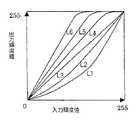
このようにして求めた評価値YHは、階調補正ルックアップテーブル(LUT)選択部14Fに出力される。階調補正LUT選択部14Fは、図6に示すように6つのLUT(L1〜L6)を有しており、入力する評価値YHの大きさに基づいて、例えば、次表、
【0029】
【表1】
【0030】
この処理におけるオートセットアップパラメータは、上記のようにして選択された階調補正LUTであり、この選択された階調補正LUTは、自動画像補正処理部15において階調補正LUTとして使用される。即ち、図4に示すように自動画像補正処理部15の階調補正LUT変換部15Bは、パラメータ決定部14によって決定された階調補正LUTに基づいてフレームメモリ13から入力する輝度信号Yを階調補正し、この階調補正した輝度信号Y’を出力する。
【0031】
図1において、自動画像補正処理部15によって補正された色差信号Cr', Cb'及び輝度信号Y’は、色信号変換部16に加えられ、ここでR、G、B信号に変換された後、Y、M、C(イエロー、マゼンタ、シアン)信号に変換され、又は直接Y、M、C信号に変換され、順次プリントエンジン17に送出される。
プリントエンジン17は、印画紙を搬送する手段、サーマルヘッド、定着ランプ等を有し、カラー画像をプリントする場合には、まず、印画紙を搬送するとともにY信号によってサーマルヘッドを制御し、印画紙のイエロー層を発色させ、続いて定着ランプによってイエローの発色を定着させる。印画紙のマゼンタ層及びシアン層の発色もM信号、C信号に基づいて同様に行われ、このようにして印画紙にカラー画像がプリントされる。
【0032】
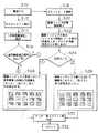
次に、上記構成のプリント装置10の動作について、図7に示すフローチャートを参照しながら説明する。
プリント装置10の電源がONされると(ステップS10)、カスタムモードとプリントモードの選択ができるようになっている。カスタムモードが選択されると(ステップS12)、各種の指定が可能となり、「連写画質補正」を選択すると、後述する「連写画質補正固定」が指定される(ステップS14、S16)。尚、「連写画質補正」を選択しない場合には、「連写画質補正固定」を行わない処理(即ち、連写画像であってもパラメータを固定しない処理)が指定されることになる。
【0033】
また、このカスタムモードでは、前述した一連の入力画像が連写画像か否かを判別するための条件の指定や、パラメータを固定する際にコマの選択基準の指定することもできる。
一方、プリントモードが選択され、画像ファイル記憶媒体22がカードスロットに挿入されると(ステップS18、ステップS20)、この画像ファイル記憶媒体22に記録された複数のコマ画像を一覧表示するための画像データを読み取り、画像インデックスを外部モニタやプリンタ内蔵液晶モニタ等に表示する(ステップS22)。尚、画像インデックスは、ファイル日時順にソート表示され、ステップS26、S28に示すように15コマが一覧表示される。また、16コマ目以降のコマは、次面を表示させることによって表示することができる。
【0034】
ステップS24では、カスタムモードで▲1▼側の「連写画質補正固定」が選択されているか否かが判別され、「連写画質補正固定」が選択されている場合には、ステップS26に進む。ステップS26では、画像インデックス表示された各コマが連写画像か否かを判断し、連写画像と判断したコマ画像を、他の画像と区別可能な「太ワク」又は「色ワク」で縁取りして表示する。従って、操作者は、これらの縁取りによって連写画像と他の画像とを識別することができる。
【0035】
いま、操作者が上記画像インデックスを用いてプリントコマをテンキー等で指定し、実行ボタンでプリントを行わせると(ステップS30)、指定されたコマに対応する画像データ及びその付加情報を画像ファイル記憶媒体22に格納された画像ファイルから取り込み、前述したパラメータの決定や画像補正等を行ったったのちコマ画像をプリントする(ステップS32)。尚、ステップS26において、一連の連写画像がプリント指定されると、連写画像の各画像データは同一のパラメータに基づいて画質補正される。
【0036】
一方、ステップS24において、カスタムモードで▲2▼側が選択されている場合には、ステップS28に進む。ステップS28では、画像インデックス表示された各コマを、連写画像か他の画像によって区別せずに表示する。そして、この場合には、画像インデックス表示された各コマが連写画像か否かの判断も行わない。更に、この画像インデックスを用いてプリントコマを指定し(ステップS30)、そのコマ画像をプリントする場合にも連写画像と他の画像とを区別せずにプリントする。即ち、一連の連写画像をプリントする場合であっても各コマごとにそれぞれパラメータを決定し、その決定したパラメータに基づいて各コマごとに画質補正等が行われる。
【0037】
尚、この実施の形態のプリント装置は、電子スチルカメラで生成した画像ファイルから画像データや付加情報を取り込むようにしたが、これに限らず、撮影付加情報の記録可能な銀塩フイルムからフイルムスキャナー等で画像データや付加情報を直接的に又は間接的に取り込むようにしてもよい。
また、この実施の形態では、一連の画像を連写画像としたが、これに限らず、例えばパノラマ画像でもよい。即ち、近年、複数枚の連続したコマ画像からなるパノラマ画像を良好に撮影することができるカメラが提案されている。このようなパノラマ画像を構成する一連の画像を、画像合成せずに各コマごとにプリントする場合には、連写画像と同様にパラメータを固定してプリントする。
【0038】
更に、本発明が適用されるプリント装置はこの実施の形態のものに限定されず、要はプリントする入力画像に基づいて自動画像補正処理を行って入力画像をプリントするものであれば、いかなるものにも適用できる。また、パラメータの種類もこの実施の形態に限定されない。
【0039】
【発明の効果】
以上説明したように本発明によれば、プリントする入力画像に基づいて自動画像補正処理を行って入力画像をプリントすることができるとともに、相互に関連性をもった一連の画像をプリントする場合には、自動画像補正処理のパラメータを固定するようにしたため、一連の画像間において色・階調・グレイバランスなどが変化しない安定したプリントを得ることができる。
【図面の簡単な説明】
【図1】本発明に係るプリント装置の実施の形態を示すブロック図
【図2】図1に示したパラメータ決定部及び自動画像補正処理部の具体例を示すブロック図
【図3】図2に示したWB補正係数テーブルの一例を示す図
【図4】図1に示したパラメータ決定部及び自動画像補正処理部の他の具体例を示すブロック図
【図5】図4に示したエリア平均輝度算出部でそれぞれ算出される各エリアを示す図
【図6】図4に示した階調補正LUT選択部によって選択される6つの階調補正LUTを示す図
【図7】図1のプリント装置の動作を説明するために用いてフローチャート
【符号の説明】
10…プリント装置
11…画像解凍処理部
12…付加情報読取部
13…フレームメモリ
14…パラメータ決定部
15…自動画像補正処理部
16…色信号変換部
17…プリントエンジン
20…電子スチルカメラ
22…画像ファイル記憶媒体[0001]
BACKGROUND OF THE INVENTION
The present invention relates to a printing method and apparatus, and more particularly to a printing method and apparatus for determining parameters for automatic image correction processing based on an input image to be printed, and automatically correcting and printing the input image based on the determined parameters.
[0002]
[Prior art]
Conventional printing devices such as digital printers compensate for differences in color and gradation between camera models, and have inappropriate brightness due to problems with automatic exposure adjustment (AE) and automatic white balance adjustment (AWB) on the camera side.・ Many of them have an auto setup function that automatically corrects images taken with white balance to the desired image quality.
[0003]
In addition, a gradation correction apparatus (mainly a gradation correction apparatus for a video printer) that automatically determines a scene characteristic (backlight, forward light, etc.) from an input image and corrects the gradation has been proposed (Japanese Patent Laid-Open No. Hei 8-). No. 62741).
On the other hand, when high-speed continuous shooting is performed with an electronic still camera, images are captured with the color balance state of each frame fixed, so that even if a highly saturated subject passes during high-speed continuous shooting, color balance for each frame There has been proposed one that can obtain a continuous shot image with no change (Japanese Patent Laid-Open No. 62-274889).
[0004]
[Problems to be solved by the invention]
By the way, when shooting a series of continuous shot images, even if you take a series of stable images by fixing the shooting conditions such as the color balance status of each frame on the camera side, On the other hand, if the parameters for automatic image correction processing are determined frame by frame and correction is performed frame by frame, for example, a highly saturated subject passes through the continuous shot image, or the positional relationship between clouds and the blue sky is constantly changing. If it has changed, there is a problem that a print in which the color, gradation, and gray balance are changed for each frame is completed.
[0005]
The present invention has been made in view of such circumstances, and when printing a series of mutually related images, a stable print in which color, gradation, gray balance, etc. do not change between the series of images. It is an object of the present invention to provide a printing method and apparatus capable of obtaining the above.
[0006]
[Means for Solving the Problems]
In order to achieve the above object, the invention according to
[0007]
As described in claim 2 of the present application, it is characterized in that a condition for discriminating the series of images can be designated.
[0008]
The automatic image correction processing parameters determined for the series of images are the parameters determined based on the first frame image of the series of images as shown in claim 3 of the present invention, and the first of the series of images to be printed. Parameters determined based on each frame image, the average value of parameters obtained for each frame of a series of images, the average value of parameters determined for each frame of a continuous image to be printed, and specified in the continuous image Any one of the parameters determined based on the frame image is used. The series of images is a continuous image or a panoramic image composed of a plurality of frames.
[0009]
The printing apparatus according to
[0010]
The invention according to claim 6 includes a correction mode for fixing parameters for automatic image correction processing in the case of the series of images, and a correction for determining parameters for automatic image correction processing for each image even in the case of the series of images. And a selection means for selecting these correction modes.
[0011]
DETAILED DESCRIPTION OF THE INVENTION
Hereinafter, preferred embodiments of a printing method and apparatus according to the present invention will be described in detail with reference to the accompanying drawings.
FIG. 1 is a block diagram showing an embodiment of a printing apparatus according to the present invention.
As shown in the figure, the
[0012]
The
[0013]
The electronic
[0014]
The luminance signal Y and the color difference signals Cr and Cb are obtained from the following equations based on the R, G, and B signals.
[0015]
[Expression 1]
Y = 0.299R + 0.587G + 0.114B
Cr = 0.713 * (R−Y)
Cb = 0.564 * (BY)
(However, R, G and B are integers from 0 to 255)
In addition, the electronic still
[0016]
When the image
[0017]
The additional
The
[0018]
Further, the
The
[0019]
(1) When “continuous shooting information” is included in the additional information input from the additional
(2) When the “continuous shooting information” is included in the additional information and the “shooting time interval is equal to or smaller than a predetermined threshold value”, it is determined that the image is a continuously shot image whose parameters are fixed.
(3) When “continuous shooting information” is included in the additional information, “the shooting time interval is equal to or less than a predetermined threshold”, and “exposure setting is manual” and / or “lens F value and shutter speed are fixed” It is determined that the image is a continuous shot image whose parameters are fixed to.
[0020]
(4) In the case of an electronic still camera that cannot record continuous shooting information in the additional information, “the shooting time interval is equal to or less than a predetermined threshold value” and “exposure setting is manual” and / or “lens F value, When the shutter speed is “fixed”, it is determined that the image is a continuous shot image whose parameters are fixed.
The
[0021]
(1) A parameter to be fixed is determined based on the first frame image among the continuous shot images.
(2) A parameter to be fixed is determined based on the first frame image of the continuous shot images to be printed.
(3) The average value of the parameters obtained for each frame of the continuous shot image is a fixed parameter.
[0022]
(4) The average value of the parameters obtained for each frame of the continuous shot image to be printed is a fixed parameter.
(5) A fixed parameter is determined based on the frame image designated in the continuous shot image.
The automatic image
[0023]
Next, a parameter determination method by the
First, when determining parameters for AWB, the
[0024]
The
[0025]
As shown in FIG. 2, the calculation unit 15A of the automatic image
[0026]
[Expression 2]
Cr '= Cr-CrH
Cb '= Cb-CbH
The processed color difference signals Cr ′ and Cb ′ are output as shown in FIG.
On the other hand, when determining the parameters for gradation correction, the
[0027]
The average
[0028]
[Equation 3]
YH = 0.5YA + 0.25 × YB + 0.175 × YC + 0.075 × YD
The evaluation value YH for evaluating the brightness is obtained by performing a weighting calculation as shown in FIG.
The evaluation value YH obtained in this way is output to the gradation correction lookup table (LUT)
[0029]
[Table 1]
[0030]
The auto setup parameter in this process is the gradation correction LUT selected as described above, and this selected gradation correction LUT is used as the gradation correction LUT in the automatic image
[0031]
In FIG. 1, the color difference signals Cr ′ and Cb ′ and the luminance signal Y ′ corrected by the automatic image
The
[0032]
Next, the operation of the
When the power of the
[0033]
In this custom mode, it is also possible to specify conditions for determining whether or not the above-described series of input images are continuous shot images, and to specify frame selection criteria when fixing parameters.
On the other hand, when the print mode is selected and the image
[0034]
In step S24, it is determined whether “continuous shooting image quality correction fixed” on the (1) side is selected in the custom mode. If “continuous shooting image quality correction fixed” is selected, the process proceeds to step S26. . In step S26, it is determined whether or not each frame displayed in the image index is a continuous shot image, and the frame image determined to be a continuous shot image is trimmed with “thick back” or “color back” that can be distinguished from other images. And display. Therefore, the operator can discriminate between the continuous shot image and the other images by these borders.
[0035]
Now, when the operator designates a print frame with the numeric keypad using the image index and causes the execution button to perform printing (step S30), image data corresponding to the designated frame and its additional information are stored in an image file. After taking in the image file stored in the medium 22 and performing the above-described parameter determination and image correction, the frame image is printed (step S32). In step S26, when a series of continuous shot images are designated for printing, the image data of the continuous shot images is corrected based on the same parameters.
[0036]
On the other hand, if the (2) side is selected in the custom mode in step S24, the process proceeds to step S28. In step S28, each frame displayed in the image index is displayed without being distinguished depending on whether it is a continuous shot image or another image. In this case, it is not determined whether or not each frame displayed in the image index is a continuous shot image. Further, a print frame is designated using this image index (step S30), and even when the frame image is printed, the continuous shot image and the other image are printed without being distinguished. That is, even when a series of continuous shot images are printed, parameters are determined for each frame, and image quality correction is performed for each frame based on the determined parameters.
[0037]
The printing apparatus according to this embodiment captures image data and additional information from an image file generated by an electronic still camera. However, the present invention is not limited to this, and from a silver salt film capable of recording additional shooting information to a film scanner. For example, the image data and the additional information may be directly or indirectly captured.
In this embodiment, a series of images are taken as continuous shot images. That is, in recent years, a camera that can satisfactorily capture a panoramic image composed of a plurality of continuous frame images has been proposed. When printing a series of images constituting such a panoramic image for each frame without image synthesis, the parameters are fixed and printed in the same manner as the continuous shot images.
[0038]
Further, the printing apparatus to which the present invention is applied is not limited to the one in this embodiment. In short, any printing apparatus that prints an input image by performing automatic image correction processing based on the input image to be printed can be used. It can also be applied to. Also, the types of parameters are not limited to this embodiment.
[0039]
【The invention's effect】
As described above, according to the present invention, when an input image can be printed by performing automatic image correction processing based on the input image to be printed, and when a series of images having mutual relations are printed, Since the parameters of the automatic image correction processing are fixed, it is possible to obtain a stable print in which color, gradation, gray balance and the like do not change between a series of images.
[Brief description of the drawings]
FIG. 1 is a block diagram illustrating an embodiment of a printing apparatus according to the present invention. FIG. 2 is a block diagram illustrating a specific example of a parameter determination unit and an automatic image correction processing unit illustrated in FIG. FIG. 4 is a block diagram showing another specific example of the parameter determination unit and the automatic image correction processing unit shown in FIG. 1. FIG. 5 is a block diagram showing an example of the WB correction coefficient table shown in FIG. FIG. 6 is a diagram showing each area calculated by the calculation unit. FIG. 6 is a diagram showing six tone correction LUTs selected by the tone correction LUT selection unit shown in FIG. 4. FIG. Flow chart used to explain the operation 【Explanation of symbols】
DESCRIPTION OF
Claims (6)
Translated fromJapaneseプリントする複数コマの入力画像が、各コマの撮影条件が固定されて撮影された一連の画像であるか否かを、一連の画像であることを示す付加情報とともに各コマの撮影時間間隔が所定値以下であることを読み取った場合、各コマの撮影時間間隔が所定値以下であり且つ露出が固定されていたことを読み取った場合、前記付加情報とともに各コマの撮影時間間隔が所定値以下であり且つ露出が固定されていたことを読み取った場合のうちのいずれかによって判別し、
複数コマの入力画像が一連の画像であることが判別されると、複数コマの入力画像のうちの少なくとも1つの画像に基づいて自動画像補正処理のパラメータを決定するとともに該決定したパラメータを固定し、
プリントする一連の画像の補正処理に同一のパラメータを使用することを特徴とするプリント方法。In a printing method for determining parameters of automatic image correction processing based on an input image to be printed, correcting the input image based on the determined parameters, and printing.
Whether or not the input images of a plurality of frames to be printed are a series of images shot with the shooting conditions of each frame fixed,together with additional information indicating that it is a series of images, the shooting time interval of each frame is predetermined. If it is read that the shooting time interval of each frame is equal to or less than the predetermined value and the exposure is fixed, the shooting time interval of each frame is equal to or less than the predetermined value together with the additional information. It is discriminated byany of the cases where it was read that the exposure was fixed and
When it is determined that the input image of a plurality of frames is a series of images, a parameter for automatic image correction processing is determined based on at least one of the input images of the plurality of frames, and the determined parameter is fixed. ,
A printing method, wherein the same parameter is used for correction processing of a series of images to be printed.
入力画像に基づいて自動画像補正処理のパラメータを決定するパラメータ決定手段であって、前記判別手段によって入力画像が一連の画像であることが判別されると、該一連の画像の各画像の処理に共通に使用する自動画像補正処理のパラメータを決定するパラメータ決定手段と、
前記パラメータ決定手段によって決定されたパラメータに基づいて入力画像を補正処理する処理手段と、
前記処理手段によって処理された画像をプリントするプリント手段と、
を備えたことを特徴とするプリント装置。Discriminating means for discriminating whether or not the input images of a plurality of frames to be printed are a series of images shot with the shooting conditions of each frame fixed, andeach additional information indicating that it is a series of images. When reading that the shooting time interval of a frame is less than or equal to a predetermined value, when reading that the shooting time interval of each frame is less than or equal to a predetermined value and the exposure is fixed, A discriminating means for discriminating by any of the cases where the time interval is equal to or less than a predetermined value and the exposure is fixed ;
Parameter determining means for determining parameters for automatic image correction processing based on an input image, and when the determining means determines that the input image is a series of images, processing of each image in the series of images is performed. Parameter determining means for determining parameters of automatic image correction processing used in common;
Processing means for correcting the input image based on the parameters determined by the parameter determination means;
Printing means for printing the image processed by the processing means;
A printing apparatus comprising:
Priority Applications (2)
| Application Number | Priority Date | Filing Date | Title |
|---|---|---|---|
| JP26499598AJP3728744B2 (en) | 1998-09-18 | 1998-09-18 | Printing method and apparatus |
| US09/395,786US6795212B1 (en) | 1998-09-18 | 1999-09-14 | Printing method and apparatus |
Applications Claiming Priority (1)
| Application Number | Priority Date | Filing Date | Title |
|---|---|---|---|
| JP26499598AJP3728744B2 (en) | 1998-09-18 | 1998-09-18 | Printing method and apparatus |
Publications (2)
| Publication Number | Publication Date |
|---|---|
| JP2000098514A JP2000098514A (en) | 2000-04-07 |
| JP3728744B2true JP3728744B2 (en) | 2005-12-21 |
Family
ID=17411113
Family Applications (1)
| Application Number | Title | Priority Date | Filing Date |
|---|---|---|---|
| JP26499598AExpired - Fee RelatedJP3728744B2 (en) | 1998-09-18 | 1998-09-18 | Printing method and apparatus |
Country Status (2)
| Country | Link |
|---|---|
| US (1) | US6795212B1 (en) |
| JP (1) | JP3728744B2 (en) |
Families Citing this family (16)
| Publication number | Priority date | Publication date | Assignee | Title |
|---|---|---|---|---|
| US7428011B1 (en)* | 1999-09-02 | 2008-09-23 | Fujifilm Corporation | Wide dynamic range electronic image recording and reproducing system |
| US7081918B2 (en)* | 2000-04-28 | 2006-07-25 | Fuji Photo Film Co., Ltd. | Image processing method, image processing apparatus and recording medium storing program therefor |
| WO2002065756A1 (en) | 2001-02-09 | 2002-08-22 | Seiko Epson Corporation | Apparatus and method for adjusting output image from image data |
| US7304668B2 (en)* | 2001-04-11 | 2007-12-04 | Fujifilm Corporation | Printer system and image processing system having image correcting function |
| JP4230129B2 (en)* | 2001-06-22 | 2009-02-25 | 富士フイルム株式会社 | Preview image output system, operation control method thereof, recording medium storing program, and program |
| US20040013405A1 (en)* | 2002-07-18 | 2004-01-22 | Christiansen Robert D | Method for preparing/printing video scene indices |
| US7684096B2 (en)* | 2003-04-01 | 2010-03-23 | Avid Technology, Inc. | Automatic color correction for sequences of images |
| JP4189654B2 (en)* | 2003-04-18 | 2008-12-03 | セイコーエプソン株式会社 | Image processing device |
| JP2006295581A (en)* | 2005-04-12 | 2006-10-26 | Olympus Corp | Imaging system and video signal processing program |
| JP2007108578A (en)* | 2005-10-17 | 2007-04-26 | Noritsu Koki Co Ltd | Apparatus, method and computer program for image processing |
| US20090153586A1 (en)* | 2007-11-07 | 2009-06-18 | Gehua Yang | Method and apparatus for viewing panoramic images |
| JP2010103692A (en)* | 2008-10-22 | 2010-05-06 | Canon Inc | Image output apparatus, image output method, and control program |
| JP2010130510A (en) | 2008-11-28 | 2010-06-10 | Brother Ind Ltd | Printing device and program |
| JP4692614B2 (en) | 2008-11-28 | 2011-06-01 | ブラザー工業株式会社 | Printing apparatus and program |
| JP4692615B2 (en) | 2008-11-28 | 2011-06-01 | ブラザー工業株式会社 | Printing apparatus and program |
| JP5343739B2 (en) | 2009-07-02 | 2013-11-13 | ブラザー工業株式会社 | Output device and program |
Family Cites Families (4)
| Publication number | Priority date | Publication date | Assignee | Title |
|---|---|---|---|---|
| JPH06101847B2 (en) | 1986-05-21 | 1994-12-12 | キヤノン株式会社 | Imaging device |
| US5467168A (en)* | 1992-11-18 | 1995-11-14 | Fuji Photo Film Co., Ltd. | Photograph printing method |
| JPH06258723A (en)* | 1993-03-08 | 1994-09-16 | Olympus Optical Co Ltd | Panoramic photographic processing system |
| JP3018914B2 (en) | 1994-08-23 | 2000-03-13 | 松下電器産業株式会社 | Gradation correction device |
- 1998
- 1998-09-18JPJP26499598Apatent/JP3728744B2/ennot_activeExpired - Fee Related
- 1999
- 1999-09-14USUS09/395,786patent/US6795212B1/ennot_activeExpired - Lifetime
Also Published As
| Publication number | Publication date |
|---|---|
| US6795212B1 (en) | 2004-09-21 |
| JP2000098514A (en) | 2000-04-07 |
Similar Documents
| Publication | Publication Date | Title |
|---|---|---|
| JP3725454B2 (en) | Output image adjustment for image files | |
| JP4775410B2 (en) | Output image adjustment of image data | |
| JP3849706B2 (en) | Automatic image quality adjustment according to the type of light source | |
| JP3011432B2 (en) | Color image processing equipment | |
| JP3728744B2 (en) | Printing method and apparatus | |
| US6952223B2 (en) | Image processing method and apparatus | |
| US6850271B1 (en) | Photographic apparatus | |
| JP2003204459A (en) | Digital camera and image reproducing apparatus | |
| EP1337104B1 (en) | Method, apparatus, and program for image processing | |
| JP4045929B2 (en) | Automatic image quality adjustment according to subject size | |
| JP2004088345A (en) | Image forming method, image processor, print preparation device, and storage medium | |
| JP3520869B2 (en) | Image output adjustment of image data | |
| JP2003060935A (en) | Output image adjustment method for image file | |
| JP4266716B2 (en) | Output image adjustment for image files | |
| JP4015066B2 (en) | Output image adjustment for image files | |
| JP3834516B2 (en) | Output image adjustment of image data | |
| JP5045808B2 (en) | Output image adjustment for image files | |
| JP4509499B2 (en) | Image processing device | |
| JP3999157B2 (en) | Output image adjustment for image files | |
| JP4126967B2 (en) | Output image adjustment of image data | |
| JPH06178113A (en) | Image data preservation and conversion device and device for calculating image representative value | |
| JP2003108986A (en) | Output image adjustment of image data | |
| HK1056657A (en) | Method, apparatus, and program for image processing | |
| JP2000083167A (en) | Image processor |
Legal Events
| Date | Code | Title | Description |
|---|---|---|---|
| A621 | Written request for application examination | Free format text:JAPANESE INTERMEDIATE CODE: A621 Effective date:20040810 | |
| A977 | Report on retrieval | Free format text:JAPANESE INTERMEDIATE CODE: A971007 Effective date:20050623 | |
| A131 | Notification of reasons for refusal | Free format text:JAPANESE INTERMEDIATE CODE: A131 Effective date:20050628 | |
| A521 | Request for written amendment filed | Free format text:JAPANESE INTERMEDIATE CODE: A523 Effective date:20050826 | |
| TRDD | Decision of grant or rejection written | ||
| A01 | Written decision to grant a patent or to grant a registration (utility model) | Free format text:JAPANESE INTERMEDIATE CODE: A01 Effective date:20050912 | |
| A61 | First payment of annual fees (during grant procedure) | Free format text:JAPANESE INTERMEDIATE CODE: A61 Effective date:20050925 | |
| R150 | Certificate of patent or registration of utility model | Free format text:JAPANESE INTERMEDIATE CODE: R150 | |
| FPAY | Renewal fee payment (event date is renewal date of database) | Free format text:PAYMENT UNTIL: 20081014 Year of fee payment:3 | |
| S111 | Request for change of ownership or part of ownership | Free format text:JAPANESE INTERMEDIATE CODE: R313111 | |
| FPAY | Renewal fee payment (event date is renewal date of database) | Free format text:PAYMENT UNTIL: 20081014 Year of fee payment:3 | |
| R350 | Written notification of registration of transfer | Free format text:JAPANESE INTERMEDIATE CODE: R350 | |
| FPAY | Renewal fee payment (event date is renewal date of database) | Free format text:PAYMENT UNTIL: 20091014 Year of fee payment:4 | |
| FPAY | Renewal fee payment (event date is renewal date of database) | Free format text:PAYMENT UNTIL: 20101014 Year of fee payment:5 | |
| FPAY | Renewal fee payment (event date is renewal date of database) | Free format text:PAYMENT UNTIL: 20111014 Year of fee payment:6 | |
| FPAY | Renewal fee payment (event date is renewal date of database) | Free format text:PAYMENT UNTIL: 20121014 Year of fee payment:7 | |
| FPAY | Renewal fee payment (event date is renewal date of database) | Free format text:PAYMENT UNTIL: 20121014 Year of fee payment:7 | |
| FPAY | Renewal fee payment (event date is renewal date of database) | Free format text:PAYMENT UNTIL: 20131014 Year of fee payment:8 | |
| R250 | Receipt of annual fees | Free format text:JAPANESE INTERMEDIATE CODE: R250 | |
| R250 | Receipt of annual fees | Free format text:JAPANESE INTERMEDIATE CODE: R250 | |
| R250 | Receipt of annual fees | Free format text:JAPANESE INTERMEDIATE CODE: R250 | |
| R250 | Receipt of annual fees | Free format text:JAPANESE INTERMEDIATE CODE: R250 | |
| LAPS | Cancellation because of no payment of annual fees |