JP3727757B2 - Composite operation type electric parts - Google Patents
Composite operation type electric partsDownload PDFInfo
- Publication number
- JP3727757B2 JP3727757B2JP17966297AJP17966297AJP3727757B2JP 3727757 B2JP3727757 B2JP 3727757B2JP 17966297 AJP17966297 AJP 17966297AJP 17966297 AJP17966297 AJP 17966297AJP 3727757 B2JP3727757 B2JP 3727757B2
- Authority
- JP
- Japan
- Prior art keywords
- ring
- conductive plate
- holding body
- notch
- operation ring
- Prior art date
- Legal status (The legal status is an assumption and is not a legal conclusion. Google has not performed a legal analysis and makes no representation as to the accuracy of the status listed.)
- Expired - Lifetime
Links
- 239000002131composite materialSubstances0.000titleclaimsdescription14
- 238000005286illuminationMethods0.000claimsdescription2
- 229920003002synthetic resinPolymers0.000description8
- 239000000057synthetic resinSubstances0.000description8
- 239000000758substrateSubstances0.000description3
- 239000004925Acrylic resinSubstances0.000description2
- 229920000178Acrylic resinPolymers0.000description2
- 238000001514detection methodMethods0.000description2
- 230000000694effectsEffects0.000description2
- 230000007935neutral effectEffects0.000description2
- 239000012780transparent materialSubstances0.000description2
- 239000002184metalSubstances0.000description1
- 230000002093peripheral effectEffects0.000description1
Images

Landscapes
- Switches With Compound Operations (AREA)
- Switch Cases, Indication, And Locking (AREA)
- Rotary Switch, Piano Key Switch, And Lever Switch (AREA)
Description
Translated fromJapanese【0001】
【発明の属する技術分野】
本発明は、多方向スイッチの外側にロータリスイッチやロータリボリューム等の回転型電気部品を組み込んだ複合操作型電気部品に係り、特に、その照光構造に関する。
【0002】
【従来の技術】
従来より、実開昭57−80029号公報に開示されているように、内側に配置された4個の押釦スイッチと外側に配置されたロータリスイッチとを一体的に組み込んだ複合操作型電気部品が知られている。この複合操作型電気部品は、各押釦スイッチの中央に配置された光源によって押釦スイッチのつまみが照光されるようになっており、各押釦スイッチのプッシュ動作に応じた4方向の位置検出と、ロータリスイッチの回転動作に応じた連続的な信号検出を行なうことができる。
【0003】
【発明が解決しようとする課題】
ところで、前述した従来の複合操作型電気部品では、内側の電気部品として互いに独立した4個の押釦スイッチを用いているため、押釦スイッチの操作性が悪く、全体形状が大型化する等の難点がある。そこで、内側の電気部品として多方向スイッチを用い、この多方向スイッチの外側に回転型電気部品を組み込んだ複合操作型電気部品が考えられる。このような複合操作型電気部品によれば、多方向スイッチに備えられる操作レバーの傾倒動作に応じて数種類の切り換え信号を出力することができるのみならず、操作レバーのプッシュ動作に応じて別の切り換え信号を出力することができ、操作性の向上や小型化を図ることができる。
【0004】
しかしながら、周知のように、多方向スイッチはその中央に傾倒自在な操作レバーを具備しているため、操作レバーの上端に取り付けられたつまみを照光する場合、多方向スイッチの中央に光源を配置することができず、仮につまみの真下に光源を配置するスペースを確保したとしても、光源の外側に回転型電気部品の操作リングを回転自在に配置しなければならないため、光源に電源を供給することが困難になるという問題が発生する。
【0005】
【課題を解決するための手段】
本発明は、回転型電気部品の操作リングにLEDを接続した第1および第2の導電板を固定し、これら導電板に設けられた互いに逆向きの摺動子を一対の給電板で挟持することとする。このように構成すると、操作リングと一体的に回転するLEDに給電板から摺動子と導電板を介して電源が供給されるため、多方向スイッチの操作レバーに取り付けられたつまみ等を照光することができる。
【0006】
【発明の実施の形態】
本発明の複合操作型電気部品では、操作レバーの傾倒動作に応じた信号を出力する多方向スイッチと、この多方向スイッチの外側に配置された操作リングの回転動作に応じた信号を出力する回転型電気部品とを具備し、前記操作リングには径方向に切り欠いて切欠きを形成してあると共に、内部に保持体を収納し、前記保持体には突部が形成され、該突部が前記切欠きに嵌め込まれて前記操作リングに保持されると共に、前記操作レバーを挿通する貫通孔を有し、第1の導電板は前記保持体に保持され、一部が前記操作リングの前記切欠きを通して前記操作リングの外側に延びた延出部分に下向きの摺動子が形成され、第2の導電板は前記保持体に保持され、一部が前記操作リングの前記切欠きを通して前記操作リングの外側に延びた延出部分に上向きの摺動子が形成され、一対の給電板は前記操作リングの外側に配置され、前記操作レバーはつまみを有し、前記保持体に一体化された前記第1の導電板と前記第2の導電板とを、前記切欠きに通して保持して前記操作リングに固定すると共に、前記操作リングの内側にある前記第1および第2の導電板間に前記操作レバーのつまみを照光するLEDを接続し、かつ、前記操作リングの外側にある前記両摺動子を前記一対の給電板で挟持した。
【0007】
前記回転型電気部品としてロータリスイッチやロータリボリューム等の操作リングが回転する電気部品を用いることができ、また、操作リングは360度以内の有限回転でも360度以上の無限回転でも良い。
【0008】
また、前記操作リングの一部に前記第1および第2の導電板が挿通する切欠きを形成すると、操作リングに対して両導電板を簡単に一体化することができるばかりでなく、LEDと給電板を操作リングの内外に振り分けて小型化を図ることができる。
【0009】
【実施例】
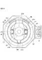
実施例について図面を参照して説明すると、図1は複合操作型電気部品の断面図、図2は複合操作型電気部品の要部を示す平面図である。
【0010】
実施例に係る複合操作型電気部品は内側の多方向スイッチと外側のロータリボリュームとで構成されており、これら多方向スイッチとロータリボリュームは後述するように一体化されている。
【0011】
内側の多方向スイッチは、上面を開口する合成樹脂製の内側ハウジング1と、内側ハウジング1の開口端に被着された合成樹脂製の蓋体2と、内側ハウジング1の内部から蓋体2を通って上方へ突出する金属製の操作レバー3とを具備しており、操作レバー3の上端に内側つまみ4が取り付けられている。内側ハウジング1の内底面に第1の固定接点5とコモン接点6が配設され、コモン接点6上に第1の固定接点5と接離する第1の可動接点板7が載置されており、これら第1の固定接点5と第1の可動接点板7とで1つの常開スイッチS1が構成されている。第1の可動接点板7と操作レバー3の下端との間に押圧片8と緩衝ゴム9が介設されている。操作レバー3の外側に合成樹脂製の駆動体10が嵌合されており、これら操作レバー3と駆動体10はスプライン結合されて軸線方向のみ相対移動できるようになっている。駆動体10に第2の可動接点板11が固定されており、第2の可動接点板11は導電性のコイルばね12の付勢力によって蓋体2の下面に圧接されている。蓋体2の下面に複数、例えば8つの第2の固定接点13が周方向に所定間隔を保って配設されており、これら第2の固定接点13群と第2の可動接点板11とで8つの常閉スイッチS2が構成され、各常閉スイッチS2と常開スイッチS1はコイルばね12を介して導通されている。
【0012】
このように構成された多方向スイッチにおいて、内側つまみ4によって操作レバー3を図1の中立位置から任意方向へ傾倒すると、第2の可動接点板11が傾倒方向の反対側に位置する1つの第2の固定接点13を支点として回動し、8個の常閉スイッチS2のうち1つだけオンしたまま残りが全てオフになる。さらに操作レバー3を同方向へ傾倒すると、操作レバー3の下端が緩衝ゴム9と押圧片8を介して第1の可動接点板7を押圧し、第1の可動接点板7が第1の固定接点5に接触した時点で常開スイッチS1がオンになる。その結果、常開スイッチS1と1つの常閉スイッチS2との間に導通路が形成されるため、例えば、第1の固定接点5と各第2の固定接点13間の出力信号をマイコンに取り込めば、どの第2の固定接点13からオン信号が出力されるかによって操作レバー3の傾倒方向を判定できる。一方、操作レバー3を図1の中立位置で押し込むと、駆動体10と第2の可動接点板11は移動せず、操作レバー3のみが真下に移動して緩衝ゴム9と押圧片8を介して第1の可動接点板7を押圧する。そして、第1の可動接点板7が第1の固定接点5に接触した時点で、常開スイッチS1と全ての常閉スイッチS2との間に導通路が形成されるため、各第2の固定接点13からの8つのオン信号に基づいてマイコンが操作レバー3のプッシュ動作を検出できる。
【0013】
外側のロータリボリュームは、合成樹脂製の外側ハウジング14と、外側ハウジング14の外周縁に一体化された円筒状のカバー15とを具備しており、外側ハウジング14は多方向スイッチの内側ハウジング1の外側面に圧入等により固定されている。外側ハウジング14とカバー15とで切欠きを有するリング状の凹溝が画成され、この凹溝の内底面に前記切欠きから端子が設けられた一端を突出させた抵抗基板16が載置されており、抵抗基板16の上面に抵抗体17が形成されている。外側ハウジング14に合成樹脂製の操作リング18が回転可能に保持されており、操作リング18の回転角度はストッパ18aによって例えば約300度に規制されている。操作リング18の下面に摺動子20が取り付けられており、摺動子20は抵抗基板16の抵抗体17に弾接している。
【0014】
操作リング18の上端に外側つまみ21が取り付けられており、外側つまみ21の凹部内に多方向スイッチの内側つまみ4が位置している。操作リング18の内側に合成樹脂製の保持体22が配置されており、操作リング18の上端に形成された一対のすり割状切欠き18bに保持体22の周縁に形成された一対の突部22aを圧入することにより、保持体22は操作リング18に固定されている。図2に示すように、保持体22の中央に貫通孔22bが形成されており、多方向スイッチの操作レバー3は貫通孔22bを挿通して上方へ延びている。保持体22に第1ないし第3の導電板23〜25がアウトサートにより固定されており、これら導電板23〜25は貫通孔22bの外側に環状に配置されている。第1の導電板23と第2の導電板24は一方の切欠き18bを通って操作リング18の外側へ延びており、この延出部分において第1の導電板23には下向きの摺動子23aが、第2の導電板24には上向きの摺動子24aが形成されている。第1の導電板23と第3の導電板25との間、および第2の導電板24と第3の導電板25との間にそれぞれLED26が搭載されており、これらLED26は第3の導電板25を介して直列に接続されている。
【0015】
外側ハウジング14とカバー15の上端に合成樹脂製の第1の環状体27が載置されており、第1の環状体27の上面にリング状の第1の給電板28がアウトサートにより固定されている。第1の給電板28の一部はカバー15の外側に沿って外側ハウジング14の下面に折り曲げられており、これにより第1の環状体27は外側ハウジング14に固定されている。第1の環状体27の下面にクリックばね19が取り付けられ、操作リング18の上面に図示せぬカム山が形成されており、クリックばね19がカム山と係脱することによりクリック感触が生起される。第1の環状体27の上面に合成樹脂製の第2の環状体29が載置されており、第2の環状体29の下面にリング状の第2の給電板30がアウトサートにより固定されている。第2の給電板30の一部もカバー15の外側に沿って外側ハウジング14の下面に折り曲げられており、これにより第2の環状体29は外側ハウジング14に固定されている。第1の給電板28と第2の給電板30は所定間隔を保って対向しており、この間隔の内部で第1の導電板23の摺動子23aは第1の給電板28の上面に弾接し、第2の導電板24の摺動子24aは第2の給電板30の下面に弾接している。
【0016】
このように構成されたロータリボリュームにおいて、外側つまみ21によって操作リング18を正逆いずれかの方向へ回転すると、クリックばね19とカム山との係脱によりクリック感触が生起されると共に、摺動子20が抵抗体17上を摺動して、操作リング18の回転量に応じた抵抗値変化が出力される。また、操作リング18の回転に連動して第1の導電板23の摺動子23aが第1の給電板28の上面を摺動し、第2の導電板24の摺動子24aが第2の給電板30の下面を摺動し、第1の給電板28と第2の給電板30との間に第1の導電板23、一方のLED26、第3の導電板25、他方のLED26、第2の導電板24という導電路が確保されるため、第1の給電板28と第2の給電板30との間に電流を流すと両LED26が点灯する。したがって、内側つまみ4をアクリル樹脂等の透明材料で形成すれば、LED26からの光によって内側つまみ4を照光させることができる。また、外側つまみ21をアクリル樹脂等の透明材料で形成すれば、外側つまみ21を照光させることができ、この場合には、LED26が外側つまみ21と共に回転するため、LED26を配置した上方に表示部を設け、これを照光する場合に適している。
【0017】
なお、内側の多方向スイッチの構造は上記実施例に限定されず、操作レバーの傾倒動作に応じて位置信号を出力するものであれば良い。また、外側の回転型電気部品も上記実施例のロータリボリュームに限定されず、操作リングがエンドレスで回転するロータリエンコーダに置換することも可能であり、その場合、第1および第2の給電板28,30はリング状であるから、摺動子23a,24aが常時これと摺接することになる。
【0018】
また、上記実施例では、2個のLED26を点灯させるために第1ないし第3の導電板23〜25を用いているが、LED26の数は2個に特定されるものでなく、例えば1個のLED26を点灯させる場合は、第1の導電板23と第2の導電板24との間にLED26を接続すれば良く、3個以上のLED26を点灯させる場合は、第3の導電板25の数を増やせば良い。
【0019】
【発明の効果】
本発明は、以上説明したような形態で実施され、以下に記載されるような効果を奏する。
【0020】
操作レバーの傾倒動作に応じた信号を出力する多方向スイッチと、この多方向スイッチの外側に配置された操作リングの回転動作に応じた信号を出力する回転型電気部品とを具備し、操作リングには径方向に切り欠いて切欠きを形成してあると共に、内部に保持体を収納し、保持体には突部が形成され、該突部が切欠きに嵌め込まれて操作リングに保持されると共に、操作レバーを挿通する貫通孔を有し、第1の導電板は保持体に保持され、一部が操作リングの切欠きを通して操作リングの外側に延びた延出部分に下向きの摺動子が形成され、第2の導電板は保持体に保持され、一部が操作リングの切欠きを通して操作リングの外側に延びた延出部分に上向きの摺動子が形成され、一対の給電板は操作リングの外側に配置され、操作レバーはつまみを有し、保持体に一体化された第1の導電板と第2の導電板とを、切欠きに通して保持して操作リングに固定すると共に、操作リングの内側にある第1および第2の導電板間に操作レバーのつまみを照光するLEDを接続し、かつ、操作リングの外側にある両摺動子を一対の給電板で挟持したため、操作リングの内側で操作リングと一体的に回転するLEDに、操作リングの外側で給電板から摺動子と導電板を介して電源が供給されるので、多方向スイッチの操作レバーのつまみを照光することができ、かつ操作リングに対して両導電板を簡単に一体化することができるばかりでなく、LEDと給電板を操作リングの内外に振り分けて小型化を図ることができる。
【0021】
また、複数のLEDを接続したため、操作レバーのつまみを均一に照光できる。
【図面の簡単な説明】
【図1】実施例に係る複合操作型電気部品の断面図である。
【図2】該複合操作型電気部品の要部を示す平面図である。
【符号の説明】
1 内側ハウジング
3 操作レバー
4 内側つまみ4
14 外側ハウジング
18 操作リング
18b 切欠き
21 外側つまみ
22 保持体
22a 突部
22b 貫通孔
23 第1の導電板
23a 摺動子
24 第2の導電板
24a 摺動子
25 第3の導電板
27 第1の環状体
28 第1の給電板
29 第2の環状体
30 第2の給電板[0001]
BACKGROUND OF THE INVENTION
The present invention relates to a composite operation type electrical component in which a rotary type electrical component such as a rotary switch or a rotary volume is incorporated outside a multidirectional switch, and more particularly to an illumination structure thereof.
[0002]
[Prior art]
Conventionally, as disclosed in Japanese Utility Model Publication No. 57-80029, there is a composite operation type electric component in which four push button switches arranged on the inside and a rotary switch arranged on the outside are integrated. Are known. In this composite operation type electric component, the knob of the push button switch is illuminated by the light source arranged at the center of each push button switch, the position detection in four directions according to the push operation of each push button switch, and the rotary Continuous signal detection according to the rotational operation of the switch can be performed.
[0003]
[Problems to be solved by the invention]
By the way, in the conventional composite operation type electric parts described above, four push button switches independent from each other are used as the inner electric parts. Therefore, the operability of the push button switches is poor and the overall shape is increased. is there. In view of this, a multi-operation type electrical component in which a multi-directional switch is used as an inner electrical component and a rotary electrical component is incorporated outside the multi-directional switch can be considered. According to such a composite operation type electrical component, not only can several kinds of switching signals be output according to the tilting operation of the operation lever provided in the multi-directional switch, but another operation signal can be output according to the push operation of the operation lever. A switching signal can be output, and the operability can be improved and the size can be reduced.
[0004]
However, as is well known, the multidirectional switch has an operation lever that can be tilted at the center thereof. Therefore, when a knob attached to the upper end of the operation lever is illuminated, a light source is arranged at the center of the multidirectional switch. Even if there is a space for the light source to be placed directly under the knob, the operating ring of the rotating electrical component must be rotatably arranged outside the light source. The problem that becomes difficult occurs.
[0005]
[Means for Solving the Problems]
In the present invention, first and second conductive plates connected to LEDs are fixed to an operation ring of a rotating electrical component, and oppositely provided sliders provided on these conductive plates are sandwiched between a pair of power supply plates. I will do it. With this configuration, power is supplied to the LED that rotates integrally with the operation ring from the power supply plate via the slider and the conductive plate, so that the knob attached to the operation lever of the multidirectional switch is illuminated. be able to.
[0006]
DETAILED DESCRIPTION OF THE INVENTION
In the composite operation type electrical component of the present invention, the multi-directional switch that outputs a signal according to the tilting operation of the operation lever, and the rotation that outputs a signal according to the rotation operation of the operation ring arranged outside the multi-directional switch Theoperation ring is cut out in a radial direction and has a cutout, and a holding body is housed therein, and a protrusion is formed on the holding body. Is fitted in the notch and held by the operating ring, and has a through hole through which the operating lever is inserted, the first conductive plate is held by the holding body, and a part of the operating ring A downward slider is formed in an extending portion extending outside the operation ring through the notch, the second conductive plate is held by the holding body, and part of the operation ring passes through the notch of the operation ring. An extension that extends outside the ring Upwards of the slider is formed, the pair of power supply plates arranged on the outside of the operating ring, said operating lever has a knob,thesaid first conductive platewhich is integrated in the holder first 2 conductive plates areheld through the notches and fixed to theoperation ring, and theknob of the operation lever is illuminated between the first and second conductive platesinside the operation ring. connect the LED, and is sandwiched between the two sliderson the outside of the operating ring bythe pair of feed plates.
[0007]
As the rotary electrical component, an electrical component such as a rotary switch or a rotary volume that rotates an operation ring can be used. The operation ring may be a finite rotation of 360 degrees or an infinite rotation of 360 degrees or more.
[0008]
In addition, when a notch through which the first and second conductive plates are inserted is formed in a part of the operation ring, not only the conductive plates can be easily integrated with the operation ring, but also the LED and It is possible to reduce the size by distributing the power feeding plate inside and outside the operation ring.
[0009]
【Example】
An embodiment will be described with reference to the drawings. FIG. 1 is a cross-sectional view of a composite operation type electrical component, and FIG. 2 is a plan view showing a main part of the composite operation type electrical component.
[0010]
The composite operation type electric component according to the embodiment includes an inner multidirectional switch and an outer rotary volume, and the multidirectional switch and the rotary volume are integrated as will be described later.
[0011]
The inner multi-directional switch includes an inner housing 1 made of synthetic resin having an upper surface opened, a lid 2 made of synthetic resin attached to an opening end of the inner housing 1, and a lid 2 from the inside of the inner housing 1. A
[0012]
In the multidirectional switch configured as described above, when the
[0013]
The outer rotary volume includes an
[0014]
An
[0015]
A first
[0016]
In the rotary volume configured as described above, when the
[0017]
The structure of the inner multi-directional switch is not limited to the above embodiment, and any structure that outputs a position signal according to the tilting operation of the operation lever may be used. Also, the outer rotary electrical component is not limited to the rotary volume of the above embodiment, and the operation ring can be replaced with a rotary encoder that rotates endlessly. In this case, the first and second
[0018]
Moreover, in the said Example, although the 1st thru | or 3rd conductive plates 23-25 are used in order to light two LED26, the number of LED26 is not specified to two pieces, For example, one piece When the
[0019]
【The invention's effect】
The present invention is implemented in the form as described above, and has the following effects.
[0020]
Comprising a multidirectional switch which outputs a signal corresponding to the tilting operation of the operating lever, and a rotary electric part for outputting a signal corresponding to the rotation operation of the deployed operating ring on the outside of the multidirectional switch,the operating ring Has a notch formed in the radial direction, and a holding body is housed therein, and a protrusion is formed on the holding body, and the protrusion is fitted into the notch and held by the operation ring. And the first conductive plate is held by the holding body, and a part of the first conductive plate slides downward to an extended portion extending outside the operation ring through the notch of the operation ring. A second conductive plate is held by the holding body, and an upward slider is formed in an extended part of the operation ring that extends to the outside of the operation ring through a notch of the operation ring. Is placed outside the operating ring and the operating lever It has a knob,a first conductive platewhich is integrated in the holding member and the second conductiveplate, is fixedto the operating ring and held through the notch, the first andon the inside of the operating ringAn LEDthat illuminates the knob of theoperating lever is connected between the second conductive plates, and both slidersoutside theoperating ring are sandwiched between a pair of power supply plates,sothat the operating ring is integratedinside the operating ring. the LED to rotatemanner,the power supply through the slider and the conductive plate from the feeder plateoutside the operating ring is supplied, it is possible to illuminatethe knobof the operating lever of the multidirectionalswitch, and the operating ring On the other hand, not only can both the conductive plates be integrated easily, but also the LED and the power supply plate can be distributed to the inside and outside of the operation ring to achieve downsizing.
[0021]
Further, since theplurality of LEDs are connected, the knob of the operation lever can be illuminated uniformly.
[Brief description of the drawings]
FIG. 1 is a cross-sectional view of a composite operation type electrical component according to an embodiment.
FIG. 2 is a plan view showing a main part of the composite operation type electrical component.
[Explanation of symbols]
1
14
Claims (2)
Translated fromJapanese前記操作リングには径方向に切り欠いて切欠きを形成してあると共に、内部に保持体を収納し、
前記保持体には突部が形成され、該突部が前記切欠きに嵌め込まれて前記操作リングに保持されると共に、前記操作レバーを挿通する貫通孔を有し、
第1の導電板は前記保持体に保持され、一部が前記操作リングの前記切欠きを通して前記操作リングの外側に延びた延出部分に下向きの摺動子が形成され、
第2の導電板は前記保持体に保持され、一部が前記操作リングの前記切欠きを通して前記操作リングの外側に延びた延出部分に上向きの摺動子が形成され、
一対の給電板は前記操作リングの外側に配置され、
前記操作レバーはつまみを有し、
前記保持体に一体化された前記第1の導電板と前記第2の導電板とを、前記切欠きに通して保持して前記操作リングに固定すると共に、前記操作リングの内側にある前記第1および第2の導電板間に前記操作レバーのつまみを照光するLEDを接続し、かつ、前記操作リングの外側にある前記両摺動子を前記一対の給電板で挟持したことを特徴とする複合操作型電気部品。A multi-directional switch that outputs a signal according to the tilting operation of the operating lever, and a rotary electrical component that outputs a signal according to the rotational operation of the operating ring arranged outside the multi-directional switch,
The operation ring is notched in the radial direction to form a notch, and the holding body is housed inside,
A protrusion is formed on the holding body, the protrusion is fitted into the notch and held by the operation ring, and has a through-hole through which the operation lever is inserted.
The first conductive plate is held by the holding body, and a downward slider is formed in an extending part partially extending outside the operation ring through the notch of the operation ring,
The second conductive plate is held by the holding body, and an upward slider is formed on an extended part of the second ring extending outside the operation ring through the notch of the operation ring.
A pair of power supply plates are arranged outside the operation ring,
The operating lever has a knob,
Andsaid holding body integrated the first conductive plate andsaid second conductiveplate, is fixedto said operating ring and held through the notch,the firstis inside the operating ring 1 and an LEDthat the knob illumination of a second ofsaid operating lever to the conductive plates connected, and characterized in that it is sandwiched between the two sliderson the outside of the operating ring bythe pair of feed plates Composite operation type electric parts.
Priority Applications (1)
| Application Number | Priority Date | Filing Date | Title |
|---|---|---|---|
| JP17966297AJP3727757B2 (en) | 1997-07-04 | 1997-07-04 | Composite operation type electric parts |
Applications Claiming Priority (1)
| Application Number | Priority Date | Filing Date | Title |
|---|---|---|---|
| JP17966297AJP3727757B2 (en) | 1997-07-04 | 1997-07-04 | Composite operation type electric parts |
Publications (2)
| Publication Number | Publication Date |
|---|---|
| JPH1145635A JPH1145635A (en) | 1999-02-16 |
| JP3727757B2true JP3727757B2 (en) | 2005-12-14 |
Family
ID=16069694
Family Applications (1)
| Application Number | Title | Priority Date | Filing Date |
|---|---|---|---|
| JP17966297AExpired - LifetimeJP3727757B2 (en) | 1997-07-04 | 1997-07-04 | Composite operation type electric parts |
Country Status (1)
| Country | Link |
|---|---|
| JP (1) | JP3727757B2 (en) |
Families Citing this family (4)
| Publication number | Priority date | Publication date | Assignee | Title |
|---|---|---|---|---|
| JP4540511B2 (en)* | 2005-03-10 | 2010-09-08 | アルプス電気株式会社 | Compound input device |
| JP2009190637A (en)* | 2008-02-15 | 2009-08-27 | Sanden Corp | Operating device of air conditioning device for vehicle |
| JP6355988B2 (en)* | 2013-09-30 | 2018-07-11 | 帝国通信工業株式会社 | Pressing and rotating electronic parts with lighting function |
| CN107785205B (en)* | 2017-12-12 | 2019-04-02 | 浙江昌德成电器有限公司 | A kind of more open type on-off switches |
- 1997
- 1997-07-04JPJP17966297Apatent/JP3727757B2/ennot_activeExpired - Lifetime
Also Published As
| Publication number | Publication date |
|---|---|
| JPH1145635A (en) | 1999-02-16 |
Similar Documents
| Publication | Publication Date | Title |
|---|---|---|
| JP3694392B2 (en) | Composite operation type electric parts | |
| EP1389790B1 (en) | Illumination structure for pushbutton and electronic device with pushbutton having illumination structure | |
| JP4184821B2 (en) | Rotary push switch device | |
| US6621016B2 (en) | Complex operation input device | |
| JP3789733B2 (en) | Compound operation switch | |
| US7514643B1 (en) | Lighted pushbutton switch assembly | |
| US8680418B2 (en) | Rotation operating device | |
| EP1785683A2 (en) | Self contained actuator for refrigerator dispenser functions | |
| US6927348B1 (en) | Rotary control switch assembly | |
| US6777633B2 (en) | Switch device | |
| JP3727757B2 (en) | Composite operation type electric parts | |
| US7528331B2 (en) | Manually operated control | |
| US10283290B2 (en) | Rotary switch employing keypad or similar mechanism for position indication | |
| JPH08329790A (en) | Rotational electric part having touch sensor | |
| JP2942098B2 (en) | Multi-directional input device | |
| CN211376504U (en) | Multifunctional switch | |
| KR200155369Y1 (en) | Luminous Touch Pen | |
| JP3786531B2 (en) | Joystick and knob operation device having the same | |
| JP3713367B2 (en) | Multi-directional input device | |
| KR100220332B1 (en) | Composite operation electric switch | |
| JPH06176662A (en) | Combined-operation switch | |
| JP2004235022A (en) | Switching arrangement | |
| JP2005122294A (en) | Joystick input device | |
| JP3805915B2 (en) | Multi-directional input device | |
| JPS6029145Y2 (en) | switch device |
Legal Events
| Date | Code | Title | Description |
|---|---|---|---|
| A977 | Report on retrieval | Effective date:20040706 Free format text:JAPANESE INTERMEDIATE CODE: A971007 | |
| A131 | Notification of reasons for refusal | Effective date:20040713 Free format text:JAPANESE INTERMEDIATE CODE: A131 | |
| A521 | Written amendment | Effective date:20040831 Free format text:JAPANESE INTERMEDIATE CODE: A523 | |
| A131 | Notification of reasons for refusal | Free format text:JAPANESE INTERMEDIATE CODE: A131 Effective date:20050329 | |
| A521 | Written amendment | Free format text:JAPANESE INTERMEDIATE CODE: A523 Effective date:20050509 | |
| TRDD | Decision of grant or rejection written | ||
| A01 | Written decision to grant a patent or to grant a registration (utility model) | Free format text:JAPANESE INTERMEDIATE CODE: A01 Effective date:20050913 | |
| A61 | First payment of annual fees (during grant procedure) | Effective date:20050929 Free format text:JAPANESE INTERMEDIATE CODE: A61 | |
| R150 | Certificate of patent (=grant) or registration of utility model | Free format text:JAPANESE INTERMEDIATE CODE: R150 | |
| FPAY | Renewal fee payment (prs date is renewal date of database) | Free format text:PAYMENT UNTIL: 20081007 Year of fee payment:3 | |
| FPAY | Renewal fee payment (prs date is renewal date of database) | Free format text:PAYMENT UNTIL: 20091007 Year of fee payment:4 | |
| FPAY | Renewal fee payment (prs date is renewal date of database) | Free format text:PAYMENT UNTIL: 20101007 Year of fee payment:5 | |
| FPAY | Renewal fee payment (prs date is renewal date of database) | Free format text:PAYMENT UNTIL: 20111007 Year of fee payment:6 | |
| FPAY | Renewal fee payment (prs date is renewal date of database) | Free format text:PAYMENT UNTIL: 20111007 Year of fee payment:6 | |
| FPAY | Renewal fee payment (prs date is renewal date of database) | Year of fee payment:7 Free format text:PAYMENT UNTIL: 20121007 |