JP3726881B2 - Slot game device - Google Patents
Slot game deviceDownload PDFInfo
- Publication number
- JP3726881B2 JP3726881B2JP2000382828AJP2000382828AJP3726881B2JP 3726881 B2JP3726881 B2JP 3726881B2JP 2000382828 AJP2000382828 AJP 2000382828AJP 2000382828 AJP2000382828 AJP 2000382828AJP 3726881 B2JP3726881 B2JP 3726881B2
- Authority
- JP
- Japan
- Prior art keywords
- medal
- slot
- game
- virtual image
- player
- Prior art date
- Legal status (The legal status is an assumption and is not a legal conclusion. Google has not performed a legal analysis and makes no representation as to the accuracy of the status listed.)
- Expired - Fee Related
Links
Images


Classifications
- A—HUMAN NECESSITIES
- A63—SPORTS; GAMES; AMUSEMENTS
- A63F—CARD, BOARD, OR ROULETTE GAMES; INDOOR GAMES USING SMALL MOVING PLAYING BODIES; VIDEO GAMES; GAMES NOT OTHERWISE PROVIDED FOR
- A63F13/00—Video games, i.e. games using an electronically generated display having two or more dimensions
- G—PHYSICS
- G07—CHECKING-DEVICES
- G07F—COIN-FREED OR LIKE APPARATUS
- G07F17/00—Coin-freed apparatus for hiring articles; Coin-freed facilities or services
- G07F17/32—Coin-freed apparatus for hiring articles; Coin-freed facilities or services for games, toys, sports, or amusements
- G07F17/3244—Payment aspects of a gaming system, e.g. payment schemes, setting payout ratio, bonus or consolation prizes
- A—HUMAN NECESSITIES
- A63—SPORTS; GAMES; AMUSEMENTS
- A63F—CARD, BOARD, OR ROULETTE GAMES; INDOOR GAMES USING SMALL MOVING PLAYING BODIES; VIDEO GAMES; GAMES NOT OTHERWISE PROVIDED FOR
- A63F5/00—Roulette games
- A63F5/04—Disc roulettes; Dial roulettes; Teetotums; Dice-tops
- G—PHYSICS
- G07—CHECKING-DEVICES
- G07F—COIN-FREED OR LIKE APPARATUS
- G07F17/00—Coin-freed apparatus for hiring articles; Coin-freed facilities or services
- G07F17/32—Coin-freed apparatus for hiring articles; Coin-freed facilities or services for games, toys, sports, or amusements
- G07F17/3202—Hardware aspects of a gaming system, e.g. components, construction, architecture thereof
- G07F17/3204—Player-machine interfaces
- G07F17/3211—Display means
- G—PHYSICS
- G07—CHECKING-DEVICES
- G07F—COIN-FREED OR LIKE APPARATUS
- G07F17/00—Coin-freed apparatus for hiring articles; Coin-freed facilities or services
- G07F17/32—Coin-freed apparatus for hiring articles; Coin-freed facilities or services for games, toys, sports, or amusements
- G07F17/3286—Type of games
- G07F17/3297—Fairground games, e.g. Tivoli, coin pusher machines, cranes
- G—PHYSICS
- G07—CHECKING-DEVICES
- G07F—COIN-FREED OR LIKE APPARATUS
- G07F17/00—Coin-freed apparatus for hiring articles; Coin-freed facilities or services
- G07F17/32—Coin-freed apparatus for hiring articles; Coin-freed facilities or services for games, toys, sports, or amusements
- G07F17/34—Coin-freed apparatus for hiring articles; Coin-freed facilities or services for games, toys, sports, or amusements depending on the stopping of moving members in a mechanical slot machine, e.g. "fruit" machines
Landscapes
- Physics & Mathematics (AREA)
- General Physics & Mathematics (AREA)
- Engineering & Computer Science (AREA)
- Multimedia (AREA)
- Slot Machines And Peripheral Devices (AREA)
Description
Translated fromJapanese【0001】
【発明の属する技術分野】
本発明はスロットゲーム装置に関する。
【0002】
【従来の技術】
従来、虚像を用いた映像表示装置を使用するゲーム機としては、特開平8-323037に開示されている標的叩きゲーム機がある。
【0003】
該標的叩きゲーム機は、CRT(Cathode-ray Tube)の画面に映し出される標的映像をハーフミラーの働きによって叩き台の虚像とプレイヤの持つハンマーの鏡像とを合成してプレイヤに表示している。
【0004】
プレイヤは、ゲームに際し、映像表示装置の画面を見つつゲームを進行し、鏡像であるハンマーが標的映像にぶつかるようにハンマーを振り下ろして叩き台を叩く。
【0005】
標的映像を首尾良く叩けた場合は、衝撃センサがその叩き動作を検知して信号を出力し、映像制御装置はその信号に基づいて、CRT画面上の当該標的映像を命中効果映像に切り替えるものである。
【0006】
或いは、特開平11-114221に開示されている合成画像表示装置、ゲーム装置及びボーリングゲーム装置がある。
【0007】
該合成画像表示装置は、現物ボールと映像ボールとを合成して観察者に表示するものであり、映像を表示するCRTディスプレイと、その映像の反射虚像を形成するミラーとを有している。
【0008】
ゲームに際し、プレイヤが投げ出した現物ボールは移動面の上を転がってミラーを通過してその奥側へと移動する。
【0009】
そして、現物ボールがミラーのハーフミラーの部分を通過するとき、現物ボールと同じ外観形状の映像ボールが現れ、現物ボールがその映像ボールにすり替わる。
【0010】
すなわち、現物ボールがミラーの裏側に隠れた後、反射虚像としての映像ボールが移動を継続するものである。
【0011】
【発明が解決しようとする課題】
本発明は、スロットゲーム装置においてよりギャンブル性の高いゲームを可能とすることを目的とする。
【0014】
【課題を解決するための手段】
上記目的を達成するべく、本発明の請求項1に関わるスロットゲーム装置は、制御手段と、該制御手段により回転およびその停止制御がなされるメカスロットと、該メカスロットの停止時に表示される数字が揃った場合に前記制御手段によりメダルの払出し制御がなされるメダル供給装置とを備えるスロットゲーム装置であって、ゲーム実行者によってメダルが投入されるメダル投入器と、前記メダルが命中し通過する複数の開口を有し、前記投入されたメダルの前記開口への命中、非命中を決するスタートチェック手段と、メカスロットの回転を開始させるために前記メダルの前記開口への通過により命中を検知する通過検知手段と、通過できなかったメダルを、メダル排出口受けに案内するメダル返却通路と、回収すべく案内する非返却通路とを具備し、前記スタートチェック手段が有する複数の開口は、メダル非返却通路に近いほど開口が大きく、メダル返却通路に近いほど開口が小さいことを特徴としている。
【0015】
本発明の請求項2に関わるスロットゲーム装置は、請求項1に記載のスロットゲーム装置において、前記スタートチェック手段と前記メダル投入器との間に配され、投入メダルを転動によりスタートチェック手段へ導く水平状態と、倒置したメダルをメダル返却通路およびメダル非返却通路に導く傾斜状態と、に配位されるテーブル部材を具備することを特徴としている。
【0032】
【発明の実施の形態】
以下、実施例を示す図面に基づいて、本発明を詳細に説明する。
【0033】
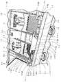
図1は、本発明を適用したスロットゲーム装置の外観斜視図、図2はスロットゲーム装置の要部斜視図である。
【0034】
本実施例のスロットゲーム装置は、プレーヤー(ゲーム実行者)がメダル1mをメダル投入器2a、2bからスタートチャッカー4(スタートチェック手段)のメダル通過口4tへ向けて投入し、メダル1mがメダル通過口4t(開口)に命中し通過することによりメカスロット6(実物体)が回転を開始する。
【0035】
そして、メカスロット6が自動的に回転を停止し、メカスロット6に表示される数字(マーク)が揃うこと(スロット当たり)によりメダル1mが払い出され(図7参照)、メダル1m(虚像の背面側から前面側へ移動する実物)が斜面を滑って虚像7の中から出現し落下して、ウィンゲート10、10(ゲート手段)間を通過したメダルがプレーヤーの獲得メダルとなるものである。
【0036】
スロットゲーム装置(以下、ゲーム装置と称す)1の前面には、プレーヤーが手で操作し易い位置に前方へ突出する水平な操作テーブル1tが形成されている。
【0037】
また、ゲーム装置1における前面側の上半部には、ゲーム装置1の内部を保護し、且つプレイヤーが内部を視認できるとともに虚像7を表示する透明なハーフミラー1gが後方へ傾斜する態様で設けられている。
【0038】
ここで、ゲーム装置1はレーン1Aとレーン1Bとの2つのレーンを備えており、各レーン1A、1Bにおいてそれぞれ最大2人のプレイヤーがゲームを行なうことができる。
【0039】
なお、本実施例ではレーンを2つ備えたゲーム装置1を例示しているが、レーンの数は適宜に設定し得るものである。
【0040】
ゲーム装置1のレーン1Aとレーン1Bとは全く同じ構造なので、以下ではレーン1Aについてのみ説明する。
【0041】
レーン1Aに相対してメダル投入器2aとメダル投入器2bが、操作テーブル1tの上方に設置されている。
【0042】
メダル投入器2aは、メダル投入口2ag1を有する投入器グリップ2agを具えており、投入器グリップ2agはプレイヤーが手で操作可能なように操作テーブル1t上方に露呈して設けられている。
【0043】
メダル投入器2aは、投入器グリップ2agに連続してメダル導出部2adが形成され、メダル導出部2adはハーフミラー1gにより保護される遊戯スペース内へ挿通し設置されている。
【0044】
なお、メダル投入器2bはメダル投入器2aと同じ構成である。
【0045】
そして、遊戯スペース内のメダル投入器2aのメダル導出部2adとメダル投入器2bのメダル導出部2bdとの下方部には、メダルテーブル3(テーブル部材)が奥方に向けて水平に設置されている。
【0046】
メダルテーブル3の奥側端縁部に近接して、所定数のメダル通過口4tを有するスタートチェッカー4が直立壁1w1に設けられている。
【0047】
スタートチェッカー4の上方には、前方に突出して形成される壁面に所定数のタイムランプ5が設置されている。
【0048】
タイムランプ5の奥側上方には、3桁の数字を表示するメカスロット6が配設され、メカスロット6は各桁の数字が表記されるドラム(後述)が各々独立して回転するように構成されている。
【0049】
なお、メカスロット6の内部には光源(図示せず)が収納されており、上記数字を内部から照射し、ゲーム装置1の前方に位置するプレイヤーにメカスロット6上の数字を際立たせて視認させる構成となっている。
【0050】
また、メカスロット6の周囲の壁面は暗く塗色されており、暗色部6o(虚像表示領域の背景と実物表示領域の暗色部)を形成している。
【0051】
そして、メカスロット6の上方は、ゲーム装置1の前方でプレイするプレイヤーによって視認される虚像7(後述)が配置されており、虚像7はメカスロット6と重畳して表示部を構成している。
【0052】
虚像7の上方にはメダル1mを払い出すメダル払出口8(後述、図5参照)を有するメダル供給装置(図示せず)が配設されている。
【0053】
メダル払出口8の下方には、前方に向けて傾斜する透明板9(連絡部)(後述、図5参照)がメカスロット6、タイムランプ5を上方から覆い配設されている。
【0054】
そして、透明板9およびハーフミラー1gの上方のゲーム装置1の上部カバー部1o(図1参照)内には虚像7の原映像を供給するモニター13(映像表示手段)が収納されている。(図5参照)
また、メダルテーブル3或いはメカスロット6の側方上方部にはゲームランプ19が配設されている。
【0055】
前記メダルテーブル3の前方下方域にはメダルテーブル3と隣接して、メダル滑走壁1w2が透明板9と同一平面を成すように前方下方へ向け傾斜し形成されており、メダル滑走壁1w2はゲーム装置1の前面内壁に続いている。
【0056】
そして、メダル滑走壁1w2上には一対のウィンゲート10、10(払い出しメダル制御手段)が回動自在に設置されている。
【0057】
また、ゲーム装置1の前面下部にはメダル排出口11が設置されており、このメダル排出口11は上記メダル滑走壁1w2からメダル1mを排出させる態様でメダル滑走壁1w2と連続して形成されている。
【0058】
さらに、ゲーム装置1の前面下部には上記メダル排出口11からメダル1mを受けとめるためのメダル排出口受け11uが取り付けられている。
【0059】
上述したレーン1Aとレーン1Bの間には、ゲームのポイント等を表示する表示装置12が設置されている。
【0060】
次に、上述したゲーム装置1の各部の構成について詳述する。
【0061】
メダル投入器2aは、投入器グリップ2agとメダル導出部2adとから構成されており、投入器軸材2ajの中心軸廻りに回動自在にゲーム機1に設置されている。
【0062】
なお、メダル投入器2aは、投入器グリップ2ag側が上方に位置し、メダル導出部2adの先端部側が下方に位置する態様で傾斜して設置されている。
【0063】
投入器グリップ2agはプレイヤーが投入するメダル1mの向きを手で操作するための部材であり、プレイヤーがマトを狙って手で左右方向へ回転操作可能なようにゲーム装置1の外部に露呈して回動自在に設けられている。
【0064】
投入器グリップ2agにはメダル1mを投入するためのメダル投入口2ag1が形成されており、プレイヤーがメダル投入口2ag1から一枚ずつメダル1mを投入する構成となっている。
【0065】
前述したように、メダル導出部2adは、一方側が投入器グリップ2agに固定され、他方側がハーフミラー1gによる遊戯スペース内に挿通し設置されている。
【0066】
メダル導出部2ad内には、メダル投入口2ag1から続いてメダル1mの案内路が形成されており、メダル投入口2ag1から投入されるメダル1mは、自重によりメダル導出部2a内を落下し案内され、ゲーム装置1内のメダルテーブル3上に投入される構成である。
【0067】
該メダル投入器2aの操作は、プレイヤーは、まず一方の手でメダル1mをメダル投入口2ag1の側壁へ押し付け、メダル1mがメダル投入器2a内に落下しないように保持しつつ、他方の手で投入器グリップ2agを左右方向へ回転操作することによりスタートチェッカー4のメダル通過口4tへメダル1mが転がり入るように狙う。
【0068】
そして、狙いを定めたら他方の手で投入器グリップ2agをその位置に固定しつつ、一方の手のメダル1mを押圧する力を緩めてメダル1mをメダル投入器2a内へ落下させてメダルテーブル3上に投入し、メダル1mをメダル通過口4tへ向けて転がす。
【0069】
プレイヤーは、ゲームに際してレーン1A又はレーン1Bの何れか一つを使用し、メダル投入器2a、2bを用いて上述した操作によりメダル1mをメダル通過口4tへ向けて投入するものである。
【0070】
上記メダルテーブル3は、図2、図3(a)に示すように、矩形状の平面を有する平板であり、メダル投入器2a、2b側の領域には傾斜モード(後述)時に払い出されたメダル1mが一気に落下することを防止するために、所定数のピン3pが垂直に立設されている。
【0071】
メダルテーブル3は、図3(b)に示すように、前端部を中心に揺動するように構成されており、図2のレーン1Aに示すように水平状態の水平モードと、図2のレーン1B、図3(b)の想像線で示すように、前端縁部を中心に透明板9の傾斜角度と略同一な角度に傾斜する傾斜状態である傾斜モードとを有している。
【0072】
メダルテーブル3が水平モード時は、プレイヤーがスタートチェッカー4のメダル通過口4tへ向けてメダル投入器2a、2bへメダル1mを投入することが可能であるモードである。
【0073】
ゲーム装置1がメダル1mを払い出すモードに移行した場合に、メダルテーブル3は傾斜モードに移行し、メダル払出口8から払い出されたメダル1mは透明板9上を滑走し、続いて傾斜したメダルテーブル3上を滑走し障害物であるピン3p、3p…をくぐり抜け、メダル滑走壁1w2上へ落下することになる。
【0074】
メダルテーブル3は、メダルの払い出しモード以外に適宜、傾斜モードに移行し、メダル通過口4を外れたメダル1m(図3(a)に示すD部に載置される)を、自重によりメダル滑走壁1w2上へ落下させるものである。
【0075】
上記スタートチェッカー4は、図3(c)に示すように、所定数のメダル通過口4tを有しており、両最側部のメダル通過口4tは中央側のメダル通過口4tより開口面積が大きく構成されている。
【0076】
該スタートチェッカー4は左右方向に往復運動を行っており、スタートチェッカー4の往復運動は、モーターの回転運動がカム、リンク等により変換されるものである。
【0077】
よって、スタートチェッカー4が最も右側に移動した場合は、プレイヤーに対し、αで示す最左端部の大きな開口のメダル通過口4tが露呈し、最も左側に移動した場合は、βで示す最右端部の大きな開口のメダル通過口4tが露呈する構成である。
【0078】
なお、本実施例では、スタートチェッカー4は一つの部材で構成しているが複数の部材の相対運動を用いることによりメダル通過口4tを構成することも可能である。
【0079】
また、スタートチェッカー4の運動は適宜、回転運動を採用してもよい。
【0080】
そして、スタートチェッカー4の後方には、メダル1mがメダル通過口4tを通過したことを検知するための光センサ22(通過検知手段、図11参照)が配設されている。
【0081】
光センサ22は、発光部 (発光ダイオード)と受光部 (フォトトランジスタ)とを具え、メダル通過口4tを通過したメダル1mが発光部から発した光を遮断し、受光部で光が検知されないことにより、メダル1mがメダル通過口4tを通過したことを検知している。
【0082】
上記タイムランプ5は所定数水平に設置されており、メダルテーブル3が傾斜モードへ移行すること、或いは、メカスロット6の回転中にプレイヤーの投入したメダル1mがスタートチェッカー4のメダル通過口4tを通過したこと等を、プレイヤーへ明示している。
【0083】
すなわち、タイムランプ5はゲーム開始に際して、全てのタイムランプ5が点灯しており、時間の経過と共に一つずつ消灯していきタイムランプ5が全て消えた段階においてメダルテーブル3は傾斜モードへ移行し、メダルテーブル3上に載置されるメダル1mを滑走壁1w2上へ落下させる。
【0084】
このように、タイムランプ5の点滅と、メダルテーブル3上のメダルをプレイヤーへ払い戻すテーブル3の傾斜モードおよびプレイヤーがメダル通過口4tへ向けてメダルを投入できる水平モードと、を連関させることにより、プレイヤーへゲーム装置1の一連の遊戯動作リズムを感得させ、軽快にゲームが行えるタイミングを認知させている。
【0085】
なお、上記の例ではタイムランプ5が全て消えた場合にメダルテーブル3は水平モードから傾斜モードへ移行することとしたが、逆に、開始時には全てのタイムランプ5が消灯しており、一つずつタイムランプ5を点灯していき、全てのタイムランプ5が点灯した段階においてメダルテーブル3を傾斜モードに移行させてもよい。
【0086】
或いは、所定数のタイムランプ5が消灯、或いは点灯した場合に、メダルテーブル3を水平モードから傾斜モードへ移行させる方法も適用可能であり、メダルテーブル3のモードに連関させるタイムランプ5の点灯、消灯方法はその他様々な方法が採用され得るものである。
【0087】
上記のメダルテーブル3のモードとの連関以外のタイムランプ5の明示機能としては、メカスロット6の回転中に、プレイヤーの投入したメダル1mがスタートチェッカー4のメダル通過口4tを通過した場合に、1つのタイムランプ5が点滅するものがある。
【0088】
上記一対のウィンゲート10、10は樹脂成形品であり、所定の厚みを有する三角形の平板状に成形されており、メダル滑走壁1w2上に互いに対称に配設されている。
【0089】
ウィンゲート10、10は、図3(a)、(d)、(e)に示すように、メダル滑走壁1w2上に軸10j廻りに揺動自在に設置されており、メダル滑走壁1w2上のウィンゲート10、10間(図3(d)、(e)のF部)(メダル返却通路)を滑走するメダル1mのみがメダル排出口11を介してメダル排出口受け11uへ貯留し、プレイヤーの獲得メダルになるように構成されている。
【0090】
なお、図3(d)、(e)のウィンゲート10、10間以外のG部(メダル非返却通路)を滑走するメダル1mはプレイヤーの獲得メダルにならず回収される。(図4参照)
ウィンゲート10、10は次の3つのモードを有している。
【0091】
すなわち、第1は、図3(d)、図4(a)に示すように、ウィンゲート10、10が矢印a方向に閉じており、滑走するメダル1mがウィンゲート10、10間を通過する確率が低いノーマル チューリップ モードである。
【0092】
第2は、ウィンゲート10、10が矢印b方向に開いており、図3(e)、図4(b)に示すように、滑走するメダル1mがウィンゲート10、10間を通過する確率が高いビッグ チューリップ モードである。
【0093】
第3は、図3(d)に示すように、ウィンゲート10、10が矢印a方向に閉じたり矢印b方向に開いたりの往復運動を行うレギュラー チューリップ モードであり、メダル1mがウィンゲート10、10間を通過する確率はノーマル チューリップ モードの確率以上、且つビッグ チューリップ モードの確率以下の値である。
【0094】
ウィンゲート10、10は通常、ノーマル チューリップ モードでゲームが進行され、チェックポイント(後述)通過後はレギュラー チューリップ モードに移行し、ジャックポット(Jack Pot)(後述)獲得後はビッグ チューリップ モードに移行する。
【0095】
なお、ウィンゲート10、10の開閉動作は、ゲームの進行に応じて開き具合を変化させる等、上記以外の様々な動作態様が適用可能である。
【0096】
ここで、図3に示すように、上記ウィンゲート10、10の構成と、往復運動を行うスタートチェッカー4の構成とが相俟って、プレイヤーの獲得メダルになるウィンゲート10、10間F部に対応して位置するメダル通過口4tは開口面積が狭小のため投入されたメダルが通過する可能性は低く、これに対し、プレイヤーの獲得メダルにならないウィンゲート10、10間G部に対応して位置するメダル通過口4tは開口面積が広大のため投入されたメダルが通過する可能性は高いものである。
【0097】
従って、プレイヤーが両側端部のメダル通過口4tを狙ってメダルを投入した場合、投入されたメダルがメダル通過口4tを通過する確率は高いが、もし、メダルがメダル通過口4tを通過できなかった時にはメダルは、メダルテーブル3が傾斜モードになった際にウィンゲート10、10間以外のG部を滑走することになり、プレイヤーが投入したメダルを再び回収することは不可能である。
【0098】
これに対し、中央部側のメダル通過口4tを狙ってメダルを投入した場合、投入されたメダルがメダル通過口4tを通過する確率は低いが、もし、メダルがメダル通過口4tを通過できなかった時にはメダルは、メダルテーブル3が傾斜モードになった際にウィンゲート10、10間のF部を滑走する可能性が高く、プレイヤーが投入したメダルを回収できる可能性が高くなっている。
【0099】
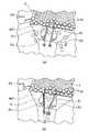
次に、上記メカスロット6と虚像7との構成を説明する。
【0100】
メカスロット6は、虚像・実物合成表示装置30を示す図5(a)から分かるように、円筒状の鋼板製のドラムであり、その周面に0〜9の数字が描かれた同じ大きさの円筒状のドラム6d1、6d2、6d3が厚さ方向に並設され構成されている。
【0101】
なお、メカスロット6の材質はプラスチック等、任意に選択可能である。
【0102】
各ドラム6d1、6d2、6d3は、メカスロット6の中心軸廻りに互いに独立して回転するように構成されており、ドラム6d1、6d2、6d3の間には暗色部6k(実物表示領域の暗色部)が配されている。
【0103】
そして、下方に向けて設置されているモニター13の映像は、45度の傾斜を有し配設されているハーフミラー1gにより90度屈折し、メカスロット6方向へ進み、垂直に虚像7として結像する。
【0104】
ここで、虚像7は、図5に示すように、透明板9とメカスロット6とに垂直に交錯している。
【0105】
虚像7は、図5(b)に示すように、上端部7h1から下方に向けて透明板9との交差部7h2までの虚像7aと、透明板9との交差部7h2から下方に向けてメカスロット6の周面との交差部7h3までの虚像7bと、メカスロット6の周面との交差部7h3から下方に向けてメカスロット6内で結像する下端部7h4までの虚像7cとを有している。
【0106】
図5(b)に示す表示部A(虚像表示領域)は、虚像7aが透明板9およびメカスロット6の周面より前方において結像しているので、ゲーム装置1の前方でプレイするプレイヤーには、虚像7aが最も前方に視認され、その後に透明板9が視認され、その後にメカスロット6の周面が位置しているように視認される。
【0107】
表示部B(虚像表示領域)は、前方から透明板9、虚像7b、メカスロット6の周面の順に位置しているので、ゲーム装置1の前方でプレイするプレイヤーには、透明板9が一番前方に視認され、その後に虚像7bが視認され、その後にメカスロット6の周面が位置しているように視認される。
【0108】
表示部C(実物表示領域)は、前方から透明板9、メカスロット6の周面、虚像7cの順に位置しているので、ゲーム装置1の前方でプレイするプレイヤーには、透明板9が一番前方に視認され、その後にメカスロット6の周面が視認され、メカスロット6内に虚像7cが位置しているように視認される。
【0109】
例えば、図6は、回転しているメカスロット6に虚像であるキャラクタ7c1とキャラクタ7c2とを重ねた表示した表示部を示している。
【0110】
キャラクタ7c1とキャラクタ7c2とは表示部Aと表示部Bとに映され、回転しているメカスロット6は表示部Bと表示部Cに配置されている。
【0111】
よって、ゲーム装置1の前方でプレイするプレイヤーには、表示部の表示部Aと表示部Bとでは虚像であるキャラクタ7c1とキャラクタ7c2とが一番前方に位置しているように視認され、その後に回転するメカスロット6の周面が位置しているように視認されることになる。
【0112】
例えば、図7は、表示部Aにキャラクタ7c1とキャラクタ7c4とが表示され、口を開いたライオンキャラクタ7c5が表示A部と表示B部とに表示されている。
【0113】
そして、メカスロット6がスロットが当たりとなり、メダル1mがメダル払出口8から払い出されている状態の表示部を示している。
【0114】
ここで、ライオンキャラクタ7c5の口が、図5(b)に示す虚像と透明板9との交錯部7h2である表示部Aと表示部Bとの境界(7h2)を含み位置しており、メダル払出口8から払い出されたメダル1mは透明板9上を滑走し、虚像7aの後方から交錯部7h2を境に虚像7bの前方に滑走している。
【0115】
そのため、ゲーム装置1の前方でプレイするプレイヤーには、表示部の上部にキャラクタ7c1とキャラクタ7c4とライオンキャラクタ7c5とが視認され、特に、ライオンキャラクタ7c5の口は表示B部と表示C部との境界(7h2)を含んで視認されるので、ライオンキャラクタ7c5の口からメダル1mが吐き出され、メカスロット6の周面の数字上(表示B部と表示C部)を滑走しているように視認される。
【0116】
図8(a)は、メカスロット6が回転を停止し、キャラクタ7c3(実物表示領域と虚像表示領域間を移動する虚像の映像、実物表示領域の暗色部に表示される虚像)が表示部Cのドラム6d1、6d2間に配置される暗色部6kに現れ、矢印aに示すように、表示部Cから表示部Bを経由し表示部Aに移動した状態を示している。
【0117】
ここで、図5(b)に示すように、表示部Cにおいては虚像7cはメカスロット6の内部に位置しており、表示部Bにおいては虚像7bはメカスロット6の周面と透明板9間であるメカスロット6の周面前方に位置し、表示部Aにおいては虚像7aはメカスロット6の周面および透明板9の前方に位置している。
【0118】
従って、キャラクタ7c3が表示部Cのドラム6d1、6d2間の暗色部6kに現れ、矢印aに示すように表示部Cから表示部Bを経由し表示部Aに移動した場合には、ゲーム装置1の前方でプレイするプレイヤーには、キャラクタ7c3はあたかもメカスロット6の内部より現れ、メカスロット6の前方に移動して行くように視認されることになる。
【0119】
図8(b)は、図8(a)に示す表示部において、さらに、表示部Aにキャラクタ7c4が現れ、「DEVIL HIT!」という文字が表示されている。
【0120】
そして、キャラクタ7c3が持っているかなづち7ckをメカスロット6に振り下ろしたと同時にメカスロット6のドラム6d1、6d2、6d3が回転を開始した状態を示している。
【0121】
このように、虚像であるキャラクタ7c3の持つかなづち7ckと実物であるメカスロット6の動作の同期をとることにより、あたかも、虚像であるキャラクタが実物に動作を及ぼしているようにプレイヤーに視認させることが可能である。
【0122】
例えば、停止しているメカスロット6の上方の表示部Aに虚像であるキャラクタを出現させ、キャラクタが手でメカスロット6を上方に引き上げるように表示することと同期してメカスロット6の回転を開始させることにより、あたかもキャラクタが手でメカスロット6を回転させたかのように、プレイヤーに視認させることができる。
【0123】
また、図9は、333や555のスロット当たりになった場合に、メカスロット6内の光源を制御しドラム6d3の数字表示を暗色に変化させるとともに、表示部Cのドラム6d3上に虚像であるキャラクタ7c7を表示させ、メカスロット6のドラム6d1、6d2を回転させている例を示している。
【0124】
本構成によれば、メカスロット6のドラム6d1と6d2とに表示される数字が揃うことによりプレイヤーがスロット当たりを獲得することができるので、スロット当たりの確率が高まる。
【0125】
ここで、図9ではメカスロット6内の光源を制御しメカスロット6のドラム6d1、6d2、6d3のうち一つのドラムの表示を暗色に変化させ、虚像を表示する例を示したが、いずれか2つのドラムの表示を暗色に変化させて、当該ドラム上の表示部Cに虚像を表示してもよい。
【0126】
この場合は、回転するメカスロット6が停止し、虚像により隠蔽されていない1つのドラムが表示する数字に順位、例えば、7、3、5、…の順位をもたせ、ドラムが表示する数字に応じてプレイヤーへゲームポイントを提供するものである。
【0127】
一方、上記表示装置12は、文字表示が可能である16セグメントの蛍光表示管を用いて製作された4桁の数字または文字を表示する表示装置であり、ゲームのポイント等を表示する。
【0128】
図2に示す上記ゲームランプ19は、プレイヤが投入したメダル1mがスタートチャッカー4のメダル通過口4tを通過し、メカスロット6が回転しスロット当たりになった場合には、下方のランプから順番に1つのゲームランプ19が点灯する。
【0129】
すなわち、図10(a)に示すように、矢印に従って1回のスロット当たりにより下のゲームランプ19から1個のゲームランプ19が点灯していく、そして、各々のゲームランプ19が点灯した場合にメダル供給装置のメダル払出口8から払い出されるメダル1mの枚数はそれぞれ図に示す通りである。
【0130】
或いは、ゲームランプ19は、図10(b)に示すように、図10(a)の構成のステップ6とステップ9の間に1ステップを加え、また、ステップ9とステップ12の間に2ステップを加えて構成することも可能である。
【0131】
このように、ステップの構成は適宜設定可能である。
【0132】
次に、本実施例の制御手段について説明する。
【0133】
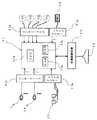
ゲーム装置1を制御するための制御手段20は、図11に示すように、コントロールの中心であるCPU(Centrl Processing Unit:中央処理装置)20aとデータを格納するためのRAM(Random Access Memory)20bとあらかじめ制御プログラムが焼き付けられたROM(Read Only Memory)20c等を具えている。
【0134】
ゲーム装置1の一連の動作は、ROM20c内に格納される制御プログラムを実行することにより行われるものであり、制御プログラムはアッセンブラ言語、或いはC言語等を用いて記述されている。
【0135】
制御手段20は、インターフェース21aを介して、メダルテーブル3を駆動するためのモータM1、スタートチェッカー4を駆動するためのモータM2、ウィンゲート10を駆動するためのモータM3、メカスロット6を駆動するためのモータM4に接続されており、インターフェース21aはモータ駆動回路である。
【0136】
また、制御手段20は、インターフェース21bを介して光センサ22に、インターフェース21cを介してタイムランプ5およびゲームランプ19にそれぞれ接続されており、インターフェース21bはセンサ回路、インターフェース21cはリレー駆動回路である。
【0137】
また、制御手段20は、表示装置12へ表示装置制御回路であるインターフェース21dを介して接続されている。
【0138】
さらに、制御手段20は、モニター13の映像内容を制御するための映像制御装置23(映像制御手段)に接続されている。
【0139】
映像制御装置23は、モニター13に表示する映像内容を記述した映像制御プログラムを格納したROM、データを格納するためのRAM等を有しており、映像制御プログラムを実行することによりモニター13に映像が表示される。
【0140】
モニター13に表示される映像の虚像と、制御手段20によって制御されるメカスロット6等の機構部材の動作との前述した連携は、映像制御プログラムと上記制御プログラム間において同期をとることにより行われる。
【0141】
次に、ゲーム装置1におけるゲームの概要を以下に記す。
【0142】
ゲーム装置1のゲームは12ステップを備え、構成されている。
【0143】
ゲームにおける12ステップは、図2に示すゲームランプ19によって示され、ステップの昇順はゲームランプ19の下からの位置の順番に対応している。
【0144】
すなわち、それぞれのステップとゲームランプ19との対応関係は図10(a)に示す通りであり、例えば、図2において最も下方のゲームランプ19は1ステップを示すゲームランプ、下から3番目のゲームランプ19は3ステップを示すゲームランプ、最も上のゲームランプ19は12ステップを示すゲームランプである。
【0145】
ここで、3ステップ、6ステップ、9ステップ、12ステップはチェックポイントのステップであり、払い出されるメダル1mの枚数が他のステップより多く設定されており、後のステップになるほど払い出されるメダル1mの枚数が多く設定されている。
【0146】
すなわち、3ステップでは払い出されるメダル1mの枚数は25枚、6ステップでは払い出されるメダル1mの枚数は50枚、9ステップでは払い出されるメダル1mの枚数は75枚、12ステップでは払い出されるメダル1mの枚数は125枚である。
【0147】
他のステップ、1、2、4、5、7、8、10、11ステップでは、払い出されるメダル1mの枚数は各10枚である。
【0148】
プレーヤーはゲームに際して、まず、スタートチャッカー4のメダル通過口4tを狙ってメダル投入器2aにメダル1mを投入する。
【0149】
投入したメダル1mがメダル通過口4tを通過することによりメカスロット6が回転を開始し、メカスロットが回転を自動的に停止しメカスロットに表示される数字が揃うこと、例えば、333、888、999等(スロット当たりの種類)になることによりスロット当たりになる。
【0150】
スロット当たりになった場合には、プレーヤーは次のステップへ進行し、そのステップに対応する枚数のメダル1mがメダル供給装置のメダル払出口8から払い出されるとともに、ゲームポイントを1ポイント獲得する。
【0151】
なお、ゲームポイントは表示装置12に表示され、スロット当たりにより1ポイントが加算されて表示される。
【0152】
そして、12ステップまで移行した場合には、再び1ステップから開始することになる。
【0153】
例えば、下から3番目までのゲームランプ19が点灯しており、スロット当たりになった場合には、下から4番目のゲームランプ19が点灯しステップ4に移行し、10枚のメダル1mが払い出され、ゲームポイントに1ポイントが加算される。
【0154】
或いは、下から5番目までのゲームランプ19が点灯しており、スロット当たりになった場合には、下から6番目のゲームランプ19が点灯しステップ6に移行し、50枚のメダル1mが払い出され、ゲームポイントに1ポイントが加算される。
【0155】
或いは、全てのゲームランプ19が消灯しており、スロット当たりになった場合には、下から1番目のゲームランプ19のみが点灯しステップ1に移行し、10枚のメダル1mが払い出され、ゲームポイントに1ポイントが加算される。
【0156】
ここで、スロット当たりのうち、777の数字が揃った場合はジャックポット当たりに設定されており、表示装置12に表示されているゲームポイントの数のメダル1mがメダル供給装置のメダル払出口8から払い出される。
【0157】
なお、ゲームポイントの初期値は、200、或いは300に初期設定されており、ジャックポット当たりの後は、再び初期値のゲームポイントから開始されるものである。
【0158】
なお、ゲームポイントの初期値は上記の値に拘らず任意に設定可能である。
【0159】
次に、ゲームの進行を図12を用いて説明する。
【0160】
(ステップ1)
プレイヤーは、図13(a)に示すように、メダル1mがスタートチェッカー4のメダル通過口4tへ入るようにメダル投入器2aを操作し、メダル1mをメダル投入器2aへ投入する。
【0161】
(ステップ2)
投入されたメダル1mがメダル通過口4tへ命中し、通過したか?
通過しない場合は、(ステップ1)に戻る。
【0162】
(ステップ3)
メダル1mが、図13(b)に示すように、メダル通過口4tを通過し、光センサ22により検知されると、メカスロット6のドラム6d1、6d2、6d3が各々独立に回転を開始する。
【0163】
(ステップ4)
メカスロット6のドラム6d1、6d2、6d3が自動的に回転を停止し、ドラム6d1、6d2、6d3に表記されている数字が揃うスロット当たりであるか?
スロット当たりでない場合は、(ステップ1)に戻る。
【0164】
(ステップ5)
メカスロット6のドラム6d1、6d2、6d3に表示される数字が『777』であるジャックポット(JACK POT)当たり?
(ステップ6)
ジャックポット当たりの場合には、メダルテーブル3が傾斜モード(図3(b)参照)へ移行するとともに、ウィンゲート10、10がビッグ チューリップ モード(図3(e)参照)に移行する。
【0165】
そして、表示装置12に表示されているゲームポイントの数のメダル1mがメダル供給装置のメダル払出口8から払い出される。
【0166】
払い出されたメダル1mは、透明板9上を滑走し、図13(c)に示すように、ライオンキャラクタ7c5の口からメダル1mが吐き出されるように落下し、さらにメダルテーブル3上を滑走し、次いで、メダル滑走壁1w2上を滑走する。
【0167】
そして、図4(b)に示すように、メダル滑走壁1w2上を滑走するメダル1mのうち、矢印に示すウィンゲート10、10間を通過するメダル1mがメダル排出口11を介してメダル排出口受け11uへ払い出され、プレイヤの獲得メダルになる。
【0168】
同時に、ゲーム機1は次のステップに移行し、そのステップのゲームランプ19が点灯し、表示装置12にはゲームポイントの初期値が表示される。
【0169】
(ステップ7)
スロット当たりにより移行する次のステップがチェックポイントのステップ(3、6、9、12ステップの何れか)であるか?
(ステップ8)
スロット当たりにより移行する次のステップがチェックポイントのステップの場合は、次のチェックポイントのステップに移行し、そのステップのゲームランプ19が点灯する。
【0170】
そして、メダルテーブル3が傾斜モード(図3(b)参照)へ移行するとともに、ウィンゲート10、10が、図3(d)に示すように、矢印a方向に閉じたり矢印b方向に開いたりの往復運動を行うレギュラー チューリップ モードに移行する。
【0171】
そして、移行したステップに対応する数のメダル1m(図10(a)参照)がメダル供給装置のメダル払出口8から払い出される。
【0172】
払い出されたメダル1mは、透明板9上を滑走し、図13(c)に示すように、ライオンキャラクタ7c5の口からメダル1mが吐き出されるように落下し、さらにメダルテーブル3上を滑走し、次いで、メダル滑走壁1w2上を滑走する。
【0173】
そして、図4に示すように、メダル滑走壁1w2上を滑走するメダル1mのうち、矢印に示すウィンゲート10、10間を通過するメダルがメダル排出口11を介してメダル排出口受け11uへ払い出され、プレイヤの獲得メダルになる。
【0174】
同時に、ゲームポイントに1ポイントが加算され、表示装置12に表示される。
【0175】
(ステップ9)
スロット当たりにより移行する次のステップがチェックポイントのステップでない場合は、次のステップに移行し、そのステップのゲームランプ19が点灯する。
【0176】
そして、メダルテーブル3が傾斜モード(図3(b)参照)へ移行し、ウィンゲート10、10は、図3(d)に示すように、ノーマル チューリップ モードの状態を維持する。
【0177】
そして、移行したステップに対応する数のメダル1m、すなわち、10枚のメダル1mがメダル供給装置のメダル払出口8から払い出される。
【0178】
払い出されたメダル1mは、透明板9上を滑走し、図13(c)に示すように、ライオンキャラクタ7c5の口からメダル1mが吐き出されるように落下し、さらにメダルテーブル3上を滑走し、次いで、メダル滑走壁1w2上を滑走する。
【0179】
そして、図4(a)に示すように、メダル滑走壁1w2上を滑走するメダル1mのうち、矢印に示すウィンゲート10、10間を通過するメダル1mがメダル排出口11を介してメダル排出口受け11uへ払い出され、プレイヤの獲得メダルになる。
【0180】
同時に、ゲームポイントに1ポイントが加算され、表示装置12に表示される。
【0181】
(ステップ10)
到達しているステップが最終ステップであるか?
(ステップ11)
到達しているステップが最終ステップである場合は、ゲームのステップを0ステップ(図10参照)に移行するとともに、全てのゲームランプ19が消灯する。
【0182】
そして、(ステップ1)に戻る。
【0183】
以上、ゲームの進行について述べてきたが、スロット当たりのパターンおよびスロット当たりの予告として下記のものが適宜採用される。
【0184】
虚像のみを用いるものとしては、当たりの予告として、虚像を用いてバック画面に変化をもたせたり、キャラクタにちょっとした動作をさせる。
【0185】
スロット当たりのパターンとしては、メカスロット6の動きに関係なく、スロット当たりを示唆するキャラクタ若しくは背景画面を表示し、例えば城から何かが出てくる、或いは、空が除々に暗くなる、雲が出てくる、雷が起きるというように、当たりが除々に近くなることを虚像を用いて表現することも可能である。
【0186】
メカスロット6のスロット当たりのパターンとしては、速い回転状態から急停止する、或いは、メカスロット6の回転速度を除々に低下させて当たりが近づくことをプレイヤに認識させる、或いは、メカスロット6のドラム6d1、6d2、6d3をそれぞれ1個戻させる等、適宜適用可能である。
【0187】
また、上記のスロット当たりの予告およびスロット当たりのパターンにおける虚像と、スロット当たりのパターンのメカスロット6の動作とを組み合わせることも可能である。
【0188】
また、ゲームランプ19に表示されるチェックポイントのステップの虚像の映像を、ステップ3を起、ステップ6を承、ステップ9を転、ステップ12を結としてストーリをもたせて展開することも適宜採用でき、チェックポイント毎に虚像の映像(背景、キャラクタ等)を変化させ、プレイヤーを飽きさせないゲーム構成を作成することも可能である。
【0189】
上述の如く、ゲーム装置1は何種類かのストーリー性を有した映像を表示することによりストーリーの進行に伴う期待感や達成感をプレイヤーに抱かせ、メカスロットのみの表示部を備えるゲーム装置では実現不可能な表示上の遊戯性を有している。
【0190】
なお、上記実施例では、『777』をジャックポットとして設定したが、他に『333』、『555』を他のスロット当たりより上位の当たりに設定し、ゲームポイントとしてスロットの機会を付与する等のイベントゲームをプレイヤーに提供してもよい。
【0191】
また、当たりの上位の順番、すなわち『777』が第1、『333』、『555』が第2、その他のスロットを第3の順番に、メカスロット6の表示の大きさや絵柄の大きさを強調してもよい。
【0192】
また、メカスロット6の表示は数字のみとしたが、絵柄が数字の形態をとってもよいし、或いは、数字を用いず絵柄を用いたり、或いは、絵柄と数字を結合して表現してもよい。
【0193】
なお、ウィンゲート10は、通過するメダル1mの量を制御できる構成であれば、上述の形態に拘らず構成可能であることは当然である。
【0194】
以上、本発明の虚像・実物合成表示装置によれば、メカスロットの暗色部の奥側であるメカスロットの内部に虚像であるキャラクタを登場させて、あたかもメカスロットの内部からキャラクタが現れたように演出することなど、実物が有する3次元性を利用して表示部の表現を豊かにすることが可能である。
【0195】
また、虚像であるキャラクタがメカスロットの回転を開始させたり、虚像であるキャラクタがメカスロットの回転を停止させたり等、虚像と実物を連携させて表現することにより、虚像と実物の結合を達成できる。
【0196】
また、虚像と払い出されるメダルとの交錯部に虚像であるキャラクタのライオンの口部を設定することにより、ライオンの口からメダルが払い出されるように表現できる等、虚像と実物とを連携させて表現することにより、迫力ある映像表現が可能である。
【0197】
また、メカスロットのドラムの何れか1つのドラムを暗転させ、虚像を表示し、2つのドラムを用いてスロットを行うことにより、よりスロット当たりの確率の高いスロットゲームが可能になる。
【0198】
或いは、メカスロットのドラムの何れか2つのドラムを暗転させ、虚像を表示し、1つのドラムを回転させてドラムが停止して表示される数字に予め順位付けを行い、表示される数字によりプレイヤーにゲームポイントを提供することにより、スロットゲームより有利なゲームを提供可能である。
【0199】
よって、表示部にメカスロットと虚像を適用することにより多彩なゲームが可能になる。
【0200】
さらに、虚像と実物であるメカスロットとを合成して表示するので、映像である虚像が有する空想性と実物のメカスロットが有する迫真性とが結合し、臨場感が豊溢するリーチパターンが可能となる。
【0201】
上述の如く、映像が有する空想性と実物が有する3次元性および迫真性とを結合して、映像と実物の融合を達成し得る虚像・実物合成表示装置が可能になる。
【0202】
一方、本発明のスロットゲーム装置によれば、メカスロットの暗色部の奥側であるメカスロットの内部に虚像であるキャラクタを登場させて、あたかもメカスロットの内部からキャラクタが現れたように演出することにより、表現豊かな表示部を有するスロットゲーム装置が得られる。
【0203】
また、虚像であるキャラクタがメカスロットの回転を開始させたり、虚像であるキャラクタがメカスロットの回転を停止させたり等、虚像と実物を連携させることにより虚像と実物とを結合した表現が可能である表示部を有するスロットゲーム装置が得られる。
【0204】
また、虚像と払い出されるメダルとの交錯部に虚像であるキャラクタのライオンの口部を設定することにより、ライオンの口からメダルが払い出されるように表現でき、迫力ある映像表現が可能であるスロットゲーム装置が得られる。
【0205】
また、メカスロットのドラムの何れか1つのドラムを虚像を用いて隠蔽し、2つのドラムを用いてスロットを行うことにより、よりスロット当たりの確率の高いスロットゲームが可能になる。
【0206】
或いは、メカスロットのドラムの何れか2つのドラムを虚像を用いて隠蔽し、1つのドラムを回転させてドラムが停止して表示される数字に予め順位付けを行い、表示される数字によりプレイヤーにゲームポイントを提供することにより、スロットゲームより有利なゲームが行える。
【0207】
よって、表示部にメカスロットと虚像を適用することにより多彩なゲームが可能なスロットゲーム装置が得られる。
【0208】
さらに、虚像と実物であるメカスロットとを合成して表示することにより、臨場感が豊溢するリーチパターンが可能であるスロットゲーム装置が得られる。
【0209】
従って、映像が有する空想性と実物が有する3次元性および迫真性とを結合して映像と実物の融合を達成し得る虚像・実物合成表示装置を具備するスロットゲーム装置が得られる。
【0210】
さらに、スロット当たりの種類に応じて、前記払い出されるメダルの量を増減することにより、ゲーム実行者はより上位のスロット当たりを期待してスロットゲーム装置を楽しむことができる。
【0211】
さらに、払い出されるメダルが通過する開閉自在なウィンゲートを具備し、通過したメダルをゲーム実行者の獲得メダルとし、ウィンゲートの開閉動作により前記メダルの通過量を調整することにより、多様性を有するメダルの払い出しを行えるスロットゲーム装置が得られる。
【0212】
そして、ゲームの進行状況に応じてウィンゲートの開き具合を変化させることにより、プレイヤーに視覚効果を促して射幸心をあおったり、ゲームへの興味をそそりゲームへの継続性を高めることが可能である。
【0213】
また、スロット当たりの種類に応じてウィンゲートの開閉動作を制御し、ゲーム実行者の獲得メダルを調整することにより、さらに多様性を有するメダルの払い出しを行えるスロットゲーム装置が得られる。
【0214】
また、メダルテーブルを上下方向に揺動させることにより、メダルテーブル上に載置されるメダルをプレイヤーへ回収させる傾斜モードと、プレイヤーがメダルをメダル通過口へ投入可能な水平モードとを構成し、タイムランプの点滅とメダルテーブルの水平・傾斜モードとを連関させることにより、プレイヤーへゲーム装置の一連の遊戯動作リズムを感得させ、軽快にゲームを行うことが可能である。
【0215】
また、メダル通過口を平行運動、或いは回転運動により移動させ、プレイヤーがメダルを通過させ易いメダル通過口は、該メダル通過口を通過させることができなかったメダルは、プレイヤーが回収することを困難に構成し、逆に、プレイヤーがメダルを通過させることが困難なメダル通過口は、該メダル通過口を通過させることができかったメダルはプレイヤーが回収がすることが容易に構成することで、よりギャンブル性の高いゲームが可能である。
【0216】
また、メカスロットによるスロット当たりを、速い回転状態から急停止する、或いは、回転速度を除々に低下させる、或いは、回転を戻させる、のうち少なくとも一つの方法を採用することにより、様々なメカスロットによるスロット当たりパターンを有するスロットゲーム装置が得られる。
【0217】
従って、虚像、実像合成表示装置を用いることにより豊かな映像表現が可能であると共に、娯楽性を向上させたスロットゲーム装置を実現できる。
【0218】
なお、上述した実施例においては、スロットゲーム装置へ本発明の虚像・実物合成表示装置を適用しているが、スロットゲーム装置以外の他のゲーム装置に本発明の虚像・実物合成表示装置を適用し得ることは言うまでもない。
【0219】
また、上述した実施例においては、一つの形態のスロットゲーム装置を例示したが、本発明のスロットゲーム装置を他の形態のゲーム装置に適用し得ることは言うまでもない。
【0220】
【発明の効果】
以上、詳述した如く、本発明に関わる虚像・実物合成表示装置は、虚像表示領域の背景、或いは、実物表示領域の少なくとも一部を暗色とすることにより、虚像を明瞭に表示できる。
【0221】
また、実物表示領域の少なくとも一部の暗色部に虚像を表示することにより、実物が有する3次元性を利用して虚像が実物内に存在するかのように表示でき、表示部の表現を豊かにすることが可能である。
【0222】
また、虚像に実物体の運動を連携させることにより、虚像と実物体の結合を達成できると共に、迫力ある映像表現が可能である。
【0223】
さらに、実物を虚像の背面側から前面側へ虚像を貫いて移動させ、虚像の前面側に移動することにより始めて視認可能とする、或いは、運動する実物と虚像とを合成して表示すること等により、臨場感が豊溢する表現が可能となる。
【0224】
従って、映像が有する空想性と実物が有する3次元性および迫真性とを結合した、映像と実物の融合を達成し得る虚像・実物合成表示装置が可能になる。
【0225】
本発明に関わるスロットゲーム装置は、メダルを虚像の後方から前方へ貫いて払い出し、虚像の前面側に移動して始めて視認可能とすることにより、迫力ある払い出しおよび映像表現が可能であるスロットゲーム装置が得られる。
【0226】
また、虚像に連携してメカスロットの運動を制御することにより虚像と実物とを結合した表現が可能であり、迫力ある映像表現が可能であるスロットゲーム装置が得られる。
【0227】
また、メカスロットの少なくとも1つのドラムを暗転させ、該ドラム上に虚像を表示することにより、2つのドラムをスロットを行ったり、1つのドラムを用いてゲームを行ったり等の多様性のあるメカスロットを用いるゲームが可能になる。
【0228】
また、複数のゲームランプによりゲームステップを表示し、ゲームランプの点灯に対応して虚像を変化させることにより、虚像により表現される表示にゲーム実行者へ期待感や達成感を抱かせ、また、飽きることのないゲーム構成を作成することが可能である。
【0229】
また、本発明に関わるスロットゲーム装置は、スロットの回転を開始するスタートチェック手段を設け、スタートチェック手段を通過する方法に多様性をもたせることで、よりギャンブル性の高いゲームが可能である。
【0230】
また、テーブル部材を支点中心に上下方向に揺動させることにより、テーブル部材上に倒置されるメダルをゲーム実行者へ回収させる傾斜状態と、ゲーム実行者がメダルをメダル通過口へ投入可能な水平状態とを構成し、タイムランプの点滅とテーブル部材の水平・傾斜状態とを連関させることにより、ゲーム実行者へゲーム装置の一連の遊戯動作リズムを感得させ、軽快にゲームを行わせることが可能である。
【0231】
また、払い出されるメダルが通過する量を制御するゲート手段とゲート開閉制御をと具備し、ゲートの進行状況に応じてメダルの通過量を調整することによって、多様性があるメダルの提供が可能であるスロットゲーム装置が得られる。
【0232】
さらに、スロット当たりの種類に応じて、ゲート手段を通過するメダルの量を制御することにより、ゲーム実行者がスロット当たりに大きく期待してゲームを行えるスロットゲーム装置が得られる。
【0233】
従って、虚像・実物合成表示装置を用いることにより豊かな映像表現が可能であると共に、娯楽性を向上させたスロットゲーム装置を達成できる。
【図面の簡単な説明】
【図1】本発明に関わるスロットゲーム装置の実施例を示す外観斜視図。
【図2】本発明に関わるスロットゲーム装置の実施例を示す要部斜視図。
【図3】 (a)、(b)、(c)、(d)、(e)は、本発明に関わるスロットゲーム装置の実施例を示すメダルテーブル、スタートチェッカーの近傍部を示す正面斜視図、メダルテーブルの動作を示す側面図、スタートチェッカーの動作を示す正面図、ウィンゲートの閉状態を示す正面図、ウィンゲートの開状態を示す正面図
【図4】 (a)および(b)は本発明に関わるスロットゲーム装置の実施例を示すウィンゲートの閉状態におけるメダルの滑走を示す斜視図、ウィンゲートの開状態におけるメダルの滑走を示す斜視図。
【図5】 (a)および(b)は本発明に関わる虚像・実物合成表示装置の実施例の原理を示す図および虚像と実物の位置関係を示す拡大側面図。
【図6】本発明に関わる虚像・実物合成表示装置の実施例における虚像とメカスロットを示す正面図。
【図7】本発明に関わる虚像・実物合成表示装置の実施例におけるメダルの払い出しを示す要部斜視図。
【図8】 (a)および(b)は本発明に関わる虚像・実物合成表示装置の実施例における虚像とメカスロットとの表示の推移を示す正面図。
【図9】本発明に関わる虚像・実物合成表示装置の実施例における虚像とメカスロットとの表示例を示す正面図。
【図10】 (a)および(b)は本発明に関わるスロットゲーム装置の実施例におけるゲームステップとゲームランプとの関係を示す図。
【図11】本発明に関わるスロットゲーム装置の実施例における制御手段の構成を示す図。
【図12】本発明に関わるスロットゲーム装置の実施例におけるゲームの流れを示す流れ図。
【図13】 (a)、(b)、(c)は、本発明に関わるスロットゲーム装置の実施例におけるゲームの推移を示す要部斜視図。
【符号の説明】
1…スロットゲーム装置、
1g…ハーフミラー、
1m…メダル、実物、
2a、2b…メダル投入器、
3…テーブル部材、
4…スタートチェッカー、スタートチェック手段、
4t…開口、
5…タイムランプ、
6…メカスロット、実物体、
6d1、6d2、6d3…ドラム、
6k…実物表示領域の暗色部、
6o…虚像表示領域の背景、実物表示領域の暗色部、
7c3…実物表示領域と虚像表示領域間を移動する虚像の映像、実物表示領域の暗色部に表示される虚像、
9…連絡部、
10…ゲート手段、
13…映像表示手段、
19…ゲームランプ、
20…制御手段、
22…通過検知手段、
23…映像制御手段、
30…虚像・実像合成表示装置、
A…虚像表示領域、
B…虚像表示領域、
C…実物表示領域、
F部…メダル返却通路、
G部…メダル非返却通路。[0001]
BACKGROUND OF THE INVENTION
The present invention relates to a slot game device.
[0002]
[Prior art]
Conventionally, as a game machine using a video display device using a virtual image, there is a target hitting game machine disclosed in JP-A-8-323037.
[0003]
The target hitting game machine displays a target image displayed on a CRT (Cathode-ray Tube) screen by combining a virtual image of a hitting table and a mirror image of a hammer of the player by the action of a half mirror.
[0004]
When playing the game, the player advances the game while looking at the screen of the video display device, and swings the hammer down so that the mirror image hammer hits the target video and hits the hitting table.
[0005]
When the target video is successfully hit, the impact sensor detects the hit operation and outputs a signal, and the video control device switches the target video on the CRT screen to the hit effect video based on the signal. is there.
[0006]
Alternatively, there are a composite image display device, a game device, and a bowling game device disclosed in JP-A-11-114221.
[0007]
The composite image display device combines an actual ball and a video ball and displays them to an observer, and includes a CRT display that displays a video and a mirror that forms a reflected virtual image of the video.
[0008]
In the game, the actual ball thrown by the player rolls on the moving surface, passes through the mirror, and moves to the back side.
[0009]
Then, when the actual ball passes through the half mirror portion of the mirror, a video ball having the same appearance shape as the actual ball appears, and the actual ball is replaced with the video ball.
[0010]
That is, after the actual ball is hidden behind the mirror, the video ball as a reflected virtual image continues to move.
[0011]
[Problems to be solved by the invention]
An object of the present invention is to enable a game with higher gambling characteristics in a slot game apparatus.
[0014]
[Means for Solving the Problems]
In order to achieve the above object, a slot game apparatus according to
[0015]
A slot game apparatus according to a second aspect of the present invention is the slot game apparatus according to the first aspect, wherein the slot game apparatus is arranged between the start check means and the medal inserter, and the inserted medal is rolled to the start check means. A table member arranged in a horizontal state for guiding and an inclined state for guiding the inverted medal to the medal return passage and the medal non-return passage is provided.
[0032]
DETAILED DESCRIPTION OF THE INVENTION
Hereinafter, the present invention will be described in detail with reference to the drawings illustrating embodiments.
[0033]
FIG. 1 is an external perspective view of a slot game apparatus to which the present invention is applied, and FIG. 2 is a perspective view of a main part of the slot game apparatus.
[0034]
In the slot game apparatus of this embodiment, a player (game executor) inserts a medal 1m from the
[0035]
Then, the
[0036]
On the front surface of the slot game device (hereinafter referred to as a game device) 1, a horizontal operation table 1t is formed that protrudes forward to a position where the player can easily operate it by hand.
[0037]
The upper half of the front side of the
[0038]
Here, the
[0039]
In the present embodiment, the
[0040]
Since the lane 1A and the lane 1B of the
[0041]
A
[0042]
The
[0043]
In the
[0044]
The
[0045]
A medal table 3 (table member) is horizontally installed in the lower part of the
[0046]
In the vicinity of the rear edge of the medal table 3, a
[0047]
Above the
[0048]
A
[0049]
A light source (not shown) is housed inside the
[0050]
The wall surface around the
[0051]
Above the
[0052]
Above the
[0053]
Below the
[0054]
A monitor 13 (image display means) for supplying the original image of the
Further, a
[0055]
In the lower front area of the medal table 3, the medal sliding wall 1w2 is formed to be inclined forward and downward so as to be flush with the
[0056]
A pair of
[0057]
In addition, a
[0058]
Further, a medal
[0059]
A
[0060]
Next, the configuration of each part of the above-described
[0061]
The
[0062]
The
[0063]
The thrower grip 2ag is a member for manually operating the direction of the medal 1m to be inserted by the player, and is exposed to the outside of the
[0064]
The inserter grip 2ag is formed with a medal insertion slot 2ag1 for inserting a medal 1m, and the player inserts the medal 1m one by one from the medal insertion slot 2ag1.
[0065]
As described above, the medal deriving portion 2ad is fixed to the thrower grip 2ag on one side and inserted into the play space by the half mirror 1g on the other side.
[0066]
In the medal deriving unit 2ad, a guide path for the medal 1m is formed following the medal insertion port 2ag1, and the medal 1m inserted from the medal insertion port 2ag1 is guided by dropping in the
[0067]
In the operation of the
[0068]
Then, when the aim is determined, while the thrower grip 2ag is fixed to the position with the other hand, the force that presses the medal 1m of one hand is loosened, and the medal 1m is dropped into the
[0069]
The player uses either one of the lane 1A or the lane 1B in the game, and inserts the medal 1m toward the
[0070]
As shown in FIGS. 2 and 3A, the medal table 3 is a flat plate having a rectangular plane, and the
[0071]
As shown in FIG. 3B, the medal table 3 is configured to swing around the front end portion. As shown in the lane 1A of FIG. 2, the medal table 3 is in the horizontal state in the horizontal state and the lane of FIG. 1B, as shown by the imaginary line in FIG. 3 (b), it has an inclination mode that is an inclined state in which the
[0072]
When the medal table 3 is in the horizontal mode, the player can insert the medal 1m into the
[0073]
When the
[0074]
The medal table 3 is shifted to the tilt mode as appropriate in addition to the medal payout mode, and the medal 1m (placed on the portion D shown in FIG. 3A) that has deviated from the
[0075]
As shown in FIG. 3C, the
[0076]
The
[0077]
Therefore, when the
[0078]
In this embodiment, the
[0079]
Further, the motion of the
[0080]
An optical sensor 22 (passage detection means, see FIG. 11) for detecting that the medal 1m has passed through the
[0081]
The
[0082]
A predetermined number of the
[0083]
That is, all the
[0084]
In this way, by associating the blinking of the
[0085]
In the above example, when all the
[0086]
Alternatively, a method of shifting the medal table 3 from the horizontal mode to the tilt mode when a predetermined number of
[0087]
As an explicit function of the
[0088]
The pair of
[0089]
As shown in FIGS. 3 (a), (d), and (e), the
[0090]
It should be noted that the medal 1m that slides in the G section (medal non-return passage) other than between the wingates 10 and 10 in FIGS. 3D and 3E is collected instead of being acquired by the player. (See Figure 4)
[0091]
That is, first, as shown in FIGS. 3D and 4A, the
[0092]
Secondly, the
[0093]
Third, as shown in FIG. 3 (d), the regular tulip mode in which the wingates 10 and 10 are reciprocated in the direction of the arrow a and closed in the direction of the arrow b and the medal 1m is the
[0094]
[0095]
Note that various operation modes other than the above can be applied to the opening and closing operations of the
[0096]
Here, as shown in FIG. 3, the configuration of the above-described
[0097]
Therefore, when a player inserts a medal aiming at the
[0098]
On the other hand, when a medal is inserted aiming at the medal passage opening 4t on the center side, the probability that the inserted medal passes through the
[0099]
Next, the structure of the
[0100]
As can be seen from FIG. 5 (a) showing the virtual image / actual
[0101]
The material of the
[0102]
Each of the drums 6d1, 6d2, 6d3 is configured to rotate independently of each other around the central axis of the
[0103]
The image of the
[0104]
Here, the
[0105]
As shown in FIG. 5B, the
[0106]
In the display section A (virtual image display area) shown in FIG. 5B, the virtual image 7a is formed in front of the peripheral surface of the
[0107]
Since the display part B (virtual image display area) is located in order of the
[0108]
Since the display unit C (actual display area) is located in the order of the
[0109]
For example, FIG. 6 shows a display unit in which a character 7c1 and a character 7c2 that are virtual images are superimposed on a rotating
[0110]
The character 7c1 and the character 7c2 are displayed on the display part A and the display part B, and the rotating
[0111]
Therefore, the player who plays in front of the
[0112]
For example, in FIG. 7, a character 7c1 and a character 7c4 are displayed on the display part A, and a lion character 7c5 with an open mouth is displayed on the display A part and the display B part.
[0113]
Then, the display portion in a state where the
[0114]
Here, the mouth of the lion character 7c5 is located including the boundary (7h2) between the display part A and the display part B, which is the intersection part 7h2 of the virtual image and the
[0115]
Therefore, a player playing in front of the
[0116]
In FIG. 8A, the
[0117]
Here, as shown in FIG. 5B, the virtual image 7 c is positioned inside the
[0118]
Accordingly, when the character 7c3 appears in the
[0119]
In FIG. 8B, in the display section shown in FIG. 8A, the character 7c4 appears on the display section A, and the characters “DEVIL HIT!” Are displayed.
[0120]
7 shows that the drum 6d1, 6d2, 6d3 of the
[0121]
As described above, by synchronizing the movement of the real 7th slot of the character 7c3 which is a virtual image and the
[0122]
For example, a character that is a virtual image appears on the display portion A above the stopped
[0123]
FIG. 9 shows a virtual image on the drum 6d3 of the display unit C while controlling the light source in the
[0124]
According to this configuration, the player can win per slot when the numbers displayed on the drums 6d1 and 6d2 of the
[0125]
Here, FIG. 9 shows an example in which the light source in the
[0126]
In this case, the rotating
[0127]
On the other hand, the
[0128]
In the
[0129]
That is, as shown in FIG. 10 (a), when one
[0130]
Alternatively, as shown in FIG. 10B, the
[0131]
Thus, the configuration of the steps can be set as appropriate.
[0132]
Next, the control means of the present embodiment will be described.
[0133]
As shown in FIG. 11, the control means 20 for controlling the
[0134]
A series of operations of the
[0135]
The control means 20 drives the motor M1 for driving the medal table 3, the motor M2 for driving the
[0136]
The control means 20 is connected to the
[0137]
The control means 20 is connected to the
[0138]
Further, the control means 20 is connected to a video control device 23 (video control means) for controlling the video content of the
[0139]
The video control device 23 includes a ROM that stores a video control program that describes video content to be displayed on the
[0140]
The above-described cooperation between the virtual image of the video displayed on the
[0141]
Next, the outline of the game in the
[0142]
The game of the
[0143]
Twelve steps in the game are indicated by the
[0144]
That is, the correspondence between each step and the
[0145]
Here,
[0146]
That is, the number of 1m medals to be paid out in 3 steps is 25, the number of 1m 1m to be paid out in 6 steps, the number of 1m medals to be paid out in 9 steps is 75, and the number of 1m medals to be paid out in 12 steps. Is 125 sheets.
[0147]
In other steps, 1, 2, 4, 5, 7, 8, 10, 11 steps, the number of medals 1m to be paid out is 10 each.
[0148]
In the game, the player first inserts a medal 1m into the
[0149]
When the inserted medal 1m passes through the
[0150]
In the case of winning per slot, the player proceeds to the next step, the number of medals 1m corresponding to that step are paid out from the
[0151]
The game points are displayed on the
[0152]
And when it transfers to 12 steps, it will start again from 1 step.
[0153]
For example, if the third to
[0154]
Alternatively, when the
[0155]
Alternatively, when all the
[0156]
Here, when 777 numbers are aligned per slot, it is set per jackpot, and the number of game points displayed on the
[0157]
Note that the initial value of the game point is initially set to 200 or 300, and after the jackpot, the game value starts again from the initial value of the game point.
[0158]
Note that the initial value of the game points can be arbitrarily set regardless of the above values.
[0159]
Next, the progress of the game will be described with reference to FIG.
[0160]
(Step 1)
As shown in FIG. 13 (a), the player operates the
[0161]
(Step 2)
Has the inserted medal 1m hit the
If not, return to (Step 1).
[0162]
(Step 3)
As shown in FIG. 13B, when the medal 1m passes through the
[0163]
(Step 4)
Is the drum 6d1, 6d2, 6d3 of the
If not per slot, return to (Step 1).
[0164]
(Step 5)
Is the jackpot (JACK POT) number “777” displayed on the drums 6d1, 6d2, 6d3 of the
(Step 6)
In the case of winning a jackpot, the medal table 3 shifts to the tilt mode (see FIG. 3B), and the wingates 10 and 10 shift to the big tulip mode (see FIG. 3E).
[0165]
Then, medals 1m corresponding to the number of game points displayed on the
[0166]
The paid-out medal 1m slides on the
[0167]
4B, among the medals 1m that slide on the medal sliding wall 1w2, the medals 1m that pass between the wingates 10 and 10 indicated by the arrows pass through the
[0168]
At the same time, the
[0169]
(Step 7)
Is the next step that moves more per slot the checkpoint step (any of 3, 6, 9, 12 steps)?
(Step 8)
If the next step that shifts per slot is the check point step, the next step is the check point step, and the
[0170]
Then, the medal table 3 is shifted to the tilt mode (see FIG. 3B), and the wingates 10 and 10 are closed in the direction of the arrow a or opened in the direction of the arrow b as shown in FIG. Move to regular tulip mode with reciprocating motion.
[0171]
Then, the number of medals 1m (see FIG. 10A) corresponding to the shifted step is paid out from the
[0172]
The paid-out medal 1m slides on the
[0173]
Then, as shown in FIG. 4, among the medals 1m sliding on the medal sliding wall 1w2, the medals passing between the wingates 10 and 10 indicated by the arrows are paid to the
[0174]
At the same time, 1 point is added to the game points and displayed on the
[0175]
(Step 9)
If the next step that shifts per slot is not a checkpoint step, the process proceeds to the next step, and the
[0176]
Then, the medal table 3 shifts to the tilt mode (see FIG. 3B), and the wingates 10 and 10 maintain the normal tulip mode state as shown in FIG. 3D.
[0177]
Then, the number of medals 1m corresponding to the shifted step, that is, ten medals 1m are paid out from the
[0178]
The paid-out medal 1m slides on the
[0179]
4A, among the medals 1m that slide on the medal sliding wall 1w2, the medals 1m that pass between the wingates 10 and 10 indicated by the arrows pass through the
[0180]
At the same time, 1 point is added to the game points and displayed on the
[0181]
(Step 10)
Is the step reached the final step?
(Step 11)
When the reached step is the final step, the game step shifts to 0 step (see FIG. 10) and all the
[0182]
Then, the process returns to (Step 1).
[0183]
As described above, the progress of the game has been described, but the following is appropriately adopted as a pattern per slot and a notice per slot.
[0184]
For those using only virtual images, as a preliminary announcement, the virtual screen is used to change the back screen or to make the character perform a little movement.
[0185]
As a pattern per slot, regardless of the movement of the
[0186]
As a pattern per slot of the
[0187]
It is also possible to combine the notice per slot and the virtual image in the pattern per slot with the operation of the
[0188]
In addition, it is possible to appropriately adopt the development of the virtual image of the check point step displayed on the
[0189]
As described above, the
[0190]
In the above embodiment, “777” is set as a jackpot, but “333” and “555” are set higher than other slots, and slot opportunities are given as game points. The event game may be provided to the player.
[0191]
Also, the top order of winning, that is, “777” is the first, “333”, “555” is the second, and the other slots are in the third order, and the display size and picture size of the
[0192]
In addition, the display of the
[0193]
Of course, the
[0194]
As described above, according to the virtual image / actual composite display device of the present invention, the character that is a virtual image appears inside the mechanical slot that is behind the dark color portion of the mechanical slot, and it appears as if the character appears from inside the mechanical slot. It is possible to enrich the expression of the display unit by utilizing the three-dimensional property of the real thing, such as producing the image.
[0195]
In addition, the virtual image and the real object can be connected by expressing the virtual image and the real object in cooperation, such as the character that is the virtual image starts rotating the mechanical slot and the character that is the virtual image stops rotating the mechanical slot. it can.
[0196]
In addition, by setting the mouth of the lion of the character that is a virtual image at the intersection of the virtual image and the medals to be paid out, it is possible to express the medals from the lion's mouth so that the virtual image and the real thing can be linked. By doing so, powerful video expression is possible.
[0197]
Further, a slot game with a higher probability per slot can be realized by darkening any one of the drums of the mechanical slot, displaying a virtual image, and performing a slot using two drums.
[0198]
Alternatively, any two of the drums in the mechanical slot are darkened, a virtual image is displayed, one drum is rotated, the drum is stopped and the numbers displayed are ranked in advance, and the player displays the numbers displayed. By providing game points, it is possible to provide a game more advantageous than the slot game.
[0199]
Therefore, various games are possible by applying a mechanical slot and a virtual image to the display unit.
[0200]
Furthermore, since the virtual image and the real mechanical slot are combined and displayed, the fantasy of the virtual image, which is the image, and the realism of the real mechanical slot are combined, enabling a reach pattern with a rich sense of reality. It becomes.
[0201]
As described above, a virtual image / actual composite display device that can achieve the fusion of the image and the real object by combining the fantasy of the image with the three-dimensionality and the authenticity of the real object becomes possible.
[0202]
On the other hand, according to the slot game apparatus of the present invention, a character that is a virtual image appears in the inside of the mechanical slot that is behind the dark portion of the mechanical slot, and the effect is as if the character appeared from inside the mechanical slot. As a result, a slot game apparatus having an expressive display unit can be obtained.
[0203]
In addition, it is possible to combine the virtual image and the real object by linking the virtual image and the real object, such as a character that is a virtual image starting the rotation of the mechanical slot and a character that is a virtual image stopping the rotation of the mechanical slot. A slot game apparatus having a display unit is obtained.
[0204]
In addition, by setting the mouth of the lion of the character that is a virtual image at the intersection of the virtual image and the medals to be paid out, it is possible to express the medals from the lion's mouth so that a powerful video expression is possible. A device is obtained.
[0205]
Further, by hiding any one of the drums of the mechanical slot using a virtual image and performing a slot using two drums, a slot game with a higher probability per slot becomes possible.
[0206]
Alternatively, any two of the drums in the mechanical slot are concealed using a virtual image, and one drum is rotated to stop the drums and prioritize the numbers displayed. By providing game points, a game more advantageous than the slot game can be performed.
[0207]
Therefore, a slot game device capable of various games can be obtained by applying a mechanical slot and a virtual image to the display unit.
[0208]
Furthermore, by combining and displaying a virtual image and a real mechanical slot, a slot game device capable of a reach pattern with a rich sense of reality can be obtained.
[0209]
Therefore, it is possible to obtain a slot game apparatus including a virtual image / real composite display device that can combine the fantasy of a video with the three-dimensionality and realness of the real to achieve fusion of the video and the real.
[0210]
Furthermore, by increasing or decreasing the amount of medals to be paid out according to the type per slot, the game player can enjoy the slot game device expecting a higher slot per slot.
[0211]
In addition, a wingate that can be freely opened and closed through which medals to be paid out pass is used, and the passing medal is used as a medal acquired by the game performer, and the passing amount of the medal is adjusted by opening and closing the wingate. A slot game device capable of paying out medals is obtained.
[0212]
And by changing the degree of opening of the Wingate according to the progress of the game, it is possible to encourage the player to have a visual effect and to increase continuity to the game. is there.
[0213]
Further, a slot game apparatus capable of paying out more diverse medals can be obtained by controlling the opening / closing operation of the wingate according to the type per slot and adjusting the medal earned by the game performer.
[0214]
In addition, a tilt mode in which the player collects medals placed on the medal table by swinging the medal table up and down, and a horizontal mode in which the player can insert medals into the medal passage opening, By associating the blinking of the time lamp with the horizontal / tilt mode of the medal table, it is possible to make the player feel a series of play rhythms of the game apparatus and play the game lightly.
[0215]
In addition, a medal passage port that allows a medal passage port to be moved by a parallel motion or a rotational motion so that a player can easily pass a medal is difficult for a player to collect a medal that could not pass the medal passage port. On the contrary, the medal passage port where it is difficult for the player to pass the medal is configured so that the player can easily collect the medal that could not pass the medal passage port, More gambling games are possible.
[0216]
In addition, various mechanical slots are adopted by adopting at least one method of suddenly stopping from a fast rotation state, gradually decreasing the rotation speed, or returning the rotation per slot by the mechanical slot. Thus, a slot game device having a pattern per slot is obtained.
[0217]
Therefore, by using the virtual image and real image composition display device, it is possible to realize a slot game device capable of expressing a rich image and improving entertainment.
[0218]
In the above-described embodiments, the virtual image / real composite display device of the present invention is applied to the slot game device, but the virtual image / real composite display device of the present invention is applied to other game devices other than the slot game device. It goes without saying that it can be done.
[0219]
In the above-described embodiment, one type of slot game device is illustrated, but it goes without saying that the slot game device of the present invention can be applied to other types of game devices.
[0220]
【The invention's effect】
As described above in detail, the virtual image / real composite display device according to the present invention can clearly display a virtual image by setting at least a part of the background of the virtual image display region or the real display region to a dark color.
[0221]
In addition, by displaying a virtual image in at least a part of the dark color area of the real display area, it is possible to display the virtual image as if it existed in the real object by utilizing the three-dimensional property of the real object, thereby enriching the display section. It is possible to
[0222]
In addition, by linking the movement of the real object to the virtual image, it is possible to achieve a connection between the virtual image and the real object and to achieve powerful video expression.
[0223]
Furthermore, moving the real object through the virtual image from the back side to the front side of the virtual image and moving it to the front side of the virtual image makes it possible to visually recognize it, or synthesizes and displays the moving real image and the virtual image, etc. Makes it possible to express with a rich sense of reality.
[0224]
Therefore, a virtual image / real composite display device that can combine the fantasy of the video with the three-dimensionality and the authenticity of the real and achieve the fusion of the video and the real is possible.
[0225]
The slot game apparatus according to the present invention is a slot game apparatus which allows powerful payout and video expression by allowing a medal to be paid out through the virtual image from the rear to the front and moving to the front side of the virtual image. Is obtained.
[0226]
Further, by controlling the motion of the mechanical slot in cooperation with the virtual image, it is possible to express the combined virtual image and the real thing, and to obtain a slot game device capable of powerful video expression.
[0227]
In addition, by darkening at least one drum of a mechanical slot and displaying a virtual image on the drum, a variety of mechanisms such as slotting two drums, playing a game using one drum, etc. A game using a slot becomes possible.
[0228]
In addition, by displaying a game step with a plurality of game lamps and changing the virtual image in response to the lighting of the game lamp, the display expressed by the virtual image gives the game performer a sense of expectation and achievement, It is possible to create a game configuration that does not get bored.
[0229]
In addition, the slot game apparatus according to the present invention is provided with start check means for starting the rotation of the slot, and a variety of methods for passing through the start check means enables a game with higher gambling.
[0230]
In addition, by swinging the table member up and down around the fulcrum, the game player can collect medals placed on the table member in a tilted state, and the game player can insert medals into the medal passage opening. The state of the game is linked to the blinking of the time lamp and the horizontal / tilted state of the table member. Is possible.
[0231]
It is also possible to provide a variety of medals by providing gate means for controlling the amount of medals to be paid out and gate opening / closing control, and adjusting the amount of medals passed according to the progress of the gate. A slot game device is obtained.
[0232]
Further, by controlling the amount of medals passing through the gate means according to the type per slot, a slot game device can be obtained in which the game player can play a game with great expectation per slot.
[0233]
Therefore, by using the virtual image / real composite display device, it is possible to achieve a slot game device capable of expressing a rich image and improving entertainment.
[Brief description of the drawings]
FIG. 1 is an external perspective view showing an embodiment of a slot game apparatus according to the present invention.
FIG. 2 is a perspective view of a main part showing an embodiment of a slot game apparatus according to the present invention.
3 (a), (b), (c), (d), and (e) are front perspective views showing the vicinity of a medal table and a start checker showing an embodiment of a slot game apparatus according to the present invention. , Side view showing the operation of the medal table, front view showing the operation of the start checker, front view showing the closed state of the wingate, front view showing the open state of the wingate
FIGS. 4A and 4B are perspective views showing sliding of medals in the closed state of the wingate showing an embodiment of the slot game apparatus according to the present invention, and perspective views showing sliding of the medals in the opened state of the wingate. Figure.
FIGS. 5A and 5B are diagrams showing the principle of the embodiment of the virtual image / real object combination display device according to the present invention and enlarged side views showing the positional relationship between the virtual image and the real object. FIGS.
FIG. 6 is a front view showing a virtual image and a mechanical slot in the embodiment of the virtual image / real composite display device according to the present invention.
FIG. 7 is a main part perspective view showing the payout of medals in the embodiment of the virtual image / real composite display device according to the present invention.
FIGS. 8A and 8B are front views showing transition of display of a virtual image and a mechanical slot in the embodiment of the virtual image / real composite display device according to the present invention. FIGS.
FIG. 9 is a front view showing a display example of a virtual image and a mechanical slot in the embodiment of the virtual image / real composite display device according to the present invention.
FIGS. 10A and 10B are diagrams showing a relationship between a game step and a game lamp in an embodiment of the slot game apparatus according to the present invention.
FIG. 11 is a view showing a configuration of control means in the embodiment of the slot game apparatus according to the present invention.
FIG. 12 is a flowchart showing a game flow in the embodiment of the slot game apparatus according to the present invention.
FIGS. 13A, 13B, and 13C are perspective views showing the main part of a game transition in an embodiment of the slot game apparatus according to the present invention.
[Explanation of symbols]
1 ... Slot game device,
1g ... half mirror,
1m ... medal, real thing,
2a, 2b ... medal inserter,
3 ... Table member,
4 ... Start checker, start check means,
4t ... opening,
5 ... Time lamp,
6 ... Mecha slot, real object,
6d1, 6d2, 6d3 ... drum,
6k ... dark part of the real display area,
6o: Background of the virtual image display area, dark portion of the real display area,
7c3: a virtual image moving between the real display area and the virtual image display area, a virtual image displayed in a dark color portion of the real display area,
9 ... Contact Department,
10 ... Gate means,
13 ... Video display means,
19 ... Game lamp,
20 ... control means,
22: Passing detection means,
23. Image control means,
30 ... Virtual image / real image composite display device,
A ... Virtual image display area,
B ... Virtual image display area,
C: Real display area,
Part F: Medal return passage,
Part G: Medal non-return passage.
Claims (2)
Translated fromJapaneseゲーム実行者によってメダルが投入されるメダル投入器と、
前記メダルが命中し通過する複数の開口を有し、前記投入されたメダルの前記開口への命中、非命中を決するスタートチェック手段と、
メカスロットの回転を開始させるために前記メダルの前記開口への通過により命中を検知する通過検知手段と、
通過できなかったメダルを、メダル排出口受けに案内するメダル返却通路と、回収すべく案内する非返却通路と
を具備し、
前記スタートチェック手段が有する複数の開口は、メダル非返却通路に近いほど開口が大きく、メダル返却通路に近いほど開口が小さい
ことを特徴とするスロットゲーム装置。A control means, a mechanical slot whose rotation and stop control are performed by the control means, and a medal supply device whose medal payout control is performed by the control means when the numbers displayed when the mechanical slot is stopped are aligned. A slot game device comprising:
A medal inserter in which medals are inserted by the game performer,
A plurality of openings through which the medal hits and passes, and a start check means for determining whether the inserted medal is hit to the opening or not hit;
Passage detecting means for detecting a hit by passing the medal to the opening to start rotation of the mechanical slot;
A medal return passage that guides medals that could not pass to the medal outlet and a non-return passage that guides them to collect them,
The slot game device characterized in that the plurality of openings of the start check means are larger as they are closer to the medal non-return passage and smaller as they are closer to the medal return passage.
ことを特徴とする請求項1に記載のスロットゲーム装置。Between the start check means and the medal inserter, and in a horizontal state where the inserted medal is guided to the start check means by rolling, and an inclined state where the inverted medal is guided to the medal return passage and the medal non-return passage The slot game apparatus according to claim 1, further comprising a coordinated table member.
Priority Applications (4)
| Application Number | Priority Date | Filing Date | Title |
|---|---|---|---|
| JP2000382828AJP3726881B2 (en) | 2000-12-15 | 2000-12-15 | Slot game device |
| TW090118593ATW528611B (en) | 2000-12-15 | 2001-07-31 | Unit for compositing and displaying virtual image and real entity, and slot game machine |
| US10/011,764US6638165B2 (en) | 2000-12-15 | 2001-12-11 | Virtual image/real image superimposing and displaying apparatus, and slot machine |
| KR10-2001-0079349AKR100514961B1 (en) | 2000-12-15 | 2001-12-14 | Virtual image/real image superimposing and displaying apparatus, and slot machine |
Applications Claiming Priority (1)
| Application Number | Priority Date | Filing Date | Title |
|---|---|---|---|
| JP2000382828AJP3726881B2 (en) | 2000-12-15 | 2000-12-15 | Slot game device |
Publications (2)
| Publication Number | Publication Date |
|---|---|
| JP2002182150A JP2002182150A (en) | 2002-06-26 |
| JP3726881B2true JP3726881B2 (en) | 2005-12-14 |
Family
ID=18850578
Family Applications (1)
| Application Number | Title | Priority Date | Filing Date |
|---|---|---|---|
| JP2000382828AExpired - Fee RelatedJP3726881B2 (en) | 2000-12-15 | 2000-12-15 | Slot game device |
Country Status (4)
| Country | Link |
|---|---|
| US (1) | US6638165B2 (en) |
| JP (1) | JP3726881B2 (en) |
| KR (1) | KR100514961B1 (en) |
| TW (1) | TW528611B (en) |
Families Citing this family (102)
| Publication number | Priority date | Publication date | Assignee | Title |
|---|---|---|---|---|
| AUPP518498A0 (en)* | 1998-08-10 | 1998-09-03 | Aristocrat Leisure Industries Pty Ltd | Gaming machine with transparent sprites |
| WO2002091319A2 (en)* | 2001-05-04 | 2002-11-14 | Igt | Light emitting interface displays for a gaming machine |
| US8342938B2 (en) | 2001-09-27 | 2013-01-01 | Igt | Gaming machine reel having a rotatable dynamic display |
| US8002624B2 (en)* | 2001-09-27 | 2011-08-23 | Igt | Gaming machine reel having a flexible dynamic display |
| US8083579B2 (en)* | 2001-10-02 | 2011-12-27 | Universal Entertainment Corporation | Slot machine and control method of game |
| US8025563B2 (en)* | 2001-10-02 | 2011-09-27 | Universal Entertainment Corporation | Gaming machine |
| JP2003111888A (en)* | 2001-10-02 | 2003-04-15 | Aruze Corp | Gaming server, gaming machine, and gaming management method |
| US8177623B2 (en)* | 2001-10-02 | 2012-05-15 | Aruze Gaming America, Inc. | Slot machine and control method of game |
| US8342936B2 (en)* | 2001-10-02 | 2013-01-01 | Universal Entertainment Corporation | Slot machine and control method of game |
| US7887410B2 (en)* | 2001-10-02 | 2011-02-15 | Universal Entertainment Corporation | Gaming machine |
| US8021225B2 (en)* | 2001-10-02 | 2011-09-20 | Universal Entertainment Corporation | Gaming machine |
| JP2003111889A (en)* | 2001-10-02 | 2003-04-15 | Aruze Corp | Gaming server, gaming machine, and gaming management method |
| JP2003111890A (en)* | 2001-10-05 | 2003-04-15 | Aruze Corp | Game server, game management method and game machine |
| US20080280666A1 (en)* | 2001-10-02 | 2008-11-13 | Aruze Corp. | Slot machine and control method of game |
| JP2003117053A (en)* | 2001-10-12 | 2003-04-22 | Aruze Corp | Game server, game management method and game machine |
| US20080318657A2 (en)* | 2001-10-02 | 2008-12-25 | Aruze Corporation | Gaming machine |
| US8033907B2 (en)* | 2001-10-02 | 2011-10-11 | Universal Entertainment Corporation | Slot machine and control method of game |
| JP2003111897A (en)* | 2001-10-09 | 2003-04-15 | Aruze Corp | Gaming server, gaming machine, gaming management server, and gaming management method |
| JP2003126343A (en)* | 2001-10-22 | 2003-05-07 | Aruze Corp | Gaming server, gaming machine, and gaming management method |
| JP3499855B2 (en)* | 2001-12-11 | 2004-02-23 | コナミ株式会社 | Display method |
| JP2003190367A (en) | 2001-12-21 | 2003-07-08 | Konami Co Ltd | False/real image superimposition display, image display control method and program for image display control |
| JP2003199868A (en)* | 2002-01-07 | 2003-07-15 | Konami Co Ltd | Cooperative performance display method |
| US7452276B2 (en)* | 2002-02-15 | 2008-11-18 | Wms Gaming Inc. | Simulation of mechanical reels on a gaming machine |
| AU2003253611A1 (en)* | 2002-05-23 | 2003-12-12 | Walker Digital, Llc | Apparatus having movable display |
| JP2004081475A (en)* | 2002-06-25 | 2004-03-18 | Aruze Corp | Gaming machine |
| US6939225B2 (en)* | 2002-06-27 | 2005-09-06 | Igt | Gaming device having bonus game with multiple moving objects within partitionable channels |
| JP2004081815A (en)* | 2002-06-28 | 2004-03-18 | Seiko Epson Corp | Display method, display device for gaming machine, and gaming machine |
| US20040018865A1 (en)* | 2002-07-24 | 2004-01-29 | Gilmore Jason C. | Gaming machine with interacting video and mechanical displays |
| US8454428B2 (en)* | 2002-09-12 | 2013-06-04 | Wms Gaming Inc. | Gaming machine performing real-time 3D rendering of gaming events |
| JP2004166820A (en) | 2002-11-18 | 2004-06-17 | Aruze Corp | Game machine |
| JP4081354B2 (en)* | 2002-11-18 | 2008-04-23 | アルゼ株式会社 | Game machine |
| US7404766B2 (en)* | 2002-11-19 | 2008-07-29 | Aruze Corp. | Gaming machine |
| US20040209666A1 (en)* | 2002-11-19 | 2004-10-21 | Hirohisa Tashiro | Gaming machine |
| US20050032571A1 (en)* | 2002-11-19 | 2005-02-10 | Masaaki Asonuma | Gaming machine |
| JP2004166959A (en) | 2002-11-20 | 2004-06-17 | Aruze Corp | Gaming machine |
| US7329181B2 (en)* | 2002-11-20 | 2008-02-12 | Aruze Corporation | Gaming machine with multilayered liquid crystal display for displaying images based on a priority order |
| JP2004166962A (en) | 2002-11-20 | 2004-06-17 | Aruze Corp | Game machine |
| US8096867B2 (en) | 2002-11-20 | 2012-01-17 | Universal Entertainment Corporation | Gaming machine and display device with fail-tolerant image displaying |
| US20050187003A1 (en)* | 2002-11-20 | 2005-08-25 | Takanobu Adachi | Gaming machine |
| US7972206B2 (en) | 2002-11-20 | 2011-07-05 | Wms Gaming Inc. | Gaming machine and display device therefor |
| JP2004166963A (en)* | 2002-11-20 | 2004-06-17 | Aruze Corp | Gaming machine |
| US7369102B2 (en)* | 2003-03-04 | 2008-05-06 | Microsoft Corporation | System and method for navigating a graphical user interface on a smaller display |
| JP2004267412A (en)* | 2003-03-07 | 2004-09-30 | Oizumi Corp | Game apparatus |
| JP3979963B2 (en)* | 2003-04-30 | 2007-09-19 | 株式会社コナミデジタルエンタテインメント | Game machine |
| US7892094B2 (en)* | 2003-05-14 | 2011-02-22 | Universal Entertainment Corporation | Gaming machine with a light guiding plate subjected to a light scattering process and having a light deflection pattern |
| US20040248642A1 (en)* | 2003-05-28 | 2004-12-09 | Rothschild Wayne H. | Adaptable gaming machine in a gaming network |
| US7341520B2 (en)* | 2003-06-25 | 2008-03-11 | Igt | Moving three-dimensional display for a gaming machine |
| US7775881B2 (en)* | 2003-09-15 | 2010-08-17 | Igt | Gaming apparatus having a configurable control panel |
| US7914378B2 (en)* | 2003-09-15 | 2011-03-29 | Igt | Gaming apparatus having a configurable control panel |
| JP2005124624A (en)* | 2003-10-21 | 2005-05-19 | Taito Corp | Token game machine with slope pin panel |
| JP2005137799A (en)* | 2003-11-10 | 2005-06-02 | Kpe Inc | Reel unit and game device |
| US7414595B1 (en)* | 2003-12-07 | 2008-08-19 | Advanced Simulation Displays Co. | Virtual mosaic wide field of view display system |
| US8016670B2 (en)* | 2004-01-12 | 2011-09-13 | Igt | Virtual glass for a gaming machine |
| US8545326B2 (en) | 2004-01-12 | 2013-10-01 | Igt | Casino display methods and devices |
| US8388432B2 (en) | 2004-01-12 | 2013-03-05 | Igt | Bi-stable downloadable reel strips |
| JP4054315B2 (en)* | 2004-02-06 | 2008-02-27 | 株式会社タイトー | Game machine |
| EP1571619A1 (en)* | 2004-03-01 | 2005-09-07 | Aruze Corporation | Gaming machine |
| AU2004200892B2 (en)* | 2004-03-01 | 2010-10-14 | Universal Entertainment Corporation | Gaming machine |
| EP1571611A1 (en)* | 2004-03-01 | 2005-09-07 | Aruze Corporation | Reel spinning slot machine with superimposed video image |
| AU2004200900B2 (en)* | 2004-03-01 | 2011-12-15 | Universal Entertainment Corporation | Gaming machine |
| US20060030387A1 (en)* | 2004-08-09 | 2006-02-09 | Jackson Kathleen N | Payline system for multiline slot play using an erasing/exposure feature |
| US7396279B2 (en)* | 2004-09-10 | 2008-07-08 | Igt | Gaming using terminating roaming wild positions |
| US7950994B2 (en) | 2004-09-10 | 2011-05-31 | Igt | Replacement reel gaming device and method |
| US20060058100A1 (en)* | 2004-09-14 | 2006-03-16 | Pacey Larry J | Wagering game with 3D rendering of a mechanical device |
| JP2006116204A (en)* | 2004-10-25 | 2006-05-11 | Aruze Corp | Game machine |
| US9071870B2 (en)* | 2004-12-08 | 2015-06-30 | Nokia Technologies Oy | System and method for viewing digital visual content on a device |
| US20070060249A1 (en)* | 2005-08-30 | 2007-03-15 | Gomez Benjamin T | Wagering game with superimposed images for highlighting gaming information |
| JP2007068905A (en)* | 2005-09-09 | 2007-03-22 | Aruze Corp | Game machine |
| KR100821528B1 (en)* | 2005-11-28 | 2008-04-11 | 주식회사 토비스 | Game machine with display screen |
| WO2007078752A2 (en) | 2005-12-19 | 2007-07-12 | Wms Gaming Inc. | Multigame gaming machine with transmissive display |
| JP4005101B2 (en)* | 2006-02-16 | 2007-11-07 | 株式会社コナミデジタルエンタテインメント | GAME SYSTEM, DETECTION PROGRAM, AND DETECTION METHOD |
| JP2007306986A (en)* | 2006-05-16 | 2007-11-29 | Dragon:Kk | Display type slot machine |
| JP2008017945A (en) | 2006-07-11 | 2008-01-31 | Aruze Corp | Game machine and game control method |
| US9117330B2 (en)* | 2006-08-01 | 2015-08-25 | Aristocrat Technologies Australia Pty Limited | Gaming system and a method of gaming |
| JP2008099893A (en)* | 2006-10-19 | 2008-05-01 | Aruze Corp | Slot machine and playing method of slot machine |
| US20080248859A1 (en)* | 2007-04-06 | 2008-10-09 | Gaming Enhancements, Inc. | Multiple game play in a stacked configuration |
| US9460582B2 (en)* | 2007-07-11 | 2016-10-04 | Bally Gaming, Inc. | Wagering game having display arrangement formed by an image conduit |
| JP2009039165A (en)* | 2007-08-06 | 2009-02-26 | Aruze Corp | Gaming machine |
| JP5122222B2 (en)* | 2007-09-12 | 2013-01-16 | 株式会社バンダイナムコゲームス | Game device |
| JP5031523B2 (en)* | 2007-11-08 | 2012-09-19 | 株式会社タイトー | Game device |
| US8172666B2 (en) | 2008-04-01 | 2012-05-08 | Aruze Gaming America, Inc. | Slot machine |
| US20090275386A1 (en)* | 2008-04-30 | 2009-11-05 | John Vallejo | Mechanical reels with interactive display and related methods |
| US8210935B2 (en)* | 2008-11-12 | 2012-07-03 | Igt | Gaming system, gaming device and method of providing collectors and tokens associated with collectors |
| US8152627B2 (en)* | 2009-01-15 | 2012-04-10 | King Show Games, Inc. | Gaming method and apparatus for facilitating a game involving specialty wild functionality |
| US8771056B2 (en)* | 2009-08-06 | 2014-07-08 | Bradley Berman | Systems, apparatuses and methods for awarding gaming payouts |
| JP5733783B2 (en)* | 2010-08-09 | 2015-06-10 | 株式会社バンダイナムコエンターテインメント | Medal game device |
| JP2013153872A (en)* | 2012-01-27 | 2013-08-15 | Universal Entertainment Corp | Gaming machine executing predictive performance |
| JP2013153873A (en)* | 2012-01-27 | 2013-08-15 | Universal Entertainment Corp | Gaming machine executing predictive performance |
| US9214067B2 (en) | 2012-09-06 | 2015-12-15 | Igt | Gaming system and method for providing a streaming symbols game |
| US8784174B2 (en) | 2012-09-25 | 2014-07-22 | Igt | Gaming system and method for providing an offer and acceptance game |
| US8840456B2 (en) | 2012-09-25 | 2014-09-23 | Igt | Gaming system and method for providing an offer and acceptance game |
| US9028318B2 (en) | 2012-09-27 | 2015-05-12 | Igt | Gaming system and method for providing a game which populates symbols along a path |
| US9039512B2 (en) | 2012-09-27 | 2015-05-26 | Igt | Gaming system and method for providing a game which populates symbols along a path |
| US8992301B2 (en) | 2012-09-27 | 2015-03-31 | Igt | Gaming system and method for providing a game which populates symbols along a path |
| US8784191B1 (en) | 2013-03-07 | 2014-07-22 | Igt | Gaming system and method for providing a symbol elimination game |
| US8851979B2 (en) | 2013-03-07 | 2014-10-07 | Igt | Gaming system and method for providing a symbol elimination game |
| KR101396860B1 (en)* | 2013-04-25 | 2014-05-20 | 주식회사 토비스 | Tree dimensional stereoscopic image device |
| US11145164B2 (en)* | 2013-07-23 | 2021-10-12 | Gemini Digital Development | Gaming machine having peripheral reels, a selectively transparent front display, and motor driven reels behind the front display |
| JP6396070B2 (en)* | 2014-04-25 | 2018-09-26 | 株式会社ソニー・インタラクティブエンタテインメント | Image fusion system, information processing apparatus, information terminal, and information processing method |
| US10147281B2 (en) | 2014-07-24 | 2018-12-04 | Igt | Gaming system and method having matching symbol stacks and additional award opportunities |
| US10186106B2 (en) | 2016-09-21 | 2019-01-22 | Igt | Gaming system and method for determining awards based on interacting symbols |
| USD1046911S1 (en)* | 2022-09-02 | 2024-10-15 | Aristocrat Technologies Australia Pty Limited | Display screen or portion thereof with transitional graphical user interface |
Family Cites Families (24)
| Publication number | Priority date | Publication date | Assignee | Title |
|---|---|---|---|---|
| US4797910A (en)* | 1986-05-07 | 1989-01-10 | American Telphone And Telegraph Company, At&T Bell Laboratories | Automated operator assistance calls with voice processing |
| US5267304A (en)* | 1991-04-05 | 1993-11-30 | At&T Bell Laboratories | Directory assistance system |
| US5120060A (en)* | 1991-09-05 | 1992-06-09 | James And Rosemarie Parker Family Trust | Casino game method and apparatus |
| JPH06343745A (en)* | 1993-06-03 | 1994-12-20 | Nifco Inc | Pachinko playing machine |
| JPH07136345A (en)* | 1993-11-15 | 1995-05-30 | Sanyo Electric Co Ltd | Boresight for game machine |
| JP3450454B2 (en)* | 1994-08-26 | 2003-09-22 | アルゼ株式会社 | Play equipment |
| JP3075336B2 (en)* | 1995-03-15 | 2000-08-14 | 株式会社ナムコ | Target hit game machine |
| JP3744590B2 (en) | 1995-03-31 | 2006-02-15 | 株式会社ナムコ | Target hitting game machine |
| US5917904A (en)* | 1995-05-12 | 1999-06-29 | Illinois Technology Transfer, Llc | Automatic area code detector and dialer |
| KR100201942B1 (en)* | 1996-12-16 | 1999-06-15 | 윤종용 | How to dial country code and area code. |
| US6061443A (en)* | 1997-05-28 | 2000-05-09 | Yablon; Gilbert J. | Unified method and apparatus to simplify telephone area code dialing |
| US6135884A (en)* | 1997-08-08 | 2000-10-24 | International Game Technology | Gaming machine having secondary display for providing video content |
| US6315666B1 (en)* | 1997-08-08 | 2001-11-13 | International Game Technology | Gaming machines having secondary display for providing video content |
| US6383076B1 (en)* | 1997-09-29 | 2002-05-07 | Iverson Gaming Systems, Inc. | Monitoring system for plural gaming machines using power line carrier communications |
| JP3758007B2 (en)* | 1997-10-17 | 2006-03-22 | 株式会社ナムコ | Composite image display device, game device, and bowling game device |
| JPH11151352A (en)* | 1997-11-20 | 1999-06-08 | Shimadzu Corp | Display for amusement machine |
| US6036189A (en)* | 1998-05-19 | 2000-03-14 | Williams Electronics Games, Inc. | Game with viewing panel having variable optical characteristics for producing virtual images |
| US6047962A (en)* | 1998-06-19 | 2000-04-11 | Williams Electronics Games, Inc. | Amusement game with pinball playfield and combined flipper/four-way switch |
| US6292557B1 (en)* | 1998-08-31 | 2001-09-18 | Lucent Technologies Inc. | Apparatus and method to insert the default local area code into a dialed telephone number |
| US6129353A (en)* | 1999-01-14 | 2000-10-10 | Williams Electronics Games, Inc. | Method of displaying video images projected from a video display of a pinball machine |
| US6338678B1 (en)* | 1999-08-23 | 2002-01-15 | Atlantic City Coin & Slot Service Company, Inc. | Ball selector and display device for use with gaming devices |
| US6464581B1 (en)* | 2000-09-01 | 2002-10-15 | Shuffle Master, Inc. | Video gaming symbols provided on a continuous virtual reel |
| US6517433B2 (en)* | 2001-05-22 | 2003-02-11 | Wms Gaming Inc. | Reel spinning slot machine with superimposed video image |
| US6517437B1 (en)* | 2001-08-31 | 2003-02-11 | Igt | Casino gaming apparatus with multiple display |
- 2000
- 2000-12-15JPJP2000382828Apatent/JP3726881B2/ennot_activeExpired - Fee Related
- 2001
- 2001-07-31TWTW090118593Apatent/TW528611B/ennot_activeIP Right Cessation
- 2001-12-11USUS10/011,764patent/US6638165B2/ennot_activeExpired - Lifetime
- 2001-12-14KRKR10-2001-0079349Apatent/KR100514961B1/ennot_activeExpired - Fee Related
Also Published As
| Publication number | Publication date |
|---|---|
| KR100514961B1 (en) | 2005-09-15 |
| KR20020047013A (en) | 2002-06-21 |
| TW528611B (en) | 2003-04-21 |
| US20020077172A1 (en) | 2002-06-20 |
| JP2002182150A (en) | 2002-06-26 |
| US6638165B2 (en) | 2003-10-28 |
Similar Documents
| Publication | Publication Date | Title |
|---|---|---|
| JP3726881B2 (en) | Slot game device | |
| JP2003199868A (en) | Cooperative performance display method | |
| JP4259782B2 (en) | Game machine | |
| JP2022144394A (en) | game machine | |
| JP4259783B2 (en) | Game machine | |
| JP4307577B2 (en) | Image-type game machine | |
| JP4265881B2 (en) | Game machine | |
| JP2022166555A (en) | game machine | |
| JP4650907B2 (en) | Game machine | |
| JP4997388B2 (en) | Slot machine | |
| JP4451035B2 (en) | Game machine | |
| JP2008161709A5 (en) | ||
| JP2019103705A (en) | Game machine | |
| JP2022166554A (en) | game machine | |
| JP2007000318A (en) | game machine | |
| JP2008119328A (en) | Game machine | |
| JP4671269B2 (en) | Bullet ball machine | |
| JP4307578B2 (en) | Image-type game machine | |
| JP7286698B2 (en) | game machine | |
| JP4553948B2 (en) | Game machine | |
| JPH119785A (en) | Image type game machine | |
| JP2004201965A (en) | Game machine and display screen control method | |
| JP4259784B2 (en) | Game machine | |
| JP4650908B2 (en) | Game machine | |
| JP2002219240A (en) | Gaming machine, game providing method, storage medium storing program capable of controlling the method, and server |
Legal Events
| Date | Code | Title | Description |
|---|---|---|---|
| A131 | Notification of reasons for refusal | Free format text:JAPANESE INTERMEDIATE CODE: A131 Effective date:20040203 | |
| A521 | Written amendment | Free format text:JAPANESE INTERMEDIATE CODE: A523 Effective date:20040401 | |
| A131 | Notification of reasons for refusal | Free format text:JAPANESE INTERMEDIATE CODE: A131 Effective date:20050524 | |
| A521 | Written amendment | Free format text:JAPANESE INTERMEDIATE CODE: A523 Effective date:20050721 | |
| TRDD | Decision of grant or rejection written | ||
| A01 | Written decision to grant a patent or to grant a registration (utility model) | Free format text:JAPANESE INTERMEDIATE CODE: A01 Effective date:20050823 | |
| A61 | First payment of annual fees (during grant procedure) | Free format text:JAPANESE INTERMEDIATE CODE: A61 Effective date:20050920 | |
| R150 | Certificate of patent or registration of utility model | Ref document number:3726881 Country of ref document:JP Free format text:JAPANESE INTERMEDIATE CODE: R150 Free format text:JAPANESE INTERMEDIATE CODE: R150 | |
| S111 | Request for change of ownership or part of ownership | Free format text:JAPANESE INTERMEDIATE CODE: R313111 | |
| R350 | Written notification of registration of transfer | Free format text:JAPANESE INTERMEDIATE CODE: R350 | |
| FPAY | Renewal fee payment (event date is renewal date of database) | Free format text:PAYMENT UNTIL: 20081007 Year of fee payment:3 | |
| S531 | Written request for registration of change of domicile | Free format text:JAPANESE INTERMEDIATE CODE: R313531 | |
| FPAY | Renewal fee payment (event date is renewal date of database) | Free format text:PAYMENT UNTIL: 20081007 Year of fee payment:3 | |
| R350 | Written notification of registration of transfer | Free format text:JAPANESE INTERMEDIATE CODE: R350 | |
| FPAY | Renewal fee payment (event date is renewal date of database) | Free format text:PAYMENT UNTIL: 20081007 Year of fee payment:3 | |
| FPAY | Renewal fee payment (event date is renewal date of database) | Free format text:PAYMENT UNTIL: 20091007 Year of fee payment:4 | |
| R250 | Receipt of annual fees | Free format text:JAPANESE INTERMEDIATE CODE: R250 | |
| FPAY | Renewal fee payment (event date is renewal date of database) | Free format text:PAYMENT UNTIL: 20101007 Year of fee payment:5 | |
| R250 | Receipt of annual fees | Free format text:JAPANESE INTERMEDIATE CODE: R250 | |
| FPAY | Renewal fee payment (event date is renewal date of database) | Free format text:PAYMENT UNTIL: 20101007 Year of fee payment:5 | |
| FPAY | Renewal fee payment (event date is renewal date of database) | Free format text:PAYMENT UNTIL: 20111007 Year of fee payment:6 | |
| R250 | Receipt of annual fees | Free format text:JAPANESE INTERMEDIATE CODE: R250 | |
| FPAY | Renewal fee payment (event date is renewal date of database) | Free format text:PAYMENT UNTIL: 20121007 Year of fee payment:7 | |
| R250 | Receipt of annual fees | Free format text:JAPANESE INTERMEDIATE CODE: R250 | |
| FPAY | Renewal fee payment (event date is renewal date of database) | Free format text:PAYMENT UNTIL: 20131007 Year of fee payment:8 | |
| R250 | Receipt of annual fees | Free format text:JAPANESE INTERMEDIATE CODE: R250 | |
| R250 | Receipt of annual fees | Free format text:JAPANESE INTERMEDIATE CODE: R250 | |
| R250 | Receipt of annual fees | Free format text:JAPANESE INTERMEDIATE CODE: R250 | |
| R250 | Receipt of annual fees | Free format text:JAPANESE INTERMEDIATE CODE: R250 | |
| R250 | Receipt of annual fees | Free format text:JAPANESE INTERMEDIATE CODE: R250 | |
| R250 | Receipt of annual fees | Free format text:JAPANESE INTERMEDIATE CODE: R250 | |
| R250 | Receipt of annual fees | Free format text:JAPANESE INTERMEDIATE CODE: R250 | |
| R250 | Receipt of annual fees | Free format text:JAPANESE INTERMEDIATE CODE: R250 | |
| LAPS | Cancellation because of no payment of annual fees |