JP3725174B2 - Devices for affecting the vehicle handling characteristics of remotely operated model vehicles - Google Patents
Devices for affecting the vehicle handling characteristics of remotely operated model vehiclesDownload PDFInfo
- Publication number
- JP3725174B2 JP3725174B2JP51616098AJP51616098AJP3725174B2JP 3725174 B2JP3725174 B2JP 3725174B2JP 51616098 AJP51616098 AJP 51616098AJP 51616098 AJP51616098 AJP 51616098AJP 3725174 B2JP3725174 B2JP 3725174B2
- Authority
- JP
- Japan
- Prior art keywords
- signal
- vehicle
- variable
- steering
- acceleration
- Prior art date
- Legal status (The legal status is an assumption and is not a legal conclusion. Google has not performed a legal analysis and makes no representation as to the accuracy of the status listed.)
- Expired - Fee Related
Links
- 230000001133accelerationEffects0.000claimsabstractdescription24
- 230000002596correlated effectEffects0.000claimsabstractdescription4
- FGRBYDKOBBBPOI-UHFFFAOYSA-N10,10-dioxo-2-[4-(N-phenylanilino)phenyl]thioxanthen-9-oneChemical compoundO=C1c2ccccc2S(=O)(=O)c2ccc(cc12)-c1ccc(cc1)N(c1ccccc1)c1ccccc1FGRBYDKOBBBPOI-UHFFFAOYSA-N0.000claims1
- 230000000875corresponding effectEffects0.000description3
- 238000010586diagramMethods0.000description3
- 238000009966trimmingMethods0.000description2
- 238000002485combustion reactionMethods0.000description1
- 230000001276controlling effectEffects0.000description1
- 238000011161developmentMethods0.000description1
- 230000018109developmental processEffects0.000description1
- 238000011156evaluationMethods0.000description1
- 238000000034methodMethods0.000description1
Images


Classifications
- A—HUMAN NECESSITIES
- A63—SPORTS; GAMES; AMUSEMENTS
- A63H—TOYS, e.g. TOPS, DOLLS, HOOPS OR BUILDING BLOCKS
- A63H30/00—Remote-control arrangements specially adapted for toys, e.g. for toy vehicles
- A63H30/02—Electrical arrangements
- A63H30/04—Electrical arrangements using wireless transmission
Landscapes
- Engineering & Computer Science (AREA)
- Computer Networks & Wireless Communication (AREA)
- Toys (AREA)
- Steering Control In Accordance With Driving Conditions (AREA)
- Selective Calling Equipment (AREA)
- Control Of Position, Course, Altitude, Or Attitude Of Moving Bodies (AREA)
- Motorcycle And Bicycle Frame (AREA)
Abstract
Description
Translated fromJapanese説明
本発明は、遠隔操作模型車両の車両操縦特性に作用するためのデバイスに関する。
現在の模型車両、すなわち模型自動車または模型船において、車両を操作する人が過度の速度で車両をカーブに導いてしまうという問題に頻繁に出くわしている。この結果として、車両が不安定な走行状態に陥り、すなわちその車両はそのカーブの外へ滑るように進むか、またはそれ始める(オーバーステアリングまたはアンダステアリング)。
上記に鑑み、本発明はこれを防ぐ目的に基づいている。
この目的を果たすため、本発明によれば、車両を操作する人に特定され得る第1コマンド変数を表す第1制御信号のための第1入力端子と、模型車両の回転速度または横方向の加速度と相関される外乱変数を表す第2制御信号を出力するセンサ手段と、第1制御信号を受けるための第1入力端子と接続され、かつ第2制御信号を受けるための第2入力端子を有し、第1コマンド変数及び外乱変数の関数である第1操作量を表す第1出力信号を生成する処理手段を含み、処理手段により生成される第1操作量が、外乱変数の関数として予め決められ得る度合に制限または変更されるコマンド変数である、デバイスが提供される。
このデバイスは、車両を操作する人により過度の舵取り角または過度の速度に特定されたにも係わらず、車両がそれるのを効率良く防ぐことを可能にする。
車両を操作する人により特定され得る第1コマンド変数は、好ましくは操舵装置駆動信号であり、処理手段により生成される第1操作量は、制限された及び/または反転された操舵装置駆動信号である。しかしながら、車両を操作する人によって特定され得る第1コマンド変数が、加速度または速度信号であり、また処理手段により生成される第1操作量が制限された加速度または速度信号であることも可能である。
さらに、車両を操作している人により特定され得るさらなるコマンド変数を表すさらなる制御信号のために、第3入力端子が提供されることもでき、そして処理手段により生成される第1出力信号は、第1及びさらなるコマンド変数、並びに外乱変数の関数である第1操作量を表す。
この目的のために、デバイスは、車両を操作している人により特定され得るさらなるコマンド変数を表すさらなる制御信号のための第3入力端子を含む。さらに、処理手段は、第1及び/またはそのさらなるコマンド変数、並びに外乱変数の関数であるさらなる操作量を表す第2出力信号を生成する。
操舵装置駆動信号の制御及び/または反転の上に、加速度または速度信号の制限も、その際処理手段によって行われることも好ましい。
さらに、その加速度または速度信号の制限の度合は、操舵装置駆動信号の制限及び/または反転の関数として処理手段により作用される。
本発明の好ましい態様においては、調整手段が、処理手段により提供される加速度または速度信号の制限の度合と率、及び/または操舵装置駆動信号の制限及び/または反転により提供される。
その処理手段は、車両が角を曲がる間にセンサ信号の関数として予め決められた度合に操舵装置駆動信号を変化し、制限し、または反転するように適合されている。
本発明によるデバイスのある態様では、第1センサ手段がジャイロスコープ、好ましくは圧電気振動ジャイロスコープにより形成される。
選択的に、第1センサ手段は、車両内に互いに離れて配置されている2つの加速度センサによって形成されることも可能である。
従来の遠隔操作ユニットと調和させるため、処理手段は、予め決められた形態の信号を処理及び/または出力するように適合されている。特に、第1制御信号、操舵装置駆動信号、及び/または加速度または速度信号のそれぞれが、好ましくは0.5から2.6msecの継続時間を有するパルス−タイプ信号である。
本発明による上記デバイスは、好ましくは構造的に、遠隔操作受信機、模型車両サーボ駆動、及び/または模型車両巡航操作(速度制御)にある。
デバイスは、模型車両に対して説明されるが、本発明は同じものに限定されない。本発明によるデバイスは、乗用車またはトラックにも使用できる。
本発明によるデバイスのさらに有利な態様、発展、性質、及び特徴は、以下の構成の説明から明らかになるであろう。
図1は、模型車両における本発明によるデバイスの略ブロック図を示している。
図2は、本発明によるデバイスの略ブロック図を詳細に示している。
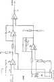
図3は、本発明による一態様の回路図を示している。
図1において、本発明によるデバイス10は、車両を操作する人により特定され得る操舵入力信号の形で第1コマンド変数waを表す第1制御信号14のための第1入力端子12を有する評価回路として示されている。
ジャイロセンサまたは2つの加速度センサは、模型車両の回転速度または横方向の加速度と相関されている外乱変数zを表す第2制御信号18を出力するセンサ手段16を形成している。
さらに、本発明によるデバイスは、さらに以下において、より詳細に説明され、第1制御信号14を受けるための第1入力端子14と接続され、かつ第2制御信号18を受けるための第2入力端子20を含む処理手段を有する。
この処理手段は、第1コマンド変数wa及び外乱変数zの関数である第1操作量y1を表す第1出力信号22を生成し、処理手段により生成されるその第1操作量y1は、外乱変数zの関数として予め決められ得る度合に制限または変更されたコマンド変数wである。
図1に示される態様では、車両を操作する人により特定され得る第1コマンド変数wは、操舵装置駆動信号Lであり、また処理手段により生成される第1操作量yは、制限された及び/または反転された操舵装置駆動信号L′である。この操舵装置駆動信号L′は、ドライバーステージ24内で増幅され、操舵装置のサーボモータ26に供給される。
図2は、第2態様の本発明によるデバイスを説明している。ここでは操舵に加え、さらなる信号「加速度信号」Gが処理される。この目的のために、車両を操作している人により特定され得るさらなるコマンド変数wbを表すさらなる制御信号Gのための第3入力端子30が備えられている。この制御信号Gは、速度特定信号である。
さらに、処理手段により生成される第1出力信号は、第1及び第2コマンド変数wa、wb、並びに外乱変数zの関数である第1操作量y1を表すように作用される。言いかえれば、サーボモータによる操舵装置に供給される操舵信号L′は、第1センサ16により影響されるだけでなく、車両を操作している人により特定される速度特定信号Gによっても影響される。
図2に示される態様においては、第2出力信号G′は、処理手段により生成され、これは第1及び他のコマンド変数wa、wb、並びに外乱変数zの関数であるさらなる操作量y2を表す。このことは、操舵装置のサーボモータに供給される信号に加え、舵取り角特定及び速度特定、並びにセンサ手段16からの信号の関数として処理手段により生成される、駆動モータの速度に対するさらなる制御信号(例えば、燃焼エンジンの場合ではエンジンスロットル位置)が提供されることを意味している。
処理手段は、操舵装置駆動信号の制限及び/または反転の上に、加速度または速度信号G′の制限も行われるように出力信号のそれぞれを形成するように適合されている。
この目的のために、処理手段は、加速度または速度信号G′の制限の度合と率を確立するための調整手段42、44、並びに処理手段による操舵装置駆動信号の制限及び反転の度合と率を確立するための調整手段46、48を含んでいる。
図示されている態様においては、調整手段はトリミングポテンショメータにより説明されている。これは、本発明によるデバイス及び処理手段がアナログ回路である場合に、特に当てはまる(以下の図3の説明も参照のこと)。しかしながら、マイクロコントローラによって本発明を実行することもできる。この場合、調整手段は、そのスイッチ位置がマイクロコントローラによって検知され、操作プログラムの実行中に考慮される8DIPスイッチ(eightfold DIP switches)によりそれぞれ実行され得る。
アナログ回路またはマイクロコントローラの何れが使用されるにせよ、処理手段は、センサ信号の関数として、車両が角を曲がる間に予め決められた度合に操舵装置駆動信号L及び/または速度特定信号を変化し、制限し、または反転し、またそれぞれ、好ましくは0.5から2.6msecの継続時間で、対応するパルス−タイプ信号G′またはL′として同じものを出力する。
図3は、本発明の本質的な特徴を具体化している単純なアナログ回路を示している。ジャイロセンサ16によって生成される2.3V±1.0Vの基準電圧が、比較器として接続されている第1演算増幅器OP1により入力信号14と比較される。比較器の出力信号は、積分器として接続されている演算増幅器OP2の反転入力に供給され、一方ジャイロセンサからの信号は、前記積分器の非反転入力に供給される。積分器の出力信号は、比較器として作動する演算増幅器OP3の非反転入力に供給され、一方ジャイロセンサにより生成される50Hzの帯域幅を持つパルス信号は、演算増幅器OP4内で増幅されて演算増幅器OP3の反転入力に供給される。演算増幅器OP3の出力信号は、図1の最終段に供給される。演算増幅器OP4は、そのフィードバックブランチ内にトリミングポテンショメータK1を有し、これにより利得が調整できる。
ジャイロセンサは、車両の回転に対応する信号(1.11mV/DEG/sec)を出力する。車両の回転速度に対応するこの変数は、反対操舵(countersteering)が行われることになる範囲を決定するために利用される。角を曲がる際、舵取り角はトリマー位置K1の関数として変形される。
舵取りサーボ位置は、舵取り入力信号及び/または加速度/ブレーキ信号に加え、他の因子に依存して作られることもできる。DESCRIPTION The present invention relates to a device for affecting the vehicle handling characteristics of a remotely operated model vehicle.
In current model vehicles, i.e. model cars or model ships, people frequently encounter the problem that a person operating the vehicle leads the vehicle to a curve at an excessive speed. As a result of this, the vehicle falls into an unstable driving state, i.e. the vehicle moves or begins to slide out of the curve (oversteering or understeering).
In view of the above, the present invention is based on the object of preventing this.
To this end, according to the present invention, a first input terminal for a first control signal representing a first command variable that can be specified by a person operating the vehicle, and a rotational speed or lateral acceleration of the model vehicle. Sensor means for outputting a second control signal representing a disturbance variable correlated with the first input terminal for receiving the first control signal and having a second input terminal for receiving the second control signal. And processing means for generating a first output signal representing a first manipulated variable that is a function of the first command variable and the disturbance variable, and the first manipulated variable generated by the processing means is predetermined as a function of the disturbance variable. A device is provided that is a command variable that is limited or modified to a degree that can be done.
This device makes it possible to efficiently prevent the vehicle from deviating despite being specified by the person operating the vehicle as having an excessive steering angle or excessive speed.
The first command variable that can be specified by the person operating the vehicle is preferably a steering device drive signal, and the first amount of operation generated by the processing means is a limited and / or inverted steering device drive signal. is there. However, the first command variable that can be specified by the person who operates the vehicle is an acceleration or speed signal, and the first operation amount generated by the processing means can be an acceleration or speed signal with a limited value. .
Furthermore, a third input terminal can be provided for further control signals representing further command variables that can be specified by the person operating the vehicle, and the first output signal generated by the processing means is: A first manipulated variable that is a function of the first and further command variables and the disturbance variable is represented.
For this purpose, the device includes a third input terminal for further control signals representing further command variables that can be specified by the person operating the vehicle. Furthermore, the processing means generates a second output signal representing the first and / or further command variables and further manipulated variables that are a function of the disturbance variables.
In addition to controlling and / or reversing the steering device drive signal, it is also preferred that the acceleration or speed signal is also limited by the processing means.
Furthermore, the degree of limitation of the acceleration or velocity signal is acted on by the processing means as a function of the limitation and / or reversal of the steering device drive signal.
In a preferred aspect of the invention, the adjusting means are provided by the degree and rate of acceleration or speed signal limitation provided by the processing means and / or by limiting and / or reversing the steering device drive signal.
The processing means is adapted to change, limit or reverse the steering device drive signal to a predetermined degree as a function of the sensor signal while the vehicle is turning a corner.
In one embodiment of the device according to the invention, the first sensor means is formed by a gyroscope, preferably a piezoelectric vibration gyroscope.
Alternatively, the first sensor means can be formed by two acceleration sensors which are arranged in the vehicle apart from each other.
In order to harmonize with a conventional remote control unit, the processing means is adapted to process and / or output a predetermined form of signal. In particular, each of the first control signal, the steering device drive signal, and / or the acceleration or velocity signal is a pulse-type signal, preferably having a duration of 0.5 to 2.6 msec.
The device according to the invention is preferably structurally in a remote control receiver, a model vehicle servo drive and / or a model vehicle cruise operation (speed control).
Although the device is described for a model vehicle, the present invention is not limited to the same. The device according to the invention can also be used in passenger cars or trucks.
Further advantageous aspects, developments, properties and characteristics of the device according to the invention will become apparent from the following description of the configuration.
FIG. 1 shows a schematic block diagram of a device according to the invention in a model vehicle.
FIG. 2 shows in detail a schematic block diagram of a device according to the invention.
FIG. 3 shows a circuit diagram of one embodiment according to the present invention.
In FIG. 1, a
The gyro sensor or the two acceleration sensors form sensor means 16 that outputs a
Furthermore, the device according to the invention will be described in more detail below, connected to a
The processing means generates the
In the embodiment shown in FIG. 1, the first command variablew that can be specified by the person operating the vehicle is the steering device drive signal L, and the first operation amounty generated by the processing means is limited and The steering device drive signal L ′ is inverted. This steering device drive signal L ′ is amplified in the
FIG. 2 illustrates a device according to the invention in a second aspect. Here, in addition to steering, a further signal “acceleration signal” G is processed. For this purpose, a
Further, the first output signal generated by the processing means is operated to represent the first manipulated variabley1 that is a function of the first and second command variableswa andwb and the disturbance variablez . In other words, the steering signal L ′ supplied to the steering device by the servo motor is not only influenced by the
In the embodiment shown in FIG. 2, the second output signal G ′ is generated by the processing means, which represents a further manipulated variabley2 that is a function of the first and other command variableswa ,wb and the disturbance variablez. . This means that in addition to the signals supplied to the servomotor of the steering device, a further control signal for the speed of the drive motor, generated by the processing means as a function of the steering angle specification and speed specification and the signal from the sensor means 16 ( For example, in the case of a combustion engine, this means that an engine throttle position) is provided.
The processing means are adapted to form each of the output signals such that, in addition to limiting and / or reversing the steering device drive signal, the acceleration or velocity signal G ′ is also limited.
For this purpose, the processing means determines the degree and rate of limiting and reversing the steering device drive signal by the adjusting means 42, 44 and the processing means for establishing the degree and rate of restriction of the acceleration or velocity signal G '. Adjusting means 46, 48 for establishing are included.
In the embodiment shown, the adjusting means is described by a trimming potentiometer. This is especially true when the device and processing means according to the invention are analog circuits (see also the description of FIG. 3 below). However, the present invention can also be implemented by a microcontroller. In this case, the adjusting means can be respectively executed by 8DIP switches (eightfold DIP switches) whose switch positions are detected by the microcontroller and considered during the execution of the operating program.
Whether an analog circuit or a microcontroller is used, the processing means changes the steering device drive signal L and / or speed specific signal as a function of the sensor signal to a predetermined degree while the vehicle is turning a corner. Output the same as the corresponding pulse-type signal G 'or L', preferably with a duration of 0.5 to 2.6 msec, respectively.
FIG. 3 shows a simple analog circuit that embodies the essential features of the present invention. A reference voltage of 2.3V ± 1.0V generated by the
The gyro sensor outputs a signal (1.11 mV / DEG / sec) corresponding to the rotation of the vehicle. This variable, corresponding to the rotational speed of the vehicle, is used to determine the range in which countersteering will take place. When turning a corner, the steering angle is transformed as a function of the trimmer position K1.
The steering servo position can also be made depending on other factors in addition to the steering input signal and / or acceleration / brake signal.
Claims (10)
Translated fromJapanese模型車両の回転速度または横方向の加速度と相関した外乱変数(z)を表す第2制御信号(18)を出力するセンサ手段(16)と、
車両を操作する人により特定され得るさらなるコマンド変数(wb)を表すさらなる制御信号(G)のための第3入力端子(30)、及び
第1制御信号(14)を受けるための第1入力端子(12)と接続され、かつ、さらなる制御信号(G)を受けるための第3入力端子(30)と接続され、第2制御信号(18)を受けるための第2入力端子(20)を有し、第1及びさらなるコマンド変数(wa、wb)、並びに外乱変数(Z)の関数である第1操作量(Y1)を表す第1出力信号(22)を生成する処理手段とを含み、
車両を操作する人により特定され得る第1コマンド変数(wa)が、操舵装置駆動信号(L)であり、また処理手段により生成される第1操作量(Y)が、制限された及び/または反転された操舵装置駆動信号(L′)であるか、または、
車両を操作する人により特定され得る第1コマンド変数(wa)が、加速度または速度信号であり、また処理手段により生成される第1操作量(Y1)は、制限された加速度または速度信号である、遠隔操作模型車または模型船の操縦特性に作用するためのデバイス。A first input terminal (12) for a first control signal (14) representing a first command variable (wa) that can be specified by a person operating the vehicle;
Sensor means (16) for outputting a second control signal (18) representing a disturbance variable (z) correlated with the rotational speed or lateral acceleration of the model vehicle;
A third input terminal (30) for a further control signal (G) representing a further command variable (wb) that can be specified by a person operating the vehicle, and a first input terminal for receiving the first control signal (14) (12) and a second input terminal (20) for receiving a second control signal (18) connected to a third input terminal (30) for receiving a further control signal (G). Processing means for generating a first output signal (22) representing a first manipulated variable (Y1) that is a function of the first and further command variables (wa, wb) and the disturbance variable (Z),
The first command variable (wa) that can be specified by the person operating the vehicle is the steering device drive signal (L) and the first operation amount (Y) generated by the processing means is limited and / or An inverted steering device drive signal (L ′), or
The first command variable (wa) that can be specified by the person operating the vehicle is an acceleration or speed signal, and the first operation amount (Y1) generated by the processing means is a limited acceleration or speed signal. A device for affecting the maneuvering characteristics of a remotely operated model car or model ship.
操舵装置駆動信号の制限及び/または反転の上に、加速度または速度信号の制限も、処理手段によって行われる、請求項1または2に記載の遠隔操作模型車両の操縦特性に作用するためのデバイス。The first command variable (wa) is the steering device drive signal (L), and the further command variable (wb) is the acceleration or velocity signal,
3. A device for affecting the maneuvering characteristics of a remotely operated model vehicle according to claim 1 or 2, wherein, in addition to the restriction and / or reversal of the steering device drive signal, the acceleration or speed signal is also restricted by the processing means.
Applications Claiming Priority (1)
| Application Number | Priority Date | Filing Date | Title |
|---|---|---|---|
| PCT/EP1996/004303WO1998014253A1 (en) | 1996-10-02 | 1996-10-02 | Device to influence the driving performance of a remote-controlled model vehicle |
Publications (2)
| Publication Number | Publication Date |
|---|---|
| JP2001502200A JP2001502200A (en) | 2001-02-20 |
| JP3725174B2true JP3725174B2 (en) | 2005-12-07 |
Family
ID=8166346
Family Applications (1)
| Application Number | Title | Priority Date | Filing Date |
|---|---|---|---|
| JP51616098AExpired - Fee RelatedJP3725174B2 (en) | 1996-10-02 | 1996-10-02 | Devices for affecting the vehicle handling characteristics of remotely operated model vehicles |
Country Status (6)
| Country | Link |
|---|---|
| US (1) | US6241574B1 (en) |
| EP (1) | EP0935493B1 (en) |
| JP (1) | JP3725174B2 (en) |
| AT (1) | ATE214300T1 (en) |
| DE (1) | DE59608889D1 (en) |
| WO (1) | WO1998014253A1 (en) |
Families Citing this family (18)
| Publication number | Priority date | Publication date | Assignee | Title |
|---|---|---|---|---|
| US6374255B1 (en)* | 1996-05-21 | 2002-04-16 | Immersion Corporation | Haptic authoring |
| US6256011B1 (en) | 1997-12-03 | 2001-07-03 | Immersion Corporation | Multi-function control device with force feedback |
| US6693626B1 (en) | 1999-12-07 | 2004-02-17 | Immersion Corporation | Haptic feedback using a keyboard device |
| US6338664B1 (en)* | 2000-06-12 | 2002-01-15 | New Bright Industrial Co., Ltd. | Toy vehicle having center steering circuit and remote controller with toggle function |
| US9625905B2 (en)* | 2001-03-30 | 2017-04-18 | Immersion Corporation | Haptic remote control for toys |
| JP3706831B2 (en)* | 2002-01-24 | 2005-10-19 | 株式会社エイト | Model vehicle stopping mechanism |
| US6904823B2 (en) | 2002-04-03 | 2005-06-14 | Immersion Corporation | Haptic shifting devices |
| US8917234B2 (en) | 2002-10-15 | 2014-12-23 | Immersion Corporation | Products and processes for providing force sensations in a user interface |
| WO2004111819A1 (en) | 2003-06-09 | 2004-12-23 | Immersion Corporation | Interactive gaming systems with haptic feedback |
| EP3438796A1 (en) | 2006-09-13 | 2019-02-06 | Immersion Corporation | Systems and methods for casino gaming haptics |
| DE202007017801U1 (en)* | 2007-12-20 | 2008-03-06 | Stadlbauer Spiel- Und Freizeitartikel Gmbh | Toy vehicle with electric drive motor |
| US9486292B2 (en) | 2008-02-14 | 2016-11-08 | Immersion Corporation | Systems and methods for real-time winding analysis for knot detection |
| US9104791B2 (en) | 2009-05-28 | 2015-08-11 | Immersion Corporation | Systems and methods for editing a model of a physical system for a simulation |
| US9245428B2 (en) | 2012-08-02 | 2016-01-26 | Immersion Corporation | Systems and methods for haptic remote control gaming |
| US9866924B2 (en) | 2013-03-14 | 2018-01-09 | Immersion Corporation | Systems and methods for enhanced television interaction |
| US9789413B2 (en)* | 2014-11-07 | 2017-10-17 | Traxxas L.P. | Self-righting model vehicle |
| US9975056B2 (en)* | 2015-04-17 | 2018-05-22 | Traxxas Lp | Steering stabilizing apparatus for a model vehicle |
| CN107635630B (en) | 2015-04-17 | 2019-11-15 | 特拉克赛卡斯公司 | The stable direction system downloaded using Automatic parameter for model vehicle |
Family Cites Families (14)
| Publication number | Priority date | Publication date | Assignee | Title |
|---|---|---|---|---|
| DE1900786A1 (en)* | 1968-01-08 | 1969-09-25 | Takalo Kauko Armas | Remote control system for miniature vehicles |
| US3736484A (en)* | 1971-09-27 | 1973-05-29 | R Reynolds | System for operating electrically powered vehicles on a roadbed |
| US4019391A (en) | 1975-07-25 | 1977-04-26 | The Singer Company | Vibratory gyroscope |
| FR2397001A1 (en)* | 1977-07-07 | 1979-02-02 | Anvar | Pick=up zero drift correcting device - has two flip=flops generating different width pulses and comparator for two pulse widths |
| US4143307A (en)* | 1977-07-22 | 1979-03-06 | Hansen Russel W | Motor speed control circuit apparatus |
| US4213270A (en)* | 1978-08-07 | 1980-07-22 | Nobuo Oda | Radio controlled wheel toy |
| JPS5847568B2 (en) | 1981-10-14 | 1983-10-24 | 日産自動車株式会社 | bearing beam |
| US4644793A (en) | 1984-09-07 | 1987-02-24 | The Marconi Company Limited | Vibrational gyroscope |
| JPH0763548B2 (en)* | 1992-12-25 | 1995-07-12 | サコム株式会社 | Attitude control device for radio-controlled helicopter for hobby |
| US5465620A (en) | 1993-06-14 | 1995-11-14 | Rensselaer Polytechnic Institute | Micromechanical vibratory gyroscope sensor array |
| JPH07163765A (en)* | 1993-12-16 | 1995-06-27 | B I:Kk | Remote control toy |
| US5507455A (en)* | 1993-12-28 | 1996-04-16 | Yang; Ro-King | Automatic control device for flying state of remote-control toy airplane |
| US5667420A (en)* | 1994-01-25 | 1997-09-16 | Tyco Industries, Inc. | Rotating vehicle toy |
| US5762533A (en)* | 1996-01-04 | 1998-06-09 | Mattel, Inc. | Toy vehicle with adjustably positioned wheels |
- 1996
- 1996-10-02ATAT96934521Tpatent/ATE214300T1/ennot_activeIP Right Cessation
- 1996-10-02WOPCT/EP1996/004303patent/WO1998014253A1/enactiveIP Right Grant
- 1996-10-02EPEP96934521Apatent/EP0935493B1/ennot_activeExpired - Lifetime
- 1996-10-02USUS09/269,827patent/US6241574B1/ennot_activeExpired - Fee Related
- 1996-10-02JPJP51616098Apatent/JP3725174B2/ennot_activeExpired - Fee Related
- 1996-10-02DEDE59608889Tpatent/DE59608889D1/ennot_activeExpired - Fee Related
Also Published As
| Publication number | Publication date |
|---|---|
| EP0935493A1 (en) | 1999-08-18 |
| EP0935493B1 (en) | 2002-03-13 |
| JP2001502200A (en) | 2001-02-20 |
| US6241574B1 (en) | 2001-06-05 |
| DE59608889D1 (en) | 2002-04-18 |
| WO1998014253A1 (en) | 1998-04-09 |
| ATE214300T1 (en) | 2002-03-15 |
Similar Documents
| Publication | Publication Date | Title |
|---|---|---|
| JP3725174B2 (en) | Devices for affecting the vehicle handling characteristics of remotely operated model vehicles | |
| US5709281A (en) | Method and apparatus for adjusting steering feel | |
| JPH0396477A (en) | Motor-operated power steering device | |
| US8296011B2 (en) | Systems and methods involving quadrant dependent active damping | |
| JPH0523969B2 (en) | ||
| EP0842841A1 (en) | Electric power steering control | |
| JP2005041386A (en) | Vehicle steering control device | |
| JP3877395B2 (en) | Steering device | |
| WO2000023297A1 (en) | Control apparatus and a method for steering an electric vehicle | |
| US20040059485A1 (en) | Vehicle operation control method and vehicle operation control apparatus | |
| JP3889916B2 (en) | Steering device and steering reaction force setting method | |
| JPH0717290A (en) | Controller for driving stability for use in vehicle | |
| EP0842840A1 (en) | Electric power steering control | |
| JPH1134902A (en) | Electric power steering control device | |
| JPH06278638A (en) | Automatic controller | |
| JPH04176781A (en) | Steering device for vehicle | |
| JP2949890B2 (en) | Electric power steering | |
| JPH06344939A (en) | Power steering control device | |
| JPS61229617A (en) | Change-over device | |
| JPH0282639U (en) | ||
| JPH0428305Y2 (en) | ||
| JPH02287264A (en) | Vehicle lateral acceleration calculation device | |
| JPH02234881A (en) | Rear wheel steering device for vehicle | |
| JPH10324261A (en) | Steering device | |
| JPH0366188B2 (en) |
Legal Events
| Date | Code | Title | Description |
|---|---|---|---|
| A131 | Notification of reasons for refusal | Free format text:JAPANESE INTERMEDIATE CODE: A131 Effective date:20050426 | |
| A521 | Request for written amendment filed | Free format text:JAPANESE INTERMEDIATE CODE: A523 Effective date:20050721 | |
| TRDD | Decision of grant or rejection written | ||
| A01 | Written decision to grant a patent or to grant a registration (utility model) | Free format text:JAPANESE INTERMEDIATE CODE: A01 Effective date:20050913 | |
| A61 | First payment of annual fees (during grant procedure) | Free format text:JAPANESE INTERMEDIATE CODE: A61 Effective date:20050921 | |
| R150 | Certificate of patent or registration of utility model | Free format text:JAPANESE INTERMEDIATE CODE: R150 | |
| LAPS | Cancellation because of no payment of annual fees |