JP3724437B2 - Manufacturing method and manufacturing apparatus for three-dimensional shaped object - Google Patents
Manufacturing method and manufacturing apparatus for three-dimensional shaped objectDownload PDFInfo
- Publication number
- JP3724437B2 JP3724437B2JP2002048763AJP2002048763AJP3724437B2JP 3724437 B2JP3724437 B2JP 3724437B2JP 2002048763 AJP2002048763 AJP 2002048763AJP 2002048763 AJP2002048763 AJP 2002048763AJP 3724437 B2JP3724437 B2JP 3724437B2
- Authority
- JP
- Japan
- Prior art keywords
- modeling
- material supply
- area
- wiper
- supply wiper
- Prior art date
- Legal status (The legal status is an assumption and is not a legal conclusion. Google has not performed a legal analysis and makes no representation as to the accuracy of the status listed.)
- Expired - Lifetime
Links
Images


Classifications
- Y—GENERAL TAGGING OF NEW TECHNOLOGICAL DEVELOPMENTS; GENERAL TAGGING OF CROSS-SECTIONAL TECHNOLOGIES SPANNING OVER SEVERAL SECTIONS OF THE IPC; TECHNICAL SUBJECTS COVERED BY FORMER USPC CROSS-REFERENCE ART COLLECTIONS [XRACs] AND DIGESTS
- Y02—TECHNOLOGIES OR APPLICATIONS FOR MITIGATION OR ADAPTATION AGAINST CLIMATE CHANGE
- Y02P—CLIMATE CHANGE MITIGATION TECHNOLOGIES IN THE PRODUCTION OR PROCESSING OF GOODS
- Y02P10/00—Technologies related to metal processing
- Y02P10/25—Process efficiency
Landscapes
- Powder Metallurgy (AREA)
Description
Translated fromJapanese【0001】
【発明の属する技術分野】
本発明は、造形エリアにおいて、無機質もしくは有機質の粉末材料を層状に堆積させ光ビームを照射して硬化層を形成し、この硬化層を積み重ねて所望の三次元形状造形物を製造する方法及びその製造装置に関するものである。
【0002】
【従来の技術】
無機質粉末(金属)や有機質粉末(樹脂)に対して光ビーム(指向性エネルギービーム、レーザ)を照射して硬化させ、硬化層を積層して三次元形状造形物を製造する方法に関する従来技術が、特許第2620353号公報に示されている。
【0003】
通常、上記方法により製造される部品の設計は、三次元CADによって行われる。設計された三次元CADモデルを所望の層厚みにスライスすることにより生成される各層の断面形状データをもとに、各層のレーザの経路が決定され、一層分の粉末が焼結(硬化)されると同時に、直前の層に対しても焼結(接合)され、連続して積み重ねることにより部品形状を製造する方法である。
【0004】
この方法では、三次元CADにより設計された形状が、従来このような三次元形状造形物の製造に使用されていたCAM装置がなくても製造可能である。また、従来の切削加工等の工法に比べて、迅速に所望の部品が製造できる点で大きなメリットがある。
【0005】
しかしながら、前記方法で製造された三次元形状造形物は、硬化させたい粉末材料をレーザビーム指向面に分与する際の材料供給機構の運動が往復運動のみであり、造形エリア上部を通過することになるため、光ビーム照射中には材料供給機構は待機しておき、照射終了後に一旦は元に位置に復帰したあと、粉末供給動作を行う。そのため、材料供給工程時間が長くなり、それに伴い造形時間も長くなるという問題がある。
【0006】
そこで、本出願人は特開2001−150557号公報において、図51(d)のように造形エリア1の外側から上方へと移動する材料供給ワイパー2を造形エリア1の外側の供給開始位置に配置させ、造形エリア1の外側で材料供給ワイパー2の移動経路上に粉末材料Pを供給する工程(a)と、材料供給ワイパー2を移動させ、粉末材料Pを造形エリア1の外側から造形エリア1へと移送して層状に堆積させる工程(b)と、造形エリア1に移送され層状に堆積した粉末材料Pに光ビームLを照射して硬化層を形成する工程(c)とを含み、上記工程(a)を工程(c)の間に行うようにした方法を開示している。
【0007】
【発明が解決しようとする課題】
ところが、上記特開2001−150557号公報に開示されている従来例では、光ビームLの照射(レーザー焼結)時に材料供給ワイパー2が次層の材料供給準備を行なうものであり、照射エリアが広い等で照射に時間を要するものである場合は、材料供給準備が完了してから次層の材料供給まで待機時間を有する場合があった。
【0008】
本発明は、上記の従来例の問題点に鑑みて発明したものであって、その目的とするところは、更なる造形時間の短縮化及び生産の高効率化を図ることができる三次元形状造形物の製造方法及びその製造装置を提供することにある。
【0009】
【課題を解決するための手段】
上記課題を解決するために本発明にあっては、造形エリア1の外側の所定位置に配置された無機質もしくは有機質の粉末材料Pを材料供給ワイパー2によって造形エリア1に向かって移動させる移動工程と、造形エリア1に粉末材料Pを充填して均すことにより層状に堆積させる堆積工程と、堆積させた粉末材料Pに光ビームLを照射して硬化層Mを形成する光ビーム照射工程とを繰り返すことにより、硬化層Mを積み重ねて所望の三次元形状造形物を製造するにあたり、上記光ビーム照射工程の途中で、材料供給ワイパー2を移動させて次層分の粉末材料Pを光ビームLが照射されない非焼結エリアVに向かって移動させると共に粉末材料Pが焼結エリアU内に流出しない位置で材料供給ワイパー2を停止させる材料待機工程を有するので、光ビーム照射を行なっている状態で、材料供給ワイパー2にて次層分の粉末材料Pを造形エリア1上の焼結エリアUの上面に流出しない位置まで押し出して待機させることによって、造形エリア1上への次層の材料供給の準備ができ、更なる造形時間短縮ができるようになる。また、上記粉末材料Pを溜める材料タンク3と硬化層Mを造形する造形タンク4との間に、材料供給ワイパー2にて押し出された粉末材料Pの材料流出先端部P1を検知する材料先端部検知センサー5を配置し、材料先端部検知センサー5が検知した位置と材料供給ワイパー2の先端部2aとから、材料流出量の幅Dを算出して材料供給ワイパー2の位置制御を行なうので、材料流出先端部P1と材料供給ワイパー2の先端部2aとの間の距離測定を随時行なえるようになる。
【0013】
また上記材料先端部検知センサー5が材料供給ワイパー2の進行方向Aに沿ってスライド可能とされ、焼結エリア先端部U1と対応する位置に材料先端部検知センサー5を移動制御すると共に、焼結エリア先端部U1から材料供給ワイパー2の先端部2aまでの最短距離をCAM処理で作成された断面輪郭データから算出し、当該算出結果に基づいて材料供給ワイパー2を駆動するので、材料先端部検知センサー5をスライド可能とするのが好ましく、この場合、焼結エリア先端部U1の変化に材料先端部検知センサー5が対応できるようになり、造形エリア1の形状変化に応じて材料流出量の数値が明確となる。
【0018】
また、本発明にあっては、造形エリアの外側の所定位置に配置された無機質もしくは有機質の粉末材料Pを材料供給ワイパー2によって造形エリアに向かって移動させる移動工程と、造形エリアに粉末材料Pを充填して均すことにより層状に堆積させる堆積工程と、堆積させた粉末材料Pに光ビームを照射して硬化層Mを形成する光ビーム照射工程とを繰り返すことにより、硬化層Mを積み重ねて所望の三次元形状造形物を製造する装置であって、上記粉末材料Pを溜める材料タンク3と硬化層Mを造形する造形タンク4との間に底面6aが昇降自在に駆動する材料保管溝6を設け、レーザー焼結時に材料保管溝6内に格納された粉末材料Pを上昇させると共に材料供給ワイパー2を移動させ且つ粉末材料Pが焼結エリアU内に流出しない位置で材料供給ワイパー2を停止させるための制御部を設けてなることを特徴としており、このように構成することで、レーザー焼結時に材料供給ワイパー2によって押し出された次層分の粉末材料Pを材料保管溝6に保管し、レーザー焼結が完了したときに材料保管溝6の底面6aを上昇させて材料供給を開始することができ、これにより、造形エリア1直前に材料供給準備をしたときでも、材料保管溝6に粉末材料Pが格納されることで、粉末材料Pが造形エリア1に流出しないものであり、焼結完了後は速やかに造形エリア1上に材料供給ができるようになる。
【0019】
また上記材料保管溝6の底面6aを、造形エリア1に近づくにつれて下り傾斜させるのが好ましく、この場合、材料保管溝6の底面6aの上昇と材料供給ワイパー2の移動とを同時に行なうことで、粉末材料Pを造形エリア1上に押し出すことが可能となり、従って、材料供給ワイパー2の移動開始のタイミングを速めることができる。
【0020】
また上記材料保管溝6を造形タンク4の両サイドに設けるのが好ましく、この場合、材料供給ワイパー2の1往復で2回の材料供給を行なうことが可能となり、材料供給ワイパー2の移動距離を短くできる。
【0021】
また上記両サイドの材料保管溝6のうち、材料タンク3側の材料保管溝6に「複数層+1層」分の粉末材料Pを格納し、材料タンク3側とは反対側の材料保管溝6に上記「複数層」と同数の「複数層」の粉末材料Pを格納し、レーザー焼結が完了した後に材料供給ワイパー2を両方の材料保管溝6間に移動させることで造形エリア1上への材料供給を行なうのが好ましく、この場合、材料供給ワイパー2を両サイドの材料保管溝6間で複数回往復させるだけで、材料保管溝6内の粉末材料Pを複数回供給することが可能となり、材料供給ワイパー2の移動距離(移動量)をより削減できる。
【0022】
また上記材料保管溝6の下部に振動ユニット部7を設けるのが好ましく、この場合、材料保管溝6の底面6aに振動を与えて、材料保管溝6の粉末材料Pの充填を高密度で行なうことができる。
【0023】
また、本発明にあっては、造形エリアの外側の所定位置に配置された無機質もしくは有機質の粉末材料Pを材料供給ワイパー2によって造形エリアに向かって移動させる移動工程と、造形エリアに粉末材料Pを充填して均すことにより層状に堆積させる堆積工程と、堆積させた粉末材料Pに光ビームを照射して硬化層Mを形成する光ビーム照射工程とを繰り返すことにより、硬化層Mを積み重ねて所望の三次元形状造形物を製造する装置であって、上記硬化層Mを造形する造形タンク4の両サイドに底面6aが昇降自在に駆動する材料保管溝6をそれぞれ設け、材料タンク3側の材料保管溝6に2層分以上の粉末材料Pを格納すると共に、材料タンク3側と反対側の材料保管溝6に1層分の粉末材料Pを格納し、両サイドの材料保管溝6,6間に材料供給ワイパー2を往復移動させることを特徴としており、このように構成することで、材料保管溝6内の2層以上の粉末材料Pを造形エリア1上に1層ずつ順次供給可能となり、材料供給ワイパー2の移動距離(移動量)を削減できる。
【0024】
また上記両サイドの材料保管溝6の少なくとも一方の底面6aを造形エリア1に近づくにつれて下り傾斜させると共に、下り傾斜した底面6aの上昇と材料供給ワイパー2の移動とを同時に行なうことで、粉末材料Pを造形エリア1上に押し出すようにするのが好ましく、この場合、材料供給ワイパー2の移動開始のタイミングを速めることができる。
【0025】
また本発明にあっては、造形エリアの外側の所定位置に配置された無機質もしくは有機質の粉末材料Pを材料供給ワイパー2によって造形エリアに向かって移動させる移動工程と、造形エリアに粉末材料Pを充填して均すことにより層状に堆積させる堆積工程と、堆積させた粉末材料Pに光ビームを照射して硬化層Mを形成する光ビーム照射工程とを繰り返すことにより、硬化層Mを積み重ねて所望の三次元形状造形物を製造する装置であって、上記粉末材料Pを溜める材料タンク3と硬化層Mを造形する造形タンク4との間に材料格納遮蔽板8を配置し、レーザー焼結時に材料供給ワイパー2にて押し出された粉末材料Pを材料供給ワイパー2と材料格納遮蔽板8との間で挟み込み、レーザー焼結完了後に粉末材料Pを造形エリア1上に供給するための制御部を設けてなることを特徴としており、このように構成することで、造形エリア1直前まで粉末材料Pが移動しても材料格納遮蔽板8によって造形エリア1内に粉末材料Pが流出するのを防止できるので、材料供給時の流出量を把握しなくてもよく、材料供給ワイパー2の位置制御が簡単になる。
【0026】
また上記材料格納遮蔽板8の下端部8aを材料供給ワイパー2側に向かって傾けた形状にするのが好ましく、この場合、材料供給ワイパー2と材料格納遮蔽板8との間で次層分の粉末材料Pを挟み込むことができ、造形エリア1直前まで材料格納遮蔽板8が移動しても粉末材料Pが流出しないようにできる。
【0027】
また上記材料格納遮蔽板8の下端部8aを材料供給ワイパー2に対して接触離反可能とし、材料待機工程の中で材料供給ワイパー2にて押し出された粉末材料Pを材料供給ワイパー2と材料格納遮蔽板8との間で挟み込むと共に、材料格納遮蔽板8の下端部8aと材料供給ワイパー2との隙間から粉末材料Pを造形エリア1上の焼結エリアUとその周辺部に供給するのが好ましく、この場合、造形エリア1直前まで粉末材料Pが移動しても材料格納遮蔽板8と材料供給ワイパー2との隙間をなくすことで造形エリア1内に粉末材料Pが流出するのを防止できるので材料供給時の流出量を把握しなくてもよく、供給時には材料格納遮蔽板8と材料供給ワイパー2との間に隙間を設けることで造形エリア1上の焼結エリアUとその周辺部のみに粉末材料Pを供給することが可能となる。
【0028】
また上記材料格納遮蔽板8を材料供給ワイパー2の前後両サイドに設けたので、前側の材料格納遮蔽板8と材料供給ワイパー2との間に次層分の粉末材料Pを保管すると共に、後側の材料格納遮蔽板8と材料供給ワイパー2との間に次々層の粉末材料Pを保管して、造形エリア1上を往復させるのが好ましく、この場合、2層分の材料が順次供給可能となり、作業能率を向上させて、造形時間をより短縮できるようになる。
【0029】
また上記レーザー焼結するチャンバー内上部にカメラユニット部9を設置し、材料供給後に造形エリア1上に材料が完全に供給されていないときは再度材料を供給するのが好ましく、この場合、材料供給が完全にされた画像のときは次層のレーザー焼結を行ない、材料供給が不完全な場合の画像のときは再度材料供給を行ない、再度カメラで撮影して材料供給が完全となった後に、次層のレーザー焼結を行なうようにすることで、造形エリア1に粉末材料Pが供給されているか否かを把握することができ、材料供給漏れを少なくすることができる。
【0030】
【発明の実施の形態】
以下、本発明を添付図面に示す実施形態に基づいて説明する。
【0031】
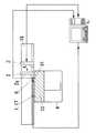
本実施形態は、以下の画像処理工程及び準備工程を経た後に、造形エリア1の外側の所定位置に配置された無機質もしくは有機質の粉末材料Pを材料供給ワイパー2によって造形エリア1に向かって移動させる移動工程と、造形エリア1に粉末材料Pを充填して均すことにより層状に堆積させる堆積工程と、堆積させた粉末材料Pに光ビームLを照射して硬化層Mを形成する光ビーム照射工程とを行ない、これら移動工程と堆積工程と光ビーム照射工程とを繰り返すことにより、硬化層Mを積み重ねて所望の三次元形状造形物を製造する方法であって、図1のように光ビーム照射工程の途中で、材料供給ワイパー2を移動させて次層分の粉末材料Pを光ビームLが照射されない非焼結エリアVに向かって移動させると共に粉末材料Pが焼結エリアU内に流出しない位置で材料供給ワイパー2を停止させる材料待機工程を行なう点に特徴を有している。
【0032】
先ず、画像処理工程では、積層造形を行なう前に図2に示す三次元の立体形状データを三次元CADコンピュータにて形状を作成する。次いで上記工程で作成された立体形状データを、三次元CAD断面スライス用CAMコンピュータを用いて、図3(a)、(b)のように積層方向(Z軸方向)に所定のピッチ(0.01mm〜0.5mm)でスライスし、図3(c)、(d)に示す断面輪郭データを抽出する。この断面輪郭データの輪郭はポイント位置データで構成される。ここで図3(a)(b)は積層方向(X−Z平面)の断面形状であり、図3(c)(d)はX−Y平面の断面であり、(c)が(b)のQ−Q線に沿う断面、(d)がW−W線に沿う断面である。
【0033】
次いで、上記断面スライスされた断面輪郭データを積層造形装置に転送する。このとき図4に示すネットワークにてデータのやり取りを行なう。なお、三次元CADコンピュータと三次元CAD断面スライス用CAMコンピュータとは同一のコンピュータであってもよい。その後、上記工程で転送された積層データを図5(a)に示す制御用コンピュータにて造形エリア1上にレイアウトする。図5(b)はレイアウト画面、(c)は断面移動後のレイアウト画面である。このとき断面輪郭を構成するポイントデータをコンピュータ数値入力で移動した値を付加することで、制御用コンピュータで造形を行なう断面輪郭データを数値入力にて移動させることが可能となる。
【0034】
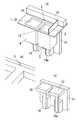
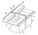
図6は上記造形を行なうための装置の一例を示している。材料タンク3内には材料テーブル12が材料テーブル駆動スライダー14aによって昇降可能に設置され、造形タンク4内には造形テーブル13が造形テーブル駆動スライダー14によって昇降可能に設置されている。造形テーブル13の上には造形物密着用プレート15が配置されており、粉末材料Pを光硬化させてなる硬化層M(図1)が順次積み重ねられて造形物が製造されるようになっている。粉末材料Pとしては、例えば平均粒径約20μmの球形をなす鉄粉が使用される。材料供給ワイパー2は、材料タンク3及び造形タンク4の内幅よりも長い細幅の板状をなし、ワイパー駆動スライダー16によって材料タンク3の外側から材料タンク3の上方を通過して造形エリア1の外側まで水平移動するようになっている。材料供給ワイパー2には、鉄製の平板が使用される。なお図6中の5は粉末材料Pの材料流出先端部P1(図1)を検知するための材料先端部検知センサー、10は材料先端部検知センサー5を駆動するセンサー駆動部、11は造形テーブル13及び材料テーブル12の駆動部保持用ベースプレートである。なお材料先端部検知センサー5については後述の実施形態で説明する。
【0035】
先ず図7のように造形テーブル13を開始位置にセットし、材料タンク3内に造形で必要な量の粉末材料Pをセットする。このとき、材料タンク3内に粉末材料Pを投入し、上面から圧力を加えて高密充填した後に上面を平坦に均す。またこのとき、材料供給ワイパー2を造形テーブル13上に移動させ、造形テーブル13を上昇させて造形物密着用プレート15を材料供給ワイパー2に接触させて、材料供給ワイパー2が造形物密着用プレート15全面に接触するように水平出しを行なう。その後、材料供給ワイパー2を材料供給準備位置(原点位置)に復帰させておく。この位置が材料供給ワイパー2の移動開始位置となる。
【0036】
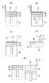
作業開始時には、造形タンク4では、図8(a)のように造形テーブル13の上面を造形タンク4の上端よりも1層分だけ下げてある。材料タンク3では、粉末材料Pが材料タンク3の上端よりも1層分だけ高い位置に押し上げられている。
【0037】
その後、粉末材料Pの移動工程→堆積工程→光ビーム照射工程へと移る。粉末材料Pの移動工程では、図8(b)のように材料供給ワイパー2を材料タンク3から造形タンク4のほうに水平移動させると、1層分の粉末材料Pが造形エリア1に押し出される。このとき材料供給ワイパー2の下端で均されるので、造形タンク4に供給された粉末材料Pは、薄い層状に堆積する。そして、図9(a)のように造形タンク4上に必要な粉末材料Pを供給し終えた材料供給ワイパー2は、造形タンク4の外側まで移動する。その後、図9(b)のように造形テーブル13を1層分だけ降下させてその上面をレーザー焼結位置(レーザー焼結焦点高さ)にセットする。その後、図9(c)のように材料供給ワイパー2が光ビームLの照射領域に入らないようにして元の位置まで移動させると共に、光ビームLを1層目の断面輪郭エリア上に照射してレーザー焼結を行ない、粉末材料Pを硬化させて新たな硬化層Mを形成する。光ビームLとしては、例えばYAGレーザが使用される。この光ビーム照射工程の間に、材料供給ワイパー2を材料タンク3の外側に復帰させておく。このとき材料供給ワイパー2が造形エリア1の外側に移動したことを確認する手段として、材料供給ワイパー2のスライド位置座標を制御用コンピュータで認識するか、材料供給ワイパー2が通過したことを認識させるためにセンサー等を設置して認識する方法がある。また、材料供給ワイパー2のスライド位置座標をコンピュータで認識して、図9(d)のように材料供給ワイパー2が断面輪郭エリアの外側に移動した直後からレーザー焼結を行なうことも可能である。そして、レーザー焼結完了後は、図9(e)のように造形テーブル13を1層分だけ降下させると共に、材料テーブル12を上昇させて粉末材料Pの押し出しを行なう。なお硬化層Mの1層分の厚みは、例えば0.1mmとする。ここまでは1層目の硬化層Mを形成する手順を説明したが、2層目以降からは以下のように光ビーム照射工程の途中で材料待機工程を行なうようにする。
【0038】
つまり、図10(a)に示す光ビーム照射工程の途中で、図10(b)、(c)のように材料供給ワイパー2を移動させて次層分の粉末材料Pを非焼結エリアV(材料供給ワイパー2の制御部で定めた非焼結エリアV、或いは造形状況を検出することにより求めた非焼結エリアV)に向かって移動させると共にこの粉末材料Pが焼結エリアU内に流出しない位置で材料供給ワイパー2を停止させる。図10(a)中の17は焼結完了部、18は焼結非完了部である。この材料待機工程では、図11に示すように、レーザー焼結を行なっている状態で、次層分の粉末材料Pが造形エリア1の非焼結エリアVまで押し出され、焼結エリアUの上面に流出しない位置で停止して材料供給準備を行なう。そして、レーザー焼結完了後に材料供給ワイパー2を移動させて造形タンク4上に粉末材料Pを供給することによって、造形エリア1上に粉末材料Pを短時間で供給できるようになり、このように光ビーム照射工程と材料待機工程とを同時進行させることで、造形タンク4上には複数層の硬化層Mが積み重ねられていき、所望の三次元形状を有する造形物が短時間で得られるようになる。
【0039】
しかして、光ビーム照射工程で断面輪郭エリア上にレーザー焼結を行なっている段階で、材料待機工程を同時進行させ、材料テーブル12を上昇させて次層に必要な材料分だけ材料供給ワイパー2にて押し出すと共に、この粉末材料Pが焼結エリアU上面に流出しないように材料供給ワイパー2の位置制御を行なうことによって、光ビーム照射工程を行なっている状態で造形エリア1上への次層の材料供給の準備ができるようになり、これにより、光ビーム照射工程が完了したあと直ぐに材料供給ワイパー2の移動による造形タンク4への粉末材料Pの供給が開始できるようになる。またこのとき図1のようにレーザー焼結を行なっている状態で、次層分の粉末材料Pの材料流出先端部P1が焼結エリアUの直前で停止させることにより、焼結エリアまでの次層分の材料供給を素早く開始することができるようになるので、造形タンク4上部に粉末材料Pが流出するのを防止しながら、造形時間を短縮でき、生産の高効率化を図ることができる。なお、必ずしも次層分の粉末材料Pの材料流出先端部P1を焼結エリアUの直前まで押し出す必要はなく、例えば図20に示すように、材料流出先端部P1を造形エリア1の直前で停止させるようにしてもよいものである。
【0040】
次に、材料待機工程において材料供給ワイパー2の位置制御の具体例を説明する。
【0041】
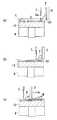
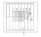
図12は、CAM処理で作成された造形物の断面輪郭データ(図3)と、断面輪郭データの造形エリア1上に配置される位置とに基づいて、造形エリア1上での焼結エリアUと非焼結エリアVとを特定して、材料供給ワイパー2の位置制御を行なう場合の一例を示している。ここでは、レイアウトした断面の断面輪郭データを構成するポイントデータa〜fを読み込み、造形エリア1座標で材料タンク3がある方向をX軸プラスとし、X座標の最大位置を焼結エリアUの先端部{材料流出先端部P1(図1)と同じ}とする。制御用コンピュータ画像では図12のcで示すポイントのX座標の値が焼結エリア先端部U1になり、これによって、材料供給ワイパー2の位置制御を行なうにあたって、材料供給位置設定を数値制御することが可能となる。これにより、材料待機工程において光ビームLによる1層分の照射が完了していない場合には、図13(a)のように粉末材料Pが焼結エリア先端部U1で停止し、図13(b)、(c)のように照射が完了した焼結エリアU毎に材料供給ワイパー2にて材料供給を行なえるようになる。またこのとき、材料供給ワイパー2を停止させることなく、光ビームの照射完了速度に合わせて移動させるようにしてもよいものである。このことは以下の各実施形態においても同様である。
【0042】
図14は、材料流出先端部P1が材料供給ワイパー2の先端部2aからどのくらいの幅を持っているかを造形前に確認し、その流出幅を流出量の最大値(幅D)と仮定して、材料供給ワイパー2の先端部2aに材料流出先端部P1を付加した座標を、材料供給準備位置とする場合の一例を示している。これにより、材料流出先端部P1が図14(a)のように材料タンク3と造形タンク4との間に位置するように、或いは図14(b)のように焼結エリアU直前に位置するように、材料流出量の幅Dに合わせて材料供給ワイパー2を位置制御することが可能となる。
【0043】
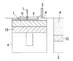
図15は前記図6で示した材料タンク3と造形タンク4との間に、材料流出先端部P1を検知する材料先端部検知センサー5を配置し、材料先端部検知センサー5が検知した位置と材料供給ワイパー2の先端部2aとから、材料流出量の幅Dを算出して材料供給ワイパー2の位置制御を行なう場合の一例を示している。ここでは、材料先端部検知センサー5で材料流出先端部P1を検知したときに、検知信号が制御用コンピュータに入力され、材料供給ワイパー2を停止させる。このときの材料流出先端部P1と材料供給ワイパー2の先端部2aとの間の距離を計算して、材料流出量の幅Dを算出する。このような距離測定を、1層毎もしくは複数層毎に随時行なうことによって、材料流出量の幅Dを正確に把握することが可能となり、結果的に材料供給ワイパー2の位置制御を精度良く行なうことが可能となる。
【0044】
図16は、造形テーブル13の降下量(積層ピッチ)と材料テーブル12の上昇量(造形タンク4上部に必要な供給量)とを予め設定し、図16(a)→(b)→(c)→(d)のように、造形エリア1上で10mmピッチで材料供給ワイパー2を移動させたときの材料供給ワイパー2の先端部2aと材料流出先端部P1との関係を実験する場合の一例を示し、図17はその関係をデータベース化した一例を示している。このデータを造形条件に付加し、造形を行なうことで、材料流出量の把握が容易となり、材料供給ワイパー2の位置制御が可能となる。その一例を以下の図18に示す。
【0045】
図18は、予め求められた材料供給ワイパー2の移動距離と材料供給ワイパー2の先端部2aから材料流出先端部P1までの距離との関係を示すデータ(図17のグラフ)に基づいて、材料供給ワイパー2の位置制御を行なう場合の一例を示している。ここでは、上記図15に示した材料先端部検知センサー5が材料供給ワイパー2の進行方向Aに沿ってスライド可能となっており、焼結エリア先端部U1に材料先端部検知センサー5を移動制御すると共に、焼結エリア先端部U1から材料供給ワイパー2の先端部2aまでの最短距離をCAM処理で作成された断面輪郭データから算出し、当該算出結果に基づいて材料供給ワイパー2を駆動する場合の例を示している。ここでは上記図17のグラフを活用することによって、焼結エリア先端部U1から材料供給ワイパー2の先端部2aまでの最短距離を算出するようにしている。なお図18中の16はワイパー駆動スライダー、17はセンサー駆動スライダーである。しかして、材料先端部検知センサー5をスライド可能としたことで、焼結エリア先端部U1の変化に材料先端部検知センサー5が対応できるようになり、材料流出量の数値を明確にでき、材料流出量の把握が容易となる。
【0046】
また、材料供給ワイパー2の位置制御方法の他例として、図18の材料先端部検知センサー5は用いず、造形エリア1の位置情報(断面輪郭エリアをレイアウトした制御用コンピュータの情報)とワイパー駆動スライダー16の位置情報をリンクすることで、材料供給ワイパー2を位置制御するようにしてもよい。図19はその一例を示しており、材料供給ワイパー2の移動距離を制御用コンピュータにフィードバックして材料供給ワイパー2のスライド位置座標{原点から進行方向A(X軸方向)への移動距離}を認識すると共に、次層分の粉末材料Pの最大流出量の幅Dの数値を予め入力しておき、焼結エリア先端部U1から材料供給ワイパー2の先端部2aまでの距離を算出して、当該距離が予め入力された材料流出量の幅Dと一致した時点で材料供給ワイパー2を停止させる。このように焼結エリア先端部U1と材料供給ワイパー2の先端部2aとの距離を制御用コンピュータで確認して材料供給ワイパー2を位置制御することで、材料先端部検知センサー5を用いることなく、制御用コンピュータの位置情報により材料供給ワイパー2の位置制御が可能となる。
【0047】
図21は、図12に示した断面輪郭データを、材料供給ワイパー2の進行方向Aに対して複数のエリアg〜l……に分割し、材料供給ワイパー2が進行を開始する方向Aから光ビーム照射を開始する場合の一例を示している。本例では10分割しているが、分割数は特に限定されない。しかして、光ビーム照射工程において、上記分割されたエリアのうち、材料供給ワイパー2が進行を開始する方向Aからg→h→i→j→k→l……の順にレーザー焼結を行なうことによって、分割ごとの焼結完了が把握でき、従って、焼結完了したエリアに次層分の粉末材料Pを押し出していくことによって、造形時間の一層の短縮化を図ることができる。
【0048】
図22は、上記図21のように輪郭データを材料供給ワイパー2の進行方向Aに対して複数分割した原理を用い、造形エリア1に材料供給ワイパー2が移動する時間を算出し、その時間からレーザー焼結を完了する時間を制御用コンピュータで算出し、焼結未完了の分割されたエリアにレーザー焼結が開始され始めたときに、焼結完了後の分割エリアに材料供給ワイパー2が材料供給を開始する場合の一例を示している。ここでは、1層分だけ造形テーブル13を降下して、光ビーム照射を行なっている状態で、次層分の粉末材料供給セットを行なうと共に、レーザー焼結完了時間を算出し、レーザー焼結完了時間と、材料供給ワイパー2が造形エリア1直前或いは焼結エリアU直前に移動する時間とが一致とすると、材料供給を開始する。これにより、材料供給時間(加工時間)が正確に算定できるようになる。また焼結が完了したエリアに次層分の粉末材料Pを押し出すことによって、造形時間の一層の短縮化を図ることができる。
【0049】
次に、材料待機工程において粉末材料Pを造形エリア1に流出させないための材料保管溝6を設けた場合の例を説明する。
【0050】
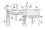
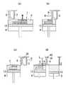
図23は、造形タンク4と材料タンク3との間に底面6aが昇降自在に駆動する材料保管溝6を設け、レーザー焼結時に材料保管溝6内に格納された粉末材料Pを上昇させると共に材料供給ワイパー2を移動させて該粉末材料Pを造形エリア1上に供給する場合の一例を示している。本例では、レーザー焼結時には、図23(a)のように材料供給ワイパー2によって押し出された次層分の粉末材料Pを材料保管溝6に保管しておき、レーザー焼結が完了したときに図23(b)のように材料保管溝6の下方に配置した溝テーブル40が上昇して、材料供給を開始するので、造形エリア1直前に材料供給準備をしたときでも、材料保管溝6に粉末材料Pが格納されることで、粉末材料Pが造形エリア1に流出しないものであり、焼結完了後は速やかに造形エリア1上に材料供給ができ、造形時間を短縮させることができる。
【0051】
図24は材料保管溝6の底面6aを、造形エリア1に近づくにつれて下り傾斜させた場合を示している。他の構成は図23と同様である。ちなみに、材料保管溝6の底面6aが平坦だと、底面6aが完全に上昇しきるまで材料供給ワイパー2の移動を待つ必要があるが、本例では、材料保管溝6の底面6aを造形エリア1に向かって下り傾斜させたので、図24(a)(b)のように溝テーブル40の上昇と材料供給ワイパー2の移動とを同時に行なうことで、粉末材料Pを造形エリア1上に押し出すことが可能となり、従って、材料供給ワイパー2の移動開始のタイミングを速めることができ、造形時間の一層の短縮化を図ることができる。
【0052】
図25は、上記材料保管溝6を造形タンク4の両サイドに設けた場合の例を示している。図25では材料保管溝6の底面6aは平坦面となっているが、図24のように造形タンク4に向かって下り傾斜させてもよいものである。本装置の一例を図30、図31に示している。本装置の溝テーブル40は図30(c)に例示したスライダー装置41によって昇降するものであるが、これに限らず、図30(b)、図31に例示したモータ20及びカム21を用いて昇降させるものであってもよい。材料保管溝6以外の構成は図6と同様である。しかして、造形タンク4の両サイドに設けた材料保管溝6にそれぞれ次層分の粉末材料Pを保管できるので、材料供給ワイパー2の1往復で2回の材料供給を行なうことが可能となり、材料供給ワイパー2を1往復させて1回の材料供給を行なう場合と比較して材料供給ワイパー2の移動距離を短くでき、造形時間をより短縮できる。
【0053】
図26は、上記両サイドの材料保管溝6のうち、一方(材料タンク3側)の材料保管溝6に「複数層(例えば6層)+1層」分の粉末材料Pを格納し、他方(材料タンク3側と反対側)の材料保管溝6に「複数層(例えば6層)」分の粉末材料Pを格納し、レーザー焼結が完了した後に材料供給ワイパー2を両方の材料保管溝6間に移動させることで造形エリア1上への材料供給を行なう場合の一例を示している。図26(a)のようにレーザー焼結を行なっている状態で、先ず材料タンク3を複数層分(ここでは12層分)だけ上昇させ、材料供給ワイパー2により12層分の粉末材料Pを一方(材料タンク3側)の材料保管溝6に供給する。レーザー焼結完了後に造形テーブル13を1層分だけ降下させた後に、図26(b)のように溝テーブル40を「(複数層/2)+1層」分(ここでは7層分)だけ上昇させて、材料供給ワイパー2で7層分の粉末材料Pを造形エリア1上を通過させて1層分の粉末材料Pを供給すると共に、過剰な6層分の粉末材料Pを他方(材料タンク3側と反対側)の材料保管溝6に格納して材料供給ワイパー2を他方の材料保管溝6の外側に配置する(図26(c)の状態)。その後、造形テーブル13を1層分だけ降下させた後に、図26(c)のようにレーザー焼結を行なう。レーザー焼結後に造形テーブル13を更に1層分だけ降下させた後に、図26(d)のように他方の材料保管溝6の溝テーブル40を1層分上昇させて、材料供給ワイパー2にて1層分の粉末材料Pを造形エリア1上に供給する。そして、材料保管溝6内に粉末材料Pがなくなるまで上記一連の動作((a)〜(d))を繰り返す(図26(e))。粉末材料Pがなくなった後に図26のように材料供給ワイパー2を原点位置に復帰させると共に、図26(a)〜(d)の動作を繰り返す。これにより、材料供給ワイパー2を両サイドの材料保管溝6間で複数回往復させるだけで、材料保管溝6内の粉末材料Pを(複数×2)回供給することが可能となり、材料供給の効率化が図られ、造形時間を一層短縮できるようになる。
【0054】
図27は、両サイドの材料保管溝6のうち、一方(材料タンク3側)の材料保管溝6に2層分以上の粉末材料Pを格納し、他方(材料タンク3側と反対側)の材料保管溝6に1層分の粉末材料Pを格納し、両サイドの材料保管溝6間に材料供給ワイパー2を往復移動させる場合を示している。両サイドの材料保管溝6の溝テーブル40が昇降する点は上記図26の実施形態と同様である。本例では図27(a)のように、一方の材料保管溝6に例えば6層分の粉末材料Pを格納した場合を説明すると、先ず図27(a)のようにレーザー焼結を行なっている状態で、材料供給ワイパー2を移動させると共に、溝テーブル40を2層分だけ上昇させて、材料供給ワイパー2で2層分の粉末材料Pを造形エリア1上を通過させて1層分の粉末材料Pを供給すると共に、過剰な1層分の粉末材料Pを他方(材料タンク3側と反対側)の材料保管溝6に格納し、材料供給ワイパー2を他方の材料保管溝6よりも更に他方に配置する(図27(c)の状態)。その後、造形テーブル13をレーザー焼結位置まで降下させてレーザー焼結を行なう。レーザー焼結後に造形テーブル13を1層分だけ降下させた後に、図27(d)のように他方の材料保管溝6の溝テーブル40を上昇させて、残りの粉末材料Pを材料供給ワイパー2にて造形エリア1上に供給する。このようにして、すべての材料保管溝6内に粉末材料Pがなくなるまで、上記一連の動作((a)〜(d))を繰り返す。これにより、材料保管溝6内の2層以上の粉末材料Pを造形エリア1上に順に供給可能となり、材料供給ワイパー2の移動距離(移動量)を削減でき、造形時間を短縮できる。しかも本例では、2層分の粉末材料Pを材料供給ワイパー2で押し出すので、押し出される粉末材料Pが少量であり、材料供給ワイパー2にかかる負担が小さくなり制御が容易になるという利点もある。
【0055】
また図28は、上記両サイドに材料保管溝6を設けた場合において、材料タンク3側と反対側の材料保管溝6の底面6aを造形エリア1に近づくにつれて下り傾斜させた場合を示している。ここでは材料タンク3側の材料保管溝6の底面6aは平坦としているが、この底面6aも上記図24のように傾斜させてもよいものである。しかして、材料供給ワイパー2の復路の場合、他方の材料保管溝6の底面6aを上昇させながら材料供給ワイパー2を移動させて粉末材料Pを造形エリア1上に押し出すことができるようになるので、復路での材料供給ワイパー2の移動開始のタイミングを速めることができ、造形時間を一層短縮できる。
【0056】
また図29は材料保管溝6の下部に振動ユニット部7を設けた場合を示している。他の構成は図27と同様である。本例では、材料保管溝6の底面6aのテーブルの下部に振動ユニット部7を設けたことで、材料保管溝6の底面6aに振動を与えて、材料保管溝6の粉末材料Pの充填を高密度で行なうことができ、材料供給量のバラツキを防止できる。なお振動ユニット部7として例えばソレノイド等を用いることができるが、その機構は特に限定されない。
【0057】
次に、材料供給ワイパー2とは別に材料格納遮蔽板8を設けた実施形態を説明する。
【0058】
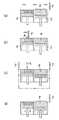
図32は材料タンク3と造形タンク4との間に材料格納遮蔽板8を配置し、材料タンク3上を通過する材料供給ワイパー2にて押し出された粉末材料Pを材料供給ワイパー2と材料格納遮蔽板8との間で挟み込みながら粉末材料Pを造形エリア1上に供給する場合の一例を示している。図33は材料格納遮蔽板8に接触確認センサー43を備えた場合の一例を示しており、材料格納遮蔽板8は2本のガイドレール19にてガイドされて材料タンク3および造形タンク4の上方空間を平行移動する。材料格納遮蔽板8の駆動源としては、材料格納遮蔽板8上部に設けた駆動制御モータ42に歯車22を設け、この歯車22を材料供給ワイパー2の進行方向Aと平行に設置されたラック23と噛み合わせてある。ラック23はワイパー駆動スライダー16に対して固定されている。駆動制御モータ42が回転すると、駆動制御モータ42及び材料格納遮蔽板8がラック23に対して移動するようになっている。レーザー焼結を行なっているときに、材料格納遮蔽板8と材料供給ワイパー2との位置関係を認識するために、材料格納遮蔽板8の上部に接触確認センサー43で位置情報を得るようにしている。つまり接触確認センサー43で得た位置信号で、造形エリア1上部に粉末材料Pを供給する時に材料供給ワイパー2と一定の距離を保ちながら、焼結エリア先端部U1に材料格納遮蔽8の先端部(造形タンク4側の先端部)を移動させるようにしている。他の構成は図6の構成と同様である。レーザー焼結が完了すると、図34(a)〜(c)のように材料格納遮蔽板8の先端部が次の焼結エリアU手前まで移動して、材料供給準備を行なう。しかして造形エリア1直前まで粉末材料Pが移動しても材料格納遮蔽板8によって造形エリア1内に粉末材料Pが流出するのを防止できる。材料供給時の流出量を把握しなくてもよいものとなり、材料供給ワイパー2の位置制御が簡単になる。
【0059】
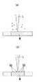
また上記材料格納遮蔽板8の形状は平板形状に限らず、図35に示すように、材料格納遮蔽板8の下端部8aをエッジ形状としたり、或いは図36に示すように、材料格納遮蔽板8の下端部8aをヤスリのような網目溝が付加された形状とすることで、レーザー焼結面(最上層の硬化層M上面)の突起部50(図38)を除去できるようになる。さらに図37に示すように、材料格納遮蔽板8の下端部8aに円筒のローラ24を付加し、ローラ24の外周部に設けた溝によってレーザー焼結面の突起部50を除去するようにしてもよい。ちなみに、レーザー焼結面の突起部50とは、図38のようにレーザー照射された材料が飛び跳ねて焼結された部分に飛び散った溶融玉をいい、この突起部50を除去することで硬化層M表面の平滑性を得ることができる。
【0060】
図39は材料格納遮蔽板8の下端部8aを材料供給ワイパー2側に向かって傾けた形状にした場合の一例を示している。なお、材料格納遮蔽板8の位置制御は図34と同様である。本例の材料格納遮蔽板8は2層構造とされ、材料供給ワイパー2側の下端部8aが材料供給ワイパー2側に向かって略く字状に屈曲しており、材料格納遮蔽板8の上部に接触確認センサー43が配設されている。この材料格納遮蔽板8を備えた装置の一例を図40に示す。図40(a)のように材料格納遮蔽板8の準備設定座標位置を認識する位置認識センサー部25が設けられている。他の構成は図33と同様である。この材料格納遮蔽板8の動作の一例を図41に示す。レーザー焼結を行なっている状態で、図41(a)のように材料格納遮蔽板8を材料タンク3と造形タンク4との間に停止させた状態で、ワイパー駆動スライダー16によって材料供給ワイパー2を移動して、図41(b)、(c)のように材料供給ワイパー2と材料格納遮蔽板8の下端部8aとの間で次層分の粉末材料Pを挟み込む。このとき接触確認センサー43が認識したときに材料格納遮蔽板8の下端部8aと材料供給ワイパー2との間に約0.5〜2mm程度の幅Eの隙間(図41(c))を設け、この隙間により粉末材料Pを焼結エリアU上に塗布する。従って、造形エリア1直前まで材料格納遮蔽板8が移動しても、粉末材料Pが流出しない。また本例では接触確認センサー43によって隙間の幅Eを設定することが可能である。また材料格納遮蔽板8の駆動制御モータ42の移動距離座標は制御用コンピュータにて座標認識を行なうことが可能である。
【0061】
図42は、材料タンク3と造形タンク4との間に配置される材料格納遮蔽板8と、材料タンク3上を通過する材料供給ワイパー2とを備え、材料格納遮蔽板8と材料供給ワイパー2とを接触離反可能とし、材料待機工程の中で材料供給ワイパー2にて押し出された粉末材料Pを材料供給ワイパー2と材料格納遮蔽板8との間で挟み込みながら粉末材料Pを造形エリア1上の焼結エリアUとその周辺部のみに塗布するための装置の一例を示している。他の構成は図40と同様である。本例の装置の動作状態の一例を図43、図44に示す。材料待機工程において、先ず図43(a)のように材料格納遮蔽板8は造形タンク4と材料タンク3との間で待機している状態で、材料タンク3が次層分上昇する。図43(b)(c)のように材料供給ワイパー2が材料タンク3上部に押し出された次層分の粉末材料Pを造形タンク4側に押し出し、材料格納遮蔽板8と材料供給ワイパー2との間で粉末材料Pを挟み込む。そして、材料格納遮蔽板8に設けた接触確認センサー43によって材料供給ワイパー2と材料格納遮蔽板8との位置認識をコンピュータ上で認識して、図43(d)のようにレーザー焼結される断面輪郭エリアより約15mm手前に材料供給ワイパー2を停止させる。つまり、材料供給ワイパー2の先端部2aから材料格納遮蔽板8の先端部での距離mを約10mmと仮定し、この距離mに材料格納遮蔽板8の幅Nを加えた値を約15mmと仮定する。この状態から、図43(e)のように材料供給ワイパー2から材料格納遮蔽板8を約0.5〜2mm前方に移動させて隙間を形成し、造形タンク4上に粉末材料Pを供給する準備を完了する。その後、断面輪郭データに対してレーザー焼結が完了した認識したデータを受けて、図43のように材料供給ワイパー2及び材料格納遮蔽板8を焼結が完了したエリア上まで移動して、材料供給ワイパー2と材料格納遮蔽板8との隙間から造形エリア1上に1層分の粉末材料Pだけを層状に堆積させる。その後断面輪郭データ上のエリアの焼結が完了すると、図44(a)の位置まで材料格納遮蔽板8及び材料供給ワイパー2を移動させ、焼結エリアUより約15mm進行方向Aに対して余分に粉末材料Pを供給する。その後、図44(b)のように材料供給ワイパー2と材料格納遮蔽板8とが進行方向Aに対して反対方向Bに進み、図44(c)のように材料格納遮蔽板8は位置認識センサー部25に接触したときに停止し、材料供給ワイパー2は図44(d)のように材料タンク3後方の原点位置に復帰し、図43(a)のレーザー焼結が開示されると共に、上記図43(a)〜図44(d)の動作を繰り返す。ここで、非焼結エリアVでは材料格納遮蔽板8と材料供給ワイパー2との隙間をなくすことで、粉末材料Pが非焼結エリアVには供給されないようにすることができ、造形エリア1直前まで粉末材料Pが移動しても材料格納遮蔽板8によって造形エリア1内に粉末材料Pが流出するのを防止できる結果、材料供給時の流出量を把握しなくてもよくなる。また焼結エリアUでは、材料格納遮蔽板8と材料供給ワイパー2とを離してその隙間から粉末材料Pを供給することで、焼結エリアUとその周辺部のみに粉末材料Pを供給することが可能となり、材料供給量が少なくて済み、材料供給を効率良く行なうことができる。
【0062】
図45は材料格納遮蔽板8を材料供給ワイパー2の前後両サイドに設け、前側の材料格納遮蔽板8と材料供給ワイパー2の前面との間、後側の材料格納遮蔽板8と材料供給ワイパー2の背面との間に、それぞれ、粉末材料Pを保管し、造形タンク4上部を往復移動させる場合の一例を示し、図46、図47はその装置の一例を示している。後側の材料格納遮蔽板8の移動機構は前側の材料格納遮蔽板8と同様であり、ラック23に噛み合う歯車22を備えた駆動制御モータ42にて駆動制御されると共に、位置認識センサー部25にて位置が認識されるようになっている。この後側の材料格納遮蔽板8にも接触確認センサー43が設けられている。また本例では、材料待機工程において、先ず図48(a)のように前側の材料格納遮蔽板8は造形タンク4と材料タンク3との間で停止し、後側の材料格納遮蔽板8が材料供給ワイパー2の後方で停止している状態で、材料タンク3が1層分だけ上昇する。図48(b)のように材料供給ワイパー2が次層分の粉末材料Pを造形タンク4側に押し出して材料供給ワイパー2との間でその粉末材料Pを挟み込む。その後、材料タンク3が更に1層分だけ上昇して、図48(c)のように後側の材料格納遮蔽板8がその粉末材料Pを造形タンク4側に押し出して材料供給ワイパー2との間で粉末材料Pを挟み込み、材料供給準備を完了する。その後、レーザー焼結後に図48(d)のように造形エリア1上に前側の材料格納遮蔽板8と材料供給ワイパー2と後側の材料格納遮蔽板8とを一体に移動させる。このとき材料供給ワイパー2と前側の材料格納遮蔽板8との隙間から造形エリア1上には1層分の粉末材料Pだけを層状に堆積させる。このとき材料供給ワイパー2と後側の材料格納遮蔽板8との間は接触している。その後図49(a)の位置まで前側の材料格納遮蔽板8と材料供給ワイパー2と後側の材料格納遮蔽板8とをそれぞれ移動させた後に、図49(b)のようにレーザー焼結を行ない、レーザー焼結完了後に、図49(c)のように前側の材料格納遮蔽板8と材料供給ワイパー2と後側の材料格納遮蔽板8とが進行方向Aに対して反対方向Bに進み、後側の材料格納遮蔽板8と材料供給ワイパー2との隙間から1層分の粉末材料Pを造形エリア1へと移送して層状に堆積させる。そして図49(d)のように前側の材料格納遮蔽板8が位置認識センサー部25に接触して停止し、材料供給ワイパー2と後側の材料格納遮蔽板8とが図48(a)に示す材料タンク3後方の原点位置に復帰し、上記一連の動作を繰り返す。しかして、2層分の粉末材料Pを保管しながら材料供給ワイパー2と前側の材料格納遮蔽板8と後側の材料格納遮蔽板8とを造形エリア1上を1往復させるだけで、2層分の材料が順次供給可能となり、1回の硬化工程毎に材料供給ワイパー2を1回往復させる場合と比べて、材料供給ワイパー2の無駄な動きが少ないので、迅速な動作が可能となり、全体の作業時間が削減され、作業効率が向上する。
【0063】
図50は造形エリア1に粉末材料Pが供給されているか否かを把握するために、レーザー焼結するチャンバー内上部にカメラユニット部9を設置し、材料供給後に造形エリア1上に材料が供給されているか否かを確認し、また材料が完全に供給されていないときは再度材料を供給する場合の一例を示している。本例では、図50(b)の左側に示す材料供給が完全にされた画像のときは次層のレーザー焼結を行ない、同(b)の右側に示す材料供給が不完全な場合の画像(Tで示す影)のときは再度材料供給を行ない、その後再度カメラで撮影して、材料供給が完全となった後に、次層のレーザー焼結を行なうようにする。これにより材料供給漏れが少なくなり、造形物の高品質化を図ることができる。
【0064】
【発明の効果】
上述のように請求項1記載の発明にあっては、造形エリアの外側の所定位置に配置された無機質もしくは有機質の粉末材料を材料供給ワイパーによって造形エリアに向かって移動させる移動工程と、造形エリアに粉末材料を充填して均すことにより層状に堆積させる堆積工程と、堆積させた粉末材料に光ビームを照射して硬化層を形成する光ビーム照射工程とを繰り返すことにより、硬化層を積み重ねて所望の三次元形状造形物を製造する方法であって、上記光ビーム照射工程の途中で、材料供給ワイパーを移動させて次層分の粉末材料を光ビームが照射されない非焼結エリアに向かって移動させると共に粉末材料が焼結エリア内に流出しない位置で材料供給ワイパーを停止させる材料待機工程を行なうので、光ビーム照射を行なっている状態で、材料供給ワイパーにて次層分の粉末材料を造形エリア上の焼結エリアの上面に流出しない位置まで押し出して待機させることによって、造形エリア上への次層の材料供給の準備ができるようになり、これにより造形時の材料供給時間を更に短縮でき、生産の高効率化を図ることができるものである。
【0067】
また上記粉末材料を溜める材料タンクと硬化層を造形する造形タンクとの間に、材料供給ワイパーにて押し出された粉末材料の材料流出先端部を検知する材料先端部検知センサーを配置し、材料先端部検知センサーが検知した位置と材料供給ワイパーの先端部とから、材料流出量の幅を算出して材料供給ワイパーの位置制御を行なうので、材料流出先端部と材料供給ワイパーの先端部との間の距離測定を随時行なうことができ、材料流出量を把握することができる。
【0068】
また請求項2記載の発明は、請求項1記載の効果に加えて、材料先端部検知センサーが材料供給ワイパーの進行方向に沿ってスライド可能とされ、焼結エリア先端部と対応する位置に材料先端部検知センサーを移動制御すると共に、焼結エリア先端部から材料供給ワイパーの先端部までの最短距離をCAM処理で作成された断面輪郭データから算出し、当該算出結果に基づいて材料供給ワイパーを駆動するので、材料先端部検知センサーをスライド可能としたことで、焼結エリア先端部の変化に材料先端部検知センサーが対応できるようになり、造形エリアの形状変化に応じて材料流出量の数値が明確となり、材料流出量を把握することができる。
【0073】
また、請求項3記載の発明は、造形エリアの外側の所定位置に配置された無機質もしくは有機質の粉末材料を材料供給ワイパーによって造形エリアに向かって移動させる移動工程と、造形エリアに粉末材料を充填して均すことにより層状に堆積させる堆積工程と、堆積させた粉末材料に光ビームを照射して硬化層を形成する光ビーム照射工程とを繰り返すことにより、硬化層を積み重ねて所望の三次元形状造形物を製造する装置であって、上記粉末材料を溜める材料タンクと硬化層を造形する造形タンクとの間に底面が昇降自在に駆動する材料保管溝を設け、レーザー焼結時に材料保管溝内に格納された粉末材料を上昇させると共に材料供給ワイパーを移動させ且つ粉末材料が焼結エリア内に流出しない位置で材料供給ワイパーを停止させるための制御部を設けてなるので、レーザー焼結時に材料供給ワイパーによって押し出された次層分の粉末材料を材料保管溝に保管し、レーザー焼結が完了したときに材料保管溝の底面を上昇させて材料供給を開始することができ、これにより、造形エリア直前に材料供給準備をしたときでも、材料保管溝に粉末材料が格納されることで、粉末材料が造形エリアに流出しないものであり、焼結完了後は速やかに造形エリア上に材料供給ができ、造形時間を短縮させることができる。
【0074】
また請求項4記載の発明は、請求項3記載の効果に加えて、上記材料保管溝の底面を、造形エリアに近づくにつれて下り傾斜させたので、材料保管溝の底面の上昇と材料供給ワイパーの移動とを同時に行なうことで、粉末材料を造形エリア上に押し出すことが可能となり、従って、材料供給ワイパーの移動開始のタイミングを速めることができ、造形時間を一層短縮できる。
【0075】
また請求項5記載の発明は、請求項3又は4記載の効果に加えて、上記材料保管溝を造形タンクの両サイドに設けたので、材料供給ワイパーの1往復で2回の材料供給を行なうことが可能となり、材料供給ワイパーの移動距離を短くでき、造形時間を一層短縮できる。
【0076】
また請求項6記載の発明は、請求項5記載の効果に加えて、上記両サイドの材料保管溝のうち、材料タンク側の材料保管溝に「複数層+1層」分の粉末材料を格納し、材料タンク側とは反対側の材料保管溝に上記「複数層」と同数の「複数層」の粉末材料を格納し、レーザー焼結が完了した後に材料供給ワイパーを両方の材料保管溝間に移動させることで造形エリア上への材料供給を行なうので、材料供給ワイパーを両サイドの材料保管溝間で複数回往復させるだけで、材料保管溝内の粉末材料を複数回供給することが可能となり、材料供給ワイパーの移動距離(移動量)をより削減でき、作業能率を向上させて、造形時間を一層短縮できるものである。
【0077】
また請求項7記載の発明は、請求項3又は4又は5又は6記載の効果に加えて、材料保管溝の下部に振動ユニット部を設けたので、材料保管溝の底面に振動を与えて、材料保管溝の粉末材料の充填を高密度で行なうことができ、材料供給量のバラツキを防止できる。
【0078】
また請求項8記載の発明は、請求項1記載の効果に加えて、上記硬化層を造形する造形タンクの両サイドに底面が昇降自在に駆動する材料保管溝をそれぞれ設け、材料タンク側の材料保管溝に2層分以上の粉末材料を格納すると共に、材料タンク側と反対側の材料保管溝に1層分の粉末材料を格納し、両サイドの材料保管溝間に材料供給ワイパーを往復移動させるので、材料保管溝内の2層以上の粉末材料を造形エリア上に1層ずつ順次供給可能となり、従って、材料供給ワイパーの移動距離(移動量)を削減でき、作業能率を向上させて、造形時間を短縮できる。
【0079】
また請求項9記載の発明は、請求項8記載の効果に加えて、上記両サイドの材料保管溝の少なくとも一方の底面を造形エリアに近づくにつれて下り傾斜させると共に、下り傾斜した底面の上昇と材料供給ワイパーの移動とを同時に行なうことで、粉末材料を造形エリア上に押し出すので、材料供給ワイパーの移動開始のタイミングを速めることができ、作業能率を向上させて、造形時間の一層の短縮化を図ることができる。
【0080】
また請求項10記載の発明は、造形エリアの外側の所定位置に配置された無機質もしくは有機質の粉末材料を材料供給ワイパーによって造形エリアに向かって移動させる移動工程と、造形エリアに粉末材料を充填して均すことにより層状に堆積させる堆積工程と、堆積させた粉末材料に光ビームを照射して硬化層を形成する光ビーム照射工程とを繰り返すことにより、硬化層を積み重ねて所望の三次元形状造形物を製造する装置であって、上記粉末材料を溜める材料タンクと硬化層を造形する造形タンクとの間に材料格納遮蔽板を配置し、レーザー焼結時に材料供給ワイパーにて押し出された粉末材料を材料供給ワイパーと材料格納遮蔽板との間で挟み込み、レーザー焼結完了後に粉末材料を造形エリア上に供給するための制御部を設けてなるので、造形エリア直前まで粉末材料が移動しても材料格納遮蔽板によって造形エリア内に粉末材料が流出するのを防止できるので、材料供給時の流出量を把握しなくてもよく、材料供給ワイパーの位置制御が簡単になる。
【0081】
また請求項11記載の発明は、請求項10記載の効果に加えて、上記材料格納遮蔽板の先端部を材料供給ワイパー側に向かって傾けた形状にしたので、材料供給ワイパーと材料格納遮蔽板との間で次層分の粉末材料を挟み込むことができ、造形エリア直前まで材料格納遮蔽板が移動しても粉末材料が流出しないようにできる。
【0082】
また請求項12記載の発明は、請求項10記載の効果に加えて、上記材料格納遮蔽板の先端部を材料供給ワイパーに対して接触離反可能とし、材料待機工程の中で材料供給ワイパーにて押し出された粉末材料を材料供給ワイパーと材料格納遮蔽板との間で挟み込むと共に、材料格納遮蔽板の先端部と材料供給ワイパーとの隙間から粉末材料を造形エリア上の焼結エリアとその周辺部に供給するので、造形エリア直前まで粉末材料が移動しても材料格納遮蔽板と材料供給ワイパーとの隙間をなくすことで造形エリア内に粉末材料が流出するのを防止できるので材料供給時の流出量を把握しなくてもよく、供給時には材料格納遮蔽板と材料供給ワイパーとの間に隙間を設けることで造形エリア上の焼結エリアとその周辺部のみに粉末材料を供給することが可能となり、材料供給の効率化を図ることができる。
【0083】
また請求項13記載の発明は、請求項10又は11又は12記載の効果に加えて、材料格納遮蔽板を材料供給ワイパーの前後両サイドに設けたので、前側の材料格納遮蔽板と材料供給ワイパーとの間に次層分の粉末材料を保管すると共に、後側の材料格納遮蔽板と材料供給ワイパーとの間に次々層の粉末材料を保管して、造形エリア上を往復させることで、2層分の材料が順次供給可能となり、作業能率を向上させて、造形時間をより短縮できるようになる。
【0084】
また請求項14記載の発明は、請求項1又は2又は8又は9記載の効果に加えて、レーザー焼結するチャンバー内上部にカメラユニット部を設置し、材料供給後に造形エリア上に材料が完全に供給されていないときは再度材料を供給するので、材料供給が完全にされた画像のときは次層のレーザー焼結を行ない、材料供給が不完全な場合の画像のときは再度材料供給を行ない、再度カメラで撮影して材料供給が完全となった後に、次層のレーザー焼結を行なうようにすることで、造形エリアに粉末材料が供給されているか否かを把握することができる結果、材料供給漏れが少なくなり、造形物の高品質化を図ることができる。
【図面の簡単な説明】
【図1】本発明の実施形態の一例を示す断面図である。
【図2】同上の三次元CADにて形成された立体形状データの説明図である。
【図3】(a)(b)は三次元立体形状とその形状をスライスする場合の説明図、(c)(d)は抽出された断面輪郭データの一例であり、(c)は(b)のQ−Q線断面図、(d)は(b)のW−W線断面図である。
【図4】同上の断面輪郭データをやり取りするネットワークの説明図である。
【図5】(a)〜(c)は同上の断面輪郭データを制御用コンピュータにてレイアウトする場合の説明図である。
【図6】(a)は同上の造形を行なう装置の斜視図、(b)は材料先端部検知センサー付近の拡大斜視図、(c)は材料テーブル及び造形テーブルを駆動するスライダー部分の斜視図である。
【図7】同上の造形テーブル及び材料テーブルを開始位置にセットした状態の説明図である。
【図8】(a)(b)は同上の材料供給ワイパーの移動状態の説明図である。
【図9】(a)は材料供給完了状態を示し、(b)は1層分だけ造形テーブルを降下させた状態を示し、(c)は材料供給ワイパーを原点位置に復帰させると共に断面輪郭エリアに光ビームを照射してレーザー焼結を行なう状態を示し、(d)は光ビームの照射と材料供給ワイパーの復帰を同時に行なう状態を示し、(e)は材料供給ワイパーが造形エリアの外側に移動した状態を示す図である。
【図10】(a)〜(c)は同上の材料待機工程の説明図である。
【図11】同上の材料待機工程において、材料流出先端部を焼結エリアの手前に位置させた場合の説明図である。
【図12】同上の焼結エリア先端部におけるポイントデータの説明図である。
【図13】(a)〜(c)は同上の粉末材料供給の動作説明図である。
【図14】(a)(b)は同上の材料供給ワイパーと材料流出幅との関係を説明する図である。
【図15】(a)(b)は同上の材料先端部検知センサーの斜視図及び側面図、(c)は材料先端部検知センサーにて材料流出先端部を検知して材料供給ワイパーを停止させた場合の説明図である。
【図16】(a)〜(d)は同上の材料流出先端部と材料供給ワイパーの先端部との距離と、材料供給ワイパーの移動距離との関係を示す図である。
【図17】同上の材料流出先端部と材料供給ワイパーの先端部との距離と、材料供給ワイパーの移動距離との関係を示すグラフである。
【図18】同上の材料先端部検知センサーをスライド可能とした場合の説明図である。
【図19】同上の造形エリアの位置情報と材料供給ワイパーのスライダー位置情報とから材料供給ワイパーの位置制御を行なう場合の説明図である。
【図20】同上の材料流出先端部を焼結エリア直前で停止させる場合の説明図である。
【図21】同上のCAD断面輪郭データを材料供給ワイパーが移動する進行方向に分割し、分割されたエリアを上記進行方向からレーザー焼結を行なう場合の一例の説明図である。
【図22】同上のレーザー焼結を開始から材料供給ワイパーが材料供給を開始する場合の説明図である。
【図23】(a)(b)は同上の材料タンクと造形タンクの間に材料保管溝を設けた場合の説明図である。
【図24】(a)(b)は同上の材料保管溝の底面を傾斜させた場合の説明図である。
【図25】同上の材料保管溝を造形タンクの両サイドに設けた場合の説明図である。
【図26】(a)〜(f)は図25の工程図である。
【図27】(a)〜(d)は同上の材料保管溝に複数層分の粉末材料を保管する場合の工程図である。
【図28】同上の造形タンクの外側の材料保管溝の底面を傾斜させた場合の説明図である。
【図29】同上の材料保管溝に振動を与える振動ユニット部を設けた場合の説明図である。
【図30】(a)は同上の造形タンクの両サイドに材料保管溝を設けた装置の斜視図、(b)は溝テーブルの昇降スライダーの説明図、(c)はモータとカムを用いて溝テーブルを昇降させる場合の説明図である。
【図31】(a)(b)は同上のモータとカムを用いて溝テーブルを昇降させる場合の正面断面図及び側面図、(c)はカムの正面図である。
【図32】同上の材料供給ワイパーの前方に材料格納遮蔽板を配置した場合の説明図である。
【図33】(a)(b)は同上の材料格納遮蔽板を備えた装置の斜視図、及び拡大斜視図である。
【図34】(a)〜(c)は同上の材料格納遮蔽板の動作説明図である。
【図35】同上の材料格納遮蔽板の他例の斜視図である。
【図36】(a)は同上の材料格納遮蔽板の更に他例の斜視図、(b)は底面図である。
【図37】同上の材料格納遮蔽板の更に他例の斜視図である。
【図38】(a)(b)は同上のレーザー焼結面の突起部の説明図である。
【図39】同上の材料格納遮蔽板の先端部をく字状に屈曲させた場合の説明図である。
【図40】(a)は同上の先端部がく字状に屈曲した材料格納遮蔽板を備えた装置の斜視図、(b)は拡大斜視図である。
【図41】(a)〜(c)は同上の材料格納遮蔽板の動作説明図である。
【図42】同上の材料格納遮蔽板と材料供給ワイパーとを接離自在とした装置の斜視図である。
【図43】(a)〜(f)は図42の装置を用いて粉末材料を供給する動作の説明図である。
【図44】(a)〜(d)は図42の装置を用いて粉末材料を供給する動作の説明図である。
【図45】同上の材料供給ワイパーの背後に後側の材料格納遮蔽板を設けた場合の説明図である。
【図46】(a)は同上の後側の材料格納遮蔽板を備えた装置の斜視図、(b)は拡大斜視図である。
【図47】同上の後側の材料格納遮蔽板と材料供給ワイパーと前側の材料格納遮蔽板とが重なり合った状態の斜視図である。
【図48】(a)〜(d)は同上の装置を用いて粉末材料を供給する動作の説明図である。
【図49】(a)〜(d)は同上の装置を用いて粉末材料を供給する動作の説明図である。
【図50】(a)は同上の造形エリア上の材料供給状況をカメラユニット部で撮影する場合の説明図、(b)は焼結されたカメラ画像において材料供給が完全にされた場合と不完全な場合の説明図である。
【図51】(a)〜(d)は従来例の説明図である。
【符号の説明】
1 造形エリア
2 材料供給ワイパー
3 材料タンク
4 造形タンク
5 材料先端部検知センサー
6 材料保管溝
6a 底面
7 振動ユニット部
8 材料格納遮蔽板
9 カメラユニット部
A 進行方向
L 光ビーム
M 硬化層
P 粉末材料
P1 材料流出先端部
U 焼結エリア
V 非焼結エリア[0001]
BACKGROUND OF THE INVENTION
The present invention relates to a method for producing a desired three-dimensional shaped object by depositing inorganic or organic powder materials in layers in a modeling area, irradiating a light beam to form a cured layer, and stacking the cured layers, The present invention relates to a manufacturing apparatus.
[0002]
[Prior art]
Prior art relating to a method of manufacturing a three-dimensional shaped object by irradiating a light beam (directed energy beam, laser) to inorganic powder (metal) or organic powder (resin) and curing it, and laminating a hardened layer. This is disclosed in Japanese Patent No. 2620353.
[0003]
Usually, the design of a part manufactured by the above method is performed by three-dimensional CAD. Based on the cross-sectional shape data of each layer generated by slicing the designed 3D CAD model to the desired layer thickness, the laser path of each layer is determined and the powder for one layer is sintered (hardened). At the same time, the part shape is manufactured by sintering (bonding) to the immediately preceding layer and continuously stacking the layers.
[0004]
In this method, a shape designed by three-dimensional CAD can be manufactured without a CAM device that has been conventionally used for manufacturing such a three-dimensional shaped object. Moreover, compared with the conventional methods, such as cutting, there exists a big merit at the point which can manufacture a desired component rapidly.
[0005]
However, the three-dimensional shaped object manufactured by the above method has only a reciprocating motion of the material supply mechanism when the powder material to be cured is distributed to the laser beam directing surface, and passes through the upper part of the modeling area. Therefore, the material supply mechanism stands by during the light beam irradiation, and once the irradiation is completed, the material supply mechanism returns to the original position, and then the powder supply operation is performed. Therefore, there is a problem that the material supply process time becomes long, and accordingly, the modeling time becomes long.
[0006]
In view of this, in the Japanese Patent Application Laid-Open No. 2001-150557, the applicant arranges the
[0007]
[Problems to be solved by the invention]
However, in the conventional example disclosed in Japanese Patent Laid-Open No. 2001-150557, the
[0008]
The present invention was invented in view of the problems of the conventional example described above, and the object of the present invention is three-dimensional shape modeling that can further shorten the modeling time and increase the production efficiency. An object of the present invention is to provide a method for manufacturing a product and a manufacturing apparatus therefor.
[0009]
[Means for Solving the Problems]
In order to solve the above-mentioned problem, in the present invention, a moving step of moving the inorganic or organic powder material P arranged at a predetermined position outside the
[0013]
Further, the material front
[0018]
Moreover, in this invention, the movement process which moves the inorganic or organic powder material P arrange | positioned in the predetermined position of the outer side of a modeling area toward a modeling area by the
[0019]
The
[0020]
The
[0021]
Of the
[0022]
Further, it is preferable to provide the vibration unit portion 7 below the
[0023]
Moreover, in this invention, the movement process which moves the inorganic or organic powder material P arrange | positioned in the predetermined position of the outer side of a modeling area toward a modeling area by the
[0024]
In addition, the
[0025]
Moreover, in this invention, the movement process which moves the inorganic or organic powder material P arrange | positioned in the predetermined position outside the modeling area toward the modeling area by the
[0026]
In addition, it is preferable that the
[0027]
Further, the
[0028]
Further, since the material
[0029]
In addition, it is preferable to install the
[0030]
DETAILED DESCRIPTION OF THE INVENTION
Hereinafter, the present invention will be described based on embodiments shown in the accompanying drawings.
[0031]
In the present embodiment, after passing through the following image processing process and preparation process, the inorganic or organic powder material P arranged at a predetermined position outside the
[0032]
First, in the image processing step, the shape of the three-dimensional solid shape data shown in FIG. 2 is created by a three-dimensional CAD computer before the additive manufacturing is performed. Next, the three-dimensional shape data created in the above process is converted into a predetermined pitch (0...) In the stacking direction (Z-axis direction) as shown in FIGS. 3A and 3B using a CAM computer for three-dimensional CAD cross section slicing. (01 mm to 0.5 mm) and slice contour data shown in FIGS. 3C and 3D are extracted. The contour of the cross-sectional contour data is composed of point position data. Here, FIGS. 3A and 3B are cross-sectional shapes in the stacking direction (XZ plane), FIGS. 3C and 3D are cross-sections in the XY plane, and FIG. (D) is a cross section along the WW line.
[0033]
Next, the cross-sectional profile data that has been sliced is transferred to the additive manufacturing apparatus. At this time, data is exchanged on the network shown in FIG. The three-dimensional CAD computer and the three-dimensional CAD section slicing CAM computer may be the same computer. Thereafter, the laminated data transferred in the above process is laid out on the
[0034]
FIG. 6 shows an example of an apparatus for performing the modeling. A material table 12 is installed in the
[0035]
First, as shown in FIG. 7, the modeling table 13 is set at the start position, and an amount of the powder material P necessary for modeling is set in the
[0036]
At the start of work, in the
[0037]
Thereafter, the process proceeds from the moving process of the powder material P to the deposition process → the light beam irradiation process. In the process of moving the powder material P, when the
[0038]
That is, in the middle of the light beam irradiation step shown in FIG. 10A, the
[0039]
Thus, at the stage where laser sintering is performed on the cross-sectional outline area in the light beam irradiation process, the material standby process is simultaneously performed, the material table 12 is raised, and the
[0040]
Next, a specific example of the position control of the
[0041]
FIG. 12 shows the sintering area U on the
[0042]
FIG. 14 confirms how wide the material outflow tip P1 is from the
[0043]
FIG. 15 shows a position where the material
[0044]
FIG. 16 sets in advance a descending amount (stacking pitch) of the modeling table 13 and an increasing amount of the material table 12 (a supply amount necessary for the upper part of the modeling tank 4), and FIG. 16 (a) → (b) → (c ) → Example of the case of experimenting the relationship between the
[0045]
FIG. 18 is based on data (graph of FIG. 17) showing the relationship between the movement distance of the
[0046]
Further, as another example of the position control method of the
[0047]
21 divides the cross-sectional contour data shown in FIG. 12 into a plurality of areas g to l... With respect to the traveling direction A of the
[0048]
FIG. 22 calculates the time for the
[0049]
Next, an example in which the
[0050]
In FIG. 23, a
[0051]
FIG. 24 shows a case where the
[0052]
FIG. 25 shows an example in which the
[0053]
FIG. 26 shows that the
[0054]
FIG. 27 shows that two or more layers of powder material P are stored in the
[0055]
FIG. 28 shows a case where the
[0056]
FIG. 29 shows a case where the vibration unit portion 7 is provided below the
[0057]
Next, an embodiment in which a material
[0058]
In FIG. 32, a material
[0059]
The shape of the material
[0060]
FIG. 39 shows an example in which the
[0061]
42 includes a material
[0062]
45, the material
[0063]
In FIG. 50, in order to grasp whether or not the powder material P is supplied to the
[0064]
【The invention's effect】
As described above, in the first aspect of the invention, the moving step of moving the inorganic or organic powder material arranged at a predetermined position outside the modeling area toward the modeling area by the material supply wiper, and the modeling area The hardened layer is stacked by repeating a deposition process in which the powder material is filled and leveled to deposit a layer and a light beam irradiation process in which the deposited powder material is irradiated with a light beam to form a hardened layer. In the method of manufacturing a desired three-dimensional shaped object, the material supply wiper is moved during the light beam irradiation step so that the powder material for the next layer is directed to a non-sintered area where the light beam is not irradiated. The material standby process is performed to stop the material supply wiper at a position where the powder material does not flow into the sintering area and the light beam irradiation is performed. Then, the material supply wiper pushes the powder material for the next layer to the position where it does not flow out to the upper surface of the sintering area on the modeling area, and makes it ready for material supply of the next layer on the modeling area. Thus, the material supply time during modeling can be further shortened, and the production efficiency can be improved.
[0067]
Also aboveA material tip detection sensor that detects the material outflow tip of the powder material pushed out by the material supply wiper is placed between the material tank that stores the powder material and the modeling tank that forms the hardened layer, and detects the material tip. Since the position of the material supply wiper is controlled by calculating the width of the material outflow amount from the position detected by the sensor and the tip of the material supply wiper, the distance between the material outflow tip and the material supply wiper tip Measurement can be performed at any time, and the amount of material outflow can be ascertained.
[0068]
AlsoClaim 2The described inventionClaim 1In addition to the effects described above, the material tip detection sensor can be slid along the direction of movement of the material supply wiper, and the material tip detection sensor is moved and controlled to a position corresponding to the tip of the sintering area and sintered. The shortest distance from the tip of the area to the tip of the material supply wiper is calculated from the cross-sectional contour data created by the CAM process, and the material supply wiper is driven based on the calculation result, allowing the material tip detection sensor to slide As a result, the material tip detection sensor can respond to changes in the sintering area tip, and the numerical value of the material outflow amount becomes clear according to the shape change of the modeling area, and the material outflow amount can be grasped. it can.
[0073]
Also,Claim 3The described invention includes a moving step in which an inorganic or organic powder material arranged at a predetermined position outside the modeling area is moved toward the modeling area by a material supply wiper, and the modeling area is filled with the powder material and leveled. By repeating the deposition process for depositing in a layered manner and the light beam irradiation process for irradiating the deposited powder material with a light beam to form a cured layer, the cured layers are stacked to produce a desired three-dimensional shaped object. The material storage groove is provided between the material tank for storing the powder material and the modeling tank for modeling the hardened layer, and the bottom surface is driven to be movable up and down, and stored in the material storage groove at the time of laser sintering. A control unit for raising the powder material and moving the material supply wiper and stopping the material supply wiper at a position where the powder material does not flow into the sintering area. Therefore, the powder material of the next layer extruded by the material supply wiper during laser sintering is stored in the material storage groove, and when laser sintering is completed, the bottom surface of the material storage groove is raised to supply the material. As a result, even when the material supply is prepared immediately before the modeling area, the powder material is stored in the material storage groove, so that the powder material does not flow into the modeling area, and after the sintering is completed. Can quickly supply the material onto the modeling area, thereby shortening the modeling time.
[0074]
AlsoClaim 4The described inventionClaim 3In addition to the effects described above, the bottom surface of the material storage groove is inclined downward as it approaches the modeling area, so that the powder material is formed by simultaneously raising the bottom surface of the material storage groove and moving the material supply wiper. It is possible to push out onto the area, so that the timing of starting the movement of the material supply wiper can be accelerated and the modeling time can be further shortened.
[0075]
AlsoClaim 5The described
[0076]
AlsoClaim 6The described inventionClaim 5In addition to the effects described above, among the material storage grooves on both sides, the material storage groove on the material tank side stores the powder material for “multiple layers + 1 layer”, and the material storage groove on the side opposite to the material tank side The same number of “multiple layers” of powder material is stored in the above, and after the laser sintering is completed, the material supply wiper is moved between both material storage grooves to supply the material onto the modeling area. Therefore, it is possible to supply the powder material in the material storage groove multiple times by simply reciprocating the material supply wiper between the material storage grooves on both sides, and the movement distance (movement amount) of the material supply wiper can be increased. It can be further reduced, the work efficiency can be improved, and the modeling time can be further shortened.
[0077]
AlsoClaim 7The described
[0078]
AlsoClaim 8The described inventionIn addition to the effect of
[0079]
AlsoClaim 9The described inventionClaim 8In addition to the effects described above, the bottom surface of at least one of the material storage grooves on both sides is inclined downward as it approaches the modeling area, and the downwardly inclined bottom surface and the material supply wiper are moved at the same time. Since the material is extruded onto the modeling area, it is possible to speed up the timing of starting the movement of the material supply wiper, improve the work efficiency, and further shorten the modeling time.
[0080]
AlsoClaim 10The described invention includes a moving step in which an inorganic or organic powder material arranged at a predetermined position outside the modeling area is moved toward the modeling area by a material supply wiper, and the modeling area is filled with the powder material and leveled. By repeating the deposition process for depositing in a layered manner and the light beam irradiation process for irradiating the deposited powder material with a light beam to form a cured layer, the cured layers are stacked to produce a desired three-dimensional shaped object. The material storage shielding plate is arranged between the material tank for storing the powder material and the modeling tank for modeling the hardened layer, and supplies the powder material extruded by the material supply wiper during laser sintering. Since there is a control unit that is sandwiched between the wiper and the material storage shielding plate and supplies powder material onto the modeling area after laser sintering is completed, Even if the powder material moves to the point immediately before, the material storage shielding plate can prevent the powder material from flowing out into the modeling area, so it is not necessary to grasp the outflow amount at the time of material supply, and the position control of the material supply wiper Becomes easier.
[0081]
AlsoClaim 11The described inventionClaim 10In addition to the effects described above, since the tip of the material storage shield plate is inclined toward the material supply wiper side, the powder material for the next layer is sandwiched between the material supply wiper and the material storage shield plate. It is possible to prevent the powder material from flowing out even if the material storage shielding plate is moved to immediately before the modeling area.
[0082]
AlsoClaim 12The described inventionClaim 10In addition to the effects described above, the tip of the material storage shielding plate can be brought into contact with and separated from the material supply wiper, and the powder material extruded by the material supply wiper in the material standby process is stored in the material supply wiper and the material storage. In addition to being sandwiched between the shielding plate and the powder material is supplied from the gap between the tip of the material storage shielding plate and the material supply wiper to the sintered area on the modeling area and its peripheral part, the powder material remains until just before the modeling area. Even if it moves, it is possible to prevent the powder material from flowing into the modeling area by eliminating the gap between the material storage shielding plate and the material supply wiper. By providing a gap between the containment shield and the material supply wiper, it becomes possible to supply the powder material only to the sintering area on the modeling area and its peripheral part, thus improving the efficiency of material supply. Rukoto can.
[0083]
AlsoClaim 13The described
[0084]
AlsoClaim 14The described
[Brief description of the drawings]
FIG. 1 is a cross-sectional view showing an example of an embodiment of the present invention.
FIG. 2 is an explanatory diagram of solid shape data formed by the three-dimensional CAD described above.
FIGS. 3A and 3B are explanatory diagrams in the case of slicing a three-dimensional solid shape and the shape, FIGS. 3C and 3D are examples of extracted cross-sectional contour data, and FIG. ) Is a cross-sectional view taken along the line Q-Q in FIG.
FIG. 4 is an explanatory diagram of a network for exchanging cross-sectional contour data as described above.
FIGS. 5A to 5C are explanatory diagrams when the cross-sectional contour data is laid out by the control computer. FIG.
6A is a perspective view of the apparatus for performing modeling, FIG. 6B is an enlarged perspective view of the vicinity of the material front end detection sensor, and FIG. 6C is a perspective view of the material table and a slider portion that drives the modeling table. It is.
FIG. 7 is an explanatory diagram of a state in which the modeling table and material table are set at the start position.
FIGS. 8A and 8B are explanatory views of a movement state of the material supply wiper according to the embodiment.
9A shows a material supply completion state, FIG. 9B shows a state in which the modeling table is lowered by one layer, and FIG. 9C shows a cross-sectional contour area while returning the material supply wiper to the origin position. (D) shows a state in which laser beam irradiation is performed by irradiating the light beam, and (d) shows a state in which the light beam irradiation and the material supply wiper are restored simultaneously. (E) shows the material supply wiper outside the modeling area. It is a figure which shows the state which moved.
FIGS. 10A to 10C are explanatory views of the material standby step. FIG.
FIG. 11 is an explanatory diagram when the material outflow tip is positioned in front of the sintering area in the material standby step.
FIG. 12 is an explanatory diagram of point data at the tip of the sintered area.
FIGS. 13A to 13C are operation explanatory views of supplying the powder material. FIG.
FIGS. 14A and 14B are diagrams for explaining the relationship between the material supply wiper and the material outflow width. FIG.
FIGS. 15A and 15B are a perspective view and a side view of the material tip detection sensor of the above, and FIG. 15C detects the material outflow tip by the material tip detection sensor and stops the material supply wiper. FIG.
FIGS. 16A to 16D are diagrams showing the relationship between the distance between the material outflow tip and the tip of the material supply wiper and the movement distance of the material supply wiper.
FIG. 17 is a graph showing the relationship between the distance between the material outflow tip and the tip of the material supply wiper and the movement distance of the material supply wiper.
FIG. 18 is an explanatory diagram when the material front end detection sensor is slidable.
FIG. 19 is an explanatory diagram when the position control of the material supply wiper is performed from the position information of the modeling area and the slider position information of the material supply wiper.
FIG. 20 is an explanatory diagram in a case where the material outflow tip is stopped just before the sintering area.
FIG. 21 is an explanatory diagram of an example in which the CAD cross-sectional contour data is divided in the traveling direction in which the material supply wiper moves, and the divided area is subjected to laser sintering from the traveling direction.
FIG. 22 is an explanatory diagram when the material supply wiper starts supplying material from the start of laser sintering.
23 (a) and 23 (b) are explanatory views when a material storage groove is provided between the material tank and the modeling tank.
FIGS. 24A and 24B are explanatory views when the bottom surface of the material storage groove is inclined.
FIG. 25 is an explanatory view when the material storage groove is provided on both sides of the modeling tank.
FIGS. 26A to 26F are process diagrams of FIG. 25. FIGS.
FIGS. 27A to 27D are process diagrams in the case of storing a plurality of layers of powder materials in the material storage groove of the above.
FIG. 28 is an explanatory diagram when the bottom surface of the material storage groove outside the modeling tank is inclined.
FIG. 29 is an explanatory diagram in the case where a vibration unit for applying vibration to the material storage groove is provided.
30A is a perspective view of an apparatus in which material storage grooves are provided on both sides of the above modeling tank, FIG. 30B is an explanatory diagram of a lift slider of the groove table, and FIG. 30C is a diagram using a motor and a cam. It is explanatory drawing in the case of raising / lowering a groove table.
FIGS. 31A and 31B are a front cross-sectional view and a side view when the groove table is raised and lowered using the motor and cam, and FIG. 31C is a front view of the cam.
FIG. 32 is an explanatory view when a material storing shielding plate is disposed in front of the material supply wiper according to the embodiment.
33 (a) and 33 (b) are a perspective view and an enlarged perspective view of an apparatus provided with the material storage shielding plate of the above.
34 (a) to 34 (c) are operation explanatory views of the material storage shielding plate of the above.
FIG. 35 is a perspective view of another example of the material storage shielding plate of the same.
36 (a) is a perspective view of still another example of the material storage shielding plate of the same, and FIG. 36 (b) is a bottom view.
FIG. 37 is a perspective view of still another example of the material storage shielding plate of the same.
38 (a) and 38 (b) are explanatory views of protrusions on the laser sintered surface of the same.
FIG. 39 is an explanatory diagram when the tip of the material storage shielding plate is bent in a square shape.
FIG. 40A is a perspective view of an apparatus including a material storage shielding plate having a distal end bent in a square shape, and FIG. 40B is an enlarged perspective view.
41 (a) to 41 (c) are operation explanatory views of the material storage shielding plate of the above.
FIG. 42 is a perspective view of an apparatus in which the material storage shielding plate and the material supply wiper are contactable and separable from each other.
43 (a) to 43 (f) are explanatory views of an operation of supplying a powder material using the apparatus of FIG.
44 (a) to 44 (d) are explanatory views of an operation of supplying a powder material using the apparatus of FIG.
FIG. 45 is an explanatory diagram in the case where a rear material storage shielding plate is provided behind the material supply wiper.
46 (a) is a perspective view of an apparatus provided with the rear material storage shielding plate of the above, and FIG. 46 (b) is an enlarged perspective view.
47 is a perspective view showing a state in which the rear material storage shielding plate, the material supply wiper, and the front material storage shielding plate are overlapped with each other. FIG.
48 (a) to 48 (d) are explanatory views of an operation of supplying a powder material using the apparatus described above.
49 (a) to 49 (d) are explanatory views of an operation for supplying a powder material using the apparatus described above.
FIG. 50A is an explanatory diagram in the case where the camera unit unit shoots the material supply status in the same modeling area, and FIG. 50B is a case where the material supply is completed in the sintered camera image. It is explanatory drawing in a complete case.
FIGS. 51A to 51D are explanatory diagrams of a conventional example.
[Explanation of symbols]
1 Modeling area
2 Material supply wiper
3 Material tank
4 Modeling tank
5 Material tip detection sensor
6 Material storage groove
6a Bottom
7 Vibration unit
8 Material containment shield
9 Camera unit
A direction of travel
L Light beam
M Hardened layer
P powder material
P1 Material outflow tip
U Sintering area
V Non-sintered area
Claims (14)
Translated fromJapanesePriority Applications (1)
| Application Number | Priority Date | Filing Date | Title |
|---|---|---|---|
| JP2002048763AJP3724437B2 (en) | 2002-02-25 | 2002-02-25 | Manufacturing method and manufacturing apparatus for three-dimensional shaped object |
Applications Claiming Priority (1)
| Application Number | Priority Date | Filing Date | Title |
|---|---|---|---|
| JP2002048763AJP3724437B2 (en) | 2002-02-25 | 2002-02-25 | Manufacturing method and manufacturing apparatus for three-dimensional shaped object |
Publications (2)
| Publication Number | Publication Date |
|---|---|
| JP2003245981A JP2003245981A (en) | 2003-09-02 |
| JP3724437B2true JP3724437B2 (en) | 2005-12-07 |
Family
ID=28661439
Family Applications (1)
| Application Number | Title | Priority Date | Filing Date |
|---|---|---|---|
| JP2002048763AExpired - LifetimeJP3724437B2 (en) | 2002-02-25 | 2002-02-25 | Manufacturing method and manufacturing apparatus for three-dimensional shaped object |
Country Status (1)
| Country | Link |
|---|---|
| JP (1) | JP3724437B2 (en) |
Families Citing this family (90)
| Publication number | Priority date | Publication date | Assignee | Title |
|---|---|---|---|---|
| WO2006121374A1 (en) | 2005-05-11 | 2006-11-16 | Arcam Ab | Powder application system |
| DE102007056984A1 (en) | 2007-11-27 | 2009-05-28 | Eos Gmbh Electro Optical Systems | Method for producing a three-dimensional object by means of laser sintering |
| US8992816B2 (en) | 2008-01-03 | 2015-03-31 | Arcam Ab | Method and apparatus for producing three-dimensional objects |
| EP2398611B1 (en) | 2009-02-18 | 2014-04-16 | Arcam Ab | Apparatus for producing a three-dimensional object |
| CN102470439B (en) | 2009-07-15 | 2016-03-02 | 阿卡姆股份公司 | Manufacture the method and apparatus of three-dimensional body |
| DE102010020416A1 (en) | 2010-05-12 | 2011-11-17 | Eos Gmbh Electro Optical Systems | Construction space changing device and a device for producing a three-dimensional object with a construction space changing device |
| EP2667987B1 (en) | 2011-01-28 | 2019-03-06 | Arcam Ab | Method for production of a three-dimensional object |
| DE112012001280T5 (en)* | 2011-03-17 | 2014-03-06 | Panasonic Corporation | A method of manufacturing a three-dimensional molded article and a three-dimensional molded article |
| US10189086B2 (en) | 2011-12-28 | 2019-01-29 | Arcam Ab | Method and apparatus for manufacturing porous three-dimensional articles |
| EP2797730B2 (en) | 2011-12-28 | 2020-03-04 | Arcam Ab | Method and apparatus for detecting defects in freeform fabrication |
| IN2014DN03184A (en) | 2011-12-28 | 2015-05-22 | Arcam Ab | |
| WO2013167194A1 (en) | 2012-05-11 | 2013-11-14 | Arcam Ab | Powder distribution in additive manufacturing |
| JP5995202B2 (en)* | 2012-07-31 | 2016-09-21 | 株式会社アスペクト | Powder additive manufacturing apparatus and powder additive manufacturing method |
| WO2014071968A1 (en) | 2012-11-06 | 2014-05-15 | Arcam Ab | Powder pre-processing for additive manufacturing |
| DE112013006045T5 (en) | 2012-12-17 | 2015-09-17 | Arcam Ab | Additive manufacturing method and device |
| US9505172B2 (en) | 2012-12-17 | 2016-11-29 | Arcam Ab | Method and apparatus for additive manufacturing |
| EP2969485B1 (en) | 2013-03-15 | 2019-06-05 | 3D Systems, Inc. | Chute for laser sintering systems |
| US9550207B2 (en) | 2013-04-18 | 2017-01-24 | Arcam Ab | Method and apparatus for additive manufacturing |
| US9676031B2 (en) | 2013-04-23 | 2017-06-13 | Arcam Ab | Method and apparatus for forming a three-dimensional article |
| US9415443B2 (en) | 2013-05-23 | 2016-08-16 | Arcam Ab | Method and apparatus for additive manufacturing |
| US9468973B2 (en) | 2013-06-28 | 2016-10-18 | Arcam Ab | Method and apparatus for additive manufacturing |
| US9505057B2 (en) | 2013-09-06 | 2016-11-29 | Arcam Ab | Powder distribution in additive manufacturing of three-dimensional articles |
| US9676032B2 (en) | 2013-09-20 | 2017-06-13 | Arcam Ab | Method for additive manufacturing |
| US10434572B2 (en) | 2013-12-19 | 2019-10-08 | Arcam Ab | Method for additive manufacturing |
| US9802253B2 (en) | 2013-12-16 | 2017-10-31 | Arcam Ab | Additive manufacturing of three-dimensional articles |
| US10130993B2 (en) | 2013-12-18 | 2018-11-20 | Arcam Ab | Additive manufacturing of three-dimensional articles |
| US9789563B2 (en) | 2013-12-20 | 2017-10-17 | Arcam Ab | Method for additive manufacturing |
| US9789541B2 (en) | 2014-03-07 | 2017-10-17 | Arcam Ab | Method for additive manufacturing of three-dimensional articles |
| GB201404854D0 (en) | 2014-03-18 | 2014-04-30 | Renishaw Plc | Selective solidification apparatus and method |
| US20150283613A1 (en) | 2014-04-02 | 2015-10-08 | Arcam Ab | Method for fusing a workpiece |
| JP5795657B1 (en)* | 2014-04-04 | 2015-10-14 | 株式会社松浦機械製作所 | Additive manufacturing apparatus and additive manufacturing method |
| US9486878B2 (en) | 2014-06-20 | 2016-11-08 | Velo3D, Inc. | Apparatuses, systems and methods for three-dimensional printing |
| US9310188B2 (en) | 2014-08-20 | 2016-04-12 | Arcam Ab | Energy beam deflection speed verification |
| JP2016083774A (en) | 2014-10-21 | 2016-05-19 | 株式会社ソディック | Laminate molding apparatus |
| US10786865B2 (en) | 2014-12-15 | 2020-09-29 | Arcam Ab | Method for additive manufacturing |
| US9721755B2 (en) | 2015-01-21 | 2017-08-01 | Arcam Ab | Method and device for characterizing an electron beam |
| US11014161B2 (en) | 2015-04-21 | 2021-05-25 | Arcam Ab | Method for additive manufacturing |
| JP6483551B2 (en) | 2015-07-03 | 2019-03-13 | 株式会社アスペクト | Powder bed fusion unit |
| US10807187B2 (en) | 2015-09-24 | 2020-10-20 | Arcam Ab | X-ray calibration standard object |
| WO2017063829A1 (en) | 2015-10-15 | 2017-04-20 | Arcam Ab | Method and apparatus for producing three-dimensional articles |
| US10583483B2 (en) | 2015-10-15 | 2020-03-10 | Arcam Ab | Method and apparatus for producing a three-dimensional article |
| JP2017087469A (en)* | 2015-11-04 | 2017-05-25 | 株式会社リコー | Apparatus for three-dimensional fabrication |
| US10065270B2 (en) | 2015-11-06 | 2018-09-04 | Velo3D, Inc. | Three-dimensional printing in real time |
| JP2018536560A (en) | 2015-11-16 | 2018-12-13 | レニショウ パブリック リミテッド カンパニーRenishaw Public Limited Company | Machine control for additive manufacturing processes and equipment |
| WO2018087556A1 (en) | 2016-11-14 | 2018-05-17 | Renishaw Plc | Localising sensor data collected during additive manufacturing |
| US10525531B2 (en) | 2015-11-17 | 2020-01-07 | Arcam Ab | Additive manufacturing of three-dimensional articles |
| US10610930B2 (en) | 2015-11-18 | 2020-04-07 | Arcam Ab | Additive manufacturing of three-dimensional articles |
| WO2017095416A1 (en)* | 2015-12-03 | 2017-06-08 | Hewlett-Packard Development Company, L.P. | Supplying build material |
| US10286603B2 (en) | 2015-12-10 | 2019-05-14 | Velo3D, Inc. | Skillful three-dimensional printing |
| US20170239719A1 (en) | 2016-02-18 | 2017-08-24 | Velo3D, Inc. | Accurate three-dimensional printing |
| US11247274B2 (en) | 2016-03-11 | 2022-02-15 | Arcam Ab | Method and apparatus for forming a three-dimensional article |
| WO2017195695A1 (en) | 2016-05-11 | 2017-11-16 | 日立金属株式会社 | Composite member manufacturing method and composite member |
| US11325191B2 (en) | 2016-05-24 | 2022-05-10 | Arcam Ab | Method for additive manufacturing |
| US10549348B2 (en) | 2016-05-24 | 2020-02-04 | Arcam Ab | Method for additive manufacturing |
| US10525547B2 (en) | 2016-06-01 | 2020-01-07 | Arcam Ab | Additive manufacturing of three-dimensional articles |
| EP3492244A1 (en) | 2016-06-29 | 2019-06-05 | VELO3D, Inc. | Three-dimensional printing system and method for three-dimensional printing |
| US11691343B2 (en) | 2016-06-29 | 2023-07-04 | Velo3D, Inc. | Three-dimensional printing and three-dimensional printers |
| WO2018042631A1 (en)* | 2016-09-02 | 2018-03-08 | 技術研究組合次世代3D積層造形技術総合開発機構 | Three-dimensional laminate molding device, control method of three-dimensional laminate molding device, and control program of three-dimensional laminate molding device |
| US20180093418A1 (en) | 2016-09-30 | 2018-04-05 | Velo3D, Inc. | Three-dimensional objects and their formation |
| DE202016006355U1 (en) | 2016-10-12 | 2018-01-15 | Realizer Gmbh | Plant for the production of objects from powdered material with provision of the powder in line form |
| US10792757B2 (en) | 2016-10-25 | 2020-10-06 | Arcam Ab | Method and apparatus for additive manufacturing |
| CN108060417A (en) | 2016-11-07 | 2018-05-22 | 东台精机股份有限公司 | Detection and repair device and method for powder lamination manufacturing |
| JP6708792B2 (en)* | 2016-11-07 | 2020-06-10 | ▲東▼台精机股▲フン▼有限公司 | Detective repair device and method for powder additive manufacturing |
| US20180126460A1 (en) | 2016-11-07 | 2018-05-10 | Velo3D, Inc. | Gas flow in three-dimensional printing |
| US10987752B2 (en) | 2016-12-21 | 2021-04-27 | Arcam Ab | Additive manufacturing of three-dimensional articles |
| US20180186082A1 (en) | 2017-01-05 | 2018-07-05 | Velo3D, Inc. | Optics in three-dimensional printing |
| US10315252B2 (en) | 2017-03-02 | 2019-06-11 | Velo3D, Inc. | Three-dimensional printing of three-dimensional objects |
| US10449696B2 (en) | 2017-03-28 | 2019-10-22 | Velo3D, Inc. | Material manipulation in three-dimensional printing |
| US11059123B2 (en) | 2017-04-28 | 2021-07-13 | Arcam Ab | Additive manufacturing of three-dimensional articles |
| US11292062B2 (en) | 2017-05-30 | 2022-04-05 | Arcam Ab | Method and device for producing three-dimensional objects |
| US20190030606A1 (en)* | 2017-07-31 | 2019-01-31 | General Electric Company | Automatic powder compaction |
| WO2019033156A1 (en)* | 2017-08-15 | 2019-02-21 | Effusiontech Pty Ltd | A 3d printer |
| US11185926B2 (en) | 2017-09-29 | 2021-11-30 | Arcam Ab | Method and apparatus for additive manufacturing |
| US10529070B2 (en) | 2017-11-10 | 2020-01-07 | Arcam Ab | Method and apparatus for detecting electron beam source filament wear |
| US11072117B2 (en) | 2017-11-27 | 2021-07-27 | Arcam Ab | Platform device |
| US10821721B2 (en) | 2017-11-27 | 2020-11-03 | Arcam Ab | Method for analysing a build layer |
| US11517975B2 (en) | 2017-12-22 | 2022-12-06 | Arcam Ab | Enhanced electron beam generation |
| US12350754B2 (en) | 2017-12-22 | 2025-07-08 | Arcam Ab | Electron beam source and the use of the same |
| US10272525B1 (en) | 2017-12-27 | 2019-04-30 | Velo3D, Inc. | Three-dimensional printing systems and methods of their use |
| US10800101B2 (en) | 2018-02-27 | 2020-10-13 | Arcam Ab | Compact build tank for an additive manufacturing apparatus |
| US11267051B2 (en) | 2018-02-27 | 2022-03-08 | Arcam Ab | Build tank for an additive manufacturing apparatus |
| US11400519B2 (en) | 2018-03-29 | 2022-08-02 | Arcam Ab | Method and device for distributing powder material |
| EP3628422B1 (en)* | 2018-09-28 | 2024-11-27 | The Boeing Company | Powder dispensing unit, powder spreading unit, and a vibratory compaction system of an additive manufacturing system and methods therefor |
| JP7201401B2 (en) | 2018-11-12 | 2023-01-10 | 株式会社フジミインコーポレーテッド | Powder material for use in powder additive manufacturing, powder additive manufacturing method using the same, and modeled object |
| JP7117226B2 (en) | 2018-11-12 | 2022-08-12 | 株式会社フジミインコーポレーテッド | Powder material for use in powder additive manufacturing, powder additive manufacturing method using the same, and modeled object |
| JP6884807B2 (en)* | 2019-04-23 | 2021-06-09 | 株式会社ソディック | Laminated modeling equipment and laminated modeling method |
| CA3148849A1 (en) | 2019-07-26 | 2021-02-04 | Velo3D, Inc. | Quality assurance in formation of three-dimensional objects |
| CN111360256B (en)* | 2020-03-24 | 2025-04-11 | 西安铂力特增材技术股份有限公司 | A control device and control method suitable for bidirectional powder spreading stable flow field |
| KR102570503B1 (en)* | 2021-08-09 | 2023-08-24 | 한양대학교 산학협력단 | Metal 3d printer with vibrating part and heating part |
| CN116275136B (en)* | 2023-03-06 | 2025-03-21 | 云耀深维(江苏)科技有限公司 | A two-way powder spreading device, method and 3D printing equipment based on a single powder bin |
Family Cites Families (5)
| Publication number | Priority date | Publication date | Assignee | Title |
|---|---|---|---|---|
| JPH0698687B2 (en)* | 1988-03-14 | 1994-12-07 | 三井造船株式会社 | Modeling method using heat-meltable powder |
| WO1994022664A1 (en)* | 1993-04-05 | 1994-10-13 | Cmet, Inc. | Photohardening molding apparatus with recoater travelling stroke regulating mechanism |
| DE19514740C1 (en)* | 1995-04-21 | 1996-04-11 | Eos Electro Optical Syst | Appts. for producing three-dimensional objects by laser sintering |
| JP3557970B2 (en)* | 1999-11-25 | 2004-08-25 | 松下電工株式会社 | Manufacturing method of three-dimensional shaped object |
| US6656410B2 (en)* | 2001-06-22 | 2003-12-02 | 3D Systems, Inc. | Recoating system for using high viscosity build materials in solid freeform fabrication |
- 2002
- 2002-02-25JPJP2002048763Apatent/JP3724437B2/ennot_activeExpired - Lifetime
Also Published As
| Publication number | Publication date |
|---|---|
| JP2003245981A (en) | 2003-09-02 |
Similar Documents
| Publication | Publication Date | Title |
|---|---|---|
| JP3724437B2 (en) | Manufacturing method and manufacturing apparatus for three-dimensional shaped object | |
| CN108602261B (en) | Method for manufacturing three-dimensional shaped object | |
| JP4770838B2 (en) | Manufacturing method of three-dimensional shaped object | |
| JP6384826B2 (en) | Three-dimensional additive manufacturing apparatus, three-dimensional additive manufacturing method, and three-dimensional additive manufacturing program | |
| KR101648442B1 (en) | Method of manufacturing three-dimensional sculpture | |
| EP1348506B1 (en) | Method of making sintered object by selective laser sintering | |
| JP2020132937A (en) | Production method and three-dimensional molding device | |
| KR100892353B1 (en) | Photo-shaping Method, Photo-Shaping System, And Photo-Shaping Program | |
| CN117102506B (en) | Shape regulation and control method and device for selective melting of ultrasonic rolling composite laser | |
| CN206415603U (en) | A Multi-material Laser Selective Melting Forming Device | |
| CN100386173C (en) | Laser Rapid Prototyping Method Based on Contour Scanning of Coating Powder Material | |
| KR101872212B1 (en) | Three-dimensional printer | |
| CN106541570A (en) | A kind of rapid molding device of inside and outside composite construction product | |
| JP2004122490A (en) | Method for manufacturing three-dimensionally shaped article | |
| JP2004175093A (en) | Manufacturing method of three-dimensional shaped object | |
| Pandey | Rapid prototyping technologies, applications and part deposition planning | |
| CN114515840A (en) | Laser rapid forming device based on magnetic forming space and powder paving method | |
| JP5993224B2 (en) | 3D modeling equipment | |
| JP7171466B2 (en) | Manufacturing method, three-dimensional modeling apparatus | |
| KR20190058955A (en) | 3-dimensional printing device and method of 3-dimensional printing using the same | |
| JP4141379B2 (en) | Method and apparatus for modeling a three-dimensional object | |
| JP2005097692A (en) | Method for manufacturing three-dimensionally shaped article and apparatus for the same | |
| JP2017189885A (en) | Three-dimensional object modeling device | |
| CN107020743A (en) | Many part printing speed methods based on increasing material manufacturing | |
| JPH07329190A (en) | Manufacture of 3-dimensional object and manufacturing equipment |
Legal Events
| Date | Code | Title | Description |
|---|---|---|---|
| A977 | Report on retrieval | Free format text:JAPANESE INTERMEDIATE CODE: A971007 Effective date:20050530 | |
| A131 | Notification of reasons for refusal | Free format text:JAPANESE INTERMEDIATE CODE: A131 Effective date:20050614 | |
| A521 | Request for written amendment filed | Free format text:JAPANESE INTERMEDIATE CODE: A523 Effective date:20050808 | |
| TRDD | Decision of grant or rejection written | ||
| A01 | Written decision to grant a patent or to grant a registration (utility model) | Free format text:JAPANESE INTERMEDIATE CODE: A01 Effective date:20050830 | |
| A61 | First payment of annual fees (during grant procedure) | Free format text:JAPANESE INTERMEDIATE CODE: A61 Effective date:20050912 | |
| R151 | Written notification of patent or utility model registration | Ref document number:3724437 Country of ref document:JP Free format text:JAPANESE INTERMEDIATE CODE: R151 | |
| FPAY | Renewal fee payment (event date is renewal date of database) | Free format text:PAYMENT UNTIL: 20080930 Year of fee payment:3 | |
| FPAY | Renewal fee payment (event date is renewal date of database) | Free format text:PAYMENT UNTIL: 20090930 Year of fee payment:4 | |
| FPAY | Renewal fee payment (event date is renewal date of database) | Free format text:PAYMENT UNTIL: 20090930 Year of fee payment:4 | |
| S533 | Written request for registration of change of name | Free format text:JAPANESE INTERMEDIATE CODE: R313533 | |
| FPAY | Renewal fee payment (event date is renewal date of database) | Free format text:PAYMENT UNTIL: 20090930 Year of fee payment:4 | |
| R350 | Written notification of registration of transfer | Free format text:JAPANESE INTERMEDIATE CODE: R350 | |
| FPAY | Renewal fee payment (event date is renewal date of database) | Free format text:PAYMENT UNTIL: 20090930 Year of fee payment:4 | |
| FPAY | Renewal fee payment (event date is renewal date of database) | Free format text:PAYMENT UNTIL: 20100930 Year of fee payment:5 | |
| FPAY | Renewal fee payment (event date is renewal date of database) | Free format text:PAYMENT UNTIL: 20110930 Year of fee payment:6 | |
| FPAY | Renewal fee payment (event date is renewal date of database) | Free format text:PAYMENT UNTIL: 20110930 Year of fee payment:6 | |
| FPAY | Renewal fee payment (event date is renewal date of database) | Free format text:PAYMENT UNTIL: 20120930 Year of fee payment:7 | |
| FPAY | Renewal fee payment (event date is renewal date of database) | Free format text:PAYMENT UNTIL: 20130930 Year of fee payment:8 | |
| EXPY | Cancellation because of completion of term |