JP3723772B2 - Test element analysis system - Google Patents
Test element analysis systemDownload PDFInfo
- Publication number
- JP3723772B2 JP3723772B2JP2001535048AJP2001535048AJP3723772B2JP 3723772 B2JP3723772 B2JP 3723772B2JP 2001535048 AJP2001535048 AJP 2001535048AJP 2001535048 AJP2001535048 AJP 2001535048AJP 3723772 B2JP3723772 B2JP 3723772B2
- Authority
- JP
- Japan
- Prior art keywords
- measurement
- test element
- analysis
- infrared
- test
- Prior art date
- Legal status (The legal status is an assumption and is not a legal conclusion. Google has not performed a legal analysis and makes no representation as to the accuracy of the status listed.)
- Expired - Fee Related
Links
Images


Classifications
- G—PHYSICS
- G01—MEASURING; TESTING
- G01N—INVESTIGATING OR ANALYSING MATERIALS BY DETERMINING THEIR CHEMICAL OR PHYSICAL PROPERTIES
- G01N21/00—Investigating or analysing materials by the use of optical means, i.e. using sub-millimetre waves, infrared, visible or ultraviolet light
- G01N21/84—Systems specially adapted for particular applications
- G01N21/8483—Investigating reagent band
- G—PHYSICS
- G01—MEASURING; TESTING
- G01N—INVESTIGATING OR ANALYSING MATERIALS BY DETERMINING THEIR CHEMICAL OR PHYSICAL PROPERTIES
- G01N33/00—Investigating or analysing materials by specific methods not covered by groups G01N1/00 - G01N31/00
- G01N33/48—Biological material, e.g. blood, urine; Haemocytometers
- G01N33/483—Physical analysis of biological material
- G01N33/487—Physical analysis of biological material of liquid biological material
- G01N33/48785—Electrical and electronic details of measuring devices for physical analysis of liquid biological material not specific to a particular test method, e.g. user interface or power supply
- G—PHYSICS
- G01—MEASURING; TESTING
- G01N—INVESTIGATING OR ANALYSING MATERIALS BY DETERMINING THEIR CHEMICAL OR PHYSICAL PROPERTIES
- G01N2201/00—Features of devices classified in G01N21/00
- G01N2201/12—Circuits of general importance; Signal processing
- G01N2201/121—Correction signals
- G01N2201/1211—Correction signals for temperature
Landscapes
- Life Sciences & Earth Sciences (AREA)
- Health & Medical Sciences (AREA)
- Engineering & Computer Science (AREA)
- Physics & Mathematics (AREA)
- Biomedical Technology (AREA)
- Chemical & Material Sciences (AREA)
- Pathology (AREA)
- Biochemistry (AREA)
- Molecular Biology (AREA)
- Biophysics (AREA)
- Immunology (AREA)
- General Physics & Mathematics (AREA)
- General Health & Medical Sciences (AREA)
- Analytical Chemistry (AREA)
- Food Science & Technology (AREA)
- Medicinal Chemistry (AREA)
- Hematology (AREA)
- Human Computer Interaction (AREA)
- Urology & Nephrology (AREA)
- Investigating Or Analysing Materials By Optical Means (AREA)
- Investigating Or Analysing Biological Materials (AREA)
- Radiation Pyrometers (AREA)
- Photometry And Measurement Of Optical Pulse Characteristics (AREA)
- Testing Or Measuring Of Semiconductors Or The Like (AREA)
- Spectrometry And Color Measurement (AREA)
Abstract
Description
Translated fromJapanese【0001】
本発明は、試料、とくにヒトもしくは動物の体液の分析による検査のためのテストエレメント−分析システムに関する。該システムには2つの構成要素、すなわち、分析にとって特徴的な測定量を測定するために、その検査すべき試料が分析の実施のために置かれる測定領域を有するテストエレメントと、該テストエレメントを測定の実施のための測定位置に位置付けするためのテストエレメントホルダおよび該特徴的な測定量の測定および該測定量に基づく分析結果の確定のための測定および評価電子機器を備えた評価装置とが含まれる。
【0002】
テストエレメント分析システムは、とくに医学で尿および血液の分析に使用されている。該テストエレメントは、多くの場合、検査ストリップの形を有しているが、しかしながら、テストエレメントの他の形、たとえば平たい、ほぼ正方形の小板の形も使用されている。
【0003】
通常、テストエレメントは、試薬を含有しており、この試薬と試料との反応によってテストエレメントの物理的に検出可能な変化が生じ、この変化は、該システムに付属の評価装置によって測定される。とくに、測光による分析システムが使用されており、この分析システムの場合には反応によってテストエレメントの検出層に変色が生じ、この検出層は、光度測定される。そのうえさらに、反応によってテストエレメントに電圧もしくは電流として測定可能な電気化学的な変化が生じる電気化学的な分析システムは、きわめて重要である。試薬を用いて作動する分析システムの他に試薬不含の分析システムも検討され、この分析システムの場合にはテストエレメントと試料との接触の後に試料自体の分析的に特徴的な性質(たとえば試料の光学的吸収スペクトル)が測定される。本発明は、原則的に上記方法すべてに使用可能である。
【0004】
一部、テストエレメント分析システムは、医学的な実験室で使用される。しかしながら、本発明は、とくに、患者の健康状態を継続的に監視するために、分析が患者自身によって実施される適用ケースを指向する(「ホームモニタリング」)。このことは、そのインスリン注射を血液中のグルコースの濃度にしたがって調整するために、該濃度を1日に数回測定しなければならない糖尿病患者の治療にとって、特に医学的な重要である。このような目的のために該評価装置は、軽くかつ小さくなければならず、バッテリー駆動でなければならずかつ頑丈でなければならない。
【0005】
基本的な問題は、分析にとって特徴的な測定量が、多くの場合、著しく温度に依存していることである。この温度依存度は、しばしば1度当たり1〜2パーセントである。ホームモニタリングの範囲内では、分析システムが著しい温度変化にさらされるのは、不可避である。そこでは少なくとも±5°の温度の変動が考慮されなければならず、この場合、測定が通常ではない条件下でも(たとえば自動車内もしくは屋外で)可能でなければならない場合には、本質的にさらに高い温度変動が発生することが可能である。
【0006】
これにより生じる測定の不正確さを回避するために、テストエレメントの測定領域を相応の温度調整装置によって決まった一定の温度に温度調整することが提案された。たとえば米国特許第5,035,862号明細書には誘導加熱による尿検査ストリップの個々の検査フィールドの温度調整が記載されている。血液分析装置の場合の他の例がドイツ特許出願公開第3321783号公報に示されている。しかしながら、この種の方法は、小さなバッテリー駆動による装置の場合には高いエネルギー消費のために実行不可能である。
【0007】
多くの分析システムの場合には温度は、測定中に評価装置のケーシング内で電気的に(熱電対または熱抵抗によって)測定され、かつ、このようにして測定された温度は、分析結果の確定の際に考慮される。一例が国際公開第99/06822号公報に示されている。このような補正は、評価装置ならびにテストエレメントの周囲の温度が測定前に比較的長い時間変化しておらず、かつそのために前記測定位置での試料の実際の温度が電気的に測定された温度と良好に一致する場合に正確でありうる。しかしながら、とくにホームモニタリングの分野ではこの条件は、多くの場合、患者の生活状況が、患者が分析をさまざまな場所および変化する温度条件下で実施することを必要とするので、満たされない。
【0008】
この問題の解決のために米国特許第5,405,511号では、温度を繰り返し規則正しい間隔で測定し、かつ、補正温度を一定の時間区間にわたって測定された温度経過を基礎とする補外法によって決定することが提案されている。このことは、しかしながら、温度が分析前に数分間連続的にかもしくは一定の間隔で測定されることを必要とする。検査の実施前のこれに伴う待機時間を回避するために、米国特許第5,405,511号によれば装置のスイッチが切られている場合にも温度測定が数分間の間隔で実施される。このことによって、補正温度への補外法が、装置のスイッチが入れられた直後に実施されることができる。しかしながら、この方法は、装置の電子機器が数分間の間隔で温度の測定のためにそのたびごとに始動されなければならないため、より高いエネルギー消費を伴う。そのうえ、補外法アルゴリズムによる補正温度の算定は、あらゆる操作条件下で信頼性がない。
【0009】
ヨーロッパ特許出願公開第0851229号公報には分析システムが記載されており、この分析システムの場合には、評価装置内のテストエレメントのホルダにか、あるいはテストエレメント自体に温度測定面が備えられており、この温度測定面は、サーモクロミズム(thermochromen)液晶(TLC)で被覆されている。TLCの温度は、光度測定によって確定される。この測定と測定領域の実際の温度との良好な一致は、この場合には、テストエレメント自体が該TLCで被覆されている場合にのみ達成される。しかしながら、このことによって多大な付加的な費用がテストエレメントの製造の際にかかる。そのうえ、温度測定の受け容れられうる正確さは、高い測定技術的な出費をもってしか達成することができない。
【0010】
本発明の課題は、改善された温度補償によって高められた測定精度を達成するテストエレメント分析システムを提供することである。このテストエレメント分析システムは、ホームモニタリング・システムとって許容しうる少ない出費で、可能でなければならない。
【0011】
この課題は、冒頭で説明した種類のテストエレメント分析システムにおいて、該評価装置が該テストエレメントの該測定領域の範囲内の温度の測定のために赤外線検出器を有していることによって解決される。
【0012】
通常の検査ストリップ分析システムの特別な必要条件では、温度測定の必要な正確さを保証するために、該赤外線検出器が直接、前記測定領域から来る赤外線を充分に選択的にかつ高感度に検出するように赤外線検出器を位置付けすることは、多くの場合には不可能であることが避けられない。本発明の範囲内では、この問題の解決のために有利に、測定領域と赤外線検出器が位置選択的な赤外線伝達手段によって相互に結合していることが定められており、この赤外線伝達手段は、次の要求を満たす:
−該赤外線伝達手段は、検出器に選択的に前記測定領域から来る赤外線を供給すること。
−前記測定領域から来る赤外線の著しく高い割合が検出器に到達すること、すなわち該伝達手段が充分に損失なく機能すること。
【0013】
上記の要求は、原則的には、少なくとも1つのレンズを有する光学結像系によって満たすことができる。しかしながら、赤外線伝達手段の本質的に有利な構成要素は、とくに金属被覆されたプラスチックからなる、赤外線に対して反射性の内壁を有する導波管、および/またはケーシング内に配置された結像鏡である。これらの要素によって、測定領域から赤外線検出器への赤外線のほぼ損失のない伝達および同時に著しく良好な選択性が可能となる。この場合には費用はわずかであり、かつ、測定領域と赤外線検出器の間の、曲げられているか、または多角形にされ通っている(非直線の)光路を実施することは問題なく可能である。このことによって、テストエレメント分析システムの必要条件に最適化された、測定領域の赤外線−温度測定の実施が可能である。
【0014】
つぎに本発明を図に示された実施態様につき詳説する。該実施態様に記載された特徴は、本発明の好ましい実施態様を実施するために、単独もしくは相互に組み合わせて使用することができる。図の内容は次のとおりである:
【0015】
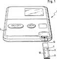
図1および2に示された分析システム1は、評価装置2および1回使用に定められた(使い捨ての)テストエレメント3からなる。
【0016】
該評価装置2は、テストエレメントホルダ5を有しており、該テストエレメントホルダを用いてテストエレメント3が図2に示された測定位置に位置付けられる。該テストエレメント3は、適当な手段、たとえば板ばね6によって前記測定位置で固定されている。
【0017】
測定の実施のために試料液体(たとえば血液)は、測定領域7内に置かれる。このことは、テストエレメント3の図示された実施態様の場合には、血液滴8がテストエレメント3の端に設けられた試料塗布領域9に塗布されかつそこから毛管間隙10中で測定領域7に吸引されることによって行なわれる。測定領域7中に試薬層12が存在しており、この試薬層は、試料液体によって溶解されかつ該試料液体の成分と反応する。
【0018】
該反応によって測定領域7内での測定可能な変化が導かれる。電気化学的なテストエレメントの図示された例では、電気的な測定量の測定は、測定領域内に備えられた、図に示されていない電極を用いて行なわれ、この電極は、接点ストリップ13と結合している。該接点ストリップ13は、前記測定位置で、テストエレメントホルダ5の相応する対接点14に電気的に接触し、この対接点は、測定−および評価電子機器15と結合している。できるだけコンパクトな構造および高い信頼性を考慮して測定および評価電子機器15は、高集積されている。図示された例では該測定および評価電子機器は、本質的に回路基板16および特定用途向けIC(ASIC)17からなる。
【0019】
該回路基板16に測定領域7の範囲内の温度の測定のための赤外線検出器20も取り付けられている。適当な赤外線検出器は、低費用で即利用可能なものである。有利に、自己補正のために組み込まれた温度センサ(たとえばNTC半導体素子)を包含する検出器型が選択される。
【0020】
赤外線検出器20が該測定および評価電子機器15の中に、該赤外線検出器20と該測定および評価電子機器15の残りの部品との間の固定された機械的な結合が存在する意味で組込まれている場合は、一般的に有利である。赤外線検出器20と測定−および評価電子機器15の残りの部品との間の機械的に固定された短い導線結合によってコンパクトな構造ばかりではなく、なかでも高い機械的かつ電子的な安定性ならびに良好な長期間の信頼性が達成される。
【0021】
この場合には、図2で破線で記入されている、赤外線を測定領域7から赤外線検出器20に戻さなければならない伝達路21が、比較的長くかつ直線ではないことは、先ず第一に欠点であると思われる。このことは、評価装置が実用において(簡単な取扱いを考慮して)所望される著しく平たい型式を有しておりかつそれゆえにテストエレメントホルダ5および電子機器ユニット15が相互に重ねて配置されることができない場合にとくに該当する。
【0022】
テストエレメントおよび評価装置のホルダが図示されているように、該テストエレメント3が前記測定位置で前記評価装置2の前記ケーシング23から突出する形で形成されている場合に、特別な付加的な問題が生じる。この構造は、本分析システムの取扱いにとって有利であり、それというのも、前記テストエレメントが前記測定位置に存在している間に、前記試料が前記測定領域7に置かれることができるからである。しかしながら、測定領域7の範囲内の温度の測定にとって、前記伝達路21がケーシング2に備えられた窓26を貫いて通っていてなければならず、かつケーシング23の外側を通っている部分21aを包含することは、欠点である。
【0023】
全体で22の符号がつけられた赤外線伝達手段によって、このように問題のある場合にも、測定領域7から出発する赤外線の選択的なおよび高感度の検出が可能となる。図示された例では赤外線伝達手段は、赤外線に対して反射性の内壁を有する導波管24および評価装置2のケーシング23内に配置された結像鏡25からなる。
【0024】
該導波管24は、少なくともその内面上が金属被覆された(とくに金めっきされた)プラスチック部材として実施されている。このような導波管24を用いて、簡単にかつ低費用でケーシング25内の赤外線のための所望される伝達路21が実施されることができる。
【0025】
−図示されたテストエレメント分析システムの場合のように−赤外線の伝達路21が評価装置2のケーシング25の外側を通っている部分21aをも有している限り、この部分で測定領域7から来る赤外線の必要な選択的な検出が光学結像系を用いて実施される場合が、有利であり、この場合、図2に示された凹面に曲げられた結像鏡25の使用が有利である。前記光学窓26は、有利に、赤外線に対して透過性の円板状物28、とくにポリエチレンフィルム、によって防塵形に閉じられている。
【0026】
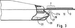
図3には別の実施態様示されており、この実施態様の場合には光学結像系は、円板状物28に組み込まれた光学レンズによって形成され、かつ、伝達路21上の赤外線の必要な光線誘導平面鏡29によって保証される。
【0027】
図2および3に示された実施態様の場合には位置選択的な光伝達手段22の機能は、充分に、結像鏡25またはレンズ27によって実施されている光学結像系の作用を基礎としている。導波管24の場合には主として、後方の、傾斜させた、平面鏡30として機能する面が効果的であり、この面によって赤外線検出器20への必要な誘導達成される。
【0028】
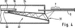
位置選択的な赤外線伝達手段の著しく効果的な、そしてしかも特に低費用の実施は、(光学結像系なしでも)内側が鏡面化された導波管24によって達成することができ、この導波管は、図4および5に示されているように−、その前記測定領域7側の入口31が前記赤外線検出器20側の出口32より大きな開口断面を有しているように形成されている。この場合には、導波管24が入口31と出口32の間で本質的に連続的に細くなっていく、すなわち、その断面が次第に小さくなっていく場合が有利である。このことによって、導波管24の壁で反射される赤外線の強度の集中が達成される。
【0029】
図4に示された実施態様の場合には導波管24の軸は、直線である。検出器20の感光性の面は、この場合には側面に存在している。しかしながら、導波管24を曲げられた形で、図5に示されているように、製造することも問題なく可能である。このような曲げられた形によって、検査領域7を有するテストエレメント3ならびに検出器20を備えた回路基板16の特に柔軟な形成および位置付けが可能となる。
【0030】
図4および5に光学結像系が示されていなくとも、自明のことながらこれらの図に示された型式の導波管24をレンズの形での、もしくは結像鏡の形での光学結像系と組み合わせることが可能である。
【図面の簡単な説明】
【図1】 本発明によるテストエレメント−分析システムを示す透視図である。
【図2】 本発明による分析システムを示す部分断面図である。
【図3】 別の実施態様を示す部分断面図である。
【図4】 もう1つ別の実施態様を示す断面概略図である。
【図5】 第3の別の実施態様を示す断面概略図である。[0001]
The present invention relates to a test element-analysis system for examination by analysis of samples, in particular human or animal body fluids. The system comprises two components: a test element having a measurement area in which the sample to be examined is placed for performing the analysis in order to measure a measurement characteristic for the analysis, and the test element. A test element holder for positioning at a measurement position for performing the measurement, and an evaluation apparatus including measurement and evaluation electronics for measuring the characteristic measurement amount and determining an analysis result based on the measurement amount included.
[0002]
Test element analysis systems are used in urine and blood analysis, especially in medicine. The test elements often have the form of test strips, however other forms of test elements are used, for example flat, approximately square platelets.
[0003]
Typically, a test element contains a reagent, and the reaction between the reagent and the sample causes a physically detectable change in the test element, which is measured by an evaluation device attached to the system. In particular, a photometric analysis system is used. In this analysis system, the reaction causes a color change in the detection layer of the test element, and this detection layer is photometrically measured. Furthermore, an electrochemical analysis system in which the reaction causes an electrochemical change in the test element that can be measured as a voltage or current is extremely important. In addition to analysis systems that operate with reagents, reagent-free analysis systems are also considered, in which case the analytical characteristics of the sample itself (for example, the sample itself) after contact between the test element and the sample. Optical absorption spectrum). The invention can be used in principle for all the above methods.
[0004]
In part, test element analysis systems are used in medical laboratories. However, the present invention is particularly directed to application cases where the analysis is performed by the patient himself (“home monitoring”) in order to continuously monitor the patient's health. This is particularly medically important for the treatment of diabetic patients whose insulin injections must be measured several times a day in order to adjust their insulin injection according to the concentration of glucose in the blood. For such purposes, the evaluation device must be light and small, battery-operated and robust.
[0005]
The basic problem is that the characteristic measurements for the analysis are often significantly temperature dependent. This temperature dependence is often 1-2 percent per degree. Within home monitoring, it is inevitable that the analytical system is subjected to significant temperature changes. There must be taken into account temperature fluctuations of at least ± 5 °, which essentially further if the measurement must be possible under unusual conditions (eg in the car or outdoors). High temperature fluctuations can occur.
[0006]
In order to avoid the measurement inaccuracies caused by this, it has been proposed to adjust the measuring area of the test element to a constant temperature determined by a corresponding temperature adjusting device. For example, US Pat. No. 5,035,862 describes the temperature adjustment of individual test fields of a urine test strip by induction heating. Another example of a blood analyzer is shown in German Offenlegungsschrift 3,321,783. However, this type of method is not feasible due to high energy consumption in the case of small battery powered devices.
[0007]
In the case of many analytical systems, the temperature is measured electrically (by thermocouple or thermal resistance) in the evaluation device casing during the measurement, and the temperature thus measured is used to determine the result of the analysis. To be taken into account. An example is shown in WO 99/06822. Such a correction is a temperature at which the temperature around the evaluation device and the test element has not changed for a relatively long time before the measurement, and for that reason the actual temperature of the sample at the measurement position is electrically measured. Can be accurate if it matches well. However, especially in the field of home monitoring, this condition is often not met because the patient's life situation requires the patient to perform the analysis at various locations and changing temperature conditions.
[0008]
In order to solve this problem, US Pat. No. 5,405,511 uses an extrapolation method in which the temperature is measured repeatedly at regular intervals, and the correction temperature is based on a temperature course measured over a certain time interval. It has been proposed to decide. This, however, requires that the temperature be measured continuously for several minutes or at regular intervals before analysis. In order to avoid the associated waiting time before the test is carried out, according to US Pat. No. 5,405,511, temperature measurements are carried out at intervals of several minutes even when the device is switched off. . This allows extrapolation to the corrected temperature to be performed immediately after the device is switched on. However, this method entails higher energy consumption since the device electronics must be started each time for temperature measurements at intervals of a few minutes. Moreover, the correction temperature calculation by the extrapolation algorithm is not reliable under all operating conditions.
[0009]
European Patent Application No. 08512229 describes an analysis system. In this analysis system, a temperature measuring surface is provided on the holder of the test element in the evaluation apparatus or on the test element itself. The temperature measuring surface is coated with thermochrome liquid crystal (TLC). The temperature of the TLC is determined by photometric measurement. A good agreement between this measurement and the actual temperature of the measurement area is achieved in this case only if the test element itself is coated with the TLC. However, this entails significant additional costs in the manufacture of the test element. Moreover, the acceptable accuracy of the temperature measurement can only be achieved with a high measurement technical expense.
[0010]
It is an object of the present invention to provide a test element analysis system that achieves increased measurement accuracy with improved temperature compensation. This test element analysis system should be possible at a low expense that is acceptable for a home monitoring system.
[0011]
This problem is solved in a test element analysis system of the kind described at the outset, wherein the evaluation device has an infrared detector for measuring the temperature within the measurement area of the test element. .
[0012]
The special requirements of a normal test strip analysis system are that the infrared detector directly detects the infrared rays coming from the measurement area sufficiently selectively and with high sensitivity to ensure the required accuracy of temperature measurement. In many cases, it is inevitable to position the infrared detector in such a manner. Within the scope of the present invention, for the solution of this problem, it is defined that the measurement area and the infrared detector are connected to each other by means of position-selective infrared transmission means, Meet the following requirements:
The infrared transmission means selectively supplies the detector with infrared radiation coming from the measurement area;
-A very high proportion of the infrared rays coming from the measurement area reach the detector, i.e. the transmission means function without loss.
[0013]
The above requirements can in principle be met by an optical imaging system having at least one lens. However, an essentially advantageous component of the infrared transmission means is a waveguide with an inner wall that is reflective to infrared, and / or an imaging mirror arranged in a casing, especially made of metal-coated plastic It is. These factors allow for almost no loss of infrared radiation from the measurement area to the infrared detector and at the same time a significantly better selectivity. In this case, the cost is small and it is possible without problems to implement a (non-linear) optical path between the measuring area and the infrared detector that is bent or polygonalized. is there. This makes it possible to carry out an infrared-temperature measurement in the measurement area optimized for the requirements of the test element analysis system.
[0014]
Next, the present invention will be described in detail with reference to the embodiments shown in the drawings. The features described in the embodiments can be used alone or in combination with each other to implement a preferred embodiment of the invention. The contents of the figure are as follows:
[0015]
The analysis system 1 shown in FIGS. 1 and 2 comprises an
[0016]
The
[0017]
In order to carry out the measurement, a sample liquid (eg blood) is placed in the
[0018]
The reaction leads to a measurable change in the
[0019]
An
[0020]
An
[0021]
In this case, first of all, it is a disadvantage that the
[0022]
As the test element and the holder of the evaluation device are illustrated, a special additional problem arises when the
[0023]
The infrared transmission means denoted by the
[0024]
The
[0025]
As in the case of the illustrated test element analysis system, as long as the
[0026]
FIG. 3 shows another embodiment, in which the optical imaging system is formed by an optical lens built into the
[0027]
In the case of the embodiment shown in FIGS. 2 and 3, the function of the position-selective light transmission means 22 is sufficiently based on the action of the optical imaging system implemented by the
[0028]
A remarkably effective and particularly low-cost implementation of a position-selective infrared transmission means can be achieved by a
[0029]
In the embodiment shown in FIG. 4, the axis of the
[0030]
Even if the optical imaging system is not shown in FIGS. 4 and 5, it is obvious that the
[Brief description of the drawings]
FIG. 1 is a perspective view of a test element-analysis system according to the present invention.
FIG. 2 is a partial sectional view showing an analysis system according to the present invention.
FIG. 3 is a partial cross-sectional view showing another embodiment.
FIG. 4 is a schematic cross-sectional view showing another embodiment.
FIG. 5 is a schematic cross-sectional view showing a third alternative embodiment.
Claims (2)
Translated fromJapanese前記試料(8)が前記測定領域(7)に置かれることができるように、前記テストエレメント(3)が前記測定位置で前記評価装置(2)の前記ケーシング(23)から、該テストエレメントが該測定位置に存在している間に、突出し、
該評価装置(2)が該テストエレメント(3)の該測定領域(7)の範囲内の温度の測定のために赤外線検出器(20)および前記測定領域(7)を前記赤外線検出器(20)と位置選択的に結合する赤外線伝達手段(22)とを有し、
前記検出器(20)が該ケーシング(22)中に位置付けられており、該ケーシング(23)が赤外線に対して透過性の光学窓(26)を有しており、かつ
該測定領域(7)と該赤外線検出器(20)の間の赤外線の伝達路(21)が該光学窓(26)を通して導かれる
ことを特徴とする分析システム。A test element analysis system (1) for testing by analyzing a sample of human or animal body fluid (8), wherein the sample to be tested is subjected to analysis in order to measure a characteristic quantity for the analysis. A test element (3) having a measurement area (7) placed for the test, as well as an evaluation device comprising a test element holder (5) for positioning the test element (3) in a measurement position for carrying out the measurement ( 2) and an analysis system including measurement and evaluation electronics (15) for measuring the characteristic measurement quantity and for determining an analysis result based on the measurement quantity,
The test element (3) is removed from the casing (23) of the evaluation device (2) at the measurement position so that the sample (8) can be placed in the measurement area (7). While present at the measurement position,
The evaluation device (2) uses the infrared detector (20)and the measurement region (7) to measure the temperature within the measurement region (7) of the test element (3).) And position-selective infrared transmission means (22),
The detector (20) is positioned in the casing (22), the casing (23) has an optical window (26) transparent to infrared; and
An analysis system, characterized in that aninfrared transmission path (21) between the measurement region (7) and the infrared detector (20) is guided through the optical window (26) .
Applications Claiming Priority (3)
| Application Number | Priority Date | Filing Date | Title |
|---|---|---|---|
| DE19952215.4 | 1999-10-29 | ||
| DE19952215ADE19952215C2 (en) | 1999-10-29 | 1999-10-29 | Test element analysis system |
| PCT/DE2000/003804WO2001033214A2 (en) | 1999-10-29 | 2000-10-26 | Test element analysis system with an infrared detector |
Publications (2)
| Publication Number | Publication Date |
|---|---|
| JP2003513277A JP2003513277A (en) | 2003-04-08 |
| JP3723772B2true JP3723772B2 (en) | 2005-12-07 |
Family
ID=7927361
Family Applications (1)
| Application Number | Title | Priority Date | Filing Date |
|---|---|---|---|
| JP2001535048AExpired - Fee RelatedJP3723772B2 (en) | 1999-10-29 | 2000-10-26 | Test element analysis system |
Country Status (7)
| Country | Link |
|---|---|
| US (1) | US6880968B1 (en) |
| EP (1) | EP1238274B1 (en) |
| JP (1) | JP3723772B2 (en) |
| AT (1) | ATE269542T1 (en) |
| CA (1) | CA2387728C (en) |
| DE (3) | DE19952215C2 (en) |
| WO (1) | WO2001033214A2 (en) |
Families Citing this family (89)
| Publication number | Priority date | Publication date | Assignee | Title |
|---|---|---|---|---|
| US6036924A (en) | 1997-12-04 | 2000-03-14 | Hewlett-Packard Company | Cassette of lancet cartridges for sampling blood |
| US6391005B1 (en) | 1998-03-30 | 2002-05-21 | Agilent Technologies, Inc. | Apparatus and method for penetration with shaft having a sensor for sensing penetration depth |
| DE10032015A1 (en)* | 2000-07-01 | 2002-01-10 | Roche Diagnostics Gmbh | Test strip analysis unit for bodily fluid, employs temperature history correction system which will not drain batteries |
| US8641644B2 (en) | 2000-11-21 | 2014-02-04 | Sanofi-Aventis Deutschland Gmbh | Blood testing apparatus having a rotatable cartridge with multiple lancing elements and testing means |
| DE10057832C1 (en) | 2000-11-21 | 2002-02-21 | Hartmann Paul Ag | Blood analysis device has syringe mounted in casing, annular mounting carrying needles mounted behind test strip and being swiveled so that needle can be pushed through strip and aperture in casing to take blood sample |
| US7041068B2 (en) | 2001-06-12 | 2006-05-09 | Pelikan Technologies, Inc. | Sampling module device and method |
| US8337419B2 (en) | 2002-04-19 | 2012-12-25 | Sanofi-Aventis Deutschland Gmbh | Tissue penetration device |
| US9795747B2 (en) | 2010-06-02 | 2017-10-24 | Sanofi-Aventis Deutschland Gmbh | Methods and apparatus for lancet actuation |
| JP4272051B2 (en) | 2001-06-12 | 2009-06-03 | ペリカン テクノロジーズ インコーポレイテッド | Blood sampling apparatus and method |
| US7344507B2 (en) | 2002-04-19 | 2008-03-18 | Pelikan Technologies, Inc. | Method and apparatus for lancet actuation |
| WO2002101359A2 (en) | 2001-06-12 | 2002-12-19 | Pelikan Technologies, Inc. | Integrated blood sampling analysis system with multi-use sampling module |
| US9226699B2 (en) | 2002-04-19 | 2016-01-05 | Sanofi-Aventis Deutschland Gmbh | Body fluid sampling module with a continuous compression tissue interface surface |
| EP1395185B1 (en) | 2001-06-12 | 2010-10-27 | Pelikan Technologies Inc. | Electric lancet actuator |
| JP4209767B2 (en) | 2001-06-12 | 2009-01-14 | ペリカン テクノロジーズ インコーポレイテッド | Self-optimized cutting instrument with adaptive means for temporary changes in skin properties |
| AU2002344825A1 (en) | 2001-06-12 | 2002-12-23 | Pelikan Technologies, Inc. | Method and apparatus for improving success rate of blood yield from a fingerstick |
| US7749174B2 (en) | 2001-06-12 | 2010-07-06 | Pelikan Technologies, Inc. | Method and apparatus for lancet launching device intergrated onto a blood-sampling cartridge |
| US9427532B2 (en) | 2001-06-12 | 2016-08-30 | Sanofi-Aventis Deutschland Gmbh | Tissue penetration device |
| US7981056B2 (en) | 2002-04-19 | 2011-07-19 | Pelikan Technologies, Inc. | Methods and apparatus for lancet actuation |
| US7344894B2 (en) | 2001-10-16 | 2008-03-18 | Agilent Technologies, Inc. | Thermal regulation of fluidic samples within a diagnostic cartridge |
| ITMI20012828A1 (en) | 2001-12-28 | 2003-06-28 | Gambro Dasco Spa | NON-INVASIVE DEVICE FOR THE DETECTION OF BLOOD TEMPERATURE IN A CIRCUIT FOR THE EXTRACORPOREAL BLOOD CIRCULATION AND APPARATUS |
| JP4505837B2 (en)* | 2002-01-18 | 2010-07-21 | アークレイ株式会社 | Analyzing device with temperature detector |
| US7229458B2 (en) | 2002-04-19 | 2007-06-12 | Pelikan Technologies, Inc. | Method and apparatus for penetrating tissue |
| US7291117B2 (en) | 2002-04-19 | 2007-11-06 | Pelikan Technologies, Inc. | Method and apparatus for penetrating tissue |
| US7717863B2 (en) | 2002-04-19 | 2010-05-18 | Pelikan Technologies, Inc. | Method and apparatus for penetrating tissue |
| US7547287B2 (en) | 2002-04-19 | 2009-06-16 | Pelikan Technologies, Inc. | Method and apparatus for penetrating tissue |
| US7491178B2 (en) | 2002-04-19 | 2009-02-17 | Pelikan Technologies, Inc. | Method and apparatus for penetrating tissue |
| US7524293B2 (en) | 2002-04-19 | 2009-04-28 | Pelikan Technologies, Inc. | Method and apparatus for penetrating tissue |
| US7563232B2 (en) | 2002-04-19 | 2009-07-21 | Pelikan Technologies, Inc. | Method and apparatus for penetrating tissue |
| US8221334B2 (en) | 2002-04-19 | 2012-07-17 | Sanofi-Aventis Deutschland Gmbh | Method and apparatus for penetrating tissue |
| US7648468B2 (en) | 2002-04-19 | 2010-01-19 | Pelikon Technologies, Inc. | Method and apparatus for penetrating tissue |
| US9314194B2 (en) | 2002-04-19 | 2016-04-19 | Sanofi-Aventis Deutschland Gmbh | Tissue penetration device |
| US8579831B2 (en) | 2002-04-19 | 2013-11-12 | Sanofi-Aventis Deutschland Gmbh | Method and apparatus for penetrating tissue |
| US7331931B2 (en) | 2002-04-19 | 2008-02-19 | Pelikan Technologies, Inc. | Method and apparatus for penetrating tissue |
| US7297122B2 (en) | 2002-04-19 | 2007-11-20 | Pelikan Technologies, Inc. | Method and apparatus for penetrating tissue |
| US7410468B2 (en) | 2002-04-19 | 2008-08-12 | Pelikan Technologies, Inc. | Method and apparatus for penetrating tissue |
| US8784335B2 (en) | 2002-04-19 | 2014-07-22 | Sanofi-Aventis Deutschland Gmbh | Body fluid sampling device with a capacitive sensor |
| US9248267B2 (en) | 2002-04-19 | 2016-02-02 | Sanofi-Aventis Deustchland Gmbh | Tissue penetration device |
| US7674232B2 (en) | 2002-04-19 | 2010-03-09 | Pelikan Technologies, Inc. | Method and apparatus for penetrating tissue |
| US7708701B2 (en) | 2002-04-19 | 2010-05-04 | Pelikan Technologies, Inc. | Method and apparatus for a multi-use body fluid sampling device |
| US8267870B2 (en) | 2002-04-19 | 2012-09-18 | Sanofi-Aventis Deutschland Gmbh | Method and apparatus for body fluid sampling with hybrid actuation |
| US7909778B2 (en) | 2002-04-19 | 2011-03-22 | Pelikan Technologies, Inc. | Method and apparatus for penetrating tissue |
| US7481776B2 (en) | 2002-04-19 | 2009-01-27 | Pelikan Technologies, Inc. | Method and apparatus for penetrating tissue |
| US7371247B2 (en) | 2002-04-19 | 2008-05-13 | Pelikan Technologies, Inc | Method and apparatus for penetrating tissue |
| US8702624B2 (en) | 2006-09-29 | 2014-04-22 | Sanofi-Aventis Deutschland Gmbh | Analyte measurement device with a single shot actuator |
| US7976476B2 (en) | 2002-04-19 | 2011-07-12 | Pelikan Technologies, Inc. | Device and method for variable speed lancet |
| US9795334B2 (en) | 2002-04-19 | 2017-10-24 | Sanofi-Aventis Deutschland Gmbh | Method and apparatus for penetrating tissue |
| US7232451B2 (en) | 2002-04-19 | 2007-06-19 | Pelikan Technologies, Inc. | Method and apparatus for penetrating tissue |
| US7141058B2 (en) | 2002-04-19 | 2006-11-28 | Pelikan Technologies, Inc. | Method and apparatus for a body fluid sampling device using illumination |
| US7901362B2 (en) | 2002-04-19 | 2011-03-08 | Pelikan Technologies, Inc. | Method and apparatus for penetrating tissue |
| US7374544B2 (en) | 2002-04-19 | 2008-05-20 | Pelikan Technologies, Inc. | Method and apparatus for penetrating tissue |
| US7892183B2 (en) | 2002-04-19 | 2011-02-22 | Pelikan Technologies, Inc. | Method and apparatus for body fluid sampling and analyte sensing |
| US7582099B2 (en) | 2002-04-19 | 2009-09-01 | Pelikan Technologies, Inc | Method and apparatus for penetrating tissue |
| SE523545C2 (en)* | 2002-09-19 | 2004-04-27 | Foss Tecator Ab | Method, a portable device and a measuring instrument for standardizing a satellite measuring instrument to a corresponding main measuring instrument |
| DE10253934C1 (en)* | 2002-11-19 | 2003-12-04 | Seleon Gmbh | Continuous positive airway pressure respiration device with selective illumination of display and/or operating controls under control of sensor signal |
| US8574895B2 (en) | 2002-12-30 | 2013-11-05 | Sanofi-Aventis Deutschland Gmbh | Method and apparatus using optical techniques to measure analyte levels |
| EP1443325A1 (en)* | 2003-02-01 | 2004-08-04 | Roche Diagnostics GmbH | System and method for determining a coagulation parameter |
| US7850621B2 (en) | 2003-06-06 | 2010-12-14 | Pelikan Technologies, Inc. | Method and apparatus for body fluid sampling and analyte sensing |
| WO2006001797A1 (en) | 2004-06-14 | 2006-01-05 | Pelikan Technologies, Inc. | Low pain penetrating |
| EP1635700B1 (en) | 2003-06-13 | 2016-03-09 | Sanofi-Aventis Deutschland GmbH | Apparatus for a point of care device |
| US8282576B2 (en) | 2003-09-29 | 2012-10-09 | Sanofi-Aventis Deutschland Gmbh | Method and apparatus for an improved sample capture device |
| EP1680014A4 (en) | 2003-10-14 | 2009-01-21 | Pelikan Technologies Inc | METHOD AND DEVICE FOR A VARIABLE USER INTERFACE |
| US7444005B2 (en)* | 2003-11-04 | 2008-10-28 | Becton, Dickinson And Company | Apparatus and method for using optical mouse engine to determine speed, direction, position of scanned device and to obtain quantitative or qualitative data from same |
| US8668656B2 (en) | 2003-12-31 | 2014-03-11 | Sanofi-Aventis Deutschland Gmbh | Method and apparatus for improving fluidic flow and sample capture |
| US7822454B1 (en) | 2005-01-03 | 2010-10-26 | Pelikan Technologies, Inc. | Fluid sampling device with improved analyte detecting member configuration |
| US20050227370A1 (en)* | 2004-03-08 | 2005-10-13 | Ramel Urs A | Body fluid analyte meter & cartridge system for performing combined general chemical and specific binding assays |
| WO2006011062A2 (en) | 2004-05-20 | 2006-02-02 | Albatros Technologies Gmbh & Co. Kg | Printable hydrogel for biosensors |
| WO2005120365A1 (en) | 2004-06-03 | 2005-12-22 | Pelikan Technologies, Inc. | Method and apparatus for a fluid sampling device |
| JP4742184B2 (en)* | 2004-09-30 | 2011-08-10 | アークレイ株式会社 | Analysis equipment |
| WO2006070199A1 (en)* | 2004-12-29 | 2006-07-06 | Lifescan Scotland Limited | An analyte test meter having a test sensor port |
| US8652831B2 (en) | 2004-12-30 | 2014-02-18 | Sanofi-Aventis Deutschland Gmbh | Method and apparatus for analyte measurement test time |
| EP1813937A1 (en)* | 2006-01-25 | 2007-08-01 | Roche Diagnostics GmbH | Electrochemical biosensor analysis system |
| US7947222B2 (en)* | 2006-08-15 | 2011-05-24 | Infopia Co., Ltd. | Mobile communication terminal equipped with temperature compensation function for use in bio-information measurement |
| EP1889568A1 (en) | 2006-08-16 | 2008-02-20 | Infopia Co., Ltd. | Mobile communication terminal equipped with temperature compensation function for use in bioinformation measurement |
| ES2693097T3 (en) | 2007-05-30 | 2018-12-07 | Ascensia Diabetes Care Holdings Ag | System and method for managing health data |
| JP5773241B2 (en)* | 2007-10-15 | 2015-09-02 | バイエル・ヘルスケア・エルエルシーBayer HealthCareLLC | Method and assembly for determining the temperature of a test sensor |
| EP2265324B1 (en) | 2008-04-11 | 2015-01-28 | Sanofi-Aventis Deutschland GmbH | Integrated analyte measurement system |
| CN102575963B (en)* | 2008-10-21 | 2014-07-16 | 生命扫描有限公司 | Multiple temperature measurements coupled with modeling |
| US20100130838A1 (en)* | 2008-10-21 | 2010-05-27 | Kermani Mahyar Z | Infrared Temperature Measurement of Strip |
| EP2851676B1 (en)* | 2008-12-18 | 2016-12-28 | Ascensia Diabetes Care Holdings AG | Test sensor with grating for determining the temperature of the sensor |
| US9375169B2 (en) | 2009-01-30 | 2016-06-28 | Sanofi-Aventis Deutschland Gmbh | Cam drive for managing disposable penetrating member actions with a single motor and motor and control system |
| EP2408931A2 (en)* | 2009-03-20 | 2012-01-25 | Roche Diagnostics GmbH | Test element for determining a body fluid and measurement method |
| US8801273B2 (en)* | 2009-06-08 | 2014-08-12 | Bayer Healthcare Llc | Method and assembly for determining the temperature of a test sensor |
| JP5270501B2 (en)* | 2009-09-17 | 2013-08-21 | テルモ株式会社 | Blood glucose meter and blood glucose level measuring method |
| US9326708B2 (en)* | 2010-03-26 | 2016-05-03 | Medtronic Minimed, Inc. | Ambient temperature sensor systems and methods |
| US8965476B2 (en) | 2010-04-16 | 2015-02-24 | Sanofi-Aventis Deutschland Gmbh | Tissue penetration device |
| US8275413B1 (en)* | 2011-09-17 | 2012-09-25 | Fraden Corp. | Wireless communication device with integrated electromagnetic radiation sensors |
| JP5749806B2 (en)* | 2011-11-01 | 2015-07-15 | パナソニックヘルスケアホールディングス株式会社 | Biological sample measuring device |
| WO2015141510A1 (en)* | 2014-03-20 | 2015-09-24 | パナソニックヘルスケアホールディングス株式会社 | Biological information measurement device and method for controlling biological information measurement device |
| US20180095049A1 (en)* | 2016-09-30 | 2018-04-05 | Lifescan Scotland Limited | Hand-held test meter with analytical test strip contact pressure feature |
Family Cites Families (48)
| Publication number | Priority date | Publication date | Assignee | Title |
|---|---|---|---|---|
| US4360723A (en)* | 1979-10-31 | 1982-11-23 | Tokyo Shibaura Denki Kabushiki Kaisha | Microwave oven |
| CA1168064A (en) | 1980-03-22 | 1984-05-29 | Klaus Nenninger | Device for positioning a test strip for optical- medical measurements |
| DE3011223C2 (en) | 1980-03-22 | 1983-04-14 | Clinicon Mannheim GmbH, 6800 Mannheim | Device for positioning and holding a test strip for optical medical measurements |
| DE3321783A1 (en)* | 1983-06-16 | 1984-12-20 | Boehringer Mannheim Gmbh, 6800 Mannheim | ARRANGEMENT FOR EVALUATING A TEST STRIP |
| DE3742786A1 (en) | 1987-12-17 | 1989-06-29 | Boehringer Mannheim Gmbh | ANALYSIS SYSTEM FOR DETERMINING A COMPONENT OF A LIQUID |
| US4947850A (en)* | 1988-03-11 | 1990-08-14 | Trustees Of The University Of Pennsylvania | Method and apparatus for imaging an internal body portion of a host animal |
| US4993419A (en)* | 1988-12-06 | 1991-02-19 | Exergen Corporation | Radiation detector suitable for tympanic temperature measurement |
| US4988211A (en)* | 1989-04-27 | 1991-01-29 | The Dow Chemical Company | Process and apparatus for contactless measurement of sample temperature |
| US5095913A (en)* | 1989-09-01 | 1992-03-17 | Critikon, Inc. | Shutterless optically stabilized capnograph |
| US5578499A (en) | 1989-09-20 | 1996-11-26 | The Royal Institution For The Advancement Of Learning | Homogeneous immunoassay system employing fourier transform infrared spectroscopy |
| US5313941A (en)* | 1993-01-28 | 1994-05-24 | Braig James R | Noninvasive pulsed infrared spectrophotometer |
| US5405511A (en)* | 1993-06-08 | 1995-04-11 | Boehringer Mannheim Corporation | Biosensing meter with ambient temperature estimation method and system |
| WO1995022928A1 (en)* | 1994-02-28 | 1995-08-31 | Economation, Inc. | Infrared tympanic thermometer |
| US5626139A (en)* | 1994-09-23 | 1997-05-06 | Artech Industries, Inc. | Tympanic thermometer |
| US5695949A (en)* | 1995-04-07 | 1997-12-09 | Lxn Corp. | Combined assay for current glucose level and intermediate or long-term glycemic control |
| EP0801926A4 (en) | 1995-11-13 | 1999-05-26 | Citizen Watch Co Ltd | RADIATION MEDICAL THERMOMETER |
| US5820264A (en) | 1996-03-25 | 1998-10-13 | Oriental System Technology, Inc. | Tympanic thermometer arrangement |
| JPH10142066A (en) | 1996-11-06 | 1998-05-29 | Nikon Corp | Observation device |
| JP3368159B2 (en)* | 1996-11-20 | 2003-01-20 | 東京エレクトロン株式会社 | Plasma processing equipment |
| US5972715A (en) | 1996-12-23 | 1999-10-26 | Bayer Corporation | Use of thermochromic liquid crystals in reflectometry based diagnostic methods |
| JPH10227699A (en) | 1997-02-14 | 1998-08-25 | Matsushita Electric Ind Co Ltd | Non-contact temperature sensor |
| US5823966A (en)* | 1997-05-20 | 1998-10-20 | Buchert; Janusz Michal | Non-invasive continuous blood glucose monitoring |
| US5985675A (en)* | 1997-12-31 | 1999-11-16 | Charm Sciences, Inc. | Test device for detection of an analyte |
| US6066243A (en)* | 1997-07-22 | 2000-05-23 | Diametrics Medical, Inc. | Portable immediate response medical analyzer having multiple testing modules |
| DE19733445A1 (en)* | 1997-08-02 | 1999-02-18 | Boehringer Mannheim Gmbh | Analysis appts. with time counter and data processor for blood glucose level monitoring |
| JP3203411B2 (en)* | 1997-08-04 | 2001-08-27 | アークレイ株式会社 | Clinical testing device and method |
| NZ524206A (en)* | 1997-12-04 | 2004-05-28 | Roche Diagnostics Corp | Instrument for determining the concentration of a medically significant component of a sample |
| DE19810163A1 (en) | 1998-03-05 | 1999-09-30 | Valco Cincinnati Gmbh | Device for the detection of water and water-containing substances, in particular water-containing adhesives, on surfaces of any materials |
| US6302855B1 (en)* | 1998-05-20 | 2001-10-16 | Novo Nordisk A/S | Medical apparatus for use by a patient for medical self treatment of diabetes |
| US6201245B1 (en)* | 1998-06-18 | 2001-03-13 | Robert J. Schrader | Infrared, multiple gas analyzer and methods for gas analysis |
| US6518034B1 (en)* | 1998-06-25 | 2003-02-11 | Abb Diagnostics, Ltd. | Test strip for blood glucose determination |
| US6084660A (en)* | 1998-07-20 | 2000-07-04 | Lifescan, Inc. | Initiation of an analytical measurement in blood |
| US6261519B1 (en)* | 1998-07-20 | 2001-07-17 | Lifescan, Inc. | Medical diagnostic device with enough-sample indicator |
| US6087182A (en)* | 1998-08-27 | 2000-07-11 | Abbott Laboratories | Reagentless analysis of biological samples |
| US6424851B1 (en)* | 1998-10-13 | 2002-07-23 | Medoptix, Inc. | Infrared ATR glucose measurement system (II) |
| US6136610A (en)* | 1998-11-23 | 2000-10-24 | Praxsys Biosystems, Inc. | Method and apparatus for performing a lateral flow assay |
| US6167290A (en)* | 1999-02-03 | 2000-12-26 | Bayspec, Inc. | Method and apparatus of non-invasive measurement of human/animal blood glucose and other metabolites |
| EP1194069B1 (en)* | 1999-07-08 | 2006-03-22 | Steffen Dr.-Ing. Leonhardt | Device for measuring the blood-sugar level in humans |
| US6133552A (en)* | 1999-08-11 | 2000-10-17 | General Electric Company | Sensor assembly for glass-ceramic cooktop appliance and method of calibrating |
| US6320170B1 (en)* | 1999-09-17 | 2001-11-20 | Cem Corporation | Microwave volatiles analyzer with high efficiency cavity |
| US20020048307A1 (en)* | 2000-09-14 | 2002-04-25 | Volker Schmidt | Device and process for infrared temperature measurement |
| US6541266B2 (en)* | 2001-02-28 | 2003-04-01 | Home Diagnostics, Inc. | Method for determining concentration of an analyte in a test strip |
| US6898451B2 (en)* | 2001-03-21 | 2005-05-24 | Minformed, L.L.C. | Non-invasive blood analyte measuring system and method utilizing optical absorption |
| EP1397068A2 (en)* | 2001-04-02 | 2004-03-17 | Therasense, Inc. | Blood glucose tracking apparatus and methods |
| US20040147034A1 (en)* | 2001-08-14 | 2004-07-29 | Gore Jay Prabhakar | Method and apparatus for measuring a substance in a biological sample |
| US6678542B2 (en)* | 2001-08-16 | 2004-01-13 | Optiscan Biomedical Corp. | Calibrator configured for use with noninvasive analyte-concentration monitor and employing traditional measurements |
| US7364551B2 (en)* | 2001-11-09 | 2008-04-29 | Kamata, Llc | Hand-held medical apparatus |
| US7811231B2 (en)* | 2002-12-31 | 2010-10-12 | Abbott Diabetes Care Inc. | Continuous glucose monitoring system and methods of use |
- 1999
- 1999-10-29DEDE19952215Apatent/DE19952215C2/ennot_activeExpired - Fee Related
- 2000
- 2000-10-26JPJP2001535048Apatent/JP3723772B2/ennot_activeExpired - Fee Related
- 2000-10-26USUS10/111,626patent/US6880968B1/ennot_activeExpired - Lifetime
- 2000-10-26DEDE50006851Tpatent/DE50006851D1/ennot_activeExpired - Lifetime
- 2000-10-26WOPCT/DE2000/003804patent/WO2001033214A2/enactiveIP Right Grant
- 2000-10-26EPEP00984870Apatent/EP1238274B1/ennot_activeExpired - Lifetime
- 2000-10-26DEDE10083447Tpatent/DE10083447D2/ennot_activeExpired - Fee Related
- 2000-10-26ATAT00984870Tpatent/ATE269542T1/ennot_activeIP Right Cessation
- 2000-10-26CACA002387728Apatent/CA2387728C/ennot_activeExpired - Fee Related
Also Published As
| Publication number | Publication date |
|---|---|
| EP1238274B1 (en) | 2004-06-16 |
| US6880968B1 (en) | 2005-04-19 |
| WO2001033214A3 (en) | 2001-11-15 |
| WO2001033214A2 (en) | 2001-05-10 |
| DE10083447D2 (en) | 2002-12-05 |
| EP1238274A2 (en) | 2002-09-11 |
| DE19952215C2 (en) | 2001-10-31 |
| ATE269542T1 (en) | 2004-07-15 |
| CA2387728A1 (en) | 2001-05-10 |
| DE50006851D1 (en) | 2004-07-22 |
| DE19952215A1 (en) | 2001-05-17 |
| JP2003513277A (en) | 2003-04-08 |
| CA2387728C (en) | 2009-01-06 |
Similar Documents
| Publication | Publication Date | Title |
|---|---|---|
| JP3723772B2 (en) | Test element analysis system | |
| EP0619880B1 (en) | Improved non-invasive near-infrared quantitative measurement instrument | |
| AU674474B2 (en) | An analytical system for monitoring a substance to be analyzed in patient-blood | |
| ES2252735T3 (en) | PERCEPTOR OF FLOW DOSE AND COAGULATION OF A FLUID FOR A MEDICAL INSTRUMENT. | |
| JP3686422B2 (en) | Measurement of tissue analyte by infrared rays | |
| JP3337670B2 (en) | Specimen for analyzing body fluid samples and reading with a detector | |
| JP7729629B2 (en) | Disposable indicator components for measuring analyte concentrations in body fluids - Patent Application 20070122999 | |
| EA002288B1 (en) | Non-invasive continuous blood glucose monitoring | |
| AU2003282351A1 (en) | Photometric determination of coagulation time in undiluted whole blood | |
| JP2012506536A (en) | Infrared temperature measurement of strip | |
| US11662304B2 (en) | System and method for in situ measuring and collecting samples of analyte concentration in bodily fluids | |
| US20140273270A1 (en) | Direct temperature measurement of a test strip | |
| WO1999035487A1 (en) | Methods and apparatus for accurate analysis of bodily fluid constituents | |
| US20040010185A1 (en) | Method for measuring a physiologic parameter using a preferred site | |
| US20030077205A1 (en) | Diagnostic test optical fiber tips | |
| RU2830152C1 (en) | Disposable indicator component for measuring concentration of analyte in biological fluids | |
| RU2051383C1 (en) | Device for determining blood coagulation time |
Legal Events
| Date | Code | Title | Description |
|---|---|---|---|
| A131 | Notification of reasons for refusal | Free format text:JAPANESE INTERMEDIATE CODE: A131 Effective date:20040615 | |
| A601 | Written request for extension of time | Free format text:JAPANESE INTERMEDIATE CODE: A601 Effective date:20040915 | |
| A602 | Written permission of extension of time | Free format text:JAPANESE INTERMEDIATE CODE: A602 Effective date:20040929 | |
| A521 | Request for written amendment filed | Free format text:JAPANESE INTERMEDIATE CODE: A523 Effective date:20041214 | |
| A02 | Decision of refusal | Free format text:JAPANESE INTERMEDIATE CODE: A02 Effective date:20050222 | |
| A521 | Request for written amendment filed | Free format text:JAPANESE INTERMEDIATE CODE: A523 Effective date:20050520 | |
| A911 | Transfer to examiner for re-examination before appeal (zenchi) | Free format text:JAPANESE INTERMEDIATE CODE: A911 Effective date:20050809 | |
| TRDD | Decision of grant or rejection written | ||
| A01 | Written decision to grant a patent or to grant a registration (utility model) | Free format text:JAPANESE INTERMEDIATE CODE: A01 Effective date:20050830 | |
| A61 | First payment of annual fees (during grant procedure) | Free format text:JAPANESE INTERMEDIATE CODE: A61 Effective date:20050916 | |
| R150 | Certificate of patent or registration of utility model | Free format text:JAPANESE INTERMEDIATE CODE: R150 | |
| FPAY | Renewal fee payment (event date is renewal date of database) | Free format text:PAYMENT UNTIL: 20090922 Year of fee payment:4 | |
| FPAY | Renewal fee payment (event date is renewal date of database) | Free format text:PAYMENT UNTIL: 20100922 Year of fee payment:5 | |
| FPAY | Renewal fee payment (event date is renewal date of database) | Free format text:PAYMENT UNTIL: 20110922 Year of fee payment:6 | |
| FPAY | Renewal fee payment (event date is renewal date of database) | Free format text:PAYMENT UNTIL: 20120922 Year of fee payment:7 | |
| FPAY | Renewal fee payment (event date is renewal date of database) | Free format text:PAYMENT UNTIL: 20130922 Year of fee payment:8 | |
| R250 | Receipt of annual fees | Free format text:JAPANESE INTERMEDIATE CODE: R250 | |
| R250 | Receipt of annual fees | Free format text:JAPANESE INTERMEDIATE CODE: R250 | |
| R250 | Receipt of annual fees | Free format text:JAPANESE INTERMEDIATE CODE: R250 | |
| R250 | Receipt of annual fees | Free format text:JAPANESE INTERMEDIATE CODE: R250 | |
| LAPS | Cancellation because of no payment of annual fees |