JP3722064B2 - communication cable - Google Patents
communication cableDownload PDFInfo
- Publication number
- JP3722064B2 JP3722064B2JP2002012991AJP2002012991AJP3722064B2JP 3722064 B2JP3722064 B2JP 3722064B2JP 2002012991 AJP2002012991 AJP 2002012991AJP 2002012991 AJP2002012991 AJP 2002012991AJP 3722064 B2JP3722064 B2JP 3722064B2
- Authority
- JP
- Japan
- Prior art keywords
- interposition
- communication cable
- central axis
- twisted wires
- wires
- Prior art date
- Legal status (The legal status is an assumption and is not a legal conclusion. Google has not performed a legal analysis and makes no representation as to the accuracy of the status listed.)
- Expired - Fee Related
Links
- 230000008878couplingEffects0.000description7
- 238000010168coupling processMethods0.000description7
- 238000005859coupling reactionMethods0.000description7
- 230000004048modificationEffects0.000description4
- 238000012986modificationMethods0.000description4
- 230000000694effectsEffects0.000description3
- 239000004698PolyethyleneSubstances0.000description2
- 230000008901benefitEffects0.000description2
- 230000005540biological transmissionEffects0.000description2
- 230000015572biosynthetic processEffects0.000description2
- -1polyethylenePolymers0.000description2
- 229920000573polyethylenePolymers0.000description2
- 230000009467reductionEffects0.000description2
- 239000011347resinSubstances0.000description2
- 229920005989resinPolymers0.000description2
- 239000011248coating agentSubstances0.000description1
- 238000000576coating methodMethods0.000description1
- 239000004020conductorSubstances0.000description1
- 238000007765extrusion coatingMethods0.000description1
- 230000006872improvementEffects0.000description1
- 230000002093peripheral effectEffects0.000description1
- 239000007787solidSubstances0.000description1
- 239000000126substanceSubstances0.000description1
Images


Classifications
- H—ELECTRICITY
- H01—ELECTRIC ELEMENTS
- H01B—CABLES; CONDUCTORS; INSULATORS; SELECTION OF MATERIALS FOR THEIR CONDUCTIVE, INSULATING OR DIELECTRIC PROPERTIES
- H01B11/00—Communication cables or conductors
- H01B11/02—Cables with twisted pairs or quads
- H01B11/04—Cables with twisted pairs or quads with pairs or quads mutually positioned to reduce cross-talk
Landscapes
- Insulated Conductors (AREA)
Description
Translated fromJapanese【0001】
【発明の属する技術分野】
この発明は、LANなどに使用される通信ケーブルに関する。
【0002】
【従来の技術】
複数の対撚り線(ツイストペアともいう)を備えた通信ケーブルにおいて、各対撚り線間の静電結合に起因する漏話特性は、対撚り線間の距離及び各対撚り線間に介在する物質の誘電率により影響される。
【0003】
一般的には、対撚り線間に断面略十字状の介在芯を介在させて、各対撚り線間の距離を確保し、各対撚り線同士の漏話特性を向上させるようにしている。
【0004】
この種の通信ケーブルとして、例えば、特開平11−283449号公報に開示のものがある。
【0005】
【発明が解決しようとする課題】
しかしながら、上述のような通信ケーブルにおいて、各対撚り線間に介在する介在芯の誘電率は空気の誘電率よりも比較的大きい。例えば、介在芯は一般的にポリエチレンにより形成されるところ、ポリエチレンの誘電率εは2.3程度であり、空気の誘電率(εはほぼ1)よりも大きい。このため、静電結合に起因する漏話特性の改善効果が不十分となってしまう。
【0006】
そこで、この発明の課題は、漏話特性をより向上させることができる通信ケーブルを提供することにある。
【0007】
【課題を解決するための手段】
上記課題を解決すべく、請求項1記載の通信ケーブルは、一対の絶縁心線を撚り合わせてなる複数本の対撚り線と、前記各対撚り線を相互に隔てる複数の介在片が中心軸から放射状に延設された断面略放射状の介在芯と、を備え、前記各介在片のうち隣合う前記各対撚り線間に介在して当該各対撚り線に接触する部分よりも、前記中心軸側の部分、又は、前記中心軸側の部分及び先端側の部分の双方が薄肉に形成されたものである。
【0008】
請求項2記載のように、前記各介在片のうち隣合う前記各対撚り線間に介在して当該各対撚り線に接触する部分よりも中心軸側の部分がその中心軸側に向うに従って順次薄肉に形成されていてもよい。
【0009】
また、請求項3記載のように、前記各介在片のうち前記各対撚り線間に介在して当該各対撚り線に接触する部分だけを厚肉に形成し、その他の部分を一様に薄肉に形成してもよい。
【0010】
さらに、請求項4記載のように、前記各介在片のうちの少なくとも一部が中空に形成されていてもよい。
【0012】
【発明の実施の形態】
{第1の実施の形態}
以下、この発明の第1の実施の形態に係る通信ケーブルについて説明する。
【0013】
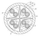
この通信ケーブルは、図1に示すように、複数本(ここでは4本)の対撚り線2と、介在芯10とを備えており、これら対撚り線2及び介在芯10が外皮8により被覆された構成とされている。この通信ケーブルは、例えばカテゴリ6に規定されるLAN用の高速伝送用ケーブルとして使用される。
【0014】
各対撚り線2は、導体3の外周囲に樹脂等による被覆部4を被覆した絶縁心線5を、2本撚り合わせることにより形成されている。これら複数の対撚り線2は所定の中心軸(通信ケーブルの中心軸)周りに集合配置される。
【0015】
介在芯10は、複数の介在片11が所定の中心軸から放射状に延設されており、断面略放射状の長尺形状を有している。本実施の形態では、介在芯10は断面略十字状の長尺形状を有している。
【0016】
上記各介在片11は、前記中心軸周りで隣合う各対撚り線2間に介在して当該隣合う各対撚り線2間の距離を一定以上に保つ機能を有している。
【0017】
本実施の形態では、4本の対撚り線2が所定の中心軸周りに集合配置されているので、4枚の介在片11が前記中心軸から放射状に延設されて、介在芯10の断面形状が略十字状に形成されている。なお、介在片11の数及び介在芯10の放射状断面形状は、対撚り線2の数に応じて適宜変更される。
【0018】
また、上記介在片11のうち隣合う各対撚り線2間に介在して当該各対撚り線2に接触する部分11aを除く部分の少なくとも一部が、その部分11aよりも薄肉に形成されている。
【0019】
なお、ここで、隣り合う各対撚り線2とは、前記中心軸周りで隣り合う各対撚り線2の関係をいい、中心軸を挟んで対向する関係(例えば図1の右上の対撚り線2と左下の対撚り線2との関係)を含まない。
【0020】
本実施の形態では、各介在片11の幅方向中間部の接触介在部11a、即ち、中心軸側部分と先端側の部分(図1では外皮8の内周部に接触又は近い部分)との中間部の接触介在部11aが隣合う対撚り線2間に介在して当該各対撚り線2に接触している。そして、隣合う対撚り線2間の距離が、当該介在片11の接触介在部11aの厚み寸法分以上に保たれるようになっている。
【0021】
そして、各介在片11のうち前記接触介在部11aよりも先端側の部分が、その先端部に向うに従って順次薄肉に形成されると共に、各介在片11のうち接触介在部11aよりも中心軸側の部分がその中心軸側に向うに従って順次薄肉に形成されている。このように各介在片11の接触介在部11aを除く部分を薄肉に形成した空間部分には、比較的誘電率の小さな空気が介在している。
【0022】
また、外皮8は、樹脂の押出被覆等により、所定厚み寸法を有する管状に形成されている。
【0023】
このように構成された通信ケーブルによると、各介在片11の接触介在部11aは比較的厚肉に形成されているため、隣合う対撚り線2間の距離を、当該介在片11の接触介在部11aの厚み寸法分以上に保つことができる。同時に、各介在片11のうち前記接触介在部11aを除く部分の少なくとも一部を、当該接触介在部11aよりも薄肉に形成しているため、その部分を薄肉に形成していない場合と比べて、各対撚り線2間に介在する、比較的誘電率の小さな空気の占有率を大きくできる。従って、静電結合に起因する漏話特性をより向上させることができる。
【0024】
なお、各介在片11のうち接触介在部11aを除く部分を薄肉にする形状は、上記した態様に限られない。例えば、各介在片11のうち接触介在部11aよりも先端側の部分又は中心軸側の部分だけを、順次薄肉に形成するようにしてもよい。
【0025】
また、図2に示す変形例の介在芯10Bのように、各介在片11Bの接触介在部11Ba(上記接触介在部11aに対応する部分)だけを厚肉に形成し、その他の部分を一様に薄肉に形成してもよい。この場合、各介在片11Bのうち接触介在部11Baよりも中心軸側の部分だけを一様に薄肉に形成してもよい。
【0027】
なお、この通信ケーブルでは、上述のようにして漏話特性を向上させることができるので、各対撚り線2間の距離を比較的小さくして、その外径を小さくすることができる。このように通信ケーブルの外径を小さくすることができるので、例えば、通信ケーブルの外径が太くなり過ぎて端末コネクタ加工等に不具合を生じるといった問題をも解消できる。また、同様の理由により、介在芯10,10B等のコンパクト化も可能となるので、コストダウンにもつながる。
【0028】
{第2の実施の形態}
次に、この発明の第2の実施の形態に係る通信ケーブルについて説明する。
【0029】
この通信ケーブルは、図3に示すように、複数本(ここでは4本)の対撚り線2と、介在芯20とを備えており、これら対撚り線2及び介在芯20が外皮8により被覆された構成とされている。この通信ケーブルも、例えばカテゴリ6に規定されるLAN用の高速伝送用ケーブルとして使用される。
【0030】
なお、各対撚り線2及び外皮8は、上記第1の実施の形態において説明したものと同様なので、ここでは説明を省略する。
【0031】
介在芯20は、複数の介在片21が所定の中心軸から放射状に延設され、断面略放射状の長尺形状を有している。本実施の形態では、上記第1の実施の形態と同様に、4枚の介在片21が中心軸から放射状に延設されてており、介在芯20の断面形状が略十字状に形成されている。勿論、介在片21の数及び介在芯20の放射状断面形状は、対撚り線2の数に応じて適宜変更される。
【0032】
上記各介在片21は、前記中心軸周りで隣合う各対撚り線2間に介在して当該隣合う各対撚り線2間の距離を一定以上に保つ機能を有している。
【0033】
この各介在片21のうちの少なくとも一部は中空21bに形成されている。
【0034】
本実施の形態では、各介在片21は、上記介在片11Bと同様の外形状を有している。そして、介在芯20の外形殻部分を残し、内部の全てを中空21bとしている。なお、中空21b部分の体積を可及的に大きくできるように、介在芯20の外形殻部分の厚みは、当該介在芯20の外形状を保てる限度で可及的に薄手であることが好ましい。
【0035】
この通信ケーブルでは、各介在片21が隣り合う対撚り線2間に介在する。この際、隣合う各対撚り線2間の距離は、介在片21の外形の厚み寸法分以上に保たれる。同時に、各介在片21の内部は、中空21bに形成されているため、その部分を中実に形成している場合と比べて、各対撚り線2間に介在する、比較的誘電率の小さな空気の占有率を大きくできる。従って、静電結合に起因する漏話特性をより向上させることができる。
【0036】
なお、介在芯20の外形状は上記したものに限られない。例えば、図1に示すのと同様の外形であってもよい。また、介在芯の各介在片21に形成する中空21bの態様も上記したものに限られない。例えば、各介在片21の中間部、先端部、又は中心軸側の部分だけを中空に形成してもよい。要するに、各介在片11のうちの少なくとも一部が中空に形成されていればよい。
【0037】
なお、この通信ケーブルでも、上述のようにして漏話特性を向上させることができるので、各対撚り線2間の距離を比較的小さくして、その外径を小さくすることができる。このように通信ケーブルの外径を小さくすることができるので、例えば、通信ケーブルの外径が太くなり過ぎて端末コネクタ加工等に不具合を生じるといった問題をも解消できる。また、同様の理由により、介在芯20のコンパクト化も可能となるので、コストダウンにもつながる。
【0038】
{第3の実施の形態}
次に、参考例に係る第3の実施の形態に係る通信ケーブルについて説明する。
【0039】
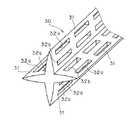
この通信ケーブルは、上記第1の実施の形態に係る通信ケーブルの介在芯10に代えて、図4に示す介在芯30を備えている。
【0040】
この介在芯30は、複数の介在片31が所定の中心軸から放射状に延設された構成とされ、断面略放射状の長尺形状を有している。本実施の形態では、4枚の介在片31が中心軸から放射状に延設されてており、介在芯30の断面形状が略十字状に形成されている。勿論、介在片31の数及び介在芯30の放射状断面形状は、対撚り線の数に応じて適宜変更される。
【0041】
上記各介在片31は、隣合う各対撚り線間に介在して、当該隣合う各対撚り線間の距離を一定以上に保つ機能を有している。具体的には、各介在片31は、前記中心軸方向に沿って延びる帯板状で、かつ、前記中心軸からその外側端縁部に向けて順次薄肉となる形状に形成されている。そして、隣合う各対撚り線間の距離寸法が、介在片31の幅方向中央部の厚み寸法以上に保たれるようになっている。
【0042】
また、各介在片31には、その長さ方向(前記中心軸方向)に沿って部分的に欠除部32a,32bが形成されている。具体的には、各介在片31の幅方向中央のラインを挟む2列に沿って、間隔をあけて複数の欠除部32a,32bが形成されている。各欠除部32a,32bは、該介在片31の長さ方向に沿って延びる略矩形孔状に形成されている。
【0043】
この通信ケーブルでは、各介在片31が隣り合う対撚り線間に介在するため、隣合う各対撚り線間の距離は、介在片31の外形の厚み寸法分以上に保たれる。また、各介在片31に欠除部32a,32bが形成されているため、各対撚り線間に介在する、比較的誘電率の小さな空気の占有率を大きくできる。従って、静電結合に起因する漏話特性をより向上させることができる。
【0044】
なお、欠除部32a,32bの形成箇所は、上記のものに限られない。例えば、欠除部32a,32bは、各介在片31の長さ方向に沿って一列又は3列以上の各列に沿って形成されていてもよく、また、千鳥足状に配置してあってもよく、さらに、各介在片31の幅方向中央部に形成されていてもよい。また、欠除部32a,32bの形状・大きさも、上記のものに限られない。例えば、三角孔形状、円孔形状であってもよい。
【0045】
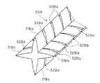
また、図5は、本実施の形態の変形例に係る介在芯30Bを示している。
【0046】
この介在芯30Bでは、欠除部32Ba,32Bbは、各介在片31Ba,31Bbの外側端部から介在芯30Bの中心軸に至る切込み状に形成されている。
【0047】
また、隣り合う介在片31Baに形成される欠除部32Ba,32Bbは、中心軸方向に沿って互いにずらして形成されている。即ち、互いに対向する介在片31Ba(図5の左右で対向している)又は介在片31Bb(図5の上下で対向している)では、欠除部32Ba又は欠除部32Bbが中心軸方向に沿って同位置に形成されている。また、互いに隣り合う介在片31Baと介在片31Bbとでは、各欠除部32Baは各欠除部32Bb間の中央位置に、又、各欠除部32Bbは各欠除部32Ba間の中央位置に形成されている。これにより、介在芯30Bが極端に容易に千切れたりすることがないようにしている。
【0048】
この介在芯30Bを備えた通信ケーブルでは、第3の実施の形態と同様の効果を奏する他、各介在片31Ba,31Bbに切込み状の欠除部32Ba,32Bbが形成されているので、曲げ易いという利点がある。また、介在芯30Bを切る際には、欠除部32Ba,32Bbの形成部分で、該介在芯30Bを手等で容易にねじ切ることができるという利点がある。この場合、欠除部32Ba,32Bbの形成間隔を短くしておくことが好ましい。
【0049】
【発明の効果】
以上のように、この発明の通信ケーブルによると、前記各介在片のうち隣合う前記各対撚り線間に介在して当該各対撚り線に接触する部分よりも、前記中心軸側の部分、又は、前記中心軸側の部分及び先端側の部分の双方が薄肉に形成されているため、各対撚り線間の距離を一定以上の大きさに保ちつつ、薄肉に形成した部分により比較的誘電率の小さな空気の占有率を大きくできる。従って、静電結合に起因する漏話特性をより向上させることができる。
【0050】
特に、請求項4記載の発明によれば、各介在片のうちの少なくとも一部が中空に形成されているため、各対撚り線間の距離を一定以上の大きさに保ちつつ、中空に形成した部分で、比較的誘電率の小さな空気の占有率を大きくできる。従って、静電結合による漏話特性をより向上させることができる。
【図面の簡単な説明】
【図1】 この発明の第1の実施の形態に係る通信ケーブルを示す断面図である。
【図2】 同上の実施の形態の変形例に係る通信ケーブルを示す断面図である。
【図3】 この発明の第2の実施の形態に係る通信ケーブルを示す断面図である。
【図4】参考例に係る第3の実施の形態に係る通信ケーブルを示す断面図である。
【図5】 同上の実施の形態の変形例に係る通信ケーブルを示す断面図である。
【符号の説明】
2 対撚り線
5 絶縁心線
8 外皮
10,10B,20,30,30B 介在芯
11,11B,21,31,31Ba,31Bb 介在片
11a,11Ba 接触介在部
21b 中空
32a,32b,32Ba,32Bb 欠除部[0001]
BACKGROUND OF THE INVENTION
The present invention relates to a communication cable used for a LAN or the like.
[0002]
[Prior art]
In a communication cable having a plurality of twisted wires (also referred to as twisted pairs), the crosstalk characteristics due to electrostatic coupling between the twisted wires are determined by the distance between the twisted wires and the substance interposed between the twisted wires. It is affected by the dielectric constant.
[0003]
Generally, an interposition core having a substantially cross-shaped cross section is interposed between the twisted wires to ensure the distance between the twisted wires and to improve the crosstalk characteristics between the twisted wires.
[0004]
An example of this type of communication cable is disclosed in Japanese Patent Application Laid-Open No. 11-283449.
[0005]
[Problems to be solved by the invention]
However, in the communication cable as described above, the dielectric constant of the interposition core interposed between each pair of stranded wires is relatively larger than the dielectric constant of air. For example, when the interposition core is generally made of polyethylene, the dielectric constant ε of polyethylene is about 2.3, which is larger than the dielectric constant of air (ε is approximately 1). For this reason, the improvement effect of the crosstalk characteristic resulting from electrostatic coupling will become inadequate.
[0006]
Then, the subject of this invention is providing the communication cable which can improve a crosstalk characteristic more.
[0007]
[Means for Solving the Problems]
In order to solve the above-mentioned problem, the communication cable according to
[0008]
As described in
[0009]
In addition, as described in
[0010]
Furthermore, as described in claim 4, at least a part of each of the intervening pieces may be formed hollow.
[0012]
DETAILED DESCRIPTION OF THE INVENTION
{First embodiment}
A communication cable according to the first embodiment of the present invention will be described below.
[0013]
As shown in FIG. 1, the communication cable includes a plurality of (four in this case) twisted
[0014]
Each pair of stranded
[0015]
The
[0016]
Each of the intervening pieces 11 has a function of interposing between the adjacent
[0017]
In the present embodiment, since the four
[0018]
In addition, at least a part of the interposition piece 11 except for a
[0019]
In addition, here, each adjacent
[0020]
In the present embodiment, the
[0021]
A portion of each interposition piece 11 on the front end side with respect to the
[0022]
The
[0023]
According to the communication cable configured in this manner, the
[0024]
In addition, the shape which makes thin the part except each
[0025]
Moreover, like the
[0027]
In addition, in this communication cable, since the crosstalk characteristic can be improved as described above, the distance between each pair of stranded
[0028]
{Second Embodiment}
Next explained is a communication cable according to the second embodiment of the invention.
[0029]
As shown in FIG. 3, the communication cable includes a plurality (four in this case) of twisted
[0030]
Each pair of
[0031]
The
[0032]
Each of the intervening
[0033]
At least a part of each intervening
[0034]
In the present embodiment, each
[0035]
In this communication cable, each interposed
[0036]
The outer shape of the
[0037]
Even in this communication cable, the crosstalk characteristics can be improved as described above, so that the distance between each pair of
[0038]
{Third embodiment}
Next, a communication cable according to a third embodiment accordingto thereference example will be described.
[0039]
This communication cable includes an
[0040]
The
[0041]
Each of the
[0042]
Each intervening
[0043]
In this communication cable, each
[0044]
In addition, the formation location of the
[0045]
FIG. 5 shows an
[0046]
In the intervening
[0047]
Further, the notch portions 32Ba and 32Bb formed in the adjacent interposition pieces 31Ba are formed so as to be shifted from each other along the central axis direction. That is, in the interposition piece 31Ba (opposite on the left and right in FIG. 5) or the interposition piece 31Bb (opposite on the top and bottom in FIG. 5) facing each other, the lacking portion 32Ba or the lacking portion 32Bb is in the central axis direction. It is formed in the same position along. Further, in the interposition piece 31Ba and the interposition piece 31Bb adjacent to each other, each notch 32Ba is at the center position between each notch 32Bb, and each notch 32Bb is at the center between each notch 32Ba. Is formed. This prevents the
[0048]
In the communication cable provided with the
[0049]
【The invention's effect】
As described above, according to thecommunication cable of the present invention,the part on the central axis side than the part in contact between each pair of twisted wires interposed between the adjacent pair of twisted wires of each of the interposed pieces, Alternatively, since both the central axis side portion and the tip side portion are formed thin, the distance between each pair of twisted wires is kept at a certain level or larger, and the portion formed thin is relatively dielectric. It is possible to increase the occupation ratio of air with a small rate. Therefore, the crosstalk characteristics resulting from electrostatic coupling can be further improved.
[0050]
In particular, according to the invention describedin claim 4 , since at least a part of each interposition piece is formed hollow, it is formed hollow while maintaining the distance between each pair of stranded wires at a certain size or more. In this portion, the occupation ratio of air having a relatively low dielectric constant can be increased. Therefore, the crosstalk characteristic due to electrostatic coupling can be further improved.
[Brief description of the drawings]
FIG. 1 is a cross-sectional view showing a communication cable according to a first embodiment of the present invention.
FIG. 2 is a cross-sectional view showing a communication cable according to a modification of the embodiment.
FIG. 3 is a cross-sectional view showing a communication cable according to a second embodiment of the present invention.
FIG. 4 is a cross-sectional view showing a communication cable according to a third embodiment according to areference example .
FIG. 5 is a cross-sectional view showing a communication cable according to a modification of the embodiment.
[Explanation of symbols]
2 Paired
Claims (4)
Translated fromJapanese前記各対撚り線を相互に隔てる複数の介在片が中心軸から放射状に延設された断面略放射状の介在芯と、を備え、
前記各介在片のうち隣合う前記各対撚り線間に介在して当該各対撚り線に接触する部分よりも、前記中心軸側の部分、又は、前記中心軸側の部分及び先端側の部分の双方が薄肉に形成された、通信ケーブル。A plurality of twisted wires formed by twisting a pair of insulated core wires; and
A plurality of intervening pieces separating each pair of twisted wires from each other, and having a substantially radial intervening cross section extending radially from a central axis,
The part on the central axis side, or the part on the central axis side and the part on the tip side than the part that intervenes between each pair of adjacent twisted wires among the intervening pieces and contacts the paired twisted wires Both of these are thin communication cables.
前記各介在片のうち隣合う前記各対撚り線間に介在して当該各対撚り線に接触する部分よりも中心軸側の部分がその中心軸側に向うに従って順次薄肉に形成されている、通信ケーブル。The communication cable according to claim 1,
The part on the central axis side is formed gradually thinner toward the central axis side than the part that is interposed between the adjacent twisted wires adjacent to each other among the intervening pieces and contacts the respective twisted wires, communication cable.
前記各介在片のうち前記各対撚り線間に介在して当該各対撚り線に接触する部分だけを厚肉に形成し、その他の部分を一様に薄肉に形成した、通信ケーブル。 A communication cable in which only a portion that intervenes between each pair of stranded wires and contacts with each pair of stranded wires is formed thick, and other portions are uniformly formed thin.
前記各介在片のうちの少なくとも一部が中空に形成された、通信ケーブル。 A communication cable in which at least a part of each of the interposition pieces is hollow.
Priority Applications (1)
| Application Number | Priority Date | Filing Date | Title |
|---|---|---|---|
| JP2002012991AJP3722064B2 (en) | 2002-01-22 | 2002-01-22 | communication cable |
Applications Claiming Priority (1)
| Application Number | Priority Date | Filing Date | Title |
|---|---|---|---|
| JP2002012991AJP3722064B2 (en) | 2002-01-22 | 2002-01-22 | communication cable |
Publications (2)
| Publication Number | Publication Date |
|---|---|
| JP2003217362A JP2003217362A (en) | 2003-07-31 |
| JP3722064B2true JP3722064B2 (en) | 2005-11-30 |
Family
ID=27650055
Family Applications (1)
| Application Number | Title | Priority Date | Filing Date |
|---|---|---|---|
| JP2002012991AExpired - Fee RelatedJP3722064B2 (en) | 2002-01-22 | 2002-01-22 | communication cable |
Country Status (1)
| Country | Link |
|---|---|
| JP (1) | JP3722064B2 (en) |
Cited By (3)
| Publication number | Priority date | Publication date | Assignee | Title |
|---|---|---|---|---|
| KR101490225B1 (en) | 2008-03-19 | 2015-02-05 | 콤스코프 인코포레이티드 오브 노스 캐롤라이나 | Separator tape for twisted pair in lan cable |
| US9418775B2 (en) | 2008-03-19 | 2016-08-16 | Commscope, Inc. Of North Carolina | Separator tape for twisted pair in LAN cable |
| US9978480B2 (en) | 2008-03-19 | 2018-05-22 | Commscope, Inc. Of North Carolina | Separator tape for twisted pair in LAN cable |
Families Citing this family (2)
| Publication number | Priority date | Publication date | Assignee | Title |
|---|---|---|---|---|
| WO2006050612A1 (en)* | 2004-11-15 | 2006-05-18 | Belden Cdt (Canada) Inc. | High performance telecommunications cable |
| KR100782229B1 (en)* | 2005-08-30 | 2007-12-05 | 엘에스전선 주식회사 | Communication cable with separator and spacer integrated inside |
- 2002
- 2002-01-22JPJP2002012991Apatent/JP3722064B2/ennot_activeExpired - Fee Related
Cited By (5)
| Publication number | Priority date | Publication date | Assignee | Title |
|---|---|---|---|---|
| KR101490225B1 (en) | 2008-03-19 | 2015-02-05 | 콤스코프 인코포레이티드 오브 노스 캐롤라이나 | Separator tape for twisted pair in lan cable |
| US9418775B2 (en) | 2008-03-19 | 2016-08-16 | Commscope, Inc. Of North Carolina | Separator tape for twisted pair in LAN cable |
| US9978480B2 (en) | 2008-03-19 | 2018-05-22 | Commscope, Inc. Of North Carolina | Separator tape for twisted pair in LAN cable |
| US10573430B2 (en) | 2008-03-19 | 2020-02-25 | Commscope, Inc. Of North Carolina | Separator tape for twisted pair in LAN cable |
| US11424052B2 (en) | 2008-03-19 | 2022-08-23 | Commscope, Inc. Of North Carolina | Separator tape for twisted pair in LAN cable |
Also Published As
| Publication number | Publication date |
|---|---|
| JP2003217362A (en) | 2003-07-31 |
Similar Documents
| Publication | Publication Date | Title |
|---|---|---|
| JP3636001B2 (en) | Twisted pair cable | |
| US8030571B2 (en) | Web for separating conductors in a communication cable | |
| EP1607985B1 (en) | Multi-pair data cable with configurable core filling and pair separation | |
| KR20120038349A (en) | Separator tape for twisted pair in lan cable | |
| US9318238B2 (en) | Hollow core body for signal transmission cable | |
| US20040118593A1 (en) | Flat tape cable separator | |
| US7157644B2 (en) | Reduced alien crosstalk electrical cable with filler element | |
| JP3722064B2 (en) | communication cable | |
| JP2005251608A (en) | Manufacturing method of stranded wire conductor, stranded wire conductor and electric wire | |
| JP2004311120A (en) | Communication cable | |
| JP2002367446A (en) | UTP cable | |
| JP3254179B2 (en) | Communication cable and method of manufacturing the same | |
| JP2002157926A (en) | Twisted pair cable | |
| JP2004362907A (en) | Interposition for UTP cable and UTP cable | |
| JP2008300248A (en) | communication cable | |
| JP5068663B2 (en) | Electrical cable with filler elements with reduced crosstalk | |
| JP3299064B2 (en) | Communication cable core and communication cable | |
| JP3636002B2 (en) | Twisted pair cable | |
| JP2009093908A (en) | Communication cable | |
| JP2010010091A (en) | Communication cable | |
| JP2002117730A (en) | Communication cable | |
| JP2001028208A (en) | communication cable | |
| JP2002117729A (en) | Communication cable | |
| JP3703805B2 (en) | Manufacturing method of communication cable | |
| JP2002352636A (en) | Multi-pair cable |
Legal Events
| Date | Code | Title | Description |
|---|---|---|---|
| A621 | Written request for application examination | Free format text:JAPANESE INTERMEDIATE CODE: A621 Effective date:20040611 | |
| A977 | Report on retrieval | Free format text:JAPANESE INTERMEDIATE CODE: A971007 Effective date:20050531 | |
| A131 | Notification of reasons for refusal | Free format text:JAPANESE INTERMEDIATE CODE: A131 Effective date:20050607 | |
| A521 | Written amendment | Free format text:JAPANESE INTERMEDIATE CODE: A523 Effective date:20050725 | |
| TRDD | Decision of grant or rejection written | ||
| A01 | Written decision to grant a patent or to grant a registration (utility model) | Free format text:JAPANESE INTERMEDIATE CODE: A01 Effective date:20050823 | |
| A61 | First payment of annual fees (during grant procedure) | Free format text:JAPANESE INTERMEDIATE CODE: A61 Effective date:20050905 | |
| R150 | Certificate of patent or registration of utility model | Free format text:JAPANESE INTERMEDIATE CODE: R150 | |
| FPAY | Renewal fee payment (event date is renewal date of database) | Free format text:PAYMENT UNTIL: 20090922 Year of fee payment:4 | |
| FPAY | Renewal fee payment (event date is renewal date of database) | Free format text:PAYMENT UNTIL: 20100922 Year of fee payment:5 | |
| FPAY | Renewal fee payment (event date is renewal date of database) | Free format text:PAYMENT UNTIL: 20100922 Year of fee payment:5 | |
| FPAY | Renewal fee payment (event date is renewal date of database) | Free format text:PAYMENT UNTIL: 20110922 Year of fee payment:6 | |
| FPAY | Renewal fee payment (event date is renewal date of database) | Free format text:PAYMENT UNTIL: 20110922 Year of fee payment:6 | |
| FPAY | Renewal fee payment (event date is renewal date of database) | Free format text:PAYMENT UNTIL: 20120922 Year of fee payment:7 | |
| FPAY | Renewal fee payment (event date is renewal date of database) | Free format text:PAYMENT UNTIL: 20120922 Year of fee payment:7 | |
| FPAY | Renewal fee payment (event date is renewal date of database) | Free format text:PAYMENT UNTIL: 20130922 Year of fee payment:8 | |
| LAPS | Cancellation because of no payment of annual fees |