JP3720053B2 - Monitor to detect internal body movement - Google Patents
Monitor to detect internal body movementDownload PDFInfo
- Publication number
- JP3720053B2 JP3720053B2JP50749396AJP50749396AJP3720053B2JP 3720053 B2JP3720053 B2JP 3720053B2JP 50749396 AJP50749396 AJP 50749396AJP 50749396 AJP50749396 AJP 50749396AJP 3720053 B2JP3720053 B2JP 3720053B2
- Authority
- JP
- Japan
- Prior art keywords
- monitor
- pulse
- path
- gate
- heart
- Prior art date
- Legal status (The legal status is an assumption and is not a legal conclusion. Google has not performed a legal analysis and makes no representation as to the accuracy of the status listed.)
- Expired - Fee Related
Links
Images


Classifications
- A—HUMAN NECESSITIES
- A61—MEDICAL OR VETERINARY SCIENCE; HYGIENE
- A61B—DIAGNOSIS; SURGERY; IDENTIFICATION
- A61B5/00—Measuring for diagnostic purposes; Identification of persons
- A61B5/05—Detecting, measuring or recording for diagnosis by means of electric currents or magnetic fields; Measuring using microwaves or radio waves
- A61B5/0507—Detecting, measuring or recording for diagnosis by means of electric currents or magnetic fields; Measuring using microwaves or radio waves using microwaves or terahertz waves
- A—HUMAN NECESSITIES
- A61—MEDICAL OR VETERINARY SCIENCE; HYGIENE
- A61B—DIAGNOSIS; SURGERY; IDENTIFICATION
- A61B5/00—Measuring for diagnostic purposes; Identification of persons
- A61B5/02—Detecting, measuring or recording for evaluating the cardiovascular system, e.g. pulse, heart rate, blood pressure or blood flow
- A61B5/024—Measuring pulse rate or heart rate
- A—HUMAN NECESSITIES
- A61—MEDICAL OR VETERINARY SCIENCE; HYGIENE
- A61B—DIAGNOSIS; SURGERY; IDENTIFICATION
- A61B5/00—Measuring for diagnostic purposes; Identification of persons
- A61B5/05—Detecting, measuring or recording for diagnosis by means of electric currents or magnetic fields; Measuring using microwaves or radio waves
- A61B5/053—Measuring electrical impedance or conductance of a portion of the body
- A61B5/0535—Impedance plethysmography
- A—HUMAN NECESSITIES
- A61—MEDICAL OR VETERINARY SCIENCE; HYGIENE
- A61B—DIAGNOSIS; SURGERY; IDENTIFICATION
- A61B5/00—Measuring for diagnostic purposes; Identification of persons
- A61B5/08—Measuring devices for evaluating the respiratory organs
- A61B5/085—Measuring impedance of respiratory organs or lung elasticity
- A61B5/086—Measuring impedance of respiratory organs or lung elasticity by impedance pneumography
- A—HUMAN NECESSITIES
- A61—MEDICAL OR VETERINARY SCIENCE; HYGIENE
- A61B—DIAGNOSIS; SURGERY; IDENTIFICATION
- A61B8/00—Diagnosis using ultrasonic, sonic or infrasonic waves
- A61B8/44—Constructional features of the ultrasonic, sonic or infrasonic diagnostic device
- A61B8/4416—Constructional features of the ultrasonic, sonic or infrasonic diagnostic device related to combined acquisition of different diagnostic modalities, e.g. combination of ultrasound and X-ray acquisitions
- A—HUMAN NECESSITIES
- A61—MEDICAL OR VETERINARY SCIENCE; HYGIENE
- A61B—DIAGNOSIS; SURGERY; IDENTIFICATION
- A61B8/00—Diagnosis using ultrasonic, sonic or infrasonic waves
- A61B8/48—Diagnostic techniques
- A61B8/488—Diagnostic techniques involving Doppler signals
- G—PHYSICS
- G01—MEASURING; TESTING
- G01S—RADIO DIRECTION-FINDING; RADIO NAVIGATION; DETERMINING DISTANCE OR VELOCITY BY USE OF RADIO WAVES; LOCATING OR PRESENCE-DETECTING BY USE OF THE REFLECTION OR RERADIATION OF RADIO WAVES; ANALOGOUS ARRANGEMENTS USING OTHER WAVES
- G01S13/00—Systems using the reflection or reradiation of radio waves, e.g. radar systems; Analogous systems using reflection or reradiation of waves whose nature or wavelength is irrelevant or unspecified
- G01S13/02—Systems using reflection of radio waves, e.g. primary radar systems; Analogous systems
- G01S13/0209—Systems with very large relative bandwidth, i.e. larger than 10 %, e.g. baseband, pulse, carrier-free, ultrawideband
- G—PHYSICS
- G01—MEASURING; TESTING
- G01S—RADIO DIRECTION-FINDING; RADIO NAVIGATION; DETERMINING DISTANCE OR VELOCITY BY USE OF RADIO WAVES; LOCATING OR PRESENCE-DETECTING BY USE OF THE REFLECTION OR RERADIATION OF RADIO WAVES; ANALOGOUS ARRANGEMENTS USING OTHER WAVES
- G01S13/00—Systems using the reflection or reradiation of radio waves, e.g. radar systems; Analogous systems using reflection or reradiation of waves whose nature or wavelength is irrelevant or unspecified
- G01S13/02—Systems using reflection of radio waves, e.g. primary radar systems; Analogous systems
- G01S13/50—Systems of measurement based on relative movement of target
- G01S13/58—Velocity or trajectory determination systems; Sense-of-movement determination systems
- G01S13/581—Velocity or trajectory determination systems; Sense-of-movement determination systems using transmission of interrupted pulse modulated waves and based upon the Doppler effect resulting from movement of targets
- G—PHYSICS
- G01—MEASURING; TESTING
- G01S—RADIO DIRECTION-FINDING; RADIO NAVIGATION; DETERMINING DISTANCE OR VELOCITY BY USE OF RADIO WAVES; LOCATING OR PRESENCE-DETECTING BY USE OF THE REFLECTION OR RERADIATION OF RADIO WAVES; ANALOGOUS ARRANGEMENTS USING OTHER WAVES
- G01S13/00—Systems using the reflection or reradiation of radio waves, e.g. radar systems; Analogous systems using reflection or reradiation of waves whose nature or wavelength is irrelevant or unspecified
- G01S13/02—Systems using reflection of radio waves, e.g. primary radar systems; Analogous systems
- G01S13/06—Systems determining position data of a target
- G01S13/08—Systems for measuring distance only
- G01S13/10—Systems for measuring distance only using transmission of interrupted, pulse modulated waves
- G01S13/18—Systems for measuring distance only using transmission of interrupted, pulse modulated waves wherein range gates are used
Landscapes
- Health & Medical Sciences (AREA)
- Life Sciences & Earth Sciences (AREA)
- Engineering & Computer Science (AREA)
- Physics & Mathematics (AREA)
- Remote Sensing (AREA)
- Radar, Positioning & Navigation (AREA)
- Public Health (AREA)
- General Health & Medical Sciences (AREA)
- Biophysics (AREA)
- Biomedical Technology (AREA)
- Heart & Thoracic Surgery (AREA)
- Medical Informatics (AREA)
- Molecular Biology (AREA)
- Surgery (AREA)
- Animal Behavior & Ethology (AREA)
- Pathology (AREA)
- Veterinary Medicine (AREA)
- Radiology & Medical Imaging (AREA)
- Nuclear Medicine, Radiotherapy & Molecular Imaging (AREA)
- Pulmonology (AREA)
- Computer Networks & Wireless Communication (AREA)
- General Physics & Mathematics (AREA)
- Cardiology (AREA)
- Physiology (AREA)
- Hematology (AREA)
- Measuring Pulse, Heart Rate, Blood Pressure Or Blood Flow (AREA)
- Measuring And Recording Apparatus For Diagnosis (AREA)
- Ultra Sonic Daignosis Equipment (AREA)
- Measurement Of The Respiration, Hearing Ability, Form, And Blood Characteristics Of Living Organisms (AREA)
- Traffic Control Systems (AREA)
- Burglar Alarm Systems (AREA)
- Selective Calling Equipment (AREA)
Abstract
Description
Translated fromJapanese発明の背景
本発明は心臓、肺およびその他の身体器官、組織および部材の動きを検出し、モニタし、さらに測定するための、および対応する生体電位信号を処理するためのモニタおよび方法に関するものである。
聴診器および音響モニタ
心肺モニタの分野では、生きている人または動物の心臓血管器官の鼓動を拾うためにマイクロホン装置、電気的装置、圧力装置または歪み計装置を用いることが一般的なやり方であった。19世紀の初めに、病んでいる組織により発生される音の特徴を調べることにより、生きている患者の胸の疾患を診断するためにラエネック(Laennec)によって発明された音響聴診器は、現在きわめて一般的に用いられており、過去100年にわたってほとんど元のままである。
既存の心肺モニタの例およびそれらの開発の趨勢の例を以下に示す。
それらのモニタ装置には大きな欠点がある。それらの装置の音響スペクトラムは低く、聴覚スペクトラムの下端部、すなわち、100Hzまたはそれ以下、内に含まれ、したがって、身体音を聴くことを困難にする。身体器官および部分はかなりの動きを示すが、それらは本質的に静かであり、それにより発生された音は非常に低くてかすかであり、十分な音響特質を与えない。
Chartinitski他の米国特許第4,248,244号明細書は、心臓の各鼓動に対応する電気的パルスを結合するための電極を持つ、心臓の鼓動を測定するための指示器を開示している。それらの電極は、心臓の鼓動ごとに発生される各電気的パルスに応じて交番する電気信号バーストを発生する回路に接続される。
したがって、心臓、肺およびその他の身体器官、組織または部材の壁の動きをモニタし、かつ対応する生体電位信号を処理するための非障害、非音響モニタおよび方法に対する需要が存在する。そのモニタはマイクロホン効果を大幅に減少しまたは完全に解消すべきであり、かつ衣服を通じて、またはある距離において身体内の動きを検出できなければならない。モニタは安価で、家庭における健康管理や、アスレチックスおよびスポーツ行事において専門家でない使用者が簡単に使用できなければならない。
超音波モニタおよび磁気共鳴
超音波モニタは身体器官の位置および動きを検出するために開発されてきた。それらのモニタは核磁気画像形成(NMI)装置/核磁気共鳴(NMR)装置などの、他の画像形成装置でも用いられてきた。既存の超音波モニタおよび磁気画像形成装置の例は次の通りである。
光学的画像形成装置
Slump他の米国特許第5,040,201号明細書に記述されている、心臓などの動いている物をモニタするための技術が、所与の位置に危険が予測される期間中のある時点に発生される周期的パルスに応じて、心臓の画像を形成するX線照射同期法である。
Swansonに付与された米国特許第5,321,501号の明細書に記載されている他の光学的画像形成法は試料の光学的画像形成を含む。これは、試料までの光路または基準反射器までの光路について相対的な光路長を変更することにより、または光源からの出力の光学特性を変更することにより、縦方向の走査または横方向の走査を行うものである。
したがって、体内器官、およびその他の構造、ならびに人または動物の体内に埋め込まれている外物の動きをモニタするために、既存のX線技術の代わりに使用でき、または既存のX線技術とともに使用できる新規な画像形成およびモニタ装置に対する需要が存在する。
発明の概要
本発明は、非常に短い電圧パルスの放射および検出を基にして心臓その他の器官の動きを検出するためのモニタおよび方法である。パルス=エコー・レーダー・モードが繰り返しモードで用いられる。そのモードでは、心臓の動きに対応するトーンを発生するために多数の反射パルスの平均を求めてオーディオ発振器を変調する電圧を発生する。このモニタで用いるアンテナは通常は2枚の平らな銅箔であるから、アンテナは十分に平らなハウジングの中に納めることができる。モニタは検出した電圧を、振幅変調されてドップラー効果を生ずる可聴音に変換する。それはセンサと表面の間の大きい動きの影響を減少するために二重時定数を用いる。
他の実施例は心臓と呼吸器との動きをマットレスパッドなどの物質を通じて検出し、モニタするための装置を含む。非接触動作範囲を12インチ(約30.5cm)より大きくすることができる。この装置はまたパルス=エコー・レーダー・モードでの非常に短い電圧パルスの放射および検出を基にしている。多数の反射パルスの平均を求めて心臓、動脈および肺からの反射により変調される電圧を発生する。
設計が相対的に簡単であるために、モニタは非常に安価に製作することができる。さらに、2ミクロンCMOSプロセスを基にして回路を1つの低コスト・シリコンチップに集積化することができる。心臓および呼吸器モニタ内のアンテナは、マット、マットレスまたはシートの背部に回路とともに埋め込むことができる簡単なワイヤで製作されて低コスト生命モニタを構成する、すなわち、マットの上に寝ている人または椅子に腰掛けている人がまだ生きているかどうかを判定するため、あるいはその人の生きている徴が変化した時を判定する。
1つの潜在的な応用は、がれきの下に埋められていたり、容易には見ることができないような人々などの、任意の環境において生きている人や動物の存在を動かない物体から見分けることである。そのような応用では、全体の動きを検出でき、または好ましいことであるが、呼吸を検出することができる。呼吸をモニタすることにより生きている人(または動物)と動かない物体(その物体が速く動いている(ジッグリング=jiggling)としても)との間で良く識別することができる。というのは、ジッグリングは通常2秒またはそれ以下の時間尺度(0.5Hzより高い)で起きるのに対して、呼吸は通常は2秒より長い時間尺度(0.5Hzより低い)で起きるからである。したがって、二重バンドフィルタにより、モニタは動かない物体のジッグリング運動と、生物の呼吸およびジッグリング運動とを識別することができる。このモニタを強化したものは、範囲を広げ/感度を向上させるために大出力送信器/ステップ発生器と、反射器アンテナとを含むことができる。したがって、それらのモニタは被災者の発見に有用である。
このモニタは心臓、肺、動脈、静脈などの身体内部の1つまたは複数の部分の機械的な動きや、胎児の心臓の鼓動、および声帯を非音響的に検出し、一連のパルスを伝送路とゲート路に同時に入力するためにパルス発生器を含む。伝送路に沿って伝送されたパルスは徴パルス発生器を駆動し、対応する送信パルスを供給する。それらの送信パルスは送信アンテナに加えられる。
ゲート路はタイミングを計られたゲートパルスを発生するレンジ遅延発生器を含む。タイミングを計られたゲートパルスは、身体部から反射されて、受信アンテナにより受けられるパルスを受信路に選択的に導通させる。モニタの出力電位を心臓の物理的運動を示す心臓出力と、肺の物理的運動を示す肺出力とに分離することができる。
モニタのタイミングを計られたゲートパルスはサンプルおよびホールド回路を受信路に沿ってゲートする。モニタは二重時定数回路をさらに含む。その回路では、肺の動きに対する大きなセンサ運動に対する小さいAC結合時定数があり、心臓の動きに関連する正常な信号レベルに対するはるかに大きいAC結合時定数がある。
【図面の簡単な説明】
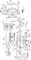
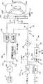
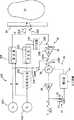
図1は本発明の心臓モニタのブロック図である。
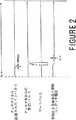
図2は図1のモニタのタイミング図である。
図3は全体として平らなハウジングの切り欠き図を示す、図1のモニタのアンテナ構成部の概略表現である。
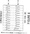
図4は心臓の近くの2か所の位置における、図1のモニタにより受けられる信号を描く2つのタイミング応答グラフを示す。
図5は種々の血管から反射された信号に対応する、図1のモニタにより受けられる信号を描く4つのタイミング応答グラフを示す。
図6は図1のモニタの回路図の例である。
図7は本発明の非接触心肺モニタのブロック図である。
図8は全体として平らなハウジングの切り欠き図を示す、図7のモニタのアンテナ構成部の概略表現である。
図9は図7のモニタにより受けられる信号を描く2つのタイミング応答グラフを示すものであって、上側のグラフは心臓と肺の応答を表し、下側のグラフは呼吸を停止した時の心臓の応答を表す。
図10はホモダイン回路を用いるモニタの他の実施例のブロック図である。
図11は図10のモニタの回路図の例である。
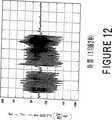
図12は図1のモニタをのどマイクロホンとして用いた、話された言葉「ワン・サウザンド」に対応し、かつその言葉を示すタイミンググラフである。
好適な実施例の詳細な説明
このモニタの全体的な動作は、送信アンテナからパルスを発射すること、短い期間待つこと、およびその後で、受信アンテナに接続されているゲートを開いて反射パルスを標本化できるようにすることを基にしている。このモニタを聴診器として使用する1つの応用では、待ち期間は組織内部の光の速さにおける1インチ(約2.54cm)の往復時間に対応する。モニタを非接触心肺モニタとして用いる他の応用においては、待ち期間は自由空間内(または自由空間と1インチ(約2.54cm)の組織の組合わせ)での光速における12インチ(約30.5cm)またはそれ以上の往復時間に対応する。呼吸は11フィート(約3.35m)の距離で検出できることが実験的に認められている。
このやり方を1MHzの繰り返し率で繰り返して約10000個の受信パルスの平均を求めてから、可聴表示器または光学的表示器を含めた(それに限定されるものではない)付属装置を駆動する。高いレベルの平均がサンプル信号に伴うランダムノイズを、極めて小さい振幅の信号を検出できるるような範囲にまで減少する。繰り返し動作によって全体の回路が極めて簡単にもなる。平均を求められたパルスにより、放射されたパルスと、ゲート時刻または受信アンテナに組合わされた標本化回路を動作させる時刻との間の遅延により決定される距離でのレーダー反射度に対応する。「距離ゲーティング」と称するこのプロセスにより器官、組織、膜または走査されるその他の構造についての深さ情報が得られる。
このモニタは「距離ゲート」(すなわち、走査される領域)の掃引、走査または画像形成を行うことができ、かつ所定の深さにおける反射度を検出する。心臓の筋肉が距離ゲートを通って動くと、それは距離ゲート内の反射度を変化する。それらの原理を基にした動きセンサが、1994年11月1日に付与された、Thomas E.McEwanによる「超広帯域レーダー運動センサ(Ultra−Wideband Radar Motion Sensor)」という名称の米国特許第5,361,070号明細書に記載されている。ゲートは放出されたパルスの幅に等しい持続時間の間だけ通常開いたままにされる。本発明は、1994年9月6日に付与された、Thomas E.McEwanによる「超広帯域受信器(Ultra−Wideband Receiver)」という名称の米国特許第5,345,471号明細書に記載されている超広帯域受信器をも利用する。
したがって、本発明は、電圧パルスの往復時間を計るというパルス=エコー・レーダーの原理を基にしている。ここで使用するレーダー・インパルスという用語は短い放射されパルスを指す。そのパルスは、従来のレーダー技術で使用されている長い正弦波バーストの代わりに用いられる。インパルス・レーダーに使用する特定の周波数はなく、それよりも、それの周波数スペクトラムがインパルスのフーリエ変換により関連させられる。自由空間に放射されるインパルスは幅が約200psの半正弦波パルスである。アンテナは通常は電圧パルス中の最高周波数成分の波長の半分より短い。インパルスレーダーの重要な利点の1つはスペクトラムができるだけ低く配置されており、その場所のスペクトラムでは組織の減衰が最小であることである。他の利点には簡単であること、および低コストであることが含まれる。
図1はモニタ1を示している。この特定の応用では、モニタ1を聴診器として使用する。しかし、モニタ1は他の種々の応用対象に使用できることが明らかである。
ノイズ発生器9がパルス繰り返し率/パルス繰り返し間隔(PRF/PRI)発生器10を変調して、平均が1MHzで、1MHzを中心とする1ないし10%のランダム変化を行う、すなわち、1ないし10%のPRF振動を行う、PRFを生ずる。振動はアンテナTからの放射スペクトラムを拡張して他のスペクトラムユーザーに対する潜在的な妨害を減少し、かつ振動は受信アンテナRに現れて受信標本化器26により取られる外部妨害信号の標本をランダムにもする。アンテナRにより受信された信号は標本化されて、平均を取られる。ランダムにされた標本は平均を取られると零になって、RF送信器などの他の源からの妨害をほとんど無くす。所望のエコーは送信されてから固定された短い時間の後で受信されるために振動により影響を受けず、かつ次の繰り返し間隔の正しい開始時刻により影響を受けない。振動によりスペクトラムを従来のRFユーザーに使用できるようにされ、かつ多数のインパルスモニタを近接して使用できるようにされる。他のインパルス・システムから放射された短いパルスを標本化する機会はランダムかつ極めて少数であり、他のインパルス・システムからの十分なパルスを順次標本化して検出可能な相関信号を生ずる確率は極めて低い。
1MHzパルス繰り返し周波数/間隔(PRF/PRI)発生器10からのパルスは、送信路12とゲート路14との2つの平行な経路に入力される。送信路12ではPRF/PRI発生器10はインパルス発生器16を駆動する。そのインパルス発生器16はパルス幅が200psである5V送信パルスを発生して、それを送信アンテナ(T)18に供給する。
受信アンテナ(R)20は走査されている試料から反射されたパルスを拾い、それを標本化・保持(S/H)回路26に供給する。その回路はゲート路14からのゲートパルスによりゲートされる。試料は、胸壁24の背後の心臓、胎児、卵巣、声帯、骨、血管の詰まり(血腫)、脳、脊髄、筋肉、前立腺、甲状腺膜(thyrohyoid)などを含むが、それらに限定されない、身体器官とすることができる。説明を簡単にするために、物体の例として心臓22を用いることにする。ゲートパルスは、送信アンテナ18がパルスを放射したときから約2ns遅延させられる。送信路12に入力されたPRF/PRI発生器10からのパルスがゲート路14に同時に入力され、そこでそれらは距離遅延発生器30とその後に続くインパルス発生器32とを通る。そのインパルス発生器はゲートスイッチ34を制御するための200nsゲートパルスを発生する。
遅延発生器30のレンジを調整可能に管理してモニタ1の深さ感度すなわち距離ゲートを制御する。この例では、パルスは2ns秒遅延させられるから、モニタ1の距離は組織内部で1インチないし2インチ(約2.54cmないし約5.08cm)である。距離ゲートからの反射パルスが受信路15に沿って標本化・保持回路(S/H)26に入力されるように、ゲートパルスがスイッチ34を閉じる。
好適な実施例におけるS/H回路26は接地されたコンデンサ28を含む。アンテナ20から約1ないし2インチ(約2.54ないし5.08cm)で起きる反射、またはそれがないこと、がそれにより標本化される。標本化・保持回路26中のコンデンサ28の容量は十分に大きいために、各標本はそれを部分的にのみ充電し、回路が受信アンテナ信号との平衡に達するためには約10000個の標本を要する。1つの設計例では、コンデンサ28は100pF程度である。受信アンテナ20のインピーダンスとコンデンサ28の容量との積がゲートパルスの幅よりはるかに大きい時定数を生ずるから、コンデンサ28を充電するためには多くのパルスを要する。
タイミングの相互関係を図2に示す。1パルス繰り返し間隔(PRI)にわたって4種の波形を示している。200ps幅のインパルスが送信アンテナ18から放射される。受信アンテナ20から反射されるインパルスはゲートパルスに一致する。各受信パルスはS/H回路26のコンデンサ28に増分電圧変化ΔVを生ずる。コンデンサ電圧は平均化S/H回路26の出力である。全受信パルスの増分ΔV=1/N(ただし、Nは平均を求める標本の数)は通常は約10000であるが、Nは異なる値を取ることができる。
標本化・保持回路26におけるノイズ電圧は、平均を取られる標本の数の平方根に関連する値、この場合は100分の1、だけ減少させられ、かつシステムのPRFと標本化器の瞬時帯域幅とに対する平均化回路の実効時定数に関連する値(標本化・保持回路26の標本化されたデータの性質に由来する値)だけ減少させられる。全部で、帯域幅、すなわち、放射されるパルスの帯域幅、が2GHzである回路と比較される60dBより大きなノイズ減少が達成される。
標本化・保持出力が電圧加算素子すなわち加算器36に加えられる。その加算器は背景反射をここで説明するようにして差し引く。加算器36の出力が増幅器(A)38により増幅される。この増幅器の利得は通常は60dBであって、通過帯域はDCから16Hzまでである。方形波発生器すなわち発振器39の出力に増幅器38からの電圧のAC結合された振幅が、掛算器37により乗ぜられ、かつ増幅器38からの信号の変化率によりその出力が周波数変調され、それにより、心臓筋肉の動く速度に関連させられたドップラー効果を生ずる。増幅器38の出力は帯域通過フィルタ(BPF)44(29〜500Hz)に加えられ、心臓の鼓動などの試料の動きを可聴検出できるようにするためにそこから選択スイッチ45へへ供給される。
低域フィルタ(LPF)46が20Hzより低い周波数を通す。それは増幅器38の出力端子に接続される。変化率は微分回路40から得られる。その微分回路は、簡単にした設計で、通常は1μF(マイクロファラッド)程度のコンデンサ40Cと、通常は10キロオーム程度のシャント抵抗とを含むRC回路で構成することができる。低域フィルタ41を用いて増幅器37の出力端子における結果としての調波を減衰して、イヤホン、スピーカーまたはヘッドホン42を介して心地好い可聴音を生ずる。
増幅器38の出力端子における生体電位信号を帯域通過フィルタ44およびヘッドホン42への入力として、および掛算器37の出力端子における生体電位信号を低域フィルタ41への入力としてそれぞれ示しているが、それらの生体電位信号はコンピュータまたは他の装置あるいはシステム43に交互に接続でき、または同時に接続できることが明らかである。光学的表示と、それらの装置またはシステムの駆動と、それらの装置またはシステムと共に動作することの少なくとも1つを行うために、それらの装置またはシステムは光学的表示器を含む。表示器は光学的なものに限定されるものではない。光学的表示器を用いたとすると、その表示器は、加えられた光に比例して順次発光する発光ダイオード(LED)装置を含む。その電圧は心臓22から反射されたパルスの反射の大きさに直線的に関連させられる。
方形波発生器39は、受信アンテナ20に現れる1マイクロボルトに対応するレベルで知覚できるようにして応答する。標本化・保持回路26と、加算器36と、増幅器38とにおける系統誤差は数十ミリボルトに達することがあるから、細い動脈によってひき起こされる1μV(マイクロボルト)などの、小さい変化を検出するためにその誤差を差し引かなければならない。また、胸壁24からの表面反射が差し引かなければならない誤差電圧に寄与する。
このために、平衡に達するまで、増幅器38の帰還路50中の積分器48が増幅器38の出力をサーボして、積分器48に加えられる基準電圧に増幅器38の出力が等しくさせられる。積分器のDC利得が極めて高いから、増幅器39の出力と基準電圧との間の電圧差は無視できる値まで減少させられる。増幅器38の帰還路50中の積分器48はそれの前方路中の微分器に等しい、すなわち、それは増幅器をそれがAC結合されているかのように動作させる。積分器48を使用することの利点は、それがモニタバイアス電流を供給し、増幅器38中の誤差を差し引き、二重時定数を簡単に実現できるようにすることである。
増幅器/積分器回の全体の動作は、患者の胸に対するセンサの全体的な動きに関連させられる大きい信号に対して、小さいAC結合時定数が存在し、心臓の動きに関連させられる正常な信号に対して、心臓の動きを忠実に再生できるようにするはるかに大きいAC結合時定数が存在することである。二重時定数は、2個のダイオード52,53と、それらに並列接続された抵抗51Rとで構成された二重時定数回路51により与えられる。通常、抵抗51Rは1MΩ(メグオーム)程度で、ダイオード52,53は1N4148などの共通コンピュータ型ダイオードである。
グラフで示してはいないが、モニタ1を試料(すなわち、心臓22)に対して縦または横に動かして二次元走査または多次元走査を行うために、適当な直線変換段またはその他の機構をモニタ1に接続することができる。他の縦方向または横方向にモニタ1を動かして試料の多次元走査を行うために類似の機構を設けることができる。
図3はアンテナ18,20の構造形状を示すものである。斜め上方から見た斜視図で概略的に示すように、送信アンテナ(T)18と受信アンテナ(R)20を、銅箔で製作した全体として長方形のパッチアンテナとして示す。そのアンテナの横寸法は1/4〜1インチ(約0.63〜2.54cm)の範囲内である。それらのアンテナ18,20は回路盤55の誘電体保持基板55Aの上に形成され、かつ銅などの、金属接地平面板55Bに接続される。この特定の例では、回路盤55の幅は2インチ(約5.08cm)で、それの長さLは約4インチ(約10.3cm)である。アンテナ18,20は、厚さDが約0.75インチ(約1.9cm)である全体として平らで薄いハウジング55Hに納められる。
接地平面板55Bとアンテナ18,20との間に電磁界が発生されて広帯域モノポールを形成する。そのモノポールは、胸などに、高誘電率物質に良く結合する。アンテナ18,20は小さい距離のモニタを行うためのものであって、空気の誘電率より高い誘電率を持つ身体内部での波を伝播させるための寸法になされる。その結果、距離ゲートの設計においては、またはモニタ1を「距離ゲートする」時は、体組織内の電磁波の伝播速度が空気中のそれより低いことを考慮に入れる。そのために、自由空間内の伝播インピーダンスZ0(空間)は、
Z0(空間)=√(μ0/ε0)
である。ここに、μ0は真空中のの透磁率、ε0は真空中の誘電率である。εr=40である物質(たとえば、筋肉または体組織)中の伝播インピーダンスZ0(筋肉)は、
Z0(筋肉)=√(μ0/(εr・ε0))=Z0(空間)/√εr=Z0(空間)/√(40)
である。筋肉の伝播インピーダンスは60オームであり、血液(εr=60)の伝播インピーダンスは49オームである。インピーダンスの違いにより心臓の筋肉とそれの血液との間の反射の大きさが異なってくる。
時間領域反射法(TDR)と同等に扱うことができる、伝送線に沿う伝播に似る一次元伝播においては、心臓筋肉からの反射は伝送線の不連続部からのの反射に等しくなる。放射されたパルスのどの部分が戻されたかを決定するために、(Y−1)/(Y+1)、Y=Z(心臓),と定義される反射係数、Γ、を適用することができる。たとえば、εr=40である心臓筋肉の反射の大きさは血液に対して、9.9%である。したがって、心臓筋肉が存在する時と、存在しない時との間の反射の大きさの違いは9.9%である。
1つの特定の応用においては、ペースメーカーのリード22L(図1に破線で示す)などの金属物体が心臓22の内部に設けられているか、機械的な弁22V(図1に破線で示す)を使用したとすると、金属は体組織から容易に弁別され、かつそれの反射の大きさの何倍も有するから、金属物体に対しては1.0というように、反射は非常に高い。リード22Lの場合のように、金属物体の横断面が非常に小さいとしても、ワイヤの分極とアンテナの分極が一致している(これは一般にリード22Lに対する場合と、モニタ1が垂直に向けられている場合とである)限り実際には依然として容易に弁別される。
本発明は胸壁24の第1の表面からの可変反射の大きさから生ずる大きな制約を克服するものである。第1の表面反射が変化するという問題は、後シュートまたはリンギング=アンテナを介してパルスを放射する時の一般的な効果のいずれかを含むパルスを放射することによりひき起こされる。時間的に後で放射されるものは、意図する距離ゲート54より近い物体または組織から反射された時、すなわち、変位させられた距離ゲートが存在する時に、標本化器のゲートに入る。したがって、リンギング成分は胸壁24の前面から反射され、同時に心臓22からの反射に包み込まれる。それらの前面反射は所望の反射を全く超えることがある。
この問題は、半正弦波形で、リンギングのない特定の波形を放射することにより解決される。したがって、一実施例においては、モニタ1は所望の波形を有するパルスを放射する。これは送信アンテナ18を適切に設計することにより行うことができる。この場合、半正弦パルスにより定められる1/4波長に対して寸法が小さい。その波形がリンギング、またはきれいな半正弦波形インパルスから外れた成分を含んでいるものとすると、距離ゲート54内を動く心臓筋肉の応答は多数のパルスを含み、知覚される心臓鼓動を実効的に増大する。したがって、送信アンテナ18と受信アンテナ20はリングしてはならないから、両方のアンテナは抵抗で終端し、かつ両方とも寸法が1/4波長より短い。
図4は、心臓に近い2箇所で、図1のモニタ1が受けた信号を描いた2つのタイミング応答図を示すものである。図5は左頸動脈、左手首、上腕動脈、左大腿動脈から反射された信号に対応する、モニタ1により受信された信号を描いた4つのタイミング応答図を示している。
距離ゲートのタイミングは2つの距離ゲート54と54A(図1に破線で部分的に示している)の間で交番することができる。対応する検出電圧を、「超広帯域レーダー運動センサ(Ultra−Wideband Radar Motion Sensor)」という名称の米国特許第5,361,070号の明細書に記載されているように、別々のS/H回路に蓄積することができる。
第2の距離ゲート54Aの動作は第1の距離ゲート54の動作に類似し、各距離ゲート54,54Aは独立に制御し、セットをすることができる。その結果、独立距離ゲート54,54Aからの反射度を独立に処理することができ、または一緒に処理することができる。たとえば、心臓22の前部壁22Fを検出するために第1の距離ゲート54をセットし、心臓22の後部壁22Fを検出するために第2の距離ゲート54Aをセットするものとすると、心臓の収縮および膨張サイクルおよび状態に関連する重要で貴重な情報を集めることができる。
二重距離ゲート54,54Aを使用することにより「ステレオ」効果が得られる結果となる。このステレオ効果により聴取者は心臓22の前部壁と後部壁の間に知覚的に置かれる。追加の距離ゲートを使用することができる。
図6はモニタ1の回路実施例を示すものである。2MHz PRF/PRI発生器10とノイズ発生器9が直列接続されている2つのインバータ(I1)60および61により集合的に構成される。インバータ60の出力端子とインバータ61の入力端子との間にコンデンサ62が接続され、インバータ60の出力端子と入力端子の間にシャント抵抗63が接続される。PRF/PRI発生器10の後にインバータ(V1)64で構成されたバッファと、コンデンサ66とシャント抵抗67で構成されたパルス幅制限器65とが設けられる。パルスは、トランジスタQ1=BFW92で構成されているインパルス発生器16へ進む。そのトランジスタのコレクタは抵抗RTを介して送信アンテナ18に接続される。PRF/PRI発生器10からのパルスは第2の遅延発生器30を通る第2の経路も通る。その遅延発生器は可変抵抗RXと、漂遊容量と、バッファゲート(I1)の入力容量とで構成される。遅延させられたパルスは、他のトランジスタQ2=BFW92で構成されているインパルス発生器32に入力される。そのインパルス発生器はゲートパルスを発生する。ここで、64Aはパルス幅制限器、68はインバータである。
反射された信号は受信アンテナ20により受信され、S/H回路コンデンサ26に入力される。そのコンデンサは、ショットキーダイオードD1=MBD701を通るゲートパルスによりゲートされる。S/H回路26からの出力が増幅器(I2)38に入力される。増幅器38の出力は測定した生体電位を表し、ヘッドホン42(図1)などの種々の装置と計器の少なくとも1つにより使用し、それに接続し、または処理することができる。好適な実施例においては、I1=74HCO4、I2=TLC274である。更に、伝播パルスは数インチ(約13cm)の空隙または物質(筋肉、血液など)を横切って容易に放射する。
増幅器38の出力端子は増幅回路70に接続されて増幅38の利得を更に高くする。増幅回路70は演算増幅器71を含む。その演算増幅器は抵抗72を介して増幅器38の出力端子に接続される。演算増幅器は、並列接続されているコンデンサ73と抵抗74によりシャントされる。
モニタの出力レベルが所定の上しきい値レベルと下しきい値レベルを超えるかどうかを検出するために、増幅器71の出力端子はしきい値検出器回路網75に接続される。しきい値検出器回路網75は2つの比較器または演算増幅器76,77(I3=TLC724)を全体として有するそれらの比較器の出力は2個のダイオード78,79と抵抗80を介して組合わされ、スイッチ81(Q3)に供給される。動作時は、上しきい値レベルと下しきい値レベルのいずれかをを超えたとすると、対応する演算増幅器76または77がスイッチ81を導通状態に駆動する。その後でスイッチ81の出力を使用して警報またはその他の適切な回路を作動させることができる。たとえば、ペースメーカーとともに、またはペースメーカーの一部としてこのモニタを使用するものとすると、ペーシングを開始または禁止するために、スイッチ81の出力は、適切な抵抗82を介して検出されて、活動検出などの、所望の表示を行うことができる。演算増幅器76,77に加えられる信号の振幅を制御するように、しきい値検出器回路網75の感度はポテンショメータ84により調整することができる。
電圧整流器ネットワーク86がPRF/PRI発生器10に接続されて−3V(ボルト)をモニタの、増幅器71などの種々の部品に供給する。電圧整流器ネットワーク86は0〜5Vの方形波電圧を供給するために2つの並列インバータ(I1)87,88を全体として含む。2個のダイオード89,90がコンデンサ91を介してインバータ87,88の入力端子に接続される。−3Vの定常出力電圧を発生するために、ダイオード90にシャントコンデンサ92が接続されて、電圧整流器ネットワーク86は方形波電圧を整流し、レベルを推移させる。増幅器回路70の出力端子に出力抵抗93が接続されて過大な電流が流れるのを阻止する。図6および図11の回路図に示す部品の多くのものの値は前記米国特許第5,345,471号および第5,361,070号の各明細書に定められている。
図7は他のモニタ100を示すものである。このモニタは図1のモニタ1と全体として類似するようにして動作するが、マットレスパッドまたは椅子の背もたれなどの物質を通じて心臓の動きや呼吸運動を遠隔で検出するために修正している。操作距離をより大きくするために、モニタ100のアンテナが改造されている。それにより可聴出力を検出した。しかし、当業者はこの特徴を選択的に付加することができる。距離制御を行うことができ、6フィート(約1.83m)の距離において呼吸を検出するために設定することができる。図1と図7において同一の参照番号は同一の機能を持つ同一の部品を示すものとする。
モニタ100の全体的な動作も、送信アンテナからパルスを発射し、短い時間を待ち、その後で、受信アンテナに接続されているゲートを開いて反射パルスを標本化できるようにする。しかし、モニタを非接触心肺モニタとして使用する場合は、待ち時間は自由空間(または自由空間と組織1インチ(約2.54cm)との組合わせ)内の光の速度で12インチ(約30.5cm)またはそれ以上の往復時間に対応する。
送信路112では、PRF/PRI発生器10はインパルス発生器116を駆動する。そのインパルス発生器は5V200ps幅の半正弦送信パルスを発生して、それを送信アンテナ(T)118に供給する。リンギングを避けるために、送信アンテナ118の電気長は半正弦波のスペクトル内容に対して短く設定される。
受信アンテナ(R)120は、肺122(前部壁122Fと後部壁122Rを有する)と胸壁の背後の心臓などの身体器官、または椅子124などの物体から反射されたパルスを拾い、それを標本化・保持(S/H)回路26に加える。その回路はゲート路114からのゲートパルスによりゲートされる。ゲートパルスは、送信アンテナがパルスを放射した時から約3nsだけ遅延させられる。アンテナ118と120から12インチ(約30.5cm)において起きる反射がそれにより標本化される。PRF/PRI発生器10からのパルスが送信路112に入力されると同時にゲート路114に入力され、そこでパルスは距離遅延発生器130と、それに続くインパルス発生器132を通る。そのインパルス発生器は、ゲートスイッチ34を制御するための200ps幅のゲートパルスを発生する。図2に示すタイミング関係はモニタ100にも加えられる。
受信路115では、加算素子36の出力が増幅器38により、0.05〜10Hzの通過帯域にわたって通常は70dB増幅されて、心臓帯域通過フィルタ141と肺帯域通過フィルタ142に選択的に加えられる。
図8は図7のモニタ100の部分を構成するアンテナ118,120の概略表現であって、全体として平らで薄いハウジング155Hの切り欠き図を示す。アンテナ118,120は直線ダイポールであって、送信素子118と受信素子120をそれぞれ有する。それらのアンテナは折り返すことができる。各素子は約0.5インチ×2インチ(約1.27cm×5.08cm)であるが、それより長くすることができる。アンテナはFCCの要求に応じて2GHz帯内の電磁波を放射することができる。アンテナ自体は自立しており、接地面155Bに結合する必要はない。接地面155Bがモニタ回路を保持する。保管・輸送を容易にするため、およびアンテナ素子の実効長を可変とするために、アンテナ素子118,120は望遠鏡のように伸縮させることができる。アンテナ素子118,120には、種々の応用のために、それの長さに沿って、マーキング点Pなどの、種々のマーキングでマークすることができる。たとえば、小児科での使用のためにマーキング点Pをアンテナ素子118,120を延ばした全長のおよそ半分の所に付けることができる。
波形が、きれいな半正弦波形インパルスからずれたリンギングまたは成分を含んでいるとすると、距離ゲート54を通じて動く心筋または肺の境界は多数のパルスを含んで、知覚した心臓鼓動を実効的に増大する。したがって、送信アンテナ素子118と受信アンテナ素子120を図6に示すようにそれぞれ抵抗RTとRRにより抵抗終端とすることにより、それらのアンテナ素子を非リンギングにする。こうすることにより、正味のT−R応答は、きれいな半正弦波形インパルスになる。
正確な、すなわち最適な距離遅延を有する距離ゲート54と54Aの少なくとも一方は次の式により決定することができる。
距離ゲート=1/2[進行時間(空気)+進行時間(組織)]
距離ゲート=[距離空気/C+距離組織√εr/C]
ここにCは光の速さ、εrは組織の誘電率である。実効応答距離を長くするために距離ゲート54のタイミングを1組の距離にわたって掃引することができる。さもなければ、12インチ(約30.5cm)に対して最適にした固定距離ゲートにより、心肺検出は0から12インチ(約30.5cm)までを守り、肺検出は0から18インチ(約45.7cm)までを守る。肺の動きを心臓の動きから分離して識別するために、心臓帯域通過フィルタ141および肺帯域通過フィルタ142(図7)が増幅器38の出力端子における信号を選択的に濾波する。通常は、心臓の鼓動は1分間当り40回またはそれ以下と1分間当り180回の範囲であるが、呼吸数は1分間当り2回から20回の範囲である。しかし、所望の応用に応じて他の範囲を選択することもできる。モニタ100の回路図は、図6に示すモニタ1の回路図に基本的に類似するから、増幅器38の出力端子におけるモニタの出力が2つの帯域通過フィルタ141と142に接続される。
図9はモニタ100が受けた信号を描く2つのタイミング応答グラフ(A)と(B)を示すものである。上側のグラフ(A)は心臓と肺の組合わせた応答を表し、下側のグラフ(B)は呼吸を停止している時の心臓の応答を表す。両方のグラフのためのデータが、モニタ100から12インチ(約30.5cm)の距離に位置している胸壁124で得られたものである。そのデータは増幅器38の出力端子における電圧または生体電位である。
図10はホモダイン回路を用いるモニタ200の他の実施例のブロック図である。ホモダイン回路はThomas E.McEwanにより1994年5月9日に出願された「電磁的に隠蔽されている物体の検出器(Electromaganetic Hiden Object Detector)」という名称のPCT特許出願、番号PCT/US94/04813号の明細書に記載されている。
モニタ200はAC結合された増幅器を受信路中に含む。この増幅器は、標本平均化および保持回路からモニタの出力端子にDC信号が進むのを阻止する。このAC結合された増幅器はS/H回路26におけるDCバイアスレベルの移動を除去する。送信器パルスをAC変調する。その後でそのAC変調を受信器において同期検波(ホモダイン技術)することにより、AC結合された増幅器を受信器に使用できるようにする。
要約すれば、ホモダイン動作のためにモニタ1と100を改造した、ということになる。ホモダイン技術は、PRF発生器からの信号を放射および検出の前に連続波(CW)信号で変調することを含む。その後で、CW信号に通過帯域の中心を置き、したがって、それをAC結合して受信増幅器が動作する。増幅の後で同じCW信号を用いてその信号を同期検出する。
モニタ200は、通常、数kHz(この例では2kHz)で動作するホモダイン発振器202と、PRF発生器204(図1に示すPRF発生器10に類似する)とを含む。このPRF発生器は通常、1MHzないし数MHzの範囲(この例では2MHz)で動作する。あるいは、ホモダイン信号は、平均周波数が数kHzのオーダーで、平均が零である任意のパルス列にすることができる。
ホモダイン発振器202とPRF発生器204からの信号がステップすなわちインパルス発生器206に供給され、そこでホモダイン発振器202はインパルス発生器206により発生されたステップ信号を振幅変調して、インパルス発生器を所望のホモダイン周波数、たとえば2kHz、で事実上ターンオンおよびターンオフする。したがって、インパルス発生器206により出力されて送信アンテナ218により送信される信号は、周波数が2kHzであるパルスの周期的パケットを含むから、各パルスは通常、周波数が2MHzで、バースト間隔が0.5msであるバースト(100個のパルスなどの)を構成する。
パルスが送信アンテナ218で送信されると、それらのパルスは動いている物体、たとえば心臓(または肺)22の壁から反射されて受信アンテナ220により受信される。心臓22から反射された信号は、送信されたパケットに対応し、周波数が2kHzである一連の周期的パルスで構成される。受信アンテナ220では、2kHz包絡線の振幅が心臓22からの反射に関連させられる。
モニタ200の一実施例においては、2kHz包絡線を積分器48からの所定の基準レベルを基準にして、モニタ200が基本的にモニタ1ないし100と同様に動作できるようにすることが望まれる。このために、受信器の標本化・保持回路26は2MHzバースト(パルス)を約0.1msの期間にわたって平均化するから、2kHzホモダイン周波数のみが標本化・保持回路26に残る。ホモダイン周波数はAC結合された増幅器229により増幅され、その後で同期検波器230AによりDCレベルに同期検波される。
同期検波器230Aはコンデンサ230Cと検波器スイッチ230Sを含む。検波器スイッチ230Sは飽和トランジスタを含み、コンデンサ230Cは通常は0.01μFのオーダーで、検波器スイッチすなわちトランジスタ230Sがホモダイン発振器202により導通させられた時に、検波器スイッチすなわちトランジスタの出力側における電圧の値を保持するために使用する。
AC増幅器229の利点はモニタのDCバイアスレベル、すなわち標本化・保持回路26におけるDCバイアスレベルが通ることを許されない(すなわち、それらが濾波されない)ことである。それらのDCバイアスレベルは電源変動と受信アンテナ220の近くに持ってこられた物質により変化する。同期整流器230Aの出力端子における整流されたDCレベルは心臓22から反射されたパルスを表す。モニタ20のこの後の動作はモニタ1,100の動作に類似する。
動作時は、検波器スイッチ230Sはホモダイン発振器サイクルの半分の間は閉じ、この半サイクル中はコンデンサ230Cを充電する。ホモダイン発振器サイクルの相捕(すなわち、残りの)半サイクル中はスイッチ230Sは開き、検波器230Aはホモダイン発振器202からの信号を検出しない。その結果、コンデンサ230Cに加えられた平均信号がAC結合された増幅器229の出力端子における信号(平均波)のピーク振幅を表し、それにより、標本化・保持回路26からのDC電圧からではなくて、心臓22からの反射信号に対するDC電圧を発生する。
コンデンサ230Cに生じたDC電圧は、心臓22から反射された所望の信号と、モニタハウジングおよびアンテナ−アンテナ直接結合を含む種々の源からの望ましくない信号とを加え合わせたものを表す。DC結合された増幅器38の出力はDC基準電圧に等しくされる。図11は図10のモニタ200の回路図の例である。このモニタはホモダイン発振器202を含む。このホモダイン発振器は通常、2個のCMOSインバータ15,151を含む。ホモダイン発振器202の出力端子はインパルス発生器206と同期検波器230Aに接続される。
モニタ200の回路の受信路はモニタ1と100のそれに全体として類似し、AC結合された増幅器229と同期検波器230Aを含む。AC結合された増幅器229は平均化する標本化・保持回路26と同期検波器230Aの間に接続される。同期検波器230Aは加算器36に接続される。AC結合された増幅器229はモトローラによる2つのMC14069UB CMOSインバータを含む。それらのインバータは増幅器として直線モードで用いる。同期検波器230Aはバイポーラトランジスタ、たとえばナショナル・セミコンダクタによる2N2222を含む。それらはホモダイン発振器202によりターンオンまたはターンオフされる。
DC結合された増幅器38は2つのMC14069UBインバータを含む。DC増幅器の出力は希望に応じて処理される。開示している実施例の回路を個別部品で説明したが、それらの回路は、代わりに、それらの部品を集積回路またはチップ上に集積化することにより超小型にすることができる。
モニタ1,100および200はいくつかの応用ではマイクロホンとして使用することもできる。たとえば、図12はのどマイクロホンとしてのモニタ1の使用を示すものであって、話し言葉「ワンサウザンド」に対応して、その言葉をグラフ的に示したものである。モニタ100と200はのどマイクロホンとして使用するのに適合させることもできる。動作時には、のどマイクロホンをのどぼとけの部分の上またはそのすぐ近くに配置し、声帯の動きを測定する。のどマイクロホンの1つの構成例においては、図1の増幅器38の帯域幅は20Hzないし3kHzであり、可聴音を発生するために電圧制御発振器なしにモニタ出力を使用することができる。
のどマイクロホンの他の応用の例は、声帯部を音響で励振することにより声帯部の病変その他の異常を識別することである。音響励振は口からのどへ向かって加え、のどマイクロホンを用いてその結果としての応答を記録する。病変その他の異常は異常な共鳴を生ずる。それをのどマイクロホンにより検出および測定する。同様に、鼓膜を励振させることができ、種々の診断目的のために対応する振動応答がマイクロホンにより検出され、記録される。
あるいは、このモニタ/マイクロホンを機械的すなわち音響的刺激源とともに使用することができる。一例として、音響ビームを腫瘍部に集中するものとすると、腫瘍はそれの特定の性質の所定の周波数特性で共鳴することがある。モニタ/マイクロホンはその共鳴運動を検出し、かつ腫瘍の種類と場所を識別することを支援することができる。また、モニタ/マイクロホンを用いて骨伝導を決定することができる。対象とする骨の一端に機械的すなわち音響的な刺激源を押し付け、モニタ/マイクロホンを骨の長さに沿う種々の場所に配置して、骨により刺激の伝播を測定および検出する。ひび割れおよび類似の異常が異常な音や不規則な音あるいは指示を発生させることができる。
肺の内部音を聴いて、特定の疾患すなわち病気に関連する症候を特徴付ける異常音や、その他の動きを検出するためにモニタ/マイクロホンを使用することができる。埋め込まれている金属製心臓弁その他の類似の物体の破損を識別するためにもモニタ/マイクロホンを使用することができる。たとえば、モニタ/マイクロホンは、機械的な心臓弁の反射度(すなわち、レーダー横断面すなわちRCS)の変化を欠陥として識別することができ、またはひび割れが断続的な電気的接触を生ずる。
応用のいくつかの例を示せば次の通りである。(1)モニタおよびそれの改造したものを埋め込んで心臓の壁の動きを検出し、かつ従来のペースメーキング原理および技術として、または従来のペースメーキング原理および技術とともに使用するようにするペースメーカー、(2)テレメータ技術、(3)蛍光透視法、(4)胎児モニタ装置、(5)身体内にある物体の検出器、(6)幼児突然死症候(SID)、(7)心電図(EKG)、(8)心音波図、(9)子宮、胎児、卵巣、骨、凝血、脳、脊髄、筋肉、前立腺、および甲状腺膜など(もっとも、それらに限定されるものではない)を含めた、種々の器官、部材または組織の画像を形成するための超音波装置、NMR、およびNMIなどの従来システムの代わりに、またはそれらのシステムと共に、モニタを使用できるようにする画像形成モニタ、測定モニタ、走査モニタおよび画像形成法、測定法、走査法、(10)骨折スクリーニングモニタ、(11)乳房レントゲン撮影法、(12)欠陥、肺の樹枝状気管支、胃腸管、生殖器管、または尿道などの筒状構造その他の構造の内部に、アンギオスコープ、内視鏡またはカテーテルを用いて挿入する内部案内装置または走査装置。以上は例示であり、それらに限定されるものではない。Background of the Invention
The present invention relates to monitors and methods for detecting, monitoring, and measuring the movement of the heart, lungs and other body organs, tissues and components, and for processing corresponding biopotential signals.
Stethoscope and acoustic monitor
In the field of cardiopulmonary monitors, it was common practice to use a microphone device, electrical device, pressure device or strain gauge device to pick up the heartbeat of a living person or animal. At the beginning of the 19th century, an acoustic stethoscope invented by Laennec to diagnose breast disease in living patients by examining the characteristics of sounds produced by diseased tissue is now extremely Commonly used and remains largely intact over the past 100 years.
Examples of existing cardiopulmonary monitors and examples of their development trends are given below.
These monitoring devices have major drawbacks. The acoustic spectrum of these devices is low and is contained within the lower end of the auditory spectrum, ie, 100 Hz or below, thus making it difficult to hear body sounds. Although the body organs and parts show considerable movement, they are inherently quiet and the sound generated thereby is very low and faint and does not give sufficient acoustic qualities.
US Pat. No. 4,248,244 to Chartiniski et al. Discloses an indicator for measuring heart beats with electrodes for combining electrical pulses corresponding to each heart beat. . The electrodes are connected to a circuit that generates an electrical signal burst that alternates with each electrical pulse generated with each heart beat.
Accordingly, there is a need for non-disruptive, non-acoustic monitors and methods for monitoring the motion of the walls of the heart, lungs and other body organs, tissues or members and processing the corresponding biopotential signals. The monitor should greatly reduce or completely eliminate the microphone effect and must be able to detect movement in the body through clothing or at a distance. Monitors should be inexpensive and easy to use for non-professional users in home health care, athletics and sporting events.
Ultrasonic monitor and magnetic resonance
Ultrasound monitors have been developed to detect the position and movement of body organs. These monitors have also been used in other imaging devices such as nuclear magnetic imaging (NMI) / nuclear magnetic resonance (NMR) devices. Examples of existing ultrasonic monitors and magnetic image forming apparatuses are as follows.
Optical image forming apparatus
At some point in time during which a technique for monitoring moving objects, such as the heart, described in Slump et al., US Pat. No. 5,040,201, is expected to be dangerous at a given location. This is an X-ray irradiation synchronization method for forming an image of the heart in accordance with the periodic pulse generated at the same time.
Another optical imaging method described in US Pat. No. 5,321,501 to Swanson involves the optical imaging of a sample. This can be achieved by changing the relative optical path length for the optical path to the sample or the reference reflector, or by changing the optical properties of the output from the light source, thereby allowing vertical or horizontal scanning. Is what you do.
Thus, it can be used in place of or in conjunction with existing X-ray technology to monitor the movements of internal organs and other structures, as well as foreign objects embedded in the human or animal body There is a need for new imaging and monitoring devices that can.
Summary of the Invention
The present invention is a monitor and method for detecting the movement of the heart and other organs based on the emission and detection of very short voltage pulses. Pulse = echo radar mode is used in repeat mode. In that mode, a voltage that modulates the audio oscillator is generated by averaging a number of reflected pulses to generate a tone corresponding to the heart motion. Since the antenna used in this monitor is usually two flat copper foils, the antenna can be housed in a sufficiently flat housing. The monitor converts the detected voltage into an audible sound that is amplitude modulated to produce a Doppler effect. It uses a double time constant to reduce the effects of large motion between the sensor and the surface.
Other embodiments include devices for detecting and monitoring heart and respiratory movement through materials such as mattress pads. The non-contact operating range can be greater than 12 inches (about 30.5 cm). This device is also based on the emission and detection of very short voltage pulses in the pulse = echo radar mode. A voltage that is modulated by reflection from the heart, artery, and lung is generated by averaging multiple reflected pulses.
Due to the relatively simple design, the monitor can be made very inexpensively. Furthermore, the circuit can be integrated on one low cost silicon chip based on a 2 micron CMOS process. The antennas in the heart and respiratory monitor are made of simple wires that can be embedded with circuitry on the back of the mat, mattress or seat to form a low-cost life monitor, i.e. a person sleeping on the mat or To determine if the person sitting on the chair is still alive, or when the person's alive sign has changed.
One potential application is to distinguish the presence of living people and animals in any environment from non-moving objects, such as people buried under debris or not easily visible. is there. In such an application, overall movement can be detected or, preferably, respiration can be detected. By monitoring respiration, a good distinction can be made between a living person (or animal) and a non-moving object (even if the object is moving fast (jigling)). This is because jiggling usually occurs on a time scale of 2 seconds or less (above 0.5 Hz), whereas respiration usually occurs on a time scale longer than 2 seconds (below 0.5 Hz). is there. Thus, the dual band filter allows the monitor to discriminate between the jiggling movements of non-moving objects and the breathing and jigging movements of living beings. This monitor enhancement can include a high power transmitter / step generator and a reflector antenna to increase range / sensitivity. Therefore, those monitors are useful for finding victims.
This monitor detects the mechanical movement of one or more parts of the body, such as the heart, lungs, arteries and veins, the heartbeat of the fetus, and the vocal cords non-acoustically, and transmits a series of pulses. And a pulse generator for simultaneous input to the gate path. The pulses transmitted along the transmission path drive the collection pulse generator and provide corresponding transmission pulses. Those transmit pulses are applied to the transmit antenna.
The gate path includes a range delay generator that generates a timed gate pulse. The timed gate pulse is reflected from the body part to selectively conduct the pulse received by the receiving antenna to the receiving path. The output potential of the monitor can be separated into a cardiac output indicating physical movement of the heart and a lung output indicating physical movement of the lung.
Monitored gated pulses gate the sample and hold circuit along the receive path. The monitor further includes a double time constant circuit. In that circuit, there is a small AC coupling time constant for large sensor motion relative to lung motion and a much larger AC coupling time constant for normal signal levels associated with heart motion.
[Brief description of the drawings]
FIG. 1 is a block diagram of the heart monitor of the present invention.
FIG. 2 is a timing diagram of the monitor of FIG.
FIG. 3 is a schematic representation of the antenna component of the monitor of FIG. 1, showing a cutaway view of the generally flat housing.
FIG. 4 shows two timing response graphs depicting the signals received by the monitor of FIG. 1 at two locations near the heart.
FIG. 5 shows four timing response graphs depicting signals received by the monitor of FIG. 1, corresponding to signals reflected from various blood vessels.
FIG. 6 is an example of a circuit diagram of the monitor of FIG.
FIG. 7 is a block diagram of the non-contact cardiopulmonary monitor of the present invention.
FIG. 8 is a schematic representation of the antenna configuration of the monitor of FIG. 7, showing a cutaway view of the generally flat housing.
FIG. 9 shows two timing response graphs depicting the signal received by the monitor of FIG. 7, with the upper graph representing the heart and lung response and the lower graph representing the heart when breathing is stopped. Represents a response.
FIG. 10 is a block diagram of another embodiment of a monitor using a homodyne circuit.
FIG. 11 is an example of a circuit diagram of the monitor of FIG.
FIG. 12 is a timing graph corresponding to the spoken word “One Thousand” using the monitor of FIG. 1 as a throat microphone and showing the word.
Detailed Description of the Preferred Embodiment
The overall operation of this monitor is based on firing a pulse from the transmit antenna, waiting for a short period of time, and then allowing the gate connected to the receive antenna to open and sample the reflected pulse. I have to. In one application using this monitor as a stethoscope, the waiting period corresponds to a round trip time of 1 inch at the speed of light inside the tissue. In other applications where the monitor is used as a non-contact cardiopulmonary monitor, the waiting period is 12 inches (about 30.5 cm) at the speed of light in free space (or a combination of free space and 1 inch of tissue). ) Or longer round trip times. It has been experimentally found that respiration can be detected at a distance of 11 feet.
This procedure is repeated at a 1 MHz repetition rate to average about 10,000 received pulses before driving ancillary devices including (but not limited to) audible or optical indicators. A high level average reduces the random noise associated with the sample signal to such a range that a signal with a very small amplitude can be detected. Repeated operation also makes the entire circuit very simple. The averaged pulse corresponds to the radar reflectivity at a distance determined by the delay between the emitted pulse and the gate time or the time to operate the sampling circuit associated with the receiving antenna. This process, referred to as “distance gating”, provides depth information about the organ, tissue, membrane, or other structure being scanned.
This monitor can sweep, scan or image the “distance gate” (ie, the area to be scanned) and detects the reflectivity at a given depth. As the heart muscle moves through the distance gate, it changes the reflectivity within the distance gate. A motion sensor based on these principles was provided by Thomas E., et al. U.S. Pat. No. 5,361,070, entitled “Ultra-Wideband Radar Motion Sensor” by McEwan. The gate is normally left open for a duration equal to the width of the emitted pulse. The present invention was founded on Thomas E., granted on September 6, 1994. Also utilized is the ultra wideband receiver described in US Pat. No. 5,345,471 entitled “Ultra-Wideband Receiver” by McEwan.
The present invention is therefore based on the pulse-echo radar principle of measuring the round trip time of a voltage pulse. As used herein, the term radar impulse refers to a short emitted pulse. The pulses are used in place of the long sine wave bursts used in conventional radar technology. There is no specific frequency to use for impulse radar, but rather its frequency spectrum is related by the Fourier transform of the impulse. The impulse radiated to free space is a half sine wave pulse having a width of about 200 ps. The antenna is usually shorter than half the wavelength of the highest frequency component in the voltage pulse. One important advantage of impulse radar is that the spectrum is placed as low as possible and the tissue attenuation is minimal in the spectrum at that location. Other advantages include simplicity and low cost.
FIG. 1 shows a monitor 1. In this particular application, the monitor 1 is used as a stethoscope. However, it is clear that the monitor 1 can be used for various other applications.
The
Pulses from a 1 MHz pulse repetition frequency / interval (PRF / PRI)
The receiving antenna (R) 20 picks up the pulse reflected from the sample being scanned and supplies it to the sampling and holding (S / H)
The range of the
The S /
The timing relationship is shown in FIG. Four types of waveforms are shown over one pulse repetition interval (PRI). An impulse having a width of 200 ps is radiated from the transmitting
The noise voltage in the sample and hold
The sampling and holding output is applied to a voltage adder or
A low pass filter (LPF) 46 passes frequencies below 20 Hz. It is connected to the output terminal of the
The biopotential signal at the output terminal of the
The
To this end, the
The overall operation of the amplifier / integrator cycle is such that there is a small AC coupling time constant relative to the large signal associated with the overall movement of the sensor relative to the patient's chest, and a normal signal associated with cardiac motion. On the other hand, there is a much larger AC coupling time constant that allows the heart motion to be faithfully reproduced. The double time constant is given by a double time
Although not shown graphically, a suitable linear transformation stage or other mechanism is monitored to move the monitor 1 vertically or horizontally relative to the sample (ie, heart 22) to perform a two-dimensional or multi-dimensional scan. 1 can be connected. Similar mechanisms can be provided for moving the monitor 1 in other longitudinal or lateral directions to perform multidimensional scanning of the sample.
FIG. 3 shows the structure of the
An electromagnetic field is generated between the ground plane plate 55B and the
Z0(Space) = √ (μ0/ Ε0)
It is. Where μ0Is the permeability in vacuum, ε0Is the dielectric constant in vacuum. εr= Propagation impedance Z in a substance (eg muscle or body tissue) where = 400(Muscle)
Z0(Muscle) = √ (μ0/ (Εr・ Ε0)) = Z0(Space) / √εr= Z0(Space) / √ (40)
It is. The muscle propagation impedance is 60 ohms and blood (εr= 60), the propagation impedance is 49 ohms. The magnitude of the reflection between the heart muscle and its blood varies depending on the impedance.
In one-dimensional propagation, similar to propagation along a transmission line, which can be treated equivalently to time domain reflection (TDR), the reflection from the heart muscle is equal to the reflection from a discontinuity in the transmission line. To determine which part of the emitted pulse has been returned, a reflection coefficient, Γ, defined as (Y−1) / (Y + 1), Y = Z (heart), can be applied. For example, εrThe magnitude of the reflex of the heart muscle with = 40 is 9.9% with respect to blood. Therefore, the difference in reflection magnitude between when the heart muscle is present and when it is absent is 9.9%.
In one particular application, a metal object such as a
The present invention overcomes a significant limitation resulting from the magnitude of variable reflection from the first surface of the
This problem is solved by emitting a specific waveform with a half-sine waveform and no ringing. Thus, in one embodiment, monitor 1 emits a pulse having a desired waveform. This can be done by appropriately designing the transmit
4 shows two timing response diagrams depicting signals received by the monitor 1 of FIG. 1 at two locations close to the heart. FIG. 5 shows four timing response diagrams depicting signals received by the monitor 1 corresponding to signals reflected from the left carotid artery, left wrist, brachial artery, and left femoral artery.
The distance gate timing can alternate between the two
The operation of the
Use of the
FIG. 6 shows a circuit embodiment of the monitor 1. The 2 MHz PRF /
The reflected signal is received by the receiving
The output terminal of the
In order to detect whether the monitor output level exceeds a predetermined upper threshold level and lower threshold level, the output terminal of
A
FIG. 7 shows another
The overall operation of the
In the
The receiving antenna (R) 120 picks up a pulse reflected from a lung 122 (having an
In the
FIG. 8 is a schematic representation of the
If the waveform contains ringing or components that deviate from a clean half-sinusoidal impulse, the myocardial or lung boundary moving through the
At least one of the
Distance gate = 1/2 [travel time (air) + travel time (tissue)]
Distance gate = [distance air / C + distance tissue √εr/ C]
Where C is the speed of light and εrIs the dielectric constant of the tissue. The
FIG. 9 shows two timing response graphs (A) and (B) depicting signals received by the
FIG. 10 is a block diagram of another embodiment of the
In summary, the
The
The signals from the
As pulses are transmitted by transmit
In one embodiment of the
The
The advantage of
In operation,
The DC voltage developed across
The receive path of the
The DC coupled
Another example application of a throat microphone is to identify vocal cord lesions and other abnormalities by exciting the vocal cords acoustically. Acoustic excitation is applied from the mouth towards the throat and the resulting response is recorded using a throat microphone. Lesions and other abnormalities cause abnormal resonance. It is detected and measured by a throat microphone. Similarly, the eardrum can be excited and the corresponding vibration response detected and recorded by the microphone for various diagnostic purposes.
Alternatively, the monitor / microphone can be used with a mechanical or acoustic stimulus source. As an example, if the acoustic beam is focused on the tumor site, the tumor may resonate with a predetermined frequency characteristic of its particular nature. The monitor / microphone can detect the resonant motion and assist in identifying the tumor type and location. Also, bone conduction can be determined using a monitor / microphone. A mechanical or acoustic stimulus source is pressed against one end of the target bone, and monitors / microphones are placed at various locations along the length of the bone to measure and detect the propagation of the stimulus by the bone. Cracks and similar abnormalities can generate unusual or irregular sounds or instructions.
The monitor / microphone can be used to listen to the internal sound of the lungs to detect abnormal sounds and other movements that characterize specific diseases or symptoms associated with the disease. A monitor / microphone can also be used to identify damage to an implanted metal heart valve or other similar object. For example, a monitor / microphone can identify a change in mechanical heart valve reflectivity (ie, radar cross section or RCS) as a defect, or a crack can cause intermittent electrical contact.
Some examples of applications are as follows. (1) A pacemaker that embeds a monitor and its modifications to detect heart wall motion and is used as or in conjunction with conventional pacemaking principles and techniques, (2 ) Telemeter technology, (3) fluoroscopy, (4) fetal monitor device, (5) detector of objects in the body, (6) sudden infant death symptoms (SID), (7) electrocardiogram (EKG), ( 8) Echocardiogram, (9) Various organs including (but not limited to) uterus, fetus, ovary, bone, blood clot, brain, spinal cord, muscle, prostate, and thyroid membrane Enables the use of monitors in place of or in conjunction with conventional systems such as ultrasound devices, NMR, and NMI to form images of members or tissues Imaging monitor, measurement monitor, scanning monitor and imaging method, measurement method, scanning method, (10) fracture screening monitor, (11) mammogram, (12) defect, lung dendritic bronchi, gastrointestinal tract, genitals An internal guide device or a scanning device that is inserted into a tube or a cylindrical structure such as a urethra using an angioscope, an endoscope, or a catheter. The above is an example and is not limited thereto.
Claims (19)
Translated fromJapanese(a)一連のパルスを送信路とゲート路に同時に入力するためのパルス発生器を備え、
(b)一又は複数の内部身体部に向けて電磁的に放射すべく、対応する送信パルスを送信アンテナに加えるために、前記送信路に沿って送られた前記パルスがインパルス発生器を駆動し、
(c)前記ゲート路はタイミングを計ったパルスを発生するために距離遅延発生器を含み、
(d)さらに、受信アンテナを含む受信路を備え、
(e)タイミングを計った前記パルスは、身体部から反射され、前記受信アンテナにより受信された電磁波を、前記受信路に選択的に通させ、
(f)さらに、一又は複数の内部身体部の動きを示す信号の平均における変化を検出する信号処理回路を備える、
モニタ。A monitor for detecting movement of one or moreinternal body parts,
(A) a pulse generator for inputting a series of pulses to the transmission path and the gate path simultaneously;
(B) the pulse sent along the transmission path drives an impulse generator to apply a corresponding transmit pulse to the transmit antenna for electromagnetic emission towards one or moreinternal body parts; ,
(C) the gate path includes a distance delay generator to generate a timed pulse;
(D) further comprising a receiving path including a receiving antenna;
(E) The timed pulse is reflected from the body part, and the electromagnetic wave received by the receiving antenna is selectively passed through the receiving path;
(F) further comprising a signal processing circuit for detecting a change in the average of signals indicative of movement of one or more internal body parts;
monitor.
Applications Claiming Priority (3)
| Application Number | Priority Date | Filing Date | Title |
|---|---|---|---|
| US08/287,746 | 1994-08-09 | ||
| US08/287,746US5573012A (en) | 1994-08-09 | 1994-08-09 | Body monitoring and imaging apparatus and method |
| PCT/US1995/010157WO1996004845A1 (en) | 1994-08-09 | 1995-08-08 | Monitoring and imaging apparatus and method |
Publications (2)
| Publication Number | Publication Date |
|---|---|
| JPH10504976A JPH10504976A (en) | 1998-05-19 |
| JP3720053B2true JP3720053B2 (en) | 2005-11-24 |
Family
ID=23104155
Family Applications (1)
| Application Number | Title | Priority Date | Filing Date |
|---|---|---|---|
| JP50749396AExpired - Fee RelatedJP3720053B2 (en) | 1994-08-09 | 1995-08-08 | Monitor to detect internal body movement |
Country Status (9)
| Country | Link |
|---|---|
| US (2) | US5573012A (en) |
| EP (1) | EP0774918B1 (en) |
| JP (1) | JP3720053B2 (en) |
| CN (1) | CN1119119C (en) |
| AT (1) | ATE240680T1 (en) |
| AU (1) | AU3490595A (en) |
| CA (1) | CA2197063C (en) |
| DE (1) | DE69530848T2 (en) |
| WO (1) | WO1996004845A1 (en) |
Families Citing this family (298)
| Publication number | Priority date | Publication date | Assignee | Title |
|---|---|---|---|---|
| US6784379B2 (en)* | 1995-06-07 | 2004-08-31 | Automotive Technologies International, Inc. | Arrangement for obtaining information about an occupying item of a seat |
| US6078854A (en) | 1995-06-07 | 2000-06-20 | Automotive Technologies International, Inc. | Apparatus and method for adjusting a vehicle component |
| DE9400950U1 (en)* | 1994-01-20 | 1995-08-24 | Selectronic Gesellschaft für Sicherheitstechnik und Sonderelektronik mbH, 14542 Werder | Device for detecting living bodies and their use |
| US5573012A (en)* | 1994-08-09 | 1996-11-12 | The Regents Of The University Of California | Body monitoring and imaging apparatus and method |
| US7766383B2 (en)* | 1998-11-17 | 2010-08-03 | Automotive Technologies International, Inc. | Vehicular component adjustment system and method |
| US20070135982A1 (en) | 1995-06-07 | 2007-06-14 | Automotive Technologies International, Inc. | Methods for Sensing Weight of an Occupying Item in a Vehicular Seat |
| US7770920B2 (en) | 1995-06-07 | 2010-08-10 | Automotive Technologies International, Inc. | Vehicular seats with fluid-containing weight sensing system |
| US6542857B1 (en)* | 1996-02-06 | 2003-04-01 | The Regents Of The University Of California | System and method for characterizing synthesizing and/or canceling out acoustic signals from inanimate sound sources |
| US6377919B1 (en)* | 1996-02-06 | 2002-04-23 | The Regents Of The University Of California | System and method for characterizing voiced excitations of speech and acoustic signals, removing acoustic noise from speech, and synthesizing speech |
| US6006175A (en)* | 1996-02-06 | 1999-12-21 | The Regents Of The University Of California | Methods and apparatus for non-acoustic speech characterization and recognition |
| US5729694A (en)* | 1996-02-06 | 1998-03-17 | The Regents Of The University Of California | Speech coding, reconstruction and recognition using acoustics and electromagnetic waves |
| US6159168A (en)* | 1996-02-09 | 2000-12-12 | Cambria Medical Science, Inc. | Method and apparatus for inducing and detecting anatomic torsion |
| US5805098A (en)* | 1996-11-01 | 1998-09-08 | The United States Of America As Represented By The Secretary Of The Army | Method and system for forming image by backprojection |
| US6142059A (en)* | 1996-11-27 | 2000-11-07 | Case Corporation | Method and apparatus for sensing the orientation of a mechanical actuator |
| US5901633A (en)* | 1996-11-27 | 1999-05-11 | Case Corporation | Method and apparatus for sensing piston position using a dipstick assembly |
| US5977778A (en)* | 1996-11-27 | 1999-11-02 | Case Corporation | Method and apparatus for sensing piston position |
| US6050950A (en) | 1996-12-18 | 2000-04-18 | Aurora Holdings, Llc | Passive/non-invasive systemic and pulmonary blood pressure measurement |
| DE19716166A1 (en)* | 1997-04-18 | 1998-10-22 | Meier Bernd Horst Dr | Artificial respiration machine |
| NL1005865C1 (en)* | 1997-04-22 | 1998-10-26 | Hollandse Signaalapparaten Bv | Receiving system. |
| US6026125A (en)* | 1997-05-16 | 2000-02-15 | Multispectral Solutions, Inc. | Waveform adaptive ultra-wideband transmitter |
| US7209523B1 (en) | 1997-05-16 | 2007-04-24 | Multispectral Solutions, Inc. | Ultra-wideband receiver and transmitter |
| CN1230691C (en) | 1997-07-18 | 2005-12-07 | 科勒公司 | A fluid flow control device and method |
| US6250601B1 (en) | 1997-07-18 | 2001-06-26 | Kohler Company | Advanced touchless plumbing systems |
| AU8500298A (en)* | 1997-07-18 | 1999-02-10 | Kohler Company | Bathroom fixture using radar detector having leaky transmission line to control fluid flow |
| US6099486A (en)* | 1997-08-20 | 2000-08-08 | Fruscello; John | Precordial monitoring apparatus |
| US6005395A (en)* | 1997-11-12 | 1999-12-21 | Case Corporation | Method and apparatus for sensing piston position |
| US5951476A (en)* | 1997-11-14 | 1999-09-14 | Beach; Kirk Watson | Method for detecting brain microhemorrhage |
| US6700939B1 (en) | 1997-12-12 | 2004-03-02 | Xtremespectrum, Inc. | Ultra wide bandwidth spread-spectrum communications system |
| US5966090A (en)* | 1998-03-16 | 1999-10-12 | Mcewan; Thomas E. | Differential pulse radar motion sensor |
| DE19813013C2 (en)* | 1998-03-25 | 2000-04-06 | Ifm Electronic Gmbh | Method for operating a capacitive proximity switch and circuit arrangement of a capacitive proximity switch |
| US6060915A (en)* | 1998-05-18 | 2000-05-09 | Mcewan; Thomas E. | Charge transfer wideband sample-hold circuit |
| US6417797B1 (en) | 1998-07-14 | 2002-07-09 | Cirrus Logic, Inc. | System for A multi-purpose portable imaging device and methods for using same |
| GB9817385D0 (en)* | 1998-08-10 | 1998-10-07 | Era Patents Ltd | Radar |
| US6233479B1 (en)* | 1998-09-15 | 2001-05-15 | The Regents Of The University Of California | Microwave hematoma detector |
| US8788020B2 (en) | 1998-10-23 | 2014-07-22 | Varian Medical Systems, Inc. | Method and system for radiation application |
| US7158610B2 (en) | 2003-09-05 | 2007-01-02 | Varian Medical Systems Technologies, Inc. | Systems and methods for processing x-ray images |
| US7346120B2 (en) | 1998-12-11 | 2008-03-18 | Freescale Semiconductor Inc. | Method and system for performing distance measuring and direction finding using ultrawide bandwidth transmissions |
| US6279173B1 (en) | 1999-04-12 | 2001-08-28 | D2M, Inc. | Devices and methods for toilet ventilation using a radar sensor |
| US6239736B1 (en) | 1999-04-21 | 2001-05-29 | Interlogix, Inc. | Range-gated radar motion detector |
| US6351246B1 (en) | 1999-05-03 | 2002-02-26 | Xtremespectrum, Inc. | Planar ultra wide band antenna with integrated electronics |
| US6177903B1 (en) | 1999-06-14 | 2001-01-23 | Time Domain Corporation | System and method for intrusion detection using a time domain radar array |
| US7592944B2 (en)* | 1999-06-14 | 2009-09-22 | Time Domain Corporation | System and method for intrusion detection using a time domain radar array |
| US7649925B2 (en)* | 1999-06-14 | 2010-01-19 | Time Domain Corporation | Time transfer utilizing ultra wideband signals |
| US6218979B1 (en) | 1999-06-14 | 2001-04-17 | Time Domain Corporation | Wide area time domain radar array |
| US6492933B1 (en) | 1999-09-02 | 2002-12-10 | Mcewan Technologies, Llc | SSB pulse Doppler sensor and active reflector system |
| US6852084B1 (en)* | 2000-04-28 | 2005-02-08 | Peter V. Boesen | Wireless physiological pressure sensor and transmitter with capability of short range radio frequency transmissions |
| US6470893B1 (en)* | 2000-05-15 | 2002-10-29 | Peter V. Boesen | Wireless biopotential sensing device and method with capability of short-range radio frequency transmission and reception |
| EP1123687A3 (en)* | 2000-02-10 | 2004-02-04 | Aloka Co., Ltd. | Ultrasonic diagnostic apparatus |
| US6906625B1 (en) | 2000-02-24 | 2005-06-14 | Time Domain Corporation | System and method for information assimilation and functionality control based on positioning information obtained by impulse radio techniques |
| WO2001066954A2 (en) | 2000-03-08 | 2001-09-13 | Rosemount Inc. | Piston position measuring device |
| US20010037724A1 (en) | 2000-03-08 | 2001-11-08 | Schumacher Mark S. | System for controlling hydraulic actuator |
| DE60112266T2 (en) | 2000-03-08 | 2006-06-08 | Rosemount Inc., Eden Prairie | BIDIRECTIONAL DIFFERENTIAL PRESSURE FLOW SENSOR |
| US20010037689A1 (en) | 2000-03-08 | 2001-11-08 | Krouth Terrance F. | Hydraulic actuator piston measurement apparatus and method |
| AU2001242127A1 (en) | 2000-03-16 | 2001-09-24 | Cedara Software Corp. | System and method for processing an image sequence |
| US7148879B2 (en) | 2000-07-06 | 2006-12-12 | At&T Corp. | Bioacoustic control system, method and apparatus |
| WO2002013313A2 (en) | 2000-08-07 | 2002-02-14 | Xtremespectrum, Inc. | Electrically small planar uwb antenna apparatus and system thereof |
| US7016833B2 (en)* | 2000-11-21 | 2006-03-21 | The Regents Of The University Of California | Speaker verification system using acoustic data and non-acoustic data |
| US6612172B2 (en) | 2001-03-05 | 2003-09-02 | Lucent Technologies Inc. | Sol-gel tube crack detection apparatus and method |
| US6588313B2 (en) | 2001-05-16 | 2003-07-08 | Rosemont Inc. | Hydraulic piston position sensor |
| US6456231B1 (en)* | 2001-06-01 | 2002-09-24 | Mcewan Technologies, Llc | Radar sensor having a CFAR detector |
| US7074168B1 (en) | 2001-08-10 | 2006-07-11 | Farnes Larry D | System for human physical evaluation and accomplish improved physical performance |
| US6766145B2 (en) | 2001-10-26 | 2004-07-20 | Mattel, Inc. | Prenatal-to-infant monitoring device |
| US6728576B2 (en) | 2001-10-31 | 2004-04-27 | Medtronic, Inc. | Non-contact EKG |
| US20030127090A1 (en)* | 2001-11-14 | 2003-07-10 | Emphasys Medical, Inc. | Active pump bronchial implant devices and methods of use thereof |
| WO2003062794A2 (en)* | 2002-01-24 | 2003-07-31 | Breslin, John | Method of using electromagnetic absorption or perturbation spectra to diagnose and detect abnormalities in cells, tissues and organisms |
| US7170677B1 (en) | 2002-01-25 | 2007-01-30 | Everest Vit | Stereo-measurement borescope with 3-D viewing |
| US6976967B2 (en)* | 2002-02-19 | 2005-12-20 | Medtronic, Inc. | Apparatus and method for sensing spatial displacement in a heart |
| IL148299A (en)* | 2002-02-21 | 2014-04-30 | Technion Res & Dev Foundation | Ultrasound cardiac stimulator |
| JP2003255993A (en)* | 2002-03-04 | 2003-09-10 | Ntt Docomo Inc | Speech recognition system, speech recognition method, speech recognition program, speech synthesis system, speech synthesis method, speech synthesis program |
| US7769427B2 (en) | 2002-07-16 | 2010-08-03 | Magnetics, Inc. | Apparatus and method for catheter guidance control and imaging |
| US6722260B1 (en) | 2002-12-11 | 2004-04-20 | Rosemount Inc. | Hydraulic piston position sensor |
| US6722261B1 (en) | 2002-12-11 | 2004-04-20 | Rosemount Inc. | Hydraulic piston position sensor signal processing |
| US6814701B1 (en)* | 2003-04-16 | 2004-11-09 | Aloka Co., Ltd. | Method and apparatus for ultrasound diagnostic imaging |
| US7021244B2 (en)* | 2003-04-30 | 2006-04-04 | Radio Systems Corporation | Pet repelling mat |
| US7725150B2 (en)* | 2003-06-04 | 2010-05-25 | Lifewave, Inc. | System and method for extracting physiological data using ultra-wideband radar and improved signal processing techniques |
| US7295831B2 (en)* | 2003-08-12 | 2007-11-13 | 3E Technologies International, Inc. | Method and system for wireless intrusion detection prevention and security management |
| US20050053267A1 (en)* | 2003-09-05 | 2005-03-10 | Varian Medical Systems Technologies, Inc. | Systems and methods for tracking moving targets and monitoring object positions |
| US8571639B2 (en) | 2003-09-05 | 2013-10-29 | Varian Medical Systems, Inc. | Systems and methods for gating medical procedures |
| JP4603823B2 (en)* | 2003-10-14 | 2010-12-22 | キヤノン株式会社 | Radiation imaging apparatus, radiation imaging method and program |
| US7280863B2 (en) | 2003-10-20 | 2007-10-09 | Magnetecs, Inc. | System and method for radar-assisted catheter guidance and control |
| US6909397B1 (en)* | 2003-12-10 | 2005-06-21 | Georgia Tech Research Corporation | Stabilizing motion in a radar detection system using ultrasonic radar range information |
| US7199749B2 (en)* | 2003-12-12 | 2007-04-03 | Georgia Tech Research Corporation | Radar detection device employing a scanning antenna system |
| US7506547B2 (en) | 2004-01-26 | 2009-03-24 | Jesmonth Richard E | System and method for generating three-dimensional density-based defect map |
| US7148836B2 (en)* | 2004-03-05 | 2006-12-12 | The Regents Of The University Of California | Obstacle penetrating dynamic radar imaging system |
| JP4620959B2 (en)* | 2004-03-26 | 2011-01-26 | キヤノン株式会社 | Biological information monitor device |
| US7955357B2 (en) | 2004-07-02 | 2011-06-07 | Ellipse Technologies, Inc. | Expandable rod system to treat scoliosis and method of using the same |
| JP2006066961A (en)* | 2004-08-24 | 2006-03-09 | General Res Of Electronics Inc | Variable attenuation circuit |
| US20060066095A1 (en)* | 2004-09-27 | 2006-03-30 | Haack Douglas F | V-fold information presentation device |
| US20060087319A1 (en)* | 2004-10-21 | 2006-04-27 | Ge Medical Systems Global Technology Company, Llc | Magnetic Resonance System Response Method |
| US7452357B2 (en)* | 2004-10-22 | 2008-11-18 | Ethicon Endo-Surgery, Inc. | System and method for planning treatment of tissue |
| US20060089626A1 (en)* | 2004-10-22 | 2006-04-27 | Vlegele James W | Surgical device guide for use with an imaging system |
| US7833221B2 (en)* | 2004-10-22 | 2010-11-16 | Ethicon Endo-Surgery, Inc. | System and method for treatment of tissue using the tissue as a fiducial |
| US20060094937A1 (en)* | 2004-11-03 | 2006-05-04 | Marcott International Investment, Co. Ltd. | Monitoring apparatus of arterial pulses and method for the same |
| US20060106546A1 (en)* | 2004-11-17 | 2006-05-18 | Time Domain Corporation | System and method for evaluating materials using ultra wideband signals |
| AU2006204886B2 (en) | 2005-01-13 | 2011-08-04 | Welch Allyn, Inc. | Vital signs monitor |
| US8027714B2 (en) | 2005-05-27 | 2011-09-27 | Magnetecs, Inc. | Apparatus and method for shaped magnetic field control for catheter, guidance, control, and imaging |
| US20070066904A1 (en)* | 2005-09-13 | 2007-03-22 | Wiesmann William P | Device and method for a noninvasive cardiac monitor |
| US7298317B2 (en)* | 2005-11-16 | 2007-11-20 | Intellifit Corporation | Gain compensation in an ultra-wideband transceiver |
| WO2007063516A2 (en)* | 2005-11-30 | 2007-06-07 | Philips Intellectual Property & Standards Gmbh | Radar system for remotely measuring a subject' s heartrate |
| DE602006001724D1 (en)* | 2006-01-03 | 2008-08-21 | Ind Tech Res Inst | Apparatus and method for measuring movement of body organs |
| US8098707B2 (en)* | 2006-01-31 | 2012-01-17 | Regents Of The University Of Minnesota | Ultra wideband receiver |
| US20070196621A1 (en)* | 2006-02-02 | 2007-08-23 | Arnold Frances | Sprayable micropulp composition |
| US7869854B2 (en) | 2006-02-23 | 2011-01-11 | Magnetecs, Inc. | Apparatus for magnetically deployable catheter with MOSFET sensor and method for mapping and ablation |
| JP5312053B2 (en)* | 2006-03-06 | 2013-10-09 | センシオテック インコーポレイテッド | Ultra-wideband monitoring system and antenna |
| US20080014830A1 (en)* | 2006-03-24 | 2008-01-17 | Vladimir Sosnovskiy | Doll system with resonant recognition |
| US7567200B1 (en)* | 2006-04-27 | 2009-07-28 | Josef Osterweil | Method and apparatus for body position monitor and fall detect ion using radar |
| US7916066B1 (en)* | 2006-04-27 | 2011-03-29 | Josef Osterweil | Method and apparatus for a body position monitor and fall detector using radar |
| US7558622B2 (en)* | 2006-05-24 | 2009-07-07 | Bao Tran | Mesh network stroke monitoring appliance |
| EP1860458A1 (en)* | 2006-05-22 | 2007-11-28 | Interuniversitair Microelektronica Centrum | Detection of resonant tags by UWB radar |
| CN101489478B (en)* | 2006-06-01 | 2012-07-04 | 必安康医疗有限公司 | Devices, systems and methods for monitoring physiological symptoms |
| US20080039718A1 (en)* | 2006-08-12 | 2008-02-14 | Philometron | Platform for detection of tissue structure change |
| US7862502B2 (en) | 2006-10-20 | 2011-01-04 | Ellipse Technologies, Inc. | Method and apparatus for adjusting a gastrointestinal restriction device |
| US20080103529A1 (en)* | 2006-10-26 | 2008-05-01 | Old Dominion University | Apparatus and methods for performing cellular electro-manipulations |
| CN101689219A (en)* | 2006-11-01 | 2010-03-31 | 必安康医疗有限公司 | Systems and methods for monitoring cardiorespiratory parameters |
| JP2010512190A (en) | 2006-12-07 | 2010-04-22 | フィロメトロン,インコーポレイティド | A platform for detecting changes in tissue content and / or structure using closed loop control in mammalian organisms |
| TWI362253B (en)* | 2006-12-13 | 2012-04-21 | Ind Tech Res Inst | Non-contact apparatus for monitoring heart-lung activities and method for acquiring the same |
| CN102973254B (en)* | 2006-12-22 | 2015-07-29 | 财团法人工业技术研究院 | Non-contact cardiopulmonary activity monitoring device and signal acquisition method thereof |
| US10716528B2 (en) | 2007-03-08 | 2020-07-21 | Sync-Rx, Ltd. | Automatic display of previously-acquired endoluminal images |
| WO2008107905A2 (en) | 2007-03-08 | 2008-09-12 | Sync-Rx, Ltd. | Imaging and tools for use with moving organs |
| US11064964B2 (en) | 2007-03-08 | 2021-07-20 | Sync-Rx, Ltd | Determining a characteristic of a lumen by measuring velocity of a contrast agent |
| US9968256B2 (en) | 2007-03-08 | 2018-05-15 | Sync-Rx Ltd. | Automatic identification of a tool |
| US9305334B2 (en) | 2007-03-08 | 2016-04-05 | Sync-Rx, Ltd. | Luminal background cleaning |
| US9629571B2 (en) | 2007-03-08 | 2017-04-25 | Sync-Rx, Ltd. | Co-use of endoluminal data and extraluminal imaging |
| US8781193B2 (en)* | 2007-03-08 | 2014-07-15 | Sync-Rx, Ltd. | Automatic quantitative vessel analysis |
| US9375164B2 (en) | 2007-03-08 | 2016-06-28 | Sync-Rx, Ltd. | Co-use of endoluminal data and extraluminal imaging |
| US11197651B2 (en) | 2007-03-08 | 2021-12-14 | Sync-Rx, Ltd. | Identification and presentation of device-to-vessel relative motion |
| US8463361B2 (en) | 2007-05-24 | 2013-06-11 | Lifewave, Inc. | System and method for non-invasive instantaneous and continuous measurement of cardiac chamber volume |
| US20080297287A1 (en)* | 2007-05-30 | 2008-12-04 | Magnetecs, Inc. | Magnetic linear actuator for deployable catheter tools |
| EP2012139A1 (en)* | 2007-07-06 | 2009-01-07 | Sensino Limited | Body monitoring apparatus and method |
| US7782191B2 (en)* | 2007-07-25 | 2010-08-24 | Tomas Flores | Portable alarm apparatus for warning persons |
| ES2664239T3 (en) | 2007-09-05 | 2018-04-18 | Sensible Medical Innovations Ltd. | Method and apparatus for using electromagnetic radiation to monitor a user's tissue |
| US20090112262A1 (en) | 2007-10-30 | 2009-04-30 | Scott Pool | Skeletal manipulation system |
| WO2009081331A1 (en)* | 2007-12-19 | 2009-07-02 | Koninklijke Philips Electronics N.V. | Apparatus, method and computer program for measuring properties of an object |
| WO2009083017A1 (en)* | 2007-12-27 | 2009-07-09 | Bea Sa | Movement detector for detecting the movement of a breathing activity |
| MX2010007414A (en)* | 2008-01-04 | 2011-02-23 | Raytheon Sarcos Llc | Non-invasive method and device for measuring cardiac output. |
| RU2369323C1 (en) | 2008-02-20 | 2009-10-10 | Игорь Яковлевич Иммореев | Impulse superwide-band sensor |
| US11202707B2 (en) | 2008-03-25 | 2021-12-21 | Nuvasive Specialized Orthopedics, Inc. | Adjustable implant system |
| CA2758827A1 (en) | 2008-04-21 | 2009-10-29 | Philometron, Inc. | Metabolic energy monitoring system |
| US8989837B2 (en)* | 2009-12-01 | 2015-03-24 | Kyma Medical Technologies Ltd. | Methods and systems for determining fluid content of tissue |
| US9265438B2 (en) | 2008-05-27 | 2016-02-23 | Kyma Medical Technologies Ltd. | Locating features in the heart using radio frequency imaging |
| EP2303385B1 (en) | 2008-06-19 | 2013-12-11 | Sync-RX, Ltd. | Stepwise advancement of a medical tool |
| US10667715B2 (en)* | 2008-08-20 | 2020-06-02 | Sensible Medical Innovations Ltd. | Methods and devices of cardiac tissue monitoring and analysis |
| TWI374573B (en)* | 2008-08-22 | 2012-10-11 | Ind Tech Res Inst | Uwb antenna and detection apparatus for transportation means |
| US20100061596A1 (en)* | 2008-09-05 | 2010-03-11 | Varian Medical Systems Technologies, Inc. | Video-Based Breathing Monitoring Without Fiducial Tracking |
| US10667727B2 (en)* | 2008-09-05 | 2020-06-02 | Varian Medical Systems, Inc. | Systems and methods for determining a state of a patient |
| US10891356B2 (en) | 2008-09-24 | 2021-01-12 | Resmed Sensor Technologies Limited | Contactless and minimal-contact monitoring of quality of life parameters for assessment and intervention |
| US11241257B2 (en) | 2008-10-13 | 2022-02-08 | Nuvasive Specialized Orthopedics, Inc. | Spinal distraction system |
| US8382756B2 (en) | 2008-11-10 | 2013-02-26 | Ellipse Technologies, Inc. | External adjustment device for distraction device |
| US9974509B2 (en) | 2008-11-18 | 2018-05-22 | Sync-Rx Ltd. | Image super enhancement |
| US11064903B2 (en) | 2008-11-18 | 2021-07-20 | Sync-Rx, Ltd | Apparatus and methods for mapping a sequence of images to a roadmap image |
| US9101286B2 (en) | 2008-11-18 | 2015-08-11 | Sync-Rx, Ltd. | Apparatus and methods for determining a dimension of a portion of a stack of endoluminal data points |
| US9095313B2 (en) | 2008-11-18 | 2015-08-04 | Sync-Rx, Ltd. | Accounting for non-uniform longitudinal motion during movement of an endoluminal imaging probe |
| US10362962B2 (en) | 2008-11-18 | 2019-07-30 | Synx-Rx, Ltd. | Accounting for skipped imaging locations during movement of an endoluminal imaging probe |
| US8855744B2 (en) | 2008-11-18 | 2014-10-07 | Sync-Rx, Ltd. | Displaying a device within an endoluminal image stack |
| US9144394B2 (en) | 2008-11-18 | 2015-09-29 | Sync-Rx, Ltd. | Apparatus and methods for determining a plurality of local calibration factors for an image |
| US8457714B2 (en) | 2008-11-25 | 2013-06-04 | Magnetecs, Inc. | System and method for a catheter impedance seeking device |
| US9526429B2 (en)* | 2009-02-06 | 2016-12-27 | Resmed Sensor Technologies Limited | Apparatus, system and method for chronic disease monitoring |
| US8197490B2 (en) | 2009-02-23 | 2012-06-12 | Ellipse Technologies, Inc. | Non-invasive adjustable distraction system |
| WO2010099402A1 (en)* | 2009-02-27 | 2010-09-02 | PneumoSonics, Inc. | Non-invasive pneumothorax detection and apparatus |
| EP2403401B1 (en)* | 2009-03-04 | 2017-05-10 | Sensible Medical Innovations Ltd. | System for monitoring intrabody tissues |
| US9002427B2 (en) | 2009-03-30 | 2015-04-07 | Lifewave Biomedical, Inc. | Apparatus and method for continuous noninvasive measurement of respiratory function and events |
| US20100274145A1 (en) | 2009-04-22 | 2010-10-28 | Tupin Jr Joe Paul | Fetal monitoring device and methods |
| US9622792B2 (en) | 2009-04-29 | 2017-04-18 | Nuvasive Specialized Orthopedics, Inc. | Interspinous process device and method |
| DE102009021232B4 (en)* | 2009-05-14 | 2017-04-27 | Siemens Healthcare Gmbh | Patient couch, method for a patient couch and imaging medical device |
| EP3106089B1 (en) | 2009-06-26 | 2020-12-02 | Cianna Medical, Inc. | System for localizing markers or tissue structures within a body |
| US9386942B2 (en) | 2009-06-26 | 2016-07-12 | Cianna Medical, Inc. | Apparatus, systems, and methods for localizing markers or tissue structures within a body |
| US8907682B2 (en) | 2009-07-30 | 2014-12-09 | Sensible Medical Innovations Ltd. | System and method for calibration of measurements of interacted EM signals in real time |
| JP5751642B2 (en) | 2009-09-04 | 2015-07-22 | エリプス テクノロジーズ, インク.Ellipse Technologies, Inc. | Bone growth apparatus and method |
| DE102009040198A1 (en) | 2009-09-07 | 2011-03-10 | Karlsruher Institut für Technologie | Radar sensor for monitoring fluid retention in the human body |
| US20110112396A1 (en) | 2009-11-09 | 2011-05-12 | Magnetecs, Inc. | System and method for targeting catheter electrodes |
| US9032565B2 (en) | 2009-12-16 | 2015-05-19 | Kohler Co. | Touchless faucet assembly and method of operation |
| WO2011084252A2 (en)* | 2009-12-21 | 2011-07-14 | Saint-Gobain Ceramics & Plastics, Inc. | Electrostatic dissipative articles and method of making |
| US9024814B2 (en) | 2010-01-05 | 2015-05-05 | The Invention Science Fund I, Llc | Tracking identities of persons using micro-impulse radar |
| US20110166940A1 (en)* | 2010-01-05 | 2011-07-07 | Searete Llc | Micro-impulse radar detection of a human demographic and delivery of targeted media content |
| US20110166937A1 (en)* | 2010-01-05 | 2011-07-07 | Searete Llc | Media output with micro-impulse radar feedback of physiological response |
| US8884813B2 (en)* | 2010-01-05 | 2014-11-11 | The Invention Science Fund I, Llc | Surveillance of stress conditions of persons using micro-impulse radar |
| US9069067B2 (en) | 2010-09-17 | 2015-06-30 | The Invention Science Fund I, Llc | Control of an electronic apparatus using micro-impulse radar |
| US9019149B2 (en) | 2010-01-05 | 2015-04-28 | The Invention Science Fund I, Llc | Method and apparatus for measuring the motion of a person |
| WO2011117724A2 (en) | 2010-03-26 | 2011-09-29 | Raviv Melamed | Apparatus and method for doppler-assisted mimo radar microwave imaging |
| US9603555B2 (en) | 2010-05-17 | 2017-03-28 | Industrial Technology Research Institute | Motion/vibration detection system and method with self-injection locking |
| US9375153B2 (en) | 2010-05-17 | 2016-06-28 | Industrial Technology Research Institute | Motion/vibration sensor |
| US9248043B2 (en) | 2010-06-30 | 2016-02-02 | Ellipse Technologies, Inc. | External adjustment device for distraction device |
| US9220420B2 (en) | 2010-07-21 | 2015-12-29 | Kyma Medical Technologies Ltd. | Implantable dielectrometer |
| WO2012021378A2 (en) | 2010-08-09 | 2012-02-16 | Ellipse Technologies, Inc. | Maintenance feature in magnetic implant |
| US8779966B2 (en)* | 2010-11-16 | 2014-07-15 | Tialinx, Inc. | Remote interrogation for detection of activity or living organisms inside electronically conductive containers |
| PL2472289T3 (en)* | 2010-12-07 | 2013-06-28 | Kapsch Trafficcom Ag | Vehicle device and method for levying vehicle tolls depending on the number of passengers |
| WO2012092559A1 (en) | 2010-12-30 | 2012-07-05 | University Of Cincinnati | Apparatuses and methods for neurological status evaluation using electromagnetic signals |
| MX2013007789A (en) | 2011-01-06 | 2013-08-12 | Koninkl Philips Electronics Nv | Barcode scanning device for determining a physiological quantity of a patient. |
| WO2012112396A2 (en) | 2011-02-14 | 2012-08-23 | Ellipse Technologies, Inc. | Device and method for treating fractured bones |
| EP2678709B1 (en) | 2011-02-21 | 2018-03-28 | Transrobotics, Inc. | System and method for sensing distance and/or movement |
| US8725311B1 (en) | 2011-03-14 | 2014-05-13 | American Vehicular Sciences, LLC | Driver health and fatigue monitoring system and method |
| EP2517621A1 (en)* | 2011-04-29 | 2012-10-31 | Nederlandse Organisatie voor toegepast -natuurwetenschappelijk onderzoek TNO | A radar apparatus for detecting multiple life-signs of a subject, a method and a computer program product |
| US10743794B2 (en) | 2011-10-04 | 2020-08-18 | Nuvasive Specialized Orthopedics, Inc. | Devices and methods for non-invasive implant length sensing |
| US8878697B2 (en) | 2011-10-19 | 2014-11-04 | Balu Subramanya | Directional speed and distance sensor |
| US10016220B2 (en) | 2011-11-01 | 2018-07-10 | Nuvasive Specialized Orthopedics, Inc. | Adjustable magnetic devices and methods of using same |
| US8908894B2 (en) | 2011-12-01 | 2014-12-09 | At&T Intellectual Property I, L.P. | Devices and methods for transferring data through a human body |
| US8264401B1 (en) | 2011-12-29 | 2012-09-11 | Sensys Networks, Inc. | Micro-radar, micro-radar sensor nodes, networks and systems |
| WO2013181376A1 (en) | 2012-05-31 | 2013-12-05 | Lifewave, Inc. | Medical radar system for guiding cardiac resuscitation |
| US20130338714A1 (en) | 2012-06-15 | 2013-12-19 | Arvin Chang | Magnetic implants with improved anatomical compatibility |
| EP2863802B1 (en) | 2012-06-26 | 2020-11-04 | Sync-RX, Ltd. | Flow-related image processing in luminal organs |
| US9445729B2 (en)* | 2012-07-20 | 2016-09-20 | Resmed Sensor Technologies Limited | Range gated radio frequency physiology sensor |
| CN104756148B (en)* | 2012-09-25 | 2018-12-14 | 斯库特网络公司 | Systems and methods for regulating vehicle access |
| EP3828591A1 (en) | 2012-10-05 | 2021-06-02 | Transrobotics, Inc. | Systems and methods for high resolution distance sensing and applications |
| US9044281B2 (en) | 2012-10-18 | 2015-06-02 | Ellipse Technologies, Inc. | Intramedullary implants for replacing lost bone |
| EP2911616B1 (en) | 2012-10-29 | 2020-10-07 | NuVasive Specialized Orthopedics, Inc. | Adjustable devices for treating arthritis of the knee |
| US9877659B2 (en) | 2012-11-30 | 2018-01-30 | Industrial Technology Research Institute | Sensing system and method for physiology measurements |
| CN103006223A (en)* | 2012-12-13 | 2013-04-03 | 中国人民解放军第四军医大学 | Household non-contact sleeping monitoring device and method |
| US11004337B2 (en) | 2012-12-28 | 2021-05-11 | Balu Subramanya | Advanced parking management system |
| US10660542B2 (en) | 2013-01-26 | 2020-05-26 | Cianna Medical, Inc. | RFID markers and systems and methods for identifying and locating them |
| US9713437B2 (en) | 2013-01-26 | 2017-07-25 | Cianna Medical, Inc. | Microwave antenna apparatus, systems, and methods for localizing markers or tissue structures within a body |
| US9179938B2 (en) | 2013-03-08 | 2015-11-10 | Ellipse Technologies, Inc. | Distraction devices and method of assembling the same |
| JP6127602B2 (en)* | 2013-03-13 | 2017-05-17 | 沖電気工業株式会社 | State recognition device, state recognition method, and computer program |
| US9751534B2 (en) | 2013-03-15 | 2017-09-05 | Honda Motor Co., Ltd. | System and method for responding to driver state |
| CA2907006C (en) | 2013-03-15 | 2022-03-15 | Cianna Medical, Inc. | Microwave antenna apparatus, systems, and methods for localizing markers or tissue structures within a body |
| US10213162B2 (en)* | 2013-04-06 | 2019-02-26 | Honda Motor Co., Ltd. | System and method for capturing and decontaminating photoplethysmopgraphy (PPG) signals in a vehicle |
| US10226242B2 (en) | 2013-07-31 | 2019-03-12 | Nuvasive Specialized Orthopedics, Inc. | Noninvasively adjustable suture anchors |
| US9801734B1 (en) | 2013-08-09 | 2017-10-31 | Nuvasive, Inc. | Lordotic expandable interbody implant |
| US10751094B2 (en) | 2013-10-10 | 2020-08-25 | Nuvasive Specialized Orthopedics, Inc. | Adjustable spinal implant |
| DK2862508T3 (en)* | 2013-10-17 | 2016-04-04 | Ind Tech Res Inst | Detection system and method for physiological measurements by means of a measurement signal with overshoot- and undershoot pulses. |
| US10108984B2 (en) | 2013-10-29 | 2018-10-23 | At&T Intellectual Property I, L.P. | Detecting body language via bone conduction |
| US10680324B2 (en) | 2013-10-29 | 2020-06-09 | Zoll Medical Israel Ltd. | Antenna systems and devices and methods of manufacture thereof |
| US9594433B2 (en) | 2013-11-05 | 2017-03-14 | At&T Intellectual Property I, L.P. | Gesture-based controls via bone conduction |
| US10678322B2 (en) | 2013-11-18 | 2020-06-09 | At&T Intellectual Property I, L.P. | Pressure sensing via bone conduction |
| US9349280B2 (en) | 2013-11-18 | 2016-05-24 | At&T Intellectual Property I, L.P. | Disrupting bone conduction signals |
| US9715774B2 (en) | 2013-11-19 | 2017-07-25 | At&T Intellectual Property I, L.P. | Authenticating a user on behalf of another user based upon a unique body signature determined through bone conduction signals |
| US9405892B2 (en) | 2013-11-26 | 2016-08-02 | At&T Intellectual Property I, L.P. | Preventing spoofing attacks for bone conduction applications |
| JP6549359B2 (en)* | 2013-12-18 | 2019-07-24 | 延世大学校 産学協力団 | Heart rate measuring device, heart beat measuring method and driver monitoring system |
| US9322908B2 (en)* | 2013-12-23 | 2016-04-26 | Elwha Llc | Systems and methods for concealed radar imaging |
| US11013420B2 (en) | 2014-02-05 | 2021-05-25 | Zoll Medical Israel Ltd. | Systems, apparatuses and methods for determining blood pressure |
| US20150257653A1 (en)* | 2014-03-14 | 2015-09-17 | Elwha Llc | Device, system, and method for determining blood pressure in a mammalian subject |
| US9761049B2 (en) | 2014-03-28 | 2017-09-12 | Intel Corporation | Determination of mobile display position and orientation using micropower impulse radar |
| CN106456215B (en) | 2014-04-28 | 2020-04-10 | 诺威适骨科专科公司 | External adjustment device for adjusting a medical implant |
| US9775537B2 (en) | 2014-05-13 | 2017-10-03 | Industry-Adademic Cooperation Foundation, Yonsei University | Bio signal measuring apparatus and user monitoring system including the same |
| KR101571500B1 (en) | 2014-06-23 | 2015-11-25 | 연세대학교 산학협력단 | Apparatus for measuring bio signal using bandwidth of pulse signal, and system for monitoring user comprising the same |
| EP3154423A4 (en) | 2014-06-11 | 2018-02-07 | Cardiac Motion, LLC | Portable heart motion monitor |
| US11259715B2 (en) | 2014-09-08 | 2022-03-01 | Zoll Medical Israel Ltd. | Monitoring and diagnostics systems and methods |
| US10045732B2 (en) | 2014-09-10 | 2018-08-14 | At&T Intellectual Property I, L.P. | Measuring muscle exertion using bone conduction |
| US9582071B2 (en) | 2014-09-10 | 2017-02-28 | At&T Intellectual Property I, L.P. | Device hold determination using bone conduction |
| US9589482B2 (en) | 2014-09-10 | 2017-03-07 | At&T Intellectual Property I, L.P. | Bone conduction tags |
| US9882992B2 (en) | 2014-09-10 | 2018-01-30 | At&T Intellectual Property I, L.P. | Data session handoff using bone conduction |
| JP6271384B2 (en)* | 2014-09-19 | 2018-01-31 | 株式会社東芝 | Inspection device |
| US9600079B2 (en) | 2014-10-15 | 2017-03-21 | At&T Intellectual Property I, L.P. | Surface determination via bone conduction |
| KR102588501B1 (en) | 2014-10-23 | 2023-10-11 | 누베이시브 스페셜라이즈드 오소페딕스, 인크. | Remotely adjustable interactive bone reshaping implant |
| US11241187B2 (en)* | 2014-11-03 | 2022-02-08 | Qian Xia | Electromagnetic wave sensing and modulating of neuronal activities |
| ES2908064T3 (en) | 2014-12-26 | 2022-04-27 | Nuvasive Specialized Orthopedics Inc | distraction systems |
| US10548485B2 (en) | 2015-01-12 | 2020-02-04 | Zoll Medical Israel Ltd. | Systems, apparatuses and methods for radio frequency-based attachment sensing |
| US10159439B2 (en) | 2015-01-22 | 2018-12-25 | Elwha Llc | Devices and methods for remote hydration measurement |
| US10130301B2 (en) | 2015-01-22 | 2018-11-20 | Elwha Llc | Devices and methods for remote hydration measurement |
| US10238427B2 (en) | 2015-02-19 | 2019-03-26 | Nuvasive Specialized Orthopedics, Inc. | Systems and methods for vertebral adjustment |
| US10016341B2 (en) | 2015-03-30 | 2018-07-10 | Elwha Llc | Systems and devices for controlling delivery of breast milk supplementation |
| US10290372B2 (en) | 2015-03-30 | 2019-05-14 | Elwha Llc | Systems and devices for controlling delivery of breast milk supplementation |
| US9968523B2 (en) | 2015-03-30 | 2018-05-15 | Elwha Llc | Systems and devices for controlling delivery of breast milk supplementation |
| US9925122B2 (en) | 2015-03-30 | 2018-03-27 | Elwha Llc | Systems and methods for controlling delivery of breast milk supplementation |
| US10288728B2 (en)* | 2015-04-29 | 2019-05-14 | Vayyar Imaging Ltd | System, device and methods for localization and orientation of a radio frequency antenna array |
| US10610326B2 (en) | 2015-06-05 | 2020-04-07 | Cianna Medical, Inc. | Passive tags, and systems and methods for using them |
| BR112018007347A2 (en) | 2015-10-16 | 2018-10-23 | Nuvasive Specialized Orthopedics, Inc. | adjustable devices for the treatment of knee arthritis |
| GB201519985D0 (en)* | 2015-11-12 | 2015-12-30 | Respinor As | Ultrasonic method and apparatus for respiration monitoring |
| US10436896B2 (en) | 2015-11-29 | 2019-10-08 | Vayyar Imaging Ltd. | System, device and method for imaging of objects using signal clustering |
| CN108601611B (en) | 2015-12-10 | 2021-11-02 | 诺威适骨科专科公司 | External adjustment device for stretcher |
| BR112018015504A2 (en) | 2016-01-28 | 2018-12-18 | Nuvasive Specialized Orthopedics, Inc. | bone transport systems |
| WO2017139548A1 (en) | 2016-02-10 | 2017-08-17 | Nuvasive Specialized Orthopedics, Inc. | Systems and methods for controlling multiple surgical variables |
| US9817439B2 (en) | 2016-02-29 | 2017-11-14 | JumpStartCSR, Inc. | System, method and device for designing, manufacturing, and monitoring custom human-interfacing devices |
| AU2017226261A1 (en) | 2016-03-03 | 2018-10-04 | Cianna Medical, Inc. | Implantable markers, and systems and methods for using them |
| CN105832331B (en)* | 2016-03-18 | 2019-04-30 | 中国人民解放军第三军医大学 | Non-contact cerebral hemorrhage detection device and detection method based on broadband antenna technology |
| JP7030714B2 (en) | 2016-04-06 | 2022-03-07 | シアナ メディカル,インク. | Reflector markers, and systems and methods for recognizing and locating them |
| WO2018033574A1 (en)* | 2016-08-16 | 2018-02-22 | Resmed Sensor Technologies Limited | Digital radio frequency motion detection sensor |
| WO2018175667A1 (en) | 2017-03-21 | 2018-09-27 | Cianna Medical, Inc. | Reflector markers and systems and methods for identifying and locating them |
| US10813809B2 (en) | 2017-07-12 | 2020-10-27 | Hill-Rom Services, Inc. | Patient immersion sensor using radar |
| JP7093918B2 (en)* | 2017-08-02 | 2022-07-01 | カレシス エルティーディー | Non-contact detection and monitoring system for vital signs of car occupants |
| US11020002B2 (en) | 2017-08-10 | 2021-06-01 | Zoll Medical Israel Ltd. | Systems, devices and methods for physiological monitoring of patients |
| IL255982A (en)* | 2017-11-29 | 2018-01-31 | Arbe Robotics Ltd | Detection, mitigation and avoidance of mutual interference between automotive radars |
| WO2019161234A1 (en) | 2018-02-15 | 2019-08-22 | The Trustees Of The University Of Pennsylvania | Optically assisted ultra-wideband (uwb) imager |
| WO2019204144A1 (en) | 2018-04-16 | 2019-10-24 | Bird Rides, Inc. | On-demand rental of electric vehicles |
| WO2019217963A1 (en) | 2018-05-11 | 2019-11-14 | One Health Group, Inc. | Radar-based cross-sectional image reconstruction of a subject |
| US10772511B2 (en)* | 2018-05-16 | 2020-09-15 | Qualcomm Incorporated | Motion sensor using cross coupling |
| US11933885B2 (en)* | 2018-06-06 | 2024-03-19 | Nec Corporation | Radar signal imaging device, radar signal imaging method, and radar signal imaging program |
| EP3827174A1 (en) | 2018-07-24 | 2021-06-02 | Deep Science, LLC | Systems and methods for active control of surface drag |
| US10831316B2 (en) | 2018-07-26 | 2020-11-10 | At&T Intellectual Property I, L.P. | Surface interface |
| US11883150B2 (en) | 2018-09-06 | 2024-01-30 | Cianna Medical, Inc. | Systems for identifying and locating reflectors using orthogonal sequences of reflector switching |
| US11701020B2 (en) | 2018-10-18 | 2023-07-18 | Deep Science, Llc | Systems and methods for micro impulse radar detection of physiological information |
| CN113165733B (en) | 2018-11-30 | 2024-12-17 | 深度科学有限责任公司 | System and method for actively controlling surface drag using selective wave generation |
| JP2022519380A (en) | 2019-02-07 | 2022-03-23 | ニューベイシブ スペシャライズド オーソペディックス,インコーポレイテッド | Ultrasonic communication in medical devices |
| US11589901B2 (en) | 2019-02-08 | 2023-02-28 | Nuvasive Specialized Orthopedics, Inc. | External adjustment device |
| US11703593B2 (en) | 2019-04-04 | 2023-07-18 | TransRobotics, Inc. | Technologies for acting based on object tracking |
| CA3156428A1 (en) | 2019-11-05 | 2021-05-14 | Cianna Medical, Inc. | Systems and methods for imaging a body region using implanted markers |
| CN115103627A (en) | 2019-11-25 | 2022-09-23 | 心脏运动有限责任公司 | Pulmonary artery pressure change monitor |
| CN110833416A (en)* | 2019-12-13 | 2020-02-25 | 内蒙古师范大学 | Non-contact driver breath detection device based on RCS changes |
| US11905983B2 (en) | 2020-01-23 | 2024-02-20 | Deep Science, Llc | Systems and methods for active control of surface drag using electrodes |
| US12065236B2 (en)* | 2020-01-23 | 2024-08-20 | Enterprise Science Fund, Llc | Systems and methods for active control of surface drag using intermittent or variable actuation |
| SMT202400070T1 (en) | 2020-03-26 | 2024-03-13 | Univ Vanderbilt | Human monoclonal antibodies to severe acute respiratory syndrome coronavirus 2 (sars-cov-2) |
| AU2021288685A1 (en)* | 2020-06-09 | 2023-02-02 | The Regents Of The University Of California | Maternal and fetal heart rate monitor |
| US12213708B2 (en) | 2020-09-08 | 2025-02-04 | Nuvasive Specialized Orthopedics, Inc. | Remote control module for adjustable implants |
| WO2022177960A1 (en) | 2021-02-17 | 2022-08-25 | Deep Science, Llc | In-plane transverse momentum injection to disrupt large-scale eddies in a turbulent boundary layer |
| US20220265326A1 (en) | 2021-02-23 | 2022-08-25 | Nuvasive Specialized Orthopedics, Inc. | Adjustable implant, system and methods |
| US11923908B2 (en) | 2021-03-19 | 2024-03-05 | The Trustees Of The University Of Pennsylvania | Integrated coherent receiver with off PLL bandwidth demodulation |
| US11737787B1 (en) | 2021-05-27 | 2023-08-29 | Nuvasive, Inc. | Bone elongating devices and methods of use |
| EP4380480A1 (en) | 2021-08-03 | 2024-06-12 | NuVasive Specialized Orthopedics, Inc. | Adjustable implant |
| TW202342510A (en) | 2022-02-18 | 2023-11-01 | 英商Rq生物科技有限公司 | Antibodies |
Family Cites Families (24)
| Publication number | Priority date | Publication date | Assignee | Title |
|---|---|---|---|---|
| US3334622A (en)* | 1964-12-15 | 1967-08-08 | Branson Instr | Method and apparatus for electroacoustic exploration |
| GB1379848A (en)* | 1972-07-25 | 1975-01-08 | Peak Technologies Ltd | Patient monitoring |
| US4122427A (en)* | 1976-06-24 | 1978-10-24 | Herbert Karsh | Motion monitor |
| US4197856A (en)* | 1978-04-10 | 1980-04-15 | Northrop Robert B | Ultrasonic respiration/convulsion monitoring apparatus and method for its use |
| US4248244A (en)* | 1979-04-06 | 1981-02-03 | Charnitski Richard D | Method for measuring heart beat rate and circuit means for same |
| US5363108A (en)* | 1984-12-03 | 1994-11-08 | Charles A. Phillips | Time domain radio transmission system |
| US4813057A (en)* | 1984-12-03 | 1989-03-14 | Charles A. Phillips | Time domain radio transmission system |
| US4743906A (en)* | 1984-12-03 | 1988-05-10 | Charles A. Phillips | Time domain radio transmission system |
| DE3533912A1 (en)* | 1985-09-23 | 1987-04-02 | Schmid Walter | Sphygmomanometer |
| FR2630223B1 (en)* | 1988-04-14 | 1990-08-10 | Asulab Sa | ECHO TRACKER FOR ULTRASONIC MEASUREMENT OF THE POSITION OF A MOBILE WALL |
| JPH02232039A (en)* | 1989-03-06 | 1990-09-14 | Aloka Co Ltd | Device for observing audible tone of reflected wave reception |
| US5227797A (en)* | 1989-04-25 | 1993-07-13 | Murphy Quentin M | Radar tomography |
| US5030956A (en)* | 1989-04-25 | 1991-07-09 | Murphy Quentin M | Radar tomography |
| US5272513A (en)* | 1991-12-06 | 1993-12-21 | Optical Air Data Systems, L.P. | Laser doppler velocimeter |
| US4991585A (en)* | 1990-03-13 | 1991-02-12 | Mmtc, Inc. | Non-invasive respiration and/or heartbeat monitor or the like |
| WO1991019457A1 (en)* | 1990-06-12 | 1991-12-26 | University Of Florida | Automated method for digital image quantitation |
| JP3479069B2 (en)* | 1991-04-29 | 2003-12-15 | マサチューセッツ・インステチュート・オブ・テクノロジー | Method and apparatus for optical imaging and measurement |
| US5220922A (en)* | 1992-03-05 | 1993-06-22 | Barany Laszlo P | Ultrasonic non-contact motion monitoring system |
| JP3691855B2 (en)* | 1992-03-26 | 2005-09-07 | 株式会社東芝 | Ultrasonic diagnostic equipment |
| US5638824A (en)* | 1993-02-25 | 1997-06-17 | Advanced Monitors Holdings Limited | Ultrasonic monitor |
| US5457394A (en)* | 1993-04-12 | 1995-10-10 | The Regents Of The University Of California | Impulse radar studfinder |
| US5361070B1 (en)* | 1993-04-12 | 2000-05-16 | Univ California | Ultra-wideband radar motion sensor |
| US5391199A (en)* | 1993-07-20 | 1995-02-21 | Biosense, Inc. | Apparatus and method for treating cardiac arrhythmias |
| US5573012A (en)* | 1994-08-09 | 1996-11-12 | The Regents Of The University Of California | Body monitoring and imaging apparatus and method |
- 1994
- 1994-08-09USUS08/287,746patent/US5573012A/ennot_activeExpired - Lifetime
- 1995
- 1995-08-08ATAT95931515Tpatent/ATE240680T1/ennot_activeIP Right Cessation
- 1995-08-08JPJP50749396Apatent/JP3720053B2/ennot_activeExpired - Fee Related
- 1995-08-08CNCN95194547Apatent/CN1119119C/ennot_activeExpired - Fee Related
- 1995-08-08DEDE69530848Tpatent/DE69530848T2/ennot_activeExpired - Fee Related
- 1995-08-08CACA002197063Apatent/CA2197063C/ennot_activeExpired - Fee Related
- 1995-08-08EPEP95931515Apatent/EP0774918B1/ennot_activeExpired - Lifetime
- 1995-08-08WOPCT/US1995/010157patent/WO1996004845A1/enactiveIP Right Grant
- 1995-08-08AUAU34905/95Apatent/AU3490595A/ennot_activeAbandoned
- 1996
- 1996-11-12USUS08/747,131patent/US5766208A/ennot_activeExpired - Lifetime
Also Published As
| Publication number | Publication date |
|---|---|
| CA2197063A1 (en) | 1996-02-22 |
| WO1996004845A1 (en) | 1996-02-22 |
| EP0774918A4 (en) | 1997-10-08 |
| JPH10504976A (en) | 1998-05-19 |
| CN1119119C (en) | 2003-08-27 |
| AU3490595A (en) | 1996-03-07 |
| CA2197063C (en) | 2005-01-25 |
| DE69530848D1 (en) | 2003-06-26 |
| US5766208A (en) | 1998-06-16 |
| US5573012A (en) | 1996-11-12 |
| EP0774918A1 (en) | 1997-05-28 |
| EP0774918B1 (en) | 2003-05-21 |
| ATE240680T1 (en) | 2003-06-15 |
| DE69530848T2 (en) | 2004-01-22 |
| CN1155236A (en) | 1997-07-23 |
Similar Documents
| Publication | Publication Date | Title |
|---|---|---|
| JP3720053B2 (en) | Monitor to detect internal body movement | |
| JP2765738B2 (en) | Acoustic imaging system and method | |
| US6709407B2 (en) | Method and apparatus for fetal audio stimulation | |
| Staderini | UWB radars in medicine | |
| KR0149847B1 (en) | Ultrasonic density meter device | |
| McEwan | Body monitoring and imaging apparatus and method | |
| JP2009505710A (en) | Pulse wave velocity measurement | |
| KR101602900B1 (en) | Apparatus and method for automatic transmission power adjustment for doppler radar | |
| JP2010502257A (en) | Device for monitoring pulsating objects in the body | |
| JPH07506010A (en) | Examination of tissue perfusion using ultrasound contrast agents | |
| JPH0643242A (en) | Ultrasonic wave imaging system | |
| EP3781015A1 (en) | Scanning device for living objects | |
| US20040111026A1 (en) | High frequency ultrasonagraphy utilizing constructive interference | |
| JPS63500287A (en) | Human bladder fullness measuring device | |
| JP3488541B2 (en) | Ultrasound diagnostic equipment | |
| US20250176930A1 (en) | Audio head, sensor head, device and method of analysing property of target using same | |
| KR20040019470A (en) | Method and apparatus for monitoring fetal heart rate and sound using a multi-channel doppler effect | |
| JPH0221259B2 (en) | ||
| JPS59500650A (en) | portable ultrasound doppler system | |
| CN208709923U (en) | A kind of medical ultrasonic detector | |
| CA1293048C (en) | Acoustic image system and method | |
| WO2011007169A1 (en) | Foetal position detector | |
| JPS6240015B2 (en) | ||
| Frijlink | Harmonic Intravascular Ultrasound |
Legal Events
| Date | Code | Title | Description |
|---|---|---|---|
| A601 | Written request for extension of time | Free format text:JAPANESE INTERMEDIATE CODE: A601 Effective date:20040308 | |
| A602 | Written permission of extension of time | Free format text:JAPANESE INTERMEDIATE CODE: A602 Effective date:20040419 | |
| A521 | Request for written amendment filed | Free format text:JAPANESE INTERMEDIATE CODE: A523 Effective date:20040609 | |
| A131 | Notification of reasons for refusal | Free format text:JAPANESE INTERMEDIATE CODE: A131 Effective date:20040817 | |
| A601 | Written request for extension of time | Free format text:JAPANESE INTERMEDIATE CODE: A601 Effective date:20041115 | |
| A602 | Written permission of extension of time | Free format text:JAPANESE INTERMEDIATE CODE: A602 Effective date:20041227 | |
| A521 | Request for written amendment filed | Free format text:JAPANESE INTERMEDIATE CODE: A523 Effective date:20050217 | |
| TRDD | Decision of grant or rejection written | ||
| A01 | Written decision to grant a patent or to grant a registration (utility model) | Free format text:JAPANESE INTERMEDIATE CODE: A01 Effective date:20050809 | |
| A61 | First payment of annual fees (during grant procedure) | Free format text:JAPANESE INTERMEDIATE CODE: A61 Effective date:20050907 | |
| R150 | Certificate of patent or registration of utility model | Free format text:JAPANESE INTERMEDIATE CODE: R150 | |
| LAPS | Cancellation because of no payment of annual fees |