JP3719310B2 - Navigation device - Google Patents
Navigation deviceDownload PDFInfo
- Publication number
- JP3719310B2 JP3719310B2JP15990097AJP15990097AJP3719310B2JP 3719310 B2JP3719310 B2JP 3719310B2JP 15990097 AJP15990097 AJP 15990097AJP 15990097 AJP15990097 AJP 15990097AJP 3719310 B2JP3719310 B2JP 3719310B2
- Authority
- JP
- Japan
- Prior art keywords
- road
- vehicle
- travel
- break
- information
- Prior art date
- Legal status (The legal status is an assumption and is not a legal conclusion. Google has not performed a legal analysis and makes no representation as to the accuracy of the status listed.)
- Expired - Fee Related
Links
Images


Landscapes
- Navigation (AREA)
- Traffic Control Systems (AREA)
- Instructional Devices (AREA)
Description
Translated fromJapanese【0001】
【発明の属する技術分野】
本発明は、目的地が設定された際に、目的地までの経路を算出するとともに経路の案内を行い車両を的確に目的地まで誘導するナビゲーション装置に関するものである。
【0002】
【従来の技術】
ナビゲーション装置は、距離センサや方位センサおよび、GPS(Global Positioning Systems)装置などによって算出された車両の現在位置を、道路ネットワークを数値化して記録した地図データベースを用いて作成した現在位置周辺の地図上に表示し、さらに、運転者が設定した目的地と車両が走行している現在地もしくは任意の地点を結ぶ誘導経路を自動的に算出して前記地図上に表示するとともに、車両が交差点、分岐点などに近づくと、音声や交差点の拡大図などによって次にとるべき行動を運転者に報知し、見知らぬ土地や夜間の走行時に、車両を安全確実に誘導し運転の便宜を図るものである。さらに最近においては、前記誘導経路の道路ネットワークデータを基に、目的地までの移動に要する所要時間を計算し、到着予想時刻を表示するナビゲーション装置が提供されている。(特開平8−313286号公報)
【0003】
図38は前述の特開平8−313286号公報に記載の従来のナビゲーション装置を表すブロック図である。図において、101は表示器、102は地図表示範囲の指定や目的地の指定等を行う指定装置、103は道路ネットワーク、および道路ネットワークを構成する道路リンクに関する情報を格納している地図メモリ、104は前記道路リンクの所要走行時間を日時月毎に格納している所要時間メモリ、105は現在地と目的地を結ぶ直線距離を算出し、この直線距離に基づいて経路検索範囲を限定する検索範囲限定装置である。
【0004】
106は前記限定された範囲において地図メモリ103に格納されている道路ネットワークに基づいて現在地から目的地に到達するすべての道路リンクの組み合わせを検索する経路検索装置、107は道路リンクの所要走行時間に基づいて最短時間経路に対応する経路セットを抽出する経路抽出装置、108は走行に伴う積算方位および積算距離を算出して推測現在位置を検出する現在位置検出装置、109は前記最短時間経路および推測現在位置を道路ネットワーク上に強調表示させる信号を生成する強調信号生成装置、110は前記最短時間経路および推測現在位置を道路ネットワーク上に強調表示させる信号を表示器101に供給して車両を誘導すると共に、各道路リンクを実走行した所要時間を前記所要時間メモリ104に格納する誘導装置である。
【0005】
表示器101は液晶モニタ、CRTなどが使われ、指定装置102はタッチパネルあるいは、リモートコントローラ(リモコン)などが用いられ、表示器上の表示に直接触れる事あるいは、表示器上に表示されたカーソルをリモコンで移動させるなどで、目的地や道路ネットワークなどの指定を行う。
地図メモリ103は、所定地域の道路地図をデジタル化して記録している大容量のメモリからなり、コンパクトディスク(CD−ROM)やハードディスクドライブ(HDD)、光磁気記録ディスク(MO)などが用いられる。地図メモリ103に記録される道路地図は、道路を短かく分割した線分で代表(道路リンク)し、この道路リンクの集合体として道路ネットワークを規定している。さらに、この道路ネットワークは所定の区域に分割されブロック化されて記録されている。
【0006】
所要時間メモリ104は、地図メモリ103に記録されている道路リンクに対応して、このそれぞれの道路リンクを通過するのに要する平均的所要時間(予め業者等の者が過去に走行した際に計測した所要時間を平均して求めたもの)が記憶されている。また同時に所要時間メモリ104は後で説明する誘導装置110によって、経路検索装置106で設定された経路を実際に走行した際に要した実所要時間と平均的所要時間との差分値が記録される。検索範囲限定装置105は、目的地と現在地の位置関係を用いて経路検索装置106で検索する道路ネットワークの範囲を限定する。
【0007】
経路検索装置106は、検索範囲限定装置105で限定された区域内の道路ネットワークについて、目的地と現在地間を接続する事の出来る複数の経路を計算する。
経路抽出装置107は、経路検索装置106で計算された複数の経路について、各々の経路を構成する道路リンクに対応したリンク通過に要する所要時間を所要時間メモリ104を参照し、目的地と現在地間の所要時間を各々の経路について計算し、所要時間が最短となる最適経路を抽出する。
【0008】
現在位置検出装置108は、車両の方位変化量を計測する各加速度計や進行速度を計測する速度センサ、衛星を用いて絶対位置を計測するGPS装置など(いずれも図示しない)を組み合わせて、車両の現在の走行位置を検出する。
強調信号生成装置109は、経路抽出装置107により選出された最短時間経路を強調表示する信号を生成すると共に、現在位置検出装置108からの現在位置データを入力とし、現在位置を表示する信号を生成する。
誘導装置110は、指定装置102で経路の誘導開始を指示されたのち、走行予定の経路ネットワークを、強調信号生成装置109の信号に従って表示器101に出力すると共に、右左折をすべき交差点等に接近すると、当該交差点を拡大等の手段によって明示する信号を表示器101に出力する。
【0009】
かかる構成のナビゲーション装置では、運転者が指定装置102にて目的地を指定し、経路の探索を指示すると、経路探索装置106は検索範囲限定装置105によって限定された範囲の道路ネットワークを用いて目的と現在地を結ぶ経路の検索を行う。経路抽出装置107は経路探索装置106で抽出された各経路について、各経路を構成する道路リンク群と所要時間メモリ104に記憶された道路リンクの日時月別の所要時間情報を用いて、経路探索が司令された時刻、日時、曜日等に応じた各経路全体の所要時間を算出し、所要時間が最短となる経路を抽出する。
【0010】
さらに、前記最短経路は強調信号生成装置109および誘導装置110を介して表示器101上に表示される地図上に強調して表示されると共に、該当交差点に近接した際に拡大図等の手段によって運転者に明示される。
また誘導経路上を走行している際には、該経路の実際の走行速度が計測され、道路リンクの実所要時間が差分情報として、所要時間メモリ104に記録される。
【0011】
【発明が解決しようとする課題】
従来のナビゲーション装置では、上記に示したように誘導された経路の実走行によって道路リンクの所要時間を求め、この所要時間を用いて最短経路を求めているが、1度も走行したことのない道路リンクを走行する場合には、その道路リンクの所要時間は実走行によって求められていないので、規定の所要時間を使用することになり、個々の運転者の嗜好を考慮した所要時間が反映されず、正確に所要時間を求めることができない。
【0012】
従って、未知の地点(初めて行く地点)を目的地に設定した際の誘導においても、個人特性が反映されずに規定の所要時間情報が用いられ、個々人の特性を反映できず、所要時間が不正確になる欠点がある。
また、1度は走行したことのある道路リンクにおいても走行回数が少ない場合には、その時に求めた所要時間は、運転者が普通に走行した場合の所要時間とは異なっている場合がある。
【0013】
さらに、従来のナビゲーション装置では、所要時間の差分情報は、誘導された経路を実際に個別の運転者が走行した際の所要時間情報が反映されるように構成されている。そのため、誘導経路に該当する個別の道路リンクについてのみであって、通常の無誘導の状態で走行している場合の走行速度の嗜好は反映されない。
【0014】
また、長距離の運転時において適切な間隔で休憩を取得する事は、安全運転の関点から好ましい事であるが、従来の所要時間計算では目的地と現在地間の道のりのみは考慮されているが、休憩の取得に関しては考慮されておらず、結果として所要時間の精度が悪化する欠点がある。
【0015】
この発明は、かかる問題点を解決するためになされたもので、道路リンクの所要時間を道路属性ごとの個々の運転者が嗜好する走行特性を学習する事で、個々人の走行の嗜好を反映し、かつ未体験の目的地に対する経路についても、個人特性を反映した所要時間計算が可能になるようにするものである。
【0016】
さらに、運転時の個々人の休憩特性を学習し、この休憩特性を利用することにより、休憩時間の取得を加味した余裕のある所要時間計算を行い、所要時間の精度を向上すると共に、適切な休憩時期、休憩位置、休憩場所を運転者に提案する事で安全運転に寄与する事をも目的とする。
【0017】
【課題を解決するための手段】
本発明に係るナビゲーション装置は、道路網を構成する道路セグメントに対する道路セグメント情報と、道路属性ごとに求められた走行情報と、車両が道路セグメントからなる経路を走行するのに要する所用時間を道路セグメント情報と走行情報とから算出し、この所要時間に基づいて車両を誘導する誘導経路を探索する誘導経路探索手段と、誘導経路探索手段において探索された誘導経路を表示する表示手段とを備えている。
【0018】
また、走行情報は、車両を運転する運転者ごとに区分されている。
また、走行情報は、車両の速度分布である。
さらに、走行情報は、時間に対する速度分布である。
さらにまた、走行情報は、距離に対する速度分布である。
また、道路属性は、高速道路、自動車専用道、主要国道、一般国道、主要地方動道、一般道の少なくともいずれかである。
また、走行情報は、今までの走行結果の積算値に基づいて得られる道路属性ごとの情報である。
【0019】
また、車両の運動状態を計測する車両状況計測手段と、車両状況計測手段において計測された運動状態に基づいて、車両の走行情報を修正する走行特性学習手段とを備えている。
【0020】
また、道路網を構成する道路セグメントに対する道路セグメント情報と、道路属性ごとに求められた車両を運転する運転者の休憩取得に関する休憩取得情報と、道路セグメント情報と休憩取得情報とから車両を誘導する誘導経路を探索する誘導経路探索手段と、誘導経路探索手段において探索された誘導経路を表示する表示手段とを備えている。また、休憩取得情報は、走行継続時間及び休憩時間に関する情報を含み、誘導経路探索手段は、走行継続時間を用いて誘導経路走行時の休憩回数を算出し、この休憩回数を考慮して誘導経路を探索するものである。
【0021】
また、誘導経路探索手段において、道路セグメント情報と休憩取得情報とから休憩取得地点を探索し、表示手段において、誘導経路探索手段において探索された休憩取得地点を表示する。
さらに、誘導経路探索手段において、道路セグメント情報と休憩取得情報とから休憩取得地点近傍の休憩可能施設を探索し、表示手段において、誘導経路探索手段において探索された休憩可能施設を表示する。
【0022】
また、誘導経路探索手段において、道路セグメント情報と休憩取得情報とから休憩取得地点近傍の休憩可能施設を探索し、車両を誘導する誘導経路に休憩可能施設を含むように誘導経路を探索する。
さらに、車両の運動状態を計測する車両状況計測手段と、車両状況計測手段において計測された運動状態に基づいて、休憩取得情報を修正する休憩取得特性学習手段とを備えている。
【0023】
また、車両状況計測手段は、経路探索を行わない無誘導の状態での走行時の車両の運動状態を計測し、学習手段は、無誘導の状態で計測された運動状態に基づいて情報を修正する。
【0024】
【発明の実施の形態】
実施の形態1.
以下、本発明の一実施の形態について説明する。
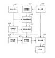
図1は本発明の実施の形態1のナビゲーション装置の一例を示すブロック図である。図において、1は車両の位置・運動状態を検出するセンサ群で、人工衛星からの電波信号を受信し車両の絶対位置を計測するGPS測位装置1a、車両の方位変化を計測するヨーレートセンサ1b、車両の走行速度を計測する車速センサ1c等からなる。
【0025】
2はセンサ群1で計測された車両の位置・運動状態から車両の走行位置を推定する自車位置推定手段、3は道路区間を所定の線分からなる道路リンクとこの道路リンクの始終点を表すノードとの組み合わせで定義される道路セグメントで表し、その集合体としての道路ネットワークを表現した地図データベース、4は自車位置推定手段2で推定された自車両の位置及びその時間履歴である走行軌跡と地図データベース3に記録された推定自車位置近傍の道路リンクデータ群とを比較し、自車両が走行している道路リンクを決定するとともに、決定された道路リンク上における自車両の位置を特定する道路照合手段である。
【0026】
6は道路属性に応じて走行特性を記憶した走行特性データベースで、ここで、道路属性は例えば高速道路、一般道路、主要国道、一般国道、地方道等の道路の種別や、13m以上、13m未満5.5m以上、5.5m未満等の道路の幅員等、道路の属性を表すものである。
【0027】
7は目的地の入力、地図のスクロール、経路探索の開始等、運転者の要求をナビゲーション装置へ入力するために用いるユーザーインターフェース手段で、一般にタッチパネルやリモコン等が用いられる。8はユーザーインターフェース手段7によって指定された目的地点と道路照合手段4によって特定された自車位置(自車位置を含む道路リンク)とを結ぶ経路を地図データベース3の道路ネットワークデータから検索し、この経路を道路リンクの集合体として記憶する経路探索手段である。
【0028】
9は経路探索手段8において計算された経路、即ち道路リンクの集合体について、この集合体を構成する道路リンクの属性及び総延長と、道路属性に対応する走行特性データベース6の走行特性とから経路全体を走行するのに要する所要時間を計算し、最適な経路を求めたり、現在時刻に前記所要時間を加算することで到着予想時刻を算出する誘導経路探索手段である。
【0029】
10は自車位置推定手段2で推定された自車両の位置と、この推定された自車両の位置周辺の所定範囲の道路ネットワークデータを地図データベース3から読み出し、運転者が自車両周辺の道路状況を理解できるように道路地図のような形態で表示する表示手段で、誘導経路探索手段9で設定された最適経路を前記形態の地図表示に重ねて強調する等の手法で表示すると共に、誘導経路探索手段9で算出された目的地までの所要時間もしくは、目的地への到着予想時刻等の表示を行う。
【0030】
さらに詳細に説明すれば、センサ群1は、地球を周回する複数の人工衛星から送出される電波信号を受信し、地球上の任意の地点の緯度経度および高度情報を得ることの出来るGPS測位装置1a、車両の旋回角速度、すなわち角度の変化分を計測するヨーレートセンサ1b、車両の走行速度、すなわち位置の変化分を計測する車速センサ1c等によって構成される。
【0031】
自車位置推定手段2は、ヨーレートセンサ1b及び車速センサ1cで計測された角度および位置の変化分を積算し、自律航法によって所定地点からの位置変化を算出するとともに、GPS測位装置1aで得られた車両の緯度経度情報と前記自律航法によって得られた位置情報とを比較参照することにより、車両が走行している位置の推定を行う。
【0032】
地図データベース3は、例えば図2(a)に示すような地図を、道路部について図2(b)に示すようなリンク(以下道路リンクと呼ぶ)とノードの集合体に分解し、道路ネットワークとして図2(c)のようなベクトル化表現に変換されたものが記憶されている。さらに、このようにべクトル化された道路ネットワークは、車両が走行する所定の区域を図3に示すようなメッシュ状の小区域に分割して管理されており、コンパクトディスク(CD−ROM)や光磁気ディスク(MO)、ハードディスク等に記録されている。
【0033】
図4は図2で説明した道路リンクのデータ構造を示す図で、図4(a)は道路リンクの一例、図4(b)は図4(a)で示した道路リンクのデータ構造の一例、そして、図4(c)はデータ構造中の道路属性データの構造の一例を示す図である。
道路リンクは、図4(a)に示すように通常両端が番号付きのノードNs、Neで規定され、このノードNs、Neを連結する線分にはリンク番号Lnが付される。この道路リンクは、一例として図4(b)に示すようなデータ構造で記録され、リンク番号Ln、始点、終点のノード番号Ns、Ne、始点、終点ノードの位置を表す座標Xs、Ys、Xe、Yeが記録されている。始点、終点の座標は、図3に示す細分化された区画の中で定義された数値(一般には正規化座標と称される。)でも良いし、緯度経度座標、その他の座標系を用いても良い。
【0034】
さらに、道路リンクの長さを表すリンク長L、この道路リンクの始点が接続している他のリンクのノード番号Ns−1、Ns+1、道路リンクの終点が接続している他のリンクのノード番号Ne−1、Ne+1、そして、図4(c)に示すようなこの道路の属性リスト等が記録される。
【0035】
道路属性リストは、一例として図4(c)に示したような情報で構成される。図4(c)の道路属性リストにおいては、一例として道路の種別として一般国道であることが記録され、この道路は40km/hが規制速度であり、55km/hが実勢速度、10mの幅員を持ち、車線数が2であり、一方通行の規制がなされていること等の道路属性が記録される。
【0036】
走行特性データベース6は、図5に示すように走行特性、この場合、各道路属性ごとに単位距離あたりに要する走行時間が記憶されている。この場合には、道路属性として図4(c)に示した道路属性リストにおける種別を用いたが、道路幅員等他の道路属性を用いてよいことは言うまでもない。
【0037】
経路探索手段8は、ユーザーインターフェース手段7によって目的地が設定されると、現在地と目的地周辺の道路ネットワークを地図データベース3から読み出し、さらに、目的地と現在地を結ぶ道路ネットワークを含む地図の区画を選定し、この区画に含まれる道路ネットワークを同じく地図データベース3から読み出す。
【0038】
表示手段10は、例えば液晶表示板等のグラフィクス表示素子を備え、地図データベース3に記録された道路ネットワークを地図として表示すると共に、自車位置推定手段2で検出された自車位置を表示し、さらに、ユーザーインターフェース手段7から経路探索の指示が入力されていた場合には経路探索手段8で得られた探索経路を前記地図に重ねあわせて表示するとともに、該探索経路について誘導経路探索手段9で算出された所要時間情報を画面の一部に表示する。
【0039】
次に、図1に示したナビゲーション装置の動作を説明する。まず、自車位置推定手段2において、センサ群1において計測された計測値に基づき、以下のようにして車両の推定位置を決定する。
図6は車両の位置の推定方法を説明する図である。図において、21は自律航法によって決定された推定位置、22はGPS測位装置によって得られた推定位置、23は推定自車位置、24は推定自車位置23の移動履歴すなわち走行軌跡である。25は走行道路リンク、26は同定された車両の現在地、27は道路リンクの分岐点、28は推定された走行軌跡の特徴点である。
【0040】
GPS側位装置1aで図6に示した推定位置22、ヨーレートセンサ1b及び車速センサ1c等を用いて自律航法によって図6に示した推定位置21をそれぞれ求める。一般に、自律航法では誤差の累積のために、GPS測位装置では信号伝播時の遅延や反射、意図的誤差の導入等の理由により両者は一致することが少ない。
そこで、センサ群1によって求められた推定位置21、22を按分もしくはその他のロジックによってハイブリッド処理を行うことにより、車両の推定自車位置23を決定する。
【0041】
次に、道路照合手段4において、推定自車位置23の位置座標を含む道路ネットワークを地図データベース3から呼び出すと共に推定自車位置23及び走行軌跡24との位置、進行方位等のパラメータについての相関を求め、車両が現在走行している道路リンク及び過去に走行していた道路リンクからなる走行道路リンク25を決定する。
そして、車両の走行軌跡24と走行道路リンク25を比較して、最終的に車両の現在位置26を同定する。この同定方法は、例えば、交差点を表すノード27のような特徴形状に対応する特徴点(この場合28)を走行軌跡の中から検出し、交差点27と特徴点28の位置差分を用いて推定自車位置23を修正することで決定される。
【0042】
一方、ユーザーインターフェース手段7において、運転者から経路探索の要求が生じた場合には、経路探索手段8において、自車位置と目的地点とを結合した経路を地図データベース3から検索し、この経路を道路リンクの集合体として記憶する。
【0043】
次に、誘導経路探索手段9において、式(1)を用いて所要時間TSGを算出する。
【0044】
【数1】
まず、経路探索手段8で設定された出発地から目的地までの経路を構成する道路リンクに対して、各道路属性ごとの道路の距離の和を求める。そして、この道路属性ごとの距離の和と、図5に示したような、その道路属性に対応した単位距離あたりの走行時間とを乗じて道路属性ごとの所要時間を算出する。最後に、これら各道路属性ごとの所要時間の和を求めることで、所要時間TSGを算出する。そして、この算出された所用時間TSGに基づいて最適な経路を決定し、この最適な経路を表示手段10によってディスプレー上に表示する。
【0046】
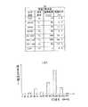
具体例を図7を用いて説明する。
図7は、経路探索手段8において設定された経路の一例で、図において、Sは経路探索の出発地、Gは目的地で経路探索の終了地点、そして、図中の区間表示はそれぞれの道路の属性を示す。図8は図7に示した経路に関するデータを示したものである。
【0047】
図9は経路探索手段における動作の一例を示したもので、図において、31〜33は道路ネットワークデータ、[S]は探索の開始点で、多くの場合車両の現在位置である。[G]はユーザーインターフェース手段7によって指定された目的地である。
【0048】
まず、ユーザーインターフェース手段7によって目的地が設定され、探索の開始が指示されると、経路探索手段8は、図9に示すように、探索開始点周辺の所定区画の道路ネットワークデータ31及び目的地周辺の所定区画の道路ネットワーク32を地図データベース3から読み出す。さらに、探索開始点Sと目的地Gが同一の地図区画に存在しないときは、この両者の区画を含む上位の地図区画33を地図データベース3から読み出し、これらの道路ネットワークから、探索開始点Sと目的地点Gを結ぶ道路リンク列(31、32、33中の太線)を選定する。
【0049】
次に、図9に示したような経路が選定されると、探索経路に含まれる道路を道路属性別に分類し、同じ道路属性に属する道路の距離の総和である道路属性別距離を積算する。そして、各道路属性別距離と走行特性データベース6に記録された各道路属性別の走行特性とを乗算することにより各道路属性別の所要時間を算出する。そして、これらの各道路属性別の所要時間の和をとることにより、所要時間TSGを算出する。
例えば、図7に示したように道路属性が一般道の場合には、一般道の区分はLR5、1(7km)とLR5、2(13km)とが存在するのでこれらの和を算出し、一般道の属性別距離は20Kmとなる。
【0050】
そして、図8に示したように、一般道の属性に対する走行特性は0.02564h/kmであるので、一般道の区間を走行するのに要する時間は20×0.02564=0.51時間となる。
以下、各道路属性について同様の計算を繰り返し、これらの総和をとることにより出発地から目的地までの全区間を走行するのに必要な所要時間TSGを算出する。(この場合、3時間43分になる)
そして、この誘導経路探索手段9によって計算された時間に基づいて最適な経路を求め、これらを表示手段10によってディスプレー上に表示する。
【0051】
図10は表示の一例を示したもので、図において51は表示される地図、52は自車位置推定手段2で決定された自車両の位置の表示、53は経路探索手段8で設定された探索経路の表示であり、54は誘導経路探索手段9で決定された目的までの道のりと所要時間の表示である。
ここでは、表示手段10として液晶表示板としたが、グラフィクス表示の可能なCRTやプラズマディスプレイ、その他のデバイスを用いても良いし、ドットマトリクスディスプレイなど文字を中心とする表示装置に所要時間を表示するようにしても良い。
【0052】
本実施の形態では、道路属性情報は道路の種別や道路の幅員等であるが、これらに加えて時間毎あるいは天候毎に道路属性情報を区分してよいことは言うまでもない。
【0053】
本実施の形態では走行特性データベースに記憶させている特性データは単位距離あたりの時間データであるが、これは特に限定するものではなく、時間データの替わりに速度データを用いてもよい。
この場合、式(1)により所要時間TSGを算出する替わりに、次式を用いて所要時間TSGを算出する。
【0054】
【数2】
さらに、本実施の形態では走行特性データベースに記憶させている特性データは道路属性ごとに記憶させているが、これは特に限定するものではなく、各運転者ごと、あるいは、これらの組み合わせで分類して記憶させてもよい。
【0056】
本実施の形態では、道路リンクの走行特性を各道路リンクごとに記憶させるのではなく、道路リンクの属する道路属性ごとに記憶しているので、1度も走行したことのない道路リンクを走行する場合においても、その道路リンクの所要時間が実走行によって求められていなくても、同じ属性の走行データによる実走行のデータが反映され、個々の運転者の嗜好を考慮した所要時間を求められ、正確な所要時間を求めることができる。
すなわち、未知の地点(初めて行く地点)を目的地に設定した際の誘導においても、個人特性が反映され、正確な所要時間が得られる。
【0057】
また、各運転者の特性毎に走行特性が利用されるので、同じ車両を異なる運転者が利用した場合にでも、各運転者の特性を反映した正確な所用時間予測が可能となる。
【0058】
実施の形態2.
図11は本発明の実施の形態2のナビゲーション装置を示す図である。図において、5は道路照合手段4で決定された道路リンクに付随して記録されている道路の属性を表す道路属性を抽出する道路属性抽出手段、6は道路属性に応じた走行特性(単位距離あたりの走行時間)及び走行特性を修正するため、各属性ごとの時間テーブルを記憶した走行特性データベースである。
【0059】
11はセンサ群1において計測された計測値に基づいて自車位置推定手段2で求められた運動状況と道路属性抽出手段5で抽出された走行中の道路リンクの属性値とから走行特性データベース6に記憶されている走行特性のデータを修正する走行特性学習手段である。その他は実施の形態1の図1で説明したものと同じであるので説明は省略する。
【0060】
図12は属性が高速自動車道である場合の時間テーブルである高速自動車道時間テーブルを例示したものである。高速自動車道時間テーブルは積算時間と積算された走行距離から構成され、積算時間は今までの走行時間を積算したもので、走行距離は走行時間内に走行した走行距離を今までの走行距離に新たに積算したもである。なお、ここでは属性が高速自動車道の場合を説明しているが、他の道路属性に関しても同様な構成になっている。
【0061】
本実施の形態では、走行特性学習手段11において走行特性のデータを修正すること以外は実施の形態1と同様であるのでその他の説明は省略する。
【0062】
図13は図11に示したナビゲーション装置の走行特性学習手段11の処理内容を示したフローチャート図である。なお、本処理は所定のタイミングで起動される。
まず、道路属性抽出手段5で検出された走行中の道路の属性を入力する。(S101)
次に、自車位置推定手段2において求められた車両の運転状況の情報に基づいて道路の走行に要した所要時間及び走行距離を入力する。(S102)
【0063】
そして、S101で入力した道路属性の属性を判定し、走行中の道路属性に応じてS104で処理するプロセスを切り替える。(S103)
次に、S103で判定された道路属性毎に、走行した時間の積算値及び走行距離を新たに加算し、走行特性を更新する。(S104)
本実施の形態では、S104で処理する道路の属性の例として、高速自動車道、自動車専用道、主要国道、一般国道、主要地方道、一般道の6種別に分類した場合を示す。
【0064】
次に、S104で積算した走行時間と走行距離との関係から、各道路属性毎の走行特性値として平均的な単位距離あたりの走行時間(走行特性)を算出する。(S105)
そして、S107によって算出された最新の走行特性値によって走行特性データベース6の走行特性値を更新する。(S106)
最後に、次回の学習処理に備え、走行積算時間タイマの初期化を実施し、本処理を終了する。(S107)
【0065】
なお、これらの学習処理は実施の形態1で説明したような経路探索を行っている状態で行われてもよいし、また、経路探索が行われていない状態で上記の学習のみを行わせるようにしてもよい。
【0066】
本実施の形態では、道路属性毎に識別して記憶されているが、走行特性データベース6に記憶される走行特性の情報は走行特性学習手段11によって学習された情報を各運転者毎に識別して記憶させてもよいし、あらかじめ算出しておいた各運転者の走行特性を例えばカード等に記憶させておき、このカードの情報を走行特性データベースに読みこんでもよい。
【0067】
本実施の形態2のナビゲーション装置においては、運転者の走行特性を、走行している道路の属性別に学習することにより修正するので、運転者の走行に応じて走行特性が修正され、より個々人の特性を反映した正確な所要時間予測が可能となる。
また、経路探索が行われていない無誘導の走行時の走行特性をも考慮しているので、経路探索を行っていない通常の無誘導の状態での走行速度の嗜好をも反映することができる。
【0068】
実施の形態3.
本発明の実施の形態3は、実施の形態2の図11に示したナビゲーション装置における走行特性データベースの走行特性を図5に示したような単位距離当たりの走行時間ではなく、速度にしたものである。
【0069】
図14は本実施の形態の走行特性データベースに記憶される走行特性(速度)及び走行特性を修正するため、各属性ごとの時間テーブルを示した図で、図14(a)は走行特性を図14(b)は走行特性を修正するための時間テーブルの一例、そして、図14(c)は走行速度と積算走行時間との関係を示している。
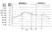
本実施の形態の走行特性は、図14(a)に示すように、走行特性が道路属性ごとに区分された速度で表されている。また、時間テーブルは、速度属性値と積算時間及び時間比率の関係を示したもので、例えば、道路属性が高速自動車道である場合には、図14(b)に示すように、走行速度に応じて複数の速度属性で区分し、この区分された速度属性ごとに積算時間が求められ、さらに、全速度属性に対して各速度属性が占める時間比率を示している。
【0070】
そして、積算時間は、速度属性値及び道路属性値が変更となるたびに、所定時間を積算することにより求められる。
図14に示した例では、高速自動車道の積算走行時間は走行速度100〜120km/hでの走行が最も多く、言い換えればこの運転者は高速自動車道の走行においては、この速度帯を好んで用いて走行していることが分かる。
なお、これらの時間テーブルは道路属性と同数のテーブルで構成される。
【0071】
本実施の形態では、走行特性を速度にしたことに伴い、図11に示した走行特性学習手段11は、道路属性抽出手段5で抽出された走行中の道路属性と、自車位置推定手段2で求められた車両の走行速度とを関連付けて頻度を学習し、各道路属性毎の走行特性を決定する。そして、学習された道路リンクの各属性に対する走行特性を走行特性データベース6に記憶する。
【0072】
同様に、誘導経路探索手段9においても、実施の形態2のように式(1)からではなく、実施の形態1で示した式(2)を用いて所要時間TSGを算出するようにする。
【0073】
図15は走行特性学習手段11の処理内容を示したフローチャート図である。なお、本拠理は所定のタイミングで起動される。
まず、道路属性抽出手段5で検出された走行中の道路の属性を入力する。(S201)
次に、自車位置推定手段2で求められた車両の走行速度を入力する。(S202)
そして、S202で求められた走行速度に基づき、現在走行している車両の速度が属している速度属性を決定する。(S203)
【0074】
次に、走行特性学習の処理において、前回検出された走行速度の属性と、現在検出された速度の属性との比較を行う。比較の結果、速度属性が変化していればS206を実行し、速度属性の変化が無ければS205を実行する。(S204)
S205では、S201で入力された走行中の道路の道路属性について、前回に走行特性学習の処理が起動されたときに走行していた道路の属性と現在検出している道路属性との比較を行い、道路属性の変化が無ければ、以降の処理は不要であるとして終了する。道路属性の変化が有ったと判定された場合には、S206へ移行する。
【0075】
S206では、S201で入力した道路属性の属性を判定し、走行中の道路の属性に応じてS207で処理するプロセスを切り替える。
S207では、S206で判定された道路属性毎に、S203で決定された速度属性値で走行した時間の積算値を更新する。
本実施の形態では、S207で処理する道路の属性の例として、高速自動車道、自動車専用道、主要国道、一般国道、主要地方道、一般道の6種別に分類した場合を示す。
【0076】
S208では、S207で積算された速度属性値と積算時間との関係から、各道路属性毎の走行特性値として平均的な走行速度を統計的手法を用いて算出する。この走行速度は、例えば、図14(b)のような走行速度頻度分布となった場合には、単純平均として95km/hを高速自動車道路における走行特性値とすればよい。あるいは、最多頻度値として速度属性V5(属性中央値110km/h)を高速自動車道路における走行特性値としてもよいし、その他の標準偏差計算などによって求めても良い。
【0077】
さらに、S209では、S208までの処理によって得た最新の走行特性値によって走行特性データベース6を更新する。
S210では、上記までの処理で、速度属性値の変化及び道路属性値の変化に対応した走行特性の学習が完了したので、次回の学習処理に備え、走行積算時間タイマの初期化を実施し、本処理を終了する。
【0078】
図16は、S203の速度属性の決定、及び各速度属性における走行時間の算出についての説明図である。図16において、横軸は時間、縦軸は走行速度を表し、さらに速度属性の例として、走行速度を20km/hおき、すなわち20km/h未満、20km/h以上40km/h未満、のように範囲を設定し、車両の走行速度が含まれる所定範囲をその状態での速度属性とする。
速度属性毎の走行時間は、車両の走行速度が所定属性の速度範囲(例えば、速度属性V5)に入った時点(図16のa点)から該属性の速度範囲から逸脱した時点(図16のb点)までの経過時間ΔTをタイマ(図示していない)によって計測する。
【0079】
また、同一速度属性内であっても、走行している道路属性が変化した際には、経過時間の計測を道路属性が変化した時点で終了し(図16のc点)、新規道路属性(例えば、R1)についての経過時間計測を開始する。以後、R1属性の道路が継続した場合、速度属性の変化点(図16のd点)で該速度属性(例えば、V4)の経過時間計測を終了する。
【0080】
このような動作の具体例を図7を用いて説明する。
図17は図7に示した経路に関するデータを示したものである。
まず、図7の探索経路に含まれる道路を道路属性別に分類し、道路属性別距離を積算する。次に、各道路属性別距離を走行特性データベース6に記録された各道路属性別の走行特性(速度)によって除算することにより各道路属性別の所要時間を算出し、これらの所要時間の総和をとることにより所要時間TSGを算出する。例えば、図7に示した高速自動車道の属性別距離は120Km(LR0,1)であり、高速自動車道属性に対する走行特性は95Km/hであるので、高速自動車道の区間を走行するのに要する時間は120/95=1.26時間となる。
以下、各道路属性について同様の計算を繰り返し、これらの総和を求めることにより、出発地から目的地までの全区間を走行するのに必要な所要時間TSGを算出する。
その他は、実施の形態2で説明したものと同様であるので説明は省略する。
【0081】
本実施の形態のナビゲーション装置においては、通常の走行状態において車両の走行速度すなわち運転者の走行特性を、走行している道路の属性別に学習することにより修正するので、運転者の走行に応じて走行特性が修正され、より個々人の特性を反映した正確な所要時間予測が可能となる。
【0082】
実施の形態4.
本発明の他の実施の形態について説明する。実施の形態3が図14(b)に示したように積算時間に基づいて走行特性を修正させているのに対し、本実施の形態では、積算時間の代わりに積算距離を用い、これらによって走行特性を修正させる。その他の動作については、実施の形態3とすべて同一であるので説明を省略する。
図18は本発明の実施の形態4の走行特性学習手段11における処理のフローチャートを示した図である。
図18における、S301、S302は実施の形態3の図15のS201、S202と同様であるので説明を省略する。
【0083】
図19は本実施の形態4における走行特性学習手段11におけるS303の速度属性の決定及び各速度属性における走行距離算出についての説明図である。図19において、横軸は走行距離、縦軸は走行速度を表す以外は実施の形態3の図16と同様である。速度属性毎の走行距離は、車両の走行速度が所定属性の速度範囲(例えば、速度属性V5)に入った時点(図19のa点)から該属性の速度範囲から逸脱した地点(図19のb点)までの走行距離ΔLを走行距離レジスタ(図示しない)によって計測する。
【0084】
また、同一速度属性内であっても、走行している道路属性が変化した際には、距離の計測を道路属性が変化した時点で終了し(図19のc点)、新規道路属性(例えば、R1)についての経過時間計測を開始する。以後、R1属性の道路が継続した場合、速度属性の変化点(図19のd点)で該速度属性(例えば、V4)の経過時間計測を終了する。
以下、S304からS309について内部処理の相違点についてのみ説明する。
【0085】
図20は図18におけるS306の高速自動車道速度テーブルについての例を示したものである。図20(a)は速度属性値と積算走行距離及び距離比率の関係を示したもので、積算走行距離は速度属性値及び道路属性値が変更となるたびに、S303の処理で求めた走行距離ΔLを積算することにより求める。
図20に示した例では高速自動車道の積算走行距離は、走行速度100〜120km/hでの走行が最も多く、この速度帯を好んで用いることが分かる。
【0086】
本実施の形態と実施の形態1との相違点は、時間ベースで計算する場合には、低速で走行するほど経過時間が長くなり、低速の速度帯に重み付けした特性算出が行われることになるのに対し、距離ベースの場合には、低速から高速まで均等の重み付けとなる点にある。
【0087】
図21は上記相違点の説明図である。例えば、図21(a)に示すような100kmの区間について、80kmの距離を90km/hで自由に走行し、残り20kmを他車に追従しながら50km/hの速度で走行したとすると、この場合の速度テーブルは図21(b)となる。
上記の条件について走行特性を時間ベースで計算すると、速度属性V2が31%、速度属性V4が69%となるのに対し、距離ベースで計算するとそれぞれ、20%、80%となる。すなわち、時間ベースでは低速側に重みが付くことが解かる。そのため、自由な状態で走行した結果を良く反映できる後者の方が、個人の特性を反映するのに適していると考えられる。
【0088】
S310では、実施の形態3のS210と同様に、S301からS309までの処理で、速度属性値の変化及び道路属性値の変化に対応した走行特性の学習が完了したので、次回の学習処理に備え走行距離レジスタの初期化を実施し、本処理を終了する。
【0089】
本実施の形態のナビゲーション装置においては、通常の走行状態における個々の運転者の走行特性の学習において、走行特性の学習をその走行速度属性で走行した距離を積算して計算し、これを道路属性別の走行特性データベースとして記憶するので、実施の形態3に加え、より個々人の特性を反映した正確な所要時間予測が可能となる。
【0090】
実施の形態5.
図22は本発明の実施の形態5のナビゲーション装置の構成を示す図である。図において、6は実施の形態3の図11に示したナビゲーション装置における動作に加え、休憩特性学習手段13によって学習された運転者の休憩取得の特性をデータベースとして記憶する走行特性データベースである。
【0091】
9は図11のナビゲーション装置における動作に加え、走行特性データベース6に記録されている休憩取得の特性から探索された経路を走行する際に取得するべき休憩の回数を計算すると共に、所要時間計算の際に、休憩の回数と休憩に要する時間を考慮して総所要時間を計算する誘導経路探索手段である。
【0092】
10は地図や探索経路の表示に加え、目的地までの道のり、所要時間、推奨休憩時刻などを表示する表示手段、12は自車位置推定手段2及び道路照合手段4の情報を用いて車両の走行状態から休憩状況を判定する休憩判定手段、13は休憩判定手段12で得られた休憩状況を入力し、運転者の休憩特性を学習する休憩特性学習手段である。その他は、実施の形態3の図11で説明したナビゲーション装置の動作と同一であるので説明を省略する。
【0093】
次に、本実施の形態の動作を説明する。本実施の形態は、休憩特性を利用すること以外は実施の形態3と同様であるので、その他の説明は省略する。
休憩判定手段12において判定された結果に基づいて、休憩特性学習手段13において走行特性データベースの休憩特性を学習し、誘導経路探索手段において、これらの特性値によって経路探索を行う方法を説明する。
【0094】
まず、休憩判定手段12において、自車位置推定手段2で計測されている車両の運動状態と道路照合手段4で判定された道路との位置関係から車両が現在道路リンク上に存在するか否かを判定することにより、運転者が休憩の状態にあるか否かを推定する。
【0095】
次に、休憩特性学習手段13において、休憩判定手段12で判定された休憩状態と休憩時間情報から個々の運転者の休憩取得の特性を学習する。ここで、休憩取得の特性としては、例えば、車両が継続して走行している走行継続時間、休憩を行っている休憩取得時間等が挙げられる。
図23は休憩取得特性の概要の説明図であり、図において、横軸は時間、縦軸は車速であり、図中の曲線は車両の走行速度パターンを示している。
まず、休憩取得特性は走行を開始してから休憩を開始するまでの走行継続時間Trunと、休憩を開始してから走行を再開するまでの休憩取得時間Trestを計測する。そして、これらの計測値を統計的に処理することにより休憩取得特性を決定し、走行特性データベース6に記録する。
【0096】
そして、誘導経路探索手段9において、以下のように所要時間を算出する。
図24は誘導時間探索手段9における所要時間算出の例を示す図である。図において図24(a)は本実施の形態における走行特性データベース6の一例であり、実施の形態3、4における走行特性データベースに休憩取得特性を追加したものである。図24(a)の場合、この運転者の平均的な走行継続時間は1時間20分であり、また平均的に15分の休憩を取得したことを表している。
【0097】
図24(b)は本実施の形態における所要時間計算での計算結果を示したもので、所要時間計算対象の探索経路及びその他の条件は実施の形態3における所要時間計算例と同一のものである。
全区間の道路距離と道路属性別の走行特性から実施の形態3で説明したように所要時間を計算すると3時間43分が必要となる。
【0098】
また、この運転者の走行特性データベースに記録された平均走行継続時間は1時間20分であるので、本区間はこの運転者の走行特性に合致するよう、図24(b)に示すように3つの区間に分割して走行することが望ましい。
そして、以上のように分割して走行するためには、一回の休憩に付き15分を要するので、結局、この運転者の場合は、この区間を走行する所要時間は、3時間43分に休憩時間の30分を加算した4時間13分を要することになる。
【0099】
図25は休憩判定手段12の処理の一例を示した図である。なお、本処理は所定のタイミングによって起動される。
以下に処理の内容を説明する。
まず、自車位置推定手段2から車両の移動速度を代表とする車両の運動状態を入力する。(S401)
次に、道路照合手段4から道路との照合状態すなわち現在の自車両の位置と道路リンクとの位置関係を入力する。(S402)
【0100】
そして、S402で入力された道路照合状態について、車両が現在道路リンク上に存在するか否かに付いて判定を行う。道路上と判定されれば、以下の処理を省略して本処理を終了する。道路外すなわち、道路リンクから離れて何らかの施設内や駐車場内などに車両が存在すれば、休憩の可能性があるとしてS404を実行する。(S403)
S404ではS401で入力された車両の運動状態から、車両が走行中か否かを判定する。走行中と判定されれば、車両が地図データベースに記録されていない道路を走行中もしくは道路外の走行中であるか、あるいは、休憩後の走行再開であるかを判定するためにS408を実行する。また停止中であると判定されれば、S405を実行する。
【0101】
S405では、本処理が起動されてから初めての休憩候補状態であるかを判断するために、休憩判定フラッグを検査する。休憩判定フラッグが設定済みであれば、すでに休憩候補の状態にあるとして以下の処理を省略し、本処理を終了する。休憩判定フラッグが未設定であれば、初めての休憩候補状態であるとし、S406を実行する。
S406では、これまでの処理により、休憩候補状態にあると判定されたので、休憩時間の計測を開始するために、タイマを起動し、S407で休憩候補の初期の状態にあることを記憶するための休憩判定フラッグを設定する。
【0102】
S408では、休憩判定フラッグを検査し、フラッグが未設定であれば道路外、データ外道路を走行中であると判断し、本処理を終了する。フラッグが設定済みであれば、休憩後の走行開始であると判断し、S409を実行する。
S409では、S406で開始したタイマから休憩時間を計測しタイマを初期化する。S410では次の休憩判定に備え、休憩判定フラッグを解除する。
【0103】
本実施の形態のナビゲーション装置は、継続的に走行する時間と休憩に要する時間とを学習し、これを走行特性データベースに休憩取得特性として記憶するよう構成し、出発地から目的地にいたる探索経路の走行に要する所要時間の算出を、個々の運転者の通常の走行特性を反映して所要時間算出を行い、かつ、所要時間中に含まれるべき休憩時間を考慮して所要時間算出を行うように構成されているので、休憩時間の取得を加味した余裕のある所要時間計算が行え、個々人の特性を反映した正確な所要時間予測が可能となると共に適切な休憩時期を運転者に提案することができ、安全性向上にも寄与することが可能となる。
【0104】
また、本実施の形態においては、実施の形態3と同様に時間を特性の基準として走行特性の学習を行っているが、これを実施の形態4と同様に距離を特性の基準として走行特性の学習を行っても良い。この場合、より運転者の走行特性を正確に規定できる利点があると共に、全経路と対比させてどの地点で休憩を取るべきかが概略判定できる利点がある。
【0105】
実施の形態6.
実施の形態5における休憩判定手段12は、道路外走行における停止と再出発の状態判定のみで休憩時間の判定を行うよう構成されているが、本実施の形態では、これに加えて休憩時間の長短に応じて休憩か否かを判断するようにさせる。その他は実施の形態5と同様であるので説明は省略する。
【0106】
図26は本実施の形態における休憩判定手段12の処理を示すフローチャート図である。
図26において、S501からS510の動作は実施の形態5の図25のS401からS410と同一であるので詳細な説明は省略する。
S511では、あらかじめ規定された休憩時間の所定値と、S509で計測された休憩時間との比較を行い適合性の判定を行う。例えば、計測された休憩時間が所定値より短く、休憩とは判断できない場合には不適合とし、S512にて今回計測した休憩時間データを破棄しS510を実行する。計測された休憩時間が所定値より長く休憩の条件に適合した場合は、S510で次回計測に備え休憩判定フラッグを解除して本処理を終了する。
【0107】
前記のように構成されたナビゲーション装置においては、わずかな寄り道や、自動販売機等でのわずかな停止などに左右されずに休憩時間の計測を行うことが可能となり、走行特性の学習精度を向上することが可能となる。
【0108】
さらに、ユーザーインターフェース手段において、自宅位置や目的地の位置を設定し、この設定された自宅位置もしくは目的地の位置情報と、自車位置推定手段で計測された車両の位置情報を利用し、休憩と自宅での駐車や目的地での駐車を明確に区別できるように構成すれば、より学習の精度が向上する。
【0109】
また、日常の買い物など、ごく短距離の移動を多用した場合には、走行特性データベースの平均走行継続時間もしくは平均走行継続距離が本来の特性値よりも小さくなることが予測される。そこで、このような不具合を避けるために、休憩時間の学習を経路探索が実施された場合にのみ実行するように構成しても良い。
【0110】
実施の形態7.
図27は本発明の実施の形態7のナビゲーション装置を示す図である。図において、10は実施の形態5の動作に加え、探索経路上に設定された推奨休憩地点を地図表示の際に、重ねあわせて表示する表示手段である。
14は走行特性データベース6に記録された休憩取得特性と道路属性別の走行特性とを用いて、経路探索手段8で計算した所定地間の探索経路から推奨休憩地点を算出する休憩推奨地点設定手段である。その他は実施の形態5と同一であるので、説明を省略する。
【0111】
次に、本実施の形態の動作について説明する。本実施の形態においては、休憩推奨地点設定手段14において休憩推奨地点を求め、表示手段10において、この休憩推奨地点を表示させること以外は実施の形態5と同様であるのでその他の説明は省略する。休憩推奨地点設定手段14の動作に付いて説明する。
【0112】
休憩推奨地点設定手段14は、出発地から目的地までの順次設定された経路について道路属性と該道路属性の距離を経路探索手段8から入力する。さらに、該道路属性についての走行特性を走行特性データベース6より入力し、該道路属性の区間を走行するのに要する時間と出発地からの積算時間を計算する。例えば、図7に示すような経路の場合には図28(a)のようなデータが得られる。
【0113】
図28(a)において、1行目は出発地からの特定属性の区間を表す区間番号、2行目は該各区間の道路属性、3行目は該区間の区間距離であり、これらのデータは、経路探索手段8での探索経路情報から得られる。
4行目は走行特性データベース6より入力された各道路属性毎の走行特性(具体的には走行速度)である。
5行目は各区間を走行するのに要する区間走行時間で、経路探索手段8で得られた区間距離を走行特性データベース6に記録されている走行特性値で除算することにより求めることができる。6行目は所要時間予測に用いる累積走行時間である。
【0114】
次に、休憩推奨地点設定手段16における休憩推奨地点の算出方法について説明する。
図28(b)において、区間距離、区間走行時間、探索経路については図28(a)と同様である。探索された経路について、走行特性データベース6に記録された休憩取得特性(連続走行時間Trun)を用いて、休憩の推奨地点を経路中から決定する。すなわち、最初の休憩地点については、出発地からTrun時間が経過したときに車両が存在する地点を道路属性別の区間距離及び走行特性値を用いて計算し、この地点を第1の休憩推奨地点とする。次に、第1の休憩推奨地点を起点とし、この地点からさらにTrun時間が経過したときに車両が存在する地点を計算し、この地点を第2の休憩推奨地点とする。そして、同様にして休憩推奨地点を求めていき、これを全経路が含まれるまで繰り返し、休憩推奨地点を設定する。
【0115】
図29は休憩推奨地点設定手段14で設定された休憩推奨地点を、算出に用いた道路ネットワークに対比させて示したものであり、図中R印は休憩推奨地点を示す。
図30は表示手段10における休憩推奨地点の表示の一例であり、図において、52は車両の現在位置、53は計算された目的地までの探索経路の表示、そして、55は休憩推奨地点設定手段において求められた休憩推奨地点である。
【0116】
本実施の形態のナビゲーション装置においては、休憩の取得を所要時間にのみ反映させるのではなく、探索経路及び走行特性と組み合わせて休憩推奨地点を計算し地図上に表示させるので、適切な休憩の位置を認識できることにより、休憩をとるべきタイミングをより視覚的に運転者に伝えることが可能となり、走行の安全性に貢献することが可能となる。
【0117】
また、本実施の形態において、休憩特性学習手段13及び走行特性データベース6の形態として、実施の形態4記載の距離を特性の基準として休憩推奨地点を計算するように構成しても良い。
【0118】
図31は距離を特性の基準とした場合の休憩推奨地点の算出方法についての概念図である。図31において、区間距離、区間走行時間、探索経路については図28(b)と同様である。探索された経路について、走行特性データベース6に記録された休憩取得特性(連続走行距離Lrun)を用いて、休憩の推奨地点を経路中から決定する。すなわち、最初の休憩地点については、出発地からLrunの距離だけ離れた地点を第1の休憩推奨地点とする。次に、第1の休憩推奨地点を起点とし、この地点からさらにLrunの距離だけ離れた地点を第2の休憩推奨地点とする。そして、同様にして休憩推奨地点を求めていき、これを全経路が含まれるまで繰り返し、休憩推奨地点を設定する。
【0119】
図28(b)で説明した場合には、地点を算出する際に、連続走行時間Trunと走行特性値を用いて距離を算出し、探索経路の区間距離との大小関係を考慮しながら地点計算を行ったが、距離を特性の基準とした場合には、出発地から順次連続走行距離Lrunで区間を分割していくことで地点計算が可能となる。
このように、距離を特性の基準とすることにより、休憩推奨地点の計算は連続走行時間ではなく、連続走行距離Lrunを用いるため地点計算が容易になり、休憩推奨地点算出の計算機負荷が少なくなる利点も発生する。
【0120】
実施の形態8.
図32は本発明の実施の形態8のナビゲーション装置全体の構成を示す図である。図において、15は地図データベース3に記録された各種施設の情報と休憩推奨地点設定手段14で設定された休憩推奨地点の位置情報とから休憩推奨地点近傍の休憩可能な施設を検索し、施設情報を表示手段10に出力する周辺施設検索手段である。その他は実施の形態7と同一であるので、説明を省略する。
【0121】
図33は本実施の形態8における表示手段10で表示される休憩推奨地点R55及び周辺施設検索手段15で検索された地点R近傍の休憩可能施設の表示を示す図である。
図34は図33で示された地点R近傍の近傍休憩可能施設の検索の概念図である。図34において、R点は休憩推奨地点設定手段14で設定された休憩推奨地点であり、その周辺の△印及び◇印は、地図データベースに記憶されている周辺施設の位置情報および施設名称である。
周辺施設検索手段15は、休憩推奨地点Rと周辺の施設との距離があらかじめ定められた所定値以下か否かを判定し、所定値以下であれば、休憩推奨地点近傍の休憩可能施設であるとして、その位置情報と施設種別を表示手段10に出力する。
【0122】
図34に示した例では、所定値以下(所定半径内)にレストランA、D、喫茶Bが存在するので、図33に示すように、これらの位置と施設種別が表示手段10によって表示される。
図33に示すように、表示手段10は周辺施設検索手段15の出力を受けて、これまでの実施の形態と同様に地図上に自車位置52、探索経路53、休憩推奨地点54を表示するとともに、周辺休憩可能施設56の位置を表示する。
【0123】
本実施の形態のナビゲーション装置においては、休憩推奨地点近傍に存在する休憩可能な施設を地図データベースより検索し、地図上に表示するので、実際に休憩をとることが可能な休憩場所を視覚的に運転者に伝えることが可能となり、不案内な土地においても迷うことなく休憩を取得可能であり、走行の安全性に貢献することが可能となる。
【0124】
実施の形態9.
図35は本発明の実施の形態9のナビゲーション装置全体の構成を示す図である。図において、7は表示手段10に示された施設情報リストの選択および休憩地点設定に関する運転者の選択内容を経路探索手段8に出力するユーザーインターフェース手段である。
15は地図データベース3に記録された各種施設の情報と休憩推奨地点設定手段14で設定された休憩推奨地点の位置情報とから休憩推奨地点近傍の休憩可能な施設を検索し、施設情報リストおよび休憩地点設定を即す画面を表示手段10に出力する周辺施設検索手段である。
その他は実施の形態8と同一であるので説明を省略する。
【0125】
本実施の形態の動作を説明する。本実施の形態では、誘導経路を求める場合に、休憩推奨地点を考慮に入れて誘導経路を求める。誘導経路の探索方法以外は実施の形態8と同様であるのでその他の説明は省略する。
【0126】
まず、経路探索手段8において、ユーザーインターフェース手段7で選択された休憩地点の設定に関わる情報を入力すると共に、周辺検索手段15で検索された休憩可能な施設についての地点情報を入力し、所定地点間の探索を行う際に、前記選択された休憩可能施設を経由地として最適経路の探索を実施する。
【0127】
図36は実施の形態9における表示手段10の休憩推奨地点選択の表示の一例である。周辺検索手段15は、前記実施の形態8の動作と同様にして休憩推奨地点近傍の休憩可能施設を検索し各休憩推奨地点毎に休憩可能な施設のリストを作成する。
表示手段10は、周辺検索手段15で作成された施設リストに従い、休憩可能施設を経由地に設定するか否かの選択、リストからの施設の表示と選択、選択された施設の施設情報の表示、設定の実行などを促する画面を作成し表示を行う。ユーザーインターフェース手段7は、表示手段10で表示されたりストおよび設定内容などの運転者の操作内容を入力し、経路探索手段8に経由地設定の有無、設定された休憩施設の位置情報を順次出力する。
【0128】
経路探索手段8は、ユーザーインターフェース手段7によって経由地設定が指示されたか否かを判定し、休憩可能施設が経由地に設定されていなければ通常の探索を実施し、休憩可能施設が経由地に設定されていれば設定されたすべての休憩可能施設について位置情報を周辺施設検索手段15から入力する。
さらに、経路探索手段8はこれらの周辺施設の位置を経路に含むように所定地点間の経路探索を実施する。
探索された最適経路は、前記実施の形態と同様に表示手段10によって地図とともに表示され、かつ運転者への誘導を行う。
【0129】
図37は本実施の形態9における表示の一例であり、実施の形態8の休憩推奨施設の候補のうちの一点(◇喫茶B)が選定された場合に、この選定施設が含む探索結果53が表示されることを示す。
また、本実施の形態の説明では一般道路の場合のみを図を用いて説明したが、高速道路などの自動車専用道路では、路線上のサービスエリアやパーキングエリアを優先して休憩可能施設とするよう構成しても良い。
【0130】
本実施の形態のナビゲーション装置においては、休憩の取得を所用時間にのみ反映するのではなく、探索経路および走行特性と組み合わせて休憩推奨地点を計算し、さらにこの休憩推奨地点の近傍に存在する休憩可能な施設を地図データベースより検索し所定地点を結ぶ探索経路に含まれるように経路を探索するように構成されるので、実際に休憩を取得して実走行をするとき実際の所要時間により近い所要時間を算出することができ、不案内な土地においても迷うことなく休憩を取得可能であり、かつ地図を見なくても的確に休憩地点に誘導されるため、利便性ならびに走行の安全性の向上に貢献することが可能となる。
【0131】
また、実施の形態5〜9においては、図24に示したように、道路属性毎ではない平均走行継続時間及び平均休憩時間を求めているが、実施の形態1〜4において説明した走行特性と同様に考えて平均走行継続時間及び平均休憩時間も各道路属性毎に求めてもよい。
【0132】
【発明の効果】
本発明に係るナビゲーション装置は、車両が道路セグメントからなる経路を走行するのに要する所用時間を道路セグメント情報と道路属性ごとに求められた走行情報とから算出し、この所要時間に基づいて車両を誘導する誘導経路を探索するので、1度も走行したことのない道路リンクを走行する場合や走行回数が少ない場合において、その道路リンクの所要時間を同じ属性の道路での実走行によって得られた情報によって求められ、個々の運転者の嗜好を考慮した所要時間を求められる。
【0133】
走行情報は、車両を運転する運転者ごとに区分されているので、同じ車両を異なる運転者が利用した場合にでも、各運転者の特性を反映した所要時間予測が可能となる。
【0134】
走行情報は、車両の速度分布であるので、1つの道路リンクに対し複数の速度属性に区分することができ、さまざまな手法を用いて各運転者の走行特性を求めることができる。
【0136】
車両の運動状態を計測する車両状況計測手段と、車両状況計測手段において計測された運動状態に基づいて、車両の走行情報を修正する走行特性学習手段とを備えているので、車両が走行することにより、走行情報を修正することができ、より個々の運転者の走行嗜好を反映した所要時間の算出が可能となり、所要時間予測の精度を向上する事が可能となる。
【0137】
道路セグメントと休憩取得情報とから車両を誘導する誘導経路を探索するので、所要時間の精度を向上し、かつ適宜の休憩を考慮する事により走行の安全性にも貢献できる。
【0139】
経路探索手段において、道路セグメントと休憩取得情報とから休憩取得地点を探索し、表示手段において、経路探索手段において探索された休暇取得地点を表示するので、休憩取得地点を運転者が認識することができ、休憩をとるべきタイミングをより視覚的に運転者に伝える事が可能となり、走行の安全性に貢献する事が可能となる。
【0140】
経路探索手段において、道路セグメント情報と休憩取得情報とから休憩取得地点近傍の休憩可能施設を探索し、表示手段において、経路探索手段において探索された休暇可能施設を表示するので、運転者は実際に休憩を取得できる場所が認識でき、不案内な土地においても迷うことなく休憩取得場所がわかり、走行の安全性に貢献する事が可能となる。
【0141】
経路探索手段において、道路セグメントと休憩取得情報とから休憩取得地点近傍の休憩可能施設を探索し、道路セグメントから車両を誘導する誘導経路に前記休憩可能施設を含むように誘導経路を探索するので、実際の休憩を含めた正確な所要時間がわかり、不案内な土地においても迷うことなく休憩を取得可能であり、かつ地図を見なくても的確に休憩地点に誘導されるため、利便性ならびに走行の安全性の向上に貢献する事が可能となる。
【0142】
車両の運動状態を計測する車両状況計測手段と、車両状況計測手段において計測された運動状態に基づいて、休憩取得特性データベースに記憶されている休憩取得情報を修正する休憩取得特性学習手段とを備えているので、車両が走行することにより、休憩取得特性を修正することができ、より個々の運転者の走行嗜好を反映した所要時間の算出が可能となり、所要時間予測の精度を向上する事が可能となる。
【0143】
車両状況計測手段は、経路探索を行わない無誘導の状態での走行時の車両の運動状態を計測し、学習手段は、無誘導の状態で計測された運動状態に基づいて情報を修正するので、無誘導の状態で走行している場合の走行速度の嗜好をも反映させることができる。
【図面の簡単な説明】
【図1】 本発明の実施の形態1のナビゲーション装置を示す図である。
【図2】 道路ネットワーク表現の説明図である。
【図3】 地図管理法の説明図である。
【図4】 道路ネットワークの記述例の説明図である。
【図5】 本発明の実施の形態1の走行特性を示した図である。
【図6】 自車位置推定手段および道路照合手段の動作の説明図である。
【図7】 本発明の実施の形態1の所要時間算出例の説明図である。
【図8】 本発明の実施の形態1の所要時間算出例の説明図である。
【図9】 図1の経路探索手段の動作の説明図である。
【図10】 本発明の実施の形態1の表示の一例を示す図である。
【図11】 本発明の実施の形態2のナビゲーション装置を示す図である。
【図12】 本発明の実施の形態2の時間テーブルを示す図である。
【図13】 本発明の実施の形態2のフローチャート図である。
【図14】 本発明の実施の形態3の走行特性例の説明図である。
【図15】 本発明の実施の形態3のフローチャート図である。
【図16】 実施の形態3の走行特性学習手段の動作の説明図である。
【図17】 図7に示した経路に対するデータを示す図である。
【図18】 本発明の実施の形態4のフローチャート図である。
【図19】 実施の形態4の走行特性学習手段の動作の説明図である。
【図20】 本発明の実施の形態4の時間テーブルを示す図である。
【図21】 本発明の実施の形態4の走行特性算出の説明図である。
【図22】 本発明の実施の形態5のナビゲーション装置を示す図である。
【図23】 図22の休憩判定手段の動作の説明図である。
【図24】 本発明の実施の形態5の所要時間算出の説明図である。
【図25】 本発明の実施の形態5のフローチャート図である。
【図26】 本発明の実施の形態6のフローチャート図である。
【図27】 本発明の実施の形態7のナビゲーション装置を示す図である。
【図28】 本発明の実施の形態7の休憩推奨地点算出の説明図である。
【図29】 本発明の実施の形態7の休憩推奨地点の概念図である。
【図30】 本発明の実施の形態7の休憩推奨地点の表示例を示す図である。
【図31】 本発明の実施の形態7の休憩推奨地点算出の説明図である。
【図32】 本発明の実施の形態8のナビゲーション装置を示す図である。
【図33】 本発明の実施の形態8の休憩可能施設表示の概念図である。
【図34】 図32の周辺施設検索手段の動作の説明図である。
【図35】 本発明の実施の形態9のナビゲーション装置を示す図である。
【図36】 図35の表示手段の表示内容の例を示す図である。
【図37】 本発明の実施の形態9の表示の一例を示す図である。
【図38】 従来のナビゲーション装置を示す図である。
【符号の説明】
1 車両センサ群 1a GPS側位装置
1b ヨーレートセンサ 1c 車速センサ
2 自車位置推定手段 3 地図データベース
4 道路照合手段 5 道路属性抽出手段
6 走行特性データベース 7 ユーザーインターフェース手段
8 経路探索手段 9 誘導経路探索手段
10 表示手段 11 走行特性学習手段
12 休憩判定手段 13 休憩特性学習手段
14 休憩推奨地点設定手段 15 周辺施設検索手段
21 推定位置 22 推定位置
23 推定自車位置 24 移動履歴
25 走行道路リンク 26 車両の現在地
27 道路リンクの分岐点 28 走行軌跡の特徴点
31〜33 道路ネットワークデータ
51 地図 52 自車両の位置の表示
53 探索経路の表示 54 道のりと所要時間の表示
55 休憩推奨地点 56 周辺休憩可能施設
101 表示器 102 指定装置
103 地図メモリ 104 所要時間メモリ
105 検索範囲限定装置 106 経路探索装置
107 経路抽出装置 108 現在位置検出装置
109 強調信号生成装置 110 誘導装置[0001]
BACKGROUND OF THE INVENTION
The present invention relates to a navigation device that, when a destination is set, calculates a route to the destination and guides the route to accurately guide the vehicle to the destination.
[0002]
[Prior art]
The navigation device is a map on the map around the current position created by using a map database in which the current position of the vehicle calculated by a distance sensor, a direction sensor, a GPS (Global Positioning Systems) device, etc. is recorded by quantifying the road network. In addition, a guidance route that connects the destination set by the driver and the current location where the vehicle is traveling or any point is automatically calculated and displayed on the map. When the vehicle approaches, the driver is informed of the next action to be taken by voice, an enlarged view of the intersection, etc., and the vehicle is guided safely and reliably when traveling on an unknown land or at night, for convenience of driving. More recently, a navigation device has been provided that calculates the time required to move to a destination based on the road network data of the guidance route and displays the estimated arrival time. (JP-A-8-313286)
[0003]
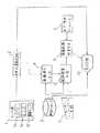
FIG. 38 is a block diagram showing a conventional navigation apparatus described in Japanese Patent Laid-Open No. 8-313286. In the figure, 101 is a display device, 102 is a designation device for designating a map display range, destination designation, etc. 103 is a map memory storing information relating to road networks and road links constituting the road network, 104 Is a required time memory for storing the required travel time of the road link for each date, month, and 105 is a search range limitation that calculates a straight line distance connecting the current location and the destination and limits the route search range based on this straight line distance Device.
[0004]
106 is a route search device for searching for a combination of all road links reaching the destination from the current location based on the road network stored in the
[0005]
The
The
[0006]
The required
[0007]
The
The
[0008]
The current
The enhancement signal generation device 109 generates a signal for highlighting the shortest time route selected by the
The
[0009]
In the navigation device having such a configuration, when the driver designates a destination using the
[0010]
Further, the shortest path is highlighted and displayed on a map displayed on the
Further, when traveling on the guidance route, the actual traveling speed of the route is measured, and the actual required time of the road link is recorded in the required
[0011]
[Problems to be solved by the invention]
In the conventional navigation device, the required time of the road link is obtained by the actual traveling of the route guided as described above, and the shortest route is obtained using this required time, but the vehicle has never traveled. When traveling on a road link, the required time for that road link is not determined by actual driving, so the specified required time is used, and the required time considering the individual driver's preference is reflected. Therefore, the required time cannot be obtained accurately.
[0012]
Therefore, the guidance when setting an unknown point (the first place to go) as the destination uses the required time information without reflecting the individual characteristics, cannot reflect the individual characteristics, and the required time is not sufficient. There is a drawback to become accurate.
Further, when the number of times of travel is small even on a road link that has traveled once, the required time obtained at that time may be different from the required time when the driver normally travels.
[0013]
Furthermore, in the conventional navigation apparatus, the required time difference information is configured to reflect the required time information when an individual driver actually travels the guided route. Therefore, it is only about the individual road link corresponding to the guidance route, and the preference of the traveling speed when traveling in a normal non-guided state is not reflected.
[0014]
In addition, it is preferable from the viewpoint of safe driving to obtain breaks at appropriate intervals during long-distance driving, but only the distance between the destination and the current location is taken into account in the conventional required time calculation. However, there is a drawback that the taking of the break is not taken into consideration, and as a result, the accuracy of the required time deteriorates.
[0015]
The present invention has been made to solve such a problem, and reflects the travel preference of individual drivers by learning the travel characteristics that individual drivers prefer for each road attribute. In addition, for a route to a destination that has not been experienced, it is possible to calculate the required time reflecting the individual characteristics.
[0016]
In addition, by learning the individual's rest characteristics during driving, and using this rest characteristic, the necessary time calculation that takes into account the acquisition of the rest time can be calculated, the accuracy of the required time can be improved, and an appropriate rest The purpose is to contribute to safe driving by proposing to the driver the time, resting position and resting place.
[0017]
[Means for Solving the Problems]
The navigation device according to the present invention provides road segment information for road segments constituting a road network and for each road attribute.I was askedGuidance route search means for calculating the travel information and the required time required for the vehicle to travel on a route composed of road segments from the road segment information and the travel information and searching for a guide route for guiding the vehicle based on the required time And display means for displaying the guidance route searched for by the guidance route search means..
[0018]
AlsoThe travel information is classified for each driver who drives the vehicle.
The travel information is a vehicle speed distribution.
Further, the travel information is a speed distribution with respect to time.
Furthermore, the travel information is a speed distribution with respect to the distance.
The road attribute is at least one of an expressway, a motorway, a main national road, a general national road, a main local road, and a general road.
The travel information is information for each road attribute obtained based on the integrated value of the travel results so far.
[0019]
Moreover, the vehicle situation measuring means for measuring the motion state of the vehicle and the travel characteristic learning means for correcting the travel information of the vehicle based on the motion state measured by the vehicle situation measurement means are provided.
[0020]
In addition, road segment information for road segments constituting the road network,Calculated for each road attributeA guide route search means for searching for a guide route for guiding the vehicle from the break acquisition information related to a driver's break acquisition, road segment information and break acquisition information, and a guide route searched by the guide route search means. Display means for displaying.Also,Break acquisition informationIncluding information related to the travel duration and rest time, the guidance route search means calculates the number of breaks during traveling on the guide route using the travel duration, and searches for the guidance route in consideration of the number of breaks.
[0021]
Further, the guidance route search means searches for the break acquisition point from the road segment information and the break acquisition information, and the display means displays the break acquisition point searched by the guidance route search means.
Further, the guidance route search means searches for a restable facility near the break acquisition point from the road segment information and the break acquisition information, and the display means displays the restable facility searched by the guidance route search means.
[0022]
Further, the guidance route search means searches for a restable facility in the vicinity of the break acquisition point from the road segment information and the break acquisition information, and searches for the guidance route so that the guide route for guiding the vehicle includes the restable facility.
Furthermore, the vehicle situation measuring means for measuring the motion state of the vehicle, and the break acquisition characteristic learning means for correcting the break acquisition information based on the motion state measured by the vehicle state measurement means.
[0023]
The vehicle status measuring means measures the motion state of the vehicle when traveling in a non-guided state where no route search is performed, and the learning means corrects information based on the motion state measured in the non-guided state. To do.
[0024]
DETAILED DESCRIPTION OF THE INVENTION
Hereinafter, an embodiment of the present invention will be described.
FIG. 1 is a block diagram showing an example of a navigation apparatus according to
[0025]
2 is a vehicle position estimation means for estimating the travel position of the vehicle from the vehicle position / motion state measured by the
[0026]
[0027]
[0028]
[0029]
10 reads out the position of the own vehicle estimated by the own vehicle position estimating means 2 and road network data in a predetermined range around the estimated position of the own vehicle from the
[0030]
More specifically, the
[0031]
The own vehicle position estimation means 2 integrates the angle and position changes measured by the yaw rate sensor 1b and the
[0032]
For example, the
[0033]
4 is a diagram showing the data structure of the road link described in FIG. 2, FIG. 4A is an example of the road link, and FIG. 4B is an example of the data structure of the road link shown in FIG. FIG. 4C shows an example of the structure of road attribute data in the data structure.
As shown in FIG. 4A, the road link is normally defined by nodes Ns and Ne with both ends numbered, and a link number Ln is attached to a line segment connecting the nodes Ns and Ne. This road link is recorded in a data structure as shown in FIG. 4B as an example, and the coordinates Xs, Ys, Xe representing the link number Ln, the node numbers Ns, Ne of the start point, the end point, and the positions of the start point, the end point node. , Ye are recorded. The coordinates of the start point and the end point may be numerical values (generally referred to as normalized coordinates) defined in the subdivided sections shown in FIG. 3, or latitude / longitude coordinates or other coordinate systems may be used. Also good.
[0034]
Furthermore, the link length L representing the length of the road link, the node numbers Ns-1, Ns + 1 of other links to which the start point of the road link is connected, and the node numbers of other links to which the end point of the road link is connected Ne-1, Ne + 1, and an attribute list of the road as shown in FIG. 4C are recorded.
[0035]
The road attribute list includes information as shown in FIG. 4C as an example. In the road attribute list of FIG. 4C, as an example, it is recorded that the type of road is a general national road. This road has a regulated speed of 40 km / h, an actual speed of 10 km, and a width of 10 m. The road attribute is recorded such that the number of lanes is 2, the number of lanes is 2, and one-way traffic is restricted.
[0036]
As shown in FIG. 5, the travel
[0037]
When the destination is set by the user interface means 7, the route search means 8 reads the road network around the current location and the destination from the
[0038]
The display means 10 includes, for example, a graphics display element such as a liquid crystal display board, displays the road network recorded in the
[0039]
Next, the operation of the navigation device shown in FIG. 1 will be described. First, the vehicle position estimation means 2 determines the estimated position of the vehicle based on the measurement value measured by the
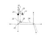
FIG. 6 is a diagram illustrating a vehicle position estimation method. In the figure, 21 is an estimated position determined by autonomous navigation, 22 is an estimated position obtained by a GPS positioning device, 23 is an estimated own vehicle position, and 24 is a movement history of the estimated
[0040]
The
Therefore, the estimated
[0041]
Next, in the road matching means 4, a road network including the position coordinates of the estimated
Then, the
[0042]
On the other hand, when a request for a route search is generated from the driver in the
[0043]
Next, the guidance route search means 9 uses the expression (1) to calculate the required time TSGIs calculated.
[0044]
[Expression 1]
First, the sum of the road distances for each road attribute is obtained for the road links constituting the route from the departure place to the destination set by the route search means 8. Then, the required time for each road attribute is calculated by multiplying the sum of the distances for each road attribute by the travel time per unit distance corresponding to the road attribute as shown in FIG. Finally, by calculating the sum of the required time for each of these road attributes, the required time TSGIs calculated. And this calculated required time TSGThe optimum route is determined based on the above and the optimum route is displayed on the display by the display means 10.
[0046]
A specific example will be described with reference to FIG.
FIG. 7 shows an example of the route set in the route search means 8. In the figure, S is the starting point of the route search, G is the destination and the end point of the route search, and the section display in the drawing is each road. Indicates the attribute. FIG. 8 shows data related to the route shown in FIG.
[0047]
FIG. 9 shows an example of the operation in the route search means. In the figure, 31 to 33 are road network data, [S] is a search starting point, and in many cases is a current position of the vehicle. [G] is a destination designated by the user interface means 7.
[0048]
First, when the destination is set by the user interface means 7 and the start of the search is instructed, as shown in FIG. 9, the route search means 8 performs the
[0049]
Next, when a route as shown in FIG. 9 is selected, the roads included in the searched route are classified by road attribute, and the road attribute-specific distances that are the sum of the distances of the roads belonging to the same road attribute are integrated. Then, the required time for each road attribute is calculated by multiplying the distance for each road attribute by the travel characteristic for each road attribute recorded in the travel
For example, if the road attribute is a general road as shown in FIG.R5, 1(7km) and LR5, 2Therefore, the sum of these is calculated, and the attribute-specific distance of the general road is 20 km.
[0050]
As shown in FIG. 8, the travel characteristic for the attribute of the general road is 0.02564 h / km, so the time required to travel on the section of the general road is 20 × 0.02564 = 0.51 hours. Become.
Thereafter, the same calculation is repeated for each road attribute, and by taking the sum of these, the required time T required to travel through the entire section from the starting point to the destination is obtained.SGIs calculated. (In this case, it will be 3 hours 43 minutes)
Then, optimum routes are obtained based on the time calculated by the guidance route search means 9 and these are displayed on the display by the display means 10.
[0051]
FIG. 10 shows an example of display. In the figure, 51 is a displayed map, 52 is a display of the position of the own vehicle determined by the own vehicle position estimating means 2, and 53 is set by the route searching means 8. The search route is displayed, and 54 is a display of the route to the purpose determined by the guide route search means 9 and the required time.
Here, a liquid crystal display panel is used as the display means 10, but a CRT, plasma display, or other device capable of displaying graphics may be used, and the required time is displayed on a display device centered on characters such as a dot matrix display. You may make it do.
[0052]
In the present embodiment, the road attribute information includes the type of road, the width of the road, and the like. Needless to say, the road attribute information may be classified according to time or weather.
[0053]
In the present embodiment, the characteristic data stored in the travel characteristic database is time data per unit distance, but this is not particularly limited, and speed data may be used instead of the time data.
In this case, the required time T according to the equation (1)SGInstead of calculating the required time T using the following formula:SGIs calculated.
[0054]
[Expression 2]
Further, in the present embodiment, the characteristic data stored in the driving characteristic database is stored for each road attribute, but this is not particularly limited, and is classified for each driver or a combination thereof. May be stored.
[0056]
In this embodiment, since the road link travel characteristics are not stored for each road link but for each road attribute to which the road link belongs, the road link that has never traveled is traveled. Even in the case, even if the required time of the road link is not determined by actual driving, the actual driving data by the driving data of the same attribute is reflected, and the required time considering the individual driver's preference is obtained, Accurate time required can be obtained.
In other words, the personal characteristics are reflected in the guidance when an unknown point (the first time to go) is set as the destination, and an accurate required time can be obtained.
[0057]
In addition, since the driving characteristics are used for each driver's characteristics, even when different drivers use the same vehicle, it is possible to accurately predict the required time reflecting the characteristics of each driver.
[0058]
FIG. 11 is a diagram showing a navigation device according to the second embodiment of the present invention. In the figure, 5 is a road attribute extracting means for extracting a road attribute representing a road attribute recorded along with the road link determined by the road matching means 4, and 6 is a driving characteristic (unit distance) according to the road attribute. This is a travel characteristic database in which a time table for each attribute is stored in order to correct the travel performance and the travel characteristics.
[0059]
[0060]
FIG. 12 shows an example of a highway time table that is a time table when the attribute is a highway. The expressway time table is composed of the accumulated time and the accumulated travel distance, and the accumulated time is the sum of the travel time so far, and the travel distance is the distance traveled within the travel time. Newly added. Although the case where the attribute is a highway is described here, the other road attributes have the same configuration.
[0061]
The present embodiment is the same as the first embodiment except that the travel characteristic learning means 11 corrects the travel characteristic data, and therefore other explanations are omitted.
[0062]
FIG. 13 is a flowchart showing the processing contents of the travel characteristic learning means 11 of the navigation apparatus shown in FIG. This process is started at a predetermined timing.
First, the attribute of the road on the road detected by the road attribute extraction means 5 is input. (S101)
Next, the required time and travel distance required for traveling on the road are input based on the information on the driving situation of the vehicle obtained by the vehicle position estimating means 2. (S102)
[0063]
Then, the attribute of the road attribute input in S101 is determined, and the process to be processed in S104 is switched according to the road attribute during travel. (S103)
Next, for each road attribute determined in S103, the integrated value of the travel time and the travel distance are newly added to update the travel characteristics. (S104)
In the present embodiment, as examples of road attributes to be processed in S104, a case where classification is made into six types of expressway, exclusive road, main national road, general national road, main local road, and general road is shown.
[0064]
Next, an average travel time (travel characteristic) per unit distance is calculated as a travel characteristic value for each road attribute from the relationship between the travel time and the travel distance accumulated in S104. (S105)
Then, the travel characteristic value in the travel
Finally, in preparation for the next learning process, the running integrated time timer is initialized, and this process ends. (S107)
[0065]
These learning processes may be performed in a state where the route search as described in the first embodiment is performed, or only the above learning is performed in a state where the route search is not performed. It may be.
[0066]
In the present embodiment, each road attribute is identified and stored. However, the travel characteristic information stored in the travel
[0067]
In the navigation device according to the second embodiment, the driving characteristics of the driver are corrected by learning according to the attribute of the road on which the driving is performed. Therefore, the driving characteristics are corrected according to the driving of the driver, and more Accurate time estimation that reflects the characteristics is possible.
In addition, since the driving characteristics at the time of non-guided driving in which the route search is not performed are also taken into consideration, it is possible to reflect the preference of the traveling speed in the normal non-guided state in which the route search is not performed. .
[0068]
In the third embodiment of the present invention, the travel characteristics of the travel characteristic database in the navigation device shown in FIG. 11 of the second embodiment are not the travel time per unit distance as shown in FIG. 5, but the speed. is there.
[0069]
FIG. 14 is a diagram showing a time table for each attribute in order to correct the running characteristics (speed) and running characteristics stored in the running characteristics database of this embodiment, and FIG. 14 (a) shows the running characteristics. 14 (b) shows an example of a time table for correcting the running characteristics, and FIG. 14 (c) shows the relationship between the running speed and the accumulated running time.
As shown in FIG. 14A, the travel characteristics of the present embodiment are represented by the speed at which the travel characteristics are classified for each road attribute. The time table shows the relationship between the speed attribute value, the accumulated time, and the time ratio. For example, when the road attribute is a highway, the travel speed is set as shown in FIG. Accordingly, the speed attribute is divided into a plurality of speed attributes, and the accumulated time is obtained for each of the classified speed attributes, and the time ratio occupied by each speed attribute with respect to the entire speed attribute is shown.
[0070]
The accumulated time is obtained by adding a predetermined time each time the speed attribute value and the road attribute value are changed.
In the example shown in FIG. 14, the accumulated traveling time of the highway is most frequently traveled at a traveling speed of 100 to 120 km / h. In other words, the driver prefers this speed band when traveling on the highway. You can see that it is running.
These time tables are composed of the same number of tables as the road attributes.
[0071]
In the present embodiment, the travel characteristic learning means 11 shown in FIG. 11 is adapted to the speed of the travel characteristics, and the traveling road attribute extracted by the road attribute extraction means 5 and the vehicle position estimation means 2 The frequency is learned by associating with the traveling speed of the vehicle obtained in the above, and the traveling characteristic for each road attribute is determined. Then, the travel characteristics for each attribute of the learned road link are stored in the travel
[0072]
Similarly, the guidance route search means 9 uses the expression (2) shown in the first embodiment instead of the expression (1) as in the second embodiment, and the required time TSGIs calculated.
[0073]
FIG. 15 is a flowchart showing the processing contents of the travel characteristic learning means 11. The foundation is activated at a predetermined timing.
First, the attribute of the road on the road detected by the road attribute extraction means 5 is input. (S201)
Next, the traveling speed of the vehicle obtained by the vehicle position estimating means 2 is input. (S202)
Then, based on the traveling speed obtained in S202, a speed attribute to which the speed of the currently traveling vehicle belongs is determined. (S203)
[0074]
Next, in the travel characteristic learning process, the previously detected travel speed attribute is compared with the currently detected speed attribute. As a result of the comparison, if the speed attribute has changed, S206 is executed, and if there is no change in the speed attribute, S205 is executed. (S204)
In S205, with respect to the road attribute of the running road input in S201, a comparison is made between the attribute of the road that was running when the driving characteristic learning process was last activated and the currently detected road attribute. If there is no change in the road attribute, it is determined that the subsequent processing is unnecessary, and the process ends. If it is determined that the road attribute has changed, the process proceeds to S206.
[0075]
In S206, the attribute of the road attribute input in S201 is determined, and the process to be processed in S207 is switched according to the attribute of the running road.
In S207, for each road attribute determined in S206, the integrated value of the time traveled with the speed attribute value determined in S203 is updated.
In the present embodiment, as examples of road attributes to be processed in S207, a case where classification is made into six types of expressway, exclusive road, main national road, general national road, main local road, and general road is shown.
[0076]
In S208, an average traveling speed is calculated as a traveling characteristic value for each road attribute from the relationship between the speed attribute value accumulated in S207 and the accumulated time using a statistical method. For example, when the traveling speed has a traveling speed frequency distribution as shown in FIG. 14B, a simple average of 95 km / h may be used as the traveling characteristic value on the expressway. Alternatively, as the most frequent value, the speed attribute VFive(Attribute
[0077]
Furthermore, in S209, the driving
In S210, the learning of the driving characteristics corresponding to the change in the speed attribute value and the change in the road attribute value is completed in the above processing. Therefore, in preparation for the next learning process, the traveling integrated time timer is initialized. This process ends.
[0078]
FIG. 16 is an explanatory diagram regarding the determination of the speed attribute in S203 and the calculation of the travel time for each speed attribute. In FIG. 16, the horizontal axis represents time, and the vertical axis represents travel speed. Further, as an example of the speed attribute, the travel speed is every 20 km / h, that is, less than 20 km / h, such as 20 km / h or more and less than 40 km / h. A range is set, and a predetermined range including the traveling speed of the vehicle is set as a speed attribute in that state.
The traveling time for each speed attribute is a speed range in which the traveling speed of the vehicle is a predetermined attribute (for example, the speed attribute VFive) Is measured by a timer (not shown) from the time (point a in FIG. 16) to the time (point b in FIG. 16) deviating from the speed range of the attribute.
[0079]
Even within the same speed attribute, when the traveling road attribute changes, the elapsed time measurement ends when the road attribute changes (point c in FIG. 16), and a new road attribute ( For example, R1) Is started. After that, R1When the attribute road continues, the speed attribute (for example, VFour) End elapsed time measurement.
[0080]
A specific example of such an operation will be described with reference to FIG.
FIG. 17 shows data related to the route shown in FIG.
First, the roads included in the searched route of FIG. 7 are classified by road attributes, and the distances by road attributes are integrated. Next, the required time for each road attribute is calculated by dividing the distance for each road attribute by the driving characteristic (speed) for each road attribute recorded in the driving
Thereafter, the same calculation is repeated for each road attribute, and by calculating the sum of these, the required time T required to travel through the entire section from the starting point to the destination is obtained.SGIs calculated.
Others are the same as those described in the second embodiment, and a description thereof will be omitted.
[0081]
In the navigation device of the present embodiment, the vehicle traveling speed, that is, the driving characteristics of the driver is corrected by learning according to the attribute of the road on which the vehicle is traveling in a normal driving state. The driving characteristics are corrected, and it is possible to predict the required time more accurately reflecting the characteristics of the individual.
[0082]
Another embodiment of the present invention will be described. In the third embodiment, the running characteristics are corrected based on the accumulated time as shown in FIG. 14B. In the present embodiment, the accumulated distance is used instead of the accumulated time, and the travel is performed based on these. Modify the characteristics. Since other operations are the same as those in the third embodiment, description thereof is omitted.
FIG. 18 is a view showing a flowchart of processing in the travel characteristic learning means 11 of
In FIG. 18, S301 and S302 are the same as S201 and S202 of FIG.
[0083]
FIG. 19 is an explanatory diagram regarding the determination of the speed attribute in S303 and the calculation of the travel distance for each speed attribute in the travel characteristic learning means 11 according to the fourth embodiment. In FIG. 19, the horizontal axis represents the travel distance, and the vertical axis represents the travel speed, which is the same as FIG. 16 of the third embodiment. The travel distance for each speed attribute is a speed range in which the travel speed of the vehicle is a predetermined attribute (for example, the speed attribute VFive) Is measured from a point (point a in FIG. 19) to a point (point b in FIG. 19) deviating from the speed range of the attribute by a travel distance register (not shown).
[0084]
Even within the same speed attribute, when the traveling road attribute changes, the distance measurement ends when the road attribute changes (point c in FIG. 19), and a new road attribute (for example, , R1) Is started. After that, R1When the attribute road continues, the speed attribute (for example, VFour) End elapsed time measurement.
Hereinafter, only differences in internal processing from S304 to S309 will be described.
[0085]
FIG. 20 shows an example of the highway speed table in S306 in FIG. FIG. 20A shows the relationship between the speed attribute value, the accumulated travel distance, and the distance ratio. The accumulated travel distance is the travel distance obtained in the process of S303 every time the speed attribute value and the road attribute value are changed. It is obtained by integrating ΔL.
In the example shown in FIG. 20, it can be seen that the accumulated travel distance of the highway is most frequently traveled at a travel speed of 100 to 120 km / h, and this speed band is preferably used.
[0086]
The difference between the present embodiment and the first embodiment is that when calculating on a time basis, the elapsed time becomes longer as the vehicle travels at a lower speed, and the characteristic calculation weighted to the lower speed band is performed. On the other hand, in the case of the distance base, the weighting is uniform from low speed to high speed.
[0087]
FIG. 21 is an explanatory diagram of the above differences. For example, assuming that a 100 km section as shown in FIG. 21 (a) travels freely at a distance of 80 km at 90 km / h and travels at a speed of 50 km / h while following the other 20 km. The speed table in this case is shown in FIG.
When the running characteristics are calculated on a time basis for the above conditions, the
[0088]
In S310, similar to S210 of the third embodiment, learning of the driving characteristics corresponding to the change of the speed attribute value and the change of the road attribute value is completed in the processes from S301 to S309, so that the next learning process is prepared. The mileage register is initialized and the process is terminated.
[0089]
In the navigation device of the present embodiment, in learning of the driving characteristics of each driver in a normal driving state, learning of the driving characteristics is calculated by adding the distance traveled by the driving speed attribute, and this is calculated as the road attribute. Since it is stored as a separate travel characteristic database, in addition to the third embodiment, it is possible to accurately predict the required time reflecting the individual characteristics.
[0090]
FIG. 22 is a diagram showing the configuration of the navigation device according to the fifth embodiment of the present invention. In the figure,
[0091]
In addition to the operation in the navigation device of FIG. 11, 9 calculates the number of breaks to be acquired when traveling on the route searched for from the characteristics of the break acquisition recorded in the travel
[0092]
10 is a display means for displaying the route to the destination, required time, recommended break time, etc. in addition to the display of the map and the search route, and 12 is the information on the vehicle using the information of the vehicle position estimating means 2 and the road matching means 4 A break determination means 13 for determining a break situation from the running state is a break characteristic learning means 13 for inputting a break situation obtained by the break determination means 12 and learning a driver's break characteristic. Others are the same as the operation of the navigation apparatus described in FIG.
[0093]
Next, the operation of the present embodiment will be described. Since the present embodiment is the same as the third embodiment except that the rest characteristic is used, other description is omitted.
Based on the result determined in the break determination means 12, the rest characteristic learning means 13 learns the break characteristics of the running characteristic database, and the guidance route search means performs a route search using these characteristic values.
[0094]
First, in the break determination means 12, whether or not the vehicle is present on the current road link from the positional relationship between the vehicle movement state measured by the own vehicle position estimation means 2 and the road determined by the road collation means 4. It is estimated whether or not the driver is in a resting state.
[0095]
Next, the break characteristic learning means 13 learns the characteristics of each driver's break acquisition from the break state determined by the break determination means 12 and the break time information. Here, as the characteristics of the break acquisition, for example, a travel duration time during which the vehicle continuously travels, a break acquisition time during which a break is performed, and the like can be cited.
FIG. 23 is an explanatory diagram of the outline of the break acquisition characteristic. In the figure, the horizontal axis represents time, the vertical axis represents vehicle speed, and the curve in the figure represents the traveling speed pattern of the vehicle.
First, the break acquisition characteristic is the travel duration T from the start of travel to the start of the break.runAnd the break acquisition time T from the start of the break to the restart of the runrestMeasure. Then, a break acquisition characteristic is determined by statistically processing these measured values and recorded in the running
[0096]
Then, the guidance route search means 9 calculates the required time as follows.
FIG. 24 is a diagram showing an example of required time calculation in the guide
[0097]
FIG. 24B shows the calculation result in the required time calculation in the present embodiment, and the search route and other conditions for the required time calculation are the same as those in the required time calculation example in the third embodiment. is there.
If the required time is calculated from the road distance of all sections and the travel characteristics for each road attribute as described in the third embodiment, 3 hours and 43 minutes are required.
[0098]
In addition, since the average travel duration recorded in the driving characteristic database of the driver is 1 hour and 20 minutes, this section is set to 3 as shown in FIG. 24B so as to match the driving characteristic of the driver. It is desirable to travel in two sections.
And in order to divide and run as described above, it takes 15 minutes per break, so in the case of this driver, the time required to travel this section is 3 hours and 43 minutes. It will take 4 hours and 13 minutes plus 30 minutes of break time.
[0099]
FIG. 25 is a diagram illustrating an example of processing of the
The contents of the process will be described below.
First, the movement state of the vehicle represented by the moving speed of the vehicle is inputted from the vehicle position estimation means 2. (S401)
Next, the state of collation with the road, that is, the positional relationship between the current position of the host vehicle and the road link is input from the road collating means 4. (S402)
[0100]
And about the road collation state input by S402, it determines about whether the vehicle exists on a present road link. If it is determined that the road is on the road, the following processing is omitted and the present processing is terminated. If there is a vehicle outside the road, that is, away from the road link and in some facility or parking lot, S404 is executed because there is a possibility of a break. (S403)
In S404, it is determined whether or not the vehicle is running from the vehicle motion state input in S401. If it is determined that the vehicle is traveling, S408 is executed to determine whether the vehicle is traveling on a road not recorded in the map database, traveling outside the road, or whether the vehicle is restarting after a break. . If it is determined that the vehicle is stopped, S405 is executed.
[0101]
In S405, a break determination flag is inspected in order to determine whether or not it is the first break candidate state after this processing is activated. If the break determination flag has been set, it is determined that the break candidate is already in the state, and the following process is omitted, and this process is terminated. If the break determination flag is not set, the first break candidate state is assumed and S406 is executed.
In S406, since it has been determined that the user is in the break candidate state by the processing so far, in order to start the measurement of the break time, the timer is started, and in S407, the fact that the break candidate is in the initial state is stored. Set the break judgment flag.
[0102]
In S408, the break determination flag is inspected. If the flag is not set, it is determined that the vehicle is traveling on the road outside the data or on the road outside the data, and this processing is terminated. If the flag has been set, it is determined that the vehicle has started running after a break, and S409 is executed.
In S409, the break time is measured from the timer started in S406, and the timer is initialized. In S410, the break determination flag is canceled in preparation for the next break determination.
[0103]
The navigation device of the present embodiment is configured to learn the time required for continuous travel and the time required for a break, and to store this as a break acquisition characteristic in the travel characteristic database, so that a search route from the departure point to the destination The required time required for driving is calculated by reflecting the normal driving characteristics of each driver, and the required time is calculated in consideration of the break time that should be included in the required time. Therefore, it is possible to calculate the required time with a margin taking into account the acquisition of the break time, to accurately predict the required time reflecting the characteristics of each individual, and to propose an appropriate break time to the driver It is possible to contribute to safety improvement.
[0104]
Further, in the present embodiment, as in the third embodiment, the driving characteristics are learned using time as a characteristic reference, but in the same manner as in the fourth embodiment, the distance is used as a characteristic reference to determine the driving characteristics. You may study. In this case, there is an advantage that the driving characteristics of the driver can be more accurately defined, and an advantage that it is possible to roughly determine at which point a break should be taken in comparison with all routes.
[0105]
The break determination means 12 in the fifth embodiment is configured to determine the break time only by the determination of the stop and restart in the off-road driving, but in this embodiment, in addition to this, the break time is determined. Let them judge whether it is a break according to the length. Others are the same as those of the fifth embodiment, and thus description thereof is omitted.
[0106]
FIG. 26 is a flowchart showing the processing of the break determination means 12 in the present embodiment.
In FIG. 26, the operation from S501 to S510 is the same as S401 to S410 in FIG.
In S511, the predetermined value of the break time defined in advance is compared with the break time measured in S509 to determine suitability. For example, if the measured break time is shorter than a predetermined value and cannot be determined to be a break, the break time data measured this time is discarded in S512, and S510 is executed. If the measured break time is longer than the predetermined value and the break condition is met, the break determination flag is released in preparation for the next measurement in S510 and the present process is terminated.
[0107]
In the navigation device configured as described above, it is possible to measure the rest time without being influenced by a slight detour or a slight stop at a vending machine, etc., improving the learning accuracy of running characteristics It becomes possible to do.
[0108]
Further, in the user interface means, the home position and the destination position are set, and the resting position is determined by using the set home position or destination position information and the vehicle position information measured by the own vehicle position estimating means. If it is configured such that parking at home and parking at the destination can be clearly distinguished, learning accuracy is further improved.
[0109]
In addition, when a very short distance is frequently used such as daily shopping, it is predicted that the average travel duration or the average travel duration in the travel characteristic database is smaller than the original characteristic value. Therefore, in order to avoid such a problem, the break time may be learned only when the route search is performed.
[0110]
FIG. 27 is a diagram showing a navigation device according to the seventh embodiment of the present invention. In the figure,
14 is a recommended break point setting unit that calculates a recommended break point from a search route between predetermined places calculated by the
[0111]
Next, the operation of the present embodiment will be described. In the present embodiment, the rest recommended point is determined in the recommended break
[0112]
The recommended break point setting means 14 inputs the road attribute and the distance between the road attributes from the route search means 8 for the sequentially set routes from the departure point to the destination. Further, the travel characteristic for the road attribute is input from the travel
[0113]
In FIG. 28A, the first line is a section number indicating a section having a specific attribute from the departure place, the second line is a road attribute of each section, the third line is a section distance of the section, and these data Is obtained from the searched route information in the route searching means 8.
The fourth line is a driving characteristic (specifically, a driving speed) for each road attribute inputted from the driving
The fifth line is a section travel time required for traveling in each section, and can be obtained by dividing the section distance obtained by the route search means 8 by the travel characteristic value recorded in the travel
[0114]
Next, a method for calculating a recommended break point in the recommended break point setting means 16 will be described.
In FIG. 28 (b), the section distance, section travel time, and searched route are the same as in FIG. 28 (a). For the searched route, the break acquisition characteristic (continuous running time T recorded in the running characteristic database 6).run) To determine the recommended break point from the route. That is, for the first break point, TrunA point where the vehicle exists when the time has elapsed is calculated using the section distance and the travel characteristic value for each road attribute, and this point is set as the first recommended break point. Next, starting from the first recommended break point, TrunWhen the time has elapsed, a point where the vehicle exists is calculated, and this point is set as a second recommended break point. Similarly, the recommended break point is obtained, and this is repeated until all routes are included, thereby setting the recommended break point.
[0115]
FIG. 29 shows the recommended break points set by the recommended break point setting means 14 in comparison with the road network used for the calculation. In the figure, R indicates the recommended break point.
FIG. 30 is an example of the display of the recommended break point on the display means 10, in which 52 indicates the current position of the vehicle, 53 indicates the search route to the calculated destination, and 55 indicates the recommended break point setting means. This is a recommended break point.
[0116]
In the navigation device of the present embodiment, instead of reflecting the acquisition of the break only in the required time, the break recommended point is calculated and displayed on the map in combination with the searched route and the driving characteristics, so the appropriate break position Can recognize the timing of taking a break more visually to the driver, and contribute to driving safety.
[0117]
Further, in the present embodiment, as a form of the break characteristic learning means 13 and the running
[0118]
FIG. 31 is a conceptual diagram of a method for calculating a recommended break point when distance is used as a reference for characteristics. In FIG. 31, the section distance, the section travel time, and the searched route are the same as those in FIG. About the searched route, the break acquisition characteristic (continuous travel distance L) recorded in the travel characteristic database 6run) To determine the recommended break point from the route. That is, for the first break point, L from the departure pointrunA point separated by a distance is set as a first recommended break point. Next, starting from the first recommended break point, further LrunA point separated by a distance is set as the second recommended break point. Similarly, the recommended break point is obtained, and this is repeated until all routes are included, thereby setting the recommended break point.
[0119]
In the case described with reference to FIG. 28 (b), the continuous travel time TrunThe distance was calculated using the travel characteristic value and the point calculation was performed taking into account the magnitude relationship with the section distance of the searched route. LrunThe point can be calculated by dividing the section with.
In this way, by using the distance as a reference of the characteristic, the calculation of the recommended break point is not continuous running time, but continuous running distance LrunThis makes it easy to calculate points and has the advantage of reducing the computer load for calculating recommended break points.
[0120]
FIG. 32 is a diagram showing a configuration of the entire navigation device according to the eighth embodiment of the present invention. In the figure,
[0121]
FIG. 33 is a diagram showing a display of rest-releasable facilities in the vicinity of the recommended break point R55 displayed by the
FIG. 34 is a conceptual diagram of a search for a facility capable of resting near the point R shown in FIG. In FIG. 34, point R is a recommended break point set by the recommended break point setting means 14, and the △ mark and ◇ mark around it are position information and facility names of the peripheral facilities stored in the map database. .
The surrounding facility search means 15 determines whether or not the distance between the recommended break point R and the surrounding facilities is equal to or less than a predetermined value, and if it is equal to or less than the predetermined value, it is a restable facility near the recommended break point. The position information and the facility type are output to the display means 10.
[0122]
In the example shown in FIG. 34, the restaurants A, D, and the cafe B exist below a predetermined value (within a predetermined radius). Therefore, as shown in FIG. .
As shown in FIG. 33, the display means 10 receives the output of the surrounding facility search means 15 and displays the
[0123]
In the navigation device of the present embodiment, facilities that can be rested in the vicinity of the recommended break point are searched from the map database and displayed on the map, so the resting place where the rest can actually be taken is visually determined. It is possible to convey to the driver, and it is possible to take a break without hesitation even in unfamiliar land, and it is possible to contribute to the safety of traveling.
[0124]
FIG. 35 is a diagram showing a configuration of the entire navigation device according to the ninth embodiment of the present invention. In the figure,
15 retrieves resting facilities in the vicinity of the recommended break points from the information of various facilities recorded in the
Others are the same as those in the eighth embodiment, and thus the description thereof is omitted.
[0125]
The operation of this embodiment will be described. In the present embodiment, when the guidance route is obtained, the guidance route is obtained taking into consideration the recommended break point. Except for the guide route search method, it is the same as that of the eighth embodiment, and the other description is omitted.
[0126]
First, in the route search means 8, information related to the setting of the break point selected by the user interface means 7 is input, and point information about the resting facility searched by the peripheral search means 15 is input, and a predetermined point When performing a search in between, the optimal route is searched using the selected resting facility as a transit point.
[0127]
FIG. 36 is an example of a display of recommended break point selection on the display means 10 in the ninth embodiment. Similar to the operation of the eighth embodiment, the peripheral search means 15 searches for restable facilities near the recommended break point and creates a list of restable facilities for each recommended break point.
The
[0128]
The route search means 8 determines whether or not the waypoint setting is instructed by the user interface means 7. If the restable facility is not set as the waypoint, the route search means 8 performs a normal search, and the restable facility becomes the waypoint. If set, position information is input from the surrounding facility search means 15 for all the resting facilities that have been set.
Furthermore, the route search means 8 performs a route search between predetermined points so that the positions of these peripheral facilities are included in the route.
The searched optimum route is displayed together with the map by the display means 10 in the same manner as in the above embodiment, and guides the driver.
[0129]
FIG. 37 is an example of the display in the ninth embodiment. When one point (◇ Tea B) of the break recommended facility candidates in the eighth embodiment is selected, the
In the description of the present embodiment, only the case of a general road has been described with reference to the drawings. However, in an automobile-only road such as an expressway, a service area and a parking area on the route should be given priority as a resting facility. It may be configured.
[0130]
In the navigation device of the present embodiment, instead of reflecting the acquisition of the break only in the required time, the break recommended point is calculated in combination with the searched route and the driving characteristics, and the break that exists in the vicinity of the recommended break point is also calculated. It is configured to search for possible facilities from the map database and search the route so that it is included in the search route connecting the predetermined points, so when actually taking a break and actually running, the required time closer to the actual time required Time can be calculated, breaks can be obtained without hesitation even in unfamiliar land, and it is guided to the break point accurately without looking at the map, improving convenience and driving safety It becomes possible to contribute to.
[0131]
Further, in the fifth to ninth embodiments, as shown in FIG. 24, the average travel duration and the average break time that are not for each road attribute are obtained, but the travel characteristics described in the first to fourth embodiments Similarly, the average travel duration and the average break time may be obtained for each road attribute.
[0132]
【The invention's effect】
The navigation device according to the present invention calculates the required time required for the vehicle to travel on a route composed of road segments for each road segment information and road attribute.I was askedIt is calculated from the travel information, and the guidance route for guiding the vehicle is searched based on this required time. Therefore, when traveling on a road link that has never traveled or when the number of travels is small, the road link The required time is obtained from information obtained by actual driving on a road having the same attribute, and the required time in consideration of the individual driver's preference is obtained.
[0133]
Since the travel information is classified for each driver who drives the vehicle, even when different drivers use the same vehicle, it is possible to predict the required time reflecting the characteristics of each driver.
[0134]
Since the travel information is a vehicle speed distribution, it can be classified into a plurality of speed attributes for one road link, and the travel characteristics of each driver can be obtained using various methods.
[0136]
Since the vehicle situation measuring means for measuring the motion state of the vehicle and the travel characteristic learning means for correcting the travel information of the vehicle based on the motion state measured by the vehicle situation measurement means, the vehicle travels. Thus, the travel information can be corrected, the required time can be calculated more reflecting the travel preference of each individual driver, and the accuracy of the required time prediction can be improved.
[0137]
Since the guide route for guiding the vehicle is searched from the road segment and the break acquisition information, the accuracy of the required time can be improved, and it is possible to contribute to the safety of traveling by considering an appropriate break.
[0139]
The route search means searches for the break acquisition point from the road segment and the break acquisition information, and the display means displays the vacation acquisition point searched for by the route search means, so that the driver can recognize the break acquisition point. This makes it possible to visually tell the driver when to take a break and contribute to driving safety.
[0140]
In the route search means, the resting facility in the vicinity of the break acquisition point is searched from the road segment information and the break acquisition information, and the resting facility searched in the route searching means is displayed in the display means. The location where the break can be acquired can be recognized, and the location where the break can be acquired can be understood without hesitation even in unguided land, thereby contributing to the safety of driving.
[0141]
In the route search means, search for a restable facility near the break acquisition point from the road segment and the break acquisition information, and search for the guide route so as to include the restable facility in the guide route for guiding the vehicle from the road segment. Knowing the exact time required including the actual break, it is possible to get a break without hesitation even in unfamiliar land, and it is guided to the break point accurately without looking at the map, so convenience and driving It is possible to contribute to the improvement of safety.
[0142]
Vehicle situation measuring means for measuring the movement state of the vehicle, and break acquisition characteristic learning means for correcting break acquisition information stored in the break acquisition characteristic database based on the movement state measured by the vehicle situation measurement means Therefore, when the vehicle travels, it is possible to correct the break acquisition characteristics, and it is possible to calculate the required time reflecting the driving preference of each individual driver, and improve the accuracy of the required time prediction. It becomes possible.
[0143]
The vehicle status measuring means measures the motion state of the vehicle when traveling in a non-guided state without performing route search, and the learning means corrects information based on the motion state measured in the non-guided state It is also possible to reflect the preference of the traveling speed when traveling in an unguided state.
[Brief description of the drawings]
FIG. 1 is a diagram showing a navigation device according to a first embodiment of the present invention.
FIG. 2 is an explanatory diagram of a road network expression.
FIG. 3 is an explanatory diagram of a map management method.
FIG. 4 is an explanatory diagram of a description example of a road network.
FIG. 5 is a diagram showing running characteristics of
FIG. 6 is an explanatory diagram of the operation of the vehicle position estimating means and the road collating means.
FIG. 7 is an explanatory diagram of a required time calculation example according to the first embodiment of the present invention.
FIG. 8 is an explanatory diagram of a required time calculation example according to the first embodiment of the present invention.
FIG. 9 is an explanatory diagram of the operation of the route search means of FIG.
FIG. 10 is a diagram showing an example of display according to the first embodiment of the present invention.
FIG. 11 is a diagram showing a navigation device according to a second embodiment of the present invention.
FIG. 12 is a diagram showing a time table according to the second embodiment of the present invention.
FIG. 13 is a flowchart of the second embodiment of the present invention.
FIG. 14 is an explanatory diagram of an example of travel characteristics according to the third embodiment of the present invention.
FIG. 15 is a flowchart of
FIG. 16 is an explanatory diagram of the operation of the travel characteristic learning unit according to the third embodiment.
FIG. 17 is a diagram showing data for the route shown in FIG. 7;
FIG. 18 is a flowchart of the fourth embodiment of the present invention.
FIG. 19 is an explanatory diagram of the operation of the running characteristic learning means of the fourth embodiment.
FIG. 20 is a diagram showing a time table according to the fourth embodiment of the present invention.
FIG. 21 is an explanatory diagram for calculating travel characteristics according to the fourth embodiment of the present invention.
FIG. 22 is a diagram showing a navigation device according to a fifth embodiment of the present invention.
FIG. 23 is an explanatory diagram of the operation of the break determination means of FIG.
FIG. 24 is an explanatory diagram for calculating required time according to the fifth embodiment of the present invention.
FIG. 25 is a flowchart of
FIG. 26 is a flowchart of
FIG. 27 is a diagram showing a navigation device according to a seventh embodiment of the present invention.
FIG. 28 is an explanatory diagram for calculating a recommended break point according to the seventh embodiment of the present invention.
FIG. 29 is a conceptual diagram of a break recommendation point according to the seventh embodiment of the present invention.
FIG. 30 is a diagram showing a display example of recommended break points according to the seventh embodiment of the present invention.
FIG. 31 is an explanatory diagram of calculation of recommended break points according to the seventh embodiment of the present invention.
FIG. 32 shows a navigation device according to an eighth embodiment of the present invention.
FIG. 33 is a conceptual diagram of a breakable facility display according to
34 is an explanatory diagram of the operation of the peripheral facility search means of FIG. 32. FIG.
FIG. 35 is a diagram showing a navigation device according to a ninth embodiment of the present invention.
36 is a diagram showing an example of display contents of the display means of FIG. 35. FIG.
FIG. 37 is a diagram showing an example of display according to the ninth embodiment of the present invention.
FIG. 38 is a diagram showing a conventional navigation device.
[Explanation of symbols]
DESCRIPTION OF
1b
2 Vehicle location estimation means 3 Map database
4 Road verification means 5 Road attribute extraction means
6 Driving
8 Route search means 9 Guide route search means
10 Display means 11 Travel characteristic learning means
12 Break determination means 13 Break characteristic learning means
14 Recommended break point setting means 15 Peripheral facility search means
21
23 Estimated
25 Road link 26 Current location of the vehicle
27 Branch point of
31-33 Road network data
51
53 Display of searched route 54 Display of road and required time
55
103
105 Search
107
109 Enhancement
Claims (13)
Translated fromJapanesePriority Applications (1)
| Application Number | Priority Date | Filing Date | Title |
|---|---|---|---|
| JP15990097AJP3719310B2 (en) | 1997-06-17 | 1997-06-17 | Navigation device |
Applications Claiming Priority (1)
| Application Number | Priority Date | Filing Date | Title |
|---|---|---|---|
| JP15990097AJP3719310B2 (en) | 1997-06-17 | 1997-06-17 | Navigation device |
Publications (2)
| Publication Number | Publication Date |
|---|---|
| JPH116741A JPH116741A (en) | 1999-01-12 |
| JP3719310B2true JP3719310B2 (en) | 2005-11-24 |
Family
ID=15703633
Family Applications (1)
| Application Number | Title | Priority Date | Filing Date |
|---|---|---|---|
| JP15990097AExpired - Fee RelatedJP3719310B2 (en) | 1997-06-17 | 1997-06-17 | Navigation device |
Country Status (1)
| Country | Link |
|---|---|
| JP (1) | JP3719310B2 (en) |
Families Citing this family (22)
| Publication number | Priority date | Publication date | Assignee | Title |
|---|---|---|---|---|
| JP2001174273A (en)* | 1999-12-16 | 2001-06-29 | Denso Corp | Map display apparatus |
| JP3657835B2 (en)* | 1999-12-27 | 2005-06-08 | 日本電信電話株式会社 | Information providing method and information providing system |
| JP4368025B2 (en)* | 2000-02-16 | 2009-11-18 | 富士通テン株式会社 | Break point setting method and navigation device |
| DE10028457A1 (en)* | 2000-06-08 | 2001-12-13 | Bosch Gmbh Robert | User adaptive process for a road vehicle driver information system allows driver input to modify decision making process |
| JP2002122437A (en)* | 2000-10-18 | 2002-04-26 | Matsushita Electric Ind Co Ltd | Route guidance device |
| JP4601033B2 (en)* | 2000-12-27 | 2010-12-22 | 株式会社エクォス・リサーチ | Light distribution control device |
| JP2002312885A (en)* | 2001-04-11 | 2002-10-25 | Toyota Motor Corp | Required time estimation system and required time estimation method |
| US6629034B1 (en)* | 2001-06-06 | 2003-09-30 | Navigation Technologies Corp. | Driving profile method and system |
| JP3857604B2 (en)* | 2002-03-26 | 2006-12-13 | 株式会社東芝 | Mobile information terminal |
| WO2004034725A1 (en) | 2002-10-10 | 2004-04-22 | Matsushita Electric Industrial Co., Ltd. | Information acquisition method, information providing method, and information acquisition device |
| JP4341378B2 (en)* | 2003-11-10 | 2009-10-07 | 株式会社デンソー | Navigation device |
| JP2008538809A (en)* | 2005-04-25 | 2008-11-06 | コタレス・リミテッド | Apparatus and method for supplying data to external applications |
| JP2008039698A (en)* | 2006-08-09 | 2008-02-21 | Univ Nagoya | Sequential map matching system, sequential map matching method, and sequential map matching program |
| JP4853332B2 (en)* | 2007-02-28 | 2012-01-11 | トヨタ自動車株式会社 | Information provision device |
| WO2009037752A1 (en)* | 2007-09-19 | 2009-03-26 | Pioneer Corporation | Navigation apparatus, computational speed enhancing method, and program |
| EP2203714B1 (en)* | 2007-10-26 | 2017-05-10 | TomTom Traffic B.V. | A method of creating map data |
| JP5024134B2 (en) | 2008-03-14 | 2012-09-12 | アイシン・エィ・ダブリュ株式会社 | Travel information creation device, travel information creation method and program |
| JP2010266323A (en)* | 2009-05-14 | 2010-11-25 | Mitsubishi Electric Corp | Map display device |
| JP2012159413A (en)* | 2011-02-01 | 2012-08-23 | Canvas Mapple Co Ltd | Navigation device and navigation program |
| JP6303795B2 (en)* | 2014-05-15 | 2018-04-04 | 日産自動車株式会社 | Route search system and route search method |
| JP6957093B2 (en)* | 2017-08-03 | 2021-11-02 | アルパイン株式会社 | Attention device and attention method |
| CN113324555B (en)* | 2021-05-31 | 2024-05-03 | 阿波罗智联(北京)科技有限公司 | Method and device for generating vehicle navigation path and electronic equipment |
Family Cites Families (5)
| Publication number | Priority date | Publication date | Assignee | Title |
|---|---|---|---|---|
| JP2784972B2 (en)* | 1992-02-12 | 1998-08-13 | 本田技研工業株式会社 | Route search device |
| JPH07159194A (en)* | 1993-12-10 | 1995-06-23 | Casio Comput Co Ltd | Navigation device |
| JP3204037B2 (en)* | 1995-05-02 | 2001-09-04 | 日産自動車株式会社 | Car navigation system |
| JPH097087A (en)* | 1995-06-16 | 1997-01-10 | Aqueous Res:Kk | Guidance device |
| JP3593749B2 (en)* | 1995-06-26 | 2004-11-24 | 株式会社エクォス・リサーチ | In-vehicle route search device |
- 1997
- 1997-06-17JPJP15990097Apatent/JP3719310B2/ennot_activeExpired - Fee Related
Also Published As
| Publication number | Publication date |
|---|---|
| JPH116741A (en) | 1999-01-12 |
Similar Documents
| Publication | Publication Date | Title |
|---|---|---|
| JP3719310B2 (en) | Navigation device | |
| CN102037324B (en) | Method and system for point-of-interest search along a route | |
| JP4511426B2 (en) | Vehicle navigation device | |
| JP5051010B2 (en) | Parking lot guidance device, parking lot guidance method and program | |
| JP3395737B2 (en) | Navigation device | |
| JP3406144B2 (en) | Route guidance device for vehicles | |
| US6941222B2 (en) | Navigation system, server system for a navigation system, and computer-readable information recorded medium in which destination prediction program is recorded | |
| US8706408B2 (en) | Navigation system and route search method | |
| JP2001174280A (en) | Route selection method and system, and recording medium | |
| JP5692628B2 (en) | Navigation device and navigation program | |
| JP3941095B2 (en) | Navigation device | |
| JP3800285B2 (en) | Navigation device and recording medium | |
| JP4076905B2 (en) | Navigation device | |
| JP4061781B2 (en) | Navigation system | |
| JPH05118866A (en) | Vehicle route guidance device | |
| JP2009257965A (en) | Navigation device | |
| JP3491867B2 (en) | Route selection method and system | |
| JP4646499B2 (en) | Route search method for navigation device | |
| JP2005156350A (en) | Destination prediction apparatus, navigation apparatus, and destination prediction method | |
| JP3941605B2 (en) | Car navigation system | |
| JP3661754B2 (en) | Navigation device and recording medium | |
| JPH10281785A (en) | Navigation device for vehicle and medium storing computer program for navigation processing | |
| JP2008241349A (en) | Method of estimating traveling time, navigation device, and program | |
| JP2002243486A (en) | Navigation device | |
| JPH0989579A (en) | Navigation device equipped with a traveling locus display function |
Legal Events
| Date | Code | Title | Description |
|---|---|---|---|
| RD01 | Notification of change of attorney | Free format text:JAPANESE INTERMEDIATE CODE: A7421 Effective date:20040625 | |
| A977 | Report on retrieval | Free format text:JAPANESE INTERMEDIATE CODE: A971007 Effective date:20041125 | |
| A131 | Notification of reasons for refusal | Free format text:JAPANESE INTERMEDIATE CODE: A131 Effective date:20041130 | |
| A521 | Written amendment | Free format text:JAPANESE INTERMEDIATE CODE: A523 Effective date:20050127 | |
| TRDD | Decision of grant or rejection written | ||
| A01 | Written decision to grant a patent or to grant a registration (utility model) | Free format text:JAPANESE INTERMEDIATE CODE: A01 Effective date:20050817 | |
| A61 | First payment of annual fees (during grant procedure) | Free format text:JAPANESE INTERMEDIATE CODE: A61 Effective date:20050830 | |
| FPAY | Renewal fee payment (event date is renewal date of database) | Free format text:PAYMENT UNTIL: 20080916 Year of fee payment:3 | |
| FPAY | Renewal fee payment (event date is renewal date of database) | Free format text:PAYMENT UNTIL: 20090916 Year of fee payment:4 | |
| FPAY | Renewal fee payment (event date is renewal date of database) | Free format text:PAYMENT UNTIL: 20090916 Year of fee payment:4 | |
| FPAY | Renewal fee payment (event date is renewal date of database) | Free format text:PAYMENT UNTIL: 20100916 Year of fee payment:5 | |
| FPAY | Renewal fee payment (event date is renewal date of database) | Free format text:PAYMENT UNTIL: 20110916 Year of fee payment:6 | |
| FPAY | Renewal fee payment (event date is renewal date of database) | Free format text:PAYMENT UNTIL: 20110916 Year of fee payment:6 | |
| FPAY | Renewal fee payment (event date is renewal date of database) | Free format text:PAYMENT UNTIL: 20120916 Year of fee payment:7 | |
| FPAY | Renewal fee payment (event date is renewal date of database) | Free format text:PAYMENT UNTIL: 20130916 Year of fee payment:8 | |
| LAPS | Cancellation because of no payment of annual fees |