JP3718550B2 - Dispensing device for fluid monitor sensor - Google Patents
Dispensing device for fluid monitor sensorDownload PDFInfo
- Publication number
- JP3718550B2 JP3718550B2JP00108696AJP108696AJP3718550B2JP 3718550 B2JP3718550 B2JP 3718550B2JP 00108696 AJP00108696 AJP 00108696AJP 108696 AJP108696 AJP 108696AJP 3718550 B2JP3718550 B2JP 3718550B2
- Authority
- JP
- Japan
- Prior art keywords
- sensor
- pack
- dispensing device
- holding means
- disposed
- Prior art date
- Legal status (The legal status is an assumption and is not a legal conclusion. Google has not performed a legal analysis and makes no representation as to the accuracy of the status listed.)
- Expired - Lifetime
Links
- 239000012530fluidSubstances0.000titleclaimsabstractdescription38
- 238000012360testing methodMethods0.000claimsabstractdescription105
- 239000011888foilSubstances0.000claimsabstractdescription41
- 239000002274desiccantSubstances0.000claimsabstractdescription24
- 238000004891communicationMethods0.000claimsabstractdescription5
- 238000012545processingMethods0.000claimsdescription16
- 230000002093peripheral effectEffects0.000claimsdescription5
- 238000007789sealingMethods0.000claimsdescription5
- 238000000034methodMethods0.000claimsdescription3
- 230000000149penetrating effectEffects0.000claimsdescription2
- 230000000284resting effectEffects0.000claims1
- 239000008280bloodSubstances0.000abstractdescription37
- 210000004369bloodAnatomy0.000abstractdescription37
- WQZGKKKJIJFFOK-GASJEMHNSA-NGlucoseNatural productsOC[C@H]1OC(O)[C@H](O)[C@@H](O)[C@@H]1OWQZGKKKJIJFFOK-GASJEMHNSA-N0.000abstractdescription26
- 239000008103glucoseSubstances0.000abstractdescription26
- 230000007246mechanismEffects0.000abstractdescription9
- 239000000463materialSubstances0.000description13
- 239000004973liquid crystal related substanceSubstances0.000description12
- 239000003153chemical reaction reagentSubstances0.000description11
- 239000000523sampleSubstances0.000description10
- 238000010998test methodMethods0.000description6
- 229910001220stainless steelInorganic materials0.000description4
- 239000010935stainless steelSubstances0.000description4
- 230000004913activationEffects0.000description3
- 238000004159blood analysisMethods0.000description3
- 239000000126substanceSubstances0.000description3
- 230000009471actionEffects0.000description2
- 239000000853adhesiveSubstances0.000description2
- 230000001070adhesive effectEffects0.000description2
- 230000002411adverseEffects0.000description2
- 239000011324beadSubstances0.000description2
- NOESYZHRGYRDHS-UHFFFAOYSA-NinsulinChemical compoundN1C(=O)C(NC(=O)C(CCC(N)=O)NC(=O)C(CCC(O)=O)NC(=O)C(C(C)C)NC(=O)C(NC(=O)CN)C(C)CC)CSSCC(C(NC(CO)C(=O)NC(CC(C)C)C(=O)NC(CC=2C=CC(O)=CC=2)C(=O)NC(CCC(N)=O)C(=O)NC(CC(C)C)C(=O)NC(CCC(O)=O)C(=O)NC(CC(N)=O)C(=O)NC(CC=2C=CC(O)=CC=2)C(=O)NC(CSSCC(NC(=O)C(C(C)C)NC(=O)C(CC(C)C)NC(=O)C(CC=2C=CC(O)=CC=2)NC(=O)C(CC(C)C)NC(=O)C(C)NC(=O)C(CCC(O)=O)NC(=O)C(C(C)C)NC(=O)C(CC(C)C)NC(=O)C(CC=2NC=NC=2)NC(=O)C(CO)NC(=O)CNC2=O)C(=O)NCC(=O)NC(CCC(O)=O)C(=O)NC(CCCNC(N)=N)C(=O)NCC(=O)NC(CC=3C=CC=CC=3)C(=O)NC(CC=3C=CC=CC=3)C(=O)NC(CC=3C=CC(O)=CC=3)C(=O)NC(C(C)O)C(=O)N3C(CCC3)C(=O)NC(CCCCN)C(=O)NC(C)C(O)=O)C(=O)NC(CC(N)=O)C(O)=O)=O)NC(=O)C(C(C)CC)NC(=O)C(CO)NC(=O)C(C(C)O)NC(=O)C1CSSCC2NC(=O)C(CC(C)C)NC(=O)C(NC(=O)C(CCC(N)=O)NC(=O)C(CC(N)=O)NC(=O)C(NC(=O)C(N)CC=1C=CC=CC=1)C(C)C)CC1=CN=CN1NOESYZHRGYRDHS-UHFFFAOYSA-N0.000description2
- 238000004519manufacturing processMethods0.000description2
- 239000002184metalSubstances0.000description2
- 238000012806monitoring deviceMethods0.000description2
- 102000004877InsulinHuman genes0.000description1
- 108090001061InsulinProteins0.000description1
- 238000004458analytical methodMethods0.000description1
- 238000006243chemical reactionMethods0.000description1
- 230000000295complement effectEffects0.000description1
- 239000004020conductorSubstances0.000description1
- 230000008878couplingEffects0.000description1
- 238000010168coupling processMethods0.000description1
- 238000005859coupling reactionMethods0.000description1
- 230000000881depressing effectEffects0.000description1
- 230000000994depressogenic effectEffects0.000description1
- 206010012601diabetes mellitusDiseases0.000description1
- 238000007599dischargingMethods0.000description1
- 229940079593drugDrugs0.000description1
- 239000003814drugSubstances0.000description1
- 230000009977dual effectEffects0.000description1
- 238000009459flexible packagingMethods0.000description1
- -1for exampleSubstances0.000description1
- 229940125396insulinDrugs0.000description1
- 238000012423maintenanceMethods0.000description1
- 230000014759maintenance of locationEffects0.000description1
- 230000013011matingEffects0.000description1
- 238000012544monitoring processMethods0.000description1
- 238000004806packaging method and processMethods0.000description1
- 239000008188pelletSubstances0.000description1
- 239000000843powderSubstances0.000description1
- 230000008569processEffects0.000description1
- 229920002379silicone rubberPolymers0.000description1
- 239000004945silicone rubberSubstances0.000description1
- 208000024891symptomDiseases0.000description1
Images


Classifications
- G—PHYSICS
- G01—MEASURING; TESTING
- G01N—INVESTIGATING OR ANALYSING MATERIALS BY DETERMINING THEIR CHEMICAL OR PHYSICAL PROPERTIES
- G01N1/00—Sampling; Preparing specimens for investigation
- G—PHYSICS
- G01—MEASURING; TESTING
- G01N—INVESTIGATING OR ANALYSING MATERIALS BY DETERMINING THEIR CHEMICAL OR PHYSICAL PROPERTIES
- G01N33/00—Investigating or analysing materials by specific methods not covered by groups G01N1/00 - G01N31/00
- G01N33/48—Biological material, e.g. blood, urine; Haemocytometers
- G01N33/483—Physical analysis of biological material
- G01N33/487—Physical analysis of biological material of liquid biological material
- G01N33/4875—Details of handling test elements, e.g. dispensing or storage, not specific to a particular test method
- B—PERFORMING OPERATIONS; TRANSPORTING
- B01—PHYSICAL OR CHEMICAL PROCESSES OR APPARATUS IN GENERAL
- B01L—CHEMICAL OR PHYSICAL LABORATORY APPARATUS FOR GENERAL USE
- B01L99/00—Subject matter not provided for in other groups of this subclass
- G—PHYSICS
- G01—MEASURING; TESTING
- G01N—INVESTIGATING OR ANALYSING MATERIALS BY DETERMINING THEIR CHEMICAL OR PHYSICAL PROPERTIES
- G01N35/00—Automatic analysis not limited to methods or materials provided for in any single one of groups G01N1/00 - G01N33/00; Handling materials therefor
- G01N35/00029—Automatic analysis not limited to methods or materials provided for in any single one of groups G01N1/00 - G01N33/00; Handling materials therefor provided with flat sample substrates, e.g. slides
- G01N2035/00089—Magazines
- Y—GENERAL TAGGING OF NEW TECHNOLOGICAL DEVELOPMENTS; GENERAL TAGGING OF CROSS-SECTIONAL TECHNOLOGIES SPANNING OVER SEVERAL SECTIONS OF THE IPC; TECHNICAL SUBJECTS COVERED BY FORMER USPC CROSS-REFERENCE ART COLLECTIONS [XRACs] AND DIGESTS
- Y10—TECHNICAL SUBJECTS COVERED BY FORMER USPC
- Y10T—TECHNICAL SUBJECTS COVERED BY FORMER US CLASSIFICATION
- Y10T436/00—Chemistry: analytical and immunological testing
- Y10T436/11—Automated chemical analysis
- Y10T436/110833—Utilizing a moving indicator strip or tape
- Y—GENERAL TAGGING OF NEW TECHNOLOGICAL DEVELOPMENTS; GENERAL TAGGING OF CROSS-SECTIONAL TECHNOLOGIES SPANNING OVER SEVERAL SECTIONS OF THE IPC; TECHNICAL SUBJECTS COVERED BY FORMER USPC CROSS-REFERENCE ART COLLECTIONS [XRACs] AND DIGESTS
- Y10—TECHNICAL SUBJECTS COVERED BY FORMER USPC
- Y10T—TECHNICAL SUBJECTS COVERED BY FORMER US CLASSIFICATION
- Y10T436/00—Chemistry: analytical and immunological testing
- Y10T436/11—Automated chemical analysis
- Y10T436/112499—Automated chemical analysis with sample on test slide
Landscapes
- Health & Medical Sciences (AREA)
- Engineering & Computer Science (AREA)
- Life Sciences & Earth Sciences (AREA)
- Biomedical Technology (AREA)
- Physics & Mathematics (AREA)
- Chemical & Material Sciences (AREA)
- Analytical Chemistry (AREA)
- Pathology (AREA)
- Immunology (AREA)
- General Physics & Mathematics (AREA)
- General Health & Medical Sciences (AREA)
- Biochemistry (AREA)
- Biophysics (AREA)
- Medicinal Chemistry (AREA)
- Food Science & Technology (AREA)
- Urology & Nephrology (AREA)
- Molecular Biology (AREA)
- Hematology (AREA)
- Optics & Photonics (AREA)
- Clinical Laboratory Science (AREA)
- Chemical Kinetics & Catalysis (AREA)
- Automatic Analysis And Handling Materials Therefor (AREA)
- Investigating Or Analysing Biological Materials (AREA)
- Sampling And Sample Adjustment (AREA)
- Investigating Or Analysing Materials By Optical Means (AREA)
Abstract
Description
Translated fromJapanese【0001】
【発明の属する技術分野】
本発明は一般に、流体モニタシステムに関し、より詳細には、血中グルコースまたはその中に含まれる他の被検体を分析するのに使用される多数のセンサを取り扱うための新規で改良された装置に関する。
【0002】
【従来の技術】
種々の症状の糖尿病を病む人達は、日常的に自らの血液を試験して血中グルコースの濃度を測定しなければならない。そのような試験の結果を使用して、どのようなインスリンまたは他の薬剤を投与する必要があるのかを決めることができる。あるタイプの血中グルコース試験システムでは、センサを使用して血液試料を試験する。
【0003】
そのようなセンサは、前端、すなわち試験端および後端、すなわち接触端をもつほぼ平坦な長方形であることができる。センサは、血中グルコースと反応する生感知性物質または試薬物質を含有する。センサの試験端は、試験される流体、例えば、人の指を何かで穿刺したのちその指の上に溜る血液の中に配置されるようなっている。流体は、毛管作用により、センサ中を試験端から試薬物質まで延びる毛管路の中に引き込まれて、試験するのに十分な量の流体がセンサに引き込まれるようになる。そして、流体はセンサ中の試薬物質と化学反応を起こし、その結果、試験される血液中の血中グルコース濃度を示す電気信号が、センサの後端、すなわち接触端の近くに位置する接触区域に供給される。
【0004】
センサの接点で発生した電気信号をモニタ機器に結合するためには、センサの端部を試験される流体の中に配置する前に、センサをセンサホルダに挿入しなければならない。ホルダは、センサをホルダに挿入したときにセンサ上の接点に結合される対応する嵌合い式の接点区域を有している。その結果、ホルダは、センサと、試験結果を蓄積および/または解析するモニタ機器との間のインタフェースとして働く。
【0005】
使用する前に、センサは、センサ中の試薬物質の完全性維持を保証するために、適当な湿度レベルに維持されなければならない。センサは、適切な湿度レベルに維持することができるよう、引きはがし式のパッケージに1個ずつ包装することができる。例えば、ブリスタタイプの包装方法を使用してもよい。これに関連して、パッケージは、パッケージ中に適当な湿度または乾燥レベルを維持するための乾燥剤を含むことができる。血中グルコースを試験するために個々のセンサを使用するためには、シールを引きはがすことによってパッケージを開封しなければならない。あるいはまた、パッケージによっては、使用者がパッケージの一側に対して力を加えて、その結果、パッケージの箔の反対側でセンサの破裂または破れを生じさせる必要がある。察知しうるように、これらのパッケージの開封が難しいこともある。そのうえ、一度パッケージを開封したならば、使用者は、センサをセンサホルダの中に配置し、血液試料を試験するために使用するときに、そのセンサが破損していたり汚染されたりしていないことを確認しなければならない。
【0006】
【発明が解決しようとする課題】
したがって、本発明の目的は、血中グルコースを試験するのに使用される多数のセンサの新規で改良されたセンサパックおよびそのようなセンサパックに含まれるセンサを取り扱うための分与装置を提供することにある。特に、本発明の目的は、複数の流体センサを含むセンサパックを受け入れて、センサ分与装置上の送りアクチュエータを試験位置に動かしたときに個々のセンサを選択的に試験位置に配することができるようにし、送りアクチュエータがその待機位置に戻される間にセンサパックを自動的に割り出して、センサの別の一つを試験位置に配することができるようになっている新規で改良された流体センサ分与装置取扱い装置を提供し、駆動装置上に旋回自在に取り付けられた切断装置を有し、この切断装置が、センサパックからセンサを放出して放出されたセンサを試験位置に配し、駆動装置が待機位置に戻されるときにはセンサパックから離れるようになっている新規で改良された流体センサ分与装置を提供し、個々のセンサのための複数のキャビティをもち、キャビティそれぞれが、センサキャビティからのセンサの放出を容易にするための支持面を有するものであるセンサパックを有する新規で改良された流体センサ分与装置を提供し、個々のセンサをセンサ分与装置中のデータ処理機器に結合するための接触装置を提供して、個々のセンサからのデータを表示することができるようにしている新規で改良された流体センサ分与装置を提供し、分与装置のヒンジ付き部に配置された較正機構であって、曲がりくねった通路に配置されたいくらか可撓性のコネクタによって分与装置の別のヒンジ付き部に設けられたデータ処理機器に相互接続された較正機構を有する新規で改良された流体センサ分与装置を提供し、センサパックに設けられた切欠きと嵌り合ってセンサパックを割出し装置に対して適切に配置し、センサパックが割出し装置とともに回転することを保証する保持装置を有する新規で改良された流体センサ分与装置を提供することにある。
【0007】
【課題を解決するための手段】
本発明の前記の目的および他多くの目的にしたがって、本発明は、複数の血中グルコースセンサを含むセンサパックを受け入れるようになっているセンサ分与装置に具現化される。各センサは、センサ中の試薬物質と反応させるために流体を引き込む際に通すところの前側試験端および反対側の後側接触端をもつほぼ平坦な長方形である。センサパックは、センサ保持キャビティまたは凹みが形成されているところのほぼ円形のベース部を含む。各センサ保持キャビティは、センサの一つを受け入れるようになっており、乾燥剤が配置されている対応する乾燥剤キャビティと流体連通している。乾燥剤は、センサ中の試薬物質がセンサが使用される前に悪影響を受けることのないよう、対応するセンサキャビティが適当な湿度または乾燥レベルに維持されることを保証するためにキャビティに配置されている。箔が、ベース部に対し、そのベース部の外周縁全体にわたって、また、センサ保持キャビティと乾燥剤キャビティとの各組の外周全体にわたってヒートシールされてセンサ保持キャビティおよび乾燥剤キャビティをシールして、個々のセンサが乾燥状態に維持され、互いに隔てられるようにしている。その結果、一つのセンサキャビティの開封が他のセンサキャビティのいずれの乾燥状態にも影響することはない。
【0008】
各センサキャビティは支持壁を有し、センサをセンサキャビティに配置したとき、この支持壁の上に個々のセンサが載る。支持壁は、ベース部の周縁に隣接するところからベース部の中心に向かって半径方向に延びている。センサキャビティからのセンサの放出を支援するため、支持壁は、ベース部を封止する箔に向かって、ベース部の周縁に向かう方向に傾斜した傾斜部を含む。センサパックはさらに、センサパックの外周縁に沿って形成された、それぞれがセンサキャビティ一つに対応する一連の切欠きを含む。
【0009】
センサ装置は、上側ケースおよび下側ケースを有する外側ハウジングを含み、上側ケースおよび下側ケースは互いに対してクラムシェル式に旋回することができ、センサパックを、ハウジング中、その中に配置された割出し盤の上に配置することができるようにする。センサパックをハウジングに装填した状態で、ハウジングの上側ケースに配置されたスライドアクチュエータ上のスライドラッチが、スライドアクチュエータの動きが装置を表示もしくはデータ処理モードまたは試験モードのいずれに入れるのかを制御する。
【0010】
スライドラッチを横方向に動かし、スライドアクチュエータをその待機位置から離すと、装置はその表示モードに入る。表示モードにあるとき、装置を使用する人は、上側ケースの表示ユニット上に表示されたデータを見ることもできるし、データを装置に入力することもできる。
【0011】
スライドラッチがその通常位置にあり、スライドアクチュエータがその試験位置に向けて押されると、装置はその試験モードに入る。ハウジングの上側ケースの中でスライドアクチュエータと係合する送り機構もまた、その待機位置から試験位置に向けて動かされる。この送り機構は駆動装置を含み、この駆動装置の上にはナイフ刃が旋回自在に取り付けられ、また、この駆動装置から割出し盤駆動アームが延びている。スライドアクチュエータがその起動位置に向けて動かされると、ナイフ刃を上に備えた駆動装置が送り機構の試験位置に向かって動き、割出し盤駆動アームが、割出し盤中を半径方向に延びるまっすぐな溝の中を移動して、送り機構がその試験位置に向かって動くときには割出し盤が回転しないようになる。ナイフ刃は、駆動装置がその待機位置から離れ始めるときリフトばねの下でカムトラックの第一の部分に載るカム従動子を有している。トラックの第一の部分はセンサパックに向かって傾斜して、ナイフ刃が、割出し盤上に配置されたセンサパックのセンサキャビティの一つに向かって動くようになっている。ナイフ刃は、ナイフ刃と一直線に並んだセンサキャビティを覆う箔を穿通し、キャビティ中に配置されたセンサと係合する。スライドアクチュエータおよび駆動装置がアクチュエータの作動位置に向けて押されると、ナイフ刃は、センサキャビティを覆う箔をさらに切断し、センサをセンサキャビティの外に押し出す、または放出して、センサの偏倚した前縁がセンサキャビティを覆う外側箔をつき破るようになる。センサは、センサキャビティの外に押し出されるとき、センサキャビティの傾斜した支持壁に沿って移動して、センサが、ナイフ刃によって前に進められるとき、箔をセンサパックのベース部に固定するヒートシールの中に押し込まれずに済むようになる。センサを箔の中に動かすのに要する力は、センサの前部の尖った偏倚形状によって最小限になって、センサが、単に箔を伸ばすのではなく、その中に出口穴を切り開けるようになる。
【0012】
スライドアクチュエータの、その試験位置に向かうスライドの継続の結果として、センサがセンサキャビティから完全に放出される。センサハウジングの試験端の近くに配置されたガイドが、センサキャビティから出たセンサを試験位置に案内する。これが起こるとき、駆動装置の前部のカム面が、センサの試験端がハウジングの試験端から突出した状態で、センサをその試験位置に維持するセンサアクチュエータと係合する。センサアクチュエータは、センサ上の対応する接点と嵌り合う接点を含む。センサ分与装置は、マイクロプロセッサまたはセンサアクチュエータに同様に電気結合された他のデータ処理回路を含むことができ、センサを試験される血液に挿入したときにセンサから得られるデータを処理することができるようになっている。そして、処理されたデータは、装置の上側ケースのスクリーンに表示したり、他の分析機器における使用に備えて記憶したりすることができる。
【0013】
血液分析試験が完了したならば、スライドアクチュエータをその待機位置に向けて反対方向に動かす。スライドアクチュエータがその試験位置から離れるとき、駆動装置はセンサアクチュエータから離れて、センサアクチュエータ上の接点がセンサ上の対応する接点から離れ、センサを分与装置から取り外すことができるようになる。駆動装置の引込みが継続する結果、ナイフアセンブリ上のカム従動子がリフトばねに載り、ナイフ刃がセンサパックから離れて、割出し盤がセンサパックを前進させるようになる。これに関して、駆動装置から延びる割出し盤駆動アームが、割出し盤中の半径方向に延びる溝に相互接続された曲線状に延びる溝に沿って移動し始めて、結果的に割出し盤の回転をもたらす。また、割出し盤の回転は結果的にセンサパックの回転をもたらして、センサキャビティの次の一つがナイフ刃と一直線に並ぶ位置に配されて、センサキャビティ中のセンサを、次に実施すべき血中グルコース試験に使用することができるようになる。
【0014】
分与装置は、センサパックを割出し盤に取り付けたときにセンサパック上のラベルに接触するプローブをもつ較正回路を含む。この較正回路が、センサパックおよびセンサパック中のセンサを用いて実施される試験に関するデータをデータプロセッサに提供する。
【0015】
【発明の実施の形態】
本発明は、上記および他の目的および利点とともに、図面に表す本発明の実施態様の以下の詳細な説明から明確に理解することができる。
【0016】
まず、図面を具体的に参照すると、符号30によって示す本発明を具現化する血中グルコースセンサ分与装置が示されている。このセンサ分与装置30は、上側ケース34および下側ケース36を有する外側ハウジング32を含む。上側ケース34は下側ケース36に対して二枚貝の貝殻のように旋回することができ、センサパック38(図5〜9)をハウジング32中の割出し盤(図10のインデキシング・ディスク)40上に配置することができるようになっている。センサパック38をそのようにハウジング32に装填した状態で、ハウジング32の上側ケース34上のスライドアクチュエータ42を、上側ケース34の後端46に隣接する待機位置(図1〜3)から、上側ケース34の前端、すなわち試験端48に隣接する作動位置、すなわち試験位置(図4)に向けて手で押すと、このスライドアクチュエータ42を動かして、上側ケース34の内側に固着された、符号44によって示す送り機構(図10)に係合させることができる。スライドアクチュエータ42はまた、センサ分与装置30をデータ処理モードまたは表示モードに入れるためにも動かすことができる。
【0017】
送り機構44は駆動装置50を含み、この駆動装置にはナイフ刃アセンブリ52が旋回自在に取り付けられ、この駆動装置から割出し盤駆動アーム54が延び、この駆動装置には偏倚ばね56が取り付けられている。スライドアクチュエータ32をその作動位置に向けて動かすと、ナイフ刃アセンブリ52を上に備えた駆動装置50が試験端48に向かって動き、割出し盤駆動アーム54の遠位端にあるボタン58が、割出し盤40中の複数の半径方向に延びる溝60A〜Jの一つの中で移動して、駆動装置50がその試験位置に向けて動かされる間、割出し盤40が回転しないようになっている。ナイフ刃アセンブリ52が試験端48に向けて動かされると、ナイフ刃アセンブリ52上のナイフ刃62が、箔64(図5)のうち、複数のセンサキャビティ66A〜Jの一つ、例えばキャビティ66Fを覆う部分を、ナイフ刃62と一直線に並ぶセンサパック38のベース部68で穿通する。キャビティ66Aに配置されたセンサ70がナイフ刃と係合するし、その結果、ナイフ刃62が、キャビティ66Fを覆う箔64をさらに切断し、センサ70をセンサキャビティ66Fから外に押し出す、または放出する。
【0018】
センサ70がセンサキャビティ66Fから完全に放出されたのち、駆動装置50がセンサアクチュエータ74の接触端72と係合し、この接触端がセンサ70に押し付けられ、それにより、センサ70を、試験端48から突出する試験位置に維持する(図4)。センサアクチュエータ74は、センサ70を、上側ケース34に配置されたプリント回路板76上の電子回路に結合する。プリント回路板76上の回路は、血中グルコース試験手順の間に生成されたデータを処理、記憶および/または表示するためのマイクロプロセッサなどを含んでもよい。
【0019】
血液分析試験が完了したならば、スライドアクチュエータ42を、上側ケース34の後端46に隣接するその待機位置に向けて反対方向に手で引き込み、センサ70をセンサアクチュエータ74の接触端72から解放して、センサ70をハウジング32から取り出すことができるようにする。駆動装置50も同様に後端46に向けて戻されて、割出し盤駆動アーム54上のボタン58が、半径方向に延びる溝60Aに相互接続された複数の曲線状に延びる溝80A〜Jの一つ、例えば溝80Aに沿って移動し始め、その結果、割出し盤40の回転が起こる。割出し盤40の回転はまた、結果的にセンサパック38の回転をもたらして、センサキャビティ66A〜Jの次の一つがナイフ刃62と一直線に並ぶ位置に配されて、次のセンサキャビティ66E中のセンサ70を次の血中グルコース試験手順に使用することができるようになる。
【0020】
図1〜4および図9〜11に見てとれるように、センサ分与ハウジング32の上側ケース34および下側ケース36は、下側ケース36の後部84の中を外向きに延びて上側ケース34の後部88のピボットホール86に入るピボットピン82を中心に互いに対して旋回するようになっている相補的でほぼ丸形の中空の容器である。上側ケース34および下側ケース36は、内向きに延びてラッチ90のピボットホール90に入るピン94によって下側ケース36の前部、すなわち試験部92に旋回自在に取り付けられたラッチ90により、図1〜4に示すそれらの閉じた形状に維持される。ラッチを上向きに旋回させると、ラッチは、上側ケース34の前端部、すなわち試験端部100の凹み98にはさまり、それにより、上側ケース34と下側ケース36とをそれらの閉じた形状に固定する。
【0021】
上側ケース34は、その上側外壁104において、前部100から後部88に隣接するところまで延びる凹み102を有している。スライドアクチュエータ42がこの凹み102の中に取り付けられて、側方に延びる肩106が凹み102の縁に沿って対向する溝108の中をスライドする。スライドラッチ110が、スライドクリップ112により、スライドアクチュエータ上の位置に保持されている。このスライドクリップは、スライドアクチュエータ42の下面に配置され、凹み102に設けられた開口116の中を延びるクリップ114を含み、スライドアクチュエータ42にはさまり、モードアクチュエータ118を有している。スライドラッチ110は、センサ分与装置30を使用する人がスライドラッチ110およびスライドアクチュエータ42を動かし易くする面を提供する複数の盛り上がったこぶ120を含む。
【0022】
スライドラッチ110の移動が装置を二つの作動モードのいずれかに入れる。第一の、すなわち試験モードでは、スライドラッチ110は、図1、2および4に示す位置に配される。第二の、すなわちデータ処理モードでは、スライドラッチ110は、スライドアクチュエータ42に対して横方向にスライドしている。
【0023】
スライドラッチ110がその試験モード位置にあるとき、スライドラッチ110の下側部分にあるC字形のキャッチ122がスライドアクチュエータ42の開口126の縦方向に延びる部分124に配置される(図9を参照)。以下に説明するように、このキャッチ122は凹み102のスロット128の中に突出して、スライドアクチュエータ42を試験端48に向けて動かすときに、駆動装置50から上向きに延びるポスト130と係合する。他方、スライドラッチ110の下側部にあるC字形のキャッチ122は、開口126の横方向に延びる部分132に配置されて、センサ分与装置30のデータ処理モードにおいてスライドアクチュエータ42を試験端48に向けて動かすとき、キャッチ122がスロット133中を動くようになっている。その結果、装置30がそのデータ処理モードにあるときには、キャッチ122はポスト130と係合しない。
【0024】
上側ケース34はその後部88に長方形の開口134を含む。この開口134にはレンズ136が配置されて、スライドアクチュエータ42を上側ケース34の後端46から離したときに、レンズ136の下方に取り付けられた液晶表示ユニット138をレンズ136越しに見ることができるようになっている。この液晶表示ユニット138は、コネクタ140および142を介してプリント回路板76上の回路に結合されている。装置30がそのデータ処理または表示モードにあるときに液晶表示ユニット138上に出る表示は、後端46に配置された作動ボタン143および対応するパッド144ならびに作動ボタン146および対応するパッド147によって制御される。例えば、ボタン143および146を押下すると、液晶表示ユニット138上に表示される試験情報を見たり、入力したりすることができる。
【0025】
上側ケース34はまた、1対のバッテリ150および152が配置されているバッテリホルダ148を含む。このホルダ148は、上側ケース34の、前部100に隣接する側部149に挿入される。そのように挿入されると、バッテリ150および152は、装置30内の、プリント配線板76上の回路および液晶表示ユニット138を含む電子部品のための電力を供給する。
【0026】
装置をその試験モードまたはそのデータ処理もしくは表示モードに入れるために、2個の作動スイッチ154および156が設けられている。スイッチ154および156はいずれも、凹み102中のそれぞれの開口158および160の中を延びている。スライドラッチ110がその試験位置にあるとき、スライドアクチュエータ42を試験端48に向けて動かすと、スライドクリップ112上のモードアクチュエータ118が両方のスイッチ154および156を作動させ、それにより、装置30をその試験モードに入れる。他方、モードアクチュエータ118は、スライドラッチ110が横方向に動かされてその表示位置に達し、スライドアクチュエータ42が前端48に向けて動かされたとき、スイッチ154のみを作動させる。その結果、装置30は、モードアクチュエータ110によってスイッチ154だけが動かされ、スイッチ156は動かされないとき、その表示モードに入り、スイッチ154および156の両方が動かされるとき、その試験モードに入る。
【0027】
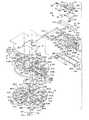
ブロックガイド162と、プリント回路板76と、センサアクチュエータ74と、ハウジングガイド164と、ナイフばね166と、ナイフアセンブリ52と、駆動装置50とが、これらの部品の中を延び、上側ケース34に入る固定具168〜171によっていっしょに保持され、上側ケース34に固着される(図10を参照)。加えて、割出し盤40が、割出し盤40の中央の穴178の中を延び、ハウジングガイド164の開口180に掛り止まる1対のラッチアーム174および176を有するリテーナ172によってハウジングガイド164上に回転自在に保持されることにより、上側ケース34に対して固着される。
【0028】
先に示したように、スライドアクチュエータ42が装置30を使用する人によって試験端48に向けて進められるとき、スライドラッチ110上のC字形クリップ122が駆動装置ポスト130と係合すると、駆動装置50は上側ケース34の前端、すなわち試験端48に向けて進められる。駆動装置50は、駆動装置50の前縁186に隣接する拡大した凹み184まで縦方向に延びる中央の凹み182を有するプラスチック成形部品である。1対のカム突起188および190が前縁186から延び、試験手順の間に駆動装置50が前に押し進められるときに、センサアクチュエータ74の接触端に係合するようになっている。駆動装置50は、ナイフ刃アセンブリ52上の対向するピボットピン194および196が配置される凹み182から外向きに延びる対向する凹み192を含む。その結果、ナイフ刃アセンブリ52は駆動装置50上に旋回自在に取り付けられて、ナイフ刃アセンブリ52の対向する側から突出する対向するカム従動子198および200が駆動装置50の前縁186の近くにある拡大した凹み184の中に配置されるようになっている。以下に論じるように、カム従動子198および200は、ブロックガイド162に形成されたカム面202および204に沿って移動するようになっている。
【0029】
駆動装置50はまた、駆動装置50から後向きに延びる割出し盤駆動アーム54を含む。この割出し盤駆動アーム54は、ばねタイプ材料、例えばステンレススチール製であって、アーム54の遠位端に取り付けられたボタン58が、駆動装置50が前端48に向けて進められるときには、割出し盤40の半径方向に延びる溝60A〜Jの一つの中を移動し、駆動装置50が上側ケース34の後端46に向けて戻されるときには、割出し盤40の曲線状に延びる溝80A〜Jの一つの中を移動することができるようになっている。
【0030】
カム従動子198および200を凹み184の中に延ばすために、偏倚ばね56が、駆動装置50に対し、ナイフ刃アセンブリ52の上方で配置され、これがナイフ刃アセンブリ52に対して下向きの力を加える。カム従動子198および200はまた、凹み184が凹み206と整合したときに、ナイフばね166中の縦方向に延びるスロット208の拡大した凹み206の中にも延びる。ナイフばね166は、駆動装置50の下方に配置され、スロット208の各側にばね脚210および212を含む。ばね脚210は坂路部214を有し、ばね脚212は坂路部216を有している。駆動装置50が後端46に向けて戻されるとき、カム従動子198および200がそれぞれこれらの坂路部214および216に載り上げ、それにより、ナイフアセンブリ52が駆動装置50とともに後端46に向けて戻されるとき、刃ナイフアセンブリ52、特にナイフ刃62を割出し盤40上に配置されたセンサパック38から持ち上げる。
【0031】
駆動装置50は、ブロックガイド162に固着されたハウジングガイド164上に取り付けられて、センサアクチュエータ74およびプリント回路板76がそれらの間にはさまれるようになっている。ハウジングガイド164は、レンズ136および液晶表示ユニット138が配置されている後部フレーム部218を含む。ガイドレール部220が後部フレーム部218からハウジングガイド164の前端219に向かって延びている。ガイドレール部220は、前方に延びる2本のレール222および224を有し、これらのレール222および224の外端には固着穴226〜229が位置している。固着具168〜171がそれぞれ穴226〜229の中に延びている。レール222は上側カムトラック230を有し、レール224は上側カムトラック232を有している。カムトラック230は、カム従動子198が、カムトラック230および202によって形成されるカムトラックに入る際に通過する開口234を有し、同様に、カムトラック232は、カム従動子200が、カムトラック232および204によって形成されるカムトラックに入る際に通過する開口236を有している。センサアクチュエータガイド238がハウジングガイド164の前端219に配置され、これが、センサ70が試験手順に使用されているときにセンサアクチュエータ74の接触端72の、センサ70に対する位置を適切に維持するのに役立つ。
【0032】
センサアクチュエータ74は、センサ70をその試験位置に維持し、センサ70をプリント回路板76上の回路に結合するために使用される。センサ接触端72は、1対の接触アーム242および244によって回路接触部240に接続されている。接触アーム242および244は、プラスチックをステンレス鋼上に成形したものでできているため、いくらか可撓性である。接触アーム242のステンレス鋼部は、センサ接点端72から延びるセンサ接点246と、回路接触部240に設けられたリング接点248との間に結合され、逆にこのリング接点248はプリント回路板76上の回路に結合されている。同様に、接触アーム244のステンレス鋼部は、センサ接点端72から延びるセンサ接点250と、回路接触部240に設けられたリング接点252との間に結合され、逆にこのリング接点252はプリント回路板76上の回路に結合されている。センサ70の1個が試験位置に配されると(例えば図4に示すように)、駆動装置50の前縁186から延びるカム突起部188および190がセンサアクチュエータ74の接触端72に当接して接触端72を下向きに押しやり、センサアクチュエータ74に設けられたポスト254がセンサ70に押し当てられて、センサ70をその試験位置に維持するようになる。ポスト254はまた、接触端72の下面をセンサ70から適切な距離に配置して、センサ接点246および250が、センサ接点246および250がセンサ70との間で所望の接触をなすことを保証するのに適切な量だけ撓められるようになっている。
【0033】
先に示したように、センサアクチュエータ74は、血中グルコース試験に使用されているセンサ70をプリント回路板76上の回路に結合する。プリント回路板がブロックガイド162に取り付けられると、リング接点248および252が、プリント回路板76上の対応する開口256および258の中に突出する接点に結合される。プリント回路板76上の回路はまた、コネクタ140および142を介して液晶表示ユニット138にも結合される。さらに、プリント回路板76上の回路は、装置30において使用されているセンサパック38に関する情報を決定するのに使用される、下側ケース36に位置する較正回路260(図11)にも結合されなければならない。そのように較正回路260をプリント回路板76上の回路に結合するために、弾性コネクタ261が、ブロックガイド162の後端263に位置する通路262の中に配置される。
【0034】
弾性コネクタ261はシリコーンゴムの層でできており、これらの層は、上縁261Aから下縁261Bまで延び、交互の層が導電物質を中に分散して有して、上縁261Aの接点を下縁261Bの接点に接続している。上側ケース34と下側ケース36とを閉じると、コネクタ261が縁261Aと縁261Bとの間の方向に圧縮されて、上縁261Aに沿う接点が上側ケース34の中でプリント回路板76上の回路と係合し、下縁261Bに沿う接点が下側ケース36の中で較正回路260と係合するようになる。弾性コネクタ261がそのように圧縮された状態で、低電圧信号をコネクタ261を介してプリント回路板76と較正回路260との間に容易に結合することができる。コネクタ261を縁261Aと縁261Bとの間の方向に圧縮しなければならず、同時に、装置30を開けたときに通路262中に配置されたままになければならないことを考慮して、通路262は、内向きに延びて通路262に入る丸状の縁264A〜Eにより、曲がりくねった形状である。図10に見られるように、縁264Bおよび264Dは、通路262の片側から内向きに、通路262の反対側から内側に延びる縁264A、264Cおよび264Eの間を延びる。通路262の曲がりくねった形状がいくらか可撓性のコネクタ261を通路262に容易に挿入し、その中に維持することを可能にし、さらに、上側ケース34と下側ケース36とを閉じたときにコネクタ261を圧縮することを可能にする。
【0035】
ブロックガイド162はカムトラック202および204を含む。カムトラック202および204はカムトラック230および232に対して並んで位置し、それらの間に、駆動装置50がその試験位置に向けて動かされるときカム従動子198および200が通過するところのトラックを形成する。カムトラック202は、カムトラック230の下向きに延びるカム面230Aに隣接する下向きに延びるカム面202Aを有し、カムトラック204は、カムトラック232の下向きに延びるカム面232Aに隣接する下向きに延びるカム面204Aを有し、カムトラック202は、カムトラック230の上向きに延びるカム面230Bに隣接する上向きに延びるカム面202Bを有し、カムトラック204は、カムトラック232の上向きに延びるカム面232Bに隣接する上向きに延びるカム面204Bを有している。以下に論じるように、カム従動子198がカム面202Aおよび202Bに載り、カム従動子200がカム面204Aおよび204Bに載って、センサ70がキャビティから試験位置に放出されるときに、ナイフ刃62がブロックガイド162中のカムトラック202と204との間のスロット268を通って突出し、箔64のうち、センサキャビティ66A〜Jの、スロット268と一直線に並んだ一つを覆う部分を切断するようになる。センサ70がそのようにキャビティから放出されるとき、センサは、ブロックガイド162の前部に設けられた、ラッチ90のセンサスロット271と一直線に並んだセンサガイド270のセンサスロット269を通って突出する。
【0036】
もう一つのスロット272がブロックガイド162の後縁263に向かって後方に延びている。このスロット272は、試験手順の間に駆動装置50が前方に動かされ、次いで後方に動かされるときに、割出し盤駆動アーム54およびアーム54の遠位端に設けられたボタン58がスロット272を通って割出し盤40上の溝60A〜Jおよび80A〜Jの中を動くことができるように設計されている。
【0037】
ブロックガイド162は、ブロックガイド162を上側ケース34の適切な位置に取り付けるために固着具168〜171がそれぞれ中を延びる取付け穴274〜277を含む。ブロックガイド162が上側ケース34にそのように配置されると、ブロックガイド162中の可撓性バッテリ接点278がバッテリホルダ148の開口280を介してバッテリホルダ148中のバッテリ150および152に結合される。このバッテリ接点278は、プリント回路板76上の回路と接触し、それに電力を供給する、ブロックガイド162から延びる可撓性電気接点282に結合されている。ブロックガイド162はまた、センサアクチュエータ74の接触アーム242および244のための支持面283および284を提供する。
【0038】
先に示したように、割出し盤40はリテーナ172によってブロックガイド162に取り付けられる。割出し盤40は、そのように取り付けられると、ブロックガイド162に対して回転することができる。センサ70の1個を試験位置に配するために駆動装置50を上側ケース34の前端46に向けて動かすとき、割出し盤駆動アーム54上のボタン58が半径方向に延びる溝60A〜Jの一つの中を移動する。図10に溝60Gに関して示すように、溝60A〜Jのそれぞれは、ナイフスロット288の対向する側面に配置された上向きに傾斜したカム面285および286を有している。割出し盤駆動アーム54上のボタン58が溝60Gの中を移動するとき、ボタン58は、ボタン58がカム面285および286上を上向きに載り上げるときにわずかに上向きに撓む割出し盤駆動アーム54によって加えられる下向きの力により、カム面285および286に載り上げる。カム面285および286は、半径方向に延びる溝60Gと、相互接続された曲線状に延びる溝80Gとの間に段290および292を形成している。これらの段290および292は、駆動装置50が前端48に向けて前に動かされるとき、ボタン58が半径方向に延びるまっすぐな溝60A〜Jの中のみを移動し、駆動装置50が後端46に向けて後に動かされるとき、半径方向に延びるまっすぐな溝60A〜Jの中を移動しないことを保証する。理由は、ボタン58が移動して段290および292を越えるとき、ボタンが曲線状に延びる溝80Gの中にパチッとはまり、駆動装置50が後端46に向けて戻されるとき、段290および292が、ボタン58が溝60Gの中に戻ることを防ぐからである。溝60A〜J中のナイフスロット288は、ナイフ刃62が割出し盤40を通過して延び、センサキャビティ66A〜Jのうち、溝60A〜Jの特定の一つと一直線に並び、その下方にある一つにかぶさる箔64を切断することを可能にする。
【0039】
溝60A〜Jは、まっすぐな半径方向に延びる溝であり、その結果、ボタン58が溝60A〜Jの一つの中を移動するとき、割出し盤40は回転しない。他方、駆動装置50がその待機位置または後端46に向けて戻されるとき、ボタン58は、曲線状に延びる溝80A〜Jの一つに沿って移動する。溝80A〜Jが湾曲しているという事実により、ボタン58が溝80A〜Jの中で押されると、割出し盤40が回転して、駆動装置50が後端46に向けてその待機位置に戻されるとき、次のまっすぐな溝(例えば溝60F)がセンサキャビティ66A〜Jの次の一つと一直線に並ぶようになる。
【0040】
溝80Gに関して図10に示したように、溝80A〜Jは、下向きに傾斜した面294を有して、溝80Gと次のまっすぐな溝60Fとの間に段296が形成されるようになっている。この段296が、駆動装置50が前端48に向けて前方に動かされるとき、ボタン58が、曲線状に延びる溝80A〜Jの中を移動しないことを保証する。理由は、ボタン58が移動して段296を越えるとき、ボタンがまっすぐな溝60Fの中にパチッとはまり、駆動装置50が前端48に向けて動かされるとき、段296が、ボタン58が溝80Gの中に戻ることを防ぐからである。
【0041】
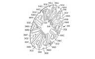
割出し盤40は、割出し盤40の底面の外周縁に沿って延びる10個の切欠きリテーナ298を有している。各切欠きリテーナ298は、センサパック38が割出し盤40の下方に配置されたとき、箔64の外周に沿って形成された切欠き300の一つおよびセンサパックのベース部68の外周に沿って形成された切欠き302の対応する一つに配置されるようになっている。切欠きリテーナ298が切欠き300および302の中に配置されると、センサパック38は割出し盤40上に保持され、センサキャビティ66A〜Jがそれぞれ割出し盤40の溝60A〜Jと一直線に並ぶ。したがって、切欠きリテーナ298ならびに切欠き300および302は、センサパック38が割出し盤40とともに回転するようにセンサパック38を割出し盤40上に保持することと、センサパック38を割出し盤40に対して円周方向に正しく並べて配置することとの二重の目的を有している。
【0042】
割出し盤40の下方に配置されたセンサパック38は、10個のセンサ70をセンサキャビティ66A〜Jのそれぞれに一つずつ収容するためのものである。センサキャビティ66Jのセンサ70に関して図5に示したように、各センサ70は、前端、すなわち試験端304から後端306まで延びるほぼ平坦な長方形である。前端304は角ばっており、センサ70がナイフ刃によってセンサキャビティ66Jから押し出されるときに、箔64の、センサキャビティ66Jにかぶさる未切断部を穿刺し、分析される血液の中に配置されるようになっている。センサ70の後端306は小さな切欠き308を含み、ナイフ刃62がセンサ70をセンサキャビティ66Jから放出するとき、この切欠きの中にナイフ刃62が配置される。
【0043】
切欠き308は、ナイフ刃62がセンサ70と接触するための標的区域を提供し、ナイフ刃62が切欠き308と接触したならば、センサ70はナイフ刃62に対して中心に配される。センサ70の後端306の近くの接点310は、センサ70が図4に示す試験位置にあるとき、センサアクチュエータ74の接触端72に設けられたセンサ接点246および250と嵌り合うようになっている。その結果、センサ70はプリント回路板76上の回路に結合され、試験中にセンサ70で生成された情報を記憶および/または解析することができるようになる。
【0044】
各センサ70には、センサ70の前端、すなわち試験端304からセンサ70中に配置された生体感知物質または試薬物質に延びる毛管通路が設けられている。センサ70の試験端304が流体(例えば、指を何かで穿刺したのち指先に溜る血液)の中に配置されると、その流体の一部が毛管作用によって毛管通路に引き込まれて、試験するのに十分な量の流体がセンサ70に引き込まれるようになる。そして、この流体はセンサ70中の試薬物質と化学反応を起こして、試験される血液中の血中グルコース濃度を示す電気信号が接点310に供給され、ひいては、センサアクチュエータ74を介してプリント回路板76に供給される。
【0045】
センサパック38は、円形のベース部68と、対応する形状の箔64とから形成されている。センサキャビティ66A〜Jがベース部68の凹みとして形成され、センサキャビティ66A〜Jのそれぞれがセンサ70の一つを収容するようになっている。センサキャビティ66Aに関して図6に示すように、センサキャビティ66A〜Jのそれぞれは、センサキャビティ66Aの内端314から外端316まで延びる底支持壁312を有している。この支持壁312は、内端314から外端316まで延びるにつれ、わずかに上向きに傾斜している。支持壁312のこの傾斜の結果として、センサ70がセンサキャビティ66A〜Jから放出されるとき、センサがわずかに持ち上げられて、箔64およびベース部68の外周に沿って箔64をベース部68に付着するヒートシールの部分を避ける、すなわちその上を通過するようになっている。
【0046】
センサキャビティ66A〜Jのそれぞれは、乾燥剤キャビティ318A〜Jの対応する一つと流体連通している。乾燥剤キャビティ318A〜Jのそれぞれは、ベース部68における、センサキャビティ66A〜Jの対応する一つに隣接する小さな凹みから形成されている。センサキャビティ66A〜Jが適当な湿度レベルに維持されることを保証するために、乾燥剤が乾燥剤キャビティ318A〜Jに配置されて、個々のセンサキャビティ66A〜Jに配置されたセンサ70中の試薬物質が使用の前に悪影響を受けることのないようにしている。乾燥剤は、小さな袋もしくは丸いビーズの物質または乾燥剤キャビティ318A〜Jに容易に配置することができる他いかなる形態であってもよい。乾燥剤キャビティ318A〜Jのそれぞれに配置するそのような乾燥剤の量は、センサキャビティ66A〜Jを乾燥状態に維持するのに要する量に依存するであろう。用いることができる乾燥剤の一つのタイプは、商品名NATRASORB の下で販売され、粉末、ペレットおよびビーズの形態で利用することができる。
【0047】
切欠き302がベース部68の外周縁に沿って形成されている。箔64がベース部68にシールされると、箔64の外周縁沿いの切欠き300が切欠き302と整合し、それにより、一体化した一連の切欠きを302をセンサパック38の外周縁に沿って形成する。切欠き300および302によって形成される各切欠きは、ベース部68のセンサキャビティ66A〜Jのそれぞれと関連して、センサパック38が割出し盤40に取り付けられ、同時に切欠きリテーナ298が切欠き300および302の中に配置されたとき、センサキャビティ66A〜Jがそれぞれ割出し盤40に設けられたまっすぐな溝60A〜Jの個々の溝と適切に適切に整合するようになる。
【0048】
箔64は、ベース部68の上面を覆い、箔64の外周縁全体をベース部68の外周縁に対してヒートシールすることにより、ベース部に取り付けられるようになっている。箔64はまた、センサ保持キャビティ66A〜Jと乾燥剤キャビティ318A〜Jとの各組の周囲でもヒートシールされてセンサ保持キャビティ66A〜Jおよび乾燥剤キャビティ318A〜Jをシールし、個々のセンサ70が乾燥状態に維持され、互いに隔離されるようにしている。その結果、センサキャビティ66A〜Jの一つの開封が他のセンサキャビティ66A〜Jのいずれの乾燥状態にも影響することはない。箔64は、センサ保持キャビティ66A〜Jおよび乾燥剤キャビティ318A〜Jを十分にシールし、同時に、センサ70がセンサキャビティ66A〜Jから押し出されるときに容易にナイフ刃62によって切断され、センサ70によって穿通されうる材料を提供するいかなる材料からなるものでもよい。箔64に使用することができる一つのタイプの箔は、Alusuisse Flexible Packaging社によって販売されているAL−191−01箔である。
【0049】
図8に示すように、ベース部68は、その下面の、センサキャビティ66A〜Jよりも内側にラベル区域320を含む。導電性ラベル322がこのラベル区域320に配置され、較正回路260によって感知することができる較正および製造の情報を提供する。
【0050】
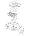
較正回路260は下側ケース36に位置している。較正回路260ならびに上側プレート324、接着リング326およびパッド328が、下側ケース36中の開口332を通って上側プレート324の開口に入るリテーナクリップ330により、下側ケース36中の位置に保持される。上側プレート324は内寄りの金属領域338を有し、残りの外寄り部分340はプラスチックである。較正回路260は、接着リング326によって上側プレート324に対して適切な周方向位置に維持されて、較正回路260から上向きに延びるプローブ342が内寄りの金属領域338の開口334の周囲に設けられた穴344と整合し、その中を通過するようになっている。
【0051】
ラッチ90によって下側ケース36を上側ケース34に掛け止めた状態でセンサ分与装置30を閉じると、プローブ342が、センサ分与装置30中で使用されているセンサパック38のラベル領域320に位置する導電性ラベル322と接触する。プローブ342が導電性ラベル322を適当な強さで押すことを保証するため、パッド328が可撓性の較正回路260の下に配置され、これがクッションを提供して、特にセンサパック38が割出し盤40によって回されるとき、プローブ342が互いに独立して動くことができるようにしている。その結果、ラベル322に含まれる較正および製造のデータのような情報をプローブ342を介して較正回路260に転送することができ、一方で較正回路が弾性コネクタ261を介してそのデータをプリント回路板76上の回路に結合する。そして、スライドラッチ110を横方向に動かし、スライドアクチュエータ42を前端48に向けて前方に動かすことによってセンサ分与装置30をその表示モードに入れたとき、情報をレンズ136越しに液晶表示ユニット138上に表示することができる。
【0052】
血中グルコースの試験にセンサ分与装置30を使用するためには、装置30を開けて、センサパック38を割出し盤40上の適切な位置に挿入しなければならない。装置30は、ラッチ90を、上側ケース34の前部100に設けられた凹み98の中のその掛止め位置から外すことによって開く。このようにしてラッチ90を解放した状態で、ピボットピン82を中心にして下側ケース36を上側ケース34から旋回させることができる。使用済みのセンサパック38があるならばそれを割出し盤40上のその位置から外し、切欠きリテーナ298をセンサパック38の外周沿いの切欠き300および302に配置することによって新たなセンサパック38を割出し盤40に配置することができる。このようにセンサパック38を割出し盤40に配置した状態で、各センサキャビティ66A〜Jは、ナイフスロット288の下方で、半径方向に延びるまっすぐな溝60A〜Jの一つと一直線に並ぶ。
【0053】
センサパック38を割出し盤40に配置した状態で、下側ケース36を上側ケース34に向けて旋回させることができる。ラッチ90がピン94上で枢転し、上側ケース34の前部100の凹み98に掛り止まって、下側ケース36が上側ケース34に対して閉じされる。下側ケース36と上側ケース34とを掛け止めて合わせると、較正回路260から上側プレート324の穴344を通って突出するプローブ342がセンサパック38のラベル区域320に位置するラベル322と係合する。その結果、ラベル322に含まれるセンサパック38に関する情報がコネクタ261を介してプリント回路板76上の回路に提供される。加えて、プローブ342によってセンサパック38の位置を検出して、センサパック38のセンサ70を試験目的に使用するときセンサパック38の回転位置を検出することができるようになる。
【0054】
上側ケース34と下側ケース36とを掛け止めて合わせた状態で、スライドラッチ110を操作すると、センサ分与装置30をその表示もしくはデータ処理モードまたはその試験モードのいずれかに入れることができる。例えば、スライドラッチ110を装置30の縦軸に対して横方向に動かすと、装置30をその表示モードに入れることができる。スライドラッチ110を横方向に動かすと、C字形のキャッチ122が動かされてスライドアクチュエータ42の開口126の横方向に延びる部分132に入る。スライドアクチュエータ42が前端48に向かって動く結果、スライドクリップ112の側面にあるモードアクチュエータ118上のカム面346が、開口158の中を延びるオン/オフスイッチ154のアクチュエータボタン348を押下して、それにより、常開スイッチ154を閉にする。スライドスイッチ110が横方向に動かされた状態では、モードアクチュエータ118は、開口160の中を延びるオン/オフスイッチ156のアクチュエータボタン350と接触しない。オン/オフスイッチ156が作動しないままオン/オフスイッチ154が閉になる結果、センサ分与装置30が作動してその表示モードに入る。スライドアクチュエータ42が前端48に向かって前方へ動く間、C字形のキャッチ122はスロット133の中で動いて、駆動装置150から延びるポスト130と係合しないようになる。その結果、駆動装置50は上側ケース34の後端46の近くのその待機位置にとどまる。
【0055】
スライドアクチュエータ42を前端48に向けて動かすと、スライドアクチュエータ42は上側ケース34の後部88の開口134から離れ、液晶表示ユニット138がレンズ136越しに見えるようになる。センサパック38および実施された試験に関する情報をこの液晶表示ユニット138上に表示することができる。表示される情報は、上側ケース34の後端46から突出するボタン143および146の作動によって決めることができる。ボタン143および146はまた、液晶表示ユニット138上の表示したがってプリント回路板76上の回路に情報を入力するのにも使用することができる。この情報が表示または入力されるとき、上側ケース34のスイッチ154および156に隣接する圧電アラーム352によって可聴インジケータが選択的に発される。
【0056】
センサ分与装置30の使用者が情報の取得またはデータの入力を完了すると、スライドアクチュエータ42を、上側ケース34の上壁104に形成された凹み102の中にスライドさせることにより、それを上側ケース34の後端46に向けて戻す。モードアクチュエータ118がアクチュエータボタン348を通過したのち、アクチュエータボタン348はもはや押下されず、オン/オフスイッチはその常開状態に戻る。そして、装置30はそのオフ状態、すなわち待機状態になる。スライドアクチュエータ42をその完全引込み位置に戻したならば、スライドアクチュエータ42は、スロット133の後端に隣接するところで凹み102から突出する戻止め354によってその位置に保持される。スライドアクチュエータ42がその完全引込み位置にある状態で、スライドアクチュエータ42は再び液晶表示ユニット138のレンズ136を覆い、スライドラッチ110を横方向に動かして、図1に示すその通常位置に戻すことができる。
【0057】
センサ分与装置30の主な用途は血中グルコース試験に関連する。このような試験を実施する場合、装置30の使用者は、スライドラッチ110上のこぶ120を押して、凹み中のスライドアクチュエータ42を後端46の近くのその待機位置から前端、すなわち試験端48に向けてスライドさせる。スライドアクチュエータ42を試験端48に向けて動かすとき、スライドクリップ112の側面のモードアクチュエータ118のカム面346が、開口158を通って延びるオン/オフスイッチ154のアクチュエータボタン348および開口160を通って延びるオン/オフスイッチ156のアクチュエータボタン350と接触し、それらを押下する。モードアクチュエータ118による両方のアクチュエータボタン348および350の押下が両方のオン/オフスイッチ154および156を閉にする。両方のオン/オフスイッチ154および156が閉になる結果、センサ分与装置30が作動してその試験モードに入る。
【0058】
スライドアクチュエータ42を前端48に向けて動かすとき、C字形のキャッチ122がスロット128に入って、駆動装置50から延びるポスト130と係合するようになる。その結果、駆動装置50は、スライドアクチュエータ42にとともに前端48に向けて動かされる。駆動装置50が後端46の近くのその待機位置にあるときには、カム従動子198が、駆動装置50中の拡大した凹み184、ナイフばね166中の拡大した凹み206およびハウジングガイド164中の開口234の中に延び、同様に、カム従動子200が、駆動装置50中の拡大した凹み184、ナイフばね166中の拡大した凹み206およびハウジングガイド164中の開口236の中に延びていた。その結果、カム従動子198および200は、カムトラック202および204それぞれのカム面202Aおよび204Aの後端に置かれていた。
【0059】
駆動装置50がスライドアクチュエータ42とともに前端48に向けて動かされるとき、カム従動子198および200がそれぞれ下向きに延びるカム面202Aおよび204Aに沿って移動して、ナイフ刃62が、ブロックガイド162の、カムトラック202と204との間に設けられたスロット268および割出し盤40上の、スロット268と一直線に並んだまっすぐな溝、例えば溝60Jのナイフスロット288にはまるようになる。カム従動子198および200がそれぞれカム面202Aおよび204Aに沿って移動するときナイフ刃62が続けて下向きに移動する結果、ナイフ刃62が、箔64のうち、センサキャビティ66A〜Jの、割出し盤40上の溝60Jと一直線に並んだ特定の一つ、例えばセンサキャビティ66Jを覆う部分を切断し始める。
【0060】
ナイフ刃62が箔64を切断するにつれ、ナイフ刃はセンサキャビティ66J中にさらにはまり、センサキャビティ66Jに収容されたセンサ70の後端306の切欠き308と係合する。駆動装置50、ひいてはナイフ刃62が前端48に向かって更に動くと、センサキャビティ66Jを覆う箔64がさらに切断され、センサ70の前端304が、傾斜した底支持壁312に載り上げ始める。これが起こるとき、カム従動子198が、上向きに傾斜したカム面202Bに沿って移動し始め、カム従動子200が、上向きに傾斜したカム面204Bに沿って移動し始めて、ナイフ刃62が、箔64のうち、センサキャビティ66Jにかぶさる部分を穿通しながら、キャビティ66Jから放出されつつあるセンサ70をその前端304で持ち上げる傾向を示すようになる。センサ70の前縁304は、尖った偏りのある形状であり、センサ70が、センサキャビティ66Jを覆う箔64を破るとき、センサ70の前縁304が、箔64を引き伸ばすだけでなく、それに出口を切り開けるようになっている。少なくとも一部には上向きに傾斜した支持壁312によって前端304が持ち上げられることが、センサ70の前端304が箔64の外周およびセンサパック38のベース部68の周囲のヒートシールを避けることを可能にする。そうでなければ、ヒートシールがセンサキャビティ66Jからのセンサ70の放出を妨げることになろう。
【0061】
スライドアクチュエータ42とともに駆動装置50が前進を続ける結果、センサ70がセンサキャビティ66Jから完全に放出される。センサ70がセンサキャビティ66Jから放出されたならば、センサ70は、図4に示すようにセンサ70の前端、すなわち試験端304が上側ケースの前端48から突出するまで、センサガイド270中のセンサスロット269およびそれと一直線に並んだラッチ90のセンサスロット271の中に案内される。センサ70がセンサスロット269および271の中を案内されるとき、駆動装置50の前縁186から突出するカム突起188および190がセンサアクチュエータ74の接触端72と係合し、それにより、接触端72をセンサアクチュエータガイド238に沿ってセンサ70に向けて下向きに押しやる。接触端72から延びるポスト254がセンサ70に押し当てられてセンサ70をセンサガイド270中に、センサスロット269および271から突出した状態に維持する。加えて、ポスト254の両側の接触端72から突出する可撓性のセンサ接点246および250がセンサ70上の接点310と電気的に接触して、センサ70上の接点310が接点246および250、センサアクチュエータ74の接触アーム242および244ならびにセンサアクチュエータ74の回路接触部240のリング接点248および252を介してプリント回路板76上の回路に結合されるようになっている。ポスト254のセンサ70に対する係合は、センサ70をその試験位置に締め付けるだけでなく、センサアクチュエータ74の接触端72をセンサ70から適当な距離だけ離して配置することにより、センサ接点246および250がセンサ接点310との間で所望の接触を成すことを保証する。
【0062】
駆動装置50が上側ケース34の前端48に向けて前方に動かされるとき、割出し盤駆動アーム54の遠位端のボタン58がブロックガイド162中のスロット272の中を割出し盤40に設けられたまっすぐな溝60E(すなわち、溝60Jに対して直径方向に反対側の溝)に沿って移動する。ボタン58が溝60E中をカム面285および286に沿って移動して段290および292を越えて相互接続された曲線状の溝80Eに入るため、割出し盤40は回転しない。
【0063】
センサ70がその試験位置に入り、スライドアクチュエータ42および駆動装置50がそれらの前方位置、すなわち試験位置に動かされたならば、ボタン58が曲線状の溝80Eの最内部分に配置され、カム従動子198および200がナイフばね166の坂路部214および216の前方に配置される。そして、センサ70の試験端304を流体、例えば人の指を何かで穿刺したのち指に溜る血液の中に配置することができる。流体はセンサ70の中に吸収され、センサ70中の中の試薬物質と化学反応を起こして、試験される血液中の血中グルコース濃度を示す電気信号が接点310に供給され、それにより、センサアクチュエータ74を介してプリント回路板76に供給される。
【0064】
血液分析試験が完了したならば、装置30の使用者がスライドリリース110から突出するこぶ120を押すことにより、スライドアクチュエータ42を上側ケース34の前端48から後端46に向けて動かす。スライドアクチュエータ42を後端46に動かすにつれ、駆動装置50の前縁186から突出するカム突起188および190がセンサアクチュエータ74の接触端72との係合位置から離れて、接触アームがブロックガイド162の支持面283および284の前方に延びるときのそれらの弾性により、接触端72がセンサから離れるようになる。ポスト254がもはやセンサ70に対して押し付けられていない状態で、グルコース試験に使用されたセンサ70をセンサスロット269および271から取り出し、廃棄することができる。
【0065】
駆動装置50が前端48から離れるとき、ナイフアセンブリ52上のカム従動子198が坂路部214に載り上げてナイフばね166のばね脚210に載り、ナイフアセンブリ52上のカム従動子200が坂路部216に載り上げてナイフばね166のばね脚212に載る。ナイフばね166はナイフアセンブリ52をピボットピン194および196を中心に上向きに旋回させて、ナイフ刃62が割出し盤40およびその下に取り付けられたセンサパック38から離れるようになっている。そのようにナイフ刃62が割出し盤40から離れた状態で、割出し盤40を回転させて、センサキャビティ66A〜Jの別の一つをブロックガイド162のスロット268と一直線に並べることができる。
【0066】
これに関して、スライドアクチュエータ42の後端46への引込みが、割出し盤駆動アーム54上のボタン58を溝80E中の下向きに傾斜した面294に沿って移動させる。湾曲した溝80Eにおけるこの動きが割出し盤40を回転させて、ボタン58が次のまっすぐな溝60Dに入るとき、次のまっすぐな溝60Iがブロックガイド162のスロット272の下で一直線に並ぶようになる。スライドアクチュエータ42が戻り止め354を越えてその完全引込み位置に達したならば、偏倚ばね56がナイフ刃アセンブリ52を下向きに押しやって、カム従動子198が、駆動装置50中の拡大した凹み184、ナイフばね166中の拡大した凹み206およびハウジングガイド164中の開口234の中に延び、同様に、カム従動子200が、駆動装置50中の拡大した凹み184、ナイフばね166中の拡大した凹み206およびハウジングガイド164中の開口236の中に延びるようになる。その結果、カム従動子198および200は、カムトラック202および204のそれぞれのカム面202Aおよび204Aの後端に置かれて、センサパック38中のセンサ70の別の一つをセンサパック38から放出し、別の試験手順に使用することができるようになる。
【0067】
例示した実施態様の詳細を参照しながら本発明を説明したが、そのような詳細は、請求の範囲に定める本発明の範囲を限定しようとするものではない。例えば、装置30は、血中グルコース以外の流体の試験に使用することもできる。実際、装置30は、試薬物質によって分析することができるものならば、いかなるタイプの化学物質流体の分析に関して使用することもできる。
【図面の簡単な説明】
【図1】本発明を具現化する血中グルコースセンサ分与装置の斜視図である。
【図2】図1の血中グルコースセンサ分与装置の平面図である。
【図3】図1の血中グルコースセンサ分与装置の底面図である。
【図4】図1の血中グルコースセンサ分与装置を、センサが試験位置にある状態で示す斜視図である。
【図5】図1の血中グルコースセンサ分与装置に使用されるセンサパックを、センサパックの箔部をセンサパックのベース部から離した状態で示す分解斜視図である。
【図6】図5のセンサパックのベース部の上面図である。
【図7】図5のセンサパックのベース部の側面図である。
【図8】図5のセンサパックのベース部の底面図である。
【図9】図1のセンサ分与装置の構成部品の分解斜視図である。
【図10】図1のセンサ分与装置の構成部品の分解斜視図である。
【図11】図1のセンサ分与装置の構成部品の分解斜視図である。
【符号の説明】
30 センサ分与装置
38 センサパック
40 割出し盤
50 駆動装置
66 センサキャビティ
70 センサ
74 センサアクチュエータ
76 プリント回路板[0001]
BACKGROUND OF THE INVENTION
The present invention relates generally to fluid monitoring systems, and more particularly to a new and improved apparatus for handling multiple sensors used to analyze blood glucose or other analytes contained therein. .
[0002]
[Prior art]
People with various symptoms of diabetes must routinely test their blood to determine blood glucose levels. The results of such tests can be used to determine what insulin or other drug needs to be administered. One type of blood glucose test system uses a sensor to test a blood sample.
[0003]
Such a sensor can be a generally flat rectangle with a front end, ie, a test end, and a rear end, ie, a contact end. The sensor contains a biosensing or reagent material that reacts with blood glucose. The test end of the sensor is arranged in the fluid to be tested, for example in the blood that accumulates on the finger after puncturing the finger with something. The fluid is drawn by capillary action into a capillary passage extending through the sensor from the test end to the reagent material, so that a sufficient amount of fluid is drawn into the sensor for testing. The fluid then chemically reacts with the reagent substance in the sensor so that an electrical signal indicating the blood glucose concentration in the blood being tested is present at the rear end of the sensor, i.e. the contact area located near the contact end. Supplied.
[0004]
In order to couple the electrical signal generated at the sensor contacts to the monitoring device, the sensor must be inserted into the sensor holder before the end of the sensor is placed in the fluid to be tested. The holder has a corresponding mating contact area that is coupled to a contact on the sensor when the sensor is inserted into the holder. As a result, the holder serves as an interface between the sensor and a monitoring device that stores and / or analyzes the test results.
[0005]
Prior to use, the sensor must be maintained at an appropriate humidity level to ensure maintenance of the integrity of the reagent material in the sensor. The sensors can be packaged one by one in a tear-away package so that they can be maintained at an appropriate humidity level. For example, a blister type packaging method may be used. In this regard, the package can include a desiccant to maintain an appropriate humidity or dry level in the package. In order to use individual sensors to test blood glucose, the package must be opened by tearing off the seal. Alternatively, some packages require the user to apply a force against one side of the package, resulting in a rupture or tear of the sensor on the opposite side of the package foil. As can be appreciated, opening these packages can be difficult. In addition, once the package has been opened, the user must place the sensor in the sensor holder and the sensor is not damaged or contaminated when used to test a blood sample. Must be confirmed.
[0006]
[Problems to be solved by the invention]
Accordingly, it is an object of the present invention to provide a new and improved sensor pack for multiple sensors used to test blood glucose and a dispensing device for handling the sensors contained in such sensor packs. There is. In particular, an object of the present invention is to accept a sensor pack that includes a plurality of fluid sensors and selectively place individual sensors in the test position when the feed actuator on the sensor dispensing device is moved to the test position. A new and improved fluid that allows the sensor pack to be automatically indexed and another one of the sensors to be placed in the test position while the feed actuator is returned to its standby position A sensor dispensing device handling device is provided, having a cutting device pivotally mounted on a drive device, the cutting device discharging a sensor from a sensor pack and placing the released sensor in a test position, A new and improved fluid sensor dispensing device is provided that is adapted to move away from the sensor pack when the drive device is returned to the standby position, and includes a plurality of individual sensor sensors. Providing a new and improved fluid sensor dispensing device having a sensor pack having cavities, each cavity having a support surface for facilitating the release of the sensor from the sensor cavity. A novel and improved fluid sensor dispensing device is provided that provides a contact device for coupling to a data processing device in a sensor dispensing device to allow display of data from individual sensors. A calibration mechanism located in the hinged part of the dispenser, which interacts with a data processing device provided in another hinged part of the dispenser by a somewhat flexible connector located in a tortuous path A new and improved fluid sensor dispensing device having a connected calibration mechanism is provided, which fits into a notch provided in the sensor pack and breaks the sensor pack. And properly positioned relative to the apparatus, the sensor pack is to provide a fluid sensor dispensing instrument having a new and improved with a retention device to ensure that rotates with indexing device.
[0007]
[Means for Solving the Problems]
In accordance with the above objects and many other objects of the present invention, the present invention is embodied in a sensor dispensing device adapted to receive a sensor pack including a plurality of blood glucose sensors. Each sensor is a generally flat rectangle with a front test end through which fluid is drawn to react with the reagent material in the sensor and a rear contact end on the opposite side. The sensor pack includes a generally circular base portion in which a sensor holding cavity or recess is formed. Each sensor holding cavity is adapted to receive one of the sensors and is in fluid communication with a corresponding desiccant cavity in which the desiccant is located. The desiccant is placed in the cavity to ensure that the corresponding sensor cavity is maintained at an appropriate humidity or dry level so that the reagent material in the sensor is not adversely affected before the sensor is used. ing. The foil is heat sealed to the base portion over the entire outer periphery of the base portion and over the outer periphery of each set of sensor holding cavities and desiccant cavities to seal the sensor holding cavities and desiccant cavities, Individual sensors are kept dry and separated from each other. As a result, opening one sensor cavity does not affect the dryness of any other sensor cavity.
[0008]
Each sensor cavity has a support wall, and individual sensors rest on the support wall when the sensor is placed in the sensor cavity. The support wall extends in a radial direction from a position adjacent to the periphery of the base portion toward the center of the base portion. In order to assist the discharge of the sensor from the sensor cavity, the support wall includes an inclined portion that is inclined in a direction toward the peripheral edge of the base portion toward the foil that seals the base portion. The sensor pack further includes a series of notches formed along the outer periphery of the sensor pack, each corresponding to one sensor cavity.
[0009]
The sensor device includes an outer housing having an upper case and a lower case, the upper case and the lower case can pivot in a clamshell manner relative to each other, and the sensor pack is disposed in and within the housing It can be placed on the index board. With the sensor pack loaded in the housing, a slide latch on the slide actuator located in the upper case of the housing controls whether the movement of the slide actuator puts the device into display or data processing mode or test mode.
[0010]
When the slide latch is moved sideways and the slide actuator is moved away from its standby position, the device enters its display mode. When in the display mode, the person using the device can view the data displayed on the display unit of the upper case, or can input the data to the device.
[0011]
When the slide latch is in its normal position and the slide actuator is pushed toward its test position, the device enters its test mode. The feed mechanism that engages the slide actuator in the upper case of the housing is also moved from its standby position toward the test position. The feed mechanism includes a drive device, on which a knife blade is pivotally attached, and an indexing plate drive arm extends from the drive device. When the slide actuator is moved towards its starting position, the drive with the knife blade on top moves towards the test position of the feed mechanism, and the indexing board drive arm extends straight through the indexing board. When the feed mechanism moves toward the test position, the indexing plate does not rotate. The knife blade has a cam follower that rests on a first portion of the cam track under a lift spring when the drive begins to move away from its standby position. The first part of the track is inclined towards the sensor pack so that the knife blade moves towards one of the sensor cavities of the sensor pack arranged on the indexing board. The knife blade penetrates a foil covering the sensor cavity aligned with the knife blade and engages a sensor disposed in the cavity. When the slide actuator and drive are pushed towards the actuator operating position, the knife blade further cuts the foil covering the sensor cavity and pushes or releases the sensor out of the sensor cavity, before the sensor is biased The edges will break through the outer foil covering the sensor cavity. When the sensor is pushed out of the sensor cavity, it moves along the inclined support wall of the sensor cavity and heat seals that secure the foil to the base of the sensor pack as the sensor is advanced by the knife blade You don't have to be pushed into it. The force required to move the sensor into the foil is minimized by the pointed biased shape of the front of the sensor so that the sensor cuts an exit hole in it rather than simply stretching the foil. Become.
[0012]
As a result of the continuation of the slide actuator towards its test position, the sensor is completely released from the sensor cavity. A guide located near the test end of the sensor housing guides the sensor exiting the sensor cavity to the test position. When this happens, the cam surface at the front of the drive engages a sensor actuator that maintains the sensor in its test position with the test end of the sensor protruding from the test end of the housing. The sensor actuator includes a contact that mates with a corresponding contact on the sensor. The sensor dispensing device may include a microprocessor or other data processing circuit that is also electrically coupled to the sensor actuator, and may process data obtained from the sensor when the sensor is inserted into the blood being tested. It can be done. The processed data can then be displayed on the screen of the upper case of the device or stored for use in other analytical instruments.
[0013]
When the blood analysis test is complete, the slide actuator is moved in the opposite direction toward its standby position. When the slide actuator moves away from its test position, the drive moves away from the sensor actuator, allowing the contacts on the sensor actuator to move away from the corresponding contacts on the sensor and remove the sensor from the dispensing device. As the drive device continues to retract, the cam follower on the knife assembly rests on the lift spring, the knife blade moves away from the sensor pack, and the indexer advances the sensor pack. In this regard, the indexing disc drive arm extending from the drive begins to move along a curvilinearly extending groove interconnected to a radially extending groove in the indexing disc, resulting in rotation of the indexing disc. Bring. Also, the rotation of the indexing board results in the rotation of the sensor pack so that the next one of the sensor cavities is placed in line with the knife blade and the sensor in the sensor cavity should be implemented next. It can be used for blood glucose test.
[0014]
The dispensing device includes a calibration circuit having a probe that contacts a label on the sensor pack when the sensor pack is attached to the indexing board. The calibration circuit provides data to the data processor regarding the tests performed with the sensor pack and the sensors in the sensor pack.
[0015]
DETAILED DESCRIPTION OF THE INVENTION
The present invention, together with the above and other objects and advantages, can be clearly understood from the following detailed description of embodiments of the invention illustrated in the drawings.
[0016]
Referring initially to the drawings, there is shown a blood glucose sensor dispensing device embodying the present invention indicated by
[0017]
The
[0018]
After the
[0019]
When the blood analysis test is complete, the
[0020]
As can be seen in FIGS. 1 to 4 and FIGS. 9 to 11, the
[0021]
The
[0022]
Movement of the
[0023]
When the
[0024]
The
[0025]
[0026]
Two
[0027]
A block guide 162, a printed
[0028]
As previously indicated, when the
[0029]
The
[0030]
In order to extend the
[0031]
The driving
[0032]
[0033]
As indicated above, the
[0034]
The
[0035]
Block guide 162 includes cam tracks 202 and 204. Cam tracks 202 and 204 are located side by side with respect to
[0036]
Another
[0037]
The block guide 162 includes mounting holes 274-277 through which fasteners 168-171 extend to attach the block guide 162 to the appropriate location on the
[0038]
As previously indicated, the
[0039]
Grooves 60A-J are straight, radially extending grooves, so that
[0040]
As shown in FIG. 10 for the
[0041]
The
[0042]
The
[0043]
The
[0044]
Each
[0045]
The
[0046]
Each of the
[0047]
A
[0048]
The
[0049]
As shown in FIG. 8, the
[0050]
The
[0051]
When the
[0052]
In order to use the
[0053]
With the
[0054]
When the
[0055]
When the
[0056]
When the user of the
[0057]
The primary use of
[0058]
As the
[0059]
When the
[0060]
As the
[0061]
As a result of the
[0062]
When the
[0063]
If
[0064]
When the blood analysis test is completed, the user of the
[0065]
When the
[0066]
In this regard, retraction of the
[0067]
Although the invention has been described with reference to details of the illustrated embodiments, such details are not intended to limit the scope of the invention as defined in the claims. For example, the
[Brief description of the drawings]
FIG. 1 is a perspective view of a blood glucose sensor dispensing apparatus embodying the present invention.
2 is a plan view of the blood glucose sensor dispensing device of FIG. 1. FIG.
3 is a bottom view of the blood glucose sensor dispensing device of FIG. 1. FIG.
4 is a perspective view showing the blood glucose sensor dispensing device of FIG. 1 with the sensor in a test position. FIG.
5 is an exploded perspective view showing the sensor pack used in the blood glucose sensor dispensing device of FIG. 1 in a state where the foil portion of the sensor pack is separated from the base portion of the sensor pack. FIG.
6 is a top view of a base portion of the sensor pack of FIG. 5. FIG.
7 is a side view of a base portion of the sensor pack of FIG. 5. FIG.
8 is a bottom view of the base portion of the sensor pack of FIG. 5. FIG.
9 is an exploded perspective view of components of the sensor dispensing device of FIG. 1. FIG.
10 is an exploded perspective view of components of the sensor dispensing device of FIG. 1. FIG.
FIG. 11 is an exploded perspective view of components of the sensor dispensing device of FIG.
[Explanation of symbols]
30 sensor dispenser
38 sensor pack
40 Indexing board
50 Drive unit
66 Sensor cavity
70 sensors
74 Sensor actuator
76 Printed circuit board
Claims (27)
Translated fromJapanese外側ハウジングと、
複数のセンサ保持手段を有するセンサパックであって、センサ保持手段のそれぞれが、該複数の流体センサの一つを収容するようになっており、包囲手段によって少なくとも部分的に包囲され、該センサ保持手段の一つが送り位置に配されるような方法で該ハウジング中に配置されるセンサパックと、
該ハウジング中に配置され、第一の位置と第二の位置との間を動くことができ、その上に旋回自在に取り付けられた切断手段を有する駆動装置手段であって、該駆動装置手段が該第一の位置から該第二の位置に向けて動かされるとき、該切断手段が、該ハウジング中に配置されたカムトラックに載り上げて、該複数のセンサ保持手段のうち、該送り位置にある一つに向かって動かされて、該包囲手段を穿通し、該センサ保持手段中に配置された該センサと係合し、該センサを該センサ保持手段から試験位置に進める駆動装置手段と、
該センサを該試験位置に保持するための保持手段と、を含むことを特徴とするセンサ分与装置。In a sensor dispensing device that handles multiple fluid sensors,
An outer housing;
A sensor pack having a plurality of sensor holding means, wherein each of the sensor holding means is adapted to receive one of the plurality of fluid sensors and is at least partially enclosed by the surrounding means, the sensor holding means A sensor pack arranged in the housing in such a way that one of the means is arranged in the feeding position;
Drive means disposed in the housing and movable between a first position and a second position and having a cutting means pivotably mounted thereon, the drive means means When moved from the first position toward the second position, the cutting means is mounted on a cam track disposed in the housing, and is moved to the feeding position among the plurality of sensor holding means. A drive means that is moved towards one, pierces the surrounding means, engages the sensor disposed in the sensor holding means, and advances the sensor from the sensor holding means to a test position;
Sensor dispensingdevice characterized by includinga holding means for holding the sensor to the test position.
外側ハウジングと、
複数のセンサ保持手段を有するセンサパックであって、センサ保持手段のそれぞれが、該複数の流体センサの一つを収容するようになっており、包囲手段によって少なくとも部分的に包囲されているセンサパックと、
該ハウジング中に取り付けられた割出し手段であって、該センサパックが該割出し手段上に配置されて、該割出し手段が進められるとき、該センサ保持手段の一つが送り位置に配されるような方法で進められる割出し手段と、
該ハウジング中に配置され、第一の位置と第二の位置との間を動くことができる送り手段であって、該送り手段が、該第一の位置から該第二の位置に向けて動かされるとき、該包囲手段を穿通して、該複数のセンサ保持手段のうち、該送り位置にある一つに入り、該センサを該センサ保持手段から試験位置に進める送り手段と、
該送り手段が該第一の位置に戻されるときに該割出し手段を進めて該複数のセンサ保持手段の別の一つを該送り位置に配置するための、該送り手段および該割出し手段に接続した割出し駆動手段と、を含むことを特徴とする装置。In a sensor dispensing device for handling a plurality of fluid sensors,
An outer housing;
A sensor pack having a plurality of sensor holding means,the sensor pack respective sensor holding means, which is at least partially surrounded by it and, enclosing means to accommodate a single fluid the plurality of sensors When,
Indexing means mounted in the housing, wherein when the sensor pack is disposed on the indexing meansand the indexing means is advanced, one of the sensor holding means is disposed in the feed positionIndexing means that can be advanced in such a way,
Disposed in the housing,a feeding means which is movable between a first position and a second position,該送Ri means, moved toward said second position from said first position A feed means that penetrates the surrounding means, enters one of the plurality of sensor holding means at thefeed position, and advances the sensor from the sensor hold means to a test position;
The feeding means and the indexing means for advancing the indexing means when the feeding means is returned to the first position to place another one of the plurality of sensor holding means at the feeding positionapparatus characterized by includinga indexing drive means connected to.
センサ分与装置のハウジング中に配置された割出し手段にセンサパックを設置して、複数のセンサ保持手段のうち、包囲手段によって包囲され、該複数の流体センサの一つを収容する一つが送り位置に来るようにし、
送りアクチュエータ手段を作動させて、送り手段を該センサ保持手段に対して該送り位置に進め、該送り手段が該包囲手段の一部を穿通し、該センサ保持手段中に配置された該センサと係合して、該センサ保持手段中の該センサを該センサ保持手段から外に進めて試験位置に配するようにし、
該送りアクチュエータ手段を待機位置に戻して、該送り手段を待機位置に戻し、それと同時に該割出し手段を進めて、該送りアクチュエータ手段を該待機位置に戻すとき該複数のセンサ保持手段の別の一つを該送り位置に動かすようにすることを特徴とする方法。In a method of handling a plurality of fluid sensors,
A sensor pack is installed in the indexing means arranged in the housing of the sensor dispensing device, and one of the plurality of sensor holding means is surrounded by the surrounding means and one of the plurality of fluid sensors is fed. To be in position,
Actuating a feed actuator means to advance the feed means to the feed position relative to the sensor holding means, the feed means penetrating a portion of the enclosing means, and the sensor disposed in the sensor holding means; Engaging the sensor in the sensor holding means out of the sensor holding means and placing it in the test position;
When the feed actuator means is returned to the standby position, the feed means is returned to the standby position, and at the same time, the indexing means is advanced to return the feed actuator means to the standby position. Moving one to the feed position.
複数のセンサキャビティを有するベース部であって、センサキャビティのそれぞれが該ベース部の周縁に向かって延び、該複数の流体センサの一つを収容するところのベース部と、
該ベース部に対してシールされて、該センサを中に配置した状態で該センサキャビティをシールする包囲手段と、
該センサが配置されている該センサキャビティのそれぞれにおける支持壁であって、該ベース部の周縁に隣接するところから該ベース部の中心に向かって半径方向に延び、該ベース部の該周縁に向かう方向に、該包囲手段に向かって傾斜している支持壁とを含むことを特徴とするセンサパック。In a sensor pack for use in a sensor device for handling a plurality of fluid sensors,
A base portion having a plurality of sensor cavities, each of the sensor cavities extending toward a periphery of the base portion and containing one of the plurality of fluid sensors;
Enclosing means sealed to the base and sealing the sensor cavity with the sensor disposed therein;
A support wall in each of the sensor cavities in which the sensors are disposed, extending radially from the vicinity of the periphery of the base portion toward the center of the base portion and toward the periphery of the base portion And a support wall inclined in the direction towards the surrounding means.
複数のセンサキャビティを有するベース部であって、センサキャビティのそれぞれが該ベース部の周縁に向かって延び、該複数の流体センサの一つを収容するところのベース部と、
該ベース部に対してシールされて、該センサを中に配置した状態で該センサキャビティをシールする包囲手段と、
該ベース部および該包囲手段の外周縁に沿って設けられた割出し切欠きであって、該センサパックを該センサ分与装置中に適切に配置するために、該センサパック上に該複数のセンサキャビティのそれぞれに対して配置されている割出し切欠きとを含むことを特徴とするセンサパック。In a sensor pack for use in a sensor device for handling a plurality of fluid sensors,
A base portion having a plurality of sensor cavities, each of the sensor cavities extending toward a periphery of the base portion and containing one of the plurality of fluid sensors;
Enclosing means sealed to the base and sealing the sensor cavity with the sensor disposed therein;
An index notch provided along an outer peripheral edge of the base portion and the surrounding means, wherein the plurality of the sensor packs are arranged on the sensor pack in order to properly position the sensor pack in the sensor dispensing device. A sensor pack comprising an index cutout disposed for each of the sensor cavities.
Applications Claiming Priority (2)
| Application Number | Priority Date | Filing Date | Title |
|---|---|---|---|
| US08/404,303US5630986A (en) | 1995-01-13 | 1995-03-14 | Dispensing instrument for fluid monitoring sensors |
| US08/404303 | 1995-03-14 |
Publications (2)
| Publication Number | Publication Date |
|---|---|
| JPH08262026A JPH08262026A (en) | 1996-10-11 |
| JP3718550B2true JP3718550B2 (en) | 2005-11-24 |
Family
ID=23599072
Family Applications (1)
| Application Number | Title | Priority Date | Filing Date |
|---|---|---|---|
| JP00108696AExpired - LifetimeJP3718550B2 (en) | 1995-03-14 | 1996-01-09 | Dispensing device for fluid monitor sensor |
Country Status (11)
| Country | Link |
|---|---|
| US (2) | US5630986A (en) |
| EP (1) | EP0732590B1 (en) |
| JP (1) | JP3718550B2 (en) |
| KR (1) | KR100394899B1 (en) |
| AT (1) | ATE263376T1 (en) |
| AU (1) | AU706347B2 (en) |
| CA (1) | CA2167109C (en) |
| DE (1) | DE69631992T2 (en) |
| DK (1) | DK0732590T3 (en) |
| ES (1) | ES2217291T3 (en) |
| TW (1) | TW386026B (en) |
Families Citing this family (300)
| Publication number | Priority date | Publication date | Assignee | Title |
|---|---|---|---|---|
| CA2170560C (en)* | 1995-04-17 | 2005-10-25 | Joseph L. Moulton | Means of handling multiple sensors in a glucose monitoring instrument system |
| US7235056B2 (en) | 1996-05-17 | 2007-06-26 | Amira Medical | Body fluid sampling device and methods of use |
| US20020010406A1 (en) | 1996-05-17 | 2002-01-24 | Douglas Joel S. | Methods and apparatus for expressing body fluid from an incision |
| US7828749B2 (en) | 1996-05-17 | 2010-11-09 | Roche Diagnostics Operations, Inc. | Blood and interstitial fluid sampling device |
| EP1579814A3 (en) | 1996-05-17 | 2006-06-14 | Roche Diagnostics Operations, Inc. | Methods and apparatus for sampling and analyzing body fluid |
| US7666150B2 (en)* | 1996-05-17 | 2010-02-23 | Roche Diagnostics Operations, Inc. | Blood and interstitial fluid sampling device |
| US5660791A (en)* | 1996-06-06 | 1997-08-26 | Bayer Corporation | Fluid testing sensor for use in dispensing instrument |
| US5856195A (en)* | 1996-10-30 | 1999-01-05 | Bayer Corporation | Method and apparatus for calibrating a sensor element |
| US6027459A (en)* | 1996-12-06 | 2000-02-22 | Abbott Laboratories | Method and apparatus for obtaining blood for diagnostic tests |
| AU6157898A (en) | 1997-02-06 | 1998-08-26 | E. Heller & Company | Small volume (in vitro) analyte sensor |
| IL123182A (en)* | 1997-04-28 | 2001-01-28 | Bayer Ag | Dispensing instrument for fluid monitoring sensors |
| DE69811268T2 (en)* | 1997-11-28 | 2003-07-10 | Provalis Dianostics Ltd | SYSTEM AND APPARATUS FOR CARRYING OUT AN ASSAY PROCEDURE |
| US6036924A (en) | 1997-12-04 | 2000-03-14 | Hewlett-Packard Company | Cassette of lancet cartridges for sampling blood |
| US7494816B2 (en)* | 1997-12-22 | 2009-02-24 | Roche Diagnostic Operations, Inc. | System and method for determining a temperature during analyte measurement |
| US7390667B2 (en) | 1997-12-22 | 2008-06-24 | Roche Diagnostics Operations, Inc. | System and method for analyte measurement using AC phase angle measurements |
| US8071384B2 (en) | 1997-12-22 | 2011-12-06 | Roche Diagnostics Operations, Inc. | Control and calibration solutions and methods for their use |
| US6645368B1 (en) | 1997-12-22 | 2003-11-11 | Roche Diagnostics Corporation | Meter and method of using the meter for determining the concentration of a component of a fluid |
| US7407811B2 (en) | 1997-12-22 | 2008-08-05 | Roche Diagnostics Operations, Inc. | System and method for analyte measurement using AC excitation |
| US6830731B1 (en)* | 1998-01-05 | 2004-12-14 | Biosite, Inc. | Immunoassay fluorometer |
| US6103033A (en) | 1998-03-04 | 2000-08-15 | Therasense, Inc. | Process for producing an electrochemical biosensor |
| US6391005B1 (en) | 1998-03-30 | 2002-05-21 | Agilent Technologies, Inc. | Apparatus and method for penetration with shaft having a sensor for sensing penetration depth |
| AU753745B2 (en)* | 1998-04-24 | 2002-10-24 | Roche Diagnostics Gmbh | Storage container for analytical devices |
| US7416699B2 (en) | 1998-08-14 | 2008-08-26 | The Board Of Trustees Of The Leland Stanford Junior University | Carbon nanotube devices |
| US6187000B1 (en)* | 1998-08-20 | 2001-02-13 | Endius Incorporated | Cannula for receiving surgical instruments |
| US6338790B1 (en)* | 1998-10-08 | 2002-01-15 | Therasense, Inc. | Small volume in vitro analyte sensor with diffusible or non-leachable redox mediator |
| DE19902601A1 (en)* | 1999-01-23 | 2000-07-27 | Roche Diagnostics Gmbh | Method and device for removing analytical consumables from a storage container |
| AU6210199A (en)* | 1999-09-27 | 2001-04-30 | Hypoguard Limited | Test device |
| JP4621860B2 (en)* | 2000-02-23 | 2011-01-26 | アークレイ株式会社 | Sensor cartridge, sensor supply device, and measurement device |
| DE10010694A1 (en)* | 2000-03-04 | 2001-09-06 | Roche Diagnostics Gmbh | Lancet including tipped needle with body surrounding tip |
| US6428664B1 (en)* | 2000-06-19 | 2002-08-06 | Roche Diagnostics Corporation | Biosensor |
| EP1365974A2 (en)* | 2000-07-03 | 2003-12-03 | Kodiak Technologies, Inc. | Thermal container with data monitoring system |
| GB0017737D0 (en)* | 2000-07-20 | 2000-09-06 | Hypoguard Limited | Test device |
| US7138089B2 (en) | 2000-07-20 | 2006-11-21 | Hypoguard Limited | Test device for analyzing blood glucose or other analytes in bodily fluids |
| US6488828B1 (en)* | 2000-07-20 | 2002-12-03 | Roche Diagnostics Corporation | Recloseable biosensor |
| US7875975B2 (en)* | 2000-08-18 | 2011-01-25 | Polyic Gmbh & Co. Kg | Organic integrated circuit completely encapsulated by multi-layered barrier and included in RFID tag |
| JP2004507096A (en)* | 2000-08-18 | 2004-03-04 | シーメンス アクチエンゲゼルシヤフト | Organic field effect transistor (OFET), method of manufacturing the organic field effect transistor, integrated circuit formed from the organic field effect transistor, and use of the integrated circuit |
| GB0021219D0 (en)* | 2000-08-30 | 2000-10-18 | Hypoguard Ltd | Test device |
| US6827899B2 (en) | 2000-08-30 | 2004-12-07 | Hypoguard Limited | Test device |
| GB0021887D0 (en)* | 2000-09-06 | 2000-10-18 | Provalis Diagnostics Ltd | Assay device |
| DE10044842A1 (en)* | 2000-09-11 | 2002-04-04 | Siemens Ag | Organic rectifier, circuit, RFID tag and use of an organic rectifier |
| WO2002025750A1 (en)* | 2000-09-22 | 2002-03-28 | Siemens Aktiengesellschaft | Electrode and/or conductor track for organic components and production method therefor |
| DE10053974A1 (en) | 2000-10-31 | 2002-05-29 | Roche Diagnostics Gmbh | Blood collection system |
| US8641644B2 (en) | 2000-11-21 | 2014-02-04 | Sanofi-Aventis Deutschland Gmbh | Blood testing apparatus having a rotatable cartridge with multiple lancing elements and testing means |
| DE10061299A1 (en)* | 2000-12-08 | 2002-06-27 | Siemens Ag | Device for determining and / or forwarding at least one environmental influence, production method and use thereof |
| DE10061297C2 (en)* | 2000-12-08 | 2003-05-28 | Siemens Ag | Procedure for structuring an OFET |
| WO2002056751A2 (en)* | 2001-01-22 | 2002-07-25 | Roche Diagnostics Gmbh | Lancet device having capillary action |
| DE10105914C1 (en)* | 2001-02-09 | 2002-10-10 | Siemens Ag | Organic field effect transistor with photo-structured gate dielectric and a method for its production |
| US20040094771A1 (en)* | 2001-03-26 | 2004-05-20 | Adolf Bernds | Device with at least two organic electronic components and method for producing the same |
| EP1399059B1 (en)* | 2001-05-18 | 2006-08-30 | Polymer Technology Systems, Inc. | Body fluid test apparatus with detachably mounted portable tester |
| DE10126860C2 (en)* | 2001-06-01 | 2003-05-28 | Siemens Ag | Organic field effect transistor, process for its manufacture and use for the construction of integrated circuits |
| US20020188223A1 (en) | 2001-06-08 | 2002-12-12 | Edward Perez | Devices and methods for the expression of bodily fluids from an incision |
| US6988996B2 (en) | 2001-06-08 | 2006-01-24 | Roche Diagnostics Operatons, Inc. | Test media cassette for bodily fluid testing device |
| US8337419B2 (en) | 2002-04-19 | 2012-12-25 | Sanofi-Aventis Deutschland Gmbh | Tissue penetration device |
| US7749174B2 (en) | 2001-06-12 | 2010-07-06 | Pelikan Technologies, Inc. | Method and apparatus for lancet launching device intergrated onto a blood-sampling cartridge |
| JP4209767B2 (en) | 2001-06-12 | 2009-01-14 | ペリカン テクノロジーズ インコーポレイテッド | Self-optimized cutting instrument with adaptive means for temporary changes in skin properties |
| US7344507B2 (en) | 2002-04-19 | 2008-03-18 | Pelikan Technologies, Inc. | Method and apparatus for lancet actuation |
| WO2005001418A2 (en) | 2003-05-30 | 2005-01-06 | Pelikan Technologies, Inc. | Method and apparatus for body fluid sampling and analyte sensing |
| US7981056B2 (en) | 2002-04-19 | 2011-07-19 | Pelikan Technologies, Inc. | Methods and apparatus for lancet actuation |
| EP1395185B1 (en) | 2001-06-12 | 2010-10-27 | Pelikan Technologies Inc. | Electric lancet actuator |
| US9795747B2 (en) | 2010-06-02 | 2017-10-24 | Sanofi-Aventis Deutschland Gmbh | Methods and apparatus for lancet actuation |
| US7041068B2 (en) | 2001-06-12 | 2006-05-09 | Pelikan Technologies, Inc. | Sampling module device and method |
| JP4272051B2 (en) | 2001-06-12 | 2009-06-03 | ペリカン テクノロジーズ インコーポレイテッド | Blood sampling apparatus and method |
| US9226699B2 (en) | 2002-04-19 | 2016-01-05 | Sanofi-Aventis Deutschland Gmbh | Body fluid sampling module with a continuous compression tissue interface surface |
| US7001344B2 (en)* | 2001-06-12 | 2006-02-21 | Pelikan Technologies, Inc. | Blood sampling device with diaphragm actuated lancet |
| WO2002101359A2 (en)* | 2001-06-12 | 2002-12-19 | Pelikan Technologies, Inc. | Integrated blood sampling analysis system with multi-use sampling module |
| US9427532B2 (en) | 2001-06-12 | 2016-08-30 | Sanofi-Aventis Deutschland Gmbh | Tissue penetration device |
| AU2002344825A1 (en) | 2001-06-12 | 2002-12-23 | Pelikan Technologies, Inc. | Method and apparatus for improving success rate of blood yield from a fingerstick |
| US20030021729A1 (en)* | 2001-07-26 | 2003-01-30 | Bayer Corporation | Removable cover for a glucose meter |
| US7611899B2 (en)* | 2001-08-13 | 2009-11-03 | Bayer Healthcare Llc | Sensor release for a sensor dispensing instrument |
| AU2002300223B2 (en)* | 2001-08-13 | 2008-12-11 | Bayer Corporation | Mechanical Mechanism for a Blood Glucose Sensor Dispensing Instrument |
| US7323141B2 (en)* | 2001-08-13 | 2008-01-29 | Bayer Healthcare Llc | Button layout for a testing instrument |
| US6661647B2 (en) | 2001-08-13 | 2003-12-09 | Bayer Corporation | Snap-in display frame |
| US20030031595A1 (en)* | 2001-08-13 | 2003-02-13 | Kirchhevel G. Lamar | Blood glucose sensor dispensing instrument having a modular electronics assembly |
| US7279130B2 (en)* | 2001-08-13 | 2007-10-09 | Bayer Healthcare Llc | Sensor dispensing instrument having an activation mechanism and methods of using the same |
| US7723113B2 (en)* | 2001-08-20 | 2010-05-25 | Bayer Healthcare Llc | Packaging system for test sensors |
| US7264627B2 (en)* | 2001-08-29 | 2007-09-04 | Roche Diagnostics Operations, Inc. | Wicking methods and structures for use in sampling bodily fluids |
| DE10142232B4 (en) | 2001-08-29 | 2021-04-29 | Roche Diabetes Care Gmbh | Process for the production of an analytical aid with a lancet and test element |
| CA2461370A1 (en)* | 2001-09-26 | 2003-05-15 | F. Hoffmann-La Roche Ag | Method and apparatus for sampling bodily fluid |
| DE10151440C1 (en) | 2001-10-18 | 2003-02-06 | Siemens Ag | Organic electronic component for implementing an encapsulated partially organic electronic component has components like a flexible foil as an antenna, a diode or capacitor and an organic transistor. |
| US6997343B2 (en) | 2001-11-14 | 2006-02-14 | Hypoguard Limited | Sensor dispensing device |
| DE10160732A1 (en)* | 2001-12-11 | 2003-06-26 | Siemens Ag | OFET used e.g. in RFID tag, comprises an intermediate layer on an active semiconductor layer |
| US6908008B2 (en)* | 2001-12-21 | 2005-06-21 | Lifescan, Inc. | Test device with means for storing and dispensing diagnostic strips |
| US6872358B2 (en) | 2002-01-16 | 2005-03-29 | Lifescan, Inc. | Test strip dispenser |
| US7004928B2 (en) | 2002-02-08 | 2006-02-28 | Rosedale Medical, Inc. | Autonomous, ambulatory analyte monitor or drug delivery device |
| JP4256786B2 (en)* | 2002-02-12 | 2009-04-22 | アークレイ株式会社 | measuring device |
| JP4332655B2 (en) | 2002-02-28 | 2009-09-16 | アークレイ株式会社 | Measuring device and measuring tool storage case |
| JP4318032B2 (en) | 2002-02-28 | 2009-08-19 | アークレイ株式会社 | measuring device |
| CA2419905C (en) | 2002-03-18 | 2016-01-05 | Bayer Healthcare, Llc | Storage cartridge for biosensors |
| DE10212640B4 (en)* | 2002-03-21 | 2004-02-05 | Siemens Ag | Logical components made of organic field effect transistors |
| DE10212639A1 (en)* | 2002-03-21 | 2003-10-16 | Siemens Ag | Device and method for laser structuring functional polymers and uses |
| GB2388898B (en)* | 2002-04-02 | 2005-10-05 | Inverness Medical Ltd | Integrated sample testing meter |
| US7172728B2 (en)* | 2002-04-02 | 2007-02-06 | Lifescan, Inc. | Test strip containers and methods of using the same |
| US20030186446A1 (en) | 2002-04-02 | 2003-10-02 | Jerry Pugh | Test strip containers and methods of using the same |
| US6881578B2 (en)* | 2002-04-02 | 2005-04-19 | Lifescan, Inc. | Analyte concentration determination meters and methods of using the same |
| JP4143753B2 (en) | 2002-04-05 | 2008-09-03 | アークレイ株式会社 | Analysis tool cartridge with take-out mechanism, and set of this and analyzer |
| US7563232B2 (en) | 2002-04-19 | 2009-07-21 | Pelikan Technologies, Inc. | Method and apparatus for penetrating tissue |
| US7976476B2 (en) | 2002-04-19 | 2011-07-12 | Pelikan Technologies, Inc. | Device and method for variable speed lancet |
| US9795334B2 (en) | 2002-04-19 | 2017-10-24 | Sanofi-Aventis Deutschland Gmbh | Method and apparatus for penetrating tissue |
| US7141058B2 (en) | 2002-04-19 | 2006-11-28 | Pelikan Technologies, Inc. | Method and apparatus for a body fluid sampling device using illumination |
| US7892183B2 (en) | 2002-04-19 | 2011-02-22 | Pelikan Technologies, Inc. | Method and apparatus for body fluid sampling and analyte sensing |
| US7229458B2 (en) | 2002-04-19 | 2007-06-12 | Pelikan Technologies, Inc. | Method and apparatus for penetrating tissue |
| US8360992B2 (en) | 2002-04-19 | 2013-01-29 | Sanofi-Aventis Deutschland Gmbh | Method and apparatus for penetrating tissue |
| US7374544B2 (en) | 2002-04-19 | 2008-05-20 | Pelikan Technologies, Inc. | Method and apparatus for penetrating tissue |
| US8221334B2 (en) | 2002-04-19 | 2012-07-17 | Sanofi-Aventis Deutschland Gmbh | Method and apparatus for penetrating tissue |
| US7232451B2 (en) | 2002-04-19 | 2007-06-19 | Pelikan Technologies, Inc. | Method and apparatus for penetrating tissue |
| US7901362B2 (en) | 2002-04-19 | 2011-03-08 | Pelikan Technologies, Inc. | Method and apparatus for penetrating tissue |
| US7291117B2 (en) | 2002-04-19 | 2007-11-06 | Pelikan Technologies, Inc. | Method and apparatus for penetrating tissue |
| US8702624B2 (en) | 2006-09-29 | 2014-04-22 | Sanofi-Aventis Deutschland Gmbh | Analyte measurement device with a single shot actuator |
| US7909778B2 (en) | 2002-04-19 | 2011-03-22 | Pelikan Technologies, Inc. | Method and apparatus for penetrating tissue |
| US7708701B2 (en) | 2002-04-19 | 2010-05-04 | Pelikan Technologies, Inc. | Method and apparatus for a multi-use body fluid sampling device |
| US8372016B2 (en) | 2002-04-19 | 2013-02-12 | Sanofi-Aventis Deutschland Gmbh | Method and apparatus for body fluid sampling and analyte sensing |
| US7371247B2 (en)* | 2002-04-19 | 2008-05-13 | Pelikan Technologies, Inc | Method and apparatus for penetrating tissue |
| US7717863B2 (en) | 2002-04-19 | 2010-05-18 | Pelikan Technologies, Inc. | Method and apparatus for penetrating tissue |
| US7485128B2 (en) | 2002-04-19 | 2009-02-03 | Pelikan Technologies, Inc. | Method and apparatus for penetrating tissue |
| US9314194B2 (en) | 2002-04-19 | 2016-04-19 | Sanofi-Aventis Deutschland Gmbh | Tissue penetration device |
| US7582099B2 (en) | 2002-04-19 | 2009-09-01 | Pelikan Technologies, Inc | Method and apparatus for penetrating tissue |
| US7674232B2 (en) | 2002-04-19 | 2010-03-09 | Pelikan Technologies, Inc. | Method and apparatus for penetrating tissue |
| US7547287B2 (en) | 2002-04-19 | 2009-06-16 | Pelikan Technologies, Inc. | Method and apparatus for penetrating tissue |
| US7297122B2 (en) | 2002-04-19 | 2007-11-20 | Pelikan Technologies, Inc. | Method and apparatus for penetrating tissue |
| US7244265B2 (en) | 2002-04-19 | 2007-07-17 | Pelikan Technologies, Inc. | Method and apparatus for penetrating tissue |
| US8579831B2 (en) | 2002-04-19 | 2013-11-12 | Sanofi-Aventis Deutschland Gmbh | Method and apparatus for penetrating tissue |
| US8784335B2 (en) | 2002-04-19 | 2014-07-22 | Sanofi-Aventis Deutschland Gmbh | Body fluid sampling device with a capacitive sensor |
| US8267870B2 (en) | 2002-04-19 | 2012-09-18 | Sanofi-Aventis Deutschland Gmbh | Method and apparatus for body fluid sampling with hybrid actuation |
| US7331931B2 (en) | 2002-04-19 | 2008-02-19 | Pelikan Technologies, Inc. | Method and apparatus for penetrating tissue |
| WO2003088824A2 (en)* | 2002-04-19 | 2003-10-30 | Pelikan Technologies, Inc. | Device and method for variable speed lancet |
| US7491178B2 (en) | 2002-04-19 | 2009-02-17 | Pelikan Technologies, Inc. | Method and apparatus for penetrating tissue |
| US9248267B2 (en) | 2002-04-19 | 2016-02-02 | Sanofi-Aventis Deustchland Gmbh | Tissue penetration device |
| US7648468B2 (en) | 2002-04-19 | 2010-01-19 | Pelikon Technologies, Inc. | Method and apparatus for penetrating tissue |
| US7410468B2 (en) | 2002-04-19 | 2008-08-12 | Pelikan Technologies, Inc. | Method and apparatus for penetrating tissue |
| CN100498320C (en) | 2002-05-23 | 2009-06-10 | 爱科来株式会社 | Analytical tool, analytical device, analytical tool set, and method for manufacturing analytical tool set |
| DE10226370B4 (en)* | 2002-06-13 | 2008-12-11 | Polyic Gmbh & Co. Kg | Substrate for an electronic component, use of the substrate, methods for increasing the charge carrier mobility and organic field effect transistor (OFET) |
| US7250095B2 (en) | 2002-07-11 | 2007-07-31 | Hypoguard Limited | Enzyme electrodes and method of manufacture |
| US8044517B2 (en)* | 2002-07-29 | 2011-10-25 | Polyic Gmbh & Co. Kg | Electronic component comprising predominantly organic functional materials and a method for the production thereof |
| EP1526902B1 (en)* | 2002-08-08 | 2008-05-21 | PolyIC GmbH & Co. KG | Electronic device |
| DE50306683D1 (en) | 2002-08-23 | 2007-04-12 | Polyic Gmbh & Co Kg | ORGANIC COMPONENT FOR OVERVOLTAGE PROTECTION AND ASSOCIATED CIRCUIT |
| US7316929B2 (en)* | 2002-09-10 | 2008-01-08 | Bayer Healthcare Llc | Auto-calibration label and apparatus comprising same |
| JP2006505927A (en)* | 2002-11-05 | 2006-02-16 | ポリアイシー ゲーエムベーハー ウント コー、 カーゲー | Organic electronic element having high resolution structure and method of manufacturing the same |
| US7572237B2 (en) | 2002-11-06 | 2009-08-11 | Abbott Diabetes Care Inc. | Automatic biological analyte testing meter with integrated lancing device and methods of use |
| DE10253154A1 (en)* | 2002-11-14 | 2004-05-27 | Siemens Ag | Biosensor, used to identify analyte in liquid sample, has test field with detector, where detector registers field changes as electrical signals for evaluation |
| ATE540436T1 (en)* | 2002-11-19 | 2012-01-15 | Polyic Gmbh & Co Kg | ORGANIC ELECTRONIC COMPONENT WITH THE SAME ORGANIC MATERIAL FOR AT LEAST TWO FUNCTIONAL LAYERS |
| EP1563553B1 (en)* | 2002-11-19 | 2007-02-14 | PolyIC GmbH & Co. KG | Organic electronic circuitcomprising a structured, semi-conductive functional layer and a method for producing said component |
| US7731900B2 (en)* | 2002-11-26 | 2010-06-08 | Roche Diagnostics Operations, Inc. | Body fluid testing device |
| ATE510495T1 (en) | 2002-12-23 | 2011-06-15 | Hoffmann La Roche | BODY FLUID TEST DEVICE |
| US7582258B2 (en)* | 2002-12-23 | 2009-09-01 | Roche Diagnostics Operations, Inc. | Body fluid testing device |
| US8574895B2 (en) | 2002-12-30 | 2013-11-05 | Sanofi-Aventis Deutschland Gmbh | Method and apparatus using optical techniques to measure analyte levels |
| DE10300521A1 (en)* | 2003-01-09 | 2004-07-22 | Siemens Ag | Organoresistive memory |
| US7264139B2 (en) | 2003-01-14 | 2007-09-04 | Hypoguard Limited | Sensor dispensing device |
| US20060160266A1 (en)* | 2003-01-21 | 2006-07-20 | Adolf Bernds | Organic electronic component and method for producing organic electronic devices |
| DE10302149A1 (en)* | 2003-01-21 | 2005-08-25 | Siemens Ag | Use of conductive carbon black / graphite blends for the production of low-cost electronics |
| EP1588375B1 (en)* | 2003-01-29 | 2010-08-04 | PolyIC GmbH & Co. KG | Organic storage component |
| USD514227S1 (en) | 2003-02-05 | 2006-01-31 | Provalis Diagnostics Limited | Carousel for reader |
| US7052652B2 (en)* | 2003-03-24 | 2006-05-30 | Rosedale Medical, Inc. | Analyte concentration detection devices and methods |
| DE602004028463D1 (en) | 2003-05-30 | 2010-09-16 | Pelikan Technologies Inc | METHOD AND DEVICE FOR INJECTING LIQUID |
| US7850621B2 (en) | 2003-06-06 | 2010-12-14 | Pelikan Technologies, Inc. | Method and apparatus for body fluid sampling and analyte sensing |
| WO2006001797A1 (en) | 2004-06-14 | 2006-01-05 | Pelikan Technologies, Inc. | Low pain penetrating |
| US8206565B2 (en) | 2003-06-20 | 2012-06-26 | Roche Diagnostics Operation, Inc. | System and method for coding information on a biosensor test strip |
| US7718439B2 (en) | 2003-06-20 | 2010-05-18 | Roche Diagnostics Operations, Inc. | System and method for coding information on a biosensor test strip |
| US7488601B2 (en) | 2003-06-20 | 2009-02-10 | Roche Diagnostic Operations, Inc. | System and method for determining an abused sensor during analyte measurement |
| US7645421B2 (en) | 2003-06-20 | 2010-01-12 | Roche Diagnostics Operations, Inc. | System and method for coding information on a biosensor test strip |
| US8148164B2 (en) | 2003-06-20 | 2012-04-03 | Roche Diagnostics Operations, Inc. | System and method for determining the concentration of an analyte in a sample fluid |
| US7604721B2 (en) | 2003-06-20 | 2009-10-20 | Roche Diagnostics Operations, Inc. | System and method for coding information on a biosensor test strip |
| US7452457B2 (en) | 2003-06-20 | 2008-11-18 | Roche Diagnostics Operations, Inc. | System and method for analyte measurement using dose sufficiency electrodes |
| US8058077B2 (en) | 2003-06-20 | 2011-11-15 | Roche Diagnostics Operations, Inc. | Method for coding information on a biosensor test strip |
| US7645373B2 (en) | 2003-06-20 | 2010-01-12 | Roche Diagnostic Operations, Inc. | System and method for coding information on a biosensor test strip |
| US7597793B2 (en) | 2003-06-20 | 2009-10-06 | Roche Operations Ltd. | System and method for analyte measurement employing maximum dosing time delay |
| US7510564B2 (en)* | 2003-06-27 | 2009-03-31 | Abbott Diabetes Care Inc. | Lancing device |
| AU2004203280A1 (en)* | 2003-07-28 | 2005-02-17 | Bayer Healthcare Llc | Swing Lance with Integrated Sensor |
| USD510141S1 (en) | 2003-08-09 | 2005-09-27 | David Alan Percival | Carousel for reader |
| DE10338277A1 (en)* | 2003-08-20 | 2005-03-17 | Siemens Ag | Organic capacitor with voltage controlled capacity |
| DE10338446A1 (en) | 2003-08-21 | 2005-03-31 | Roche Diagnostics Gmbh | Positioning device for a test element |
| DE10339036A1 (en) | 2003-08-25 | 2005-03-31 | Siemens Ag | Organic electronic component with high-resolution structuring and manufacturing method |
| DE10340643B4 (en)* | 2003-09-03 | 2009-04-16 | Polyic Gmbh & Co. Kg | Printing method for producing a double layer for polymer electronics circuits, and thereby produced electronic component with double layer |
| DE10340644B4 (en)* | 2003-09-03 | 2010-10-07 | Polyic Gmbh & Co. Kg | Mechanical controls for organic polymer electronics |
| US8282576B2 (en) | 2003-09-29 | 2012-10-09 | Sanofi-Aventis Deutschland Gmbh | Method and apparatus for an improved sample capture device |
| EP1680014A4 (en) | 2003-10-14 | 2009-01-21 | Pelikan Technologies Inc | METHOD AND DEVICE FOR A VARIABLE USER INTERFACE |
| US7090803B1 (en)* | 2003-10-28 | 2006-08-15 | American Bio Medica Corporation | Lateral flow immunoassay device |
| US7378270B2 (en)* | 2003-11-10 | 2008-05-27 | Sentec Scientific, Inc. | Device for analyte measurement |
| DE10353445B4 (en)* | 2003-11-15 | 2017-03-02 | Roche Diabetes Care Gmbh | Dispenser container and storage container for analytical consumables |
| DE10360786B4 (en)* | 2003-12-23 | 2005-12-22 | Roche Diagnostics Gmbh | Handheld analyzer |
| US8147426B2 (en) | 2003-12-31 | 2012-04-03 | Nipro Diagnostics, Inc. | Integrated diagnostic test system |
| US8668656B2 (en) | 2003-12-31 | 2014-03-11 | Sanofi-Aventis Deutschland Gmbh | Method and apparatus for improving fluidic flow and sample capture |
| US9012232B2 (en)* | 2005-07-15 | 2015-04-21 | Nipro Diagnostics, Inc. | Diagnostic strip coding system and related methods of use |
| US7822454B1 (en) | 2005-01-03 | 2010-10-26 | Pelikan Technologies, Inc. | Fluid sampling device with improved analyte detecting member configuration |
| US8394337B2 (en) | 2003-12-31 | 2013-03-12 | Nipro Diagnostics, Inc. | Test strip container with integrated meter |
| US8394328B2 (en)* | 2003-12-31 | 2013-03-12 | Nipro Diagnostics, Inc. | Test strip container with integrated meter having strip coding capability |
| DE102004002024A1 (en)* | 2004-01-14 | 2005-08-11 | Siemens Ag | Self-aligning gate organic transistor and method of making the same |
| EP1713926B1 (en) | 2004-02-06 | 2012-08-01 | Bayer HealthCare, LLC | Oxidizable species as an internal reference for biosensors and method of use |
| US7909776B2 (en) | 2004-04-30 | 2011-03-22 | Roche Diagnostics Operations, Inc. | Lancets for bodily fluid sampling supplied on a tape |
| US8591436B2 (en) | 2004-04-30 | 2013-11-26 | Roche Diagnostics Operations, Inc. | Lancets for bodily fluid sampling supplied on a tape |
| WO2006011062A2 (en) | 2004-05-20 | 2006-02-02 | Albatros Technologies Gmbh & Co. Kg | Printable hydrogel for biosensors |
| USD507657S1 (en) | 2004-06-02 | 2005-07-19 | Home Diagnostics, Inc. | Meter for an integrated diagnostic test system |
| USD506832S1 (en) | 2004-06-02 | 2005-06-28 | Home Diagnostics, Inc. | Meter for an integrated diagnostic test system |
| US9775553B2 (en) | 2004-06-03 | 2017-10-03 | Sanofi-Aventis Deutschland Gmbh | Method and apparatus for a fluid sampling device |
| WO2005120365A1 (en) | 2004-06-03 | 2005-12-22 | Pelikan Technologies, Inc. | Method and apparatus for a fluid sampling device |
| AU2005262424A1 (en)* | 2004-06-17 | 2006-01-19 | Bayer Healthcare Llc | Sensor-dispensing instrument and method of using the same |
| US7569126B2 (en) | 2004-06-18 | 2009-08-04 | Roche Diagnostics Operations, Inc. | System and method for quality assurance of a biosensor test strip |
| US7556723B2 (en) | 2004-06-18 | 2009-07-07 | Roche Diagnostics Operations, Inc. | Electrode design for biosensor |
| DE102004033317A1 (en)* | 2004-07-09 | 2006-02-09 | Roche Diagnostics Gmbh | Analytical test element |
| US7512432B2 (en)* | 2004-07-27 | 2009-03-31 | Abbott Laboratories | Sensor array |
| TW200614599A (en)* | 2004-08-20 | 2006-05-01 | Bayer Healthcare Llc | Contact connector assembly for a sensor-dispensing instrument |
| DE102004040831A1 (en)* | 2004-08-23 | 2006-03-09 | Polyic Gmbh & Co. Kg | Radio-tag compatible outer packaging |
| US8211038B2 (en) | 2004-09-17 | 2012-07-03 | Abbott Diabetes Care Inc. | Multiple-biosensor article |
| RU2007114892A (en)* | 2004-09-20 | 2008-10-27 | БАЙЕР ХЕЛТКЭА ЭлЭлСи (US) | PLASTIC KNIFE FOR SENSOR DISPENSER |
| JP2008513135A (en)* | 2004-09-20 | 2008-05-01 | バイエル・ヘルスケア・エルエルシー | Blood glucose sensor dispensing device with serrated knife |
| US20060104861A1 (en)* | 2004-09-30 | 2006-05-18 | Windus-Smith Bryan K | Test sensor transport mechanisms and methods |
| US7447168B2 (en)* | 2004-11-10 | 2008-11-04 | Avago Technologies General Ip (Singapore) Pte. Ltd. | System and method for auto-negotiation in a data communication device |
| US20060133956A1 (en)* | 2004-12-09 | 2006-06-22 | Kenichi Hamanaka | Test strip holder |
| DE102004059464A1 (en)* | 2004-12-10 | 2006-06-29 | Polyic Gmbh & Co. Kg | Electronic component with modulator |
| DE102004059465A1 (en)* | 2004-12-10 | 2006-06-14 | Polyic Gmbh & Co. Kg | recognition system |
| DE102004059467A1 (en)* | 2004-12-10 | 2006-07-20 | Polyic Gmbh & Co. Kg | Gate made of organic field effect transistors |
| EP1869456B1 (en)* | 2004-12-13 | 2013-03-06 | Bayer HealthCare LLC | Sensor-dispensing instruments |
| JP2006170974A (en)* | 2004-12-15 | 2006-06-29 | F Hoffmann-La Roche Ag | Analytical system for the analysis of liquid samples on analytical test elements |
| DE102004063435A1 (en) | 2004-12-23 | 2006-07-27 | Polyic Gmbh & Co. Kg | Organic rectifier |
| US8652831B2 (en) | 2004-12-30 | 2014-02-18 | Sanofi-Aventis Deutschland Gmbh | Method and apparatus for analyte measurement test time |
| USD561904S1 (en) | 2005-01-31 | 2008-02-12 | Home Diagnostics, Inc. | Meter for an integrated diagnostic test system |
| TW200642655A (en)* | 2005-02-01 | 2006-12-16 | Bayer Healthcare Llc | Sensor and package |
| DE102005009819A1 (en) | 2005-03-01 | 2006-09-07 | Polyic Gmbh & Co. Kg | electronics assembly |
| DE102005009820A1 (en)* | 2005-03-01 | 2006-09-07 | Polyic Gmbh & Co. Kg | Electronic assembly with organic logic switching elements |
| DE602006014717D1 (en) | 2005-03-22 | 2010-07-15 | Bayer Healthcare Llc | CARTRIDGE WITH WHEEL FOR OPENING CLOSURE |
| US20060241669A1 (en)* | 2005-04-04 | 2006-10-26 | Stout Jeffrey T | Narrow-profile lancing device |
| DE102005017655B4 (en)* | 2005-04-15 | 2008-12-11 | Polyic Gmbh & Co. Kg | Multilayer composite body with electronic function |
| EP1877781A2 (en)* | 2005-04-19 | 2008-01-16 | Bayer Healthcare, LLC | Method of forming an auto-calibration label using a laser |
| US7919045B2 (en)* | 2005-04-19 | 2011-04-05 | Bayer Healthcare Llc | Auto-calibration label and methods of forming the same |
| WO2006113865A2 (en)* | 2005-04-19 | 2006-10-26 | Bayer Healthcare Llc | Auto-calibration label and method of forming the same |
| TW200701943A (en) | 2005-04-25 | 2007-01-16 | Bayer Healthcare Llc | Sensor release mechanism for a meter |
| CN101166972A (en)* | 2005-04-25 | 2008-04-23 | 拜尔保健有限公司 | Sensor release mechanism for test meter |
| US7939019B2 (en)* | 2005-05-24 | 2011-05-10 | Bayer Healthcare Llc | Sensor package with an interim auto-calibration circuit |
| US20090100927A1 (en)* | 2005-06-01 | 2009-04-23 | D Glenn Purcell | Multi-contact sensor connector with release mechanism |
| US20060275890A1 (en)* | 2005-06-06 | 2006-12-07 | Home Diagnostics, Inc. | Method of manufacturing a disposable diagnostic meter |
| US20060281187A1 (en) | 2005-06-13 | 2006-12-14 | Rosedale Medical, Inc. | Analyte detection devices and methods with hematocrit/volume correction and feedback control |
| DE102005031448A1 (en) | 2005-07-04 | 2007-01-11 | Polyic Gmbh & Co. Kg | Activatable optical layer |
| US8999125B2 (en) | 2005-07-15 | 2015-04-07 | Nipro Diagnostics, Inc. | Embedded strip lot autocalibration |
| US7955856B2 (en)* | 2005-07-15 | 2011-06-07 | Nipro Diagnostics, Inc. | Method of making a diagnostic test strip having a coding system |
| JP5385607B2 (en) | 2005-07-20 | 2014-01-08 | バイエル・ヘルスケア・エルエルシー | Gated current measuring instrument |
| DE102005035589A1 (en) | 2005-07-29 | 2007-02-01 | Polyic Gmbh & Co. Kg | Manufacturing electronic component on surface of substrate where component has two overlapping function layers |
| DE102005035590A1 (en)* | 2005-07-29 | 2007-02-01 | Polyic Gmbh & Co. Kg | Electronic component has flexible substrate and stack of layers including function layer on substratesurface |
| DE102005042166A1 (en)* | 2005-09-06 | 2007-03-15 | Polyic Gmbh & Co.Kg | Organic device and such a comprehensive electrical circuit |
| DE102005044306A1 (en)* | 2005-09-16 | 2007-03-22 | Polyic Gmbh & Co. Kg | Electronic circuit and method for producing such |
| EP1928302B1 (en) | 2005-09-30 | 2012-08-01 | Intuity Medical, Inc. | Fully integrated wearable or handheld monitor |
| US8801631B2 (en) | 2005-09-30 | 2014-08-12 | Intuity Medical, Inc. | Devices and methods for facilitating fluid transport |
| KR101577176B1 (en) | 2005-09-30 | 2015-12-14 | 바이엘 헬스케어 엘엘씨 | Gated voltammetry analyte determination |
| EP2000799B1 (en) | 2005-10-25 | 2016-07-27 | Roche Diagnostics GmbH | Analysis device for analysing a sample on a test element and method of manufacturing the device |
| US20090142483A1 (en)* | 2005-12-27 | 2009-06-04 | Edelbrock Andrew J | Process of Making Electrolessly Plated Auto-Calibration Circuits for Test Sensors |
| US11559810B2 (en) | 2006-03-13 | 2023-01-24 | Trividia Health, Inc. | Method and apparatus for coding diagnostic meters |
| US8388905B2 (en)* | 2006-03-13 | 2013-03-05 | Nipro Diagnostics, Inc. | Method and apparatus for coding diagnostic meters |
| US8940246B2 (en) | 2006-03-13 | 2015-01-27 | Nipro Diagnostics, Inc. | Method and apparatus for coding diagnostic meters |
| US8388906B2 (en)* | 2006-03-13 | 2013-03-05 | Nipro Diagnostics, Inc. | Apparatus for dispensing test strips |
| USD549343S1 (en) | 2006-05-08 | 2007-08-21 | Bayer Healthcare Llc | Analyte-determining meter |
| USD551578S1 (en) | 2006-05-08 | 2007-09-25 | Bayer Healthcare Llc. | Analyte-determining meter |
| JP2009536551A (en)* | 2006-05-08 | 2009-10-15 | バイエル・ヘルスケア・エルエルシー | Test-sensor packaging |
| US7597853B2 (en) | 2006-05-09 | 2009-10-06 | Becton, Dickinson And Company | Method and apparatus for dispensing diagnostic test strips |
| US7887757B2 (en)* | 2006-05-09 | 2011-02-15 | Becton, Dickinson And Company | Method and apparatus for dispensing diagnostic test strips |
| EP1878379B1 (en)* | 2006-07-11 | 2019-10-16 | F. Hoffmann-La Roche AG | Test tape system, in particular for blood sugar analysis |
| US20080020452A1 (en)* | 2006-07-18 | 2008-01-24 | Natasha Popovich | Diagnostic strip coding system with conductive layers |
| US8029735B2 (en)* | 2006-08-14 | 2011-10-04 | Bayer Healthcare, Llc | System and method for transferring calibration data |
| US7918121B2 (en) | 2006-08-14 | 2011-04-05 | Bayer Healthcare, Llc | Meter system designed to run singulated test sensors |
| ES2825036T3 (en) | 2006-10-24 | 2021-05-14 | Ascensia Diabetes Care Holdings Ag | Transient decay amperometry |
| US20080166812A1 (en)* | 2007-01-05 | 2008-07-10 | Bayer Healthcare Llc | Method of using a meter to determine an analyte concentration |
| US7695953B2 (en) | 2007-01-09 | 2010-04-13 | American Bio Medica Corporation | Apparatus for high-sensitivity body fluid testing device |
| EP1970711A1 (en)* | 2007-03-16 | 2008-09-17 | Radiometer Medical ApS | Reagent cup device |
| US8287809B2 (en)* | 2007-06-11 | 2012-10-16 | American Bio Medica Corporation | Method for stimulating saliva production during oral sample collection procedure |
| US8083677B2 (en)* | 2007-09-24 | 2011-12-27 | Baxter International Inc. | Access disconnect detection using glucose |
| WO2009076302A1 (en) | 2007-12-10 | 2009-06-18 | Bayer Healthcare Llc | Control markers for auto-detection of control solution and methods of use |
| RU2518310C2 (en)* | 2007-12-10 | 2014-06-10 | БАЙЕР ХЕЛТКЭА ЭлЭлСи | Reagents and methods for detecting analytes |
| US8986253B2 (en) | 2008-01-25 | 2015-03-24 | Tandem Diabetes Care, Inc. | Two chamber pumps and related methods |
| AU2009219678A1 (en)* | 2008-02-27 | 2009-09-03 | Mon4D Ltd. | Device, system and method for modular analyte monitoring |
| EP2265324B1 (en) | 2008-04-11 | 2015-01-28 | Sanofi-Aventis Deutschland GmbH | Integrated analyte measurement system |
| US9833183B2 (en) | 2008-05-30 | 2017-12-05 | Intuity Medical, Inc. | Body fluid sampling device—sampling site interface |
| EP3984454A1 (en) | 2008-06-06 | 2022-04-20 | Intuity Medical, Inc. | Medical diagnostic devices and methods |
| WO2009148624A1 (en) | 2008-06-06 | 2009-12-10 | Intuity Medical, Inc. | Detection meter and mode of operation |
| US8124014B2 (en)* | 2008-06-09 | 2012-02-28 | Bayer Healthcare Llc | Auto-calibration circuit or label and method of forming the same |
| US8408421B2 (en) | 2008-09-16 | 2013-04-02 | Tandem Diabetes Care, Inc. | Flow regulating stopcocks and related methods |
| CA2737461A1 (en) | 2008-09-19 | 2010-03-25 | Tandem Diabetes Care, Inc. | Solute concentration measurement device and related methods |
| US9375169B2 (en) | 2009-01-30 | 2016-06-28 | Sanofi-Aventis Deutschland Gmbh | Cam drive for managing disposable penetrating member actions with a single motor and motor and control system |
| EP2724739B1 (en) | 2009-07-30 | 2015-07-01 | Tandem Diabetes Care, Inc. | Portable infusion pump system |
| US8574510B2 (en) | 2009-09-30 | 2013-11-05 | Bayer Healthcare Llc | Stackable electrochemical analyte sensors, systems and methods including same |
| EP2506768B1 (en) | 2009-11-30 | 2016-07-06 | Intuity Medical, Inc. | Calibration material delivery devices and methods |
| US20110127175A1 (en)* | 2009-11-30 | 2011-06-02 | Roche Diagnostics Operations, Inc. | Test strip container with expandable insert and methods of manufacturing and utilization thereof |
| US8057753B2 (en)* | 2010-02-04 | 2011-11-15 | Lifescan Scotland Limited | Test strip ejection mechanism |
| US8550295B2 (en) | 2010-02-22 | 2013-10-08 | Roche Diagnostics Operations, Inc. | Container for dispensing a single test strip |
| US8965476B2 (en) | 2010-04-16 | 2015-02-24 | Sanofi-Aventis Deutschland Gmbh | Tissue penetration device |
| CA2803797A1 (en) | 2010-06-25 | 2011-12-29 | Intuity Medical, Inc. | Analyte monitoring methods and systems |
| US9341613B2 (en) | 2011-02-07 | 2016-05-17 | Kevin G. Sawa | Device for singulating and dispensing rigid and semi-rigid strips |
| US9782114B2 (en) | 2011-08-03 | 2017-10-10 | Intuity Medical, Inc. | Devices and methods for body fluid sampling and analysis |
| WO2013096268A1 (en) | 2011-12-20 | 2013-06-27 | Bayer Heal Thcare Llc | Linear, cartridge-based glucose measurement system |
| KR101380612B1 (en)* | 2012-03-21 | 2014-04-17 | 주식회사 세라젬메디시스 | Analysis apparatus |
| US9180242B2 (en) | 2012-05-17 | 2015-11-10 | Tandem Diabetes Care, Inc. | Methods and devices for multiple fluid transfer |
| WO2013180755A1 (en) | 2012-05-31 | 2013-12-05 | Bayer Healthcare Llc | Multistrip cartridge |
| US8940540B2 (en)* | 2012-05-31 | 2015-01-27 | Bayer Healthcare Llc | Sensor storage and delivery system where the test sensors are individually foiled and arranged in a stack |
| US9383333B2 (en) | 2012-05-31 | 2016-07-05 | Ascensia Diabetes Care Holdings Ag | Replaceable multistrip cartridge and biosensor meter |
| CN102734529B (en)* | 2012-07-13 | 2013-08-14 | 深圳市理邦精密仪器股份有限公司 | Linkage control device and blood gas analyzer adopting same |
| JP6563892B2 (en) | 2013-03-11 | 2019-08-21 | アセンシア・ディアベティス・ケア・ホールディングス・アーゲー | Strip grabber |
| CA2904689A1 (en) | 2013-03-12 | 2014-10-09 | Bayer Healthcare Llc | Test strip meter with a mechanism for pushing the test strip against an optical reader |
| US9376708B2 (en) | 2013-03-13 | 2016-06-28 | Ascensia Diabetes Care Holdings Ag | Bottled glucose sensor with no handling |
| US9173998B2 (en) | 2013-03-14 | 2015-11-03 | Tandem Diabetes Care, Inc. | System and method for detecting occlusions in an infusion pump |
| WO2014205412A1 (en) | 2013-06-21 | 2014-12-24 | Intuity Medical, Inc. | Analyte monitoring system with audible feedback |
| WO2015195487A1 (en) | 2014-06-19 | 2015-12-23 | Bayer Healthcare Llc | Sensor clip for stacked sensor dispensing system, and system using the same |
| CN109484704A (en)* | 2018-09-14 | 2019-03-19 | 邵威巍 | A kind of automatic charging equipment |
| CN109466834A (en)* | 2018-09-14 | 2019-03-15 | 邵威巍 | A kind of drive control structure for automatic charging equipment |
| JP2022539024A (en)* | 2019-06-30 | 2022-09-07 | ヒューマン エクステンションズ リミテッド | Sterility barriers and sensor sets for medical devices |
Family Cites Families (20)
| Publication number | Priority date | Publication date | Assignee | Title |
|---|---|---|---|---|
| US3651927A (en)* | 1969-10-21 | 1972-03-28 | Cambridge Res & Dev Group | Tablet dispenser |
| US4576591A (en)* | 1983-07-06 | 1986-03-18 | Ivy-Gene Co., Inc. | Medicament implant applicator |
| JPS6057259A (en)* | 1983-09-09 | 1985-04-03 | Konishiroku Photo Ind Co Ltd | Device for biochemical analysis |
| EP0163694A4 (en)* | 1983-11-10 | 1986-05-14 | Sentech Medical Corp | Clinical chemistry analyzer. |
| EP0179129B1 (en)* | 1984-04-11 | 1990-03-21 | Arden Medical Systems, Inc. | Self-calibrating single-use sensing device for clinical chemistry analyzer |
| JPS61247971A (en)* | 1985-04-26 | 1986-11-05 | Nippon Tectron Co Ltd | Automatic analyzing device |
| US4667845A (en)* | 1985-06-21 | 1987-05-26 | Ortho Pharmaceutical Corporation | Tablet dispenser |
| US4785969A (en)* | 1986-11-10 | 1988-11-22 | Pyxis Corporation | Medication dispensing system |
| US5096669A (en)* | 1988-09-15 | 1992-03-17 | I-Stat Corporation | Disposable sensing device for real time fluid analysis |
| US5053199A (en)* | 1989-02-21 | 1991-10-01 | Boehringer Mannheim Corporation | Electronically readable information carrier |
| JP2616360B2 (en)* | 1992-09-30 | 1997-06-04 | 株式会社島津製作所 | Blood coagulation analyzer |
| US5500375A (en)* | 1993-04-13 | 1996-03-19 | Serex, Inc. | Integrated packaging-holder device for immunochromatographic assays in flow-through or dipstick formats |
| DE4313253A1 (en)* | 1993-04-23 | 1994-10-27 | Boehringer Mannheim Gmbh | System for analyzing the contents of liquid samples |
| DE59410388D1 (en)* | 1993-04-23 | 2004-10-21 | Roche Diagnostics Gmbh | Floppy disk with test elements arranged in a circle |
| DE4313252A1 (en)* | 1993-04-23 | 1994-10-27 | Boehringer Mannheim Gmbh | System for analysing materials contained in liquid samples |
| US5405511A (en)* | 1993-06-08 | 1995-04-11 | Boehringer Mannheim Corporation | Biosensing meter with ambient temperature estimation method and system |
| DE4326931A1 (en)* | 1993-08-11 | 1995-02-16 | Hoechst Ag | Device for removing solid dosage forms from blister packs |
| DE4328815A1 (en)* | 1993-08-27 | 1995-03-02 | Boehringer Mannheim Gmbh | System for the storage of test elements |
| US5575403A (en)* | 1995-01-13 | 1996-11-19 | Bayer Corporation | Dispensing instrument for fluid monitoring sensors |
| US5510266A (en)* | 1995-05-05 | 1996-04-23 | Bayer Corporation | Method and apparatus of handling multiple sensors in a glucose monitoring instrument system |
- 1995
- 1995-03-14USUS08/404,303patent/US5630986A/ennot_activeExpired - Lifetime
- 1996
- 1996-01-08KRKR1019960000921Apatent/KR100394899B1/ennot_activeExpired - Lifetime
- 1996-01-09EPEP96100208Apatent/EP0732590B1/ennot_activeExpired - Lifetime
- 1996-01-09ESES96100208Tpatent/ES2217291T3/ennot_activeExpired - Lifetime
- 1996-01-09DKDK96100208Tpatent/DK0732590T3/enactive
- 1996-01-09DEDE69631992Tpatent/DE69631992T2/ennot_activeExpired - Lifetime
- 1996-01-09ATAT96100208Tpatent/ATE263376T1/ennot_activeIP Right Cessation
- 1996-01-09JPJP00108696Apatent/JP3718550B2/ennot_activeExpired - Lifetime
- 1996-01-12CACA002167109Apatent/CA2167109C/ennot_activeExpired - Lifetime
- 1996-01-15AUAU40986/96Apatent/AU706347B2/ennot_activeCeased
- 1996-02-09TWTW085101633Apatent/TW386026B/ennot_activeIP Right Cessation
- 1997
- 1997-01-17USUS08/785,185patent/US5854074A/ennot_activeExpired - Lifetime
Also Published As
| Publication number | Publication date |
|---|---|
| ATE263376T1 (en) | 2004-04-15 |
| US5854074A (en) | 1998-12-29 |
| EP0732590A2 (en) | 1996-09-18 |
| KR960035011A (en) | 1996-10-24 |
| CA2167109C (en) | 2006-05-09 |
| ES2217291T3 (en) | 2004-11-01 |
| DE69631992T2 (en) | 2005-02-10 |
| JPH08262026A (en) | 1996-10-11 |
| CA2167109A1 (en) | 1996-09-15 |
| EP0732590B1 (en) | 2004-03-31 |
| TW386026B (en) | 2000-04-01 |
| US5630986A (en) | 1997-05-20 |
| DK0732590T3 (en) | 2004-07-12 |
| AU706347B2 (en) | 1999-06-17 |
| EP0732590A3 (en) | 1997-05-21 |
| KR100394899B1 (en) | 2003-11-17 |
| AU4098696A (en) | 1996-09-26 |
| DE69631992D1 (en) | 2004-05-06 |
Similar Documents
| Publication | Publication Date | Title |
|---|---|---|
| JP3718550B2 (en) | Dispensing device for fluid monitor sensor | |
| US5575403A (en) | Dispensing instrument for fluid monitoring sensors | |
| US5810199A (en) | Dispensing instrument for fluid monitoring sensor | |
| JP4048088B2 (en) | Mechanism for blood glucose sensor dispensing device | |
| JP3980444B2 (en) | Blood glucose sensor dispensing device with pull / push activation mechanism | |
| JP4049634B2 (en) | Blood glucose sensor dispensing device with modular electronics assembly | |
| JP4052898B2 (en) | Sensor release for blood glucose sensor dispensing device | |
| JP4047948B2 (en) | Fluid test sensor for use in a dispensing device | |
| CA2618973C (en) | Integrated test system for monitoring bodily fluids | |
| US8409505B2 (en) | Sensor release mechanism for a meter | |
| CA2531255C (en) | Dispensing instrument for fluid monitoring sensors |
Legal Events
| Date | Code | Title | Description |
|---|---|---|---|
| A131 | Notification of reasons for refusal | Free format text:JAPANESE INTERMEDIATE CODE: A131 Effective date:20040622 | |
| A601 | Written request for extension of time | Free format text:JAPANESE INTERMEDIATE CODE: A601 Effective date:20040922 | |
| A602 | Written permission of extension of time | Free format text:JAPANESE INTERMEDIATE CODE: A602 Effective date:20040930 | |
| TRDD | Decision of grant or rejection written | ||
| A01 | Written decision to grant a patent or to grant a registration (utility model) | Free format text:JAPANESE INTERMEDIATE CODE: A01 Effective date:20050830 | |
| A61 | First payment of annual fees (during grant procedure) | Free format text:JAPANESE INTERMEDIATE CODE: A61 Effective date:20050905 | |
| R150 | Certificate of patent or registration of utility model | Free format text:JAPANESE INTERMEDIATE CODE: R150 | |
| FPAY | Renewal fee payment (event date is renewal date of database) | Free format text:PAYMENT UNTIL: 20090909 Year of fee payment:4 | |
| FPAY | Renewal fee payment (event date is renewal date of database) | Free format text:PAYMENT UNTIL: 20100909 Year of fee payment:5 | |
| FPAY | Renewal fee payment (event date is renewal date of database) | Free format text:PAYMENT UNTIL: 20110909 Year of fee payment:6 | |
| FPAY | Renewal fee payment (event date is renewal date of database) | Free format text:PAYMENT UNTIL: 20110909 Year of fee payment:6 | |
| FPAY | Renewal fee payment (event date is renewal date of database) | Free format text:PAYMENT UNTIL: 20120909 Year of fee payment:7 | |
| FPAY | Renewal fee payment (event date is renewal date of database) | Free format text:PAYMENT UNTIL: 20120909 Year of fee payment:7 | |
| FPAY | Renewal fee payment (event date is renewal date of database) | Free format text:PAYMENT UNTIL: 20130909 Year of fee payment:8 | |
| R250 | Receipt of annual fees | Free format text:JAPANESE INTERMEDIATE CODE: R250 | |
| R250 | Receipt of annual fees | Free format text:JAPANESE INTERMEDIATE CODE: R250 | |
| R250 | Receipt of annual fees | Free format text:JAPANESE INTERMEDIATE CODE: R250 | |
| EXPY | Cancellation because of completion of term |