JP3716729B2 - User support - Google Patents
User supportDownload PDFInfo
- Publication number
- JP3716729B2 JP3716729B2JP2000293434AJP2000293434AJP3716729B2JP 3716729 B2JP3716729 B2JP 3716729B2JP 2000293434 AJP2000293434 AJP 2000293434AJP 2000293434 AJP2000293434 AJP 2000293434AJP 3716729 B2JP3716729 B2JP 3716729B2
- Authority
- JP
- Japan
- Prior art keywords
- information
- user
- support
- abnormality
- server
- Prior art date
- Legal status (The legal status is an assumption and is not a legal conclusion. Google has not performed a legal analysis and makes no representation as to the accuracy of the status listed.)
- Expired - Fee Related
Links
- 238000012559user support systemMethods0.000titleclaimsabstractdescription136
- 238000000034methodMethods0.000claimsdescription161
- 230000005856abnormalityEffects0.000claimsdescription153
- 238000003745diagnosisMethods0.000claimsdescription124
- 230000005540biological transmissionEffects0.000claimsdescription10
- 238000004590computer programMethods0.000claimsdescription7
- 230000008569processEffects0.000description81
- 238000007639printingMethods0.000description67
- 230000008439repair processEffects0.000description48
- 238000010586diagramMethods0.000description28
- 238000012545processingMethods0.000description26
- 238000012544monitoring processMethods0.000description12
- 230000002159abnormal effectEffects0.000description11
- 238000013473artificial intelligenceMethods0.000description9
- 230000006870functionEffects0.000description8
- 238000005516engineering processMethods0.000description7
- 208000024891symptomDiseases0.000description7
- 230000007246mechanismEffects0.000description6
- 238000004458analytical methodMethods0.000description5
- 238000012790confirmationMethods0.000description4
- 230000000694effectsEffects0.000description4
- 230000006854communicationEffects0.000description3
- 238000004891communicationMethods0.000description3
- 238000010276constructionMethods0.000description3
- 238000009434installationMethods0.000description3
- 230000004044responseEffects0.000description3
- 238000013475authorizationMethods0.000description2
- 230000008859changeEffects0.000description2
- 238000001514detection methodMethods0.000description2
- 238000011161developmentMethods0.000description2
- 238000007726management methodMethods0.000description2
- 230000007704transitionEffects0.000description2
- ULGZDMOVFRHVEP-RWJQBGPGSA-NErythromycinChemical compoundO([C@@H]1[C@@H](C)C(=O)O[C@@H]([C@@]([C@H](O)[C@@H](C)C(=O)[C@H](C)C[C@@](C)(O)[C@H](O[C@H]2[C@@H]([C@H](C[C@@H](C)O2)N(C)C)O)[C@H]1C)(C)O)CC)[C@H]1C[C@@](C)(OC)[C@@H](O)[C@H](C)O1ULGZDMOVFRHVEP-RWJQBGPGSA-N0.000description1
- 230000002411adverseEffects0.000description1
- 230000008901benefitEffects0.000description1
- 230000007175bidirectional communicationEffects0.000description1
- 238000012217deletionMethods0.000description1
- 230000037430deletionEffects0.000description1
- 229930187002emycinNatural products0.000description1
- 230000002452interceptive effectEffects0.000description1
- 238000012986modificationMethods0.000description1
- 230000004048modificationEffects0.000description1
- 238000013439planningMethods0.000description1
- 238000009877renderingMethods0.000description1
- 238000012360testing methodMethods0.000description1
Images


Classifications
- H—ELECTRICITY
- H04—ELECTRIC COMMUNICATION TECHNIQUE
- H04L—TRANSMISSION OF DIGITAL INFORMATION, e.g. TELEGRAPHIC COMMUNICATION
- H04L41/00—Arrangements for maintenance, administration or management of data switching networks, e.g. of packet switching networks
- H04L41/18—Delegation of network management function, e.g. customer network management [CNM]
- H—ELECTRICITY
- H04—ELECTRIC COMMUNICATION TECHNIQUE
- H04L—TRANSMISSION OF DIGITAL INFORMATION, e.g. TELEGRAPHIC COMMUNICATION
- H04L41/00—Arrangements for maintenance, administration or management of data switching networks, e.g. of packet switching networks
- H04L41/50—Network service management, e.g. ensuring proper service fulfilment according to agreements
- H04L41/5061—Network service management, e.g. ensuring proper service fulfilment according to agreements characterised by the interaction between service providers and their network customers, e.g. customer relationship management
- H04L41/5064—Customer relationship management
Landscapes
- Business, Economics & Management (AREA)
- General Business, Economics & Management (AREA)
- Engineering & Computer Science (AREA)
- Computer Networks & Wireless Communication (AREA)
- Signal Processing (AREA)
- Accessory Devices And Overall Control Thereof (AREA)
- Computer And Data Communications (AREA)
- Management, Administration, Business Operations System, And Electronic Commerce (AREA)
- Debugging And Monitoring (AREA)
- Massaging Devices (AREA)
- Gloves (AREA)
- External Artificial Organs (AREA)
- User Interface Of Digital Computer (AREA)
Abstract
Description
Translated fromJapanese【0001】
【発明の属する技術分野】
本発明は、デバイスの使用をオンラインでサポートする技術に関する。
【0002】
【従来の技術】
プリンタ、スキャナなど種々のデバイスについて、ユーザに対するサポートを、インターネットを介してオンラインで行う方法が普及しつつある。このようなサポートの一例として電子メールを利用したサポート方法が挙げられる。この支援方法では、デバイスに異常が生じた場合に、デバイスのメーカが提供するサポート部門に、ユーザが電子メールで異常の内容を送信する。サポート部門では、電子メールの情報から異常の原因を解析し、ユーザに解決策を提示する。
【0003】
また、オンラインでのサポートには、デバイスの使用に関する問題やデバイスの異常を解決するためのサポート情報、いわゆるオンラインヘルプをインターネットのWebページで提供するサポート方法も存在する。一般には、デバイスのメーカが提供するWebページにおいて、典型的な問題や異常、および、ユーザ側で解決できる異常などについて、解決方法が提供される。
【0004】
【発明が解決しようとする課題】
しかし、一般のユーザにとっては、デバイスの運用状況やその異常について十分に説明することも困難であるため、電子メールや電話によっては、円滑なサポートを行うことが困難であった。また、一般のユーザとっては、デバイスの運用状況やその異常についての理解が困難であるため、いわゆるオンラインヘルプの活用による問題の解決も依然として困難であった。
【0005】
また、従来の電子メールや電話によるサポート方法では、問題の原因について個別に対応する必要があり、サポートについての重複した負担が発生していた。この結果、解決が困難な深刻な異常に対するサポートが阻害されていた。
【0006】
本発明は、従来技術における上述の課題を解決するためになされたものであり、オンラインでデバイスの運用をサポートする際における、ユーザ側とサポート側の双方の負担の軽減を図る技術を提供することを目的とする。
【0007】
【課題を解決するための手段およびその作用・効果】
上述の課題の少なくとも一部を解決するため、本発明では、デバイスの使用をオンラインでサポートする。この際、まず、前記デバイスを備えたクライアントが、オンラインで前記デバイスの使用をサポートするユーザサポート用サーバに接続し、次に、前記クライアントが、前記デバイスの型式を特定可能なデバイス情報と、前記デバイスの使用環境を表す使用環境情報と、を前記ユーザサポート用サーバに送信する。最後に、前記ユーザサポート用サーバに送信された情報を使用して、前記デバイスの使用をサポートするためのデバイスサポート情報が生成され、前記デバイスサポート情報を前記クライアントに送信する。
【0008】
本発明では、デバイスの型式を特定可能なデバイス情報と、このデバイスの使用環境を表す使用環境情報とがユーザサポート用サーバに送信されるので、そのデバイスのユーザは、これらの情報をユーザサポート側に説明する負担から解放される。一方、ユーザサポート側は、ユーザサポートに必要な情報を容易に取得することができるので、円滑なユーザサポートが可能となる。なお、デバイスサポート情報の生成と送信は、サポート要員が行うようにしても良いし、後述するようにユーザサポート用サーバが自動的に行うようにしても良い。
【0009】
このようなサポートは、前記クライアントの前記ユーザサポート用サーバへのアクセスの許可を受けるためのユーザIDとパスワードとをあらかじめ取得しているユーザに限定することもできる。
【0010】
こうすれば、サポートの対象となるユーザとデバイスを一致させることができ、ユーザに関する情報も蓄積でき、さらに、円滑なユーザサポートが可能となる。また、サポートを特定のユーザに限定することも可能となる。
【0011】
上記方法において、
前記クライアントが、前記デバイスの型式を特定可能なデバイス情報と、前記デバイスの使用環境を表す使用環境情報とを前記ユーザサポート用サーバに送信する際には、前記クライアントが有するクライアント側エージェントが、前記デバイスに生じた異常の診断に使用するデバイス異常診断用情報を生成し、前記ユーザサポート用サーバに送信するようにしても良い。
【0012】
こうすれば、さらに、精度の高い異常の診断が可能となり、ユーザサポートのさらなる円滑化が図られる。
【0013】
また、前記クライアントがユーザサポート用サーバに接続するのに先だって、前記クライアント側エージェントが、前記デバイスの使用環境を表す使用環境情報を使用して、前記デバイスの使用をサポートするためのデバイスサポート情報を生成するようにしても良い。
【0014】
こうすれば、ユーザサポート側の負担が軽減され、また、ユーザも通信回線に接続することなしに、ユーザサポート情報が得られる場合があり、デバイスの異常をさらに容易に解決することができる。
【0015】
上記方法において、
前記ユーザサポート用サーバが有するユーザサポート側エージェントが、前記ユーザサポート用サーバに送信された情報を使用して、前記クライアントが有するデバイスに生じた異常の解決に使用するデバイス異常解決情報を生成するようにしても良い。
【0016】
これにより、ユーザサポート用サーバに蓄積された情報により、クライアント側で解決できない異常の解決を図ることができる。
【0017】
さらに、前記ユーザサポート用サーバ側エージェントが、前記デバイス異常解決情報を使用して、前記クライアントが有するデバイスに生じた異常を解決するのが好ましい。
【0018】
こうすれば、デバイスに生じた異常が自動的に解決されるので、ユーザの負担は、さらに、軽減される。
【0019】
なお、ユーザサポートは、オフラインでも行うことができる。こうすれば、インターネットに接続することなしに、問題の解決を図ることができる。
【0020】
本発明の他の態様では、デバイスを備えたクライアントにからの要求に応じて、オンラインで前記デバイスの使用をサポートするユーザサポート用サーバからオンラインで情報を提供する。この際、まず、前記クライアントが、前記ユーザサポート用サーバに接続し、次に、前記クライアントが、前記デバイスの型式を特定可能なデバイス情報を前記ユーザサポート用サーバに送信する、最後に、前記ユーザサポート用サーバが、前記ユーザサポート用サーバに送信された情報に応じて、前記クライアントが有するデバイスの使用に利用する情報を前記クライアントに送信する。
【0021】
この態様では、前記デバイスの型式を特定可能なデバイス情報が前記ユーザサポート用サーバに送信されるので、そのデバイスでしか利用できない情報として情報提供を行うことができる。この結果、たとえば、品質の保証がなされていない開発中のソフトウェアを特定の者に限定して配布することができる。
【0022】
なお、本発明は、種々の態様で実現することが可能であり、たとえば、情報提供制御方法および情報提供制御装置、それらの方法または装置の機能を実現するためのコンピュータプログラム、そのコンピュータプログラムを記録した記録媒体、そのコンピュータプログラムを含み搬送波内に具現化されたデータ信号、等の態様で実現することができる。
【0023】
【発明の実施の形態】
次に、本発明の実施の形態を実施例に基づいて以下の順序で説明する。
A.システムの構成とユーザ登録処理:
B.サポート要員を中心としたユーザサポート:
C.人工知能を中心としたユーザサポート:
D.サポート例:
E.新技術の先行提供:
F.変形例:
【0024】
A.システムの構成:
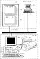
図1は、ユーザサポートをオンラインで行う場合のシステム構成例を示す説明図である。図の上半分にはユーザサポートを行うサポートセンタの構成を示し、下半分にはユーザが使用するクライアントシステムの構成を示した。サポートセンタは、ユーザサポート用サーバSVと、サポート要員とから構成される。デバイスのユーザへのユーザサポートは、いかなる者が提供しても構わないが、本実施例では、説明の便宜上、プリンタのメーカがサポートを提供するものとする。以下、デバイスの例としてプリンタ20を使用して説明する。
【0025】
クライアントシステムは、コンピュータ90にプリンタ20がパラレルケーブルにより接続された構成をなしている。本実施例では、パラレルケーブルを用いてプリンタ20がコンピュータ90にローカルに接続されている場合を例示したが、LAN(Local Area Network)を介して接続される構成であってもよい。ただし、いずれの場合でも、コンピュータ90とプリンタ20との間で双方向通信が可能であることが望ましい。
【0026】
コンピュータ90には、所定のオペレーティングシステム11上で起動するいくつかのプログラムがインストールされている。ここでは、代表的なプログラムとして、Webページの閲覧に供されるブラウザ10と、プリンタ20を駆動する機能を奏するプリンタドライバ12と、プリンタ20で印刷する文書および画像データを生成するアプリケーションプログラム14とを示した。印刷を行う時には、アプリケーションプログラム14から、印刷コマンドとともに印刷すべきファイルがプリンタドライバ12に受け渡される。プリンタドライバ12は、このファイルに対し、レンダリングその他の処理を行って、プリンタ20に供給する印刷データを生成する。プリンタ20は、パラレルケーブルを介してこの印刷データを受け取り、印刷を実行する。なお、プリンタ20には、その動作を制御するファームウェア22と、少なくともプリンタの動作状態を保持するデータベースであるMIB(Management Information Base)46とを備えている。コンピュータ90は、このMIB46にアクセスすることにより、プリンタ20の動作環境などに関する情報を得ることができる。
【0027】
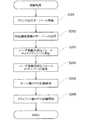
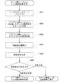
図2は、オンラインサポート用ユーザ登録処理の手順を示すフローチャートである。ステップS101では、コンピュータ90とプリンタ20が接続される。この接続が、オンラインサポート用ユーザ登録処理開始のトリガーとなる。ただし、この接続の時に、プリンタドライバ12がコンピュータ90にインストールされていない場合も想定される。このときは、プリンタドライバ12のインストールがオンラインサポート用ユーザ登録処理開始のトリガーとなる。ステップS102では、プリンタIDがコンピュータ90に登録される。この登録が完了すると、ステップS103に進み、ユーザに対して登録の希望の有無を問い合わせるダイアログボックス(図示せず)が表示される。
【0028】
ユーザが登録を希望しない旨の応答をした場合はステップS104に進み、ユーザ登録用アイコンを、たとえば、デスクトップ上に生成した上で、ユーザ登録処理を終了する。ユーザ登録用アイコンを作るのは、ユーザがいつでもユーザ登録できるようにするためである。一方、ユーザが、登録を希望する旨の応答をした場合は、図3に示すダイアログボックスが表示される。
【0029】
図3は、ユーザに対して情報提供の可否の問い合わせを行うダイアログボックスを例示する説明図である。このダイアログボックスは、ユーザに対して、ユーザサポートのための情報提供を許可する否かを確認するものである。情報提供の可否の確認をするのは、本実施例におけるユーザサポートでは、クライアントシステム内部の情報の提供が必要であり、この情報は個人情報に属する可能性があるからである。ユーザが情報提供を拒否した場合は、その旨がユーザ登録情報として記録され、従来のサポート方法により対応することになる。
【0030】
ステップS105では、ユーザサポート用アイコンが生成される。このユーザサポート用アイコンをクリックすることにより、登録ユーザは、本発明の1実施例であるオンラインによるユーザサポートを受けることができる。また、ユーザ登録処理が通信エラーその他の事情により中断したときには、このユーザサポート用アイコンをクリックすることにより、ユーザ登録処理を再開できる。
【0031】
ステップS106では、コンピュータ90がユーザサポート用サーバSVに接続される。この接続は、プリンタドライバ12が、コンピュータ90に登録されたプリンタIDを使用して自動的に行うものである。接続が完了すると、ステップS107に進みユーザサポート用サーバSVへのユーザ登録処理が開始される。
【0032】
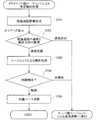
図4は、ユーザサポート用サーバSVへの登録処理の手順を示すフローチャートである。ステップS201では、ユーザサポート用サーバSVにユーザのプリンタIDを登録する。プリンタIDを登録することにより、これを基準として顧客データベースを生成することができ、顧客管理が容易となる。ステップS202では、コンピュータ90がユーザサポート用サーバSVにクライアント側の印刷環境情報を送信する。この印刷環境情報は、クライアントシステムの形態情報のうち、印刷作業の実行に関係する可能性のある情報である。この情報をユーザサポート側が把握することにより、ユーザサポートが容易になる。
【0033】
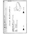
図5は、ユーザサポートのためにクライアント側からユーザサポート用サーバSVに送信する情報を例示する表である。図示するように、このサーバに送信する情報には、印刷環境情報の他、デバイス異常診断用情報として使用できる印刷ログ情報、操作ログ情報、そして処理データを含めることもできる。これらのデータの詳細については後述する。また、印刷環境情報は、印刷環境に変化がある度に、その変化を記録しておくのが好ましい。印刷環境の変化が原因となってサポートが必要となる場合も多いため、印刷環境の変化もサポートの実施に有益な情報となるからである。印刷環境情報の取得は、たとえば、コンピュータ90のオペレーティングシステム11がWindowsの場合、レジストリデータの一部又は全部を読み込むことにより、可能である。また、プリンタ20に備えられたMIB46に印刷環境情報を記録するようにし、ユーザサポート用サーバSVにアップロードするようにしても良い。ユーザサポート用サーバSVが印刷環境情報の受信を完了すると、ステップS203に進む。
【0034】
ステップS203では、ユーザサポート用サーバSVは、コンピュータ90に、ユーザ登録用の送信フォーム120(図1)を送信する。このフォームは、先に受信した情報に応じてカスタマイズしても良い。たとえば、デバイス毎に送信フォーム120を変えても良い。ステップS204では、ユーザは、ユーザ登録用の送信フォーム120に所定の事項を入力し、ユーザサポート用サーバSVに送信する。これにより、プリンタIDとユーザを一致させることができる。すなわち、プリンタIDからユーザを特定することができるので、ユーザサポートがさらに容易になる。
【0035】
ステップS205では、ユーザサポート用サーバSVで、そのユーザのサポートに関するログの記録が開始される。このログを参照することにより、サポートを求めているユーザが過去にどのようなサポートを受けているかを知ることができる。これにより、ユーザサポート要員は、ユーザサポートをより円滑に進めることができる。
【0036】
ステップS206では、クライアントシステムのログの記録が開始される。このログには、図5に示すように、印刷ログ情報と操作ログ情報がある。印刷ログ情報は、サポートの対象となるプリンタ20の過去における印刷に関する情報、たとえば、どのような印刷環境で、いつ、どれだけの量の印刷が行われたかを表す情報である。操作ログ情報は、たとえば、エラー発生時またはサポート用アイコンのクリック前の、一定期間の操作内容の記録である。これらの情報は、ユーザサポート側で、ユーザがサポートを求める状況を再現するために使用する情報である。サポートの対象となる状況をサポート側で再現できれば、適切なユーザサポートを確実に行うことができるからである。
【0037】
これらの情報の記録は、コンピュータ90の記憶装置、プリンタ20のMIB46、またはその双方に行うことができる。しかし、これらの機器に故障が発生し得ることを考慮すると、双方に記録するのが好ましい。
【0038】
B.サポート要員を中心としたユーザサポート:
図6は、サポート要員によるユーザサポート処理の手順を示すフローチャートであり、図7は、希望するサポートの内容をユーザに問い合わせるダイアログボックスを例示する説明図である。ステップS301では、ユーザがユーザサポート用アイコンをクリックする。これにより、ユーザサポート処理が開始され、ステップS302に進む。ステップS302では、コンピュータ90が、インターネットを経由して、ユーザサポート用サーバSVに接続される。この接続が完了すると、ステップS303に進み、図7に示すダイアログボックスが表示される。このダイアログボックスでは、ユーザは、サポートの内容を、たとえば、「操作内容の問い合わせ」と「故障」とから選択することができる。この選択がなされると、ステップS304に進み、コンピュータ90は、その選択結果とともに、プリンタIDをユーザサポート用サーバSVに送信する。
【0039】
プリンタIDを取得したサポートセンタは、プリンタIDを使用してサポート対象のプリンタ20を特定する。さらに、サポートセンタ内のデータベースに照会して、ユーザサポート登録ユーザを特定することもできる。さらに、同時に受信した印刷環境情報を調査することにより、ユーザサポート要員は、サポートが求められているクライアントシステムのその時点での印刷環境を知ることができる。また、プリンタIDとユーザが特定されているので、サーバ側ログ情報を参照することにより、さらに、過去の印刷環境と比較することもできる。これにより、サポートを円滑に進めることができる。ユーザの特定が完了すると、後述するダイアログボックスが表示される。
【0040】
図8は、ユーザの連絡先を確認するダイアログボックスを例示する説明図である。このダイアログボックスは、サポートセンタ内のデータベースに登録されたユーザと一致するかどうかを確認するとともに、サポートの対象となるユーザの連絡先を確認するために表示するものである。この確認が終了すると、ステップS305に進み、ユーザサポート用サーバSVが、コンピュータ90にユーザサポート用の送信フォーム120を送信する。なお、ユーザに変更がある場合、図8のダイアログボックスで、「いいえ」を選択することにより、再度ユーザ登録をすることができる。
【0041】
図9は、ユーザの置かれている状況の説明を入力する送信フォームを例示する説明図である。ステップS306では、クライアントシステムが受信したユーザサポート用の送信フォーム120(図1、図9)に、ユーザが、所定の事項を入力し、ユーザサポート用サーバSVに返信する。このユーザサポート用の送信フォーム120には、ユーザの入力を容易にするように、入力サンプルを添付したり、選択式の表示により記載内容を絞り込むようにするのが好ましい。この返信の際には、印刷環境情報、印刷ログ情報、操作ログ情報も同時送信される。サポートセンタの受信の完了をクライアントシステムが確認すると、情報の取得が完了し、クライアントシステムとユーザサポート用サーバSVの接続が解除される。なお、この接続の解除の時に、サポートセンタから、追って連絡があることを示す表示(図示せず)を行うのが好ましい。
【0042】
ステップS307では、サポート要員によるクライアントシステムの状況分析が開始される。この状況の分析は、たとえば、異常に対するサポートの場合は、以下の手順で行うことができる。
(1)ユーザの技量の推定を行う。これは、サーバ側に記録された過去のサポートのログ情報から推定することができる。この技量を知ることで、簡単な異常か深刻な異常かをある程度推定することができる。
(2)印刷環境を特定する。ソフトウェアの干渉その他の印刷環境に基づく異常でないかどうかを、まず、チェックする。このチェックは、サポートセンタ内にデータベース化されたサポート情報を照会することにより行う。また、過去の印刷環境と比較することにより、現在の印刷環境との相違を特定し、異常診断の参考資料とすることもできる。さらに、印刷ログ情報を取得できれば、正常に行われた過去の印刷状況やプリンタ20の負荷を知ることができ、異常の原因の特定が容易になる。
(3)操作内容を特定する。操作ログ情報を取得できれば、エラーその他のサポートを求める状況が発生するまでの操作内容を特定することができる。操作内容まで特定できれば、クライアントシステムの環境をサポートセンタ側で再現することもでき、サポートがさらに容易になる。
【0043】
サポート要員による分析が終了すると、ステップS308に進み、ステップS304で確認された連絡先に、分析結果が電子メールとして送信される。なお、電子メールだけでなく、ファックスや電話で連絡するようにしても良い。電子メール等の内容は、定型化してデータベース化しておくのが好ましい。こうすれば、重複労力を軽減することができ、サポートの効率が向上する。
【0044】
以上のように、印刷環境情報その他のユーザサポートに必要な情報が、オンラインで客観的にユーザサポート要員に提供されるので、ユーザサポートが容易となる。また、ユーザにとってもクライアントシステムの状況を説明する負担が大きく軽減され、ユーザサポートの円滑な運用が可能となる。
【0045】
C.人工知能を中心としたユーザサポート:
図10は、分散型人工知能によるユーザサポートシステムの構成を示すブロック図である。これは、複数の人工知能(エキスパート)からなるエキスパートシステムである。このエキスパートシステムは、各エキスパートをエージェントとして定義し、各エージェントが単独で、または必要に応じて相談しながら、サポートを行うシステムである。このシステムを異常診断を例にとって、以下に説明する。
【0046】
この異常診断のためのエキスパートシステムは、クライアント側のエキスパートとして定義されるクライアント側エージェント200と、サーバ側のエキスパートとして定義されるサーバ側エージェント220とから構成される。クライアント側エージェント200は、ユーザ側の異常診断機能を有するエージェント(代理人)として機能し、サーバ側エージェント220は、サーバ側の異常診断機能を有するエージェント(代理人)として機能する。
【0047】
図11は、クライアント側エージェント200を中心とした印刷部100の構成を示すブロック図である。この印刷部100は、クライアント側エージェント200と、インタフェース専用回路50と、オペレーティングシステム11と、プリンタドライバ12と、アプリケーションプログラム14と、ファームウェア22と、機構部30とから構成される。このクライアント側エージェント200は、クライアント側監視・制御部201とクライアント側異常診断エキスパートシステム210とから構成される。
【0048】
クライアント側異常診断エキスパートシステム210は、異常診断のための推論を行うクライアント側推論エンジン211と、この推論の根拠となる知識から構成されるクライアント側知識ベース212と、推論過程をユーザに対して説明するための情報を生成するクライアント側推論過程説明部213とから構成される。クライアント側異常診断エキスパートシステム210の開発は、空の知識ベースと推論エンジンとからなる汎用のエキスパートシステム構築ツールを利用して、容易に行うことができる。すなわち、印刷部100の異常診断用の知識を知識ベースに蓄積することにより、印刷部100用の異常診断エキスパートシステムを構築することができる。汎用のエキスパートシステム構築ツールには、EMYCIN(商標)やESHELL(商標)を初めとして、多くのツールが開発され利用可能な状態にある。さらに、Macintosh、Windows、UNIX環境で作動するC言語ベースのものも普及しつつある。
【0049】
クライアント側エージェント200が備える異常診断エキスパートシステム210は、データが入力された知識ベースを備えるエキスパートシステムとして、プリンタ20とともにユーザに提供しても良く、汎用のエキスパートシステム構築ツールとして、ユーザに提供しても良い。後者の場合、知識ベースに入れるデータは、ユーザサポート用サーバSVからダウンロードする。なお、いずれの場合も知識ベース内のデータを更新できるようにするのが好ましい。
【0050】
クライアント側エージェントの監視・制御部201は、異常の検出と異常診断のための情報の収集を行うクライアント側エージェント200の中核部である。このクライアント側監視・制御部201は、クライアント側異常診断エキスパートシステム210を制御するとともに、インタフェース専用回路50を介して、オペレーティングシステム11と、アプリケーションプログラム14と、異常診断の対象となるモジュール(プリンタドライバ12と、ファームウェア22と、機構部30)をも制御する。これにより、印刷部100の異常診断のための情報収集とその異常の修復を行う。なお、異常診断の対象に、オペレーティングシステム11やアプリケーションプログラム14を加えても良い。
【0051】
図12は、サーバ側エージェント220を中心としたサポートシステムの構成を示すブロック図である。このサーバ側エージェント220は、監視・制御部221と異常診断エキスパートシステム230とから構成されている。このサーバ側監視・制御部221は、状況に応じてインターネットを介して、クライアント側エージェント200とネゴシエートすることができ、印刷部100を直接的に監視・制御することもできる。このサーバ側異常診断エキスパートシステム230は、クライアント側異常診断エキスパートシステム210と同様に、推論エンジン231と、知識ベース232とを備え、さらに、専門家であるサポート要員が知識ベース232を編集するためのルールエディタ234を備える。
【0052】
図13は、本発明の実施例における異常診断処理の手順を示すフローチャートである。ステップS401では、クライアント側エージェント200の監視・制御部201が印刷部100の異常を検出する。この異常検出が異常診断処理のトリガーとなる。なお、異常が検出されなくても、ユーザサポート用アイコンをクリックすれば、異常診断処理が開始される。この異常診断処理が開始されると、後述するダイアログボックスが表示される。
【0053】
図14は、クライアントシステムが診断中であることを示すダイアログボックスを例示する説明図である。このダイアログボックスは、クライアント側エージェント200、サーバ側エージェント220、またはその双方が、印刷部100の異常診断を行っていることを示すものである。この異常診断を中止したい場合は、「中止」をクリックすると異常診断が中止される。このダイアログボックスにより、ユーザは、印刷部100の状況を知ることができるとともに、この異常診断をいつでも中止することができる。
【0054】
ステップS402では、クライアント側エージェント200が印刷部100の異常診断を行う。この異常診断は、印刷部100の内部で行う診断である。この診断により、診断結果が取得できれば異常解決処理に進み、診断不能と判断されるとダイアログボックス(図示せず)が表示される。このダイアログボックスは、ユーザサポート用サーバSVへのインターネット経由の接続許可をユーザに求めるものである。このユーザサポート用サーバSVへの接続は、クライアント側エージェント200で行う印刷部100内部の異常診断から、サーバ側エージェント220によるリモート異常診断またはクライアント側エージェント200とサーバ側エージェント220の協調による異常診断に移行するために行うものである。この接続が完了すると、ステップS403に進む。
【0055】
ステップS403では、サーバ側エージェント220が関与する異常診断が行われる。この異常診断には、前述のように様々な態様があり、たとえば、クライアント側エージェント200に替わって、サーバ側エージェント220が直接的に印刷部100を診断する態様と、サーバ側エージェント220とクライアント側エージェント200とが協調して異常診断を行う態様とがある。さらに、この協調による異常診断には、サーバ側エージェント220とクライアント側エージェント200とが互いに通信を行う態様と、黒板と呼ばれる共有メモリを、たとえば、サーバ側に設ける態様とがある。一般に、協調による異常診断の方が、サーバ側エージェント220のみによる異常診断より深刻な事態に対応できるという利点があるが、インターネットの通信量が多くなるという欠点を有する。したがって、異常の状況に応じて、いずれかを選ぶのが好ましい。たとえば、最初の段階では、サーバ側エージェント220のみが診断を行い、診断結果が出ない場合や後述する推定確率が低い場合に、協調診断に移行するようにしても良い。
【0056】
以上の診断の結果、診断結果が取得されたときは異常解決処理に進み、診断不能と判断されたときはダイアログボックス(図示せず)が表示される。このダイアログボックスは、人工知能(エキスパートシステム)によっては、異常の診断ができなかったことをユーザに知らせるとともに、サポート要員による異常診断への移行の許可をユーザに求めるものである。サポート要員による異常診断への移行が許可されなかったときは、異常診断処理は終了し、その旨が表示される。一方、この許可が為された場合、図9に示すダイアログが表示され、これにユーザが入力してサポートセンタに送信すると、ステップS404に進む。
【0057】
ステップS404では、サポート要員による異常診断が行われる。この異常診断の際、サポート要員は、クライアント側エージェント200とサーバ側エージェント220が収集した情報とその診断結果を考慮して、図9に示すフォームにユーザが記載した状況を分析することができる。これにより、サポート要員による異常診断についてもその負担が軽減される。一方、ユーザも印刷部100の状況の説明を簡略化でき、負担が軽減される。サポート要員による異常診断によっても診断ができないときは、ダイアログボックス(図示せず)が表示される。このダイアログボックスは、プリンタ20の回収またはサービスマンの派遣を希望するかどうかをユーザに問い合わせるものである。ユーザがプリンタ20の回収等を希望しないときは異常診断処理を終了し、希望するときはステップS405に進む。
【0058】
ステップS405では、状況に応じてプリンタ20の回収またはサービスマンの派遣が行われる。この際、プリンタIDによりプリンタ20が特定されているので、回収されたプリンタ20の修理担当者に、異常診断に関する情報や記録されている修理履歴を提供することができる。これにより、修理の負担も軽減される。また、サービスマンの派遣に際しても、同様の情報をあらかじめ提供することができる。
【0059】
図15は、クライアント側エージェント200による異常診断処理の手順を示すフローチャートである。ステップS501では、クライアント側エージェント200がログ情報を取得する。このログ情報には、前述のように、印刷ログ情報と操作ログ情報とがある。ログ情報は、コンピュータ90の記憶装置とプリンタ20のMIB46の少なくとも一方に記録されており、いずれかから読み出す。
【0060】
印刷ログ情報は、サポートの対象となるプリンタ20の過去における印刷に関する情報、たとえば、どのような印刷環境で、いつ、どれだけの量の印刷が行われたかを表す情報である。過去にどのような印刷作業が実行されたかで、たとえば、プリンタ20の負荷の大きさを知ることができ、異常の特定の参考とすることができる。たとえば、プリンタ20の特定の部品の寿命が近づいているかどうかの判断の資料となる。また、異常発生の前に極めて長い間プリンタ20が使用されていないときは、インクの揮発による濃縮化やノズルの詰まりが疑われる。
【0061】
また、過去に多くの印刷作業を行っているか否かで、ユーザの印刷作業に関する技量を知ることもできる。これにより、たとえば、ユーザの操作方法に問題があるのを、「故障」としてサポートを求めてきていないかどうかの判断の一資料ともなる。さらに、ユーザの使用に関する問題、たとえば、ユーザが使用方法で困っているようなときにサポートを求めてきた場合にも、ユーザの技量を推定することができ、サポートが容易になる。
【0062】
操作ログ情報は、たとえば、エラー発生時またはサポート用アイコンのクリック時の前の、一定期間の操作内容の記録である。この記録は、コンピュータ90やプリンタ20に対してなされた操作内容の特定に使用できる。この情報は、クライアントシステム内の所定のメッセージ信号やイベント信号に関する情報である。また、この操作ログ情報には、エラーコードやエラーメッセージを含めても良い。これにより、異常の特定がさらに容易になるからである。
【0063】
ステップS502では、印刷環境情報の取得を行う。印刷環境情報には、図5に示すように、たとえば、オペレーティングシステム11、プリンタドライバ12、およびファームウェア22の情報(バージョン情報と設定情報)、インクカートリッジID、インク残量、インク開封日、コンピュータ90搭載のメモリの量、CPUといった印刷部100による印刷の実行に関係のある環境情報が含まれる。この印刷環境情報には、過去における印刷環境の変化の径時的な記録を含めるのが好ましい。正常に印刷しているときの印刷環境を知ることが、異常の診断に特に有益だからである。
【0064】
ステップS503では、異常部位の特定を行う。異常部位の特定とは、たとえば、プリンタドライバ12、コンピュータ90とプリンタ20の接続部、ファームウェア22、機構部30のいずれに異常があるかを特定するための処理である。これは、異常診断の推定精度を上げるために行う処理である。
【0065】
図16は、本発明の実施例における異常部位特定処理の手順を示すフローチャートである。ステップS601では、たとえば、クライアント側エージェント200の監視・制御部201が100×100のRGBテストデータをプリンタドライバ12に入力する。ステップS602では、プリンタドライバ12による処理データと正常時におけるプリンタドライバ12の処理データとを比較する。正常時におけるプリンタドライバ12の処理データは、たとえば、プリンタドライバ12インストール時に、あらかじめクライアント側エージェント200が取得しておいたものである。
【0066】
この両処理データが一致する場合、プリンタドライバ12は正常に処理していることになる。一方、処理データに不一致が見られた場合、プリンタドライバ12が正常に処理していないことが明らかになる。すなわち、プリンタドライバ12の作動に異常があることが分かる。
【0067】
ステップS603では、ファームウェア22の入力データをチェックする。入力データをチェックするのは、コンピュータ90とプリンタ20との接続をチェックするためである。このチェックは、たとえば、プリンタドライバ12の出力データをプリンタ20に送信し、プリンタ20でバッファして、さらに、コンピュータ90に送り返し、そのデータとプリンタドライバ12の出力データを比較する方法が考えられる。これにより、コンピュータ90とプリンタ20との接続に問題があるかどうかが明らかになる。また、コンピュータ90とプリンタ20との間で行われる制御データの確認も同様にして行うのが好ましい。たとえば、制御信号にノイズが乗って問題が生じている場合に、その特定が可能となるからである。
【0068】
ステップS604では、ファームウェア22の作動をチェックする。このチェックは、プリンタドライバ12のチェックと同様の方法により行うことができる。ステップS605では、機構部30のチェックを行う。このチェックは、機構部の中に備えられたセンサを使用して、たとえば、紙づまりの有無をチェックする。なお、異常部位特定処理の対象に、アプリケーションプログラム14やオペレーティングシステム11を含めても良い。異常部位特定処理が終了すると、ステップ504に進む。
【0069】
ステップS504では、印刷部100の状態推定を行う。この状態推定は、ステップS501〜503で取得した情報に基づいて、たとえば、
(1)プリンタドライバ12が他のソフトウェアと干渉している。
(2)ファームウェア22が破損している。
(3)コンピュータ90とプリンタ20の接続に問題がある。
といった観点からの印刷部100の状態の推定である。
【0070】
ステップS505では、修復計画を生成する。この修復計画は、印刷部100の推定された状態から正常な状態へ変化させるための工程を規定するものである。たとえば、プリンタドライバ12が他の特定のソフトウェアと干渉している場合、そのソフトウェアを削除するのが最も簡単な修復方法である。ファームウェア22が破損している場合、ファームウェア22の再インストールが可能であればそれが最も簡単な修復方法である。ファームウェア22の再インストールは、ファームウェア22が、EEPROMのような書き換え可能なメモリに格納されていれば可能である。また、コンピュータ90とプリンタ20の接続に問題がある場合、接続コネクタにぐらつきはないか、接続方法に問題がないかをユーザに確認するように示唆することが考えられる。
【0071】
修復計画を生成において、複数の診断結果と複数の修復方法が得られた場合、クライアント側エージェント200は、ユーザにとって負担の小さなものから順に提案する。たとえば、プリンタドライバ12が他のソフトウェアと干渉しているとの推定の確率が40%で、ファームウェア22が破損しているとの推定の確率が30%の場合、推定確率だけを考慮すると他のソフトウェアの削除が第1の修復方法案となる。しかし、この場合、そのソフトウェアをユーザが使用することができなくなる。一方、ファームウェア22の再インストールは、ユーザにとって負担がないに等しい。したがって、この場合は、ファームウェア22の再インストールが第1の修復計画となる。
【0072】
また、第1に優先となる修復計画は、エキスパートシステムによる自動修復が可能なソフト的なものとし、第2に優先される修復計画は、ユーザがハード的に修復できるもの、たとえば、コンピュータ90とプリンタ20との接続方法の変更とし、最後はサービスマンの派遣や回収とする。こうすれば、最小の負担で修復が可能となる確率が高くなる。
【0073】
ステップS506では、診断結果の決定可否を判断する。この判断は、推定確率と修復負担とから、有効な解決方法が見いだせたか否かにより、総合的に判断する。たとえば、推定確率が十分大きく修復負担が十分小さい場合には、ユーザに提示する診断結果として決定する。また、推定確率が多少小さくても修復負担が極めて小さい場合には、それを診断結果として決定する。一方、推定確率が多少大きくても、ユーザ負担が極めて大きい大きい場合、たとえば、回収が必要と診断された場合は決定しない。診断結果が決定されたときは、クライアント側エージェント200による異常解決処理に進み、診断結果が決定されないときは、サーバ側エージェント220の異常診断処理に進む。
【0074】
図17は、本発明の実施例におけるクライアント側エージェント200による異常解決処理の手順を示すフローチャートである。ステップS701では、推論過程説明部213が推論過程の情報を生成する。この情報は、異常診断における推論過程をユーザに説明するためのデータ、たとえば、テキストデータであり、ユーザが、エキスパートシステムによる診断結果と修復計画の提案の受諾または拒否の判断に使用するものである。この情報の生成が完了すると、ステップS702に進み、解決方法の提案と推定過程の説明が行われる。
【0075】
図18は、クライアント側エージェント200による診断結果を示すダイアログボックスを例示する説明図である。このダイアログボックスは、異常についての診断結果をユーザに知らせるとともに、その修復方法をユーザに提案する。また、「推定過程の確認」をクリックすると、診断結果に至るまでの推定の過程をユーザに説明する画面が表示される。この画面については後述する。
【0076】
ユーザは、診断結果を見て、また、必要であればその推定過程も見て、修復方法が妥当か否かを判断する。ユーザが妥当と判断して、「はい」をクリックするとステップS703に進み、クライアント側エージェント200が印刷部100の修復を行う。一方、ユーザが妥当でないと判断して、「いいえ」をクリックすると、別の修復計画を提案することになる。エージェントによる修復作業が完了すると、ステップS704に進む。一方、クライアント側エージェント200によるすべての提案を受諾できない場合は、サーバ側エージェント220が関与する異常診断処理に進む。
【0077】
ステップS702とS703を具体例を使用して説明する。この例では、あるソフトウェアとプリンタドライバ12が干渉しているとの診断結果が得られた場合である。この場合、クライアント側エージェント200は、図18に示すようなダイアログボックスを表示して、修復方法の提案受諾を求める。ユーザが受諾した場合、たとえば、試しにインストールしたフリーウェアのように、そのソフトウェアが重要なものでないときは、「はい」をクリックすれば、そのソフトウェアを、クライアント側エージェント200の監視・制御部201が削除する。
【0078】
この際、ユーザは、「推定過程の確認」をクリックすることにより、推定過程を確認することもできる。この推定過程は、ユーザがクライアント側エージェント200が提案する修復計画を受諾するかどうかの参考となるものである。一方、そのソフトウェアの削除を望まない場合は、ユーザは、「いいえ」をクリックする。そうすると第2の修復計画が提示される。第2の修復計画がない場合は、ユーザサポート用サーバSVに接続して診断をサーバ側エージェント220も含めて再度診断を行う。あるいは、複数の診断結果と修復計画を同時に表示して、ユーザに選択させるようにしても良い。
【0079】
図19は、クライアント側エージェント200による推定過程を示すダイアログボックスを例示する説明図である。このダイアログボックスは、修復提案の受諾を行うかどうかについてのユーザの判断を、より的確かつ容易にするものである。また、図19に示すように、このダイアログボックスで、クライアント側エージェント200が感知できない症状をユーザに確認させるのが好ましい。これにより、ユーザはより的確な判断ができるからである。たとえば、症状が印刷結果に生ずる問題である。
【0080】
ステップS704では、ユーザに対して、問題が解決したかどうかダイアログボックス(図示せず)で確認する。この結果、問題が解決したときは、ステップS705に進み、問題が解決しないときは、サーバ側エージェント220による異常診断処理に進む。ステップS705では、クライアント側エージェント200の知識ベースの更新を行う。この更新は、第1に推定確率を見直すためのものである。すなわち、異常が解決したときは、その診断に使用した知識の推定確率を上げる。第2に、特定の異常を解決した旨を記録し、次回に同じ状態になったときにユーザに知らせるためのものである。
【0081】
図20は、サーバ側エージェント220による異常診断処理の手順を示すフローチャートである。ステップS801では、コンピュータ90がユーザサポート用サーバSVにアクセスする。このアクセスは、クライアント側エージェント200が、ユーザの許諾を得て自動で行う。このとき、ユーザの許諾は、ダイアログボックス(図示せず)を使って行う。
【0082】
ステップS802では、クライアント側エージェント200が、その収集した情報と診断結果をユーザサポート用サーバSVに送信する。これにより、サーバ側エージェント220がクライアント側エージェント200が取得した情報と診断結果を得ることができる。サーバ側エージェント220は、この情報に基づいて診断を行う。この診断を行う方法には、サーバ側エージェント220がクライアント側エージェント200に替わって単独で診断する方法と、サーバ側エージェント220がクライアント側エージェント200と協調して、診断を行う方法がある。後者は、一般に、マルチエージェントシステムと呼ばれる。
【0083】
また、マルチエージェントシステムには、エージェント同士が通信して情報を共有する契約ネットの方式と、二つのエージェントがメモリを共有する黒板方式とがある。
【0084】
ステップS803では、クライアント側エージェント200を介したさらなる情報収集を行う。この情報収集は、サーバ側エージェント220が、診断のためにさらに情報収集が必要と判断した場合に行われる。情報収集の方法は、サーバ側エージェント220がクライアント側エージェント200に情報を要求するか、サーバ側エージェント220がクライアント側エージェント200をスレーブエージェントして、直接制御することにより行う。
【0085】
ステップS804では、サーバ側エージェント220の異常診断エキスパートシステム230が、その収集した情報に基づいて、その知識ベース232を使用して診断する。この代わりに、サーバ側エージェント220が、クライアント側エージェント200と協調して、印刷部100の状態推定を行うようにしてもよい。ステップS805では、この推定された状態に基づいて、修復計画を生成する。ステップS806では、診断結果をコンピュータ90に表示し、サーバ側エージェント220による異常解決処理に進む。診断不能と判断された場合は、サポート要員による異常診断に進む。
【0086】
図21は、サーバ側エージェント220による異常解決処理の手順を示すフローチャートである。サーバ側エージェント220は、最新の知識ベース232を使用して、診断と修復計画を行うことができる。たとえば、知識ベース232に、最新のバージョンのプリンタドライバ12が、前述したソフトウェアとの干渉を起こさない旨のデータがあった場合、プリンタドライバ12の最新のバージョンへの更新で異常を解決できる旨の診断を決定できる。
【0087】
サーバ側エージェント220による異常解決処理の手順は、クライアント側エージェント200による異常解決処理の手順とほぼ同じである。ただし、サーバ側エージェント220による提案が拒否された場合の後の処理と、問題が解決したの後の処理(ステップS905)が異なる。すなわち、このような提案が拒否された場合、サポート要員によるサポートに移行する。また、問題が解決したの後は、サーバ側の知識ベース232が更新されるが、この更新は、解決までの過程を確認したサポート要員がルールエディタ234(図12)を用いて行うのが好ましい。さらに、更新された知識ベースの一部を、デバイスに応じて、ユーザにダウンロードできるようにすることもできる。このときには、デバイスIDを用いて、必要な知識ベースを特定することもできる。
【0088】
図22は、サーバ側エージェント220による診断結果を示すダイアログボックスを例示する説明図である。このダイアログボックスは、新しいプリンタドライバ12への更新の可否をユーザに問い合わせるものである。ユーザが「はい」をクリックすると、サーバ側エージェント220が、ユーザサポート用サーバSV内のプリンタドライバ12のデータを使用して、自動的にコンピュータ90のプリンタドライバ12を更新する。ユーザが「いいえ」をクリックすると、第2の修復計画が提示されるか、サポート要員による診断に移行する。このときも、修復計画が複数あるときは、最初から複数提示するようにしても良い。
【0089】
サポート要員による診断への移行に際しては、図7〜図9が表示され、本発明の第1の実施例(サポート要員を中心としたユーザサポート)の手順で処理が行われる。ただし、前述のように、サポート要員は、クライアント側エージェント200とサーバ側エージェント220により収集した情報と診断結果を使用して診断を行うことができる。
【0090】
サポート要員による診断により異常が解決した場合、診断結果と異常の解決方法に関する情報をデータベース化し、他のサポート要員が使用できるようにするとともに、知識ベースを更新することもできる。具体的には、ルールエディタ234(図12)を使用して、サーバ側知識ベース232を更新し、さらに、クライアント側知識ベース212も更新可能とするのが好ましい。こうすれば、同様のサポートの要請に対して、人工知能で対応することでき、重複労力が軽減されることになる。
【0091】
以上に説明した人工知能を中心としたサポート方法は、ユーザのサポート負担を飛躍的に軽減するとともに、サポート要員の重複労力を軽減することができる。
【0092】
D.サポート例:
以下では、上述した実施例において、デバイスの異常がどのように解決されるかを具体例に則して説明する。第1の事例は、Macintosh環境で特定のアプリケーションプログラム14(図1)を使用して印刷をしようとするとコンピュータ90がフリーズする場合である。このときの症状は、特定のアプリケーションプログラム14が停止し、所定のエラーメッセージがディスプレイ上に表示されて正常に印刷できないというものである。この異常は、以下の条件で発生する。
(1)オペレーティングシステム11がMacintoshである。
(2)特定のアプリケーションプログラム14でのみ発生する。
(3)プリンタドライバ12の設定が「ページを縮小する」に設定されている。
この事例に対する最も有効な対応策は、プリンタドライバ12の設定を「ページを縮小する」から、「プリント領域外の部分はプリントしない」または「プリント領域外の部分を別ページにプリントする」に変更することである。
【0093】
この事例において、サポート要員を中心としたユーザサポートは、以下のように行われる。サポート要員は、オンラインで印刷環境情報と操作ログ情報を取得しており、この情報には、
(1)オペレーティングシステム11がMacintoshであること。
(2)特定のアプリケーションプログラム14の操作においてエラーが発生していること。
(3)所定のエラーメッセージが出力されていること。
(4)プリンタドライバ12の設定が「ページを縮小する」に設定されている。
が含まれている。したがって、異常の原因を容易に特定することが可能である。この特定は、サポートセンタにあるサポートのための共有データベースと照合することにより、客観的に行うのが好ましい。
【0094】
異常を特定したと判断したサポート要員は、ユーザに対して、電子メールや電話で症状を確認した上で、プリンタドライバ12の設定の変更その他の有効な異常回避方法を提案することができる。
【0095】
このように、ユーザが異常の状況を説明しなくても、サポート要員は、客観的かつ正確な情報を容易に取得することができる。これにより、ユーザとサポート要員の双方の負担が大きく軽減され、円滑なサポートができることになる。
【0096】
一方、人工知能を中心としたユーザサポートは、以下のように行われる。クライアント側エージェント200(図11)は、そのクライアント側監視・制御部201を通じて、コンピュータ90の内部で印刷環境情報と操作ログ情報を取得しており、この情報には、
(1)オペレーティングシステム11がMacintoshであること。
(2)特定のアプリケーションプログラム14の操作においてエラーが発生していること。
(3)所定のエラーメッセージが出力されていること。
(4)プリンタドライバ12の設定が「ページを縮小する」に設定されている。
といった情報が含まれている。
【0097】
印刷環境情報と操作ログ情報から、不具合が発生する条件を満たし、その確率が80%であることが分かる。クライアント側エージェント200の異常診断エキスパートシステムが有する知識ベース212には、この異常が発生する条件とその条件が満たされた場合の異常の発生確率(80%とする)、そして異常が発生したときの症状が入力されているからである。
【0098】
次に、異常部位特定処理(図16)で、プリンタドライバ12等自体の異常の有無を確認する。プリンタドライバ12等自体に異常がなければ、アプリケーションプログラム14自体またはアプリケーションプログラム14とプリンタドライバ12の相性に問題があることが50%の確率で推定できる。
【0099】
以上の分析より、印刷部100の状態として90%の推定確率で上記の異常があることが自動的に推定できる。この推定に基づいて、正常な印刷部100に修復するための手順を策定する。この修復計画の策定が完了すると、診断結果をユーザに知らせて修復方法を提案するダイアログボックス(図23)が表示される。
【0100】
図23は、診断結果を示すダイアログボックスを例示する説明図である。このダイアログを見ることにより、ユーザは、異常の原因とその修復方法の概要を知ることができる。ユーザは、この情報に基づいて、クライアント側エージェント200による修復を許可するか否かを判断することがきる。ユーザは、この提示された情報のみでクライアント側エージェント200に修復を任せて良いと判断した場合、「はい」をクリックする。推定過程を確認したい場合は、「推定状態の確認」をクリックする。一方、この診断に承服できないときは、「いいえ」をクリックする。
【0101】
図24は、診断結果に至るまでの推定過程を示すダイアログボックスを例示する説明図である。このダイアログボックスは、クライアント側エージェント200による診断と修復方法の適否を、ユーザが判断するためのものである。このダイアログボックスは、複数ページに渡るものとしても良く。また、判断の要素となる各判断基準の推定確率を表示するものでも良い。さらに、診断された異常からユーザが関知できる症状を表示することにより、ユーザによる判断を容易にするのが好ましい。
【0102】
クライアント側エージェント200による診断の結果、複数の異常が推定され、各々の確率の差が小さい場合、この画面でユーザと対話する事により、状態推定を進めるようにしても良い。たとえば、推定された各状態に伴う症状をユーザに説明し、該当するか否かをユーザが選択的に回答させることで、推定を進めることができる。これにより、さらに、精度の高い推定が可能となる。
【0103】
図25は、複数の修復方法を示すダイアログボックスを例示する説明図である。この事例においては、修復方法に選択の余地があるので、複数の修復方法が提案されている。ユーザは、この中から、自分が望む修復方法を選択し、クリックする。こうすると、クライアント側エージェント200がその監視・制御部201を用いて、自動的に修復する。
【0104】
以上のように、クライアント側エージェント200とサーバ側エージェント220が自動的に診断・修復することにより、異常発生時のユーザ側の負担は大きく軽減される。また、ユーザサポートを一部自動化することにより、ユーザサポートの重複労力が軽減され、その円滑な運用が可能となる。
【0105】
E.新技術の先行提供:
図26は、本発明の実施例における新技術の先行提供の手順を示すフローチャートであり、図27は、希望するサポートの内容をユーザに問い合わせるダイアログボックスを例示する説明図である。この処理は、たとえば、プリンタドライバ12のベータ版の配布のように、品質の保証がなされていないソフトウェアの先行版を特定のユーザにのみ配布するための処理である。この処理は、以下の手順で行われる。
【0106】
ステップS1001では、ユーザがユーザサポートアイコンをクリックする。そうすると、希望するサポートの内容をユーザに問い合わせるダイアログボックスがコンピュータ90のディスプレイに表示される。ユーザが「新技術を試す」をクリックすると、ステップS1002に進む。
【0107】
ステップS1002では、コンピュータ90が、インターネットを介してユーザサポート用サーバSVに接続される。ステップS1003では、オーソライゼーションがなされる。このオーソライゼーションは、クライアントシステムがユーザ登録において取得したユーザID、プリンタID、およびパスワードを送信し、ユーザサポート用サーバがそれを確認することにより行われる。
【0108】
ステップS1004では、ユーザがソフトウェアを選択する。この選択は、たとえば、ダイアログボックス(図示せず)にリストアップされるソフトウェアから、ユーザが試してみたいものをクリックすることにより行われる。ステップS1005では、選択されたソフトウェアを、プリンタ20に接続されたコンピュータ90にインストールする。このインストールは、ユーザサポート用サーバSVがコンピュータ90に対して直接行う。また、インストールするソフトウェアは、たとえば、そのプリンタでのみ動作するように、ソースコードを修正した上でコンパイルしたものである。こうすれば、そのソフトウェアは、インストールされたコンピュータ90上でしか作動しないことになる。
【0109】
インストールが正常に完了すると、その旨がユーザサポートサーバに送信され、そのユーザのユーザIDとプリンタIDが登録される。この際、印刷環境情報をユーザサポート用サーバSVに自動的にアップロードするのが好ましい。
【0110】
以上の手順により、新技術の提供を登録ユーザに限定することができ、また、品質の保証がなされていないソフトウェアが再配布により拡散するという弊害を防止することができる。
【0111】
F.変形例:
なお、この発明は上記の実施例や実施形態に限られるものではなく、その要旨を逸脱しない範囲において種々の態様において実施することが可能であり、たとえば次のような変形も可能である。
【0112】
本発明の機能の一部または全部がソフトウェアで実現される場合には、そのソフトウェア(コンピュータプログラム)は、コンピュータ読み取り可能な記録媒体に格納された形で提供することができる。この発明において、「コンピュータ読み取り可能な記録媒体」とは、フレキシブルディスクやCD−ROMのような携帯型の記録媒体に限らず、各種のRAMやROM等のコンピュータ内の内部記憶装置や、ハードディスク等のコンピュータに固定されている外部記憶装置も含んでいる。
【図面の簡単な説明】
【図1】ユーザサポートをオンラインで行う場合のシステム構成例を示す説明図。
【図2】オンラインサポート用ユーザ登録処理の手順を示すフローチャート。
【図3】ユーザに対して情報提供の可否の問い合わせを行うダイアログボックスを例示する説明図。
【図4】ユーザサポート用サーバへの登録処理の手順を示すフローチャート。
【図5】ユーザサポートのためにクライアント側からユーザサポート用サーバに送信する情報を例示する表。
【図6】サポート要員によるユーザサポート処理の手順を示すフローチャート。
【図7】希望するサポートの内容をユーザに問い合わせるダイアログボックスを例示する説明図。
【図8】ユーザの連絡先を確認するダイアログボックスを例示する説明図。
【図9】ユーザの置かれている状況の説明を入力する送信フォームを例示する説明図。
【図10】分散型人工知能によるユーザサポートシステムの構成を示すブロック図。
【図11】クライアント側エージェントを中心とした印刷部の構成を示すブロック図。
【図12】サーバ側エージェント220を中心としたサポートシステムの構成を示すブロック図。
【図13】本発明の実施例における異常診断処理の手順を示すフローチャート。
【図14】クライアントシステムが診断中であることを示すダイアログボックスを例示する説明図。
【図15】クライアント側エージェントによる異常診断処理の手順を示すフローチャート。
【図16】本発明の実施例における異常部位特定処理の手順を示すフローチャート。
【図17】クライアント側エージェントによる異常解決処理の手順を示すフローチャート。
【図18】クライアント側エージェント200による診断結果を示すダイアログボックスを例示する説明図。
【図19】クライアント側エージェントによる推定過程を示すダイアログボックスを例示する説明図。
【図20】サーバ側エージェント220による異常診断処理の手順を示すフローチャート。
【図21】サーバ側エージェント220による異常解決処理の手順を示すフローチャート。
【図22】サーバ側エージェント220による診断結果を示すダイアログボックスを例示する説明図。
【図23】診断結果を示すダイアログボックスを例示する説明図。
【図24】診断結果に至るまでの推定過程を示すダイアログボックスを例示する説明図。
【図25】複数の修復方法を示すダイアログボックスを例示する説明図。
【図26】本発明の実施例における新技術先行提供の手順を示すフローチャート。
【図27】希望するサポートの内容をユーザに問い合わせるダイアログボックスを例示する説明図。
【符号の説明】
10…ブラウザ
11…オペレーティングシステム
12…プリンタドライバ
14…アプリケーションプログラム
20…プリンタ
22…ファームウェア
30…機構部
46…MIB
50…インタフェース専用回路
90…コンピュータ
100…印刷部
120…送信フォーム
200…クライアント側エージェント
201…クライアント側監視・制御部
210…クライアント側異常診断エキスパートシステム
211…クライアント側推論エンジン
212…クライアント側知識ベース
213…クライアント側推論過程説明部
220…サーバ側エージェント
221…サーバ側エージェント監視・制御部
230…サーバ側異常診断エキスパートシステム
231…サーバ側推論エンジン
232…サーバ側知識ベース
233…サーバ側側推論過程説明部
234…ルールエディタ
SV…ユーザサポート用サーバ[0001]
BACKGROUND OF THE INVENTION
The present invention relates to a technology for supporting online use of a device.
[0002]
[Prior art]
For various devices such as printers and scanners, a method of providing online support to users via the Internet is becoming widespread. An example of such support is a support method using e-mail. In this support method, when an abnormality occurs in the device, the user transmits the content of the abnormality by e-mail to a support department provided by the device manufacturer. The support department analyzes the cause of the abnormality from the information in the e-mail and presents a solution to the user.
[0003]
In addition, online support includes a support method for providing support information for solving problems related to device use and device anomalies, so-called online help, on a Web page on the Internet. In general, on a Web page provided by a device manufacturer, solutions are provided for typical problems and abnormalities and abnormalities that can be solved by the user.
[0004]
[Problems to be solved by the invention]
However, since it is difficult for a general user to fully explain the operation status of the device and its abnormality, it has been difficult to provide smooth support depending on an e-mail or a telephone. Further, since it is difficult for general users to understand the operation status of the device and its abnormality, it is still difficult to solve problems by using so-called online help.
[0005]
Further, in the conventional support method using e-mail or telephone, it is necessary to individually deal with the cause of the problem, and a duplicate burden is generated for support. As a result, support for serious abnormalities that are difficult to resolve has been hindered.
[0006]
The present invention has been made to solve the above-described problems in the prior art, and provides a technique for reducing the burden on both the user side and the support side when supporting device operation online. With the goal.
[0007]
[Means for solving the problems and their functions and effects]
In order to solve at least some of the above-mentioned problems, the present invention supports the use of a device online. In this case, first, a client equipped with the device connects to a user support server that supports the use of the device online, and then the client can specify device information that can specify the type of the device; Usage environment information indicating the usage environment of the device is transmitted to the server for user support. Finally, device support information for supporting the use of the device is generated using the information transmitted to the user support server, and the device support information is transmitted to the client.
[0008]
In the present invention, device information that can specify the device type;thisSince the usage environment information representing the usage environment of the device is transmitted to the user support server, the user of the device is freed from the burden of explaining the information to the user support side. On the other hand, the user support side can easily acquire information necessary for user support.BecauseSmooth user support is possible.The generation and transmission of device support information may be performed by support personnel, or may be automatically performed by a user support server as will be described later.
[0009]
Such support can be limited to a user who has previously acquired a user ID and a password for receiving permission to access the user support server of the client.
[0010]
In this way, the user to be supported and the device can be matched, information about the user can be accumulated, and smooth user support is possible. It is also possible to limit support to a specific user.
[0011]
In the above method,
When the client transmits device information that can identify the type of the device and usage environment information that indicates the usage environment of the device to the user support server, a client-side agent that the client has includes Device abnormality diagnosis information used for diagnosing an abnormality occurring in the device may be generated and transmitted to the user support server.
[0012]
In this way, it is possible to diagnose an abnormality with high accuracy and further facilitate user support.
[0013]
Prior to the connection of the client to the user support server, the client-side agent uses the use environment information indicating the use environment of the device to obtain device support information for supporting the use of the device. You may make it produce | generate.
[0014]
In this way, the burden on the user support side is reduced, and the user support information may be obtained without the user connecting to the communication line, so that the device abnormality can be solved more easily.
[0015]
In the above method,
The user support side agent possessed by the user support server uses the information transmitted to the user support server to generate device abnormality solution information used for solving an abnormality that has occurred in the device possessed by the client. Anyway.
[0016]
Accordingly, it is possible to solve an abnormality that cannot be solved on the client side by the information stored in the user support server.
[0017]
Furthermore, it is preferable that the user support server side agent resolves an abnormality that has occurred in the device of the client using the device abnormality solution information.
[0018]
By doing so, the abnormality occurring in the device is automatically resolved, so that the burden on the user is further reduced.
[0019]
Note that user support can be performed offline. In this way, the problem can be solved without connecting to the Internet.
[0020]
In another aspect of the present invention, information is provided online from a user support server that supports the use of the device online in response to a request from a client equipped with the device. In this case, first, the client connects to the user support server, and then the client transmits device information that can specify the device type to the user support server. Finally, the user In response to the information transmitted to the user support server, the support server transmits information used to use the device included in the client to the client.
[0021]
In this aspect, since device information that can specify the device type is transmitted to the user support server, information can be provided as information that can be used only by the device. As a result, for example, software under development whose quality is not guaranteed can be distributed only to a specific person.
[0022]
The present invention can be realized in various modes. For example, an information provision control method and an information provision control device, a computer program for realizing the function of the method or device, and the computer program are recorded. It can be realized in the form of a recording medium, a data signal including the computer program and embodied in a carrier wave, and the like.
[0023]
DETAILED DESCRIPTION OF THE INVENTION
Next, embodiments of the present invention will be described in the following order based on examples.
A. System configuration and user registration process:
B. User support centered on support personnel:
C. User support centered on artificial intelligence:
D. Support example:
E. Advance provision of new technologies:
F. Variation:
[0024]
A. System configuration:
FIG. 1 is an explanatory diagram illustrating an example of a system configuration when user support is performed online. The upper half of the figure shows the configuration of the support center that performs user support, and the lower half shows the configuration of the client system used by the user. The support center includes a user support server SV and support personnel. User support for the device user may be provided by any person. In this embodiment, for convenience of explanation, the printer manufacturer provides support. Hereinafter, description will be made using the
[0025]
The client system has a configuration in which the
[0026]
In the
[0027]
FIG. 2 is a flowchart showing a procedure of online support user registration processing. In step S101, the
[0028]
If the user responds that registration is not desired, the process proceeds to step S104, where a user registration icon is generated on the desktop, for example, and the user registration process is terminated. The user registration icon is created so that the user can register as a user at any time. On the other hand, when the user makes a response indicating that registration is desired, a dialog box shown in FIG. 3 is displayed.
[0029]
FIG. 3 is an explanatory diagram exemplifying a dialog box for inquiring whether the user can provide information to the user. This dialog box confirms whether or not to allow the user to provide information for user support. The reason for confirming whether or not to provide information is that the user support in this embodiment requires provision of information inside the client system, and this information may belong to personal information. When the user refuses to provide information, the fact is recorded as user registration information, which is handled by a conventional support method.
[0030]
In step S105, a user support icon is generated. By clicking this user support icon, the registered user can receive online user support according to an embodiment of the present invention. In addition, when the user registration process is interrupted due to a communication error or other circumstances, the user registration process can be resumed by clicking the user support icon.
[0031]
In step S106, the
[0032]
FIG. 4 is a flowchart showing a procedure of registration processing in the user support server SV. In step S201, the user's printer ID is registered in the user support server SV. By registering the printer ID, a customer database can be generated on the basis of this, and customer management becomes easy. In step S202, the
[0033]
FIG. 5 is a table illustrating information transmitted from the client side to the user support server SV for user support. As shown in the figure, the information transmitted to this server can include print log information, operation log information, and processing data that can be used as device abnormality diagnosis information in addition to the print environment information. Details of these data will be described later. Further, it is preferable that the printing environment information records the change every time the printing environment changes. This is because support is often required due to changes in the printing environment, so changes in the printing environment are also useful information for the implementation of the support. For example, when the
[0034]
In step S <b> 203, the user support server SV transmits a user registration transmission form 120 (FIG. 1) to the
[0035]
In step S205, the user support server SV starts recording a log relating to the support of the user. By referring to this log, it is possible to know what kind of support the user who is seeking support has received in the past. Thereby, the user support staff can advance user support more smoothly.
[0036]
In step S206, log recording of the client system is started. As shown in FIG. 5, this log includes print log information and operation log information. The print log information is information related to printing in the past of the
[0037]
These pieces of information can be recorded in the storage device of the
[0038]
B. User support centered on support personnel:
FIG. 6 is a flowchart showing the procedure of user support processing by support personnel, and FIG. 7 is an explanatory diagram illustrating a dialog box for inquiring the user about the content of the desired support. In step S301, the user clicks a user support icon. Thereby, a user support process is started and it progresses to step S302. In step S302, the
[0039]
The support center that has acquired the printer ID specifies the
[0040]
FIG. 8 is an explanatory diagram illustrating a dialog box for confirming the contact information of the user. This dialog box is displayed to confirm whether the user matches the user registered in the database in the support center and to confirm the contact information of the user to be supported. When this confirmation is completed, the process proceeds to step S305, where the user support server SV transmits a user
[0041]
FIG. 9 is an explanatory diagram illustrating a transmission form for inputting a description of a situation where the user is placed. In step S306, the user inputs predetermined items in the user support transmission form 120 (FIGS. 1 and 9) received by the client system, and returns the information to the user support server SV. It is preferable that an input sample is attached to the
[0042]
In step S307, the situation analysis of the client system by the support staff is started. For example, in the case of support for an abnormality, the analysis of this situation can be performed by the following procedure.
(1) The user's skill is estimated. This can be estimated from past support log information recorded on the server side. By knowing this skill, it can be estimated to some extent whether it is a simple abnormality or a serious abnormality.
(2) Specify the printing environment. First of all, it is checked whether there is an abnormality based on software interference or other printing environment. This check is performed by referring to support information stored in a database in the support center. Further, by comparing with the past printing environment, a difference from the current printing environment can be specified and used as a reference for abnormality diagnosis. Further, if the print log information can be acquired, it is possible to know the past printing status that has been normally performed and the load on the
(3) Specify the operation content. If the operation log information can be acquired, it is possible to specify the operation content until an error or other situation requiring support occurs. If the details of operation can be specified, the environment of the client system can be reproduced on the support center side, and support becomes even easier.
[0043]
When the analysis by the support staff is completed, the process proceeds to step S308, and the analysis result is transmitted as an e-mail to the contact confirmed in step S304. In addition, you may make it contact not only with an email but with a fax and a telephone. The contents of e-mails and the like are preferably standardized and stored in a database. In this way, it is possible to reduce duplication effort and improve the efficiency of support.
[0044]
As described above, printing environment information and other information necessary for user support are provided to user support personnel objectively online, so that user support is facilitated. In addition, the burden for explaining the status of the client system is greatly reduced for the user, and smooth operation of user support is possible.
[0045]
C. User support centered on artificial intelligence:
FIG. 10 is a block diagram showing the configuration of a user support system using distributed artificial intelligence. This is an expert system composed of a plurality of artificial intelligence (experts). This expert system is a system in which each expert is defined as an agent, and each agent provides support while consulting alone or as necessary. This system will be described below with an example of abnormality diagnosis.
[0046]
The expert system for abnormality diagnosis includes a client-
[0047]
FIG. 11 is a block diagram showing the configuration of the
[0048]
The client-side abnormality
[0049]
The abnormality
[0050]
The client-side agent monitoring /
[0051]
FIG. 12 is a block diagram showing the configuration of a support system centered on the server-
[0052]
FIG. 13 is a flowchart showing a procedure of abnormality diagnosis processing in the embodiment of the present invention. In step S <b> 401, the monitoring /
[0053]
FIG. 14 is an explanatory diagram illustrating a dialog box indicating that the client system is under diagnosis. This dialog box indicates that the client-
[0054]
In step S <b> 402, the client-
[0055]
In step S403, an abnormality diagnosis involving the server-
[0056]
As a result of the above diagnosis, when the diagnosis result is acquired, the process proceeds to an abnormality solving process, and when it is determined that the diagnosis is impossible, a dialog box (not shown) is displayed. This dialog box informs the user that abnormality diagnosis could not be performed depending on the artificial intelligence (expert system), and asks the user for permission to shift to abnormality diagnosis by support personnel. When the shift to the abnormality diagnosis by the support staff is not permitted, the abnormality diagnosis process is terminated and a message to that effect is displayed. On the other hand, when this permission is given, the dialog shown in FIG. 9 is displayed. When the user inputs it and transmits it to the support center, the process proceeds to step S404.
[0057]
In step S404, an abnormality diagnosis is performed by support personnel. At the time of this abnormality diagnosis, the support staff can analyze the situation described by the user in the form shown in FIG. 9 in consideration of the information collected by the
[0058]
In step S405, the
[0059]
FIG. 15 is a flowchart showing a procedure of abnormality diagnosis processing by the
[0060]
The print log information is information related to printing in the past of the
[0061]
In addition, it is possible to know the skill of the user regarding the printing work based on whether or not many printing works have been performed in the past. As a result, for example, if there is a problem in the user's operation method, it becomes one document for determining whether or not support has been sought as “failure”. Furthermore, even when a problem relating to the use of the user, for example, when the user asks for support when the user is in trouble, the skill of the user can be estimated and the support becomes easy.
[0062]
The operation log information is, for example, a record of operation contents for a certain period before an error occurs or when a support icon is clicked. This recording can be used to specify the operation contents performed on the
[0063]
In step S502, printing environment information is acquired. As shown in FIG. 5, the printing environment information includes, for example, information (version information and setting information) of the
[0064]
In step S503, an abnormal part is specified. The specification of the abnormal part is, for example, a process for specifying which of the
[0065]
FIG. 16 is a flowchart showing the procedure of the abnormal part specifying process in the embodiment of the present invention. In step S <b> 601, for example, the monitoring /
[0066]
If the two processing data match, the
[0067]
In step S603, the input data of the
[0068]
In step S604, the operation of the
[0069]
In step S504, the state of the
(1) The
(2) The
(3) There is a problem in the connection between the
This is the estimation of the state of the
[0070]
In step S505, a repair plan is generated. This repair plan defines a process for changing the
[0071]
In generating a repair plan, when a plurality of diagnosis results and a plurality of repair methods are obtained, the client-
[0072]
The first priority repair plan is a software that can be automatically repaired by the expert system, and the second priority repair plan is one that can be repaired in hardware by the user, such as a
[0073]
In step S506, it is determined whether the diagnosis result can be determined. This determination is comprehensively made based on whether an effective solution has been found from the estimated probability and the repair burden. For example, when the estimated probability is sufficiently large and the repair burden is sufficiently small, the diagnosis result to be presented to the user is determined. Also, even if the estimated probability is somewhat small, if the repair burden is very small, it is determined as a diagnosis result. On the other hand, even if the estimated probability is somewhat large, it is not determined when the user burden is very large, for example, when it is diagnosed that collection is necessary. When the diagnosis result is determined, the process proceeds to the abnormality solving process by the client-
[0074]
FIG. 17 is a flowchart showing the procedure of the abnormality solving process by the client-
[0075]
FIG. 18 is an explanatory view exemplifying a dialog box showing a diagnosis result by the client-
[0076]
The user determines whether the repair method is appropriate by looking at the diagnosis result and, if necessary, the estimation process. If the user determines that the user is valid and clicks “Yes”, the process advances to step S703, and the client-
[0077]
Steps S702 and S703 will be described using a specific example. In this example, a diagnosis result indicating that certain software and the
[0078]
At this time, the user can confirm the estimation process by clicking “Confirmation of estimation process”. This estimation process is a reference for whether or not the user accepts the repair plan proposed by the client-
[0079]
FIG. 19 is an explanatory diagram illustrating a dialog box showing an estimation process by the client-
[0080]
In step S704, it is confirmed with a dialog box (not shown) whether the problem has been solved for the user. As a result, when the problem is solved, the process proceeds to step S705, and when the problem is not solved, the process proceeds to the abnormality diagnosis process by the
[0081]
FIG. 20 is a flowchart showing a procedure of abnormality diagnosis processing by the
[0082]
In step S802, the client-
[0083]
The multi-agent system includes a contract net method in which agents communicate and share information, and a blackboard method in which two agents share a memory.
[0084]
In step S803, further information collection is performed via the client-
[0085]
In step S804, the abnormality
[0086]
FIG. 21 is a flowchart showing the procedure of the abnormality solving process by the
[0087]
The procedure of the abnormality solving process by the
[0088]
FIG. 22 is an explanatory view exemplifying a dialog box showing a diagnosis result by the
[0089]
When shifting to the diagnosis by the support staff, FIGS. 7 to 9 are displayed, and processing is performed in the procedure of the first embodiment of the present invention (user support centering on the support staff). However, as described above, the support personnel can make a diagnosis using the information collected by the
[0090]
When the abnormality is resolved by the diagnosis by the support personnel, the information about the diagnosis result and the solution method of the abnormality can be made into a database so that other support personnel can use it and the knowledge base can be updated. Specifically, it is preferable to update the server-
[0091]
The support method centered on the artificial intelligence described above can drastically reduce the support burden on the user and reduce the duplication of support personnel.
[0092]
D. Support example:
In the following, how the device abnormality is solved in the above-described embodiment will be described based on a specific example. The first case is a case where the
(1) The
(2) It occurs only in a
(3) The setting of the
The most effective countermeasure for this case is to change the setting of the
[0093]
In this case, user support centered on support personnel is performed as follows. Support personnel obtain online printing environment information and operation log information.
(1) The
(2) An error has occurred in the operation of the
(3) A predetermined error message is output.
(4) The setting of the
It is included. Therefore, it is possible to easily identify the cause of the abnormality. This identification is preferably done objectively by checking against a shared database for support at the support center.
[0094]
The support personnel who have determined that an abnormality has been identified can confirm the symptom by e-mail or telephone, and then propose a method for changing the setting of the
[0095]
Thus, even if the user does not explain the abnormal situation, the support staff can easily obtain objective and accurate information. This greatly reduces the burden on both the user and the support personnel, and enables smooth support.
[0096]
On the other hand, user support centering on artificial intelligence is performed as follows. The client-side agent 200 (FIG. 11) acquires printing environment information and operation log information inside the
(1) The
(2) An error has occurred in the operation of the
(3) A predetermined error message is output.
(4) The setting of the
Such information is included.
[0097]
From the printing environment information and the operation log information, it can be seen that the condition for occurrence of a failure is satisfied and the probability is 80%. The
[0098]
Next, in the abnormal part specifying process (FIG. 16), it is confirmed whether or not the
[0099]
From the above analysis, it can be automatically estimated that there is the above abnormality with an estimated probability of 90% as the state of the
[0100]
FIG. 23 is an explanatory view exemplifying a dialog box indicating a diagnosis result. By viewing this dialog, the user can know the cause of the abnormality and an outline of the repair method. Based on this information, the user can determine whether or not to permit repair by the client-
[0101]
FIG. 24 is an explanatory view exemplifying a dialog box showing an estimation process up to a diagnosis result. This dialog box is for the user to determine whether the diagnosis and repair method by the client-
[0102]
As a result of the diagnosis by the client-
[0103]
FIG. 25 is an explanatory diagram illustrating a dialog box indicating a plurality of repair methods. In this case, since there is room for selection in the repair method, a plurality of repair methods have been proposed. The user selects and clicks on a repair method desired by the user. Then, the client-
[0104]
As described above, the client-
[0105]
E. Advance provision of new technologies:
FIG. 26 is a flowchart showing a procedure for providing a new technology in advance according to the embodiment of the present invention. FIG. 27 is an explanatory diagram illustrating a dialog box for inquiring the user about the content of desired support. This process is a process for distributing a predecessor version of the software whose quality is not guaranteed, such as distribution of the beta version of the
[0106]
In step S1001, the user clicks a user support icon. Then, a dialog box for inquiring the user about the desired support content is displayed on the display of the
[0107]
In step S1002, the
[0108]
In step S1004, the user selects software. This selection is performed, for example, by clicking what the user wants to try from software listed in a dialog box (not shown). In step S <b> 1005, the selected software is installed in the
[0109]
When the installation is completed normally, a message to that effect is transmitted to the user support server, and the user ID and printer ID of the user are registered. At this time, it is preferable to automatically upload the printing environment information to the user support server SV.
[0110]
With the above procedure, provision of new technology can be limited to registered users, and the adverse effect that software whose quality is not guaranteed is spread by redistribution can be prevented.
[0111]
F. Variation:
The present invention is not limited to the above-described examples and embodiments, and can be implemented in various modes without departing from the gist thereof. For example, the following modifications are possible.
[0112]
When some or all of the functions of the present invention are realized by software, the software (computer program) can be provided in a form stored in a computer-readable recording medium. In the present invention, the “computer-readable recording medium” is not limited to a portable recording medium such as a flexible disk or a CD-ROM, but an internal storage device in a computer such as various RAMs and ROMs, a hard disk, and the like. An external storage device fixed to the computer is also included.
[Brief description of the drawings]
FIG. 1 is an explanatory diagram showing a system configuration example when user support is performed online.
FIG. 2 is a flowchart showing a procedure of online support user registration processing;
FIG. 3 is an explanatory diagram exemplifying a dialog box for inquiring whether a user can provide information to a user;
FIG. 4 is a flowchart showing a procedure of registration processing to a user support server.
FIG. 5 is a table illustrating information transmitted from a client side to a user support server for user support;
FIG. 6 is a flowchart showing a procedure of user support processing by a support person.
FIG. 7 is an explanatory diagram exemplifying a dialog box for inquiring a user about the content of desired support.
FIG. 8 is an explanatory diagram illustrating a dialog box for confirming a contact information of a user.
FIG. 9 is an explanatory diagram illustrating a transmission form for inputting a description of a situation where a user is placed.
FIG. 10 is a block diagram showing the configuration of a user support system using distributed artificial intelligence.
FIG. 11 is a block diagram illustrating a configuration of a printing unit centered on a client-side agent.
12 is a block diagram showing a configuration of a support system centered on a server-
FIG. 13 is a flowchart showing a procedure of abnormality diagnosis processing in the embodiment of the present invention.
FIG. 14 is an explanatory diagram illustrating a dialog box indicating that the client system is diagnosing;
FIG. 15 is a flowchart showing a procedure of abnormality diagnosis processing by a client-side agent.
FIG. 16 is a flowchart showing the procedure of an abnormal region specifying process in the embodiment of the present invention.
FIG. 17 is a flowchart showing a procedure of abnormality solving processing by a client-side agent.
18 is an explanatory diagram exemplifying a dialog box showing a diagnosis result by the client-
FIG. 19 is an explanatory diagram illustrating a dialog box showing an estimation process by a client-side agent.
FIG. 20 is a flowchart showing a procedure of abnormality diagnosis processing performed by the server-
FIG. 21 is a flowchart showing a procedure of abnormality solving processing by the server-
FIG. 22 is an explanatory diagram illustrating a dialog box showing a diagnosis result by the server-
FIG. 23 is an explanatory diagram illustrating a dialog box indicating a diagnosis result.
FIG. 24 is an explanatory diagram exemplifying a dialog box showing an estimation process up to a diagnosis result.
FIG. 25 is an explanatory diagram illustrating a dialog box indicating a plurality of repair methods.
FIG. 26 is a flowchart showing a procedure of prior provision of new technology in the embodiment of the present invention.
FIG. 27 is an explanatory diagram exemplifying a dialog box for inquiring a user about the content of support desired;
[Explanation of symbols]
10 ... Browser
11 ... Operating system
12. Printer driver
14 ... Application program
20 ... Printer
22 ... Firmware
30. Mechanism part
46 ... MIB
50: Circuit dedicated for interface
90 ... Computer
100: Printing section
120 ... Send form
200: Client-side agent
201: Client-side monitoring / control unit
210 ... Client side abnormality diagnosis expert system
211 ... Client-side reasoning engine
212 ... Client-side knowledge base
213 ... Client-side reasoning process explanation section
220: Server-side agent
221: Server-side agent monitoring / control unit
230 ... Server side abnormality diagnosis expert system
231 ... Server-side inference engine
232 ... Server-side knowledge base
233 .. server side inference process explanation part
234 ... Rule editor
SV: Server for user support
Claims (11)
Translated fromJapanese(a)前記デバイスを備えたクライアントシステムが、オンラインで前記デバイスの使用をサポートするユーザサポート用サーバに接続する工程と、
(b)前記クライアントシステムが、前記デバイスの型式を特定可能なデバイス情報と、
前記デバイスの使用環境を表す使用環境情報と、を前記ユーザサポート用サーバに送信する工程と、
(c)前記ユーザサポート用サーバに送信された情報を使用して、前記デバイスの使用をサポートするためのデバイスサポート情報を生成する工程と、
(d)前記デバイスサポート情報を前記クライアントシステムに送信する工程と、
を備え、
前記デバイスサポート情報は、前記デバイスに生じた異常を解決するために使用されるデバイス異常解決情報であり、
前記工程(c)は、前記ユーザサポート用サーバが有するサーバ側エージェントが、前記ユーザサポート用サーバに送信された情報を使用して、前記デバイス異常解決情報を生成する工程を含む、ユーザサポート方法。A user support method that supports the use of devices online,
(A) a client system comprising the device connecting to a user support server that supports online use of the device;
(B) device information by which the client system can specify the type of the device;
Transmitting usage environment information representing the usage environment of the device to the server for user support;
(C) generating device support information for supporting use of the device using information transmitted to the user support server;
(D) transmitting the device support information to the client system;
With
The device support information is device abnormality solution information used to solve an abnormality that has occurred in the device,
The step (c) includes a step in which a server-side agent included in the user support server generates the device abnormality solution information using information transmitted to the user support server.
前記クライアントシステムは、前記クライアントシステムの前記ユーザサポート用サーバへのアクセスの許可を受けるためのユーザIDとパスワードとをあらかじめ格納しており、
前記工程(a)は、前記クライアントシステムが、前記ユーザIDと前記パスワードとを使用して前記ユーザサポート用サーバに接続する工程を含む、ユーザサポート方法。The user support method according to claim 1, comprising:
The client system stores in advance a user ID and a password for receiving permission for access to the user support server of the client system,
The step (a) includes a step in which the client system connects to the user support server using the user ID and the password.
前記工程(b)は、
前記デバイスに生じた異常の診断に使用するデバイス異常診断用情報を生成する工程と、
前記デバイス異常診断用情報を前記ユーザサポート用サーバに送信する工程と、
を含むユーザサポート方法。The user support method according to claim 1 or 2,
The step (b)
Generating device abnormality diagnosis information used for diagnosing an abnormality that has occurred in the device;
Transmitting the device abnormality diagnosis information to the user support server;
User support methods including:
前記工程(a)に先だって、前記クライアントシステムが有するクライアント側エージェントが、前記デバイス情報と、前記使用環境情報とを使用して、前記デバイス異常解決情報を生成する工程を含む、ユーザサポート方法。A user support method according to any one of claims 1 to 3,
Prior to the step (a), a user support method includes a step in which a client side agent included in the client system generates the device abnormality solution information using the device information and the use environment information.
前記工程(c)は、前記サーバ側エージェントが、前記デバイス異常解決情報を使用して、前記デバイスに生じた異常を解決する工程を含む、ユーザサポート方法。A user support method according to any one of claims 1 to 4,
The step (c) includes a step in which the server-side agent uses the device abnormality solution information to resolve an abnormality that has occurred in the device.
前記コンピュータ上で動作するエージェントが、前記デバイスの使用環境を表す使用環境情報を使用して、前記デバイスの使用をサポートするためのデバイスサポート情報を生成する工程と、
前記エージェントが、前記デバイスサポート情報を前記コンピュータ上に表示する工程と、
を備え、
前記デバイスサポート情報は、前記デバイスに生じた異常の解決に使用するデバイス異常解決情報である、ユーザサポート方法。A user support method for supporting offline use of a device on a computer to which a specific device is connected, comprising:
An agent operating on the computer generates device support information for supporting the use of the device using the use environment information representing the use environment of the device;
The agent displaying the device support information on the computer;
With
The user support method, wherein the device support information is device abnormality solution information used for solving an abnormality that has occurred in the device.
前記エージェントが、前記デバイス異常解決情報を使用して、前記デバイスに生じた異常を解決する工程を含む、ユーザサポート方法。The user support method according to claim 6, further comprising:
The user support method including a step in which the agent resolves an abnormality that has occurred in the device using the device abnormality solution information.
前記クライアントシステムから、前記デバイスの型式を特定可能なデバイス情報と、前記デバイスの使用環境を表す使用環境情報と、を受信する工程と、
前記クライアントシステムから受信した情報を使用して、前記デバイスの使用をサポートするためのデバイスサポート情報を生成する工程と、
前記デバイスサポート情報を前記クライアントシステムに送信する工程と、
を備え、
前記デバイスサポート情報は、前記デバイスに生じた異常を解決するために使用されるデバイス異常解決情報であり、
前記デバイスサポート情報を生成する工程は、前記ユーザサポート用サーバが有するサーバ側エージェントが、前記ユーザサポート用サーバに送信された情報を使用して、前記デバイス異常解決情報を生成する工程を含む、ユーザサポート方法。A user support method for supporting online use of a device connected to a client system,
Receiving, from the client system, device information capable of specifying the type of the device, and usage environment information representing a usage environment of the device;
Generating device support information for supporting use of the device using information received from the client system;
Transmitting the device support information to the client system;
With
The device support information is device abnormality solution information used to solve an abnormality that has occurred in the device,
The step of generating the device support information includes a step in which a server side agent included in the user support server uses the information transmitted to the user support server to generate the device abnormality solution information. Support method.
前記クライアントシステムから、前記デバイスの型式を特定可能なデバイス情報と、前記デバイスの使用環境を表す使用環境情報と、を受信する情報受信部と、
前記クライアントシステムから受信した情報を使用して、前記デバイスの使用をサポートするデバイスサポート情報を生成する情報生成部と、
前記デバイスサポート情報を前記クライアントシステムに送信する情報送信部と、
を備え、
前記デバイスサポート情報は、前記デバイスに生じた異常を解決するために使用されるデバイス異常解決情報であり、
前記情報生成部は、前記ユーザサポート用サーバに送信された情報を使用して、前記デバイス異常解決情報を生成する、装置。A device that supports online use of a device connected to a client system,
An information receiving unit for receiving device information capable of specifying the type of the device and usage environment information representing a usage environment of the device from the client system;
An information generation unit that generates device support information that supports the use of the device, using the information received from the client system;
An information transmission unit for transmitting the device support information to the client system;
With
The device support information is device abnormality solution information used to solve an abnormality that has occurred in the device,
The information generation unit generates the device abnormality solution information using information transmitted to the user support server.
前記コンピュータプログラムは、
前記クライアントシステムから、前記デバイスの型式を特定可能なデバイス情報と、前記デバイスの使用環境を表す使用環境情報とを受信する機能と、
前記クライアントシステムから受信した情報を使用して、前記デバイスの使用をサポートするデバイスサポート情報を生成する機能と、
前記デバイスサポート情報を前記クライアントシステムに送信する機能と、
を前記コンピュータに実現させるプログラムを有し、
前記デバイスサポート情報は、前記デバイスに生じた異常を解決するために使用されるデバイス異常解決情報であり、
前記デバイスサポート情報を生成する機能は、前記ユーザサポート用サーバが有するサーバ側エージェントが、前記ユーザサポート用サーバに送信された情報を使用して、前記デバイス異常解決情報を生成する機能を含む、コンピュータ読み取り可能な記録媒体。A computer-readable recording medium having recorded thereon a computer program for supporting online use of a device connected to a client system,
The computer program is
A function of receiving device information capable of specifying the type of the device and usage environment information representing a usage environment of the device from the client system;
Using the information received from the client system to generate device support information that supports the use of the device;
A function of transmitting the device support information to the client system;
Having a program for causing the computer to realize
The device support information is device abnormality solution information used to solve an abnormality that has occurred in the device,
The function of generating the device support information includes a function in which a server-side agent included in the user support server uses the information transmitted to the user support server to generate the device abnormality solution information. A readable recording medium.
前記コンピュータ上で動作するエージェントが、前記デバイスの使用環境を表す使用環境情報を使用して、前記デバイスの使用をサポートするためのデバイスサポート情報を生成する機能と、
前記エージェントが、前記デバイスサポート情報を前記コンピュータ上に表示する機能と、
を前記コンピュータに実現させるプログラムを有し、
前記デバイスサポート情報は、前記デバイスに生じた異常を解決するために使用されるデバイス異常解決情報であり、
前記デバイスサポート情報を生成する機能は、前記ユーザサポート用サーバが有するサーバ側エージェントが、前記ユーザサポート用サーバに送信された情報を使用して、前記デバイス異常解決情報を生成する機能を含む、コンピュータ読み取り可能な記録媒体。A computer-readable recording medium storing a computer program for offline support of use of the device on a computer to which a specific device is connected,
A function for an agent operating on the computer to generate device support information for supporting the use of the device, using the use environment information representing the use environment of the device;
A function for the agent to display the device support information on the computer;
Having a program for causing the computer to realize
The device support information is device abnormality solution information used to solve an abnormality that has occurred in the device,
The function of generating the device support information includes a function in which a server-side agent included in the user support server uses the information transmitted to the user support server to generate the device abnormality solution information. A readable recording medium.
Priority Applications (6)
| Application Number | Priority Date | Filing Date | Title |
|---|---|---|---|
| JP2000293434AJP3716729B2 (en) | 2000-09-27 | 2000-09-27 | User support |
| US09/962,839US7013410B2 (en) | 2000-09-27 | 2001-09-24 | User support |
| AT01123148TATE291309T1 (en) | 2000-09-27 | 2001-09-27 | USER SUPPORT |
| EP01123148AEP1198091B1 (en) | 2000-09-27 | 2001-09-27 | User support |
| DE60109387TDE60109387T2 (en) | 2000-09-27 | 2001-09-27 | user support |
| US11/317,188US7340648B2 (en) | 2000-09-27 | 2005-12-22 | User support |
Applications Claiming Priority (1)
| Application Number | Priority Date | Filing Date | Title |
|---|---|---|---|
| JP2000293434AJP3716729B2 (en) | 2000-09-27 | 2000-09-27 | User support |
Related Child Applications (1)
| Application Number | Title | Priority Date | Filing Date |
|---|---|---|---|
| JP2004370448ADivisionJP4586528B2 (en) | 2004-12-22 | 2004-12-22 | User support |
Publications (2)
| Publication Number | Publication Date |
|---|---|
| JP2002108591A JP2002108591A (en) | 2002-04-12 |
| JP3716729B2true JP3716729B2 (en) | 2005-11-16 |
Family
ID=18776226
Family Applications (1)
| Application Number | Title | Priority Date | Filing Date |
|---|---|---|---|
| JP2000293434AExpired - Fee RelatedJP3716729B2 (en) | 2000-09-27 | 2000-09-27 | User support |
Country Status (5)
| Country | Link |
|---|---|
| US (2) | US7013410B2 (en) |
| EP (1) | EP1198091B1 (en) |
| JP (1) | JP3716729B2 (en) |
| AT (1) | ATE291309T1 (en) |
| DE (1) | DE60109387T2 (en) |
Cited By (1)
| Publication number | Priority date | Publication date | Assignee | Title |
|---|---|---|---|---|
| EP2017679A2 (en) | 2007-07-17 | 2009-01-21 | Seiko Epson Corporation | Device, maintenance support apparatus, and support system |
Families Citing this family (48)
| Publication number | Priority date | Publication date | Assignee | Title |
|---|---|---|---|---|
| US20030086109A1 (en)* | 2001-11-08 | 2003-05-08 | Fitch Catherine Jo | Printer help apparatus and method |
| US7080141B1 (en)* | 2002-04-12 | 2006-07-18 | Cisco Technology, Inc. | Arrangement for automated fault detection and fault resolution of a network device |
| KR20040032205A (en)* | 2002-10-01 | 2004-04-17 | 삼성전자주식회사 | Apparatus and method for providing help function |
| AU2003302532A1 (en)* | 2002-11-19 | 2004-06-23 | Prophicy Semiconductor, Inc. | System and method for automated electronic device design |
| US6751536B1 (en)* | 2002-12-04 | 2004-06-15 | The Boeing Company | Diagnostic system and method for enabling multistage decision optimization for aircraft preflight dispatch |
| JP2005032069A (en)* | 2003-07-08 | 2005-02-03 | Nec Fielding Ltd | Maintenance operation system |
| US7165111B2 (en)* | 2003-08-04 | 2007-01-16 | Sbc Knowledge Ventures, L.P. | System and method to identify devices employing point-to-point-over Ethernet encapsulation |
| US20050050182A1 (en)* | 2003-08-26 | 2005-03-03 | Xerox Corporation | Peripheral device diagnostic method and architecture |
| JP2005157880A (en)* | 2003-11-27 | 2005-06-16 | Canon Inc | Information processing apparatus, information processing method, recording medium thereof, and program |
| US7343529B1 (en)* | 2004-04-30 | 2008-03-11 | Network Appliance, Inc. | Automatic error and corrective action reporting system for a network storage appliance |
| JP4241577B2 (en) | 2004-11-05 | 2009-03-18 | ブラザー工業株式会社 | Service registration system, server, terminal device and peripheral device |
| DE102005016561B4 (en)* | 2005-04-11 | 2008-01-31 | Siemens Ag | Method and device for the structured acquisition and processing of problems occurring in a system |
| MX2007012895A (en)* | 2005-04-15 | 2008-02-25 | Esprida Corp | Apparatus and method for managing a network of intelligent devices. |
| US20070043684A1 (en)* | 2005-08-18 | 2007-02-22 | Fargo Electronics, Inc. | Central Management of a Credential Production System |
| US8099187B2 (en) | 2005-08-18 | 2012-01-17 | Hid Global Corporation | Securely processing and tracking consumable supplies and consumable material |
| US20070226543A1 (en)* | 2006-03-24 | 2007-09-27 | Young Jerry L | User customizable expert system for communications testing |
| JP5159049B2 (en)* | 2006-03-27 | 2013-03-06 | 富士通株式会社 | Equipment and maintenance information provision program |
| US9929881B2 (en)* | 2006-08-01 | 2018-03-27 | Troppus Software Corporation | Network-based platform for providing customer technical support |
| US10025604B2 (en) | 2006-08-04 | 2018-07-17 | Troppus Software L.L.C. | System and method for providing network-based technical support to an end user |
| KR101309784B1 (en)* | 2006-12-28 | 2013-09-23 | 삼성전자주식회사 | Host device for installing driver and driver install method thereof |
| WO2008083345A2 (en) | 2006-12-30 | 2008-07-10 | Peak8 Partners, Llc | Technical support agent and technical support service delivery platform |
| US20090003345A1 (en)* | 2007-06-27 | 2009-01-01 | Steve Chen-Lin Chang | Network device dynamic help |
| US8705080B2 (en)* | 2007-09-11 | 2014-04-22 | Xerox Corporation | Automated print shop service capability determination |
| CN101526932A (en)* | 2008-03-03 | 2009-09-09 | 株式会社理光 | A device control apparatus, device information acquiring method and readable computer recording medium |
| JP4974950B2 (en)* | 2008-04-16 | 2012-07-11 | キヤノン株式会社 | Communication system, information processing apparatus, imaging apparatus, program |
| CN101672879B (en)* | 2008-09-11 | 2013-08-07 | 鸿富锦精密工业(深圳)有限公司 | Automatic diagnostic device and method of electronic products |
| JP4770898B2 (en)* | 2008-09-18 | 2011-09-14 | コニカミノルタビジネステクノロジーズ株式会社 | Image processing device |
| JP2010097301A (en)* | 2008-10-15 | 2010-04-30 | Seiko Epson Corp | Network system, server device, and printer driver |
| JP5527503B2 (en)* | 2009-02-13 | 2014-06-18 | 富士ゼロックス株式会社 | Monitoring device, information processing system, and program |
| US8261216B2 (en)* | 2010-08-12 | 2012-09-04 | International Business Machines Corporation | Automated planning in physical synthesis |
| JP5748096B2 (en)* | 2011-02-09 | 2015-07-15 | 株式会社リコー | Electronic device and information display method |
| US20120246623A1 (en)* | 2011-03-25 | 2012-09-27 | Creel Christopher T | Application integrated issue management |
| US8996916B2 (en) | 2011-08-16 | 2015-03-31 | Future Dial, Inc. | System and method for identifying problems via a monitoring application that repetitively records multiple separate consecutive files listing launched or installed applications |
| US20130166969A1 (en)* | 2011-12-27 | 2013-06-27 | Pitney Bowes Inc. | Method and system for enhanced help instructions |
| US8850406B1 (en)* | 2012-04-05 | 2014-09-30 | Google Inc. | Detecting anomalous application access to contact information |
| US9413893B2 (en)* | 2012-04-05 | 2016-08-09 | Assurant, Inc. | System, method, apparatus, and computer program product for providing mobile device support services |
| JP5719492B2 (en)* | 2012-04-26 | 2015-05-20 | 京セラドキュメントソリューションズ株式会社 | Signature system |
| US10484256B2 (en)* | 2014-08-12 | 2019-11-19 | Arista Networks, Inc. | Method and system for monitoring and correcting defects of a network device |
| JP6476905B2 (en)* | 2015-01-22 | 2019-03-06 | セイコーエプソン株式会社 | Printing apparatus control method, printing apparatus, print management server, printing system, printing control program, recording medium |
| JP6332076B2 (en)* | 2015-02-23 | 2018-05-30 | 京セラドキュメントソリューションズ株式会社 | Image processing system |
| US10826914B2 (en) | 2016-12-28 | 2020-11-03 | Mcafee, Llc | Method to improve anti-malware scan responsiveness and effectiveness using user symptoms feedback |
| CN109146086A (en)* | 2017-06-15 | 2019-01-04 | 中兴通讯股份有限公司 | Device service supports method, service support platform, system and storage medium |
| WO2019012950A1 (en)* | 2017-07-12 | 2019-01-17 | パナソニックIpマネジメント株式会社 | Maintenance support method and program for maintenance support |
| US10776543B2 (en) | 2018-06-25 | 2020-09-15 | International Business Machines Corporation | Automated region based optimization of chip manufacture |
| CN110298673A (en)* | 2019-06-14 | 2019-10-01 | 达疆网络科技(上海)有限公司 | A kind of shops participates in the monitoring method of brush list |
| US11436534B2 (en) | 2020-05-20 | 2022-09-06 | Bank Of America Corporation | Distributed artificial intelligence model |
| US11727306B2 (en) | 2020-05-20 | 2023-08-15 | Bank Of America Corporation | Distributed artificial intelligence model with deception nodes |
| AU2022423997A1 (en)* | 2021-12-30 | 2024-07-11 | Assurant, Inc. | Apparatuses, computer-implemented methods, and computer program products for improved selection and provision of operational support data objects |
Family Cites Families (33)
| Publication number | Priority date | Publication date | Assignee | Title |
|---|---|---|---|---|
| JP2985505B2 (en)* | 1991-07-08 | 1999-12-06 | 株式会社日立製作所 | Quality information collection and diagnosis system and method |
| US5594840A (en)* | 1993-05-26 | 1997-01-14 | Xerox Corporation | Apparatus and method for diagnosing the operation of a printing system |
| US5365310A (en)* | 1993-07-30 | 1994-11-15 | Xerox Corporation | Remote diagnosis of copy quality defects |
| US6338148B1 (en)* | 1993-11-10 | 2002-01-08 | Compaq Computer Corporation | Real-time test controller |
| US5727135A (en)* | 1995-03-23 | 1998-03-10 | Lexmark International, Inc. | Multiple printer status information indication |
| EP0830611A4 (en)* | 1995-06-02 | 2007-05-09 | Cisco Systems Inc | Remote monitoring of computer programs |
| JPH0930091A (en) | 1995-07-21 | 1997-02-04 | Hitachi Koki Co Ltd | Printer control device |
| AU7448996A (en)* | 1995-10-18 | 1997-05-07 | Systemsoft Corporation | System and method for digital data processor diagnostics |
| KR0169915B1 (en)* | 1996-03-26 | 1999-03-30 | 김광호 | Printer driver conversion apparatus and method |
| US5790780A (en)* | 1996-07-16 | 1998-08-04 | Electronic Data Systems Corporation | Analysis of failures in a computing environment |
| US6317860B1 (en)* | 1996-10-28 | 2001-11-13 | Altera Corporation | Electronic design automation tool for display of design profile |
| US6473788B1 (en) | 1996-11-15 | 2002-10-29 | Canon Kabushiki Kaisha | Remote maintenance and servicing of a network peripheral device over the world wide web |
| US6308206B1 (en) | 1997-09-17 | 2001-10-23 | Hewlett-Packard Company | Internet enabled computer system management |
| JPH11110165A (en) | 1997-10-07 | 1999-04-23 | Seiko Epson Corp | Printing system, print data generation device, print data generation method, and printer |
| US6029258A (en)* | 1997-10-09 | 2000-02-22 | Microsoft Corporation | Method and system for trouble shooting and correcting computer software problems |
| US6298457B1 (en)* | 1997-10-17 | 2001-10-02 | International Business Machines Corporation | Non-invasive networked-based customer support |
| JPH11305606A (en) | 1998-04-24 | 1999-11-05 | Canon Inc | Device management system, device management method, and storage medium |
| US6230285B1 (en)* | 1998-09-08 | 2001-05-08 | Symantec Corporation | Boot failure recovery |
| US6553507B1 (en)* | 1998-09-30 | 2003-04-22 | Intel Corporation | Just-in-time software updates |
| US6400462B1 (en)* | 1998-11-06 | 2002-06-04 | Hewlett-Packard Company | Service tool for servicing printers |
| US6185606B1 (en)* | 1998-11-09 | 2001-02-06 | Motive Communications, Inc. | Adaptive messaging method, system and computer program product |
| US6477531B1 (en)* | 1998-12-18 | 2002-11-05 | Motive Communications, Inc. | Technical support chain automation with guided self-help capability using active content |
| US6629134B2 (en) | 1999-09-16 | 2003-09-30 | Xerox Corporation | Context sensitive web-based user support |
| CA2318023A1 (en) | 1999-09-16 | 2001-03-16 | Xerox Corporation | Context sensitive web-based supply ordering |
| US6539499B1 (en)* | 1999-10-06 | 2003-03-25 | Dell Usa, L.P. | Graphical interface, method, and system for the provision of diagnostic and support services in a computer system |
| US6757837B1 (en)* | 1999-10-19 | 2004-06-29 | Tivo, Inc. | Method and apparatus for software failure diagnosis and repair |
| US6516427B1 (en)* | 1999-11-05 | 2003-02-04 | Hewlett-Packard Company | Network-based remote diagnostic facility |
| US6665425B1 (en)* | 1999-12-16 | 2003-12-16 | Xerox Corporation | Systems and methods for automated image quality based diagnostics and remediation of document processing systems |
| US6892317B1 (en)* | 1999-12-16 | 2005-05-10 | Xerox Corporation | Systems and methods for failure prediction, diagnosis and remediation using data acquisition and feedback for a distributed electronic system |
| US6651190B1 (en)* | 2000-03-14 | 2003-11-18 | A. Worley | Independent remote computer maintenance device |
| JP2001344203A (en) | 2000-03-29 | 2001-12-14 | Seiko Epson Corp | Support method to support device error resolution |
| JP2002083077A (en) | 2000-09-09 | 2002-03-22 | Makoto Sarutani | Article information inquiry system |
| US7133822B1 (en)* | 2001-03-29 | 2006-11-07 | Xilinx, Inc. | Network based diagnostic system and method for programmable hardware |
- 2000
- 2000-09-27JPJP2000293434Apatent/JP3716729B2/ennot_activeExpired - Fee Related
- 2001
- 2001-09-24USUS09/962,839patent/US7013410B2/ennot_activeExpired - Lifetime
- 2001-09-27ATAT01123148Tpatent/ATE291309T1/ennot_activeIP Right Cessation
- 2001-09-27DEDE60109387Tpatent/DE60109387T2/ennot_activeExpired - Lifetime
- 2001-09-27EPEP01123148Apatent/EP1198091B1/ennot_activeExpired - Lifetime
- 2005
- 2005-12-22USUS11/317,188patent/US7340648B2/ennot_activeExpired - Lifetime
Cited By (1)
| Publication number | Priority date | Publication date | Assignee | Title |
|---|---|---|---|---|
| EP2017679A2 (en) | 2007-07-17 | 2009-01-21 | Seiko Epson Corporation | Device, maintenance support apparatus, and support system |
Also Published As
| Publication number | Publication date |
|---|---|
| US20060150031A1 (en) | 2006-07-06 |
| EP1198091B1 (en) | 2005-03-16 |
| EP1198091A3 (en) | 2004-01-07 |
| US20020093525A1 (en) | 2002-07-18 |
| US7340648B2 (en) | 2008-03-04 |
| ATE291309T1 (en) | 2005-04-15 |
| DE60109387T2 (en) | 2006-04-13 |
| DE60109387D1 (en) | 2005-04-21 |
| JP2002108591A (en) | 2002-04-12 |
| EP1198091A2 (en) | 2002-04-17 |
| US7013410B2 (en) | 2006-03-14 |
Similar Documents
| Publication | Publication Date | Title |
|---|---|---|
| JP3716729B2 (en) | User support | |
| JP5410581B2 (en) | Method and system for managing operations on resources of a distributed network, in particular a communication network, and a corresponding computer program product | |
| US6853959B2 (en) | Remote monitoring diagnostic system and method thereof | |
| US6757849B2 (en) | System and method for developing customized integration tests and network peripheral device evaluations | |
| JP4125274B2 (en) | Image input / output device, information processing method, computer-readable storage medium storing program, and program | |
| US6434455B1 (en) | Vehicle component diagnostic and update system | |
| JP2001075808A (en) | Bayesian network | |
| JP2002041131A (en) | Maintenance information management system and maintenance plan providing method | |
| JP2006216017A (en) | Automated performance analysis and failure restoration | |
| JP2000259729A (en) | Work machine management system | |
| US20090265629A1 (en) | Systems and methods for extending assistance in a multi-function peripheral device | |
| JP4501436B2 (en) | Information collection system, information collection method, and information collection program | |
| JPH06214820A (en) | Interactive diagnostic-data transmission system for remote diagnosis | |
| JP2002215477A (en) | Device status monitoring system, device status monitoring processing method, and information recording medium | |
| CN101923477B (en) | homework aids | |
| US20050172170A1 (en) | Application of live machine data to customer support fault isolation processes | |
| KR101025417B1 (en) | Image forming apparatus and information processing method | |
| JP3916232B2 (en) | Knowledge-type operation management system, method and program | |
| JP4586528B2 (en) | User support | |
| US20040098400A1 (en) | Method and system for service management or/and for service support or/and for the generation of service reports | |
| JP3867868B2 (en) | Fault integrated management device | |
| JP2003058618A (en) | Maintenance system for IT full support service, program and recording medium for realizing functions of the system | |
| JP2002305619A (en) | Image forming device comprehensive management system | |
| JP2001075970A (en) | Diagnostic device and recording medium for remote monitoring control device | |
| KR100830443B1 (en) | Customer Service Reservation System and How It Works |
Legal Events
| Date | Code | Title | Description |
|---|---|---|---|
| A977 | Report on retrieval | Free format text:JAPANESE INTERMEDIATE CODE: A971007 Effective date:20040422 | |
| A131 | Notification of reasons for refusal | Free format text:JAPANESE INTERMEDIATE CODE: A131 Effective date:20040511 | |
| A521 | Request for written amendment filed | Free format text:JAPANESE INTERMEDIATE CODE: A523 Effective date:20040625 | |
| A02 | Decision of refusal | Free format text:JAPANESE INTERMEDIATE CODE: A02 Effective date:20041109 | |
| A521 | Request for written amendment filed | Free format text:JAPANESE INTERMEDIATE CODE: A523 Effective date:20050106 | |
| A911 | Transfer to examiner for re-examination before appeal (zenchi) | Free format text:JAPANESE INTERMEDIATE CODE: A911 Effective date:20050119 | |
| TRDD | Decision of grant or rejection written | ||
| A01 | Written decision to grant a patent or to grant a registration (utility model) | Free format text:JAPANESE INTERMEDIATE CODE: A01 Effective date:20050809 | |
| A61 | First payment of annual fees (during grant procedure) | Free format text:JAPANESE INTERMEDIATE CODE: A61 Effective date:20050822 | |
| R150 | Certificate of patent or registration of utility model | Free format text:JAPANESE INTERMEDIATE CODE: R150 | |
| FPAY | Renewal fee payment (event date is renewal date of database) | Free format text:PAYMENT UNTIL: 20080909 Year of fee payment:3 | |
| FPAY | Renewal fee payment (event date is renewal date of database) | Free format text:PAYMENT UNTIL: 20090909 Year of fee payment:4 | |
| FPAY | Renewal fee payment (event date is renewal date of database) | Free format text:PAYMENT UNTIL: 20090909 Year of fee payment:4 | |
| FPAY | Renewal fee payment (event date is renewal date of database) | Free format text:PAYMENT UNTIL: 20100909 Year of fee payment:5 | |
| FPAY | Renewal fee payment (event date is renewal date of database) | Free format text:PAYMENT UNTIL: 20100909 Year of fee payment:5 | |
| FPAY | Renewal fee payment (event date is renewal date of database) | Free format text:PAYMENT UNTIL: 20110909 Year of fee payment:6 | |
| FPAY | Renewal fee payment (event date is renewal date of database) | Free format text:PAYMENT UNTIL: 20120909 Year of fee payment:7 | |
| FPAY | Renewal fee payment (event date is renewal date of database) | Free format text:PAYMENT UNTIL: 20130909 Year of fee payment:8 | |
| S531 | Written request for registration of change of domicile | Free format text:JAPANESE INTERMEDIATE CODE: R313531 | |
| R350 | Written notification of registration of transfer | Free format text:JAPANESE INTERMEDIATE CODE: R350 | |
| LAPS | Cancellation because of no payment of annual fees |