JP3714636B2 - Endoscope device - Google Patents
Endoscope deviceDownload PDFInfo
- Publication number
- JP3714636B2 JP3714636B2JP14211395AJP14211395AJP3714636B2JP 3714636 B2JP3714636 B2JP 3714636B2JP 14211395 AJP14211395 AJP 14211395AJP 14211395 AJP14211395 AJP 14211395AJP 3714636 B2JP3714636 B2JP 3714636B2
- Authority
- JP
- Japan
- Prior art keywords
- endoscope
- objective optical
- observation
- optical system
- image
- Prior art date
- Legal status (The legal status is an assumption and is not a legal conclusion. Google has not performed a legal analysis and makes no representation as to the accuracy of the status listed.)
- Expired - Fee Related
Links
- 230000003287optical effectEffects0.000claimsdescription243
- 238000005286illuminationMethods0.000claimsdescription45
- 238000003384imaging methodMethods0.000claimsdescription22
- 230000006870functionEffects0.000description15
- 230000005484gravityEffects0.000description7
- 238000010586diagramMethods0.000description6
- 230000037431insertionEffects0.000description6
- 238000003780insertionMethods0.000description6
- 229910000831SteelInorganic materials0.000description4
- 230000002093peripheral effectEffects0.000description4
- 239000010959steelSubstances0.000description4
- 238000011282treatmentMethods0.000description4
- 238000007689inspectionMethods0.000description2
- 239000000853adhesiveSubstances0.000description1
- 230000001070adhesive effectEffects0.000description1
- 238000006243chemical reactionMethods0.000description1
- 239000011248coating agentSubstances0.000description1
- 238000000576coating methodMethods0.000description1
- 239000006059cover glassSubstances0.000description1
- 230000000694effectsEffects0.000description1
- 239000000284extractSubstances0.000description1
- 210000000056organAnatomy0.000description1
- 239000000126substanceSubstances0.000description1
- 230000000007visual effectEffects0.000description1
Images


Landscapes
- Endoscopes (AREA)
- Instruments For Viewing The Inside Of Hollow Bodies (AREA)
Description
Translated fromJapanese【0001】
【産業上の利用分野】
本発明は、1つの固体撮像素子を内蔵した内視鏡に接続される先端光学アダプタを有する内視鏡装置に関する。
【0002】
【従来の技術】
近年、細長の挿入部を体腔内に挿入することにより、体腔内臓器などを観察したり、必要に応じて処置具チャンネル内に挿通した処置具を用いて各種治療・処置のできる内視鏡が広く利用されている。また、これら内視鏡は、医療用のみならず工業用においてもボイラや機械及び化学プラントなどの管内、或いは、エンジン内部の観察及び検査などに用いられている。
【0003】
上述のように用いられる内視鏡には挿入部の先端部に電荷結合素子(以下CCDと記載)などの撮像素子を配設し、この撮像素子に結像した内視鏡像をモニタ画面に映し出して観察を行う電子内視鏡がある。
【0004】
医療用の電子内視鏡の中には内視鏡挿入部に内蔵した1つのCCD上に2つの対物光学系で得た像を結像させて立体視観察を行うことができるようにした立体視内視鏡が特開昭64−26813号公報や米国特許USP5,122,650号に示されている。
【0005】
また、特開平1−197716号公報には倍率の異なる2つの対物光学系を配設し、それぞれの対物光学系でとらえた観察像をそれぞれの対物光学系に対応するCCD上に結像させることで、通常の観察画像と拡大画像との2つの画像観察が行えるいわゆるテレ/ワイド用の内視鏡が示されている。
【0006】
一方、工業用の電子内視鏡では、従来より先端光学アダプタ式のものが公知であり、この先端光学アダプタには用途に対応する1種類の対物光学系が配設されていた。
【0007】
また、工業用分野で用いられる工業用内視鏡では、対物光学系にズーム機能を持たせたものや、直視/側視を手元操作で切り換えることが可能な、いわゆるパンビュー機能のニーズが大きかった。
【0008】
【発明が解決しようとする課題】
しかしながら、前記工業内視鏡の先端部にパンビュー機能を行うための機構を設ける場合、内視鏡先端部が太径になるばかりでなく、構造が複雑でコストアップの要因となっていた。
【0009】
また、前記特開昭64−26813号公報や米国特許USP5,122,650号に示された立体視観察を行うことのできる立体視内視鏡及び特開平1−197716号公報に示されたテレ/ワイドが行える内視鏡は、いずれも立体視観察専用あるいはテレ/ワイド専用の内視鏡であった。
【0010】
さらに、前記CCD上に2つの対物光学系で得た像を結像させて立体視観察を行う内視鏡では通常、立体観察用に一対の光学系が用いられるため、2つの光学系のFナンバー(明るさ/絞りの値)が同じであり、両光学系に対して共通の照明光を送っていた。つまり、光源からライトガイドを通して対象物を照射する照明光の光量をそれぞれの光学系に対応させて調節する必要はなかったが、前記それぞれの対物光学系でとらえた観察像をそれぞれの対物光学系に対応するCCD上に結像させテレ/ワイドが行える内視鏡では倍率の異なる2つの光学系に対して共通の光量の照明をしたのではそれぞれの光学系に対して適正な明るさの画像が得られないので、それぞれの光学系に対して適切な光量の照明光を調節し供給する必要があった。
【0011】
本発明は上記事情に鑑みてなされたものであり、1つの固体撮像素子を備えた内視鏡で通常の観察の他に、立体視観察やテレ/ワイドの2つの画像観察あるいはパンビューなど種々の機能を簡単な構成で、適正な明るさで観察可能な内視鏡装置を提供することを目的としている。
【0012】
【課題を解決するための手段】
本発明による内視鏡装置は、1つの撮像素子を内蔵した内視鏡の先端側に接続され、照明光学系と画角が異なる複数の対物光学系とを備えた先端光学アダプタと、前記複数の対物光学系を介して前記撮像素子の撮像面に結像する複数の光学像の中から任意の撮像面に結像した光学像を選択する選択手段とを備え、この選択手段で選択した光学像の電気信号の輝度情報に基づいて、前記照明光学系から照射される照明光の光量を調整可能にしたことを特徴とする。
【0013】
【作用】
この構成によれば、内視鏡の先端部に立体視観察用,テレ/ワイド用,パンビュー用などの機能を有する対物光学系を備えた先端光学アダプタを適宜接続することによって、各先端光学アダプタに対応した観察が行える。
【0014】
【実施例】
以下、図面を参照して本発明の実施例を説明する。
図1ないし図9は本発明の一実施例に係り、図1は内視鏡装置の概略構成を示す図、図2は1つの対物光学系で構成した先端光学アダプタ及び内視鏡先端部の構成を示す断面図、図3は図2の先端光学アダプタの正面図、図4は2つの対物光学系で構成した先端光学アダプタ及び内視鏡先端部の構成を示す断面図、図5は図4の先端光学アダプタの正面図,図6は2つの対物光学系で構成した先端光学アダプタの別の構成を示す正面図、図7は図6のI―I断面図、図8は2つの対物光学系で構成した先端光学アダプタの他の構成を示す断面図、図9はその他の構成の先端光学アダプタを内視鏡先端部に接続した内視鏡装置の概略構成を示す図である。
【0015】
図1に示すように内視鏡装置1は内視鏡2,この内視鏡2に内蔵した図示しないライトガイドケーブルに照明光を供給する光源装置3,前記内視鏡2に内蔵した後述する電荷結合素子(以下CCDと記載)を駆動制御及びCCDに結像して光電変換された電気信号を画像信号に生成する制御装置4及びこの制御装置4で生成された被写体像の画像信号を表示するTVモニタ5などで構成されている。
【0016】
前記内視鏡2は、後述する先端光学アダプタ30が着脱自在に接続可能でCCDを1つ内蔵した先端部21と、細長で可撓性を有する湾曲部22及び軟性部23で構成される挿入部24と、この挿入部24の手元側にあって術者が把持する操作部25と、この操作部25から延出してライトガイドケーブルや信号ケーブルを内蔵する可撓性のユニバーサルコード26と、このユニバーサルコード26の端部に設けられたコネクタ27などにより構成されている。
【0017】
このコネクタ27には光源装置3に接続されるライトガイドコネクタ28が設けられており、このライトガイドコネクタ28を介して内視鏡挿入部24の先端部分まで照明光が伝送されるようになっている。また、前記コネクタ27には制御装置4に接続するための電気接点を備えたELコネクタ29が設けられており、内視鏡挿入部24の先端部21に配設したCCDで光電変換した被写体像の電気信号が信号ケーブルを通して制御装置4に導かれるようになっている。
【0018】
なお、内視鏡2に接続される光源装置3,制御装置4,TVモニター5は図1に示したような別体ではなく、必要に応じ各々の装置を一体的に構成したものであってもよい。
【0019】
以下、図を参照して内視鏡先端部21に着脱自在な先端光学アダプタの構成について説明する。
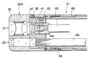
図2及び図3は第1実施例の先端光学アダプタ30Aであり、前記内視鏡先端部21の内部には1つのCCD41及びIC42などの電気部品や信号ケーブル43をCCD背面からケーブル接続部まで接着剤で一体的に封止して成形した撮像ユニット44とライトガイド45とが配設されている。前記ライトガイド45は、内視鏡先端部先端側で二股に分岐して図3に示すように先端光学アダプタ30Aに設けた2つの照明光学系33,33に臨まれるようになっている。また、内視鏡先端部21の外周面にはアダプタ着脱用ねじ46が固定されている。なお、符合47は先端光学アダプタ30の光学系と内視鏡2の光学系とが対設するように位置決めを行う位置決め溝である
図に示す先端光学アダプタ30Aは、前記内視鏡先端部21に内蔵した1つのCCD41に1つの被写体像が結像するように対物光学系31を設けた通常観察用の先端光学アダプタ30Aである。前記先端光学アダプタ30Aの硬性部32には対物光学系31及び2つの照明光学系33,33が内設されると共に、この硬性部32の手元側内周面には内視鏡先端部21に着脱自在に接続するための接続手段としてねじ部34が形成してある。なお、符号35は前記位置決め溝47に配設される位置決めピンである
上述の先端光学アダプタ30Aと内視鏡先端部21とは、前記内視鏡先端部21の外周面に設けたアダプタ着脱用ねじ46と先端光学アダプタ30Aの内周面に形成したネジ部34とを螺合することで一体的に接続される。このとき、前記位置決め溝47に位置決めピン35が配設されることにより、CCD41の光軸中心と対物光学系32の光軸中心とが一致して通常の内視鏡画像を得て内視鏡観察を行う内視鏡2が構成される。
【0020】
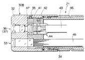
図4及び図5を参照して別の構成の先端光学アダプタ30を説明する。
図に示す第2実施例の先端光学アダプタ30Bは、前記内視鏡先端部21に内蔵した1つのCCD41に2つの被写体像が結像するように2つの対物光学系36,37を設けたものであり、この先端光学アダプタ30Bの硬性部32には対物光学系36,37と2つの照明光学系33,33とが内設されている。
なお、前記対物光学系36,37は、同一機能の光学系であっても、異なる機能の光学系であってもよい。
【0021】
まず、2つの対物光学系36,37の機能が異なるものについて説明する。 図に示す先端光学アダプタ30Bに設けた対物光学系36と対物光学系37とは例えば、観察深度と明るさとが異なるものであり、対物光学系36は近点にピントを合わせて且つ絞りを絞って構成したものであり、対物光学系37は遠点にピントを合わせて且つ絞りを開いて構成したものである。その他の構成は前記第1実施例の先端光学アダプタの構成と同様であり、同部材には同符号を付して説明を省略する。
【0022】
このため、前記先端光学アダプタ30Bを内視鏡先端部21に接続することによって、近点の被検体の観察を対物光学系36を用いて行い、遠点の被検体の観察を対物光学系37を用いて行うことによって近点から遠点までの観察が行える内視鏡が構成される。なお、前記先端光学アダプタ30Bは、観察深度と明るさとが異なるものに限定されるものではなく、例えば画角が異なるものであってもよい。この場合、対物光学系36の画角を例えば30°に設定した狭角の望遠仕様とし、対物光学系37の画角を例えば120°に設定した広角のワイド仕様などにする。
【0023】
このことにより、観察を行う場合にはまず、対物光学系37で広範囲の画像を観察した後に、詳細に拡大して観察したい所を対物光学系36でズームレンズを用いたようにテレ/ワイドの観察を行うことができる。このとき、照明光学系33,33に配設される照明レンズをそれぞれ対物光学系36,37の仕様に対応させて狭角用、広角用として構成することにより、対物光学系36,37を用いて更に効果的な観察を行うことができる。また、狭角仕様の前記対物光学系36をタービン観察に使用し、広角仕様の対物光学系37をパイプ観察に使用するというような使い方もできる。
【0024】
また、図6及び図7に示すように一方の対物光学系及び照明光学系と他方の対物光学系及び照明光学系との視野方向を異なるように組み合わせて先端光学アダプタ30Cを形成してもよい。
【0025】
図に示すように一方の対物光学系38の観察面が内視鏡の軸方向を向いた直視型とし、他方の対物光学系39の観察面が内視鏡の軸方向に対して直角方向を向いた側視型とし、これら対物光学系38,39の仕様に対応させて照明光学系33,33をそれぞれ直視型用と、側視型用とにしている。その他の構成は前記第1実施例の先端光学アダプタの構成と同様であり、同部材には同符号を付して説明を省略する。
【0026】
このため、前記先端光学アダプタ30Cを内視鏡先端部21に接続することによって、内視鏡先端部に位置する被検体の観察を直視型の対物光学系38を用いて行い、内視鏡先端部側面に位置する被検体の観察を側視型の対物光学系39を用いて行うことによって、パンビュー機能を有するように直視と側視の両方向の観察が行える内視鏡が構成される。
【0027】
さらに、図8に示すように先端光学アダプタ30Dの対物光学系40A,40Bを異なる方向を向く斜視型としている。この場合の2つの照明光学系33,33も前記対物光学系40A,40Bに対応した方向を照明するように形成されている。その他の構成は前記第1実施例に示した先端光学アダプタの構成と同様であり、同部材には同符号を付して説明を省略する。
【0028】
このため、前記先端光学アダプタ30Dを内視鏡先端部21に接続することによって、内視鏡先端部に対して斜めの方向を向く対物光学系40A,40Bを用いて広範囲の画像を得て被検体の観察を行える内視鏡が構成される。なお、両方の対物光学系を斜視にするのではなく、一方だけを斜視型にして他方を直視型あるいは側視型として構成してもよいことはいうまでもない。
【0029】
なお、上述で説明したように観察深度と明るさとが異なる対物光学系を組み合わせて構成した先端光学アダプタ30Bや、視野方向が異なる対物光学系を組み合わせて構成した先端光学アダプタ30Cや画角の異なる対物光学系を組み合わせて構成した先端光学アダプタなど、複数の対物光学系を設けて1つのCCD上に複数の光学像を結像させて観察画像を得る場合、それぞれの対物光学系に対応するように内視鏡先端部の先端側で二股に分岐させて配置されているライトガイドから同じ光量の照明光を出射していたのでは、一方の対物光学系で得られる観察画像と他方の対物光学系で得られる観察画像との間に、それぞれの対物光学系のFナンバーの違いなどによる差が生じて、適正な明るさの観察画像を得られなくなる。このため、1つのCCD上に複数の対物光学系を介して結像させた複数の光学像から得られるそれぞれの観察画像の明るさを適正な明るさにする必要がある。
【0030】
そこで、図9に示すように映像信号の元になる信号を取り出すCDS回路51と、CCD41の撮像面を左半分、右半分、または通常の全画面に切換える画面切換え回路52と、標準のTV信号を生成する映像信号処理回路53と、適正な明るさの観察画像を得るように光源装置3からライトガイドコネクタ28に供給される照明光の光量を制御する制御信号を出力する調光回路54と、前記画面切換え回路52を制御する画面セレクター55とを配設し、この画面セレクター55に制御装置4のパネル面に設けた切換スイッチ56を接続して制御装置4を構成している。そして、1つのCCDで適正な明るさの2つの観察画像を得るための光量制御系50を、前記制御装置4のCDS回路51,画面切換え回路52,調光回路54,画面セレクター55及び切換スイッチ56で形成している。
【0031】
すなわち、1つのCCD上に結像した光学像から得られる観察画像の一方の明るさが適正でない場合、切換スイッチ56を操作して明るさが適正でないCCD41の撮像面の左半分あるいは右半分のどちらか一方を選択する。すると、この切換スイッチ56で選択された制御信号に基づいて画面セレクター55ではCCD41の水平方向の画素数をカウントして、撮像面の左半分のみを表示させるための信号あるいは右半分のみを表示させるための信号を画面切替回路52に送り、この画面切替回路52で最終的な画面切換え操作を行う。
【0032】
そして、前記画面切替回路52によって選択したCCD41の撮像面に結像した光学像の光電変換した電気信号を調光回路54へ伝送する。この調光回路54では、選択されたCCD41の撮像面から送られてきた光学像の電気信号の輝度情報を基に、光源装置3から出射される照明光の光量調整を行うため、光源装置3に設けられている例えば絞り羽根(不図示)を駆動するための制御信号を生成する。この調光回路54で生成された制御信号を光源装置3に出力して絞り羽根の調整を行う。すると、光源装置3から内視鏡2を介して先端光学アダプタに設けられているそれぞれの対物光学系に対応する照明光学系に適正な光量の照明光が供給される。このことにより、対象物に向かって先端光学アダプタの照明光学系から出射される照明光の光量がそれぞれの対物光学系に応じた明るさに適宜調整されるので、1つのCCDで適正な明るさの2つの観察画像を得ることができる。
【0033】
次に、前記2つの対物光学系の機能が同じものについて説明する。
前記図4に示したとほぼ同様の構成の先端光学アダプタに設けられている2つの対物光学系36,37の機能が同じである先端光学アダプタ30Eの場合、図10に示すように先端光学アダプタ30Eを接続した内視鏡2を備えて構成される内視鏡装置1には画像切換装置6を設けている。
【0034】
このため、前記先端光学アダプタ30Eを内視鏡先端部21に接続することによって、画像切換装置6には対物光学系36,37を介してCCDの異なる位置に撮像された被検体の映像信号が制御装置4を介して伝送される。そして、これら対物光学系36,37でとらえた被検体の映像信号をA/D変換器61,メモリ62,画像切換え回路63,D/A変換器64を介して交互にTVモニター5に表示することによって被検部位の立体像が得られる内視鏡が構成される。
【0035】
このように、内視鏡先端部に着脱自在な先端光学アダプタを1つの対物光学系で構成したり、2つの対物光学系を設け近点から遠点までの観察が行えるもの、あるいは広範囲の画像と詳細に拡大した画像とでテレ/ワイドの観察が行えるもの、直視と側視の両方向をパンビュー機能を有するように観察が行えるもの、さらには2つの対物光学系の機能を同じに構成することにより、通常の内視鏡観察,テレ/ワイドな観察,パンビュー観察,立体視観察などに対応する内視鏡装置を容易に構成することができる。
【0036】
また、1つ固体撮像装置を内蔵した内視鏡は、1台の制御装置,画像切換装置で内視鏡装置が構成されているので、この構成を換えることなく、通常の観察の他に、立体視観察や直側/側視などの同時観察、広角/望遠など同時観察が行える内視鏡装置を安価に構成することができる。
【0037】
なお、上述のように機能の異なる対物光学系を配設した先端光学アダプタを内視鏡先端部に接続した内視鏡で構成される内視鏡装置の制御装置4とTVモニター5との間に前記画像切換装置6を配設したり、前記図9に示した画面切替回路52や画面セレクター55や切換スイッチ56を備えた制御装置5にすることによって、立体観察を容易に行えるばかりでなく、TVモニター5に対物光学系でとらえた画像のどちらか一方だけ表示したり、別々に交互に表示したりすることなどができる。また、必要に応じて外部スイッチを切り換えることによって対物光学系でとらえた画像を切り換え表示したり、所望のものを選択してTVモニター5の中央に表示させることによって観察画像が見易くなって検査効率を向上させることができる。さらに、制御装置4とTVモニター5との間に画像切換装置を配設する代わりに、制御装置4に画像切換装置6の機能を持たせてもよいことはいうまでもない。また、上述したように1つのCCD上に2つの対物光学系を介して像を結像させる場合、1つのCCDで1つの画像を得る場合よりフレアーなどの発生が心配される。このため、CCDカバーガラスにフレアー防止用のコーティングをしておくことが望ましい。更に、上述の実施例では複数の対物光学系を2つの対物光学系として説明してきたが、対物光学系は3つ以上であってもよい。
【0038】
次に、図11を参照して内視鏡内を挿通するライトガイドの別の構成を説明する。
上述で説明したように観察深度と明るさとが異なる対物光学系を組み合わせて構成した先端光学アダプタ30Bや、視野方向が異なる対物光学系を組み合わせて構成した先端光学アダプタ30Cや画角の異なる対物光学系を組み合わせて構成した先端光学アダプタなど、複数の対物光学系を設けて1つのCCD上に複数の光学像を結像させて観察画像を得る場合、それぞれの対物光学系に対応するように内視鏡先端部の先端側で二股に分岐させて配置されているライトガイドから同じ光量の照明光を出射していたのでは、一方の対物光学系で得られる観察画像と他方の対物光学系で得られる観察画像との間に、それぞれの対物光学系のFナンバーの違いなどによる差が生じて、適正な明るさの観察画像を得られなくなる。
【0039】
このため、1つのCCD上に複数の対物光学系を介して結像させた複数の光学像から得られるそれぞれの観察画像の明るさを適正な明るさにするため、本実施例では内視鏡70を以下のように構成している。
【0040】
図に示すように本実施例の内視鏡70にはこの内視鏡70の先端部に着脱自在に接続可能な前記先端光学アダプタに設けられている例えば2つの照明光学系が臨まれる位置にそれぞれ第1のライトガイド71及び第2のライトガイド72を配設している。
【0041】
すなわち、内視鏡70には前記図4に示した先端光学アダプタ30Bの対物光学系36に対設する第1の対物光学系73に対応する第1のライトガイド71と、前記先端光学アダプタ30Bの対物光学系37に対設する第2の対物光学系74に対応する第2のライトガイド72とが設けられている。なお、符号71aは前記第1のライトガイド71の第1の照明レンズであり、符号72aは前記第2のライトガイド72の第2の照明レンズである。その他の内視鏡70の構成は前記内視鏡2と同様であり、同部材には同符号を付して説明を省略する。
【0042】
前記第1のライトガイド71及び第2のライトガイド72は、コネクタ27aに設けたライトガイドコネクタ28a,28bを介して光源装置3aに接続されるようになっている。この光源装置3aには前記第1のライトガイド71に照明光を供給するための第1の絞り装置75a,第1の絞り駆動部76a及び第1のランプ77aが設けられると共に、前記第2のライトガイド72に照明光を供給するための第2の絞り装置75b,第2の絞り駆動部76b及び第2のランプ77bが設けられている。
【0043】
上述のように構成した内視鏡70と光源装置3aとを備えた内視鏡装置1で対象物を観察する際、前記第1のライトガイド71を伝送されて先端光学アダプタの照明光学系から出射された照明光に照らされた対象物はCCD41に光学像を結像し、光電変換された光学像の電気信号が制御装置4に伝送される。同様に、前記第2のライトガイド72を伝送されて先端光学アダプタの照明光学系から出射された照明光に照らされた対象物はCCD41に光学像を結像し、光電変換された光学像の電気信号が制御装置4に伝送される。
【0044】
これら光学像の電気信号が伝送される制御装置4では、前記CCD上に結像して得られた光学像の電気信号の中の輝度情報を基に、光源装置3aから対象物に向かって出射される照明光の光量を適正な明るさに調整するための前記第1の絞り装置75aを制御する第1の絞り駆動部76aあるいは前記第2の絞り装置75bを制御する第2の絞り駆動部76bを駆動する制御信号が生成される。
【0045】
前記制御装置4で生成された前記第1の絞り駆動部76aあるいは第2の絞り駆動部76bを駆動させる制御信号は、光源装置3aに出力され、光源装置内に備えられている第1の絞り装置75aあるいは第2の絞り装置75bを構成する例えば絞り羽根を適宜調整し、1つのCCDで得られる複数の観察画像のそれぞれの明るさを適正な明るさに調整する。
【0046】
このように、内視鏡に配設されている複数の対物光学系にそれぞれ対応させてライトガイドを配設し、対象物に向かってライトガイド及び照明光学系を介して出射される照明光の光量を、それぞれの対物光学系で結像させた光学像から得られる電気信号を元に、観察画像の明るさに対応させて適宜調整することができる。このことにより、1つのCCDに結像する複数の観察画像の明るさを適正な明るさにして観察することが可能になる。
【0047】
ところで、内視鏡の観察光学系に観察画像の重力方向を知らしめる指示用鋼球を配設したものがある。この内視鏡を用いて観察を行った場合、観察画像内に指示用鋼球の像が重なって観察がやり難いという不具合があった。このため、図12に示すように2つある対物光学系81,82のうち、一方の対物光学系82に重力方向を検出するための重力方向検出手段として微少の指示用鋼球83を配置している。このことにより、対物光学系81で観察画像を得、対物光学系82で重力方向を知ることができるので観察画像が見易くなる。
【0048】
なお、重力方向を示す指示用鋼球83を入れる対物光学系82は特に結像性能を有する必要はなく、透明な平行平面板の間に挟むようにしても良い。また、重力方向用の画面を観察用の画面より小さくして、観察が容易な観察画像を得るようにすると良い。
【0049】
[付記]
1.1つの固体撮像素子を内蔵した内視鏡の先端側に接続される先端光学アダプタを有する内視鏡装置において、前記内視鏡に着脱自在な先端光学アダプタに同一または異なる複数の対物光学系を設けた内視鏡装置。
【0050】
2.前記内視鏡に単一の対物光学系で構成した先端光学アダプタが接続可能な付記1記載の内視鏡装置。
【0051】
3.前記先端光学アダプタに設ける複数の対物光学系の視野方向が同じである付記1記載の内視鏡装置。
【0052】
4.前記先端光学アダプタに設ける複数の対物光学系の観察深度と絞り値とが互いに異なる付記3記載の内視鏡装置。
【0053】
5.前記先端光学アダプタに設ける複数の対物光学系の画角が互いに異なる付記3記載の内視鏡装置。
【0054】
6.前記先端光学アダプタに設ける複数の対物光学系が同一である付記3記載の内視鏡装置。
【0055】
7.前記複数の同一の対物光学系を通して固体撮像素子に結像した被写体像を画像切換装置を介してモニタ上に表示することによって立体視観察可能な付記6記載の内視鏡装置。
【0056】
8.前記先端光学アダプタに設ける複数の対物光学系の視野方向が互いに異なる付記1記載の内視鏡装置。
【0057】
9.前記先端光学アダプタの一方が直視型で、他方が側視型である付記8記載の内視鏡装置。
【0058】
10.前記先端光学アダプタの一方が直視型で、他方が斜視視型である付記8記載の内視鏡装置。
【0059】
11.前記先端光学アダプタの対物光学系が互いに異なる方向を向く斜視型である付記8記載の内視鏡装置。
【0060】
12.前記先端光学アダプタの対物光学系の一方に、重力方向を検知する重力方向検出手段を配置した付記1記載の内視鏡装置。
【0061】
13.前記先端光学アダプタに設けた複数の対物光学系を介して1つの固体撮像素子の撮像面に結像する複数の光学像の中から任意の撮像面に結像した光学像を選択する選択手段を設けた付記1記載の内視鏡装置。
【0062】
14.前記選択手段を制御装置内に設けた付記13記載の内視鏡装置。
【0063】
15.前記選択手段で選択した光学像の光電変換された電気信号の輝度情報を元に、光源装置からライトガイドに出射される照明光の光量を調整する付記13記載の内視鏡装置。
【0064】
16.前記内視鏡に設けられているライトガイドが内視鏡先端部先端側で複数に分岐して配置されている付記1ないし付記12記載の内視鏡装置。
【0065】
17.前記内視鏡のライトガイドを、この内視鏡に配設されている複数の対物光学系に対応させて複数設けた付記1ないし付記12記載の内視鏡装置。
【0066】
18.前記内視鏡に設けた複数のライトガイドにそれぞれ対応するランプを光源装置に複数設けた付記17記載の内視鏡装置。
【0067】
19.前記光源装置に設けた複数のランプからそれぞれのランプに対応する内視鏡のライトガイドに供給される照明光の光量が独立して制御される付記18記載の内視鏡装置。
【0068】
20.前記先端光学アダプタに設けた照明光学系が各々の観察光学系に対応した照明光を照射するように形成されている付記1ないし付記19記載の内視鏡装置。
【0069】
【発明の効果】
以上説明したように本発明によれば、1つの固体撮像素子を備えた内視鏡で通常の観察の他に、立体視観察やテレ/ワイドの2つの画像観察あるいはパンビューなど種々の機能を簡単な構成で、適正な明るさで観察可能な内視鏡装置を提供することができる。
【図面の簡単な説明】
【図1】図1ないし図9は本発明の一実施例に係り、図1は内視鏡装置の概略構成を示す図
【図2】1つの対物光学系で構成した先端光学アダプタ及び内視鏡先端部の構成を示す断面図
【図3】図2の先端光学アダプタの正面図
【図4】2つの対物光学系で構成した先端光学アダプタ及び内視鏡先端部の構成を示す断面図
【図5】図4の先端光学アダプタの正面図
【図6】2つの対物光学系で構成した先端光学アダプタの別の構成を示す正面図
【図7】図6のI―I断面図
【図8】2つの対物光学系で構成した先端光学アダプタの他の構成を示す断面図
【図9】制御装置の構成の1例を示すブロック図
【図10】その他の構成の先端光学アダプタを内視鏡先端部に接続した内視鏡装置の概略構成を示す図
【図11】先端光学アダプタに接続可能な内視鏡の別の構成を説明する断面図
【図12】重力方向検出用手段を配設した先端光学アダプタの構成を示す断面図
【符号の説明】
1…内視鏡装置
2…内視鏡
30…先端光学アダプタ[0001]
[Industrial application fields]
The present invention relates to an endoscope apparatus having a tip optical adapter connected to an endoscope incorporating a single solid-state imaging device.
[0002]
[Prior art]
2. Description of the Related Art In recent years, endoscopes capable of observing organs in a body cavity by inserting an elongated insertion portion into a body cavity or performing various treatments and treatments using a treatment instrument inserted into a treatment instrument channel as necessary. Widely used. Further, these endoscopes are used not only for medical purposes but also for industrial purposes, for observation and inspection in a pipe of a boiler, a machine, a chemical plant, etc., or in an engine.
[0003]
The endoscope used as described above is provided with an image sensor such as a charge coupled device (hereinafter referred to as CCD) at the distal end of the insertion portion, and the endoscope image formed on the image sensor is displayed on the monitor screen. There are electronic endoscopes that perform observation.
[0004]
In a medical electronic endoscope, a stereoscopic image obtained by forming images obtained by two objective optical systems on one CCD built in an endoscope insertion portion so that stereoscopic observation can be performed. An endoscope is shown in Japanese Patent Application Laid-Open No. 64-26813 and US Pat. No. 5,122,650.
[0005]
Japanese Patent Laid-Open No. 1-177716 has two objective optical systems having different magnifications, and forms an observation image captured by each objective optical system on a CCD corresponding to each objective optical system. Thus, a so-called tele / wide endoscope capable of observing two images of a normal observation image and an enlarged image is shown.
[0006]
On the other hand, as an industrial electronic endoscope, a tip optical adapter type has been conventionally known, and this tip optical adapter has been provided with one type of objective optical system corresponding to the application.
[0007]
In addition, there is a great need for industrial endoscopes used in the industrial field that have a zoom function in the objective optical system or a so-called pan view function that can be switched between direct view and side view by hand operation. It was.
[0008]
[Problems to be solved by the invention]
However, when a mechanism for performing the pan-view function is provided at the distal end portion of the industrial endoscope, the endoscope distal end portion has a large diameter, and the structure is complicated, resulting in an increase in cost.
[0009]
Further, a stereoscopic endoscope capable of performing stereoscopic observation as described in the above Japanese Patent Application Laid-Open No. 64-26813 and US Pat. No. 5,122,650 and a telescope disclosed in Japanese Patent Application Laid-Open No. 1-177716. Endoscopes that can perform wide / wide are dedicated to stereoscopic viewing or tele / wide only.
[0010]
Further, an endoscope that performs stereoscopic observation by forming images obtained by two objective optical systems on the CCD usually uses a pair of optical systems for stereoscopic observation. The numbers (brightness / aperture value) were the same, and common illumination light was sent to both optical systems. In other words, it is not necessary to adjust the amount of illumination light that irradiates the object from the light source through the light guide in correspondence with each optical system, but the observation images captured by the respective objective optical systems are the respective objective optical systems. In an endoscope capable of tele / wide imaging by forming an image on a CCD corresponding to the above, if an illumination with a common light amount is applied to two optical systems having different magnifications, an image having an appropriate brightness for each optical system. Therefore, it is necessary to adjust and supply an appropriate amount of illumination light to each optical system.
[0011]
The present invention has been made in view of the above circumstances, and in addition to normal observation with an endoscope provided with a single solid-state imaging device, various observations such as stereoscopic observation and two tele / wide image observations or pan views are available. An object of the present invention is to provide an endoscope apparatus that can be observed with an appropriate brightness with a simple configuration.
[0012]
[Means for Solving the Problems]
An endoscope apparatus according to the present invention is connected to the distal end side of an endoscope incorporating a single image sensor, and is an illumination optical system.And multiple objective optical systems with different angles of viewAdvanced optical adapterWhen,A plurality of optical images formed on the imaging surface of the imaging element via the plurality of objective optical systems;Selecting means for selecting an optical image formed on an arbitrary imaging surface from the inside, and the optical image selected by the selecting meansThe light quantity of illumination light emitted from the illumination optical system can be adjusted based on luminance information of an electrical signal.To do.
[0013]
[Action]
According to this configuration, the tip optical adapter is appropriately connected to the tip portion of the endoscope by appropriately connecting the tip optical adapter having an objective optical system having functions such as stereoscopic viewing, tele / wide, and pan view. Observations corresponding to the adapter can be performed.
[0014]
【Example】
Embodiments of the present invention will be described below with reference to the drawings.
FIG. 1 to FIG. 9 relate to an embodiment of the present invention, FIG. 1 is a diagram showing a schematic configuration of an endoscope apparatus, and FIG. 2 is a diagram of a distal optical adapter and a distal end portion of an endoscope configured with one objective optical system. 3 is a front view of the distal optical adapter shown in FIG. 2, FIG. 4 is a sectional view showing the configurations of the distal optical adapter and the distal end of the endoscope, which are composed of two objective optical systems, and FIG. FIG. 6 is a front view showing another configuration of the tip optical adapter composed of two objective optical systems, FIG. 7 is a cross-sectional view taken along the line II of FIG. 6, and FIG. FIG. 9 is a cross-sectional view showing another configuration of the distal optical adapter constituted by the optical system, and FIG. 9 is a diagram showing a schematic configuration of an endoscope apparatus in which the distal optical adapter having other configurations is connected to the distal end portion of the endoscope.
[0015]
As shown in FIG. 1, an endoscope apparatus 1 includes an
[0016]
The
[0017]
The
[0018]
The light source device 3, the control device 4, and the
[0019]
Hereinafter, the configuration of the distal optical adapter that is detachably attached to the endoscope
FIGS. 2 and 3 show the distal
The tip
The distal
[0020]
A tip
The distal
The objective
[0021]
First, the different functions of the two objective
[0022]
For this reason, by connecting the distal
[0023]
As a result, when performing observation, first, after observing a wide range of images with the objective
[0024]
Further, as shown in FIGS. 6 and 7, the tip
[0025]
As shown in the figure, the observation surface of one objective
[0026]
For this reason, by connecting the distal
[0027]
Further, as shown in FIG. 8, the objective
[0028]
For this reason, by connecting the distal optical adapter 30D to the endoscope
[0029]
As described above, the tip
[0030]
Therefore, as shown in FIG. 9, a
[0031]
That is, when the brightness of one of the observation images obtained from the optical image formed on one CCD is not appropriate, the changeover switch 56 is operated to adjust the left half or right half of the imaging surface of the
[0032]
Then, an electric signal obtained by photoelectric conversion of the optical image formed on the imaging surface of the
[0033]
Next, the same functions of the two objective optical systems will be described.
In the case of the tip
[0034]
For this reason, by connecting the distal
[0035]
In this way, the distal optical adapter that can be attached to and detached from the endoscope distal end is configured with one objective optical system, or two objective optical systems are provided for observation from near to far points, or a wide range of images. And a magnified image with tele / wide observation, direct observation and side viewing with pan-view function, and the functions of the two objective optical systems are the same This makes it possible to easily configure an endoscope apparatus that supports normal endoscope observation, tele / wide observation, pan-view observation, stereoscopic observation, and the like.
[0036]
In addition, since an endoscope that includes one solid-state imaging device is configured by a single control device and an image switching device, in addition to normal observation without changing this configuration, An endoscope apparatus that can perform stereoscopic observation, simultaneous observation such as direct / side viewing, and simultaneous observation such as wide-angle / telephoto can be configured at low cost.
[0037]
In addition, between the control device 4 and the
[0038]
Next, another configuration of the light guide inserted through the endoscope will be described with reference to FIG.
As described above, the distal
[0039]
For this reason, in order to make the brightness of each observation image obtained from a plurality of optical images formed on one CCD through a plurality of objective optical systems appropriate brightness, in this embodiment, an endoscope is used. 70 is configured as follows.
[0040]
As shown in the figure, the
[0041]
That is, the
[0042]
The
[0043]
When observing an object with the endoscope apparatus 1 including the
[0044]
In the control device 4 to which the electric signal of the optical image is transmitted, the light is emitted from the light source device 3a toward the object based on the luminance information in the electric signal of the optical image obtained by imaging on the CCD. The first diaphragm driving unit 76a for controlling the first diaphragm device 75a for adjusting the light quantity of the illumination light to be appropriate brightness or the second diaphragm driving unit for controlling the
[0045]
A control signal for driving the first diaphragm driving unit 76a or the second
[0046]
In this way, a light guide is provided corresponding to each of the plurality of objective optical systems provided in the endoscope, and the illumination light emitted through the light guide and the illumination optical system toward the object is provided. The amount of light can be appropriately adjusted according to the brightness of the observation image based on the electrical signal obtained from the optical image formed by each objective optical system. This makes it possible to observe the plurality of observation images formed on one CCD with appropriate brightness.
[0047]
By the way, there is an endoscope in which an instruction steel ball for informing the gravity direction of an observation image is provided in an observation optical system of an endoscope. When observation was performed using this endoscope, there was a problem that it was difficult to observe because the images of the indicating steel balls overlapped in the observation image. For this reason, as shown in FIG. 12, one of the two objective
[0048]
It should be noted that the objective optical system 82 in which the indicating
[0049]
[Appendix]
1. An endoscope apparatus having a distal optical adapter connected to the distal end side of an endoscope incorporating a single solid-state imaging device, wherein a plurality of objective optics that are the same as or different from the distal optical adapter detachably attached to the endoscope An endoscopic device provided with a system.
[0050]
2. The endoscope apparatus according to appendix 1, wherein a tip optical adapter configured with a single objective optical system is connectable to the endoscope.
[0051]
3. The endoscope apparatus according to appendix 1, wherein a plurality of objective optical systems provided in the distal optical adapter have the same visual field direction.
[0052]
4). The endoscope apparatus according to appendix 3, wherein the observation depths and aperture values of the plurality of objective optical systems provided in the distal optical adapter are different from each other.
[0053]
5. The endoscope apparatus according to supplementary note 3, wherein the plurality of objective optical systems provided in the distal optical adapter have different angles of view.
[0054]
6). The endoscope apparatus according to appendix 3, wherein a plurality of objective optical systems provided in the distal optical adapter are the same.
[0055]
7). The endoscope apparatus according to appendix 6, wherein stereoscopic images can be observed by displaying a subject image formed on a solid-state imaging device through the plurality of identical objective optical systems on a monitor via an image switching device.
[0056]
8). The endoscope apparatus according to appendix 1, wherein the plurality of objective optical systems provided in the distal optical adapter have different viewing directions.
[0057]
9. The endoscope apparatus according to appendix 8, wherein one of the tip optical adapters is a direct view type and the other is a side view type.
[0058]
10. The endoscope apparatus according to appendix 8, wherein one of the distal optical adapters is a direct view type and the other is a perspective view type.
[0059]
11. The endoscope apparatus according to appendix 8, wherein the objective optical system of the distal optical adapter is a perspective type that faces in different directions.
[0060]
12 The endoscope apparatus according to appendix 1, wherein a gravitational direction detecting means for detecting a gravitational direction is arranged on one of the objective optical systems of the distal optical adapter.
[0061]
13. Selection means for selecting an optical image formed on an arbitrary image pickup surface from a plurality of optical images formed on an image pickup surface of one solid-state image pickup device via a plurality of objective optical systems provided on the tip optical adapter. The endoscope apparatus according to Supplementary Note 1 provided.
[0062]
14 The endoscope apparatus according to attachment 13, wherein the selection unit is provided in a control apparatus.
[0063]
15. The endoscope apparatus according to appendix 13, wherein the light quantity of the illumination light emitted from the light source apparatus to the light guide is adjusted based on luminance information of the electrical signal photoelectrically converted from the optical image selected by the selection unit.
[0064]
16. The endoscope apparatus according to appendix 1 to appendix 12, wherein a light guide provided in the endoscope is branched into a plurality of branches on the distal end side of the endoscope distal end.
[0065]
17. The endoscope apparatus according to any one of supplementary notes 1 to 12, wherein a plurality of light guides of the endoscope are provided in correspondence with a plurality of objective optical systems disposed in the endoscope.
[0066]
18. The endoscope apparatus according to appendix 17, wherein a plurality of lamps respectively corresponding to the plurality of light guides provided in the endoscope are provided in the light source apparatus.
[0067]
19. The endoscope apparatus according to appendix 18, wherein the amount of illumination light supplied to a light guide of an endoscope corresponding to each lamp from a plurality of lamps provided in the light source apparatus is controlled independently.
[0068]
20. The endoscope apparatus according to appendix 1 to appendix 19, wherein an illumination optical system provided in the distal optical adapter is formed so as to irradiate illumination light corresponding to each observation optical system.
[0069]
【The invention's effect】
As described above, according to the present invention, in addition to normal observation with an endoscope having one solid-state imaging device, various functions such as stereoscopic observation, two tele / wide image observations, and pan view are provided. An endoscope apparatus that can be observed with appropriate brightness with a simple configuration can be provided.
[Brief description of the drawings]
FIG. 1 to FIG. 9 relate to an embodiment of the present invention, and FIG. 1 is a diagram showing a schematic configuration of an endoscope apparatus.
FIG. 2 is a cross-sectional view showing a configuration of a distal optical adapter and an endoscope distal end configured with one objective optical system.
3 is a front view of the tip optical adapter of FIG. 2. FIG.
FIG. 4 is a cross-sectional view showing a configuration of a distal optical adapter and an endoscope distal end portion configured by two objective optical systems.
FIG. 5 is a front view of the tip optical adapter of FIG.
FIG. 6 is a front view showing another configuration of the tip optical adapter configured with two objective optical systems.
7 is a cross-sectional view taken along the line II of FIG.
FIG. 8 is a cross-sectional view showing another configuration of the tip optical adapter configured with two objective optical systems.
FIG. 9 is a block diagram showing an example of the configuration of the control device.
FIG. 10 is a diagram showing a schematic configuration of an endoscope apparatus in which a distal optical adapter having another configuration is connected to an endoscope distal end portion.
FIG. 11 is a cross-sectional view illustrating another configuration of the endoscope connectable to the distal optical adapter
FIG. 12 is a cross-sectional view showing the configuration of a tip optical adapter provided with means for detecting the direction of gravity
[Explanation of symbols]
1. Endoscope device
2. Endoscope
30 ... Advanced optical adapter
Claims (1)
Translated fromJapanesePriority Applications (1)
| Application Number | Priority Date | Filing Date | Title |
|---|---|---|---|
| JP14211395AJP3714636B2 (en) | 1994-11-25 | 1995-06-08 | Endoscope device |
Applications Claiming Priority (3)
| Application Number | Priority Date | Filing Date | Title |
|---|---|---|---|
| JP6-291602 | 1994-11-25 | ||
| JP29160294 | 1994-11-25 | ||
| JP14211395AJP3714636B2 (en) | 1994-11-25 | 1995-06-08 | Endoscope device |
Publications (2)
| Publication Number | Publication Date |
|---|---|
| JPH08201706A JPH08201706A (en) | 1996-08-09 |
| JP3714636B2true JP3714636B2 (en) | 2005-11-09 |
Family
ID=26474219
Family Applications (1)
| Application Number | Title | Priority Date | Filing Date |
|---|---|---|---|
| JP14211395AExpired - Fee RelatedJP3714636B2 (en) | 1994-11-25 | 1995-06-08 | Endoscope device |
Country Status (1)
| Country | Link |
|---|---|
| JP (1) | JP3714636B2 (en) |
Families Citing this family (5)
| Publication number | Priority date | Publication date | Assignee | Title |
|---|---|---|---|---|
| US6142930A (en)* | 1997-01-13 | 2000-11-07 | Asahi Kogaku Kogyo Kabushiki Kaisha | Electronic endoscope having compact construction |
| US6095970A (en)* | 1997-02-19 | 2000-08-01 | Asahi Kogaku Kogyo Kabushiki Kaisha | Endoscope |
| JP2001221961A (en)* | 2000-02-09 | 2001-08-17 | Olympus Optical Co Ltd | Binocular optical adapter |
| JP4716595B2 (en) | 2001-04-04 | 2011-07-06 | オリンパス株式会社 | Endoscope apparatus and method for assembling endoscope optical adapter |
| JP2014228851A (en)* | 2013-05-27 | 2014-12-08 | オリンパス株式会社 | Endoscope device, image acquisition method, and image acquisition program |
- 1995
- 1995-06-08JPJP14211395Apatent/JP3714636B2/ennot_activeExpired - Fee Related
Also Published As
| Publication number | Publication date |
|---|---|
| JPH08201706A (en) | 1996-08-09 |
Similar Documents
| Publication | Publication Date | Title |
|---|---|---|
| US6184923B1 (en) | Endoscope with an interchangeable distal end optical adapter | |
| EP1834575B1 (en) | Endoscope-use insertion unit | |
| KR100852310B1 (en) | Endoscope and endoscope system | |
| EP1834572B1 (en) | Endoscope-use insertion unit | |
| US8480566B2 (en) | Solid state illumination for endoscopy | |
| EP1859723B1 (en) | Insertion section for endoscope | |
| US7063663B2 (en) | Endoscopic system with a solid-state light source | |
| US7976459B2 (en) | Portable endoscope for intubation | |
| KR100796415B1 (en) | Endoscopy System and Endoscope | |
| US20010012053A1 (en) | Stereoscopic endoscope system and tv imaging system for endoscope | |
| RU2770743C1 (en) | Electronic endoscope and electronic endoscope system | |
| JP2000245693A (en) | Endoscope device | |
| CN101219045A (en) | Oral Microscope | |
| JP3714636B2 (en) | Endoscope device | |
| JPH0713087A (en) | Hard endoscope device | |
| JPH01293840A (en) | root canal endoscopy | |
| JPH0998943A (en) | Electronic endoscope | |
| JP3034905B2 (en) | Electronic endoscope | |
| JP4388452B2 (en) | Electronic endoscope | |
| JP2003164418A (en) | Endoscope device | |
| JP2007160123A (en) | Endoscope and endoscope system | |
| JPS6088924A (en) | Endoscope device | |
| JP3989061B2 (en) | Rigid sheath for endoscope | |
| JPH01277531A (en) | Endoscopic system |
Legal Events
| Date | Code | Title | Description |
|---|---|---|---|
| A977 | Report on retrieval | Free format text:JAPANESE INTERMEDIATE CODE: A971007 Effective date:20040407 | |
| A131 | Notification of reasons for refusal | Free format text:JAPANESE INTERMEDIATE CODE: A131 Effective date:20040928 | |
| A521 | Written amendment | Free format text:JAPANESE INTERMEDIATE CODE: A523 Effective date:20041129 | |
| A131 | Notification of reasons for refusal | Free format text:JAPANESE INTERMEDIATE CODE: A131 Effective date:20050111 | |
| A02 | Decision of refusal | Free format text:JAPANESE INTERMEDIATE CODE: A02 Effective date:20050510 | |
| A521 | Written amendment | Free format text:JAPANESE INTERMEDIATE CODE: A523 Effective date:20050708 | |
| A911 | Transfer of reconsideration by examiner before appeal (zenchi) | Free format text:JAPANESE INTERMEDIATE CODE: A911 Effective date:20050720 | |
| TRDD | Decision of grant or rejection written | ||
| A01 | Written decision to grant a patent or to grant a registration (utility model) | Free format text:JAPANESE INTERMEDIATE CODE: A01 Effective date:20050817 | |
| A61 | First payment of annual fees (during grant procedure) | Free format text:JAPANESE INTERMEDIATE CODE: A61 Effective date:20050822 | |
| FPAY | Renewal fee payment (event date is renewal date of database) | Free format text:PAYMENT UNTIL: 20080902 Year of fee payment:3 | |
| FPAY | Renewal fee payment (event date is renewal date of database) | Free format text:PAYMENT UNTIL: 20090902 Year of fee payment:4 | |
| FPAY | Renewal fee payment (event date is renewal date of database) | Free format text:PAYMENT UNTIL: 20090902 Year of fee payment:4 | |
| FPAY | Renewal fee payment (event date is renewal date of database) | Free format text:PAYMENT UNTIL: 20100902 Year of fee payment:5 | |
| FPAY | Renewal fee payment (event date is renewal date of database) | Free format text:PAYMENT UNTIL: 20110902 Year of fee payment:6 | |
| FPAY | Renewal fee payment (event date is renewal date of database) | Free format text:PAYMENT UNTIL: 20120902 Year of fee payment:7 | |
| FPAY | Renewal fee payment (event date is renewal date of database) | Free format text:PAYMENT UNTIL: 20130902 Year of fee payment:8 | |
| LAPS | Cancellation because of no payment of annual fees |