JP3714613B2 - Storage device, information processing device including the storage device, and information storage system recovery method - Google Patents
Storage device, information processing device including the storage device, and information storage system recovery methodDownload PDFInfo
- Publication number
- JP3714613B2 JP3714613B2JP2001378580AJP2001378580AJP3714613B2JP 3714613 B2JP3714613 B2JP 3714613B2JP 2001378580 AJP2001378580 AJP 2001378580AJP 2001378580 AJP2001378580 AJP 2001378580AJP 3714613 B2JP3714613 B2JP 3714613B2
- Authority
- JP
- Japan
- Prior art keywords
- point
- controller
- failure
- information processing
- array
- Prior art date
- Legal status (The legal status is an assumption and is not a legal conclusion. Google has not performed a legal analysis and makes no representation as to the accuracy of the status listed.)
- Expired - Fee Related
Links
Images


Classifications
- G—PHYSICS
- G06—COMPUTING OR CALCULATING; COUNTING
- G06F—ELECTRIC DIGITAL DATA PROCESSING
- G06F11/00—Error detection; Error correction; Monitoring
- G06F11/07—Responding to the occurrence of a fault, e.g. fault tolerance
- G06F11/16—Error detection or correction of the data by redundancy in hardware
- G06F11/20—Error detection or correction of the data by redundancy in hardware using active fault-masking, e.g. by switching out faulty elements or by switching in spare elements
- G06F11/2053—Error detection or correction of the data by redundancy in hardware using active fault-masking, e.g. by switching out faulty elements or by switching in spare elements where persistent mass storage functionality or persistent mass storage control functionality is redundant
- G06F11/2089—Redundant storage control functionality
- G—PHYSICS
- G06—COMPUTING OR CALCULATING; COUNTING
- G06F—ELECTRIC DIGITAL DATA PROCESSING
- G06F1/00—Details not covered by groups G06F3/00 - G06F13/00 and G06F21/00
- G06F1/16—Constructional details or arrangements
- G06F1/18—Packaging or power distribution
- G06F1/183—Internal mounting support structures, e.g. for printed circuit boards, internal connecting means
- G06F1/184—Mounting of motherboards
- G—PHYSICS
- G06—COMPUTING OR CALCULATING; COUNTING
- G06F—ELECTRIC DIGITAL DATA PROCESSING
- G06F1/00—Details not covered by groups G06F3/00 - G06F13/00 and G06F21/00
- G06F1/16—Constructional details or arrangements
- G06F1/18—Packaging or power distribution
- G06F1/183—Internal mounting support structures, e.g. for printed circuit boards, internal connecting means
- G06F1/187—Mounting of fixed and removable disk drives
- G—PHYSICS
- G06—COMPUTING OR CALCULATING; COUNTING
- G06F—ELECTRIC DIGITAL DATA PROCESSING
- G06F11/00—Error detection; Error correction; Monitoring
- G06F11/07—Responding to the occurrence of a fault, e.g. fault tolerance
- G06F11/16—Error detection or correction of the data by redundancy in hardware
- G06F11/20—Error detection or correction of the data by redundancy in hardware using active fault-masking, e.g. by switching out faulty elements or by switching in spare elements
- G06F11/202—Error detection or correction of the data by redundancy in hardware using active fault-masking, e.g. by switching out faulty elements or by switching in spare elements where processing functionality is redundant
- G06F11/2023—Failover techniques
- G06F11/2033—Failover techniques switching over of hardware resources
- G—PHYSICS
- G06—COMPUTING OR CALCULATING; COUNTING
- G06F—ELECTRIC DIGITAL DATA PROCESSING
- G06F3/00—Input arrangements for transferring data to be processed into a form capable of being handled by the computer; Output arrangements for transferring data from processing unit to output unit, e.g. interface arrangements
- G06F3/06—Digital input from, or digital output to, record carriers, e.g. RAID, emulated record carriers or networked record carriers
- G06F3/0601—Interfaces specially adapted for storage systems
- G06F3/0602—Interfaces specially adapted for storage systems specifically adapted to achieve a particular effect
- G06F3/0614—Improving the reliability of storage systems
- G06F3/0617—Improving the reliability of storage systems in relation to availability
- G—PHYSICS
- G06—COMPUTING OR CALCULATING; COUNTING
- G06F—ELECTRIC DIGITAL DATA PROCESSING
- G06F3/00—Input arrangements for transferring data to be processed into a form capable of being handled by the computer; Output arrangements for transferring data from processing unit to output unit, e.g. interface arrangements
- G06F3/06—Digital input from, or digital output to, record carriers, e.g. RAID, emulated record carriers or networked record carriers
- G06F3/0601—Interfaces specially adapted for storage systems
- G06F3/0628—Interfaces specially adapted for storage systems making use of a particular technique
- G06F3/0629—Configuration or reconfiguration of storage systems
- G06F3/0635—Configuration or reconfiguration of storage systems by changing the path, e.g. traffic rerouting, path reconfiguration
- G—PHYSICS
- G06—COMPUTING OR CALCULATING; COUNTING
- G06F—ELECTRIC DIGITAL DATA PROCESSING
- G06F3/00—Input arrangements for transferring data to be processed into a form capable of being handled by the computer; Output arrangements for transferring data from processing unit to output unit, e.g. interface arrangements
- G06F3/06—Digital input from, or digital output to, record carriers, e.g. RAID, emulated record carriers or networked record carriers
- G06F3/0601—Interfaces specially adapted for storage systems
- G06F3/0668—Interfaces specially adapted for storage systems adopting a particular infrastructure
- G06F3/0671—In-line storage system
- G06F3/0683—Plurality of storage devices
- G06F3/0689—Disk arrays, e.g. RAID, JBOD
- G—PHYSICS
- G06—COMPUTING OR CALCULATING; COUNTING
- G06F—ELECTRIC DIGITAL DATA PROCESSING
- G06F3/00—Input arrangements for transferring data to be processed into a form capable of being handled by the computer; Output arrangements for transferring data from processing unit to output unit, e.g. interface arrangements
- G06F3/06—Digital input from, or digital output to, record carriers, e.g. RAID, emulated record carriers or networked record carriers
- G06F3/0601—Interfaces specially adapted for storage systems
- G06F3/0628—Interfaces specially adapted for storage systems making use of a particular technique
- G06F3/0655—Vertical data movement, i.e. input-output transfer; data movement between one or more hosts and one or more storage devices
- G06F3/0658—Controller construction arrangements
Landscapes
- Engineering & Computer Science (AREA)
- Theoretical Computer Science (AREA)
- Physics & Mathematics (AREA)
- General Engineering & Computer Science (AREA)
- General Physics & Mathematics (AREA)
- Human Computer Interaction (AREA)
- Computer Hardware Design (AREA)
- Power Engineering (AREA)
- Quality & Reliability (AREA)
- Computer Networks & Wireless Communication (AREA)
- Hardware Redundancy (AREA)
- Debugging And Monitoring (AREA)
Description
Translated fromJapanese【0001】
【発明の属する技術分野】
本発明は、情報記憶に関し、より詳細には、シリアル・インタフェイスによりコンピュータといった情報処理手段に接続される冗長記録方式を用いる記憶装置、該記憶装置を含む情報処理装置および情報記憶システムのリカバリ方法に関する。
【0002】
【従来技術】
これまで、記憶装置に対して冗長性を付与することにより、データの保存性を改善することが提案されてきている。記憶装置に対して冗長性を付与することは、これまで多くの場合、ハード・ディスクといった記憶媒体を複数含んで構成されるアレイを複数使用して、複数のアレイに対して情報を書込む、いわゆるRAID(Redundant Array of Inexpensive Disks)システムといった情報記憶システムを使用することにより行われている。
【0003】
より具体的に冗長性を付与した記憶装置については、これまで(1)RAIDシステムに対して冗長性を与えるべく、複数のコントローラと、ハード・ディスク・ドライブといった記憶媒体とを、パラレルSCSIバスといったバス共有型のインタフェイスを使用して接続する方法、(2)ファイバー・チャネル・アービトレーテッド・ループといったデュアル・ループ型のインタフェイスを用いて、複数のコントローラと、ハード・ディスク・ドライブといった記憶媒体とをループとしてコントローラを接続する方法などを用いて構成されている。
【0004】
上述した従来提案されているRAIDシステムは、共有型のバス・インタフェイスを使用することを前提として構成されている。上述した共有型のバス・インタフェイスとしては、具体的にはSCSI、ファイバ・チャネル、ATAなどのインタフェイスを挙げることができる。上述したインタフェイスまたはコントローラのうちSCSIまたはファイバ・チャネルによりサポートされる記憶媒体は、サーバといった高い信頼性が要求される用途に多くの場合に用いられている。また、ATAといったインタフェイスによりサポートされる記憶媒体は、インタフェイスまたはコントローラの価格といった点から、デスクトップ・パーソナル・コンピュータといった用途において多くの場合に利用されている。
【0005】
図17には、これまで知られているATAインタフェイスを使用してRAIDシステムを構成する場合の概略図を示す。図17に示すように、コントローラ90は、複数のアレイ92、94へと接続され、これらのアレイ92、94を管理している。それぞれのアレイ92、94は、例えばハード・ディスクといった記憶媒体96を単一で、または複数使用して構成されており、それぞれの記憶媒体96に対して記録が行われる構成とされている。コントローラ90には、RAIDシステムに含まれる記憶媒体から構成されるアレイ92、94を制御するためのATAインタフェイス98が含まれていて、それぞれのアレイ92、94に対して記録を可能とさせている。ATAインタフェイス98は、マイクロ・コンピュータ、サーバといったホスト・コンピュータと適切なインタフェイスにより接続されていて、データの転送を行う構成とされている。
【0006】
図18には、図17に示した従来のATAインタフェイスを用いるRAIDシステムのより詳細なブロック図を示す。図18に示されるように、コントローラ90は、ファイバ・チャネル・コネクタ100と、ファイバ・チャネル−ホスト・プロトコル制御手段102と、プロセッサ104と、このプロセッサ104に接続されたキャッシュ・メモリ106とを含んで構成されている。コントローラ90は、ファイバ・チャネル・コネクタ100を介して他のRAIDシステムやホスト・コンピュータと通信を行っており、コントローラ90が受信したデータは、プロトコル制御手段102を介して適切なプロトコルへと変換され、プロセッサ104により適切なアドレスの記憶媒体96へと記録される構成とされている。
【0007】
また、図18に示されるように従来のATAインタフェイス98は、適切なコネクタ手段108を介してそれぞれの記憶媒体96へと接続され、これらの記憶媒体を管理しておりホスト・コンピュータと、記憶媒体との間でATAインタフェイス98を介してデータの転送を可能としている。
【0008】
上述したATAインタフェイス98は、近年ではデータ転送速度の点からATA/100といったパラレル転送技術を使用してデータ転送を行なうことが多い。上述したように、ATAは、低価格であるが、パラレル転送を使用するインタフェイスであるが故に、データ転送速度に制限があることが知られており、これまでATAのデータ転送速度を向上させるべく、種々の試みが行われてきている。例えば上述したATA/100といった転送モードが提案されており、この転送モードでは、16ビットのデータ幅で、クロック周波数が50MHz、最大転送速度100Mbytes/sのデータ転送速度が達成されている。さらにデータ転送速度を向上させるため、データ幅を2倍の32ビットに拡張する、ストローブ信号の周波数を高めるといった試みもなされている。
【0009】
しかしながら、データ幅を増加させたり、ストローブ信号の周波数を高めると、信号線間のデータの同期を取ることが困難となること、信号線間の干渉やノイズが無視できなくなることなどの不都合が生じることが知られている。このため、ATAインタフェイスでは、UltraDMAmode3(44.4Mバイト/s)以上の転送速度を用いる場合、例えばそれぞれグランドを伴う80芯のフラット・ケーブルを用いる40ピンのコネクタを使用し、各信号線間の干渉が防止されている。
【0010】
またさらに、近年では、コンピュータ・システムの高速化、データ量の増大に伴い、さらにインタフェイスまたはコントローラのデータ転送速度は、その向上が要求されている現状にある。このため、図17および図18に示されるRAIDシステムに対して、従来のATAインタフェイスを使用して冗長性を導入することには、データ転送速度、および信号線の取り扱い性、データ転送の信頼性といった点から不都合があった。
【0011】
加えて、コンピュータ・システムの高速化・大容量化およびネットワーク化にともない、データの高付加価値化が進むにつれ、データの保存性を確保するため冗長性が付与された情報記憶システムを使用することがますます要求されている。このため、記憶媒体の記憶容量の増加、および冗長性の付加による記憶装置のコンピュータ・システムに占めるコストが高まり、特に冗長性を付与した記憶装置においては、記憶装置と、コンピュータとの間のインタフェイスまたはコントローラについても、より高速、かつ高コスト・パフォーマンス化を達成することが必要とされることになる。
【0012】
このような要求は、記憶装置がサーバから切り離され、独立したストレージ・エリア・ネットワーク(Storage Area Network: SAN)としてファイバ・チャネルでサーバに接続されるシステムや、イーサネット(登録商標)経由でサーバに接続されて利用される場合がますます高まるものと考えられる。したがって、記憶装置に対して冗長性を付与することが高まることと相俟って、これまでコンピュータと、記憶装置との間のインタフェイスの高速化と、高コスト・パフォーマンス化とを達成することを可能とする、冗長記録方式を用いる記憶装置、該記憶装置を含む情報処理装置および記憶装置のリカバリ方法が必要とされていた。
【0013】
【発明が解決しようとする課題】
本発明は、上記課題に鑑みなされたものであり、本発明は、さらに増大する記憶容量およびデータ転送速度の向上、データ保存性を高めることによるシステムの信頼性の向上、それに伴う情報記憶システムを含む全体のコスト・パフォーマンスの向上を達成することを可能とする、冗長記録方式を用いる記憶装置、該記憶装置を含む情報処理装置および情報記憶システムのリカバリ方法を提供することを目的とする。
【0014】
【課題を解決するための手段】
本発明は、ポイント−ツウ−ポイント・コントローラ(以下、コントローラと略する。)を、ホスト・コンピュータと記録装置とのデータ転送に使用することにより、冗長性を付与しつつ、記憶容量の増大、データ転送速度の向上、データ保存性の向上、コスト・パフォーマンスを改善する、記憶装置、該記憶装置を含む情報処理装置および情報記憶システムのリカバリ方法を提供することができるという着想のもとになされたものである。本発明において使用する用語「ポイント−ツウ−ポイント・コントローラ」とは、デバイスのマスタ/スレーブの区別を使用することなく、レジスタ構成上では、マスタ・デバイスのみが接続されているものとして処理することを可能とするコントローラであって、コントローラとコントローラに接続されるデバイスとがそれぞれ1対1で接続することを可能とするコントローラをいう。
【0015】
すなわち、本発明は、ホスト・コンピュータと、記録装置とのインタフェイスとしてポイント−ツウ−ポイント・コントローラを使用する。コントローラは、好ましい実施の形態においては、RAIDシステムを構成するアレイにそれぞれ対応して設けられる。アレイは、単一または複数の記憶媒体を含んで構成されており、いわゆる冗長記録を可能とする構成とされている。アレイに含まれるそれぞれの記憶媒体は、スイッチング手段を介してポイント−ツウ−ポイント・コントローラへと接続されており、通常の状態では、スイッチング手段を介して1つのアレイが対応する1つのコントローラにより管理され、他のアレイが他のコントローラにより管理されて、アレイのミラー・コピーなどを生成することにより、冗長性を付与する構成とされている。
【0016】
RAIDシステムを管理するコントローラが正常に機能しなくなると、本発明においては、スイッチング手段が障害の生じたコントローラにより管理されるアレイを正常なコントローラに管理させるべく接続させ、その管理権を正常動作する側のコントローラに移転させ記録装置の冗長性を確保する構成とされている。
【0017】
すなわち、本発明によれば、情報処理手段との間でデータを書込み・読出しするための記録装置であって、該記録装置は、
それぞれ少なくとも1つの記憶媒体を含んで構成される複数のアレイと、
前記複数のアレイそれぞれを管理し、相互通信するとともに、すべての前記記憶媒体に接続可能な複数のポイント−ツウ−ポイント・コントローラと、
前記アレイを管理するポイント−ツウ−ポイント・コントローラを切り換えるためのスイッチング手段と、
前記ポイント−ツウ−ポイント・コントローラの障害を検知するための手段と、
前記ポイント−ツウ−ポイント・コントローラの障害の検知に応答して前記スイッチング手段を駆動するための手段とを含み、
前記スイッチング手段は、前記障害の検知に応答して前記ポイント−ツウ−ポイント・コントローラによる前記アレイの管理状態を変更する記憶装置が提供される。
【0018】
本発明の記憶装置においては、前記アレイは、複数の記憶媒体を含むRAIDシステムを構成することが好ましい。本発明においては、前記スイッチング手段を駆動するための手段は、前記ポイント−ツウ−ポイント・コントローラに付された識別子と、該識別子に対応するポイント−ツウ−ポイント・コントローラが管理する記憶媒体を特定する媒体識別子とを対応させたテーブルを含むことができる。本発明の記憶装置においては、前記ポイント−ツウ−ポイント・コントローラは、ポイント−ツウ−ポイント・コントローラの障害を検知して、障害の発生した側のポイント−ツウ−ポイント・コントローラに固有の識別子を取得し、前記管理状態を変更するための所定の処理を実行させるための手段を含むことができる。
【0019】
本発明の記憶装置においては、前記情報処理手段は、前記ポイント−ツウ−ポイント・コントローラの障害を検知するための手段を含み、前記ポイント−ツウ−ポイント・コントローラは、前記情報処理手段からの障害の検知の通知に応答して障害が発生したポイント−ツウ−ポイント・コントローラに固有の識別子を取得して、前記管理状態を変更するための所定の処理を実行させる手段を含むことができる。本発明の記憶装置においては、前記アレイの管理状態の変更は、障害の発生していないポイント−ツウ−ポイント・コントローラに障害の発生したポイント−ツウ−ポイント・コントローラに割当てられたアレイを管理させることができる。本発明の記憶装置においては、前記ポイント−ツウ−ポイント・コントローラは、シリアルATAインタフェイスを含んで構成されることが好ましい。
【0020】
また、本発明においては、情報処理手段と、前記情報処理手段との間でデータを書込み・読出しを実行する記憶手段とを含んで構成される情報処理装置であって、
前記記憶手段は、
少なくとも1つの記憶媒体を含んで構成される複数のアレイと、
前記複数のアレイそれぞれを管理し、互いに相互通信するとともに、すべての前記記憶媒体に接続可能なポイント−ツウ−ポイント・コントローラと、
前記アレイを管理するポイント−ツウ−ポイント・コントローラを切り換えるためのスイッチング手段と、
前記ポイント−ツウ−ポイント・コントローラの障害を検知するための手段と、
前記ポイント−ツウ−ポイント・コントローラの障害の検知に対応して前記スイッチング手段を駆動するための手段とを含み、
前記スイッチング手段は、前記障害の検知に対応して前記ポイント−ツウ−ポイント・コントローラによる前記アレイの管理状態を変更する情報処理装置が提供される。
【0021】
本発明の情報処理装置においては、前記アレイは、複数の記憶媒体を含むRAIDシステムを構成することが好ましい。本発明の情報処理装置においては、前記スイッチング手段を駆動するための手段は、前記ポイント−ツウ−ポイント・コントローラに付された識別子と、該識別子に対応するポイント−ツウ−ポイント・コントローラが管理する記憶媒体を特定する媒体識別子とを対応させたテーブルを含むことができる。本発明の情報処理装置においては、前記ポイント−ツウ−ポイント・コントローラは、ポイント−ツウ−ポイント・コントローラの障害を検知して、障害の発生した側のポイント−ツウ−ポイント・コントローラに固有の識別子を取得し、前記管理状態を変更するための所定の処理を実行させるための手段を含むことができる。
【0022】
本発明の情報処理装置においては、前記情報処理手段は、前記ポイント−ツウ−ポイント・コントローラの障害を検知するための手段を含み、前記ポイント−ツウ−ポイント・コントローラは、前記情報処理手段からの障害の検知の通知に応答して障害が発生したポイント−ツウ−ポイント・コントローラに固有の識別子を取得して、前記管理状態を変更するための所定の処理を実行させる手段を含むことができる。本発明の情報処理装置においては、前記アレイの管理状態の変更は、障害の発生していないポイント−ツウ−ポイント・コントローラに障害の発生したポイント−ツウ−ポイント・コントローラに割当てられたアレイを管理させることが好ましい。本発明の情報処理装置においては、前記ポイント−ツウ−ポイント・コントローラは、シリアルATAインタフェイスを含んで構成されることが好ましい。
【0023】
さらに、本発明によれば、それぞれ少なくとも1つの記憶媒体を含んで構成される複数のアレイと、該複数のアレイをそれぞれ管理するようにスイッチ手段を経由して接続され、それぞれ相互通信すると共にすべての前記記憶媒体に接続可能な複数のポイント−ツウ−ポイント・コントローラを含む情報記憶システムにおいて、障害をリカバリする方法であって、
前記ポイント−ツウ−ポイント・コントローラの障害を検知するステップと、
前記障害の検知により前記スイッチング手段を動作させるステップと、
前記スイッチング手段により前記ポイント−ツウ−ポイント・コントローラによる前記アレイの管理状態を変更するステップと
を含む情報記憶システムのリカバリ方法が提供される。
【0024】
本発明のリカバリ方法においては、前記アレイは、複数の記憶媒体を含むRAIDシステムを構成し、前記方法は、前記アレイのリカバリを行うことが好ましい。本発明のリカバリ方法においては、前記スイッチング手段を駆動するステップは、前記ポイント−ツウ−ポイント・コントローラに付された識別子と、該識別子に対応するポイント−ツウ−ポイント・コントローラが管理する記憶媒体を特定する媒体識別子とを対応させたテーブルを参照するステップを含むことができる。本発明のリカバリ方法においては、前記アレイの管理状態を変更するステップは、障害の発生していないポイント−ツウ−ポイント・コントローラに障害の発生したポイント−ツウ−ポイント・コントローラに割当てられたアレイを管理させるステップを含むことができる。
【0025】
本発明のリカバリ方法においては、さらに、ポイント−ツウ−ポイント・コントローラの障害を検知して、障害の発生した側のポイント−ツウ−ポイント・コントローラに固有の識別子を取得するステップと、
前記障害の発生した側のポイント−ツウ−ポイント・コントローラに固有の識別子を使用して前記管理状態を変更するための所定の処理を実行するステップとを含むことができる。本発明のリカバリ方法においては、前記情報処理手段により、ポイント−ツウ−ポイント・コントローラの障害を検知するステップと、
前記ポイント−ツウ−ポイント・コントローラが前記情報処理手段からの障害の検知の通知を受け取るステップと、
前記通知を受け取った後、障害が発生したポイント−ツウ−ポイント・コントローラに固有の識別子を取得するステップと、
前記固有の識別子を使用して前記管理状態を変更するための所定の処理を実行させるステップを含むことができる。本発明のリカバリ方法においては、前記ポイント−ツウ−ポイント・コントローラは、シリアルATAインタフェイスを含んで構成されることが好ましい。
【0026】
【発明の実施の形態】
以下、本発明を図面に示した具体的な実施の形態に沿って説明するが、本発明は、後述する実施の形態に限定されるものではない。
【0027】
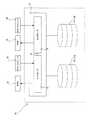
図1は、本発明の冗長記録方式を使用する記録装置10の概略構成を示した図である。なお、図1に示した記憶装置10は、RAIDシステムとしてRAID1の構成を採用し、アレイAが、アレイBのミラー・コピーを与える構成とされている。しかしながら本発明は、図1に示された実施の形態ばかりではなく、RAID0からRAID5のいかなるRAIDシステムに対しても適用することができる。図1に示されるように本発明の記録装置10は、アレイAと、アレイBとを含んで構成されている。アレイAは、単一または複数の記憶媒体を含んで構成されていて、ホスト・コンピュータの要求する記憶容量に適合する記憶容量として構成することができる。
【0028】
また、アレイBについても、単一または複数の記憶媒体を含んで構成することができ、図1に説明する実施の形態においては、アレイBは、アレイAのミラー・コピーを生成して、冗長性のあるデータ保持を可能とさせている。
【0029】
本発明において使用することができる記憶媒体は、特に制限されるものではなく、ハードディスク、CD−R、CD−RW、DVD、MOといった書換え可能ないかなる記憶媒体でも適用することができる。また、本発明においては、上述したアレイAおよびアレイBは、例えばハードディスクといった同一の記憶媒体を含んで構成される別体とされたユニットとして構成することもできるし、ハードディスクを記憶媒体として含むユニットと、MOといった異なった記憶媒体を含んで個別に構成されるユニットとして構成することもできる。
【0030】
アレイAおよびアレイBは、接続部12を介してそれぞれコントローラ14、16へと接続されていて、ホスト・コンピュータからの書込み・読出し要求に応じてデータを転送する構成とされている。コントローラ14と、コントローラ16とは、それぞれの障害をモニタし、また障害時には、正常な側へとデータを転送することができるように、適切なバス・ライン18などにより相互接続されている。コントローラ14、16は、本発明の好適な実施の形態においては、シリアルATA(以下、SATAとして参照する。)を含んで構成されるものを挙げることができる。
【0031】
本発明においてコントローラ14、16に含まれるSATAは、より具体的には、シリアルATAワーキンググループにより策定される規格に準拠するもの、例えばUltraSATA/1500、ATA/ATAPI−6などの他、これらの規格に準拠するものであれば、いかなるものでも含み得るものである。下記表1に、これまで知られているSATAの規格を示す。
【0032】
【表1】
【0033】
図1に示した記憶装置10は、さらに、存在する場合には他のRAIDシステム20およびホスト・コンピュータ22へと接続されていて、必要に応じてデータ容量およびデータ保全性を向上させることができることが示されている。本発明において使用することができるホスト・コンピュータ22としては、これまで知られたいかなるものでも用いることができ、具体的には例えば、パーソナル・コンピュータ、ワークステーションから構成することが可能であり、このパーソナル・コンピュータ、またはワークステーションとしては、PENTIUM(登録商標)、PENTINUM II(登録商標)、PENTINUM III(登録商標)といったCPU、またはこれと互換性のあるCPUを搭載することが可能で、WINDOWS(登録商標)、WINDOWS(登録商標) NT、OS/2(登録商標)、ユニックス、リナックスといったオペレーティング・システムを動作させることが可能なパーソナル・コンピュータ、ワークステーション、またはPowerPC(登録商標)、またはこれに互換性のあるCPUを含みOS/2(登録商標)、AIX(登録商標)、またはMacOS(登録商標)といったオペレーティング・システムを動作させることができるパーソナル・コンピュータまたはワークステーションを挙げることができる。
【0034】
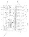
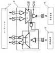
図2には、図1に示した本発明の記憶装置10のコントローラを含む部分の詳細なブロック図を示す。図2に示すようにコントローラ14は、ファイバ・チャネル・コネクタ24と、プロセッサ26と、ファイバ・チャネル・コネクタ24とプロセッサ26とのプロトコルを制御するためのファイバ・チャネル−ホスト・プロトコル制御手段28と、プロセッサ26に接続され転送されるデータを格納するためのキャッシュ・メモリ30と、転送されるデータをアレイAおよびアレイBへと振り分けるためのコントローラ14とを含んで構成されている。上述したコネクタ、プロセッサ、プロトコル変換手段は、上述した構成のものに限定されるものではなく、これまで知られた同等の機能を有するいかなる要素でも用いることができる。
【0035】
図2に示した特定の実施の形態においては、コントローラ14は、SATA32を使用しているのが示されている。以下、本発明においては、説明および本発明を具体的に記述するための目的から、コントローラ14およびコントローラ16は、SATAを用いるものとするが、本発明はSATAインタフェイスに限定されるものではない。
【0036】
図2に示された記憶装置10においては、上述したコントローラ14と、アレイAおよびアレイBとの間は、例えば適切なスイッチング手段を含むコネクタ手段34により接続されているのが示されている。このコネクタ手段34を介して、SATA32は、アレイAおよびアレイBを構成する記憶媒体36a〜36hへと接続可能とされている。図2に示した記録装置の特定の実施の形態においては、SATA32は、通常動作の場合にはそれぞれの記憶媒体36a〜36dへと、図2の実線で示されるように、コネクタ手段34に含まれて構成されているスイッチング手段38を介して接続されている。
【0037】
図2に示す本発明の記録装置10においては、さらにコントローラ14と同様の構成を有する別のコントローラ16が設けられているのが示されている。コントローラ16についても、ファイバ・チャネル・コネクタ40と、ファイバ・チャネル−ホスト・プロトコル制御手段42と、プロセッサ44と、キャッシュ・メモリ46とを含んでおり、通常の状態ではSATA48からコネクタ手段34と、スイッチング手段38とを介してアレイBを構成する記憶媒体36e〜36hへと接続される。図2に示すように、本発明の記憶装置10は、いわゆるRAIDシステムを構成することで、冗長記憶方式に対応可能であることが示されている。
【0038】
また図2には、コントローラ14と、コントローラ16とは、ファイバ・チャネル・コネクタ52、54といった適切な接続手段を介して相互接続されているのが示されている。コントローラ14、16は、後述するように互いに他方のコントローラに障害を生じた場合に、障害を検出することに加え、ミラー・ディスク側のデータをホストに対して負荷を与えることなく転送することを可能とさせている。図2においては、2つのコントローラ14、16が両方とも良好に機能しており、SATA32が記憶媒体36a〜36dを管理し、SATA48が、記憶媒体36e〜37hをそれぞれ管理しているのが実線で示されている。
【0039】
また、図2に示される本発明の記憶装置10には、より詳細にはコントローラに障害が発生したことを検知するための手段が含まれており、コントローラに障害が発生した場合には、適切な方法により障害が発生したことを検知し、障害を検出したプロセッサは、障害が発生していないコントローラ側のSATAを障害の発生した側の記憶媒体に接続させるように、スイッチング手段を駆動することにより障害がリカバリされる。上述したプロセスにより、スイッチング手段52が制御される状態を図2の破線で示す。
【0040】
図3は、本発明の記憶装置10においてアレイAおよびアレイBを制御する、それぞれのコントローラが両方とも正常動作している場合の読み出し動作のプロセスを示したフローチャートである。本発明の記憶装置が正常動作している場合には、まず、ステップS11においてホスト・コンピュータが、特定のコントローラ、例えば特定の実施の形態においては、コントローラ14へと読出し要求を発行する。この読出し要求を受け取ったコントローラ14のプロセッサ26は、ステップS12においてキャッシュ・メモリ30または記憶媒体36a〜36dを検索し、読出し対象のデータが保持されているのが、キャッシュ・メモリ30であれば、キャッシュ・メモリ30からデータを読み出し、ホスト・コンピュータへと転送する。
【0041】
読み出しを行うデータが記憶媒体36a〜36dに保持されている場合には、ステップS13において、コントローラ14が記憶媒体を使用可能か否かを判断し、コントローラ14が記憶媒体を使用可能な場合(yes)には、ステップS14においてプロセッサ26は、記憶媒体36a〜36dのうち、データが保持されている記憶媒体に対して読出し要求を発行し、ステップS15において読出されたデータを、キャッシュ・メモリ28を介してホスト・コンピュータへと転送する。また、コントローラ14が、コントローラ14の障害ではない例えば、記憶媒体のメンテナンス、または記憶媒体自体の障害など何らかの理由で記憶媒体を有していない場合や、アクセスできない場合(no)には、ステップS16において、プロセッサ26は、コントローラ16が管理するミラー・コピーされたデータを読出すべく、プロセッサ44に対して記憶媒体36e〜36hから読出しを行う通知を行う。
【0042】
この通知を受け取ったプロセッサ44は、ステップS17において記憶媒体36e〜36hに対して読出し要求を発行し、ステップS18において読出されたデータをキャッシュ・メモリ46にいったん転送・記憶させた後、キャッシュ・メモリ30へと読出されたデータを転送する。キャッシュ・メモリ30に保持された読出されたデータは、プロセッサ26によりステップS15において、読出し要求を発行したホスト・コンピュータへと転送され、一連の読出し動作が完了する。
【0043】
図4は、本発明の記憶装置10においてアレイAおよびアレイBを制御するそれぞれのコントローラが両方とも正常動作している場合の書込動作のプロセスを示したフローチャートである。図4に示した書込み動作においては、ステップS20においてホスト・コンピュータが、まずコントローラ14へと書込要求を行う。ステップS21において、ホスト・コンピュータから転送されたデータを、キャッシュ・メモリ26へといったん保持させる。その後ステップS22において、コントローラ14が管理する記憶媒体が使用可能か否かを判断する。
【0044】
コントローラ14が管理する記憶媒体36a〜36dが使用可能である場合(yes)には、ステップS23においてキャッシュ・メモリ26から記憶媒体36a〜36dに対して書込を実行させる。また、記憶媒体36a〜36dが使用可能でない場合(no)には、ステップS24においてキャッシュ・メモリ30からキャッシュ・メモリ46へとデータを転送し、プロセッサ44により記憶媒体36e〜36hに対して書込を実行させ、一連の動作を終了する。
【0045】
図5は、本発明の記憶装置10において、コントローラ16に障害が発生した場合に、障害をリカバリするべくスイッチング手段が動作された特定の実施の形態を示す。図5に示すように、コントローラ16に何らかの理由により障害が発生していて、正常なレスポンスを行わないものとする。この段階で、コントローラ16の障害をプロセッサ26が検知すると、プロセッサ26がスイッチング手段38を駆動してコントローラ14に含まれるSATA32に対し、コントローラ16が管理するべき記憶媒体36e〜36hの管理を実行させるべく、SATA32を元々コントローラ16が管理権を所有していた記憶媒体36e〜36hへと接続して、記憶媒体36e〜36hの管理権を取得する。
【0046】
図6は、本発明の記録装置においてコントローラの障害が生じた場合のリカバリ・プロセスの概略的なフローチャートを示した図である。図6に示されるリカバリ・プロセスは、ステップS30において所定の方法にしたがって、コントローラ間の障害をモニタし、ステップS31においてプロセッサ間の通信が正常か否かを判断する。正常な場合(no)には、ステップS32においてホスト・コンピュータが要求するコントローラを経由して、図3および図4に示した通常の書込・読出し動作を実行させる。
【0047】
いずれかのコントローラに障害が発生したことが判断された場合(yes)には、ステップS33において障害を受けていない側のプロセッサまたはキャッシュ・メモリが、いったんその間に書込まれるべき書込みデータを管理する。また、適切な場合には、ホスト・コンピュータ側に設けられたバッファ・メモリを使用して書込みデータを管理することもできる。コントローラにおける障害の発生をモニタする方法としては、より詳細には後述するように、プロセッサ間の通信状態、またはホスト・コンピュータとコントローラとの間の通信状態から判断することができる。その後、ステップS34においてスイッチング手段38を動作させて、障害を受けていない側のコントローラに含まれるSATA32がすべての記憶媒体36a〜36hを管理するように制御する。
【0048】
その後、ステップS35において障害が発生していない側のコントローラまたはホスト・コンピュータのバッファ・メモリなどが管理する書込みデータを、所定の記憶媒体にアクセスして書込みを行わせる。本発明においては上述したリカバリ・プロセスを採用することにより、障害が発生した時点からリカバリが行われるまでに書込まれたデータを保存させると共に、リカバリ時には冗長性を付与しつつ、データの保存を行うことを可能とする。
【0049】
図7には、コントローラの障害の検出を、プロセッサ間の通信により判断して、リカバリを実行させるまでの概略的なプロセスを示す。図7に示されるように、ホスト・コンピュータ22は、ネットワーク、例えばSAN56といったネットワークを介してアレイA、Bおよび記憶媒体58を管理するコントローラ60、62へとアクセスしている。コントローラ60、62に含まれるプロセッサは、互いに通信を行って、コントローラの状態を相互にモニタしている。また、それぞれのコントローラは、互いにコントローラの識別子と、当該識別子により管理されるアレイおよび記憶媒体が登録されたテーブルを使用することができる構成とされていて、障害の検出に際して、障害の発生したコントローラのアレイを識別し、その管理権を取得することができる構成とされている。
【0050】
上述したように、コントローラ60、62には、それぞれの固有の識別子が与えられており、この識別子を使用してコントローラがそれぞれ特定される。ここで、コントローラ60に障害が発生するものとして以下に説明を行う。コントローラ60に障害が発生すると、コントローラ62は、コントローラ62に含まれるプロセッサに対してコントローラ60の識別子ID−Aを使用または取得するように指令する。
【0051】
識別子ID−Aを使用することが可能とされたコントローラ62は、ホスト・コンピュータ22に対して識別子ID−Aが使用可能であることを通知する。その後、ホストコンピュータ22は、その時点までに例えばホスト・コンピュータ22が用意したバッファ・メモリなどに蓄積された書込データを、コントローラ60の識別子ID−Aを使用してコントローラ62へと送信する。コントローラ62のプロセッサと、キャッシュ・メモリとは、受信した書込みデータを、本来はコントローラ60が管理するべき側の記憶媒体58へと書込および読出しさせる。
【0052】
図8は、図6に示したコントローラの障害の検出を、ホスト・コンピュータ22と、コントローラ60、62との間の通信により判断して、リカバリを実行させるまでの概略的なプロセスを示す。図8に示すように、ホスト・コンピュータ22と、それぞれのコントローラ60、62とは、相互通信を行っており、ホスト・コンピュータ22は、常時コントローラ60、62との通信が可能であるか否かをモニタして、コントローラの障害を検知している。図9に示される実施の形態では、例えばコントローラ60に障害が発生したものとして、以下に説明を行う。
【0053】
ホスト・コンピュータ22は、コントローラ60が例えば所定の期間問い合わせに対して応答しないなどの事象によりコントローラ60に障害が発生したものと判断する。この時点で、ホスト・コンピュータ22は、書込みデータを適切な方法により退避させつつ、通信不能となったコントローラ60の識別子ID−Aを、正常なコントローラ62へと通知し、コントローラ62に対して識別子ID−Aを取得または使用させる。ホスト・コンピュータ22は、新たに識別子ID−Aを取得させたコントローラ62のみへと、書込を行うデータを転送する。コントローラ62は、最初から割当てられていた識別子ID−Bに加え、識別子ID−Aに割当てられるデータについてもホスト・コンピュータ22から受信し、保持した対応テーブルを参照してそれぞれの識別子に対応したアレイおよび記憶媒体へと書込を実行することが可能とされる。
【0054】
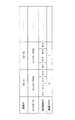
図9は、図7および図8において説明したコントローラそれぞれに割当てられる識別子と、当該識別子により指定されるコントローラと、それぞれのアレイを構成する記憶媒体に割当てられた媒体識別子との対応を示したテーブルの実施の形態を示す。図9に示されたテーブルは、例えばそれぞれのコントローラ60、62に含まれたプロセッサのメモリまたは外付けのROMといった記憶手段に保持させることができる。また、図9に示したテーブルは、例えばシステム設定の変更に容易に対応できるように、随時書換えが可能なEEPROMといった記憶手段に保持させておくこともできる。また、上述した対応テーブルは、ソフトウエア的に構成され、それぞれのプロセッサが使用することができるように構成されていてもよい。
【0055】
図9に示されるように、それぞれのコントローラは、例えば管理フラグを設定し、通常の状態では例えば管理フラグ1により、本来割り当てられた識別子を指定して転送されたデータのみを、当該識別子を付されたコントローラが管理する記憶媒体、例えばB−1からB−4に対して書込み・読出し処理する構成とされている。他のコントローラに障害が発生したことを認識した側のプロセッサは、障害発生を認識すると、図9に示される特定の実施の形態においては、識別子ID−Aを有するコントローラの管理フラグを0から1へと設定し、コントローラ62に対して識別子ID−A宛のデータについても書込アクセスを処理する構成とすることができる。また本発明においては、キャッシュ・メモリ30、46の他に予備のキャッシュ・メモリといった適切な記憶領域を設けておき、上述した障害発生の認識と同時に、プロセッサが予備のキャッシュ・メモリに対して、識別子ID−A宛転送されるデータをリカバリ・プロセスが完了するまで保持させるように指令する構成を用いることもできる
【0056】
図10は、本発明の上述したプロセスにより、スイッチング手段38を動作させ管理権を変更する場合の具体的な実施の形態を示した図である。図10に示されるように、プロセッサ26およびプロセッサ44には、スイッチング手段38を制御するための駆動手段として用いられる入出力装置64と、入出力装置66とが接続されており、それぞれスイッチング手段38を駆動することができるようにされている。上述したスイッチング手段38は、本発明の特定の実施の形態においては、それぞれのコントローラ14、16に接続される記憶媒体の、例えばドライブ・キャリアといった部分に実装することができる。
【0057】
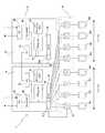
また、本発明において、スイッチング手段を実装する別の実施の形態として、上述したスイッチング手段の駆動手段をSATA上に設置することができる。図11には、SATA32、48にスイッチング手段を駆動するための駆動手段68a、68bを設け、このスイッチング手段の駆動手段から、それぞれのスイッチング手段に対して指令を行う構成とされた本発明の別の実施の形態を示す。
【0058】
図11に示した実施の形態についてさらに詳細に説明すると、例えばコントローラ14のプロセッサ26がコントローラ16の障害を検出すると、プロセッサ26は、図9に示したテーブルを使用して当該プロセッサが管理するSATA32に対し指令を発行し、障害が発生したコントローラ16が管理する記憶媒体36e〜36hを接続させるようにスイッチング手段を駆動させる。プロセッサ26は、スイッチング手段38を駆動させ、記憶媒体の管理状態を変更させることにより、コントローラの障害に際しても適切なリカバリを行うことを可能とする。
【0059】
本発明は、SATAを含むポイント−ツウ−ポイント・コントローラを使用することにより、比較的単純なスイッチング手段の使用を可能とし、効率的なコントローラのスイッチングを可能とする。また、本発明の記憶装置10は、上述した構成を採用することにより、信頼性の高い冗長性を付与することを可能とし、データ保全性を高め、コスト・パフォーマンスの高い情報記憶システムを提供することを可能とする。
【0060】
図12は、本発明において使用することがスイッチング手段38の実施の形態の詳細な構成を示した図である。図12に示されたスイッチング手段38は、本発明の特定尾実施の形態においては、上述したように、記憶媒体と、コントローラとを接続するコネクタ手段34に設けることもできるし、コントローラに含まれるSATA32、48に設けることもできる。図12においては、TX0、RX0が同一のSATAに管理されるポートを示し、TX1、RX1が他のSATAに管理されるポートを示す。正常な動作状態では、例えばTX0およびRX1がそれぞれ別のSATAへと接続されて、ポートTX、RXを介して記憶媒体に対して書込み・読取り動作を可能としている。
【0061】
本発明の特定の実施の形態についてさらに詳細に説明すると、TX0およびRX0を管理するコントローラに障害が発生した場合、プロセッサから障害発生の通知を受け取った入出力装置またはSATAに含まれるスイッチング手段の駆動手段が、セレクト信号SELおよびイネーブル信号ENを、スイッチング手段38へと発行する。セレクト信号SELとイネーブル信号ENは、スイッチング手段38に対して入力され、スイッチング手段38を駆動させて正常に動作するコントローラ側へとパスをスイッチングし、TXまたはRXを介してパスを確立させ、管理権を移転させる構成とされている。図13には、イネーブル信号ENのステータスと、セレクト信号SELのステータスと、ポートTXの接続ステータスを示す。なお、図13中、HZは、高インピーダンス状態を示す。
【0062】
図13に示されるように、例えばポートTXは、イネーブル信号ENおよびセレクト信号SELのステータスに応じてTX0、TX1にスイッチングされており、いずれかのコントローラにより制御することができることが示されている。本発明においては、図13に示されるように、本質的にはセレクト信号SELだけでもスイッチングを行うことが可能ではある。本発明においてイネーブル信号ENを重畳して使用することは、図13に示されるように、高インピーダンス状態を選択して利用することを可能とさせ、システムを駆動させたまま、例えば該当する記憶媒体を交換するなどのホット・スワップといったメンテナンスを可能とすることができる。
【0063】
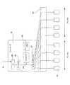
図14は、本発明の特定の実施の形態の記憶装置10の分解斜視図を示した図である。本発明の記憶装置10は、例えば、ストレージ・エリア・ネットワーク(SAN)といった情報記憶システムにおいてRAIDシステムを構成するために好適に使用することができる。図14に示した実施の形態においては、本発明の記憶装置10は、筐体70と、この筐体70に保持されたハードディスク・ドライブといった記憶媒体72と、記憶媒体72を駆動するとともに、記憶装置10に対して必要とされる電力を供給するための電源ユニット74a、74bと、それぞれの記憶媒体72から構成されるRAIDシステムなどを構成するアレイを制御するため、それぞれのアレイに対応して設けられたコントローラ76a、76bと、これらのコントローラ76a、76bのスイッチング動作を行うためのスイッチング手段を含んだコネクタ手段80とから構成されている。
【0064】
コントローラ76a、76bは、図示しないホスト・コンピュータへと接続されていて、記憶媒体72との間においてデータの転送を可能としている。また、コネクタ手段80は、本発明によりコントローラに障害がある場合には、正常なコントローラによりすべての記憶媒体72を管理させることができる構成とされている。
【0065】
図15は、本発明の記憶装置10と、ホスト・コンピュータといった情報処理手段とを接続し、情報処理装置を構成した場合に実施の形態を示した図である。図15に示された情報処理装置は、ホスト・コンピュータ82と、本発明の記憶装置84とが、例えばファイバ・チャネル・ハブ86を使用して接続されていて、ホスト・コンピュータ82と、記憶装置84とは、ホスト・コンピュータ82と記憶装置84との間でデータの相互転送を可能とする構成とされている。
【0066】
また、図15においては、ファイバ・チャネル・ハブ86をファイバ・チャネル・スイッチとして構成すれば、記憶装置84をストレージ・エリア・ネットワーク(SAN)として構成することもできる。また、図15に示されたホスト・コンピュータ82は、スタンド・アローンのコンピュータとして構成することもできるし、また、さらにイーサネット(登録商標)といったネットワークを介してクライアント・コンピュータに対して情報を提供するサーバとして構成することもできる。
【0067】
図16には、本発明の情報処理装置の別の実施の形態を示す。図16に示した実施の形態では、記憶装置84に含まれる2つのコントローラそれぞれが、ホスト・コンピュータ82a、82bに、ファイバ・チャネル・ハブ86を介して接続されていて、クラスタリングを用いた冗長方式のRAIDシステムが構成されているのが示されている。本発明では、図16に示されるように、上述したリカバリ方法を、複数のホスト・コンピュータといった情報処理手段と複数のコントローラとを使用して構築することも可能である。また、図16に示した実施の形態においては、コントローラの障害の検知は、コントローラ相互間の通信をモニタすることによっても達成することができるし、それぞれのホスト・コンピュータが、それぞれ管理するコントローラをモニタしていて、ホスト・コンピュータから障害発生時に正常なコントローラ側に指令する構成を採用することができる。
【0068】
これまで本発明を図面に示した実施の形態にもとづいて説明してきたが、本発明は図面に示した実施の形態に限定されるものではなく、スイッチング手段は、適切にアレイの切り換えを行うことができる限り、コントローラを構成する基板上に入出力装置として構成することも可能であるし、SATAを構成する基板上にモジュール化することもできるし、ハードディスク・ドライブをマウントさせるためのドライブ・キャリア上などに配置することもでき、さらにこれら以外のいかなる要素にも配置することができる。
【図面の簡単な説明】
【図1】 本発明の記憶装置の概略ブロック図。
【図2】 本発明の記憶装置の構成を示したブロック図。
【図3】 本発明の記憶装置における書込みプロセスを示したフローチャート。
【図4】 本発明の記憶装置における読出しプロセスを示したフローチャート。
【図5】 本発明においてコントローラに障害が発生した場合のスイッチングの実施の形態を示したブロック図。
【図6】 本発明における障害のリカバリ・プロセスのフローチャート。
【図7】 本発明における障害検知プロセスを示した概略図。
【図8】 本発明における別の障害検知プロセスを示した概略図。
【図9】 本発明において使用する対応テーブルの実施の形態を示した図。
【図10】 本発明のスイッチング手段を駆動するための駆動手段の構成を示したブロック図。
【図11】 本発明のスイッチング手段を駆動するための駆動手段の別の構成を示したブロック図。
【図12】 本発明のスイッチング手段の実施の形態を示した図。
【図13】 図12に示したスイッチング手段の入力ステータスと、出力ステータスとを示した図。
【図14】 本発明の記憶装置の実施の形態の分解斜視図。
【図15】 本発明の情報処理装置の実施の形態を示した図。
【図16】 本発明の情報処理装置の別の実施の形態を示した図。
【図17】 従来のパラレルATAインタフェイスを使用したRAIDシステムの構成例を示した概略図。
【図18】 従来のパラレルATAインタフェイスを使用したRAIDシステムの構成例を示した詳細図。
【符号の説明】
10…記憶装置
12…接続部
14…コントローラ
16…コントローラ
20…RAID
22…ホスト・コンピュータ
24…ファイバ・チャネル・コネクタ
26…プロセッサ
28…ファイバ・チャネル−ホスト・プロトコル変換手段
30…キャッシュ・メモリ
32…SATA
34…コネクタ手段
36…記憶媒体
38…スイッチング手段
40…ファイバ・チャネル・コネクタ
42…ファイバ・チャネル−ホスト・プロトコル変換手段
44…プロセッサ
46…キャッシュ・メモリ
48…SATA
52…ファイバ・チャネル・コネクタ
54…ファイバ・チャネル・コネクタ
56…ストレージ・アレイ・ネットワーク
58…記憶媒体
60…コントローラ
62…コントローラ
64…駆動手段(I/O)
66…駆動手段(I/O)
68a、68b…駆動手段
70…筐体
72…ハードディスク・ドライブ(記憶媒体)
74a、74b…電源
76a、76b…コントローラ
80…コネクタ手段[0001]
BACKGROUND OF THE INVENTION
The present invention relates to information storage, and more particularly, a storage device using a redundant recording system connected to an information processing means such as a computer by a serial interface, an information processing device including the storage device, and a recovery method for an information storage system About.
[0002]
[Prior art]
Until now, it has been proposed to improve data storage by providing redundancy to a storage device. Giving redundancy to a storage device in the past often uses a plurality of arrays including a plurality of storage media such as hard disks to write information to the plurality of arrays. This is done by using an information storage system such as a so-called RAID (Redundant Array of Inexpensive Disks) system.
[0003]
As for storage devices to which redundancy is given more specifically, so far (1) In order to provide redundancy to the RAID system, a plurality of controllers and storage media such as hard disk drives are used as parallel SCSI buses. Connection method using a shared bus interface, (2) Memory such as hard disk drive and multiple controllers using a dual loop interface such as Fiber Channel Arbitrated Loop A method of connecting a controller with a medium as a loop is used.
[0004]
The above-described conventionally proposed RAID system is configured on the premise that a shared bus interface is used. Specific examples of the shared bus interface described above include SCSI, fiber channel, and ATA interfaces. Of the above-described interfaces or controllers, storage media supported by SCSI or Fiber Channel are often used for applications that require high reliability such as servers. In addition, storage media supported by an interface such as ATA are often used in applications such as desktop personal computers because of the price of the interface or controller.
[0005]
FIG. 17 shows a schematic diagram when a RAID system is configured using an ATA interface known so far. As shown in FIG. 17, the
[0006]
FIG. 18 shows a more detailed block diagram of a RAID system using the conventional ATA interface shown in FIG. As shown in FIG. 18, the
[0007]
Further, as shown in FIG. 18, the
[0008]
In recent years, the ATA
[0009]
However, when the data width is increased or the frequency of the strobe signal is increased, it is difficult to synchronize data between signal lines, and interference between signal lines and noise cannot be ignored. It is known. For this reason, in the ATA interface, when using a transfer rate of Ultra DMA mode 3 (44.4 Mbyte / s) or more, for example, a 40-pin connector using an 80-core flat cable with a ground is used, and each signal line is connected. Interference is prevented.
[0010]
Furthermore, in recent years, with the increase in the speed of computer systems and the increase in the amount of data, the data transfer rate of the interface or controller has been required to be improved. For this reason, in order to introduce redundancy using the conventional ATA interface to the RAID system shown in FIGS. 17 and 18, the data transfer rate, the handling of the signal line, the reliability of the data transfer are not included. There was inconvenience in terms of sex.
[0011]
In addition, use of an information storage system with redundancy to ensure the preservation of data as the value of data increases as the speed, capacity, and network of computer systems increase. There is an increasing demand. This increases the storage capacity of the storage medium and increases the cost of the storage device in the computer system due to the addition of redundancy. In particular, in a storage device with redundancy, the interface between the storage device and the computer is increased. For a face or a controller, it is necessary to achieve higher speed and higher cost performance.
[0012]
Such a request may occur when a storage device is disconnected from the server and connected to the server via a fiber channel as an independent storage area network (SAN), or to the server via Ethernet (registered trademark). It is considered that the use of connected devices will increase. Therefore, in combination with the increase in redundancy for the storage device, the speed of the interface between the computer and the storage device and the high cost performance have been achieved so far. Therefore, there is a need for a storage device using a redundant recording method, an information processing device including the storage device, and a storage device recovery method.
[0013]
[Problems to be solved by the invention]
The present invention has been made in view of the above-mentioned problems. The present invention further improves the storage capacity and data transfer speed that are further increased, improves the reliability of the system by enhancing the data storability, and an information storage system associated therewith. It is an object of the present invention to provide a storage device using a redundant recording method, an information processing device including the storage device, and a recovery method for an information storage system, which can achieve an improvement in overall cost and performance.
[0014]
[Means for Solving the Problems]
The present invention uses a point-to-point controller (hereinafter abbreviated as a controller) for data transfer between a host computer and a recording device, thereby providing redundancy and increasing storage capacity. The idea is that it is possible to provide a storage device, an information processing device including the storage device, and a recovery method for an information storage system, which can improve data transfer speed, improve data storage performance, and improve cost performance. It is a thing. The term “point-to-point controller” used in the present invention means that only the master device is connected in the register configuration without using the master / slave distinction of the device. A controller that enables the controller and a device connected to the controller to be connected on a one-to-one basis.
[0015]
That is, the present invention uses a point-to-point controller as an interface between a host computer and a recording device. In a preferred embodiment, the controller is provided corresponding to each of the arrays constituting the RAID system. The array includes a single or a plurality of storage media, and is configured to enable so-called redundant recording. Each storage medium included in the array is connected to the point-to-point controller via the switching means, and in the normal state, one array is managed by the corresponding controller via the switching means. The other array is managed by another controller to generate a mirror copy of the array, thereby providing redundancy.
[0016]
When the controller that manages the RAID system does not function normally, in the present invention, the switching means connects the array managed by the failed controller to manage the normal controller, and the management right operates normally. It is configured to ensure the redundancy of the recording device by transferring to the controller on the side.
[0017]
That is, according to the present invention, a recording apparatus for writing / reading data to / from information processing means, the recording apparatus comprising:
A plurality of arrays each including at least one storage medium;
A plurality of point-to-point controllers that manage and communicate with each of the plurality of arrays and connect to all of the storage media;
Switching means for switching a point-to-point controller managing the array;
Means for detecting a failure of the point-to-point controller;
Means for driving the switching means in response to detection of a failure of the point-to-point controller;
The switching means is provided with a storage device that changes a management state of the array by the point-to-point controller in response to detection of the failure.
[0018]
In the storage device of the present invention, the array preferably constitutes a RAID system including a plurality of storage media. In the present invention, the means for driving the switching means specifies an identifier assigned to the point-to-point controller and a storage medium managed by the point-to-point controller corresponding to the identifier. It is possible to include a table in which medium identifiers to be associated are associated. In the storage device of the present invention, the point-to-point controller detects a failure of the point-to-point controller, and assigns a unique identifier to the point-to-point controller on the failed side. Means for obtaining and executing a predetermined process for changing the management state can be included.
[0019]
In the storage device according to the present invention, the information processing means includes means for detecting a failure of the point-to-point controller, and the point-to-point controller receives a failure from the information processing means. Means for acquiring a unique identifier of the point-to-point controller in which a failure has occurred in response to the detection notification, and executing a predetermined process for changing the management state. In the storage device of the present invention, the change in the management state of the array causes a point-to-point controller that has not failed to manage the array assigned to the point-to-point controller that has failed. be able to. In the storage device of the present invention, it is preferable that the point-to-point controller includes a serial ATA interface.
[0020]
Further, in the present invention, an information processing apparatus comprising an information processing means and a storage means for executing writing / reading of data between the information processing means,
The storage means
A plurality of arrays configured to include at least one storage medium;
A point-to-point controller that manages each of the plurality of arrays, communicates with each other, and is connectable to all of the storage media;
Switching means for switching a point-to-point controller managing the array;
Means for detecting a failure of the point-to-point controller;
Means for driving the switching means in response to detection of a failure of the point-to-point controller;
The switching means may be provided with an information processing apparatus that changes a management state of the array by the point-to-point controller in response to the detection of the failure.
[0021]
In the information processing apparatus of the present invention, it is preferable that the array constitutes a RAID system including a plurality of storage media. In the information processing apparatus according to the present invention, the means for driving the switching means is managed by the identifier assigned to the point-to-point controller and the point-to-point controller corresponding to the identifier. A table in which a medium identifier for specifying a storage medium is associated can be included. In the information processing apparatus according to the present invention, the point-to-point controller detects a failure of the point-to-point controller, and is an identifier unique to the point-to-point controller on the failure side. And a unit for executing a predetermined process for changing the management state.
[0022]
In the information processing apparatus according to the present invention, the information processing means includes means for detecting a failure of the point-to-point controller, and the point-to-point controller receives information from the information processing means. Means for acquiring a unique identifier for the point-to-point controller in which a failure has occurred in response to a failure detection notification and executing a predetermined process for changing the management state may be included. In the information processing apparatus of the present invention, the change of the management state of the array manages the array assigned to the point-to-point controller in which a failure has occurred in a point-to-point controller in which no failure has occurred. It is preferable to make it. In the information processing apparatus according to the present invention, it is preferable that the point-to-point controller includes a serial ATA interface.
[0023]
Further, according to the present invention, a plurality of arrays each including at least one storage medium are connected to each other via the switch means so as to manage the plurality of arrays, respectively, and communicate with each other. A method for recovering from a failure in an information storage system including a plurality of point-to-point controllers connectable to the storage medium
Detecting a failure of the point-to-point controller;
Operating the switching means upon detection of the fault;
Changing the management state of the array by the point-to-point controller by the switching means;
A method for recovering an information storage system is provided.
[0024]
In the recovery method of the present invention, it is preferable that the array constitutes a RAID system including a plurality of storage media, and the method recovers the array. In the recovery method of the present invention, the step of driving the switching means includes an identifier attached to the point-to-point controller and a storage medium managed by the point-to-point controller corresponding to the identifier. A step of referring to a table in which the medium identifier to be identified is associated can be included. In the recovery method of the present invention, the step of changing the management state of the array includes the step: assigning an array assigned to a point-to-point controller in which a failure has occurred to a point-to-point controller in which a failure has not occurred; It can include managing steps.
[0025]
In the recovery method of the present invention, the step of detecting a failure of the point-to-point controller and acquiring a unique identifier for the point-to-point controller on the failed side;
Performing a predetermined process for changing the management state using an identifier unique to the point-to-point controller on the failed side. In the recovery method of the present invention, the information processing means detects a failure of the point-to-point controller;
The point-to-point controller receiving a notification of failure detection from the information processing means;
Obtaining a unique identifier for the failed point-to-point controller after receiving the notification;
A step of executing a predetermined process for changing the management state using the unique identifier may be included. In the recovery method of the present invention, it is preferable that the point-to-point controller includes a serial ATA interface.
[0026]
DETAILED DESCRIPTION OF THE INVENTION
Hereinafter, the present invention will be described along specific embodiments shown in the drawings, but the present invention is not limited to the embodiments described below.
[0027]
FIG. 1 is a diagram showing a schematic configuration of a
[0028]
The array B can also be configured to include a single or a plurality of storage media. In the embodiment described with reference to FIG. 1, the array B generates a mirror copy of the array A to provide redundancy. This makes it possible to hold data with the characteristics.
[0029]
The storage medium that can be used in the present invention is not particularly limited, and any rewritable storage medium such as a hard disk, CD-R, CD-RW, DVD, or MO can be applied. In the present invention, the above-described array A and array B can also be configured as separate units including the same storage medium such as a hard disk, or units including the hard disk as a storage medium. And a unit configured separately including different storage media such as MO.
[0030]
The arrays A and B are connected to the
[0031]
More specifically, the SATA included in the
[0032]
[Table 1]
[0033]
The
[0034]
FIG. 2 shows a detailed block diagram of a portion including the controller of the
[0035]
In the particular embodiment shown in FIG. 2,
[0036]
In the
[0037]
In the
[0038]
FIG. 2 also shows that the
[0039]
Further, the
[0040]
FIG. 3 is a flowchart showing the process of the read operation when both the controllers that control the arrays A and B in the
[0041]
When the data to be read is held in the
[0042]
The
[0043]
FIG. 4 is a flowchart showing the process of the write operation when the controllers controlling the array A and the array B are both operating normally in the
[0044]
When the
[0045]
FIG. 5 shows a specific embodiment in which, in the
[0046]
FIG. 6 is a schematic flowchart of a recovery process when a controller failure occurs in the recording apparatus of the present invention. The recovery process shown in FIG. 6 monitors failures between controllers according to a predetermined method in step S30, and determines whether or not communication between processors is normal in step S31. If normal (no), the normal write / read operations shown in FIGS. 3 and 4 are executed via the controller requested by the host computer in step S32.
[0047]
If it is determined that a failure has occurred in any of the controllers (yes), the processor or cache memory on the side that has not been damaged in step S33 manages the write data to be written once. . If appropriate, write data can be managed using a buffer memory provided on the host computer side. As described in more detail below, the method for monitoring the occurrence of a failure in the controller can be determined from the communication state between the processors or the communication state between the host computer and the controller. Thereafter, in step S34, the switching means 38 is operated so that the
[0048]
Thereafter, in step S35, the write data managed by the controller on the side where no failure has occurred or the buffer memory of the host computer is accessed by a predetermined storage medium to be written. In the present invention, by adopting the above-described recovery process, the data written from the time of the failure until the time of recovery is saved, and at the time of recovery, the data is saved while providing redundancy. Make it possible to do.
[0049]
FIG. 7 shows a schematic process from the detection of the controller failure to the determination by communication between the processors until the recovery is executed. As shown in FIG. 7, the
[0050]
As described above, each of the
[0051]
The
[0052]
FIG. 8 shows a schematic process from the detection of the failure of the controller shown in FIG. 6 to the determination by communication between the
[0053]
The
[0054]
FIG. 9 is a table showing the correspondence between the identifiers assigned to the controllers described in FIG. 7 and FIG. 8, the controllers specified by the identifiers, and the medium identifiers assigned to the storage media constituting each array. An embodiment of the present invention will be described. The table shown in FIG. 9 can be held in storage means such as a processor memory or an external ROM included in each of the
[0055]
As shown in FIG. 9, each controller sets, for example, a management flag, and in the normal state, for example, only the data transferred by designating the identifier originally assigned by the
[0056]
FIG. 10 is a diagram showing a specific embodiment in which the switching means 38 is operated and the management right is changed by the above-described process of the present invention. As shown in FIG. 10, an input /
[0057]
In the present invention, as another embodiment for mounting the switching means, the above-mentioned switching means driving means can be installed on the SATA. In FIG. 11, driving means 68a and 68b for driving the switching means are provided in the
[0058]
The embodiment shown in FIG. 11 will be described in more detail. For example, when the
[0059]
The present invention allows the use of a relatively simple switching means by using a point-to-point controller including SATA, enabling efficient controller switching. Further, the
[0060]
FIG. 12 is a diagram showing a detailed configuration of an embodiment of the switching means 38 that can be used in the present invention. In the specific embodiment of the present invention, the switching means 38 shown in FIG. 12 can be provided in the connector means 34 for connecting the storage medium and the controller as described above, or is included in the controller.
[0061]
The specific embodiment of the present invention will be described in more detail. When a fault occurs in the controller that manages TX0 and RX0, the switching means included in the input / output device or SATA that has received a fault notification from the processor is described. The means issues a select signal SEL and an enable signal EN to the switching means 38. The select signal SEL and the enable signal EN are input to the switching means 38, drive the switching means 38 to switch the path to the controller side that operates normally, and establish the path via TX or RX for management. It is configured to transfer rights. FIG. 13 shows the status of the enable signal EN, the status of the select signal SEL, and the connection status of the port TX. In FIG. 13, HZ indicates a high impedance state.
[0062]
As shown in FIG. 13, for example, the port TX is switched to TX0 and TX1 according to the statuses of the enable signal EN and the select signal SEL, and can be controlled by either controller. In the present invention, as shown in FIG. 13, switching can be performed essentially by only the select signal SEL. In the present invention, the use of the enable signal EN in a superimposed manner makes it possible to select and use a high impedance state as shown in FIG. 13, and for example, a corresponding storage medium while the system is driven. It is possible to perform maintenance such as hot swapping such as replacing the battery.
[0063]
FIG. 14 is an exploded perspective view of the
[0064]
The
[0065]
FIG. 15 is a diagram showing an embodiment when the information processing apparatus is configured by connecting the
[0066]
In FIG. 15, if the
[0067]
FIG. 16 shows another embodiment of the information processing apparatus of the present invention. In the embodiment shown in FIG. 16, each of the two controllers included in the
[0068]
Although the present invention has been described based on the embodiments shown in the drawings, the present invention is not limited to the embodiments shown in the drawings, and the switching means appropriately switches the array. However, as much as possible, it can be configured as an input / output device on the board constituting the controller, or can be modularized on the board constituting the SATA, or a drive carrier for mounting the hard disk drive They can be placed on top of each other, and can be placed on any other elements.
[Brief description of the drawings]
FIG. 1 is a schematic block diagram of a storage device of the present invention.
FIG. 2 is a block diagram showing a configuration of a storage device of the present invention.
FIG. 3 is a flowchart showing a writing process in the storage device of the present invention.
FIG. 4 is a flowchart showing a reading process in the storage device of the present invention.
FIG. 5 is a block diagram showing an embodiment of switching when a failure occurs in a controller in the present invention.
FIG. 6 is a flowchart of a failure recovery process according to the present invention.
FIG. 7 is a schematic diagram showing a failure detection process in the present invention.
FIG. 8 is a schematic diagram showing another failure detection process in the present invention.
FIG. 9 is a diagram showing an embodiment of a correspondence table used in the present invention.
FIG. 10 is a block diagram showing the configuration of drive means for driving the switching means of the present invention.
FIG. 11 is a block diagram showing another configuration of the driving means for driving the switching means of the present invention.
FIG. 12 is a diagram showing an embodiment of switching means of the present invention.
13 is a diagram showing an input status and an output status of the switching means shown in FIG.
FIG. 14 is an exploded perspective view of a storage device according to an embodiment of the present invention.
FIG. 15 is a diagram showing an embodiment of an information processing apparatus according to the present invention.
FIG. 16 is a diagram showing another embodiment of the information processing apparatus of the present invention.
FIG. 17 is a schematic diagram showing a configuration example of a RAID system using a conventional parallel ATA interface.
FIG. 18 is a detailed diagram showing a configuration example of a RAID system using a conventional parallel ATA interface.
[Explanation of symbols]
10 ... Storage device
12 ... connection part
14 ... Controller
16 ... Controller
20… RAID
22: Host computer
24 ... Fiber channel connector
26. Processor
28 ... Fiber channel-host protocol conversion means
30 ... cache memory
32 ... SATA
34 ... Connector means
36 ... Storage medium
38 ... Switching means
40: Fiber channel connector
42 ... Fiber channel-host protocol conversion means
44. Processor
46: Cache memory
48 ... SATA
52 ... Fiber channel connector
54 ... Fiber channel connector
56 ... Storage array network
58 ... Storage medium
60 ... Controller
62 ... Controller
64: Driving means (I / O)
66 ... Driving means (I / O)
68a, 68b ... Driving means
70 ... Case
72. Hard disk drive (storage medium)
74a, 74b ... Power supply
76a, 76b ... Controller
80 ... Connector means
Claims (13)
Translated fromJapaneseそれぞれ少なくとも1つの記憶媒体を含んで構成される複数のアレイと、
前記複数のアレイそれぞれを管理し、相互通信するとともに、前記ポイント−ツウ−ポイント・コントローラに付された固有の識別子と、該識別子に対応するポイント−ツウ−ポイント・コントローラが管理する記憶媒体を特定する媒体識別子とを対応させたテーブルを含み、すべての前記記憶媒体に接続可能な複数のポイント−ツウ−ポイント・コントローラと、
前記アレイを管理するポイント−ツウ−ポイント・コントローラを切り換えるためのスイッチング手段と、
前記ポイント−ツウ−ポイント・コントローラの障害を検知するための手段と、
前記ポイント−ツウ−ポイント・コントローラの障害の検知に応答して前記テーブルを使用して前記スイッチング手段を駆動するための手段とを含み、
前記スイッチング手段を駆動するための手段は、前記スイッチング手段を前記障害の発生していないポイント−ツウ−ポイント・コントローラに最初から割り当てられていた固有の識別子に加え、通知を受けた前記固有の識別子に対応づけられる前記障害の発生していないポイント−ツウ−ポイント・コントローラに前記アレイのパスを切り換えて前記アレイの管理状態を変更する記憶装置。A recording device for writing / reading data to / from information processing means, the recording device comprising:
A plurality of arrays each including at least one storage medium;
Each of the plurality of arrays is managed and communicated with each other, and a unique identifier assigned to the point-to-point controller and a storage medium managed by the point-to-point controller corresponding to the identifier are specified. A plurality of point-to-point controllersincluding a table corresponding to medium identifiers to be connected and connectable to all the storage media;
Switching means for switching a point-to-point controller managing the array;
Means for detecting a failure of the point-to-point controller;
Means for driving the switching meansusing the table in response to detection of a failure of the point-to-point controller;
The means for driving the switching means includes, in addition to the unique identifier originally assigned to the non-failed point-to-point controller, the unique means that has received the notification. A storage device that changes the management state of the arrayby switching the path of the array to the point-to-point controller in which the failure does not occur .
請求項1または2に記載の記憶装置。The information processing means includes means for detecting a failure of the point-to-point controller, and theinformation processing means is a point-to-point where a failure has occurred in response to the notification of the detection of the failure. -Means for notifying the unique identifier of the controller to a non-failing point-to-point controller;
The storage device accordingto claim 1.
請求項1〜3のいずれか1項に記載の記憶装置。The point-to-point controller comprises a serial ATA interface;
Memory device according to any one of claims1-3.
前記記憶手段は、
それぞれ少なくとも1つの記憶媒体を含んで構成される複数のアレイと、
前記複数のアレイそれぞれを管理し、相互通信するとともに、前記ポイント−ツウ−ポイント・コントローラに付された固有の識別子と、該識別子に対応するポイント−ツウ−ポイント・コントローラが管理する記憶媒体を特定する媒体識別子とを対応させたテーブルを含み、すべての前記記憶媒体に接続可能な複数のポイント−ツウ−ポイント・コントローラと、
前記アレイを管理するポイント−ツウ−ポイント・コントローラを切り換えるためのスイッチング手段と、
前記ポイント−ツウ−ポイント・コントローラの障害を検知するための手段と、
前記ポイント−ツウ−ポイント・コントローラの障害の検知に応答して前記テーブルを使用して前記スイッチング手段を駆動するための手段とを含み、
前記スイッチング手段を駆動するための手段は、前記スイッチング手段を前記障害の発生していないポイント−ツウ−ポイント・コントローラに最初から割り当てられていた固有の識別子に加え、通知を受けた前記固有の識別子に対応づけられる前記障害の発生していないポイント−ツウ−ポイント・コントローラに前記アレイのパスを切り換えて前記アレイの管理状態を変更する情報処理装置。An information processing apparatus comprising information processing means and storage means for writing / reading data between the information processing means,
The storage means
A plurality of arrays each including at least one storage medium;
Each of the plurality of arrays is managed and communicated with each other, and a unique identifier assigned to the point-to-point controller and a storage medium managed by the point-to-point controller corresponding to the identifier are specified. A plurality of point-to-point controllersincluding a table corresponding to medium identifiers to be connected and connectable to all the storage media;
Switching means for switching a point-to-point controller managing the array;
Means for detecting a failure of the point-to-point controller;
Means for driving the switching meansusing the table in response to detection of a failure of the point-to-point controller;
The means for driving the switching means includes, in addition to the unique identifier originally assigned to the non-failed point-to-point controller, the unique means that has received the notification. An information processing apparatus that changes the management state of the arrayby switching the path of the array to the point-to-point controller in which the failure does not occur .
請求項5または6に記載の情報処理装置。The information processing means includes means for detecting a failure of the point-to-point controller, and theinformation processing means is a point-to-point where a failure has occurred in response to the notification of the detection of the failure. -Means for notifying the unique identifier of the controller to a non-failing point-to-point controller;
The information processing apparatus accordingto claim5 or 6 .
請求項5〜7のいずれか1項に記載の情報処理装置。Changing the management state of the array causes an unfailed point-to-point controller to manage the array assigned to the failed point-to-point controller.
The information processing apparatus according to any one of claims5 to 7 .
請求項5〜8のいずれか1項に記載の情報処理装置。The point-to-point controller comprises a serial ATA interface;
The information processing apparatus according to any one of claims5 to 8 .
前記ポイント−ツウ−ポイント・コントローラの障害を検知するステップと、
前記障害の検知に応答して通知される障害の発生した側のポイント−ツウ−ポイント・コントローラの固有の識別子を、前記ポイント−ツウ−ポイント・コントローラに付された固有の識別子と、該固有の識別子に対応するポイント−ツウ−ポイント・コントローラが管理する記憶媒体を特定する媒体識別子とを対応させたテーブルを参照するステップと、
前記障害の発生していないポイント−ツウ−ポイント・コントローラに最初から割り当てられていた固有の識別子に加え、通知を受けた前記固有の識別子に対応づけられる前記障害の発生していないポイント−ツウ−ポイント・コントローラに前記アレイのパスを切り換えて前記アレイの管理状態を変更するステップと
を含む情報記憶システムのリカバリ方法。Information processing means, a plurality of arrays each including at least one storage medium, and a plurality of arrays connected to each other via the switch means to manage the plurality of arrays, respectively communicating with each other and all the storages A method for recovering from a failure in an information storage system including a plurality of point-to-point controllers connectable to a medium, comprising:
Detecting a failure of the point-to-point controller;
The unique identifier of the failed point-to-point controller notified in response to the detection of the failureis a unique identifier assigned to the point-to-point controller, and the unique identifier Referring to a table corresponding to a medium identifier for specifying a storage medium managed by a point-to-point controller corresponding to the identifier;
Non-failure point-to-point-to-point controller in addition to the unique identifier originally assigned to the point controller, the non-failure point-to-point associated with the notified unique identifier And switching the array path to a point controller to change the management state of the array.
前記情報処理手段がポイント−ツウ−ポイント・コントローラの障害を検知して、前記情報処理手段が障害の発生した側のポイント−ツウ−ポイント・コントローラの前記固有の識別子を通知するステップを含む、
請求項10または11に記載のリカバリ方法。The step of referring to the table includes:
The information processing means detecting a failure of the point-to-point controller and theinformation processing meansnotifying the unique identifier of the point-to-point controller on the failure side;
The recovery method accordingto claim10 or 11 .
請求項10〜12のいずれか1項に記載のリカバリ方法。The point-to-point controller comprises a serial ATA interface;
The recovery method according to any one of claims10 to 12 .
Priority Applications (2)
| Application Number | Priority Date | Filing Date | Title |
|---|---|---|---|
| JP2001378580AJP3714613B2 (en) | 2001-12-12 | 2001-12-12 | Storage device, information processing device including the storage device, and information storage system recovery method |
| US10/316,618US6915381B2 (en) | 2001-12-12 | 2002-12-10 | System and method for transferring data from a secondary storage controller to a storage media after failure of a primary storage controller |
Applications Claiming Priority (1)
| Application Number | Priority Date | Filing Date | Title |
|---|---|---|---|
| JP2001378580AJP3714613B2 (en) | 2001-12-12 | 2001-12-12 | Storage device, information processing device including the storage device, and information storage system recovery method |
Publications (2)
| Publication Number | Publication Date |
|---|---|
| JP2003196036A JP2003196036A (en) | 2003-07-11 |
| JP3714613B2true JP3714613B2 (en) | 2005-11-09 |
Family
ID=19186260
Family Applications (1)
| Application Number | Title | Priority Date | Filing Date |
|---|---|---|---|
| JP2001378580AExpired - Fee RelatedJP3714613B2 (en) | 2001-12-12 | 2001-12-12 | Storage device, information processing device including the storage device, and information storage system recovery method |
Country Status (2)
| Country | Link |
|---|---|
| US (1) | US6915381B2 (en) |
| JP (1) | JP3714613B2 (en) |
Families Citing this family (76)
| Publication number | Priority date | Publication date | Assignee | Title |
|---|---|---|---|---|
| US7073022B2 (en)* | 2002-05-23 | 2006-07-04 | International Business Machines Corporation | Serial interface for a data storage array |
| JP2004021556A (en)* | 2002-06-14 | 2004-01-22 | Hitachi Ltd | Memory control device and control process thereof |
| US20040083323A1 (en)* | 2002-10-24 | 2004-04-29 | Josef Rabinovitz | Large array of SATA data device assembly for use in a peripheral storage system |
| US7167929B2 (en)* | 2003-01-13 | 2007-01-23 | Sierra Logic | Integrated-circuit implementation of a storage-shelf router and a path controller card for combined use in high-availability mass-storage-device shelves that may be incorporated within disk arrays, and a storage-shelf-interface tunneling method and system |
| US20040162926A1 (en)* | 2003-02-14 | 2004-08-19 | Itzhak Levy | Serial advanced technology attachment interface |
| US7020357B2 (en)* | 2003-04-01 | 2006-03-28 | Dell Products L.P. | Coupling device for an electronic device |
| JP4060235B2 (en) | 2003-05-22 | 2008-03-12 | 株式会社日立製作所 | Disk array device and disk array device control method |
| JP2004348464A (en)* | 2003-05-22 | 2004-12-09 | Hitachi Ltd | Storage device and communication signal shaping circuit |
| JP2005074578A (en)* | 2003-09-01 | 2005-03-24 | Sony Corp | Particle array, its manufacturing method, and magnetic recording medium |
| JP4156499B2 (en)* | 2003-11-28 | 2008-09-24 | 株式会社日立製作所 | Disk array device |
| JP4454299B2 (en)* | 2003-12-15 | 2010-04-21 | 株式会社日立製作所 | Disk array device and maintenance method of disk array device |
| JP4317436B2 (en)* | 2003-12-16 | 2009-08-19 | 株式会社日立製作所 | Disk array system and interface conversion device |
| US7111158B1 (en)* | 2003-12-24 | 2006-09-19 | Emc Corporation | Techniques for transitioning control of a serial ATA device among multiple hosts using sleep and wake commands |
| TWI256612B (en)* | 2003-12-25 | 2006-06-11 | Yung-Chau Chr | RAID system with fail over and load balance |
| JP4497918B2 (en)* | 2003-12-25 | 2010-07-07 | 株式会社日立製作所 | Storage system |
| US7209981B1 (en)* | 2004-01-09 | 2007-04-24 | Z Microsystems, Inc. | System and method for switching data storage devices and multiple processors |
| JP4634049B2 (en) | 2004-02-04 | 2011-02-16 | 株式会社日立製作所 | Error notification control in disk array system |
| JP2005222379A (en) | 2004-02-06 | 2005-08-18 | Hitachi Ltd | Disk array device and failure avoidance control method thereof |
| JP2005222429A (en)* | 2004-02-09 | 2005-08-18 | Hitachi Ltd | Management method of heterogeneous disk device in disk array device |
| GB2411258A (en)* | 2004-02-18 | 2005-08-24 | Hewlett Packard Development Co | A method of maintaining a data storage system comprising an array of storage modules |
| JP2005242555A (en)* | 2004-02-25 | 2005-09-08 | Hitachi Ltd | Storage control system and method for mounting firmware in disk-type storage device of storage control system |
| US7281153B2 (en)* | 2004-04-14 | 2007-10-09 | International Business Machines Corporation | Apparatus, system, and method for transactional peer recovery in a data sharing clustering computer system |
| US7870426B2 (en)* | 2004-04-14 | 2011-01-11 | International Business Machines Corporation | Apparatus, system, and method for transactional peer recovery in a data sharing clustering computer system |
| US7334052B2 (en)* | 2004-06-16 | 2008-02-19 | Hitachi Global Storage Technologies Netherlands B.V. | Versatile dual port connector element arrangement |
| US7523272B2 (en)* | 2004-07-12 | 2009-04-21 | Dell Products L.P. | System and method for identifying a storage drive in a storage network |
| US7350102B2 (en) | 2004-08-26 | 2008-03-25 | International Business Machine Corporation | Cost reduction schema for advanced raid algorithms |
| US7437608B2 (en)* | 2004-11-15 | 2008-10-14 | International Business Machines Corporation | Reassigning storage volumes from a failed processing system to a surviving processing system |
| JP2006146713A (en)* | 2004-11-22 | 2006-06-08 | Fujitsu Ltd | Disk array device, information processing device, data management system, command issuing method and command issuing program from target side to initiator side |
| EP2296085B1 (en) | 2004-11-30 | 2013-05-15 | Fujitsu Limited | Data storage system and capacity changing method |
| US9495263B2 (en)* | 2004-12-21 | 2016-11-15 | Infortrend Technology, Inc. | Redundant SAS storage virtualization subsystem and system using the same, and method therefor |
| CN101470587B (en)* | 2004-12-21 | 2011-08-17 | 普安科技股份有限公司 | Redundant storage virtualization subsystem |
| US8301810B2 (en) | 2004-12-21 | 2012-10-30 | Infortrend Technology, Inc. | SAS storage virtualization controller, subsystem and system using the same, and method therefor |
| US7617259B1 (en) | 2004-12-31 | 2009-11-10 | Symantec Operating Corporation | System and method for managing redundant storage consistency at a file system level |
| US7415488B1 (en) | 2004-12-31 | 2008-08-19 | Symantec Operating Corporation | System and method for redundant storage consistency recovery |
| TWI344602B (en)* | 2005-01-13 | 2011-07-01 | Infortrend Technology Inc | Redundant storage virtualization computer system |
| CN100447731C (en)* | 2005-01-13 | 2008-12-31 | 普安科技股份有限公司 | Redundant Storage Virtualization Computer System |
| JP4395766B2 (en) | 2005-03-30 | 2010-01-13 | 日本電気株式会社 | Fault analysis system, method and program |
| JP2006285808A (en)* | 2005-04-04 | 2006-10-19 | Hitachi Ltd | Storage system |
| JP2006309375A (en)* | 2005-04-27 | 2006-11-09 | Hitachi Ltd | Storage device system operating based on system information and control method of the storage device system |
| JP4969795B2 (en)* | 2005-05-12 | 2012-07-04 | 株式会社日立製作所 | Storage control system |
| US7624206B2 (en)* | 2005-09-29 | 2009-11-24 | Emc Corporation | RAID data storage system with SAS expansion |
| WO2007001728A1 (en)* | 2005-06-27 | 2007-01-04 | Emc Corporation | Raid data storage system with sas expansion |
| US7627005B2 (en) | 2005-09-29 | 2009-12-01 | Emc Corporation | Multiplexing system |
| WO2007001727A1 (en)* | 2005-06-27 | 2007-01-04 | Emc Corporation | Multiplexing system |
| US7447834B2 (en)* | 2005-06-29 | 2008-11-04 | Emc Corproation | Managing serial attached small computer systems interface communications |
| US7447833B2 (en)* | 2005-06-29 | 2008-11-04 | Emc Corporation | Techniques for providing communications in a data storage system using a single IC for both storage device communications and peer-to-peer communications |
| TWI347528B (en)* | 2005-09-23 | 2011-08-21 | Infortrend Technology Inc | Redundant storage virtualization subsystem and computer system having data path branching functionality and data-accessing method thereof |
| US7574542B2 (en)* | 2005-09-29 | 2009-08-11 | Emc Corporation | SAS expansion topology for RAID data storage including multiplexers and SAS expanders for interfacing with single or dual ports drives |
| TWI307034B (en)* | 2005-11-23 | 2009-03-01 | Infortrend Technology Inc | Storage virtualization subsystem and system with host-side redundancy via sas connectivity |
| US7574540B2 (en)* | 2006-01-03 | 2009-08-11 | Emc Corporation | Managing management controller communications |
| US7594134B1 (en)* | 2006-08-14 | 2009-09-22 | Network Appliance, Inc. | Dual access pathways to serially-connected mass data storage units |
| US8752607B2 (en) | 2007-10-22 | 2014-06-17 | Hunter Douglas Inc. | Covering for architectural openings including a rotation limiter |
| JP5353002B2 (en)* | 2007-12-28 | 2013-11-27 | 富士通株式会社 | Storage system and information processing apparatus access control method |
| US8185800B2 (en)* | 2008-01-31 | 2012-05-22 | International Business Machines Corporation | System for error control coding for memories of different types and associated methods |
| US8181094B2 (en)* | 2008-01-31 | 2012-05-15 | International Business Machines Corporation | System to improve error correction using variable latency and associated methods |
| US8171377B2 (en) | 2008-01-31 | 2012-05-01 | International Business Machines Corporation | System to improve memory reliability and associated methods |
| US8176391B2 (en)* | 2008-01-31 | 2012-05-08 | International Business Machines Corporation | System to improve miscorrection rates in error control code through buffering and associated methods |
| US8352806B2 (en)* | 2008-01-31 | 2013-01-08 | International Business Machines Corporation | System to improve memory failure management and associated methods |
| US8185801B2 (en) | 2008-01-31 | 2012-05-22 | International Business Machines Corporation | System to improve error code decoding using historical information and associated methods |
| US9128868B2 (en)* | 2008-01-31 | 2015-09-08 | International Business Machines Corporation | System for error decoding with retries and associated methods |
| WO2010068215A1 (en)* | 2008-12-11 | 2010-06-17 | Lsi Corporation | Independent drive power control |
| US8650328B1 (en)* | 2008-12-15 | 2014-02-11 | American Megatrends, Inc. | Bi-directional communication between redundant storage controllers |
| JP4893781B2 (en) | 2009-05-28 | 2012-03-07 | 富士通株式会社 | Storage control system and storage control device |
| US8375184B2 (en)* | 2009-11-30 | 2013-02-12 | Intel Corporation | Mirroring data between redundant storage controllers of a storage system |
| JP4985750B2 (en)* | 2009-12-01 | 2012-07-25 | 富士通株式会社 | Data storage system |
| US20110238909A1 (en)* | 2010-03-29 | 2011-09-29 | Pankaj Kumar | Multicasting Write Requests To Multiple Storage Controllers |
| US8812916B2 (en) | 2011-06-02 | 2014-08-19 | International Business Machines Corporation | Failure data management for a distributed computer system |
| CN102541466A (en)* | 2011-10-27 | 2012-07-04 | 忆正存储技术(武汉)有限公司 | Hybrid storage control system and method |
| CN103608762B (en)* | 2013-05-09 | 2016-03-09 | 华为技术有限公司 | Storage device, storage system and data sending method |
| JP2015169956A (en)* | 2014-03-04 | 2015-09-28 | 富士通株式会社 | Storage apparatus, information processing apparatus, cache control program, and cache control method |
| US10055279B2 (en)* | 2014-04-02 | 2018-08-21 | Hitachi, Ltd. | Semiconductor integrated circuit for communication, storage apparatus, and method for managing failure in storage apparatus |
| CN104486384A (en)* | 2014-11-28 | 2015-04-01 | 华为技术有限公司 | Storage system and exchange expansion device |
| CN106294031B (en)* | 2016-07-29 | 2019-07-12 | 杭州宏杉科技股份有限公司 | A kind of business management method and storage control |
| CN110008152A (en)* | 2019-04-10 | 2019-07-12 | 苏州浪潮智能科技有限公司 | Storage control internodal data transmission method, device, equipment and storage medium |
| TWI789627B (en) | 2020-09-09 | 2023-01-11 | 神雲科技股份有限公司 | Storage equipment and control system |
| CN112596673B (en)* | 2020-12-18 | 2023-08-18 | 南京道熵信息技术有限公司 | Multiple-active multiple-control storage system with dual RAID data protection |
Family Cites Families (7)
| Publication number | Priority date | Publication date | Assignee | Title |
|---|---|---|---|---|
| US6338110B1 (en)* | 1997-11-14 | 2002-01-08 | Sun Microsystems, Inc. | Partitioning of storage channels using programmable switches |
| JP3279248B2 (en)* | 1998-02-27 | 2002-04-30 | 日本電気株式会社 | Switch mechanism, disk array device having the same, and computer system |
| JP4294142B2 (en)* | 1999-02-02 | 2009-07-08 | 株式会社日立製作所 | Disk subsystem |
| US6370605B1 (en)* | 1999-03-04 | 2002-04-09 | Sun Microsystems, Inc. | Switch based scalable performance storage architecture |
| US6654831B1 (en)* | 2000-03-07 | 2003-11-25 | International Business Machine Corporation | Using multiple controllers together to create data spans |
| US6792486B1 (en)* | 2002-04-30 | 2004-09-14 | Western Digital Ventures, Inc. | System and method for managing information storage among plural disk drives |
| US6795850B2 (en)* | 2002-12-13 | 2004-09-21 | Sun Microsystems, Inc. | System and method for sharing memory among multiple storage device controllers |
- 2001
- 2001-12-12JPJP2001378580Apatent/JP3714613B2/ennot_activeExpired - Fee Related
- 2002
- 2002-12-10USUS10/316,618patent/US6915381B2/ennot_activeExpired - Lifetime
Also Published As
| Publication number | Publication date |
|---|---|
| US6915381B2 (en) | 2005-07-05 |
| US20030110330A1 (en) | 2003-06-12 |
| JP2003196036A (en) | 2003-07-11 |
Similar Documents
| Publication | Publication Date | Title |
|---|---|---|
| JP3714613B2 (en) | Storage device, information processing device including the storage device, and information storage system recovery method | |
| US6880101B2 (en) | System and method for providing automatic data restoration after a storage device failure | |
| JP6955466B2 (en) | SSD data replication system and method | |
| US7487285B2 (en) | Using out-of-band signaling to provide communication between storage controllers in a computer storage system | |
| US7447933B2 (en) | Fail-over storage system | |
| US7028177B2 (en) | Array controller ROM cloning in redundant controllers | |
| US7111084B2 (en) | Data storage network with host transparent failover controlled by host bus adapter | |
| US6009535A (en) | SCSI adaptor failover for a disk drive system | |
| JP4723290B2 (en) | Disk array device and control method thereof | |
| JP5511960B2 (en) | Information processing apparatus and data transfer method | |
| US20050010709A1 (en) | Application server blade for embedded storage appliance | |
| US8689044B2 (en) | SAS host controller cache tracking | |
| JP2017010390A (en) | Storage control device, storage control program, and storage control method | |
| US20070174672A1 (en) | Apparatus and method to reconfigure a storage array disposed in a data storage system | |
| US20040123027A1 (en) | Systems and methods of multiple access paths to single ported storage devices | |
| US8381027B1 (en) | Determining alternate paths in faulted systems | |
| US10915405B2 (en) | Methods for handling storage element failures to reduce storage device failure rates and devices thereof | |
| US7506201B2 (en) | System and method of repair management for RAID arrays | |
| US7752340B1 (en) | Atomic command retry in a data storage system | |
| US7743201B2 (en) | Apparatus and method to assign addresses to a plurality of information storage devices | |
| CN114691432A (en) | System and method for improving data center availability using rack-to-rack storage link cables | |
| JP4530372B2 (en) | Widespread distributed storage system | |
| JP2010033379A (en) | Virtualization system and restoration method for virtualization | |
| JP2007004297A (en) | Storage unit management device | |
| JP2008016028A (en) | Distributed storage system with wide area replication |
Legal Events
| Date | Code | Title | Description |
|---|---|---|---|
| A977 | Report on retrieval | Free format text:JAPANESE INTERMEDIATE CODE: A971007 Effective date:20050414 | |
| A131 | Notification of reasons for refusal | Free format text:JAPANESE INTERMEDIATE CODE: A131 Effective date:20050419 | |
| A521 | Written amendment | Free format text:JAPANESE INTERMEDIATE CODE: A523 Effective date:20050715 | |
| TRDD | Decision of grant or rejection written | ||
| A01 | Written decision to grant a patent or to grant a registration (utility model) | Free format text:JAPANESE INTERMEDIATE CODE: A01 Effective date:20050809 | |
| RD14 | Notification of resignation of power of sub attorney | Free format text:JAPANESE INTERMEDIATE CODE: A7434 Effective date:20050809 | |
| A61 | First payment of annual fees (during grant procedure) | Free format text:JAPANESE INTERMEDIATE CODE: A61 Effective date:20050819 | |
| R150 | Certificate of patent or registration of utility model | Free format text:JAPANESE INTERMEDIATE CODE: R150 | |
| FPAY | Renewal fee payment (event date is renewal date of database) | Free format text:PAYMENT UNTIL: 20090902 Year of fee payment:4 | |
| FPAY | Renewal fee payment (event date is renewal date of database) | Free format text:PAYMENT UNTIL: 20100902 Year of fee payment:5 | |
| FPAY | Renewal fee payment (event date is renewal date of database) | Free format text:PAYMENT UNTIL: 20110902 Year of fee payment:6 | |
| FPAY | Renewal fee payment (event date is renewal date of database) | Free format text:PAYMENT UNTIL: 20120902 Year of fee payment:7 | |
| FPAY | Renewal fee payment (event date is renewal date of database) | Free format text:PAYMENT UNTIL: 20130902 Year of fee payment:8 | |
| LAPS | Cancellation because of no payment of annual fees |