JP3713048B2 - Catheter with reinforced oval cross section - Google Patents
Catheter with reinforced oval cross sectionDownload PDFInfo
- Publication number
- JP3713048B2 JP3713048B2JP52057696AJP52057696AJP3713048B2JP 3713048 B2JP3713048 B2JP 3713048B2JP 52057696 AJP52057696 AJP 52057696AJP 52057696 AJP52057696 AJP 52057696AJP 3713048 B2JP3713048 B2JP 3713048B2
- Authority
- JP
- Japan
- Prior art keywords
- catheter shaft
- distal
- catheter
- proximal
- mandrel
- Prior art date
- Legal status (The legal status is an assumption and is not a legal conclusion. Google has not performed a legal analysis and makes no representation as to the accuracy of the status listed.)
- Expired - Lifetime
Links
Images


Classifications
- A—HUMAN NECESSITIES
- A61—MEDICAL OR VETERINARY SCIENCE; HYGIENE
- A61M—DEVICES FOR INTRODUCING MEDIA INTO, OR ONTO, THE BODY; DEVICES FOR TRANSDUCING BODY MEDIA OR FOR TAKING MEDIA FROM THE BODY; DEVICES FOR PRODUCING OR ENDING SLEEP OR STUPOR
- A61M25/00—Catheters; Hollow probes
- A61M25/10—Balloon catheters
- A61M25/104—Balloon catheters used for angioplasty
- A—HUMAN NECESSITIES
- A61—MEDICAL OR VETERINARY SCIENCE; HYGIENE
- A61M—DEVICES FOR INTRODUCING MEDIA INTO, OR ONTO, THE BODY; DEVICES FOR TRANSDUCING BODY MEDIA OR FOR TAKING MEDIA FROM THE BODY; DEVICES FOR PRODUCING OR ENDING SLEEP OR STUPOR
- A61M25/00—Catheters; Hollow probes
- A61M25/01—Introducing, guiding, advancing, emplacing or holding catheters
- A61M25/09—Guide wires
- A61M25/09016—Guide wires with mandrils
- A61M25/09033—Guide wires with mandrils with fixed mandrils, e.g. mandrils fixed to tip; Tensionable wires
- A—HUMAN NECESSITIES
- A61—MEDICAL OR VETERINARY SCIENCE; HYGIENE
- A61M—DEVICES FOR INTRODUCING MEDIA INTO, OR ONTO, THE BODY; DEVICES FOR TRANSDUCING BODY MEDIA OR FOR TAKING MEDIA FROM THE BODY; DEVICES FOR PRODUCING OR ENDING SLEEP OR STUPOR
- A61M25/00—Catheters; Hollow probes
- A61M25/0043—Catheters; Hollow probes characterised by structural features
- A61M2025/0063—Catheters; Hollow probes characterised by structural features having means, e.g. stylets, mandrils, rods or wires to reinforce or adjust temporarily the stiffness, column strength or pushability of catheters which are already inserted into the human body
Landscapes
- Health & Medical Sciences (AREA)
- Life Sciences & Earth Sciences (AREA)
- Heart & Thoracic Surgery (AREA)
- Anesthesiology (AREA)
- Biophysics (AREA)
- Pulmonology (AREA)
- Engineering & Computer Science (AREA)
- Biomedical Technology (AREA)
- Hematology (AREA)
- Animal Behavior & Ethology (AREA)
- General Health & Medical Sciences (AREA)
- Public Health (AREA)
- Veterinary Medicine (AREA)
- Child & Adolescent Psychology (AREA)
- Vascular Medicine (AREA)
- Media Introduction/Drainage Providing Device (AREA)
Description
Translated fromJapanese発明の背景
この発明は血管内カテーテル、さらに詳しくは、経皮・径ルーメン冠状動脈血管形成(PTCA)用の拡張カテーテルに関する。
PTCA手術では、予め形成された末端チップを有する案内カテーテルが、セルディンガー技術(Seldinger technique)によって患者の大腿動脈に経皮的に導入され、そして案内カテーテルの末端部が患者の上行大動脈に位置するとともに該案内カテーテルの末端チップが所望の冠状動脈の開口部に着座するまで、逆行的に前進される。案内カテーテルの基端部は患者の外側で捩じられて、該案内カテーテルの末端チップが所望の開口部に案内される。案内ワイヤが拡張カテーテルの内部ルーメン内に配置され、これら両者は案内カテーテルを通ってその末端にまで前進される。まず、案内ワイヤは、案内カテーテルの末端から患者の冠状動脈の中へ、案内ワイヤの末端が拡張されるべき障害部を横切るまで前進される。次に、末端部に膨張式バルーンを有する拡張カテーテルは、先に導入された案内ワイヤを超えて、該拡張カテーテルのバルーンが当該障害部を横切って適切に位置するまで、患者の冠状動脈の中に前進される。一旦、適切に位置決めされると、拡張バルーンは一回又はそれ以上、所定のサイズに比較的高圧に液体により膨張され、動脈流路が拡張される。一般に、バルーンの膨張径は、拡張されるルーメンの自然径と約同一であり、拡張を完結するが、障害部のいずれかの側の健康動脈を過拡張しないようになっている。バルーンが最終的に収縮すると、血流は拡張された動脈を通って回復し、拡張カテーテルはそこから取り外される。
血管形成や他の血管手術に使用される商業的に入手可能なオーバーワイヤ(over−the−wire)拡張カテーテルは、通常、末端に膨張可能な拡張部材を備えた細長い軸と、該軸の基端に設けられたアダプターとからなっている。該アダプターはカテーテル軸を通って膨張可能な拡張部材の内部に延びる内部ルーチンを介して膨張流体を供給する。
オーバーワイヤ拡張カテーテルは、一般に、カテーテル軸に押し性(pushability)を与えるための比較的硬い基端部と、曲がりくねった冠状動脈の通過を容易にする比較的フレキシブルな末端部とを有している。カテーテル軸の基端部と末端部の間の機械的性質の要求における相違は、通常、異なる材料の使用を要求するので、カテーテルの製造を複雑にする。基端部及び末端部は別個に製造され、熱又は溶融接着又は適切な粘着剤で互いに固着されるからである。カテーテル軸の基端部と末端部の間の機械的性質の要求における相違は、さらに、カテーテル軸の基端部と末端部の間の滑らかな変化を形成することの困難性を増加する。
要求されることは、押し性のために比較的硬い基端部と、患者の冠状動脈内で案内ワイヤ上の前進すなわち通過可能性(trackability)を促進するための非常にフレキシブルな末端部と、基端部と末端部の間の滑らかな遷移とを備えた製造の容易な拡張カテーテルである。本発明のカテーテルはこれら及び他の要求に答える。
発明の概要
本発明は、血管形成方法を実行するためのカテーテルに向けられており、その長さの実質的な部分にわたって長円形の横断面形状を備えた細長い軸部を有している。
長円形の横断面形状を備えたカテーテル軸の部分は、カテーテル軸の実質的な長さに沿って延びており、好ましくは少なくとも、カテーテル軸の基端部のある位置からカテーテル軸の末端部のある位置まで延びている。カテーテルは、軸の基端部から、末端に対して基部寄りで、かつ、末端軸部上の膨張可能な拡張部材と流体的に連通するカテーテル軸の末端軸部にある位置まで延びる拡張ルーメンと、軸の末端にあるポートまで延びる案内ワイヤルーメンと、を有している。カテーテル軸は、好ましくは膨張ルーメンの中に、強化又は補強マンドレルを備え、該マンドレルは長円形の横断面を有するカテーテル軸の中で延びている。マンドレルは、膨張ルーメンの中ではなく、カテーテル軸を形成する重合体材料の中に配置されてもよい。強化マンドレルは、比較的硬い基端部と、比較的フレキシブルな末端部とを有することが好ましい。マンドレルの基端部の長さは、カテーテル軸の基端部の長さよりも小さくすべきである。これにより、マンドレルの比較的硬い基端部とマンドレルの比較的フレキシブルな末端部との間の接合部は、カテーテルの基端軸部内に少なくとも部分的に配置され、カテーテル軸の基端部と末端部の間の滑らかな遷移を提供する。もし、マンドレルが完全に同一材料で形成されているなら、基端部は末端部よりも大きな横断面寸法を有するべきであり、テーパ遷移領域は基端部と末端部の間に設けられるべきである。現在好ましい実施例では、マンドレルの基端部は、その位置をカテーテルの中に固定するために、カテーテル軸の基端に装着されたアダプターに固着されている。マンドレルの末端部は自由、すなわち膨張ルーメンの中で固着されていない。また、マンドレルは膨張可能な拡張部材の基端すなわちその基部寄りに、配置されるべきである。マンドレルは、末端方向に減少する横断面を有する複数の連続部を備えていてもよく、好ましくは、そのマンドレル部間にテーパ遷移部を備えていてもよい。
カテーテル軸の長円の横断面形状を有する部分は、小横寸法よりも、約1.1から約3倍、好ましくは約1.2から約2.5倍大きな大横寸法を有する。冠状動脈に適した拡張カテーテルに対しては、大横寸法と小横寸法の間の差は少なくとも約0.003インチ(0.076mm)であり、抹消用の拡張カテーテルに対しては、その差は少なくとも約0.005インチ(0.127mm)とすべきである。カテーテル軸の横断面寸法は、さらにフレキシブルな末端軸部を与えるために、軸の長さ方向に沿って減少されてもよい。しかしながら、大横寸法と小横寸法の間に要求される差は追従されるべきである。一つの好ましい実施例では、カテーテル軸の基端部は横方向断面が楕円又は長円形状であり、末端部は僅かに卵形である。しかしながら、バルーンの基端側の位置までのカテーテル軸の全長は、全て同じ楕円形又は長円形のような卵形形状を有していてもよい。さらなる詳細と、カテーテル軸の長円横断面形状の利点とは、1994年5月27日に出願された同時継続のアメリカ特許出願番号第08/250,708号に見られる。
本発明の主要な利点は、カテーテル軸全体を統一された方法で押し出す(extrude)ことができ、これにより製造コストが著しく減少することである。強化マンドレルは非常にフレキシブルな基端部を支持するとともに、フレキシブル性を損なうことなく格別な押し性(pushability)を基端部に与える。
本発明の改良は、前述のアメリカ特許に記載されたような末端に膨張又は拡大可能な拡張部材を備えた広範囲の拡張カテーテルに適用できる。本発明のこれらの利点又は他の利点は、次の添付図面を参照してなされる以下の発明の詳細な説明からより明らかとなる。
【図面の簡単な説明】
図1は、本発明の特徴を具体化した拡張カテーテルの部分断面正面図である。
図2は、図1に示すカテーテルの2−2線断面図である。
図3は、図1に示すカテーテルの3−3線断面図である。
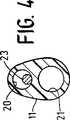
図4は、図1に示すカテーテルの4−4線断面図である。
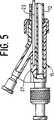
図5は、図1に示すカテーテルの基端部の部分断面正面図である。
発明の詳細な説明
図1から図5は、本発明の特徴を具体化したオーバーワイヤ型拡張カテーテル10を概略的に示す。カテーテル10は、細長いカテーテル軸11を含む。このカテーテル軸11は、基端軸部12と、該基端軸部12より小さな横寸法及び長手寸法を備えた末端軸部13と、末端軸部13に装着された拡張バルーン14と、基端軸部12の基端に装着された多アームアダプター15とを有している。拡張バルーン14は、該拡張バルーン14の内部を貫通する末端軸延長部17の末端に固着シールされた末端スカート部16を有している。拡張バルーン14の基端スカート部18は末端軸部13の外面に固着されている。基端軸部12と末端軸部13の間には、テーパが付けられた遷移軸部19が設けられている。カテーテル軸11は、膨張ルーメン20を有している。この膨張ルーメン20は、その基端部から、拡張バルーン14の内部と連通する末端軸部13のある位置まで延びている。案内ワイヤ受入れルーメン21は、カテーテル軸11内で長手方向に、平行ではあるが膨張ルーメン20から偏心して配置されている。それは、末端軸延長部17の末端の中で案内ワイヤポート22まで延びている。
強化又は補強マンドレル23は、膨張ルーメン20内に配置され、大径基端部24と、小径末端部25と、これら大径基端部24と小径末端部25の間のテーパ遷移部26とを有している。テーパ遷移部26は、基端軸部12と末端軸部13の間の滑らかな遷移をカテーテル軸11に与えるために、図示するように、基端軸部12の中に位置することが好ましい。図5に最も良く示すように、マンドレル23の基端はアダプター15の本体27の中に接着剤のような適切な手段で固着されることが好ましい。マンドレル23は拡張バルーン14の基端側の位置まで延び、その末端チップは自由、すなわち固着されていない。
図1−5に示す拡張カテーテルの使用は、オーバーワイヤ型拡張カテーテルを使用する従来のPTCA法にほぼ従う。案内ワイヤ(不図示)がカテーテル軸11の内容ルーメン21の中に差し込まれ、この案内ワイヤとカテーテル10は、患者の動脈系に予め配置されている案内カテーテル(不図示)を通って一緒に前進される。代案として、案内ワイヤはアダプター15の中央アームを介してルーメン21に導入されてもよい。案内カテーテルの末端は治療の目的とされる冠状動脈の開口部に設置され、この結果、拡張カテーテル―案内ワイヤ・アセンブリが案内カテーテルを通って前進されると、拡張カテーテルは所望の冠状動脈に直接退出する。通常、案内ワイヤは、拡張されるべき障害部を横切るまで、患者の冠状動脈に前進される。次に、拡張カテーテル10は、該拡張カテーテル10の拡張バルーン14が患者の冠状動脈の狭窄部に適切に配置されるまで、案内ワイヤ上を前進される。この結果、障害部は拡張バルーン14の膨張により拡張される。拡張後、拡張バルーン14は収縮される。次に、カテーテル10と案内ワイヤは患者から引き抜かれる。もし、さらなる治療又は診断がなされるならば、案内ワイヤは拡張カテーテルを取り外す前に交換ワイヤと置き替えることができる。これにより、第1のカテーテルを取り除き、他のカテーテルを所望の位置に前進させることができる。あるいは、延長ワイヤを案内ワイヤの基端に取り付けることができる。この延長ワイヤは患者の外方に延びて本質的に同じ機能を果たす。交換ワイヤと延長ワイヤの使用についてのさらに詳細な解説は、アメリカ特許第4,827,941号(Taylor et al.)になされている。
本発明のカテーテルと案内ワイヤの種々の構成要素は、従来の広範囲の種々の材料で形成することができる。カテーテル軸11は、ポリエチレン、ポリ塩化ビニル、ナイロン、登録商標Hytrel(DuPont社より入手可能)等のポリエステル、ポリエーテルエーテルケトン(例えば、Victrex,U.S.A.のGrade381G)等の押出し重合体材料、その他適当な重合体材料で形成してもよい。拡張バルーン14は、ポリエチレン、ポリエチレンテレフタレート、他の比較的非弾性的な重合体、その他の材料で形成してもよい。
本発明のカテーテルの寸法は、一般に、従来の血管内カテーテルの寸法に従う。冠状動脈用としては、アダプター15を除く長さは典型的には約135cmであり、カテーテル軸11の最大外径寸法は約0.02から約0.06インチ(0.51−1.52mm)である。カテーテル軸11の横断面形状は変化させることができる。例えば、一つの現在好ましい実施例では、基端軸部12は楕円形又は長円形の横断面を有していてもよい。また、末端軸部13は、マンドレル23の寸法が減少するにつれて膨張ルーメン20の寸法が減少するような僅かに卵形の横断面を有していてもよい。他の実施例では、横断面形状はカテーテル軸11の長さに沿って拡張バルーン14まで同一であってもよい。末端軸部13の横断面寸法は基端軸部12の横断面寸法より小さくてもよい。
マンドレル23の横断面寸法は、該マンドレル23を形成する材料の強度に大きく依存している。加えて、マンドレル23の横断面寸法は、該マンドレル23が膨張ルーメン20内に配置されたとき、過剰に長い膨張又は収縮時間を与える膨張ルーメン20の有効横断面を減少させないように、選択されるべきである。ステンレス鋼からなる現在予め作られたマンドレル23とともに、典型的には基端部24は約0.01から約0.015インチの径を有し、末端部25は約0.004から約0.009インチの径を有する。マンドレル23の末端部25の長さは約10から約40cm、遷移部26は約0.25から約10cm、基端部24は約80から約130cmである。典型的なマンドレル23の寸法は全長が135cmで、基端部24の長さが112.5cm、末端部25の長さが22cm、遷移部26の長さが約0.5cmであり、基端部24の径が約0.013インチ、末端部25の径が約0.007インチである。マンドレル23はステンレス鋼や、偽弾性ニッケルチタニウム合金、MP35Nのような高張力コバルト−ニッケル合金で形成されてもよい。MP35Nは、Carpenter Technology Corporationから入手可能で、コバルト約35%、ニッケル約35%、クロム約20%、モリブデン約10%、及び他の適当な材料からなる公称成分を有する。
以上、主にある好ましい実施例に関して本発明を説明したが、当業者は本発明の範囲から逸脱することなく種々の修正や改良がなされてもよいことに気が付くであろう。BACKGROUND OF THE INVENTION This invention relates to intravascular catheters and, more particularly, to dilatation catheters for percutaneous and radial lumen coronary angioplasty (PTCA).
In PTCA surgery, a guide catheter having a pre-formed distal tip is introduced percutaneously into the patient's femoral artery by the Seldinger technique, and the distal end of the guide catheter is located in the patient's ascending aorta At the same time, the distal tip of the guide catheter is advanced retrogradely until it seats in the desired coronary opening. The proximal end of the guide catheter is twisted outside the patient to guide the distal tip of the guide catheter to the desired opening. A guide wire is placed within the internal lumen of the dilatation catheter, both of which are advanced through the guide catheter to its distal end. First, the guide wire is advanced from the distal end of the guide catheter into the patient's coronary artery until the distal end of the guide wire crosses the lesion to be expanded. The dilatation catheter having an inflatable balloon at the distal end is then passed over the previously introduced guidewire until the dilatation catheter balloon is properly positioned across the lesion and into the patient's coronary artery. To be advanced. Once properly positioned, the dilatation balloon is inflated with liquid at a relatively high pressure to a predetermined size one or more times to dilate the arterial flow path. In general, the inflation diameter of the balloon is about the same as the natural diameter of the lumen to be expanded, completing the expansion, but not overexpanding the healthy artery on either side of the lesion. When the balloon is finally deflated, blood flow is restored through the dilated artery and the dilatation catheter is removed therefrom.
Commercially available over-the-wire dilatation catheters used in angioplasty and other vascular procedures typically have an elongate shaft with an expandable expansion member at the distal end and a base of the shaft. It consists of an adapter provided at the end. The adapter supplies inflation fluid through an internal routine that extends through the catheter shaft into the inflatable expansion member.
Overwire dilatation catheters generally have a relatively stiff proximal end to provide pushability to the catheter shaft and a relatively flexible distal end that facilitates the passage of tortuous coronary arteries. . Differences in mechanical property requirements between the proximal and distal ends of the catheter shaft usually complicate the manufacture of the catheter as it requires the use of different materials. This is because the proximal and distal ends are manufactured separately and secured to each other with heat or melt bonding or a suitable adhesive. The difference in mechanical property requirements between the proximal and distal ends of the catheter shaft further increases the difficulty of creating a smooth change between the proximal and distal ends of the catheter shaft.
What is required is a relatively stiff proximal end for pushability and a very flexible distal end to facilitate advancement or trackability over the guidewire within the patient's coronary artery; An easily manufactured dilatation catheter with a smooth transition between the proximal and distal ends. The catheter of the present invention answers these and other needs.
SUMMARY OF THE INVENTION The present invention is directed to a catheter for performing an angioplasty method and has an elongate shaft with an oval cross-sectional shape over a substantial portion of its length.
The portion of the catheter shaft with an oval cross-sectional shape extends along the substantial length of the catheter shaft, preferably at least from a location at the proximal end of the catheter shaft to the distal end of the catheter shaft. It extends to a certain position. An expansion lumen extending from a proximal end of the shaft to a position proximal to the distal end and in a distal shaft portion of the catheter shaft that is in fluid communication with an inflatable expansion member on the distal shaft; A guide wire lumen extending to a port at the end of the shaft. The catheter shaft preferably comprises a reinforcing or reinforcing mandrel in the inflation lumen, the mandrel extending within the catheter shaft having an oval cross section. The mandrel may be placed in the polymeric material that forms the catheter shaft rather than in the inflation lumen. The reinforced mandrel preferably has a relatively hard proximal end and a relatively flexible distal end. The length of the proximal end of the mandrel should be less than the length of the proximal end of the catheter shaft. Thereby, the joint between the relatively hard proximal end of the mandrel and the relatively flexible distal end of the mandrel is at least partially disposed within the proximal shaft of the catheter, and the proximal and distal ends of the catheter shaft Provides a smooth transition between parts. If the mandrel is made entirely of the same material, the proximal end should have a larger cross-sectional dimension than the distal end and a tapered transition region should be provided between the proximal and distal ends. is there. In the presently preferred embodiment, the proximal end of the mandrel is secured to an adapter attached to the proximal end of the catheter shaft to secure its position within the catheter. The end of the mandrel is free, i.e. not secured in the inflation lumen. Also, the mandrel should be placed at the proximal end of the inflatable expansion member, i.e. near its base. The mandrel may include a plurality of continuous portions having a cross-section that decreases in the distal direction, and may preferably include a tapered transition between the mandrels.
The portion of the catheter shaft having the oval cross-sectional shape has a large lateral dimension that is about 1.1 to about 3 times, preferably about 1.2 to about 2.5 times larger than the small lateral dimension. For dilatation catheters suitable for coronary arteries, the difference between the large and small transverse dimensions is at least about 0.003 inches (0.076 mm), and for a dilatation dilatation catheter, the difference Should be at least about 0.005 inch (0.127 mm). The cross-sectional dimension of the catheter shaft may be reduced along the length of the shaft to provide a more flexible distal shaft. However, the required difference between the large and small lateral dimensions should be followed. In one preferred embodiment, the proximal end of the catheter shaft is oval or oval in cross section and the distal end is slightly oval. However, the entire length of the catheter shaft up to the position on the proximal side of the balloon may have an oval shape such as the same oval or oval shape. Further details and advantages of the oval cross-sectional shape of the catheter shaft can be found in co-pending US patent application Ser. No. 08 / 250,708, filed May 27,1994.
A major advantage of the present invention is that the entire catheter shaft can be extruded in a unified manner, thereby significantly reducing manufacturing costs. The reinforced mandrel supports a very flexible proximal end and provides exceptional pushability to the proximal end without compromising flexibility.
The improvements of the present invention can be applied to a wide range of dilatation catheters having a dilation member that can be inflated or expanded at the end as described in the aforementioned US patent. These and other advantages of the present invention will become more apparent from the following detailed description of the invention made with reference to the accompanying drawings.
[Brief description of the drawings]
FIG. 1 is a partial cross-sectional front view of a dilatation catheter embodying features of the present invention.
2 is a cross-sectional view of the catheter shown in FIG. 1 taken along line 2-2.
3 is a cross-sectional view of the catheter shown in FIG. 1 taken along line 3-3.
4 is a cross-sectional view of the catheter shown in FIG. 1 taken along line 4-4.
FIG. 5 is a partial cross-sectional front view of the proximal end portion of the catheter shown in FIG. 1.
DETAILED DESCRIPTION OF THE INVENTION FIGS. 1-5 schematically illustrate an
A reinforced or reinforced
The use of the dilatation catheter shown in FIGS. 1-5 approximately follows the conventional PTCA method using an overwire dilatation catheter. Guidewire(not shown) is inserted into the
The various components of the catheter and guidewire of the present invention can be formed from a wide variety of conventional materials. The
The dimensions of the catheter of the present invention generally follow those of conventional intravascular catheters. For coronary arteries, the length excluding the
The cross-sectional dimension of the
Although the invention has been described primarily with reference to certain preferred embodiments, those skilled in the art will recognize that various modifications and improvements may be made without departing from the scope of the invention.
Claims (15)
Translated fromJapanesea)基端部と、末端部と、比較的硬い基端カテーテル軸部と、該比較的硬い基端カテーテル軸部よりもフレキシブルである比較的フレキシブルな末端カテーテル軸部と、前記末端部に位置する案内ワイヤポートと、前記案内ワイヤポートへ延びる案内ワイヤ受入れ内部ルーメンと、該案内ワイヤ受入れ内部ルーメンから偏心しかつ平行で、前記末端部の基端寄りの位置まで延びる膨張ルーメンと、その長さの実質部分に沿って長円形の横断面とを有し、前記膨張ルーメンと前記案内ワイヤ受入れ内部ルーメンとともに重合体材料の単一押出しにより形成された細長いカテーテル軸と、
b)前記膨張ルーメンと流体で連通する内部を有し、前記カテーテル軸の末端部寄りの前記末端カテーテル軸部に装着された膨張可能な拡張部材と、
ここで、前記ガイドワイヤ受け入れ内部ルーメンの少なくとも一部は、前記膨張可能な拡張部材の内面から延びており、
c)比較的硬い基端部と該比較的硬い基端部よりフレキシブルである比較的フレキシブルな末端部とを有し、前記膨張ルーメン内に配置されて前記基端カテーテル軸部と前記末端カテーテル軸部内で延びており、前記膨張可能な拡張部材の末端スカート部の基端側に配置された末端チップを備えるとともに、前記基端カテーテル軸部の中に前記比較的フレキシブルな末端部の少なくとも一部分を備えた細長いマンドレルと、からなる拡張カテーテル。In a dilatation catheter for performing an angioplasty method,
a) a proximal end, a distal end, and a relatively stiff proximal catheter shaft, and the relatively flexible distal catheter shaftis more flexible than the relatively hard proximal catheter shaft, located inthe distal portion guide wire port, a guide wire receiving inner lumen extending tothe guidewire port, eccentric from the guide wire-receiving inner lumen and parallel, the inflation lumen extending to a position proximally ofsaid distal end,a length of and aalong a substantial portion oblong cross-section of an elongated catheter shaft formed by a single extrusion ofthe polymer material with the inflation lumen andthe guide wire receiving inner lumen,
b) has an interior communicating withsaid inflation lumen fluid, an inflatable expander member attached tosaid distal catheter shaft section of the distalend side of thesaid catheter shaft,
Wherein atleast a portion of said guide wire receiving inner lumen extends from the inner surface ofthe expandable dilation member,
c) and a relatively flexible distal portionwhich is relatively hard base end portion andsaid relatively rigid flexible than the proximal portion,thesaid proximal catheter shaft portionis disposed within the inflation lumen distal catheter shaftextends in a partprovided with asaid inflatable extensiondistal skirt distaltip disposed proximally of the member, at least a portion ofthe relatively flexible distal portion insaid proximal catheter shaft section And an elongated mandrel with a dilatation catheter.
前記マンドレルは、該マンドレルの長手方向位置を前記膨張ルーメン内で固定するため、前記アダプター内に固着された基端部を有していることを特徴とする請求項3に記載の拡張カテーテル。The catheter has an adapter attached to the proximal end of the catheter shaft;
4. The dilatation catheter according to claim 3, wherein the mandrel has a proximal end secured within the adapter for securing the longitudinal position of the mandrel within the inflation lumen.
a)基端部と、末端部と、比較的硬い基端カテーテル軸部と、該比較的硬い基端カテーテル軸部よりもフレキシブルであって、前記比較的硬い基端カテーテル軸部の横寸法よりも小さな少なくとも1つの横寸法を有する比較的フレキシブルな末端カテーテル軸部と、前記末端部に位置する案内ワイヤポートと、前記案内ワイヤポートへ延びる案内ワイヤ受入れ内部ルーメンと、該案内ワイヤ受入れ内部ルーメンから偏心しかつ平行で、前記末端部の基端寄りの位置まで延びる膨張ルーメンと、その長さの実質部分に沿って長円形の横断面とを有し、前記膨張ルーメンと前記案内ワイヤ受入れ内部ルーメンとともに重合体材料の単一押出しにより形成された細長いカテーテル軸と、a) a proximal end portion, a distal end portion, a relatively hard proximal catheter shaft portion, more flexible than the relatively hard proximal catheter shaft portion, and from a lateral dimension of the relatively hard proximal catheter shaft portion; A relatively flexible distal catheter shaft having at least one lateral dimension, a guide wire port located at the distal end, a guide wire receiving inner lumen extending to the guide wire port, and the guide wire receiving inner lumen An inflation lumen that is eccentric and parallel and extends to a position near the proximal end of the distal end, and an oblong cross section along a substantial portion of the length, the inflation lumen and the guide wire receiving inner lumen An elongated catheter shaft formed by a single extrusion of the polymeric material with
b)前記膨張ルーメンと流体で連通する内部を有し、前記カテーテル軸の末端部寄りの前記末端カテーテル軸部に装着された膨張可能な拡張部材と、b) an inflatable expansion member having an interior in fluid communication with the inflation lumen and attached to the distal catheter shaft near the distal end of the catheter shaft;
ここで、前記ガイドワイヤ受け入れ内部ルーメンの少なくとも一部は、前記膨張可能な拡張部材の内面から延びており、Wherein at least a portion of the guidewire receiving inner lumen extends from an inner surface of the inflatable expansion member;
c)比較的硬い基端部と該比較的硬い基端部よりフレキシブルである比較的フレキシブルな末端部とを有し、前記膨張ルーメン内に配置されて前記基端カテーテル軸部と前記末端カテーテル軸部内で延びており、前記膨張可能な拡張部材の末端スカート部の基端側に配置された末端チップを備えるとともに、前記基端カテーテル軸部の中に前記比較的フレキシブルな末端部の少なくとも一部分を備えた細長いマンドレルと、からなる拡張カテーテル。c) having a relatively stiff proximal end and a relatively flexible distal end that is more flexible than the relatively stiff proximal end and disposed within the inflation lumen to provide the proximal catheter shaft and the distal catheter shaft And a distal tip disposed proximally of the distal skirt portion of the inflatable expansion member and having at least a portion of the relatively flexible distal portion in the proximal catheter shaft. An expansion catheter comprising an elongated mandrel.
Applications Claiming Priority (3)
| Application Number | Priority Date | Filing Date | Title |
|---|---|---|---|
| US36460894A | 1994-12-27 | 1994-12-27 | |
| US08/364,608 | 1994-12-27 | ||
| PCT/US1995/016862WO1996020025A1 (en) | 1994-12-27 | 1995-12-21 | Catheter with reinforced oblong transverse cross section |
Publications (2)
| Publication Number | Publication Date |
|---|---|
| JPH10511295A JPH10511295A (en) | 1998-11-04 |
| JP3713048B2true JP3713048B2 (en) | 2005-11-02 |
Family
ID=23435285
Family Applications (1)
| Application Number | Title | Priority Date | Filing Date |
|---|---|---|---|
| JP52057696AExpired - LifetimeJP3713048B2 (en) | 1994-12-27 | 1995-12-21 | Catheter with reinforced oval cross section |
Country Status (6)
| Country | Link |
|---|---|
| US (1) | US5868706A (en) |
| EP (1) | EP0850084B1 (en) |
| JP (1) | JP3713048B2 (en) |
| CA (1) | CA2208795A1 (en) |
| DE (1) | DE69534065T2 (en) |
| WO (1) | WO1996020025A1 (en) |
Families Citing this family (50)
| Publication number | Priority date | Publication date | Assignee | Title |
|---|---|---|---|---|
| JP2000503234A (en)* | 1996-01-16 | 2000-03-21 | アドバンスト・カーディオバスキュラー・システムズ・インコーポレイテッド | Smooth and easy to connect catheter shaft |
| US6217547B1 (en)* | 1996-01-16 | 2001-04-17 | Advanced Cardiovascular Systems, Inc. | Lubricous and readily bondable catheter shaft |
| US20050245894A1 (en)* | 1996-05-20 | 2005-11-03 | Medtronic Vascular, Inc. | Methods and apparatuses for drug delivery to an intravascular occlusion |
| US6270477B1 (en)* | 1996-05-20 | 2001-08-07 | Percusurge, Inc. | Catheter for emboli containment |
| US6652480B1 (en) | 1997-03-06 | 2003-11-25 | Medtronic Ave., Inc. | Methods for reducing distal embolization |
| US6544276B1 (en)* | 1996-05-20 | 2003-04-08 | Medtronic Ave. Inc. | Exchange method for emboli containment |
| US6312374B1 (en) | 1997-03-06 | 2001-11-06 | Progenix, Llc | Radioactive wire placement catheter |
| ATE286760T1 (en)* | 1997-09-23 | 2005-01-15 | United States Surgical Corp | CATHETER WITH SAFETY DISTANCE STRUCTURE |
| JP2000107293A (en)* | 1998-10-08 | 2000-04-18 | Terumo Corp | Vasodilating instrument |
| US6283947B1 (en)* | 1999-07-13 | 2001-09-04 | Advanced Cardiovascular Systems, Inc. | Local drug delivery injection catheter |
| US6494862B1 (en) | 1999-07-13 | 2002-12-17 | Advanced Cardiovascular Systems, Inc. | Substance delivery apparatus and a method of delivering a therapeutic substance to an anatomical passageway |
| US6589207B1 (en) | 1999-12-21 | 2003-07-08 | Advanced Cardiovascular Systems, Inc. | Rapid exchange catheter having a support mandrel |
| US7118551B1 (en) | 1999-12-22 | 2006-10-10 | Advanced Cardiovascular Systems, Inc. | Non-metal reinforcing mandrel |
| US6733486B1 (en)* | 1999-12-22 | 2004-05-11 | Advanced Cardiovascular Systems, Inc. | Catheter having a reinforcing mandrel |
| WO2001082814A2 (en)* | 2000-05-03 | 2001-11-08 | C.R. Bard, Inc. | Apparatus and methods for mapping and ablation in electrophysiology procedures |
| US6544218B1 (en)* | 2000-07-26 | 2003-04-08 | Advanced Cardiovascular Systems, Inc. | Catheter with biased shaft |
| US7255695B2 (en)* | 2001-04-27 | 2007-08-14 | C.R. Bard, Inc. | Systems and methods for three-dimensional mapping of electrical activity |
| US7422579B2 (en) | 2001-05-01 | 2008-09-09 | St. Jude Medical Cardiology Divison, Inc. | Emboli protection devices and related methods of use |
| US7374560B2 (en)* | 2001-05-01 | 2008-05-20 | St. Jude Medical, Cardiology Division, Inc. | Emboli protection devices and related methods of use |
| US7604612B2 (en)* | 2001-05-01 | 2009-10-20 | St. Jude Medical, Cardiology Division, Inc. | Emboli protection devices and related methods of use |
| US7727229B2 (en) | 2001-05-01 | 2010-06-01 | C.R. Bard, Inc. | Method and apparatus for altering conduction properties in the heart and in adjacent vessels |
| US6716223B2 (en) | 2001-11-09 | 2004-04-06 | Micrus Corporation | Reloadable sheath for catheter system for deploying vasoocclusive devices |
| US10258340B2 (en)* | 2001-11-09 | 2019-04-16 | DePuy Synthes Products, Inc. | Reloadable sheath for catheter system for deploying vasoocclusive devices |
| US6800065B2 (en) | 2002-04-04 | 2004-10-05 | Medtronic Ave, Inc. | Catheter and guide wire exchange system |
| US6837870B2 (en)* | 2002-07-23 | 2005-01-04 | Advanced Cardiovascular Systems, Inc. | Catheter having a multilayered shaft section with a reinforcing mandrel |
| US7331933B2 (en)* | 2002-12-31 | 2008-02-19 | Advanced Cardiovascular Systems, Inc. | Balloon catheter with a compression member for balloon bonding |
| ES2325398T3 (en) | 2003-02-26 | 2009-09-03 | Boston Scientific Limited | BALL CATETER. |
| US7175607B2 (en)* | 2003-03-06 | 2007-02-13 | Advanced Cardiovascular Systems, Inc. | Catheter balloon liner with variable thickness and method for making same |
| DE602004011608T2 (en)* | 2003-03-28 | 2009-01-29 | C.R. Bard, Inc. | Catheter with braided mesh |
| US20040260329A1 (en)* | 2003-06-19 | 2004-12-23 | Richard Gribbons | Catheter and guide wire exchange system with decoupled guide member |
| US20050182386A1 (en)* | 2004-02-17 | 2005-08-18 | Steen Aggerholm | Catheter with stiffening element |
| US7468051B2 (en)* | 2004-03-02 | 2008-12-23 | Boston Scientific Scimed, Inc. | Occlusion balloon catheter with external inflation lumen |
| US8249685B2 (en)* | 2004-05-17 | 2012-08-21 | C.R. Bard, Inc. | Method and apparatus for mapping and/or ablation of cardiac tissue |
| US7699862B2 (en)* | 2005-01-25 | 2010-04-20 | Micrus Corporation | Resheathing tool |
| US20060258987A1 (en)* | 2005-05-10 | 2006-11-16 | Cook Incorporated | Catheter stiffening member |
| US8221348B2 (en)* | 2005-07-07 | 2012-07-17 | St. Jude Medical, Cardiology Division, Inc. | Embolic protection device and methods of use |
| US20090054874A1 (en)* | 2007-08-23 | 2009-02-26 | C. R. Bard, Inc. | Multi-lumen catheter including a lumen having a variable cross sectional area |
| US8007490B2 (en)* | 2007-10-19 | 2011-08-30 | Cook Medical Technologies Llc | Reduced width dual-lumen catheter |
| JP5906239B2 (en) | 2010-07-15 | 2016-04-20 | セント・ジュード・メディカル,インコーポレイテッド | Retainer for transcatheter heart valve delivery system |
| US10130470B2 (en) | 2010-08-17 | 2018-11-20 | St. Jude Medical, Llc | Sleeve for facilitating movement of a transfemoral catheter |
| JP2013540481A (en) | 2010-09-17 | 2013-11-07 | セント・ジュード・メディカル,カーディオロジー・ディヴィジョン,インコーポレイテッド | Retainer for transcatheter heart valve delivery system |
| US9186129B2 (en)* | 2011-05-26 | 2015-11-17 | Adn International, Llc | Expandable device for tissue collection from an aerodigestive body lumen |
| EP2736450A1 (en) | 2011-07-28 | 2014-06-04 | St. Jude Medical, Inc. | Expandable radiopaque marker for transcatheter aortic valve implantation |
| US9480561B2 (en)* | 2012-06-26 | 2016-11-01 | St. Jude Medical, Cardiology Division, Inc. | Apparatus and method for aortic protection and TAVI planar alignment |
| US9918837B2 (en) | 2012-06-29 | 2018-03-20 | St. Jude Medical, Cardiology Division, Inc. | System to assist in the release of a collapsible stent from a delivery device |
| US9072864B2 (en)* | 2012-11-28 | 2015-07-07 | Ad-Tech Medical Instrument Corporation | Catheter with depth electrode for dual-purpose use |
| US9687373B2 (en)* | 2012-12-21 | 2017-06-27 | Cook Medical Technologies Llc | Systems and methods for securing and releasing a portion of a stent |
| EP3043755B1 (en) | 2013-09-12 | 2022-10-19 | St. Jude Medical, Cardiology Division, Inc. | Atraumatic interface in an implant delivery device |
| US10080865B2 (en) | 2014-01-14 | 2018-09-25 | Cook Medical Technologies Llc | Multi-lumen catheters for small body vessel applications |
| US10667907B2 (en) | 2016-05-13 | 2020-06-02 | St. Jude Medical, Cardiology Division, Inc. | Systems and methods for device implantation |
Family Cites Families (63)
| Publication number | Priority date | Publication date | Assignee | Title |
|---|---|---|---|---|
| US2248934A (en)* | 1937-12-24 | 1941-07-15 | Davol Rubber Co | Inflatable catheter |
| US2457244A (en)* | 1943-06-22 | 1948-12-28 | Otis F Lamson | Medical appliance for control of enemata |
| US2912981A (en)* | 1958-04-10 | 1959-11-17 | Frank J Keough | Inflatable retention catheter |
| US2930377A (en)* | 1958-06-02 | 1960-03-29 | Baxter Don Inc | Surgical tube |
| US3112478A (en)* | 1959-01-07 | 1963-11-26 | Lab For Electronics Inc | Frequency responsive apparatus |
| US3112748A (en)* | 1960-04-04 | 1963-12-03 | Pharmaseal Lab | Surgical tube |
| US3769981A (en)* | 1972-02-09 | 1973-11-06 | Kendall & Co | Urinary catheter |
| US3978863A (en)* | 1974-06-06 | 1976-09-07 | Bruce E. Fettel | Expanding tip embolectomy catheter with indicator balloon |
| US3983879A (en)* | 1974-07-25 | 1976-10-05 | Western Acadia, Incorporated | Silicone catheter |
| US4458677A (en)* | 1979-09-19 | 1984-07-10 | Mccorkle Jr Charles E | Intravenous channel cardiac electrode and lead assembly and method |
| US4295464A (en)* | 1980-03-21 | 1981-10-20 | Shihata Alfred A | Ureteric stone extractor with two ballooned catheters |
| US4406656A (en)* | 1981-06-01 | 1983-09-27 | Brack Gillium Hattler | Venous catheter having collapsible multi-lumens |
| CA1186192A (en)* | 1982-01-27 | 1985-04-30 | David S. Hickey | Urethral catheter |
| US4484579A (en)* | 1982-07-19 | 1984-11-27 | University Of Pittsburgh | Commissurotomy catheter apparatus and method |
| DE3228438C2 (en)* | 1982-07-30 | 1985-01-17 | Karl Dr. 6301 Pohlheim Aigner | Double lumen catheter |
| US4651721A (en)* | 1985-04-10 | 1987-03-24 | American Medical Systems, Inc. | Penile prosthesis system |
| US5102390A (en)* | 1985-05-02 | 1992-04-07 | C. R. Bard, Inc. | Microdilatation probe and system for performing angioplasty in highly stenosed blood vessels |
| US4601713A (en)* | 1985-06-11 | 1986-07-22 | Genus Catheter Technologies, Inc. | Variable diameter catheter |
| DE3522782A1 (en)* | 1985-06-26 | 1987-01-15 | Peter Brehm Chir Mechanik Werk | Double-lumen follicle-biopsy cannula |
| US5040548A (en)* | 1989-06-01 | 1991-08-20 | Yock Paul G | Angioplasty mehtod |
| AT385890B (en)* | 1987-04-13 | 1988-05-25 | Immuno Ag | BIOPSY DEVICE FOR OBTAINING TEST SAMPLES AND APPLICATION OF SUBSTANCES IN ONE WORKPROCESS |
| US4723936A (en)* | 1986-07-22 | 1988-02-09 | Versaflex Delivery Systems Inc. | Steerable catheter |
| US4790315A (en)* | 1986-09-02 | 1988-12-13 | Advanced Cardiovascular Systems, Inc. | Perfusion dilatation catheter and method of manufacture |
| US4776841A (en)* | 1986-09-11 | 1988-10-11 | Catalano Marc L | Bilumen peripheral venous catheter with adapter |
| US4782834A (en)* | 1987-01-06 | 1988-11-08 | Advanced Cardiovascular Systems, Inc. | Dual lumen dilatation catheter and method of manufacturing the same |
| US4748982A (en)* | 1987-01-06 | 1988-06-07 | Advanced Cardiovascular Systems, Inc. | Reinforced balloon dilatation catheter with slitted exchange sleeve and method |
| US4771777A (en)* | 1987-01-06 | 1988-09-20 | Advanced Cardiovascular Systems, Inc. | Perfusion type balloon dilatation catheter, apparatus and method |
| US4906230A (en)* | 1987-06-30 | 1990-03-06 | Baxter Travenol Laboratories, Inc. | Steerable catheter tip |
| US4892519A (en)* | 1987-12-03 | 1990-01-09 | Advanced Cardiovascular Systems, Inc. | Steerable perfusion dilatation catheter |
| DE3742710A1 (en)* | 1987-12-16 | 1989-07-06 | Lang Volker | Transurethral bladder catheter which cleans the mucous membranes |
| US5425711A (en)* | 1988-02-29 | 1995-06-20 | Scimed Life Systems, Inc. | Intravascular catheter with distal guide wire lumen and transition member |
| US4944745A (en)* | 1988-02-29 | 1990-07-31 | Scimed Life Systems, Inc. | Perfusion balloon catheter |
| US4943278A (en)* | 1988-02-29 | 1990-07-24 | Scimed Life Systems, Inc. | Dilatation balloon catheter |
| US5156594A (en)* | 1990-08-28 | 1992-10-20 | Scimed Life Systems, Inc. | Balloon catheter with distal guide wire lumen |
| US5171222A (en)* | 1988-03-10 | 1992-12-15 | Scimed Life Systems, Inc. | Interlocking peel-away dilation catheter |
| US4877031A (en)* | 1988-07-22 | 1989-10-31 | Advanced Cardiovascular Systems, Inc. | Steerable perfusion dilatation catheter |
| US4998923A (en)* | 1988-08-11 | 1991-03-12 | Advanced Cardiovascular Systems, Inc. | Steerable dilatation catheter |
| US5071425A (en)* | 1988-09-12 | 1991-12-10 | Devices For Vascular Intervention, Inc. | Atherectomy catheter and method of forming the same |
| US4973278A (en)* | 1988-09-20 | 1990-11-27 | Williams Thomas R | Floatable portable seat and method for use |
| US4917666A (en)* | 1988-11-14 | 1990-04-17 | Medtronic Versaflex, Inc. | Steerable thru-lumen catheter |
| CA1329090C (en)* | 1989-01-30 | 1994-05-03 | Geoffrey S. Martin | Angioplasty catheter |
| CA1329091C (en)* | 1989-01-31 | 1994-05-03 | Geoffrey S. Martin | Catheter with balloon retainer |
| US5046503A (en)* | 1989-04-26 | 1991-09-10 | Advanced Cardiovascular Systems, Inc. | Angioplasty autoperfusion catheter flow measurement method and apparatus |
| US5217440A (en)* | 1989-10-06 | 1993-06-08 | C. R. Bard, Inc. | Multilaminate coiled film catheter construction |
| US5037386A (en)* | 1989-11-17 | 1991-08-06 | Minnesota Mining And Manufacturing Company | Pressure sensing scope cannula |
| US5176637A (en)* | 1990-04-19 | 1993-01-05 | Terumo Kabushiki Kaisha | Catheter equipped with a dilation element |
| US5106368A (en)* | 1990-04-20 | 1992-04-21 | Cook Incorporated | Collapsible lumen catheter for extracorporeal treatment |
| US5149330A (en)* | 1991-01-10 | 1992-09-22 | The Kendall Company | Catheter convertible from single to multilumen |
| CA2060067A1 (en)* | 1991-01-28 | 1992-07-29 | Lilip Lau | Stent delivery system |
| US5219335A (en)* | 1991-05-23 | 1993-06-15 | Scimed Life Systems, Inc. | Intravascular device such as introducer sheath or balloon catheter or the like and methods for use thereof |
| US5154725A (en)* | 1991-06-07 | 1992-10-13 | Advanced Cardiovascular Systems, Inc. | Easily exchangeable catheter system |
| US5135535A (en)* | 1991-06-11 | 1992-08-04 | Advanced Cardiovascular Systems, Inc. | Catheter system with catheter and guidewire exchange |
| US5242396A (en)* | 1991-12-19 | 1993-09-07 | Advanced Cardiovascular Systems, Inc. | Dilatation catheter with reinforcing mandrel |
| CA2060133C (en)* | 1992-01-30 | 2002-05-28 | Geoffrey S. Martin | Balloon catheter |
| US5195971A (en)* | 1992-02-10 | 1993-03-23 | Advanced Cardiovascular Systems, Inc. | Perfusion type dilatation catheter |
| JPH11221286A (en)* | 1992-03-19 | 1999-08-17 | Keiji Igaki | Medical tube |
| US5300025A (en)* | 1992-09-30 | 1994-04-05 | Advanced Cardiovascular Systems, Inc. | Dilatation catheter having a coil supported inflation lumen |
| US5531690A (en)* | 1992-10-30 | 1996-07-02 | Cordis Corporation | Rapid exchange catheter |
| US5549556A (en)* | 1992-11-19 | 1996-08-27 | Medtronic, Inc. | Rapid exchange catheter with external wire lumen |
| WO1994021320A1 (en)* | 1993-03-15 | 1994-09-29 | Advanced Cardiovascular Systems, Inc. | Fluid delivery catheter |
| US5545138A (en)* | 1994-02-28 | 1996-08-13 | Medtronic, Inc. | Adjustable stiffness dilatation catheter |
| FR2718645B1 (en)* | 1994-04-15 | 1996-07-12 | Nycomed Lab Sa | Rapid exchange dilation catheter. |
| US5470315A (en)* | 1994-09-20 | 1995-11-28 | Scimed Life Systems, Inc. | Over-the-wire type balloon catheter with proximal hypotube |
- 1995
- 1995-12-21EPEP95943976Apatent/EP0850084B1/ennot_activeExpired - Lifetime
- 1995-12-21WOPCT/US1995/016862patent/WO1996020025A1/enactiveIP Right Grant
- 1995-12-21DEDE69534065Tpatent/DE69534065T2/ennot_activeExpired - Lifetime
- 1995-12-21CACA002208795Apatent/CA2208795A1/ennot_activeAbandoned
- 1995-12-21JPJP52057696Apatent/JP3713048B2/ennot_activeExpired - Lifetime
- 1997
- 1997-03-17USUS08/820,052patent/US5868706A/ennot_activeExpired - Lifetime
Also Published As
| Publication number | Publication date |
|---|---|
| US5868706A (en) | 1999-02-09 |
| DE69534065T2 (en) | 2005-09-15 |
| JPH10511295A (en) | 1998-11-04 |
| CA2208795A1 (en) | 1996-07-04 |
| WO1996020025A1 (en) | 1996-07-04 |
| EP0850084B1 (en) | 2005-03-09 |
| DE69534065D1 (en) | 2005-04-14 |
| EP0850084A1 (en) | 1998-07-01 |
Similar Documents
| Publication | Publication Date | Title |
|---|---|---|
| JP3713048B2 (en) | Catheter with reinforced oval cross section | |
| US6013069A (en) | Catheter shaft with an oblong transverse cross-section | |
| US5496275A (en) | Low profile dilatation catheter | |
| EP0600940B1 (en) | Low profile perfusion-type dilatation catheter | |
| EP0773802B1 (en) | Intraluminal catheter with high strength proximal shaft | |
| US5507301A (en) | Catheter and guidewire system with flexible distal portions | |
| CA2209633C (en) | Catheter shaft with an oblong transverse cross section | |
| US8221444B2 (en) | Catheter having an improved distal tip | |
| US6695809B1 (en) | Catheter balloon with a discontinuous elastomeric outer layer | |
| US6436090B1 (en) | Multi lumen catheter shaft | |
| EP0374859A1 (en) | High torque steerable dilatation catheter | |
| EP0590140B1 (en) | Low profile dilatation catheter | |
| WO1996040349A1 (en) | Sheath for an adjustable length balloon | |
| US20030208221A1 (en) | Catheter with a coiled support member | |
| US7331933B2 (en) | Balloon catheter with a compression member for balloon bonding | |
| JP2006122551A (en) | Catheter |
Legal Events
| Date | Code | Title | Description |
|---|---|---|---|
| A131 | Notification of reasons for refusal | Free format text:JAPANESE INTERMEDIATE CODE: A131 Effective date:20041124 | |
| A601 | Written request for extension of time | Free format text:JAPANESE INTERMEDIATE CODE: A601 Effective date:20050222 | |
| A602 | Written permission of extension of time | Free format text:JAPANESE INTERMEDIATE CODE: A602 Effective date:20050411 | |
| A521 | Request for written amendment filed | Free format text:JAPANESE INTERMEDIATE CODE: A523 Effective date:20050524 | |
| TRDD | Decision of grant or rejection written | ||
| A01 | Written decision to grant a patent or to grant a registration (utility model) | Free format text:JAPANESE INTERMEDIATE CODE: A01 Effective date:20050802 | |
| A61 | First payment of annual fees (during grant procedure) | Free format text:JAPANESE INTERMEDIATE CODE: A61 Effective date:20050819 | |
| R150 | Certificate of patent or registration of utility model | Free format text:JAPANESE INTERMEDIATE CODE: R150 | |
| FPAY | Renewal fee payment (event date is renewal date of database) | Free format text:PAYMENT UNTIL: 20090826 Year of fee payment:4 | |
| FPAY | Renewal fee payment (event date is renewal date of database) | Free format text:PAYMENT UNTIL: 20100826 Year of fee payment:5 | |
| FPAY | Renewal fee payment (event date is renewal date of database) | Free format text:PAYMENT UNTIL: 20110826 Year of fee payment:6 | |
| FPAY | Renewal fee payment (event date is renewal date of database) | Free format text:PAYMENT UNTIL: 20120826 Year of fee payment:7 | |
| FPAY | Renewal fee payment (event date is renewal date of database) | Free format text:PAYMENT UNTIL: 20130826 Year of fee payment:8 | |
| R250 | Receipt of annual fees | Free format text:JAPANESE INTERMEDIATE CODE: R250 | |
| R250 | Receipt of annual fees | Free format text:JAPANESE INTERMEDIATE CODE: R250 | |
| R250 | Receipt of annual fees | Free format text:JAPANESE INTERMEDIATE CODE: R250 | |
| EXPY | Cancellation because of completion of term |